EP1190676B1 - Device for determining the position of a cutting guide - Google Patents
Device for determining the position of a cutting guideDownload PDFInfo
- Publication number
- EP1190676B1 EP1190676B1EP01102714AEP01102714AEP1190676B1EP 1190676 B1EP1190676 B1EP 1190676B1EP 01102714 AEP01102714 AEP 01102714AEP 01102714 AEP01102714 AEP 01102714AEP 1190676 B1EP1190676 B1EP 1190676B1
- Authority
- EP
- European Patent Office
- Prior art keywords
- cutting block
- bone
- cutting
- positioning
- reference star
- Prior art date
- Legal status (The legal status is an assumption and is not a legal conclusion. Google has not performed a legal analysis and makes no representation as to the accuracy of the status listed.)
- Expired - Lifetime
Links
Images


Classifications
- A—HUMAN NECESSITIES
- A61—MEDICAL OR VETERINARY SCIENCE; HYGIENE
- A61B—DIAGNOSIS; SURGERY; IDENTIFICATION
- A61B17/00—Surgical instruments, devices or methods
- A61B17/14—Surgical saws
- A61B17/15—Guides therefor
- A61B17/154—Guides therefor for preparing bone for knee prosthesis
- A—HUMAN NECESSITIES
- A61—MEDICAL OR VETERINARY SCIENCE; HYGIENE
- A61B—DIAGNOSIS; SURGERY; IDENTIFICATION
- A61B90/00—Instruments, implements or accessories specially adapted for surgery or diagnosis and not covered by any of the groups A61B1/00 - A61B50/00, e.g. for luxation treatment or for protecting wound edges
- A61B90/39—Markers, e.g. radio-opaque or breast lesions markers
- A—HUMAN NECESSITIES
- A61—MEDICAL OR VETERINARY SCIENCE; HYGIENE
- A61B—DIAGNOSIS; SURGERY; IDENTIFICATION
- A61B17/00—Surgical instruments, devices or methods
- A61B17/14—Surgical saws
- A61B17/15—Guides therefor
- A61B17/154—Guides therefor for preparing bone for knee prosthesis
- A61B17/155—Cutting femur
- A—HUMAN NECESSITIES
- A61—MEDICAL OR VETERINARY SCIENCE; HYGIENE
- A61B—DIAGNOSIS; SURGERY; IDENTIFICATION
- A61B17/00—Surgical instruments, devices or methods
- A61B17/14—Surgical saws
- A61B17/15—Guides therefor
- A61B17/154—Guides therefor for preparing bone for knee prosthesis
- A61B17/157—Cutting tibia
- A—HUMAN NECESSITIES
- A61—MEDICAL OR VETERINARY SCIENCE; HYGIENE
- A61B—DIAGNOSIS; SURGERY; IDENTIFICATION
- A61B17/00—Surgical instruments, devices or methods
- A61B17/16—Instruments for performing osteoclasis; Drills or chisels for bones; Trepans
- A61B17/17—Guides or aligning means for drills, mills, pins or wires
- A61B17/1739—Guides or aligning means for drills, mills, pins or wires specially adapted for particular parts of the body
- A61B17/1764—Guides or aligning means for drills, mills, pins or wires specially adapted for particular parts of the body for the knee
- A—HUMAN NECESSITIES
- A61—MEDICAL OR VETERINARY SCIENCE; HYGIENE
- A61B—DIAGNOSIS; SURGERY; IDENTIFICATION
- A61B17/00—Surgical instruments, devices or methods
- A61B17/56—Surgical instruments or methods for treatment of bones or joints; Devices specially adapted therefor
- A61B17/58—Surgical instruments or methods for treatment of bones or joints; Devices specially adapted therefor for osteosynthesis, e.g. bone plates, screws or setting implements
- A61B17/88—Osteosynthesis instruments; Methods or means for implanting or extracting internal or external fixation devices
- A61B17/92—Impactors or extractors, e.g. for removing intramedullary devices
- A—HUMAN NECESSITIES
- A61—MEDICAL OR VETERINARY SCIENCE; HYGIENE
- A61B—DIAGNOSIS; SURGERY; IDENTIFICATION
- A61B90/00—Instruments, implements or accessories specially adapted for surgery or diagnosis and not covered by any of the groups A61B1/00 - A61B50/00, e.g. for luxation treatment or for protecting wound edges
- A61B90/39—Markers, e.g. radio-opaque or breast lesions markers
- A61B2090/3937—Visible markers
- A61B2090/3945—Active visible markers, e.g. light emitting diodes
- A—HUMAN NECESSITIES
- A61—MEDICAL OR VETERINARY SCIENCE; HYGIENE
- A61B—DIAGNOSIS; SURGERY; IDENTIFICATION
- A61B90/00—Instruments, implements or accessories specially adapted for surgery or diagnosis and not covered by any of the groups A61B1/00 - A61B50/00, e.g. for luxation treatment or for protecting wound edges
- A61B90/39—Markers, e.g. radio-opaque or breast lesions markers
- A61B2090/397—Markers, e.g. radio-opaque or breast lesions markers electromagnetic other than visible, e.g. microwave
- A—HUMAN NECESSITIES
- A61—MEDICAL OR VETERINARY SCIENCE; HYGIENE
- A61B—DIAGNOSIS; SURGERY; IDENTIFICATION
- A61B90/00—Instruments, implements or accessories specially adapted for surgery or diagnosis and not covered by any of the groups A61B1/00 - A61B50/00, e.g. for luxation treatment or for protecting wound edges
- A61B90/39—Markers, e.g. radio-opaque or breast lesions markers
- A61B2090/3983—Reference marker arrangements for use with image guided surgery
- A—HUMAN NECESSITIES
- A61—MEDICAL OR VETERINARY SCIENCE; HYGIENE
- A61B—DIAGNOSIS; SURGERY; IDENTIFICATION
- A61B34/00—Computer-aided surgery; Manipulators or robots specially adapted for use in surgery
- A61B34/10—Computer-aided planning, simulation or modelling of surgical operations
Definitions
- the present inventionrelates to a positioning system a cutting block.
- FIG. 8shows schematically the positioning of a cutting block 1 on a thigh bone
- a guide rod 100is inserted into a Bone K introduced, with a positioning mechanism at the outer end of the guide rod 100 101 for positioning and holding the cutting block 1 in a desired one Position is provided.
- positioning pins 3for example, can be provided through holes 2 provided in the cutting block 1 Screws or nails or pins in the bone K to fix the cutting block 1 can be introduced.
- the cutting block 1After the cutting block 1 has been fixed on the bone K can preferably be as perpendicular as possible or slightly to the mechanical axis of the bone first cut plane S0 lying at an angle can be generated by means of a cutting tool 4, as shown schematically in Figures 4A and 4B.
- a cutting tool 4as shown schematically in Figures 4A and 4B.
- further cutsmust be made in further or at an angle to the cutting plane S0 angled planes S1 to S4 are generated, as shown in FIG.
- a second cutting block 10placed on the first cutting plane S0 and by means of a suitable Mechanics positioned, with this second cutting block 10 further side cuts be generated on the bone K, which by guiding the cutting tool 4 in the oblique or lateral slots of the second cutting block 10 are generated.
- a saw templatecarries a marking element.
- the level The guide surface of the saw templateis made using a calibrated and hand-held feeler element pictured, such a probe element with its tip along the guide surface to be led.
- a marking element connected to the keyboardreports all Position data of the probe element to the data processing system, the data of the Acquires area that are traversed from the tip of the probe element. Only after the data processing system has the data available for such a calibration process, order the orientation of the guide surface from the orientation of the marking element to calculate.
- the device for determining the position of a cutting blockin particular for a surgical procedure, such as creating one or more Cut surfaces for an artificial joint, has a reference star as a positioning element with at least a reference point, whose position in space can be detected.
- the positioning elementcan be active and / or passive elements that are suitable Issue or reflect signals from corresponding recording devices, such as Example cameras, are recorded so as to determine the spatial position of the positioning element and to be able to determine the associated device.
- the Deviceprovided a position determining element through which the position of a cutting block on a bone can be fixed directly or indirectly.
- the spatial position of the bone or another body structureis also known, then For example, the relative location to the bone can be determined and based on this information, a device can be brought into a desired position on the bone. This process is generally referred to as "navigating".
- the position determining element on the deviceaccording to the invention a connecting element is provided, which in a defined Positional relationship brought to the cutting block to be positioned and with this connected or attached to it. It is a or a plurality of plate-shaped elements, at least one of these plate-shaped Elements are inserted into the guide slot of a cutting block can to bring the cutting block in the desired position on a bone or to navigate, in which preferably after fixing the cutting block on the bone and after Remove the device a cut by guiding a suitable one Cutting tool through the guide slot in the cutting block in the desired Level can be generated.
- other connectionsare the Devices with the cutting block possible, as long as a desired defined positional relationship between the device and the cutting block is observed and it is possible to use the cutting plane defined by the guide crown to navigate to the desired location.
- plates or pegs lying in one planewhich fit into a guide slot of the cutting block can be inserted, it is advantageous to have several plates or to provide pins which are preferably in one plane and a different one Have thickness or diameter to make these plates or tenons in guide slots different Width in the cutting block.
- the connecting elementfor example be designed to be displaceable or rotatable about an axis.
- the cutting blockcan even when the plates are rotated or moved in the desired plane because the rotation of a plate around an axis parallel to the normal of the plate surface can also be understood as a shift in one plane and the cutting block only in relation to the desired cutting plane that theoretically extends to infinity to be positioned exactly.
- a shift of the cutting block in which the the cutting plane defined by the guide slot in the cutting block is not changed,is therefore irrelevant.
- the positioning of a cutting blockcan thus by correctly aligning the desired cutting plane, i.e. navigating the Cutting plane or the guide slot of the cutting block. That kind of Cutting block positioning is preferred for positioning the first one in Figures 4A and 4B shown cutting block for cutting a preferably perpendicular or slightly angled plane related to the mechanical axis of the bone.
- a second embodiment of the inventionwhich in combination with the first Embodiment or used separately as an independent separate embodiment can be a device for preparation as a position determining element and / or creating a connection structure between the bone and the cutting block become.
- This deviceis for preparing or creating a connection structure a hole gauge and / or a gap gauge with at least one defined by the teaching through hole or gap, which using the with the gauge connected positioning element in a desired position, for example on a Bone is brought.
- Guide holesare provided in the hole gauge for drilling of holes in the bones or for inserting suitable connecting elements, for Example pins, nails or screws in the bones can serve.
- a gap gauge guide gapsare provided which are used for sawing or milling grooves or gaps in the bone or for connecting suitable connecting elements, for example plates in can serve the bones.
- a combination of hole and gap gaugesis also possible.
- a second Cutting block attached or pluggedsuch as that shown in Figure 6 second cutting block.
- the position of the second cutting blockis thus different from that first embodiment only indirectly determined by the teaching, for example the hole gauge. In general, however, direct or indirect positioning can be the first or second Cutting block.
- the teachingcan, for example, be generated using the first cutting block first level S0 and only needs to be moved to a desired position on it Level S0 can be moved, which means no complete navigation in three dimensions Space is required. However, such a three-dimensional navigation of the Teaching can be made to the desired position.
- the Teach fixation elementsfor example spikes that are used by light pressure on the Press the opposite side of the teaching into the soft structure of the bone tissue to let.
- a reference star with preferably three passive ones arranged thereonis used as the positioning element Markers are provided which are used for navigation of the first embodiment by inserting of a plate in a guide slot of the cutting template preferably a first geometry have, which of the geometry or arrangement for navigation of the hole gauge second embodiment is preferably different. This allows a clear assignment the reference stars to the elements navigated through these reference stars be made.
- the system according to the invention for determining the position of a cutting blockconsists of the device described above and the cutting block itself, as in the first embodiment described, or the device described above and a device for Preparation and / or creation of a connection structure, i.e. the hole gauge, which was described in the second embodiment.
- Bonealso suitable positioning elements, such as a reference star, provided in connection with the spatial position information thus obtained exact navigation with the position information of the guided cutting block or the hole gauge to be able to carry out these devices.
- a body structurefor example on one Bone attached positioning elements determined from which the spatial Location of the bone or joint, for example, can be determined.
- the cutting blockcan now be navigated or the hole gauge to a desired location. Suitable display devices can be used for this be provided, via which the relative positional relationship is shown.
- Figure 1shows a first embodiment of the device 20 with a Reference star 21 and spherical elements 22a to 22c with reflective elements arranged thereon Surface.
- Two infrared cameras(not shown) capture one on the spherical one Elements 22a to 22c, which are also referred to as markers, reflect light and can determine the position of the reference star 21 in space.
- the reference star 21is firmly connected to a base body 22 to which a rotatable element 23 is attached is.
- the axial direction of the rotary elementcan in the embodiment shown in its fixed orientation to reference star 21 are not changed.
- two plates 24a, 24b of different thicknessare arranged, which are aligned so that the plates 24a, 24b lie in one plane and the normal on the respective plate planes parallel to the rotational plane of the rotatable element 23.
- a these plates 24a, 24bcan be inserted into a guide slot 1a of the one shown in FIGS. 2A to 2E tibial cutting block or one of the guide slots II, III of that shown in Figure 3 femoral cutting block can be inserted.
- Figure 4Cut in a first cutting plane S0 only the navigation of the cutting block 1 with respect to the desired cutting plane, i. H. that related to the guide slot 1a Navigate required.
- the guide slot 1 a in the desired cutting planebe moved, since the cutting device 4 guided through the cutting block 1 only in the desired cutting plane S0 must be performed.
- FIG. 3shows a femoral cutting block, with a cutting device being guided either through the contact surface I shown in FIG. 3 above or through one of the two guide slots II or III can be done.
- the tibial cutting block 1 shown in Figure 2 with the in the guide slot 1a inserted positioning element 20 shown in Figure 1 on a bone K navigatedthis cutting block 1 can be fitted with suitable fastening or holding elements 3 attached to bone K as shown in Figure 4A.
- a cutting tool 4can make a desired cut in the cutting plane S0 either by placing a blade on the upper side of the cutting block 1, or by guiding a blade in a guide slot 1a, as shown in FIG. 4B.
- the second embodiment shown in Figures 5A and 5B for determinationhas the position of a cutting block as well as the first embodiment shown in FIG a reference star 31, only the holding elements in FIGS. 5A and 5B 33a to 33c for attaching spherical elements with reflecting surfaces are shown.
- a drilling jig 34is provided with two Drill holes 35a, 35b firmly connected.
- spikes 37can be provided for the provisional fixing of the gauge 34.
- the one in figure 5 drilling jig shown by the reference star 31 on the shown in Figure 4 Cutting plane S0be positioned that through the holes 35a and 35b suitable tools to create a connection structure between bone and cutting block, for example Retaining elements 36 are inserted into the bone K, so that the second cutting block 10, as shown schematically in Figure 6, by plugging onto the holding element or elements 36 can be positioned correctly.
- a holding elementcan also be used, for example 36 be firmly connected to the cutting block 10, so that the cutting block 10 with the holding element 36 inserted into the holes drilled in the bone K using the drilling jig 34 can be. If the second cutting block 10 has been brought into the desired position, through the various guide slots provided in the second cutting block 10 the desired cuts are made in levels S1 to S4.
- the desired cutting planes S0 to S4can be an artificial one Joint to be put on, which if the cutting planes S0 to S4 are in the correct position is correctly positioned.
- FIG. 7Ashows a first device 40 with which a reference star 41 with brackets 42a to 42c mounted thereon for attaching reflective elements, not shown Markers in a defined positional relationship on a bone or another Structure can be attached.
- the reference star attached to a bone, for example 41serves as a reference system for navigation and positioning of those shown in FIGS. 1 and 5 Devices.
- the device shown in Figure 7can also be independent of the elements and devices described above.
- the spikes 43 shown on the underside of the device 40which are connected to the sleeve 45 can be retracted and extended by turning the screw 44.
- a rodsuch as a Schantz screw or a Kirschner wire
- the device 40can be attached with the sleeve 45 to this rod attached in the bone.
- the screw 46is used to fix the device 40 to this rod.
- the nut 44can be rotated to move the spikes 43 down and so tensioning the device 40 with respect to the bone or another Element, such as skin or elements applied to skin.
- FIG. 7Bshows a second embodiment of a device 40 for fixed attachment a reference star 41, the spikes 43 being arranged on a support surface 49 and with the surface 49 moved downward so the device 40 on the skin surface to clamp tight.
Landscapes
- Health & Medical Sciences (AREA)
- Surgery (AREA)
- Life Sciences & Earth Sciences (AREA)
- Biomedical Technology (AREA)
- Public Health (AREA)
- Oral & Maxillofacial Surgery (AREA)
- Nuclear Medicine, Radiotherapy & Molecular Imaging (AREA)
- Veterinary Medicine (AREA)
- General Health & Medical Sciences (AREA)
- Engineering & Computer Science (AREA)
- Animal Behavior & Ethology (AREA)
- Heart & Thoracic Surgery (AREA)
- Medical Informatics (AREA)
- Molecular Biology (AREA)
- Orthopedic Medicine & Surgery (AREA)
- Physical Education & Sports Medicine (AREA)
- Dentistry (AREA)
- Transplantation (AREA)
- Pathology (AREA)
- Surgical Instruments (AREA)
- Prostheses (AREA)
Description
Translated fromGermanDie vorliegende Erfindung bezieht sich auf ein System zur Positionierungeines Schneidblocks.The present invention relates to a positioning systema cutting block.
Beim Anbringen von Implantaten, wie zum Beispiel künstlichen Knie-, Ellbogen, FingeroderHüftgelenken, ist es erforderlich das Implantat, wie zum Beispiel ein Gelenk oder einKnochenteil möglichst genau am angrenzenden Knochen zu positionieren. Hierzu müssenmöglichst exakte Schnitte an den an das Gelenk angrenzenden Knochenstrukturen ausgeführtwerden. Figur 8 zeigt schematisch die Positionierung eines Schneidblockes 1 an einem Oberschenkelknochennach dem Stand der Technik. Hierzu wird eine Führungsstange 100 in einenKnochen K eingebracht, wobei am äußeren Ende der Führungsstange 100 eine Positionierungsmechanik101 zum Positionieren und Halten des Schneidblockes 1 in einer gewünschtenPosition vorgesehen ist. Ist der Schneidblock 1 in die gewünschte Position gebracht worden,so können durch in dem Schneidblock 1 vorgesehene Löcher 2 Positionierungsstifte 3, beispielsweiseSchrauben oder Nägel bzw. Pins in den Knochen K zur Fixierung des Schneidblocks1 eingebracht werden. Nach erfolgter Fixierung des Schneidblockes 1 am Knochen Kkann eine bevorzugt möglichst senkrecht oder leicht zur mechanischen Achse des Knochensabgewinkelt liegende erste Schnittebene S0 mittels eines Schneidwerkzeuges 4 erzeugt werden,wie schematisch in den Figuren 4A und 4B dargestellt. Um im Beispiel des Oberschenkelknochensdie dazugehörige Knieimplantatkomponente auf dem Knochen positionieren zukönnen, müssen weitere Schnitte in weiteren zur Schnittebene S0 schräg verlaufenden oderabgewinkelten Ebenen S1 bis S4 erzeugt werden, wie in Figur 6 gezeigt. Hierzu wird einzweiter Schneidblock 10 auf die erste Schnittebene S0 aufgesetzt und mittels einer geeignetenMechanik positioniert, wobei mit diesem zweiten Schneidblock 10 weitere seitliche Schnitte am Knochen K erzeugt werden, welche durch Führung des Schneidwerkzeuges 4 in denschräg verlaufenden oder seitlichen Schlitzen des zweites Schneidblockes 10 erzeugt werden.When attaching implants, such as artificial knees, elbows, or fingersHip joints, it is required the implant, such as a joint or aPosition the bone part as precisely as possible on the adjacent bone. To do thisthe most exact possible cuts are made on the bone structures adjacent to the jointbecome. FIG. 8 shows schematically the positioning of a cutting block 1 on a thigh boneAccording to the state of the art. For this purpose, a
Aus der DE 297 04 393 U1 ist eine Vorrichtung zur präoperativen Bestimmung der Positionsdatenvon Endoprothesenteilen eines mittleren Gelenks relativ zu den das mittlere Gelenkausbildenden Knochen bekannt. Eine Sägeschablone trägt ein Markierungselement. Die ebeneFührungsfläche der Sägeschablone wird durch ein geeichtes und handgeführtes Tastelementabgebildet, wobei ein solches Tastelement mit seiner Spitze an der Führungsfläche entlanggeführt wird. Ein mit dem Tastinstrument verbundenes Markierungselement meldet dabei allePositionsdaten des Tastelements zur Datenverarbeitungsanlage, die auf diese Weise Daten derFläche aufnimmt, welche von der Spitze des Tastelementes abgefahren werden. Erst nacheinem solchen Kalibrierungsvorgang stehen der Datenverarbeitungsanlage die Daten zur Verfügung,um aus der Orientierung des Markierungselementes die Orientierung der Führungsflächezu berechnen.DE 297 04 393 U1 describes a device for preoperatively determining the position dataof endoprosthesis parts of a middle joint relative to those of the middle jointknown bone. A saw template carries a marking element. The levelThe guide surface of the saw template is made using a calibrated and hand-held feeler elementpictured, such a probe element with its tip along the guide surfaceto be led. A marking element connected to the keyboard reports allPosition data of the probe element to the data processing system, the data of theAcquires area that are traversed from the tip of the probe element. Only afterthe data processing system has the data available for such a calibration process,order the orientation of the guide surface from the orientation of the marking elementto calculate.
Es ist die Aufgabe der vorliegenden Erfindung ein Systemzum vereinfachten Bestimmen der Position eines Schneidblockesvorzuschlagen.It is the object of the present invention a systemfor easier determination of the position of a cutting blockpropose.
Diese Aufgabe wird durch die Merkmale der unabhängigen Ansprüche gelöst. VorteilhafteAusführungsformen ergeben sich aus den Unteransprüchen.This object is solved by the features of the independent claims. advantageousEmbodiments result from the subclaims.
Die Vorrichtung zum Bestimmen der Position eines Schneidblockes, insbesonderefür ein chirurgisches Verfahren, wie zum Beispiel das Erzeugen einer oder mehrererSchnittflächen für ein künstliches Gelenk, weist einen Referenzstern als Positionierungselement mit mindestenseinem Referenzpunkt auf, dessen Position im Raum erfasst werden kann. Bei dem Positionierungselementkann es sich um aktive und/oder passive Elemente handeln, die geeigneteSignale abgeben bzw. reflektieren, welche von entsprechenden Aufnahmegeräten, wie zumBeispiel Kameras, erfasst werden, um so die räumliche Lage des Positionierungselements undder damit verbundenen Vorrichtung bestimmen zu können. Weiterhin ist an derVorrichtung ein Positionsbestimmungselement vorgesehen, durch welches die Positioneines Schneidblocks an einem Knochen direkt oder indirekt festgelegt werden kann.The device for determining the position of a cutting block, in particularfor a surgical procedure, such as creating one or moreCut surfaces for an artificial joint, has a reference star as a positioning element with at leasta reference point, whose position in space can be detected. With the positioning elementcan be active and / or passive elements that are suitableIssue or reflect signals from corresponding recording devices, such asExample cameras, are recorded so as to determine the spatial position of the positioning element andto be able to determine the associated device. Furthermore, theDevice provided a position determining element through which the positionof a cutting block on a bone can be fixed directly or indirectly.
Ist auch die räumliche Lage des Knochens oder einer anderen Körperstruktur bekannt, sokann die relative Lage zum Beispiel zu dem Knochen bestimmt werden und basierend aufdieser Information eine Vorrichtung in eine gewünschte Position am Knochen gebracht werden.Allgemein wird dieser Vorgang als "Navigieren" bezeichnet.If the spatial position of the bone or another body structure is also known, thenFor example, the relative location to the bone can be determined and based onthis information, a device can be brought into a desired position on the bone.This process is generally referred to as "navigating".
Bei einer ersten Ausführungsform der Erfindung ist als Positionsbestimmungselement an dererfindungsgemäßen Vorrichtung ein Verbindungselement vorgesehen, welches in ein definiertesLageverhältnis zu dem zu positionierenden Schneidblock gebracht und mit diesemverbunden bzw. daran befestigt werden kann. Dabei handelt es sich um ein odermehrere plattenförmige Elemente, wobei mindestens eines dieser plattenförmigen Elemente in den Führungsschlitz eines Schneidblockes eingesteckt werdenkann, um den Schneidblock in die gewünschte Position an einem Knochen zu bringen bzw. zunavigieren, in welcher bevorzugt nach Fixieren des Schneidblockes am Knochen und nachEntfernen der Vorrichtung ein Schnitt durch Führung eines geeignetenSchneidwerkzeuges durch den im Schneidblock befindlichen Führungsschlitz in der gewünschtenEbene erzeugt werden kann. Allgemein sind jedoch auch andere Verbindungen derVorrichtungen mit dem Schneidblock möglich, so lange ein gewünschtesdefiniertes Lageverhältnis zwischen der Vorrichtung und dem Schneidblockeingehalten wird und es möglich ist die durch den Führungsscheitz definierte Schneidebenean die gewünschte Stelle zu navigieren.In a first embodiment of the invention, the position determining element on thedevice according to the invention a connecting element is provided, which in a definedPositional relationship brought to the cutting block to be positioned and with thisconnected or attached to it. It is a ora plurality of plate-shaped elements, at least one of these plate-shapedElements are inserted into the guide slot of a cutting blockcan to bring the cutting block in the desired position on a bone or tonavigate, in which preferably after fixing the cutting block on the bone and afterRemove the device a cut by guiding a suitable oneCutting tool through the guide slot in the cutting block in the desiredLevel can be generated. In general, however, other connections are theDevices with the cutting block possible, as long as a desireddefined positional relationship between the device and the cutting blockis observed and it is possible to use the cutting plane defined by the guide crownto navigate to the desired location.
Werden Platten oder in einer Ebene liegende Zapfen verwendet, welche in einen Fühnmgsschlitzdes Schneidblockes eingesteckt werden können, so ist es vorteilhaft mehrere Plattenoder Zapfen vorzusehen, welche bevorzugt in einer Ebene liegen und eine unterschiedlicheDicke oder Durchmesser aufweisen, um diese Platten oder Zapfen in Führungsschlitze unterschiedlicherBreite in den Schneidblock einstecken zu können.If plates or pegs lying in one plane are used, which fit into a guide slotof the cutting block can be inserted, it is advantageous to have several platesor to provide pins which are preferably in one plane and a different oneHave thickness or diameter to make these plates or tenons in guide slots differentWidth in the cutting block.
Allgemein kann bei bekanntem Lageverhältnis zwischen Positionierungselement und Verbindungselementan der Vorrichtung das Verbindungselement zum Beispielverschiebbar oder um eine Achse drehbar ausgestaltet sein. Werden zum Beispiel Platten zumEinstecken in Führungsschlitze eines Schneidblockes verwendet, so kann der Schneidblockauch bei Drehung oder eine Verschiebung der Platten in der gewünschten Ebene exakt positioniertwerden, da die Drehung einer Platte um eine Achse parallel zur Normalen der Plattenoberflächeauch als Verschiebung in einer Ebene aufgefasst werden kann und der Schneidblocknur in Bezug auf die gewünschte theoretisch sich ins Unendliche erstreckende Schnittebeneexakt positioniert werden soll. Eine Verschiebung des Schneidblockes bei welcher diedurch den Führungsschlitz in dem Schneidblock definierte Schnittebene nicht verändert wird,ist somit unbeachtlich.In general, if the positional relationship between the positioning element and the connecting element is knownon the device the connecting element for examplebe designed to be displaceable or rotatable about an axis. For example, will plates becomeInserting into the guide slots of a cutting block, the cutting block caneven when the plates are rotated or moved in the desired planebecause the rotation of a plate around an axis parallel to the normal of the plate surfacecan also be understood as a shift in one plane and the cutting blockonly in relation to the desired cutting plane that theoretically extends to infinityto be positioned exactly. A shift of the cutting block in which thethe cutting plane defined by the guide slot in the cutting block is not changed,is therefore irrelevant.
Gemäß der ersten Ausführungsform kann somit die Positionierung eines Schneidblockesdurch das korrekte Ausrichten der gewünschten Schnittebene, also eine Navigation derSchnittebene bzw. des Führungsschlitzes des Schneidblockes erfolgen. Diese Art der Schneidblock-Positionierung wird bevorzugt zur Positionierung des ersten in Figur 4A und4B gezeigten Scheidblockes zum Schneiden einer bevorzugt senkrecht auf oder leicht abgewinkeltzu der mechanischen Achse des Knochen stehenden Ebene verwendet.According to the first embodiment, the positioning of a cutting block can thusby correctly aligning the desired cutting plane, i.e. navigating theCutting plane or the guide slot of the cutting block. That kind ofCutting block positioning is preferred for positioning the first one in Figures 4A and4B shown cutting block for cutting a preferably perpendicular or slightly angledplane related to the mechanical axis of the bone.
Gemäß einer zweiten Ausführungsform der Erfindung, welche in Kombination mit der erstenAusführungsform oder getrennt davon als unabhängige separate Ausführungsform verwendetwerden kann, kann als Positionsbestimmungselement eine Vorrichtung zur Vorbereitungund/oder Erzeugung einer Verbindungsstruktur zwischen Knochen und Schneidblock verwendetwerden.According to a second embodiment of the invention, which in combination with the firstEmbodiment or used separately as an independent separate embodimentcan be a device for preparation as a position determining elementand / or creating a connection structure between the bone and the cutting blockbecome.
Diese Vorrichtung zur Vorbereitung oder Erzeugung einer Verbindungsstruktur isteine Lochlehre und/oder eine Spaltlehre mit mindestens einem durch die Lehre definiertendurchgehendem Loch oder Spalt, welche unter Verwendung des mit der Lehreverbundenen Positionierungselementes in eine gewünschte Position zum Beispiel an einemKnochen gebracht wird. In der Lochlehre sind Führungslöcher vorgesehen, welche zum Bohrenvon Löchern in den Knochen oder zum Einstecken geeigneter Verbindungselemente, zumBeispiel Stifte, Nägel oder Schrauben in den Knochen dienen können. Bei einer Spaltlehresind Führungsspalte vorgesehen, welche zum Sägen oder Fräsen von Nuten oder Spalten inden Knochen oder zum Einstecken geeigneter Verbindungselemente, zum Beispiel Platten inden Knochen dienen können. Möglich ist auch eine Kombination aus Loch- und Spaltlehre.An diese mit Hilfe der Lehre vorbereiteten Verbindungsstrukturen bzw. ausgerichteten Verbindungselemente,wie zum Beispiel mit der Lochlehre gebohrten Löcher kann ein zweiterSchneidblock angebracht bzw. aufgesteckt werden, wie zum Beispiel der in Figur 6 gezeigtezweite Schneidblock. Die Position des zweiten Schneidblocks wird somit anders als bei derersten Ausführungsform nur indirekt durch die Lehre, zum Beispiel die Lochlehre bestimmt.Allgemein kann jedoch eine direkte oder indirekte Positionierung bei dem ersten oder zweitenSchneidblock erfolgen.This device is for preparing or creating a connection structurea hole gauge and / or a gap gauge with at least one defined by the teachingthrough hole or gap, which using the with the gaugeconnected positioning element in a desired position, for example on aBone is brought. Guide holes are provided in the hole gauge for drillingof holes in the bones or for inserting suitable connecting elements, forExample pins, nails or screws in the bones can serve. With a gap gaugeguide gaps are provided which are used for sawing or milling grooves or gaps inthe bone or for connecting suitable connecting elements, for example plates incan serve the bones. A combination of hole and gap gauges is also possible.To these connecting structures or aligned connecting elements prepared with the help of teaching,such as holes drilled with the hole gauge, a secondCutting block attached or plugged, such as that shown in Figure 6second cutting block. The position of the second cutting block is thus different from thatfirst embodiment only indirectly determined by the teaching, for example the hole gauge.In general, however, direct or indirect positioning can be the first or secondCutting block.
Dabei kann die Lehre zum Beispiel auf der mit Hilfe des ersten Schneidblockes erzeugtenersten Ebene S0 verschoben werden und muss lediglich in eine gewünschte Position auf dieserEbene S0 verschoben werden, wodurch keine vollständige Navigation im dreidimensionalen Raum erforderlich ist. Jedoch kann auch eine solche dreidimensionale Navigation derLehre zu der gewünschten Stelle vorgenommen werden.The teaching can, for example, be generated using the first cutting blockfirst level S0 and only needs to be moved to a desired position on itLevel S0 can be moved, which means no complete navigation in three dimensionsSpace is required. However, such a three-dimensional navigation of theTeaching can be made to the desired position.
Zur Fixierung der Lehre auf der bereits erzeugten Ebene S0 können auf der Auflagefläche derLehre Fixierungselemente, zum Beispiel Spikes dienen, die sich durch leichten Druck auf dergegenüberliegenden Seite der Lehre in die weiche Struktur des Knochengewebes eindrückenlassen.To fix the teaching on the level S0 already created, theTeach fixation elements, for example spikes that are used by light pressure on thePress the opposite side of the teaching into the soft structure of the bone tissueto let.
Als Positionierungselement ist ein Referenzstern mit bevorzugt drei darauf angeordneten passivenMarkern vorgesehen, welche zur Navigation der ersten Ausführungsform durch Einsteckeneines Plättchens in einen Führungsschlitz der Schnittlehre bevorzugt eine erste Geometrieaufweisen, welche von der Geometrie bzw. Anordnung zur Navigation der Lochlehre derzweiten Ausführungsform bevorzugt verschieden ist. Hierdurch kann eine eindeutige Zuordnungder Referenzsterne zu den jeweils durch diese Referenzsterne navigierten Elementenvorgenommen werden.A reference star with preferably three passive ones arranged thereon is used as the positioning elementMarkers are provided which are used for navigation of the first embodiment by insertingof a plate in a guide slot of the cutting template preferably a first geometryhave, which of the geometry or arrangement for navigation of the hole gaugesecond embodiment is preferably different. This allows a clear assignmentthe reference stars to the elements navigated through these reference starsbe made.
Das erfindungsgemäße System zum Bestimmen der Position eines Schneidblockes besteht ausder oben beschriebenen Vorrichtung und dem Schneidblock selbst, wie bei der ersten Ausführungsformbeschrieben, oder der oben beschriebenen Vorrichtung und einer Vorrichtung zurVorbereitung und/oder Erzeugung einer Verbindungsstruktur, d.h. der Lochlehre,welche bei der zweiten Ausführungsform beschrieben wurde.The system according to the invention for determining the position of a cutting block consists ofthe device described above and the cutting block itself, as in the first embodimentdescribed, or the device described above and a device forPreparation and / or creation of a connection structure, i.e. the hole gauge,which was described in the second embodiment.
Bevorzugt sind an der zu bearbeitenden Körperstruktur, zum Beispiel einem zu schneidendenKnochen ebenfalls geeignete Positionierungselemente, wie zum Beispiel ein Referenzstern,vorgesehen, um aus der hierdurch gewonnenen räumlichen Lageinformation in Verbindungmit der Lageinformation des geführten Schneidblocks oder der Lochlehre eine exakte Navigationdieser Vorrichtungen durchführen zu können.Preference is given to the body structure to be processed, for example one to be cutBone also suitable positioning elements, such as a reference star,provided in connection with the spatial position information thus obtainedexact navigation with the position information of the guided cutting block or the hole gaugeto be able to carry out these devices.
Bei einem mit dem erfindungsgemäßen System durchgeführten Verfahren zum Bestimmen der Position oder zum Navigieren einesSchneidblockes wird zunächst die Position der an einer Körperstruktur, zum Beispiel an einemKnochen angebrachten Positionierungselemente bestimmt, aus welchen die räumlicheLage zum Beispiel des Knochens oder eines Gelenks ermittelt werden kann. Weiterhin wird die räumliche Lage der Positionierungselemente eines Schneidblockes oder einer Lochlehrebestimmt, so dass aus diesen beiden Positionsinformationen das relative Lageverhältnis zwischenKörperstruktur, zum Beispiel Knochen und Schneidblock oder Lochlehre ermittelt werdenkann. Basierend auf dieser relativen Position kann nun eine Navigation des Schneidblockesbzw. der Lochlehre zu einer gewünschten Stelle erfolgen. Hierzu können geeignete Anzeigevorrichtungenvorgesehen sein, über welche das relative Lageverhältnis dargestellt wird.In a method carried out with the system according to the invention for determining the position or for navigating aCutting block is first the position of a body structure, for example on oneBone attached positioning elements determined from which the spatialLocation of the bone or joint, for example, can be determined. Will continuethe spatial position of the positioning elements of a cutting block or a hole gaugedetermined so that the relative positional relationship betweenBody structure, for example bones and cutting block or hole gauge can be determinedcan. Based on this relative position, the cutting block can now be navigatedor the hole gauge to a desired location. Suitable display devices can be used for thisbe provided, via which the relative positional relationship is shown.
Die Erfindung wird nachfolgend anhand bevorzugter Ausführungsformen beschrieben werden.Es zeigen:
- Figur 1
- eine Vorrichtung zur Positionierung eines Schneidblocksgemäß der ersten Ausführungsform;
- Figuren 2A bis 2D
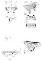
- verschiedene Ansichten eines tibialen Schneidblocks;
Figur 3- zwei Ansichten eines femoralen Schneidblocks;
- Figuren 4A und 4B
- das Schneiden eines Knochens mit einem gemäß der ersten Ausführungsformpositionierten ersten Schneidblock;
- Figuren 5A und 5B
- eine navigierbare Spalt- und Lochlehre gemäß der zweiten Ausführungsform;
Figur 6- das Schneiden weiterer Schnittebenen S1 bis S4 mit einem gemäß derzweiten Ausführungsform positionierten zweiten Schneidblock;
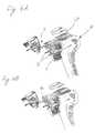
- Figuren 7A und 7B
- zwei Ausführungsformen einer zum Anbringen eines Referenzsternesan einem Knochen geeigneten erfindungsgemäßen Klemmvorrichtung;
Figur 8- die Positionierung eines Schneidblockes nach dem Stand der Technik.
- Figure 1
- a device for positioning a cutting block according to the first embodiment;
- Figures 2A to 2D
- different views of a tibial cutting block;
- Figure 3
- two views of a femoral cutting block;
- Figures 4A and 4B
- cutting a bone with a first cutting block positioned according to the first embodiment;
- Figures 5A and 5B
- a navigable gap and hole gauge according to the second embodiment;
- Figure 6
- the cutting of further cutting planes S1 to S4 with a second cutting block positioned according to the second embodiment;
- Figures 7A and 7B
- two embodiments of a clamping device according to the invention suitable for attaching a reference star to a bone;
- Figure 8
- the positioning of a cutting block according to the prior art.
Figur 1 zeigt eine erste Ausführungsform der Vorrichtung 20 mit einemReferenzstern 21 und darauf angeordneten kugelförmigen Elementen 22a bis 22c mit reflektierenderOberfläche. Zwei Infrarotkameras (nicht gezeigt) erfassen ein an den kugelförmigenElementen 22a bis 22c, welche auch als Marker bezeichnet werden, reflektiertes Licht undkann hieraus die Lage des Referenzsternes 21 im Raum ermitteln. Der Referenzstern 21 istfest mit einem Grundkörper 22 verbunden, an welchem ein drehbares Element 23 angebrachtist. Die Achsrichtung des Drehelementes kann in der gezeigten Ausführungsform in seinerfestgelegten Orientierung zum Referenzstem 21 nicht verändert werden. Am äußeren Ende des drehbaren Elementes 23 sind zwei Platten 24a, 24b unterschiedlicher Dicke angeordnet,welche so ausgerichtet sind, dass die Platten, 24a, 24b in einer Ebene liegen und die Normaleauf die jeweiligen Plattenebenen parallel zur Drehebene des drehbaren Elementes 23 ist. Einedieser Platten 24a, 24b kann in einen Führungsschlitz 1a des in den Figuren 2A bis 2E gezeigtentibialen Scheidblockes oder einen der Führungsschlitze II, III des in Figur 3 gezeigtenfemoralen Schneidblockes eingesteckt werden. Dabei ist zum Erzeugen des in Figur 4 gezeigtenSchnittes in einer ersten Schnittebene S0 lediglich das Navigieren des Schneidblockes1 bezüglich der gewünschten Schnittebene, d. h. das auf den Führungsschlitz 1a bezogeneNavigieren erforderlich. Hierbei kann der Führungsschlitz 1a in der gewünschten Schnittebeneverschoben werden, da die durch den Schneidblock 1 geführte Schneidvorrichtung 4 nur inder gewünschten Schnittebene S0 geführt werden muss.Figure 1 shows a first embodiment of the
Figur 3 zeigt einen femoralen Schneidblock, wobei eine Führung eines Schneidgerätes entwederdurch die in Figur 3 oben gezeigte Auflagefläche I oder durch eine der beiden FührungsschlitzeII oder III erfolgen kann.FIG. 3 shows a femoral cutting block, with a cutting device being guided eitherthrough the contact surface I shown in FIG. 3 above or through one of the two guide slotsII or III can be done.
Wird zum Beispiel der in Figur 2 gezeigte tibiale Schneidblock 1 mit dem in den Führungsschlitz1a eingesteckten in Figur 1 gezeigten Positionierungselement 20 an einen Knochen Knavigiert, so kann dieser Schneidblock 1 mit geeigneten Befestigungs- oder Halteelementen 3am Knochen K befestigt werden, wie in Figur 4A gezeigt. Mit einem Schneidwerkzeug 4kann ein gewünschter Schnitt in der Schnittebene S0 entweder durch Auflegen einer Klingeauf die obere Seite des Schneidblockes 1, oder durch Führen einer Klinge in einem Führungsschlitz1a, wie in Figur 4B gezeigt, erfolgen.For example, the tibial cutting block 1 shown in Figure 2 with the in the guide slot1a inserted
Die in den Figuren 5A und 5B gezeigte zweite Ausführungsform zur Bestimmungder Position eines Schneidblockes weist ebenso wie die in Figur 1 gezeigte erste Ausführungsformeinen Referenzstem 31 auf, wobei in den Figuren 5A und 5B nur die Halteelemente33a bis 33c zum Aufstecken von kugelförmigen Elementen mit reflektierenden Oberflächengezeigt sind. Mit dem Referenzstem 31 ist eine Bohrlehre 34 mit zwei darin vorgesehenenBohrlöchern 35a, 35b fest verbunden. An der in Figur 5B gezeigten Unterseite der Lehre34 können Spikes 37 zum vorläufigen Fixieren der Lehre 34 vorgesehen sein. Die in Figur5 gezeigte Bohrlehre kann durch den Referenzstern 31 so auf der in Figur 4 gezeigten Schnittebene S0 positioniert werden, dass durch die Löcher 35a und 35b geeignete Werkzeugezur Erzeugung einer Verbindungsstruktur zwischen Knochen und Schneidblock, zum BeispielHalteelemente 36 in den Knochen K eingeschoben werden, so dass der zweite Schneidblock10, wie schematisch in Figur 6 gezeigt, durch das Aufstecken auf das bzw. die Halteelemente36 richtig positioniert werden kann. Ebenso kann zum Beispiel auch ein Halteelement36 fest mit dem Schneidblock 10 verbunden sein, so dass der Schneidblock 10 mit Halteelement36 in die mit Hilfe der Bohrlehre 34 in den Knochen K gebohrten Löcher eingestecktwerden kann. Ist der zweite Schneidblock 10 in die gewünschte Position gebracht worden,so können durch die verschiedenen in dem zweiten Schneidblock 10 vorgesehenen Führungsschlitzedie gewünschten Schnitte in den Ebenen S1 bis S4 ausgeführt werden.The second embodiment shown in Figures 5A and 5B for determinationhas the position of a cutting block as well as the first embodiment shown in FIGa
Auf einen Knochen, bei welchem mit Hilfe des ersten Schneidblockes 1 und des zweitenSchneidblockes 10 die gewünschten Schnittebenen S0 bis S4 erzeugt wurden, kann ein künstlichesGelenk aufgesetzt werden, welches bei richtiger Lage der Schnittebenen S0 bis S4 auchrichtig positioniert ist.On a bone, in which the first cutting block 1 and the
Figur 7A zeigt eine erste Vorrichtung 40, mit welcher ein Referenzstern 41mit darauf angebrachten Halterungen 42a bis 42c zum Aufstecken von nicht gezeigten reflektierendenMarkern in einem definierten Lageverhältnis an einem Knochen oder einer anderenStruktur befestigt werden kann. Der zum Beispiel an einem Knochen befestigte Referenzstern41 dient als Bezugssystem zur Navigation und Positionierung der in Figur 1 und Figur 5 gezeigtenVorrichtungen. Jedoch kann die in Figur 7 gezeigte Vorrichtung auch unabhängig vonden oben beschriebenen Elementen und Vorrichtungen verwendet werden.FIG. 7A shows a
Die an der Unterseite der Vorrichtung 40 gezeigten Spikes 43, welche mit der Hülse 45 verbundensind, können durch ein Drehen der Schraube 44 ein- und ausgefahren werden. Wirdzum Beispiel eine Stange, wie zum Beispiel eine Schantzschraube oder ein Kirschnerdraht, ineinen Knochen zum Anbringen der Vorrichtung 40 eingebracht, so kann die Vorrichtung 40mit der Hülse 45 auf diese im Knochen angebrachte Stange aufgesteckt werden. Die Schraube46 dient zur Fixierung der Vorrichtung 40 an dieser Stange. Nach erfolgter Fixierung mittelsder Schraube 46 kann die Mutter 44 gedreht werden, um die Spikes 43 nach unten zu bewegenund so ein Verspannen der Vorrichtung 40 bezüglich des Knochens oder eines anderen Elementes, wie zum Beispiel Haut oder auf Haut aufgebrachte Elemente zu bewirken. Eskann somit eine ortsfeste nicht verschiebbare Verbindung eines Referenzsterns 41 an nur einereinzelnen Stange in einem Knochen erhalten werden, da eine Verspannung über die ein-bzw. ausfahrbaren Spikes 43 möglich ist. Die Position des Referenzsterns 41 kann mittels derSchrauben 47 und 48 durch Drehung um zwei Achsen verändert werden.The
Figur 7B zeigt eine zweite Ausführungsform einer Vorrichtung 40 zum ortsfesten Anbringeneines Referenzsternes 41, wobei die Spikes 43 auf einer Abstützfläche 49 angeordnet sind undmit der Fläche 49 nach unten bewegt werden, um die Vorrichtung 40 so an der Hautoberflächefest zu verspannen.FIG. 7B shows a second embodiment of a
Obwohl die Erfindung insbesondere im Hinblick auf Knie-Implantate beschrieben wurdekann diese natürlich auch bei anderen Implantaten oder Verfahren verwendet werden. Dabeikönnen insbesondere die Vorrichtung zur Navigation des Schneidblocks, die Vorrichtung zurNavigation der Lochlehre und die in Figur 7 gezeigte Klemmvorrichtung unabhängig voneinanderverwendet werden.Although the invention has been described in particular with regard to knee implantsthis can of course also be used with other implants or procedures. therecan in particular the device for navigation of the cutting block, the device forNavigation of the hole gauge and the clamping device shown in Figure 7 independently of each otherbe used.
Claims (8)
- A system for positioning an incision block (1), comprising:a reference star (21), with at least one reference point (22a, 22b, 22c), whosespatial position can be detected;an incision block (1), with a guide slit (1a); andat least one plate (24a, 24b) which may be inserted into the guide slit (1a) of theincision block (1) and which is firmly connected to said reference star (21).
- The system as set forth in claim 1, wherein at least two plates (24a, 24b) are provided,which are preferably of different thicknesses.
- The system as set forth in claim 1 or 2, wherein at least one plate (24a, 24b) can berotated and/or shifted about an axis, parallel to its vertical.
- A system for positioning an incision block (10), comprising:a reference star (31), with at least one reference point (33a, 33b, 33c), whosespatial position can be detected;an incision block (10), with holes; anda hole template (34) which is firmly connected to said reference star (31) andcomprises holes (35a, 35b) which are arranged in correspondence with holes of theincision block (10).
- A system for positioning an incision block (10), comprising:a reference star (31), with at least one reference point (33a, 33b, 33c), whosespatial position can be detected;holding elements (36);an incision block (10), which can be slipped onto said holding elements (36); anda hole template (34) which is firmly connected to the reference star (31) andcomprises holes (35a, 35b) for inserting the holding elements (36).
- The system as set forth in claim 5, wherein said hole template (34) comprises at leasttwo holes (35a, 35b).
- The system as set forth in any one of the preceding claims, wherein the reference star(21, 31) comprises at least three elements (22a, 22b, 22c; 33a, 33b, 33c) withreflecting surfaces.
- The system as set forth in any one of the preceding claims, comprising a device (40)for attaching a positioning element (41) to a bone, in a stable manner.
Priority Applications (4)
| Application Number | Priority Date | Filing Date | Title |
|---|---|---|---|
| EP01102714AEP1190676B1 (en) | 2000-09-26 | 2001-02-06 | Device for determining the position of a cutting guide |
| DE20103416UDE20103416U1 (en) | 2001-02-06 | 2001-02-27 | Device for attaching an element to a body |
| US09/860,026US6551325B2 (en) | 2000-09-26 | 2001-05-17 | Device, system and method for determining the position of an incision block |
| US09/940,699US6719757B2 (en) | 2001-02-06 | 2001-08-27 | Device for attaching an element to a body |
Applications Claiming Priority (3)
| Application Number | Priority Date | Filing Date | Title |
|---|---|---|---|
| EP00120229 | 2000-09-26 | ||
| EP00120229AEP1190675B1 (en) | 2000-09-26 | 2000-09-26 | System for navigation-assisted orientation of elements on a body |
| EP01102714AEP1190676B1 (en) | 2000-09-26 | 2001-02-06 | Device for determining the position of a cutting guide |
Publications (2)
| Publication Number | Publication Date |
|---|---|
| EP1190676A1 EP1190676A1 (en) | 2002-03-27 |
| EP1190676B1true EP1190676B1 (en) | 2003-08-13 |
Family
ID=26071401
Family Applications (1)
| Application Number | Title | Priority Date | Filing Date |
|---|---|---|---|
| EP01102714AExpired - LifetimeEP1190676B1 (en) | 2000-09-26 | 2001-02-06 | Device for determining the position of a cutting guide |
Country Status (2)
| Country | Link |
|---|---|
| US (1) | US6551325B2 (en) |
| EP (1) | EP1190676B1 (en) |
Cited By (7)
| Publication number | Priority date | Publication date | Assignee | Title |
|---|---|---|---|---|
| US7237556B2 (en) | 2002-02-11 | 2007-07-03 | Smith & Nephew, Inc. | Image-guided fracture reduction |
| US7477926B2 (en) | 2004-03-31 | 2009-01-13 | Smith & Nephew, Inc. | Methods and apparatuses for providing a reference array input device |
| US7547307B2 (en) | 2001-02-27 | 2009-06-16 | Smith & Nephew, Inc. | Computer assisted knee arthroplasty instrumentation, systems, and processes |
| US7764985B2 (en) | 2003-10-20 | 2010-07-27 | Smith & Nephew, Inc. | Surgical navigation system component fault interfaces and related processes |
| US7794467B2 (en) | 2003-11-14 | 2010-09-14 | Smith & Nephew, Inc. | Adjustable surgical cutting systems |
| US7862570B2 (en) | 2003-10-03 | 2011-01-04 | Smith & Nephew, Inc. | Surgical positioners |
| US8109942B2 (en) | 2004-04-21 | 2012-02-07 | Smith & Nephew, Inc. | Computer-aided methods, systems, and apparatuses for shoulder arthroplasty |
Families Citing this family (269)
| Publication number | Priority date | Publication date | Assignee | Title |
|---|---|---|---|---|
| AU675077B2 (en) | 1992-08-14 | 1997-01-23 | British Telecommunications Public Limited Company | Position location system |
| DE69531994T2 (en) | 1994-09-15 | 2004-07-22 | OEC Medical Systems, Inc., Boston | SYSTEM FOR POSITION DETECTION BY MEANS OF A REFERENCE UNIT ATTACHED TO A PATIENT'S HEAD FOR USE IN THE MEDICAL AREA |
| US6226548B1 (en) | 1997-09-24 | 2001-05-01 | Surgical Navigation Technologies, Inc. | Percutaneous registration apparatus and method for use in computer-assisted surgical navigation |
| US20020019387A1 (en)* | 1997-09-24 | 2002-02-14 | Smithkline Beecham Corporation | Vitronectin receptor antagonist |
| US6021343A (en) | 1997-11-20 | 2000-02-01 | Surgical Navigation Technologies | Image guided awl/tap/screwdriver |
| US6348058B1 (en) | 1997-12-12 | 2002-02-19 | Surgical Navigation Technologies, Inc. | Image guided spinal surgery guide, system, and method for use thereof |
| US6477400B1 (en) | 1998-08-20 | 2002-11-05 | Sofamor Danek Holdings, Inc. | Fluoroscopic image guided orthopaedic surgery system with intraoperative registration |
| US6470207B1 (en) | 1999-03-23 | 2002-10-22 | Surgical Navigation Technologies, Inc. | Navigational guidance via computer-assisted fluoroscopic imaging |
| US6491699B1 (en) | 1999-04-20 | 2002-12-10 | Surgical Navigation Technologies, Inc. | Instrument guidance method and system for image guided surgery |
| US7366562B2 (en) | 2003-10-17 | 2008-04-29 | Medtronic Navigation, Inc. | Method and apparatus for surgical navigation |
| US6499488B1 (en) | 1999-10-28 | 2002-12-31 | Winchester Development Associates | Surgical sensor |
| US8239001B2 (en) | 2003-10-17 | 2012-08-07 | Medtronic Navigation, Inc. | Method and apparatus for surgical navigation |
| US6474341B1 (en) | 1999-10-28 | 2002-11-05 | Surgical Navigation Technologies, Inc. | Surgical communication and power system |
| US6381485B1 (en) | 1999-10-28 | 2002-04-30 | Surgical Navigation Technologies, Inc. | Registration of human anatomy integrated for electromagnetic localization |
| US8644907B2 (en) | 1999-10-28 | 2014-02-04 | Medtronic Navigaton, Inc. | Method and apparatus for surgical navigation |
| US11331150B2 (en) | 1999-10-28 | 2022-05-17 | Medtronic Navigation, Inc. | Method and apparatus for surgical navigation |
| US6379302B1 (en) | 1999-10-28 | 2002-04-30 | Surgical Navigation Technologies Inc. | Navigation information overlay onto ultrasound imagery |
| US6493573B1 (en) | 1999-10-28 | 2002-12-10 | Winchester Development Associates | Method and system for navigating a catheter probe in the presence of field-influencing objects |
| US7104996B2 (en)* | 2000-01-14 | 2006-09-12 | Marctec. Llc | Method of performing surgery |
| US7635390B1 (en) | 2000-01-14 | 2009-12-22 | Marctec, Llc | Joint replacement component having a modular articulating surface |
| US6725080B2 (en) | 2000-03-01 | 2004-04-20 | Surgical Navigation Technologies, Inc. | Multiple cannula image guided tool for image guided procedures |
| US6535756B1 (en) | 2000-04-07 | 2003-03-18 | Surgical Navigation Technologies, Inc. | Trajectory storage apparatus and method for surgical navigation system |
| US7085400B1 (en) | 2000-06-14 | 2006-08-01 | Surgical Navigation Technologies, Inc. | System and method for image based sensor calibration |
| GB0101990D0 (en)* | 2001-01-25 | 2001-03-14 | Finsbury Dev Ltd | Surgical system |
| US20050113846A1 (en)* | 2001-02-27 | 2005-05-26 | Carson Christopher P. | Surgical navigation systems and processes for unicompartmental knee arthroplasty |
| US6636757B1 (en)* | 2001-06-04 | 2003-10-21 | Surgical Navigation Technologies, Inc. | Method and apparatus for electromagnetic navigation of a surgical probe near a metal object |
| US7708741B1 (en) | 2001-08-28 | 2010-05-04 | Marctec, Llc | Method of preparing bones for knee replacement surgery |
| US7618421B2 (en)* | 2001-10-10 | 2009-11-17 | Howmedica Osteonics Corp. | Tools for femoral resection in knee surgery |
| AU2002361572A1 (en)* | 2001-10-19 | 2003-04-28 | University Of North Carolina At Chape Hill | Methods and systems for dynamic virtual convergence and head mountable display |
| US6947786B2 (en) | 2002-02-28 | 2005-09-20 | Surgical Navigation Technologies, Inc. | Method and apparatus for perspective inversion |
| TW200304608A (en)* | 2002-03-06 | 2003-10-01 | Z Kat Inc | System and method for using a haptic device in combination with a computer-assisted surgery system |
| US8996169B2 (en) | 2011-12-29 | 2015-03-31 | Mako Surgical Corp. | Neural monitor-based dynamic haptics |
| US11202676B2 (en) | 2002-03-06 | 2021-12-21 | Mako Surgical Corp. | Neural monitor-based dynamic haptics |
| US8010180B2 (en) | 2002-03-06 | 2011-08-30 | Mako Surgical Corp. | Haptic guidance system and method |
| US6990368B2 (en) | 2002-04-04 | 2006-01-24 | Surgical Navigation Technologies, Inc. | Method and apparatus for virtual digital subtraction angiography |
| US7998062B2 (en) | 2004-03-29 | 2011-08-16 | Superdimension, Ltd. | Endoscope structures and techniques for navigating to a target in branched structure |
| US7048741B2 (en)* | 2002-05-10 | 2006-05-23 | Swanson Todd V | Method and apparatus for minimally invasive knee arthroplasty |
| US7153303B2 (en)* | 2002-06-19 | 2006-12-26 | Sdgi Holdings, Inc. | Guide and blade for contouring vertebral bodies |
| AU2003257309A1 (en) | 2002-08-13 | 2004-02-25 | Microbotics Corporation | Microsurgical robot system |
| US6892090B2 (en) | 2002-08-19 | 2005-05-10 | Surgical Navigation Technologies, Inc. | Method and apparatus for virtual endoscopy |
| US7736368B2 (en)* | 2002-08-23 | 2010-06-15 | Orthosoft Inc. | Surgical universal positioning block and tool guide |
| AU2003258434B8 (en)* | 2002-08-23 | 2009-03-05 | Orthosoft Ulc | Total knee replacement surgery system |
| US20040039396A1 (en)* | 2002-08-23 | 2004-02-26 | Orthosoft Inc. | Universal positioning block |
| US20040068263A1 (en)* | 2002-10-04 | 2004-04-08 | Benoit Chouinard | CAS bone reference with articulated support |
| JP2006509609A (en) | 2002-10-04 | 2006-03-23 | オルトソフト インコーポレイテッド | Computer-aided hip replacement surgery |
| US7697972B2 (en) | 2002-11-19 | 2010-04-13 | Medtronic Navigation, Inc. | Navigation system for cardiac therapies |
| US7599730B2 (en) | 2002-11-19 | 2009-10-06 | Medtronic Navigation, Inc. | Navigation system for cardiac therapies |
| US7094241B2 (en) | 2002-11-27 | 2006-08-22 | Zimmer Technology, Inc. | Method and apparatus for achieving correct limb alignment in unicondylar knee arthroplasty |
| US7029477B2 (en)* | 2002-12-20 | 2006-04-18 | Zimmer Technology, Inc. | Surgical instrument and positioning method |
| US20040172044A1 (en)* | 2002-12-20 | 2004-09-02 | Grimm James E. | Surgical instrument and method of positioning same |
| US20070282347A9 (en)* | 2002-12-20 | 2007-12-06 | Grimm James E | Navigated orthopaedic guide and method |
| US20040122305A1 (en)* | 2002-12-20 | 2004-06-24 | Grimm James E. | Surgical instrument and method of positioning same |
| US7542791B2 (en) | 2003-01-30 | 2009-06-02 | Medtronic Navigation, Inc. | Method and apparatus for preplanning a surgical procedure |
| US7660623B2 (en) | 2003-01-30 | 2010-02-09 | Medtronic Navigation, Inc. | Six degree of freedom alignment display for medical procedures |
| US20040153066A1 (en)* | 2003-02-03 | 2004-08-05 | Coon Thomas M. | Apparatus for knee surgery and method of use |
| EP1615577A2 (en)* | 2003-02-04 | 2006-01-18 | Orthosoft, Inc. | Cas modular bone reference assembly and limb position measurement system |
| US20040152955A1 (en)* | 2003-02-04 | 2004-08-05 | Mcginley Shawn E. | Guidance system for rotary surgical instrument |
| US7458977B2 (en)* | 2003-02-04 | 2008-12-02 | Zimmer Technology, Inc. | Surgical navigation instrument useful in marking anatomical structures |
| US20050267354A1 (en)* | 2003-02-04 | 2005-12-01 | Joel Marquart | System and method for providing computer assistance with spinal fixation procedures |
| EP1605810A2 (en)* | 2003-02-04 | 2005-12-21 | Z-Kat, Inc. | Computer-assisted knee replacement apparatus and method |
| US20040171930A1 (en)* | 2003-02-04 | 2004-09-02 | Zimmer Technology, Inc. | Guidance system for rotary surgical instrument |
| WO2004069040A2 (en)* | 2003-02-04 | 2004-08-19 | Z-Kat, Inc. | Method and apparatus for computer assistance with intramedullary nail procedure |
| US7160307B2 (en)* | 2003-02-10 | 2007-01-09 | Smith & Nephew, Inc. | Hip replacement incision locator |
| DE10309500A1 (en)* | 2003-02-26 | 2004-09-16 | Aesculap Ag & Co. Kg | Patella reference device |
| FR2852223B1 (en) | 2003-03-11 | 2005-06-10 | Perception Raisonnement Action En Medecine | INSTRUMENT FOR TRACKING THE POSITION OF A CUTTING PLAN |
| US7570791B2 (en) | 2003-04-25 | 2009-08-04 | Medtronic Navigation, Inc. | Method and apparatus for performing 2D to 3D registration |
| US7559931B2 (en)* | 2003-06-09 | 2009-07-14 | OrthAlign, Inc. | Surgical orientation system and method |
| WO2004112610A2 (en)* | 2003-06-09 | 2004-12-29 | Vitruvian Orthopaedics, Llc | Surgical orientation device and method |
| US7313430B2 (en) | 2003-08-28 | 2007-12-25 | Medtronic Navigation, Inc. | Method and apparatus for performing stereotactic surgery |
| AU2003273871A1 (en)* | 2003-09-13 | 2005-04-21 | Aesculap Ag And Co. Kg | Method and device for determining the angle between the femur and the tibia |
| EP2113189B1 (en) | 2003-09-15 | 2013-09-04 | Covidien LP | System of accessories for use with bronchoscopes |
| EP2316328B1 (en) | 2003-09-15 | 2012-05-09 | Super Dimension Ltd. | Wrap-around holding device for use with bronchoscopes |
| US7835778B2 (en) | 2003-10-16 | 2010-11-16 | Medtronic Navigation, Inc. | Method and apparatus for surgical navigation of a multiple piece construct for implantation |
| US7840253B2 (en) | 2003-10-17 | 2010-11-23 | Medtronic Navigation, Inc. | Method and apparatus for surgical navigation |
| US7641661B2 (en) | 2003-12-26 | 2010-01-05 | Zimmer Technology, Inc. | Adjustable resection guide |
| WO2005063139A1 (en)* | 2003-12-30 | 2005-07-14 | Depuy International Ltd | An instrument system for use in a surgical procedure |
| EP1561431B1 (en)* | 2004-02-03 | 2009-08-12 | BrainLAB AG | Device for determining the position of a cutting guide |
| US20050267353A1 (en)* | 2004-02-04 | 2005-12-01 | Joel Marquart | Computer-assisted knee replacement apparatus and method |
| US8764725B2 (en) | 2004-02-09 | 2014-07-01 | Covidien Lp | Directional anchoring mechanism, method and applications thereof |
| US7901411B2 (en)* | 2004-02-10 | 2011-03-08 | Smith & Nephew, Inc. | Hip replacement incision locator |
| US20050215888A1 (en)* | 2004-03-05 | 2005-09-29 | Grimm James E | Universal support arm and tracking array |
| US20060052691A1 (en)* | 2004-03-05 | 2006-03-09 | Hall Maleata Y | Adjustable navigated tracking element mount |
| US7641660B2 (en)* | 2004-03-08 | 2010-01-05 | Biomet Manufacturing Corporation | Method, apparatus, and system for image guided bone cutting |
| US7993341B2 (en) | 2004-03-08 | 2011-08-09 | Zimmer Technology, Inc. | Navigated orthopaedic guide and method |
| US8114086B2 (en)* | 2004-03-08 | 2012-02-14 | Zimmer Technology, Inc. | Navigated cut guide locator |
| GB0405386D0 (en)* | 2004-03-10 | 2004-04-21 | Depuy Int Ltd | Device |
| US20050245820A1 (en)* | 2004-04-28 | 2005-11-03 | Sarin Vineet K | Method and apparatus for verifying and correcting tracking of an anatomical structure during surgery |
| US7567834B2 (en) | 2004-05-03 | 2009-07-28 | Medtronic Navigation, Inc. | Method and apparatus for implantation between two vertebral bodies |
| FR2871363B1 (en)* | 2004-06-15 | 2006-09-01 | Medtech Sa | ROBOTIZED GUIDING DEVICE FOR SURGICAL TOOL |
| US8167888B2 (en)* | 2004-08-06 | 2012-05-01 | Zimmer Technology, Inc. | Tibial spacer blocks and femoral cutting guide |
| US7874686B2 (en)* | 2004-09-27 | 2011-01-25 | Brainlab Ag | Reflective marker and method for its manufacture |
| DE502004004450D1 (en)* | 2004-09-27 | 2007-09-06 | Brainlab Ag | Reflective marker and method for its preparation |
| US20060084863A1 (en)* | 2004-10-15 | 2006-04-20 | Jacek Kluzik | Positional verification |
| DE102004063977A1 (en)* | 2004-10-19 | 2006-06-22 | Mathys Ag Bettlach | Ligament Tension Device, Cutting Guide and Osteotomy Technique |
| US7636595B2 (en) | 2004-10-28 | 2009-12-22 | Medtronic Navigation, Inc. | Method and apparatus for calibrating non-linear instruments |
| US8535329B2 (en)* | 2004-10-29 | 2013-09-17 | Kinamed, Inc. | Tracking tools and method for computer-assisted shoulder replacement surgery |
| US20060155293A1 (en)* | 2005-01-07 | 2006-07-13 | Zimmer Technology | External rotation cut guide |
| US20060161059A1 (en)* | 2005-01-20 | 2006-07-20 | Zimmer Technology, Inc. | Variable geometry reference array |
| US20060195111A1 (en)* | 2005-01-25 | 2006-08-31 | Orthosoft Inc. | Universal positioning block assembly |
| US20060200158A1 (en)* | 2005-01-29 | 2006-09-07 | Farling Toby N | Apparatuses and methods for arthroplastic surgery |
| EP1690503B1 (en)* | 2005-02-15 | 2013-07-24 | BrainLAB AG | User guidance for adjusting the cutting guides for the bones |
| WO2006091704A1 (en) | 2005-02-22 | 2006-08-31 | Smith & Nephew, Inc. | In-line milling system |
| US20060241654A1 (en)* | 2005-02-22 | 2006-10-26 | Jury Baldewein | Surgical instrument combination |
| US20060235290A1 (en)* | 2005-04-04 | 2006-10-19 | Aesculap Ag & Co. Kg | Method and apparatus for positioning a cutting tool for orthopedic surgery using a localization system |
| US20060241638A1 (en)* | 2005-04-08 | 2006-10-26 | Zimmer Technology, Inc. | Anatomical landmark guide |
| US20070162142A1 (en)* | 2005-06-15 | 2007-07-12 | Vitruvian Orthopaedics, Llc | Knee surgery method and apparatus |
| US7840256B2 (en) | 2005-06-27 | 2010-11-23 | Biomet Manufacturing Corporation | Image guided tracking array and method |
| US20070073136A1 (en)* | 2005-09-15 | 2007-03-29 | Robert Metzger | Bone milling with image guided surgery |
| US20070066917A1 (en)* | 2005-09-20 | 2007-03-22 | Hodorek Robert A | Method for simulating prosthetic implant selection and placement |
| US7835784B2 (en) | 2005-09-21 | 2010-11-16 | Medtronic Navigation, Inc. | Method and apparatus for positioning a reference frame |
| EP1769769A1 (en)* | 2005-09-28 | 2007-04-04 | DePuy Orthopädie GmbH | Tracking surgical items |
| US20070100346A1 (en)* | 2005-10-27 | 2007-05-03 | Wyss Joseph G | Support for locating instrument guides |
| EP1779799B1 (en)* | 2005-10-27 | 2008-12-17 | BrainLAB AG | Device for fixing a reference element |
| US20070100338A1 (en)* | 2005-10-27 | 2007-05-03 | Deffenbaugh Daren L | Orthopaedic instrument joint, instrument and associated method |
| US20070123856A1 (en)* | 2005-10-27 | 2007-05-31 | Deffenbaugh Daren L | Trauma joint, external fixator and associated method |
| US20070123857A1 (en)* | 2005-10-27 | 2007-05-31 | Deffenbaugh Daren L | Orthopaedic joint, device and associated method |
| US20070149977A1 (en)* | 2005-11-28 | 2007-06-28 | Zimmer Technology, Inc. | Surgical component positioner |
| US20070156066A1 (en)* | 2006-01-03 | 2007-07-05 | Zimmer Technology, Inc. | Device for determining the shape of an anatomic surface |
| US7520880B2 (en) | 2006-01-09 | 2009-04-21 | Zimmer Technology, Inc. | Adjustable surgical support base with integral hinge |
| US7744600B2 (en)* | 2006-01-10 | 2010-06-29 | Zimmer Technology, Inc. | Bone resection guide and method |
| US9168102B2 (en) | 2006-01-18 | 2015-10-27 | Medtronic Navigation, Inc. | Method and apparatus for providing a container to a sterile environment |
| US7780671B2 (en)* | 2006-01-23 | 2010-08-24 | Zimmer Technology, Inc. | Bone resection apparatus and method for knee surgery |
| US20070233138A1 (en)* | 2006-01-27 | 2007-10-04 | Zimmer Technology, Inc. | Apparatuses and methods for arthroplastic surgery |
| US20070186738A1 (en)* | 2006-01-31 | 2007-08-16 | Zimmer Technology, Inc. | Tibial cut guide assembly having rotatable cut guide body |
| US20070233156A1 (en)* | 2006-02-16 | 2007-10-04 | Robert Metzger | Surgical instrument |
| US20070239153A1 (en)* | 2006-02-22 | 2007-10-11 | Hodorek Robert A | Computer assisted surgery system using alternative energy technology |
| US9289253B2 (en) | 2006-02-27 | 2016-03-22 | Biomet Manufacturing, Llc | Patient-specific shoulder guide |
| US9907659B2 (en) | 2007-04-17 | 2018-03-06 | Biomet Manufacturing, Llc | Method and apparatus for manufacturing an implant |
| US8591516B2 (en) | 2006-02-27 | 2013-11-26 | Biomet Manufacturing, Llc | Patient-specific orthopedic instruments |
| US9345548B2 (en) | 2006-02-27 | 2016-05-24 | Biomet Manufacturing, Llc | Patient-specific pre-operative planning |
| US8608748B2 (en) | 2006-02-27 | 2013-12-17 | Biomet Manufacturing, Llc | Patient specific guides |
| US10278711B2 (en) | 2006-02-27 | 2019-05-07 | Biomet Manufacturing, Llc | Patient-specific femoral guide |
| US9113971B2 (en) | 2006-02-27 | 2015-08-25 | Biomet Manufacturing, Llc | Femoral acetabular impingement guide |
| US8535387B2 (en) | 2006-02-27 | 2013-09-17 | Biomet Manufacturing, Llc | Patient-specific tools and implants |
| US20150335438A1 (en) | 2006-02-27 | 2015-11-26 | Biomet Manufacturing, Llc. | Patient-specific augments |
| US9339278B2 (en) | 2006-02-27 | 2016-05-17 | Biomet Manufacturing, Llc | Patient-specific acetabular guides and associated instruments |
| US9918740B2 (en) | 2006-02-27 | 2018-03-20 | Biomet Manufacturing, Llc | Backup surgical instrument system and method |
| US8603180B2 (en) | 2006-02-27 | 2013-12-10 | Biomet Manufacturing, Llc | Patient-specific acetabular alignment guides |
| US9173661B2 (en) | 2006-02-27 | 2015-11-03 | Biomet Manufacturing, Llc | Patient specific alignment guide with cutting surface and laser indicator |
| US7967868B2 (en) | 2007-04-17 | 2011-06-28 | Biomet Manufacturing Corp. | Patient-modified implant and associated method |
| US8568487B2 (en) | 2006-02-27 | 2013-10-29 | Biomet Manufacturing, Llc | Patient-specific hip joint devices |
| US8407067B2 (en) | 2007-04-17 | 2013-03-26 | Biomet Manufacturing Corp. | Method and apparatus for manufacturing an implant |
| US8377066B2 (en) | 2006-02-27 | 2013-02-19 | Biomet Manufacturing Corp. | Patient-specific elbow guides and associated methods |
| US8608749B2 (en) | 2006-02-27 | 2013-12-17 | Biomet Manufacturing, Llc | Patient-specific acetabular guides and associated instruments |
| CA2644574C (en)* | 2006-03-17 | 2016-11-08 | Zimmer, Inc. | Methods of predetermining the contour of a resected bone surface and assessing the fit of a prosthesis on the bone |
| US8337508B2 (en)* | 2006-03-20 | 2012-12-25 | Perception Raisonnement Action En Medecine | Distractor system |
| US8112292B2 (en) | 2006-04-21 | 2012-02-07 | Medtronic Navigation, Inc. | Method and apparatus for optimizing a therapy |
| WO2007136769A2 (en) | 2006-05-19 | 2007-11-29 | Mako Surgical Corp. | Method and apparatus for controlling a haptic device |
| US9795399B2 (en) | 2006-06-09 | 2017-10-24 | Biomet Manufacturing, Llc | Patient-specific knee alignment guide and associated method |
| US20110057930A1 (en)* | 2006-07-26 | 2011-03-10 | Inneroptic Technology Inc. | System and method of using high-speed, high-resolution depth extraction to provide three-dimensional imagery for endoscopy |
| US7728868B2 (en) | 2006-08-02 | 2010-06-01 | Inneroptic Technology, Inc. | System and method of providing real-time dynamic imagery of a medical procedure site using multiple modalities |
| US8660635B2 (en) | 2006-09-29 | 2014-02-25 | Medtronic, Inc. | Method and apparatus for optimizing a computer assisted surgical procedure |
| GB2442441B (en) | 2006-10-03 | 2011-11-09 | Biomet Uk Ltd | Surgical instrument |
| US7947862B2 (en)* | 2006-10-31 | 2011-05-24 | Depuy Products, Inc. | Limb stabilizing system for arthroplasty |
| US8187279B2 (en)* | 2006-10-31 | 2012-05-29 | Depuy Products, Inc. | Surgical instrument system with ball and socket support |
| US20090234360A1 (en)* | 2006-12-12 | 2009-09-17 | Vladimir Alexander | Laser assisted total joint arthroplasty |
| US20080161824A1 (en)* | 2006-12-27 | 2008-07-03 | Howmedica Osteonics Corp. | System and method for performing femoral sizing through navigation |
| EP1958575B1 (en)* | 2007-02-13 | 2014-08-13 | Brainlab AG | Device or system for positioning or preparing the positioning of a medical operating instrument, especially an incision block or a cutting block or a ligament balancing device |
| US20090018544A1 (en)* | 2007-07-13 | 2009-01-15 | Zimmer, Inc. | Method and apparatus for soft tissue balancing |
| US9179983B2 (en) | 2007-08-14 | 2015-11-10 | Zimmer, Inc. | Method of determining a contour of an anatomical structure and selecting an orthopaedic implant to replicate the anatomical structure |
| US8905920B2 (en) | 2007-09-27 | 2014-12-09 | Covidien Lp | Bronchoscope adapter and method |
| ES2784016T3 (en)* | 2007-11-19 | 2020-09-21 | Blue Ortho | Hip implant registration in computer-assisted surgery |
| US8571637B2 (en)* | 2008-01-21 | 2013-10-29 | Biomet Manufacturing, Llc | Patella tracking method and apparatus for use in surgical navigation |
| WO2009094646A2 (en)* | 2008-01-24 | 2009-07-30 | The University Of North Carolina At Chapel Hill | Methods, systems, and computer readable media for image guided ablation |
| ITFI20080029A1 (en)* | 2008-02-21 | 2009-08-22 | I & S R L | UNIVERSAL CUTTING GUIDE FOR KNEE TOTAL PROSTHESIS INTERVENTIONS. |
| US8340379B2 (en) | 2008-03-07 | 2012-12-25 | Inneroptic Technology, Inc. | Systems and methods for displaying guidance data based on updated deformable imaging data |
| WO2009122273A2 (en) | 2008-04-03 | 2009-10-08 | Superdimension, Ltd. | Magnetic interference detection system and method |
| EP2297673B1 (en) | 2008-06-03 | 2020-04-22 | Covidien LP | Feature-based registration method |
| US8218847B2 (en) | 2008-06-06 | 2012-07-10 | Superdimension, Ltd. | Hybrid registration method |
| US20090312629A1 (en)* | 2008-06-13 | 2009-12-17 | Inneroptic Technology Inc. | Correction of relative tracking errors based on a fiducial |
| US8932207B2 (en) | 2008-07-10 | 2015-01-13 | Covidien Lp | Integrated multi-functional endoscopic tool |
| AU2009273863B2 (en) | 2008-07-24 | 2014-12-18 | OrthAlign, Inc. | Systems and methods for joint replacement |
| AU2009291743B2 (en) | 2008-09-10 | 2015-02-05 | Orthalign, Inc | Hip surgery systems and methods |
| US8165658B2 (en) | 2008-09-26 | 2012-04-24 | Medtronic, Inc. | Method and apparatus for positioning a guide relative to a base |
| US8175681B2 (en) | 2008-12-16 | 2012-05-08 | Medtronic Navigation Inc. | Combination of electromagnetic and electropotential localization |
| US8690776B2 (en) | 2009-02-17 | 2014-04-08 | Inneroptic Technology, Inc. | Systems, methods, apparatuses, and computer-readable media for image guided surgery |
| US8641621B2 (en) | 2009-02-17 | 2014-02-04 | Inneroptic Technology, Inc. | Systems, methods, apparatuses, and computer-readable media for image management in image-guided medical procedures |
| US8554307B2 (en) | 2010-04-12 | 2013-10-08 | Inneroptic Technology, Inc. | Image annotation in image-guided medical procedures |
| US11464578B2 (en) | 2009-02-17 | 2022-10-11 | Inneroptic Technology, Inc. | Systems, methods, apparatuses, and computer-readable media for image management in image-guided medical procedures |
| US8611984B2 (en) | 2009-04-08 | 2013-12-17 | Covidien Lp | Locatable catheter |
| US9655628B2 (en) | 2009-05-06 | 2017-05-23 | Blue Ortho | Reduced invasivity fixation system for trackers in computer assisted surgery |
| ES2545398T3 (en)* | 2009-06-30 | 2015-09-10 | Blue Ortho | Adjustable guide for computer-assisted orthopedic surgery |
| US10869771B2 (en) | 2009-07-24 | 2020-12-22 | OrthAlign, Inc. | Systems and methods for joint replacement |
| US8118815B2 (en) | 2009-07-24 | 2012-02-21 | OrthAlign, Inc. | Systems and methods for joint replacement |
| WO2011014687A2 (en)* | 2009-07-31 | 2011-02-03 | Inneroptic Technology, Inc. | Dual-tube stereoscope |
| DE102009028503B4 (en) | 2009-08-13 | 2013-11-14 | Biomet Manufacturing Corp. | Resection template for the resection of bones, method for producing such a resection template and operation set for performing knee joint surgery |
| US8494613B2 (en) | 2009-08-31 | 2013-07-23 | Medtronic, Inc. | Combination localization system |
| US8494614B2 (en) | 2009-08-31 | 2013-07-23 | Regents Of The University Of Minnesota | Combination localization system |
| US20110082351A1 (en)* | 2009-10-07 | 2011-04-07 | Inneroptic Technology, Inc. | Representing measurement information during a medical procedure |
| US9282947B2 (en) | 2009-12-01 | 2016-03-15 | Inneroptic Technology, Inc. | Imager focusing based on intraoperative data |
| AU2011341678B2 (en)* | 2010-01-21 | 2014-12-11 | OrthAlign, Inc. | Systems and methods for joint replacement |
| US8632547B2 (en)* | 2010-02-26 | 2014-01-21 | Biomet Sports Medicine, Llc | Patient-specific osteotomy devices and methods |
| US9706948B2 (en) | 2010-05-06 | 2017-07-18 | Sachin Bhandari | Inertial sensor based surgical navigation system for knee replacement surgery |
| US10582834B2 (en) | 2010-06-15 | 2020-03-10 | Covidien Lp | Locatable expandable working channel and method |
| US9271744B2 (en) | 2010-09-29 | 2016-03-01 | Biomet Manufacturing, Llc | Patient-specific guide for partial acetabular socket replacement |
| US9968376B2 (en) | 2010-11-29 | 2018-05-15 | Biomet Manufacturing, Llc | Patient-specific orthopedic instruments |
| ES2599850T3 (en) | 2011-02-01 | 2017-02-03 | Nextremity Solutions, Inc. | Bone defect repair device |
| US9241745B2 (en) | 2011-03-07 | 2016-01-26 | Biomet Manufacturing, Llc | Patient-specific femoral version guide |
| US8715289B2 (en) | 2011-04-15 | 2014-05-06 | Biomet Manufacturing, Llc | Patient-specific numerically controlled instrument |
| US9675400B2 (en) | 2011-04-19 | 2017-06-13 | Biomet Manufacturing, Llc | Patient-specific fracture fixation instrumentation and method |
| US8668700B2 (en) | 2011-04-29 | 2014-03-11 | Biomet Manufacturing, Llc | Patient-specific convertible guides |
| US8956364B2 (en) | 2011-04-29 | 2015-02-17 | Biomet Manufacturing, Llc | Patient-specific partial knee guides and other instruments |
| US20150088142A1 (en)* | 2011-06-01 | 2015-03-26 | Smith & Nephew, Inc. | Patient specific instrument |
| US8532807B2 (en) | 2011-06-06 | 2013-09-10 | Biomet Manufacturing, Llc | Pre-operative planning and manufacturing method for orthopedic procedure |
| US9084618B2 (en) | 2011-06-13 | 2015-07-21 | Biomet Manufacturing, Llc | Drill guides for confirming alignment of patient-specific alignment guides |
| US8764760B2 (en) | 2011-07-01 | 2014-07-01 | Biomet Manufacturing, Llc | Patient-specific bone-cutting guidance instruments and methods |
| US20130001121A1 (en) | 2011-07-01 | 2013-01-03 | Biomet Manufacturing Corp. | Backup kit for a patient-specific arthroplasty kit assembly |
| US8597365B2 (en) | 2011-08-04 | 2013-12-03 | Biomet Manufacturing, Llc | Patient-specific pelvic implants for acetabular reconstruction |
| US9295497B2 (en) | 2011-08-31 | 2016-03-29 | Biomet Manufacturing, Llc | Patient-specific sacroiliac and pedicle guides |
| US9066734B2 (en) | 2011-08-31 | 2015-06-30 | Biomet Manufacturing, Llc | Patient-specific sacroiliac guides and associated methods |
| US9386993B2 (en) | 2011-09-29 | 2016-07-12 | Biomet Manufacturing, Llc | Patient-specific femoroacetabular impingement instruments and methods |
| US9451973B2 (en) | 2011-10-27 | 2016-09-27 | Biomet Manufacturing, Llc | Patient specific glenoid guide |
| WO2013062848A1 (en) | 2011-10-27 | 2013-05-02 | Biomet Manufacturing Corporation | Patient-specific glenoid guides |
| US9301812B2 (en) | 2011-10-27 | 2016-04-05 | Biomet Manufacturing, Llc | Methods for patient-specific shoulder arthroplasty |
| KR20130046337A (en) | 2011-10-27 | 2013-05-07 | 삼성전자주식회사 | Multi-view device and contol method thereof, display apparatus and contol method thereof, and display system |
| US9554910B2 (en) | 2011-10-27 | 2017-01-31 | Biomet Manufacturing, Llc | Patient-specific glenoid guide and implants |
| US8670816B2 (en) | 2012-01-30 | 2014-03-11 | Inneroptic Technology, Inc. | Multiple medical device guidance |
| US9237950B2 (en) | 2012-02-02 | 2016-01-19 | Biomet Manufacturing, Llc | Implant with patient-specific porous structure |
| US9549742B2 (en) | 2012-05-18 | 2017-01-24 | OrthAlign, Inc. | Devices and methods for knee arthroplasty |
| US9649160B2 (en) | 2012-08-14 | 2017-05-16 | OrthAlign, Inc. | Hip replacement navigation system and method |
| US9204977B2 (en) | 2012-12-11 | 2015-12-08 | Biomet Manufacturing, Llc | Patient-specific acetabular guide for anterior approach |
| US9060788B2 (en) | 2012-12-11 | 2015-06-23 | Biomet Manufacturing, Llc | Patient-specific acetabular guide for anterior approach |
| US9839438B2 (en) | 2013-03-11 | 2017-12-12 | Biomet Manufacturing, Llc | Patient-specific glenoid guide with a reusable guide holder |
| US9579107B2 (en) | 2013-03-12 | 2017-02-28 | Biomet Manufacturing, Llc | Multi-point fit for patient specific guide |
| US9826981B2 (en) | 2013-03-13 | 2017-11-28 | Biomet Manufacturing, Llc | Tangential fit of patient-specific guides |
| US9498233B2 (en) | 2013-03-13 | 2016-11-22 | Biomet Manufacturing, Llc. | Universal acetabular guide and associated hardware |
| US10314559B2 (en) | 2013-03-14 | 2019-06-11 | Inneroptic Technology, Inc. | Medical device guidance |
| US9517145B2 (en) | 2013-03-15 | 2016-12-13 | Biomet Manufacturing, Llc | Guide alignment system and method |
| US20150112349A1 (en) | 2013-10-21 | 2015-04-23 | Biomet Manufacturing, Llc | Ligament Guide Registration |
| US10282488B2 (en) | 2014-04-25 | 2019-05-07 | Biomet Manufacturing, Llc | HTO guide with optional guided ACL/PCL tunnels |
| US9408616B2 (en) | 2014-05-12 | 2016-08-09 | Biomet Manufacturing, Llc | Humeral cut guide |
| US9561040B2 (en) | 2014-06-03 | 2017-02-07 | Biomet Manufacturing, Llc | Patient-specific glenoid depth control |
| US9839436B2 (en) | 2014-06-03 | 2017-12-12 | Biomet Manufacturing, Llc | Patient-specific glenoid depth control |
| US10952593B2 (en) | 2014-06-10 | 2021-03-23 | Covidien Lp | Bronchoscope adapter |
| US9826994B2 (en) | 2014-09-29 | 2017-11-28 | Biomet Manufacturing, Llc | Adjustable glenoid pin insertion guide |
| US9833245B2 (en) | 2014-09-29 | 2017-12-05 | Biomet Sports Medicine, Llc | Tibial tubercule osteotomy |
| US9901406B2 (en) | 2014-10-02 | 2018-02-27 | Inneroptic Technology, Inc. | Affected region display associated with a medical device |
| US10188467B2 (en) | 2014-12-12 | 2019-01-29 | Inneroptic Technology, Inc. | Surgical guidance intersection display |
| US10363149B2 (en) | 2015-02-20 | 2019-07-30 | OrthAlign, Inc. | Hip replacement navigation system and method |
| US9820868B2 (en) | 2015-03-30 | 2017-11-21 | Biomet Manufacturing, Llc | Method and apparatus for a pin apparatus |
| US10426555B2 (en) | 2015-06-03 | 2019-10-01 | Covidien Lp | Medical instrument with sensor for use in a system and method for electromagnetic navigation |
| US10568647B2 (en) | 2015-06-25 | 2020-02-25 | Biomet Manufacturing, Llc | Patient-specific humeral guide designs |
| US10226262B2 (en) | 2015-06-25 | 2019-03-12 | Biomet Manufacturing, Llc | Patient-specific humeral guide designs |
| USD823470S1 (en) | 2015-07-10 | 2018-07-17 | Brainlab Ag | Reference array |
| US9949700B2 (en) | 2015-07-22 | 2018-04-24 | Inneroptic Technology, Inc. | Medical device approaches |
| US9962134B2 (en) | 2015-10-28 | 2018-05-08 | Medtronic Navigation, Inc. | Apparatus and method for maintaining image quality while minimizing X-ray dosage of a patient |
| US9675319B1 (en) | 2016-02-17 | 2017-06-13 | Inneroptic Technology, Inc. | Loupe display |
| US10314599B2 (en) | 2016-03-31 | 2019-06-11 | Howmedica Osteonics Corp. | Navigated patella clamp |
| US10478254B2 (en) | 2016-05-16 | 2019-11-19 | Covidien Lp | System and method to access lung tissue |
| US10588696B2 (en) | 2016-08-03 | 2020-03-17 | Mako Surgical Corp. | Patella implant planning |
| US10278778B2 (en) | 2016-10-27 | 2019-05-07 | Inneroptic Technology, Inc. | Medical device navigation using a virtual 3D space |
| US10418705B2 (en) | 2016-10-28 | 2019-09-17 | Covidien Lp | Electromagnetic navigation antenna assembly and electromagnetic navigation system including the same |
| US10751126B2 (en) | 2016-10-28 | 2020-08-25 | Covidien Lp | System and method for generating a map for electromagnetic navigation |
| US10722311B2 (en) | 2016-10-28 | 2020-07-28 | Covidien Lp | System and method for identifying a location and/or an orientation of an electromagnetic sensor based on a map |
| US10792106B2 (en) | 2016-10-28 | 2020-10-06 | Covidien Lp | System for calibrating an electromagnetic navigation system |
| US10446931B2 (en) | 2016-10-28 | 2019-10-15 | Covidien Lp | Electromagnetic navigation antenna assembly and electromagnetic navigation system including the same |
| US10615500B2 (en) | 2016-10-28 | 2020-04-07 | Covidien Lp | System and method for designing electromagnetic navigation antenna assemblies |
| US10638952B2 (en) | 2016-10-28 | 2020-05-05 | Covidien Lp | Methods, systems, and computer-readable media for calibrating an electromagnetic navigation system |
| US10517505B2 (en) | 2016-10-28 | 2019-12-31 | Covidien Lp | Systems, methods, and computer-readable media for optimizing an electromagnetic navigation system |
| US10722310B2 (en) | 2017-03-13 | 2020-07-28 | Zimmer Biomet CMF and Thoracic, LLC | Virtual surgery planning system and method |
| EP3595554A4 (en) | 2017-03-14 | 2021-01-06 | OrthAlign, Inc. | Hip replacement navigation systems and methods |
| CA3056495A1 (en) | 2017-03-14 | 2018-09-20 | OrthAlign, Inc. | Soft tissue measurement & balancing systems and methods |
| US10449006B2 (en)* | 2017-04-05 | 2019-10-22 | Warsaw Orthopedic, Inc. | Surgical instrument and method |
| US11259879B2 (en) | 2017-08-01 | 2022-03-01 | Inneroptic Technology, Inc. | Selective transparency to assist medical device navigation |
| US11219489B2 (en) | 2017-10-31 | 2022-01-11 | Covidien Lp | Devices and systems for providing sensors in parallel with medical tools |
| US11484365B2 (en) | 2018-01-23 | 2022-11-01 | Inneroptic Technology, Inc. | Medical image guidance |
| USD938586S1 (en)* | 2019-06-26 | 2021-12-14 | Brainlab Ag | Medical instrument |
| US12089902B2 (en) | 2019-07-30 | 2024-09-17 | Coviden Lp | Cone beam and 3D fluoroscope lung navigation |
| USD1057946S1 (en)* | 2020-03-30 | 2025-01-14 | Depuy Ireland Unlimited Company | Tracking array |
Family Cites Families (12)
| Publication number | Priority date | Publication date | Assignee | Title |
|---|---|---|---|---|
| US5417694A (en)* | 1993-11-08 | 1995-05-23 | Smith & Nephew Richards Inc. | Distal femoral cutting guide apparatus with anterior or posterior referencing for use in knee joint replacement surgery |
| US5624444A (en)* | 1995-02-10 | 1997-04-29 | Wixon; Richard | Femoral resection instrumentation including three-dimensional jig and method of use |
| US6077270A (en)* | 1995-05-31 | 2000-06-20 | Katz; Lawrence | Method and apparatus for locating bone cuts at the distal condylar femur region to receive a femoral prothesis and to coordinate tibial and patellar resection and replacement with femoral resection and replacement |
| DE19639615C5 (en)* | 1996-09-26 | 2008-11-06 | Brainlab Ag | Reflector referencing system for surgical and medical instruments |
| US5682886A (en) | 1995-12-26 | 1997-11-04 | Musculographics Inc | Computer-assisted surgical system |
| GB9611074D0 (en)* | 1996-05-28 | 1996-07-31 | Howmedica | Surgical apparatus |
| US5788700A (en)* | 1996-10-30 | 1998-08-04 | Osteonics Corp. | Apparatus and method for the alignment of a total knee prosthesis |
| DE29704393U1 (en)* | 1997-03-11 | 1997-07-17 | Aesculap Ag, 78532 Tuttlingen | Device for preoperative determination of the position data of endoprosthesis parts |
| US6226548B1 (en)* | 1997-09-24 | 2001-05-01 | Surgical Navigation Technologies, Inc. | Percutaneous registration apparatus and method for use in computer-assisted surgical navigation |
| ATE272365T1 (en)* | 1998-05-28 | 2004-08-15 | Orthosoft Inc | INTERACTIVE AND COMPUTER-ASSISTED SURGICAL SYSTEM |
| US6096043A (en)* | 1998-12-18 | 2000-08-01 | Depuy Orthopaedics, Inc. | Epicondylar axis alignment-femoral positioning drill guide |
| DE20016635U1 (en)* | 2000-09-26 | 2001-02-22 | BrainLAB AG, 85551 Kirchheim | System for navigation-based alignment of elements |
- 2001
- 2001-02-06EPEP01102714Apatent/EP1190676B1/ennot_activeExpired - Lifetime
- 2001-05-17USUS09/860,026patent/US6551325B2/ennot_activeExpired - Lifetime
Cited By (8)
| Publication number | Priority date | Publication date | Assignee | Title |
|---|---|---|---|---|
| US7547307B2 (en) | 2001-02-27 | 2009-06-16 | Smith & Nephew, Inc. | Computer assisted knee arthroplasty instrumentation, systems, and processes |
| US7237556B2 (en) | 2002-02-11 | 2007-07-03 | Smith & Nephew, Inc. | Image-guided fracture reduction |
| US7862570B2 (en) | 2003-10-03 | 2011-01-04 | Smith & Nephew, Inc. | Surgical positioners |
| US8491597B2 (en) | 2003-10-03 | 2013-07-23 | Smith & Nephew, Inc. (partial interest) | Surgical positioners |
| US7764985B2 (en) | 2003-10-20 | 2010-07-27 | Smith & Nephew, Inc. | Surgical navigation system component fault interfaces and related processes |
| US7794467B2 (en) | 2003-11-14 | 2010-09-14 | Smith & Nephew, Inc. | Adjustable surgical cutting systems |
| US7477926B2 (en) | 2004-03-31 | 2009-01-13 | Smith & Nephew, Inc. | Methods and apparatuses for providing a reference array input device |
| US8109942B2 (en) | 2004-04-21 | 2012-02-07 | Smith & Nephew, Inc. | Computer-aided methods, systems, and apparatuses for shoulder arthroplasty |
Also Published As
| Publication number | Publication date |
|---|---|
| US6551325B2 (en) | 2003-04-22 |
| EP1190676A1 (en) | 2002-03-27 |
| US20020068942A1 (en) | 2002-06-06 |
Similar Documents
| Publication | Publication Date | Title |
|---|---|---|
| EP1190676B1 (en) | Device for determining the position of a cutting guide | |
| EP1690503B1 (en) | User guidance for adjusting the cutting guides for the bones | |
| DE602005002962T2 (en) | Navigated orthopedic leadership facility | |
| EP1190675B1 (en) | System for navigation-assisted orientation of elements on a body | |
| DE69533009T2 (en) | Device for bone size determination | |
| EP1819280B1 (en) | Ligament-tensioning device and cutting jig for osteotomy | |
| DE10200690B4 (en) | Aid for implantation of a hip joint endoprosthesis | |
| EP2103270B1 (en) | System for navigation-supported shoulder operations for positioning navigated treatment devices relative to a bone | |
| DE10309987B4 (en) | Surgical positioning and holding device | |
| EP1492461B1 (en) | Ligament tensioning device with cutting jig | |
| EP1413258B1 (en) | Device and method for calibrating an element | |
| EP1470786A1 (en) | Device for preparation of a femoral condyle | |
| EP1561431A1 (en) | Device for determining the position of a cutting guide | |
| EP1669027A1 (en) | Method and device for pre-operative determination of the positional data of endoprosthetic parts | |
| WO2007095917A2 (en) | Adjusting and guiding system for tools | |
| EP0322363A1 (en) | Positioning device for total condylar knee prostheses | |
| DE9301611U1 (en) | Orthopaedic instrument | |
| DE112006002688T5 (en) | System and method for bone resection | |
| EP1543784B1 (en) | Resection cutting jig and method for positioning the resection cutting jig | |
| EP1470787A1 (en) | Device for preparation of a femoral condyle | |
| EP1292235B1 (en) | Device for positioning a surgical instrument | |
| EP1413257B1 (en) | Device for positioning an element, for example in the spine | |
| DE20016635U1 (en) | System for navigation-based alignment of elements | |
| WO2005032391A1 (en) | Bone fixed locator and optical navigation system | |
| DE102011007512A1 (en) | Device for determining feed position of locking element in tubular marrow nail, is provided with auxiliary tool with sensors, where auxiliary tool is shaped for inserting into tubular marrow nail |
Legal Events
| Date | Code | Title | Description |
|---|---|---|---|
| PUAI | Public reference made under article 153(3) epc to a published international application that has entered the european phase | Free format text:ORIGINAL CODE: 0009012 | |
| 17P | Request for examination filed | Effective date:20010206 | |
| AK | Designated contracting states | Kind code of ref document:A1 Designated state(s):AT BE CH CY DE DK ES FI FR GB GR IE IT LI LU MC NL PT SE TR | |
| AX | Request for extension of the european patent | Free format text:AL;LT;LV;MK;RO;SI | |
| AKX | Designation fees paid | Free format text:AT BE CH CY DE DK ES FI FR GB GR IE IT LI LU MC NL PT SE TR | |
| GRAH | Despatch of communication of intention to grant a patent | Free format text:ORIGINAL CODE: EPIDOS IGRA | |
| RTI1 | Title (correction) | Free format text:DEVICE FOR DETERMINING THE POSITION OF A CUTTING GUIDE | |
| GRAH | Despatch of communication of intention to grant a patent | Free format text:ORIGINAL CODE: EPIDOS IGRA | |
| GRAA | (expected) grant | Free format text:ORIGINAL CODE: 0009210 | |
| AK | Designated contracting states | Designated state(s):AT BE CH CY DE DK ES FI FR GB GR IE IT LI LU MC NL PT SE TR | |
| PG25 | Lapsed in a contracting state [announced via postgrant information from national office to epo] | Ref country code:TR Free format text:LAPSE BECAUSE OF FAILURE TO SUBMIT A TRANSLATION OF THE DESCRIPTION OR TO PAY THE FEE WITHIN THE PRESCRIBED TIME-LIMIT Effective date:20030813 Ref country code:CY Free format text:LAPSE BECAUSE OF FAILURE TO SUBMIT A TRANSLATION OF THE DESCRIPTION OR TO PAY THE FEE WITHIN THE PRESCRIBED TIME-LIMIT Effective date:20030813 Ref country code:FI Free format text:LAPSE BECAUSE OF FAILURE TO SUBMIT A TRANSLATION OF THE DESCRIPTION OR TO PAY THE FEE WITHIN THE PRESCRIBED TIME-LIMIT Effective date:20030813 Ref country code:IE Free format text:LAPSE BECAUSE OF FAILURE TO SUBMIT A TRANSLATION OF THE DESCRIPTION OR TO PAY THE FEE WITHIN THE PRESCRIBED TIME-LIMIT Effective date:20030813 Ref country code:NL Free format text:LAPSE BECAUSE OF FAILURE TO SUBMIT A TRANSLATION OF THE DESCRIPTION OR TO PAY THE FEE WITHIN THE PRESCRIBED TIME-LIMIT Effective date:20030813 | |
| REG | Reference to a national code | Ref country code:GB Ref legal event code:FG4D Free format text:NOT ENGLISH | |
| REG | Reference to a national code | Ref country code:CH Ref legal event code:EP | |
| REG | Reference to a national code | Ref country code:CH Ref legal event code:NV Representative=s name:RIEDERER HASLER & PARTNER PATENTANWAELTE AG | |
| REG | Reference to a national code | Ref country code:IE Ref legal event code:FG4D Free format text:GERMAN | |
| REF | Corresponds to: | Ref document number:50100485 Country of ref document:DE Date of ref document:20030918 Kind code of ref document:P | |
| PG25 | Lapsed in a contracting state [announced via postgrant information from national office to epo] | Ref country code:SE Free format text:LAPSE BECAUSE OF FAILURE TO SUBMIT A TRANSLATION OF THE DESCRIPTION OR TO PAY THE FEE WITHIN THE PRESCRIBED TIME-LIMIT Effective date:20031113 Ref country code:GR Free format text:LAPSE BECAUSE OF FAILURE TO SUBMIT A TRANSLATION OF THE DESCRIPTION OR TO PAY THE FEE WITHIN THE PRESCRIBED TIME-LIMIT Effective date:20031113 Ref country code:DK Free format text:LAPSE BECAUSE OF FAILURE TO SUBMIT A TRANSLATION OF THE DESCRIPTION OR TO PAY THE FEE WITHIN THE PRESCRIBED TIME-LIMIT Effective date:20031113 | |
| GBT | Gb: translation of ep patent filed (gb section 77(6)(a)/1977) | Effective date:20031106 | |
| PG25 | Lapsed in a contracting state [announced via postgrant information from national office to epo] | Ref country code:PT Free format text:LAPSE BECAUSE OF FAILURE TO SUBMIT A TRANSLATION OF THE DESCRIPTION OR TO PAY THE FEE WITHIN THE PRESCRIBED TIME-LIMIT Effective date:20040113 | |
| NLV1 | Nl: lapsed or annulled due to failure to fulfill the requirements of art. 29p and 29m of the patents act | ||
| PG25 | Lapsed in a contracting state [announced via postgrant information from national office to epo] | Ref country code:LU Free format text:LAPSE BECAUSE OF NON-PAYMENT OF DUE FEES Effective date:20040206 | |
| PG25 | Lapsed in a contracting state [announced via postgrant information from national office to epo] | Ref country code:MC Free format text:LAPSE BECAUSE OF NON-PAYMENT OF DUE FEES Effective date:20040228 | |
| REG | Reference to a national code | Ref country code:IE Ref legal event code:FD4D | |
| REG | Reference to a national code | Ref country code:ES Ref legal event code:FG2A Ref document number:2203556 Country of ref document:ES Kind code of ref document:T3 | |
| ET | Fr: translation filed | ||
| PLBE | No opposition filed within time limit | Free format text:ORIGINAL CODE: 0009261 | |
| STAA | Information on the status of an ep patent application or granted ep patent | Free format text:STATUS: NO OPPOSITION FILED WITHIN TIME LIMIT | |
| 26N | No opposition filed | Effective date:20040514 | |
| PGFP | Annual fee paid to national office [announced via postgrant information from national office to epo] | Ref country code:AT Payment date:20070213 Year of fee payment:7 | |
| PGFP | Annual fee paid to national office [announced via postgrant information from national office to epo] | Ref country code:CH Payment date:20070214 Year of fee payment:7 | |
| PGFP | Annual fee paid to national office [announced via postgrant information from national office to epo] | Ref country code:ES Payment date:20070227 Year of fee payment:7 | |
| PGFP | Annual fee paid to national office [announced via postgrant information from national office to epo] | Ref country code:BE Payment date:20070316 Year of fee payment:7 | |
| PGFP | Annual fee paid to national office [announced via postgrant information from national office to epo] | Ref country code:IT Payment date:20080223 Year of fee payment:8 | |
| BERE | Be: lapsed | Owner name:*BRAINLAB A.G. Effective date:20080228 | |
| REG | Reference to a national code | Ref country code:CH Ref legal event code:PL | |
| PG25 | Lapsed in a contracting state [announced via postgrant information from national office to epo] | Ref country code:CH Free format text:LAPSE BECAUSE OF NON-PAYMENT OF DUE FEES Effective date:20080229 Ref country code:LI Free format text:LAPSE BECAUSE OF NON-PAYMENT OF DUE FEES Effective date:20080229 | |
| PG25 | Lapsed in a contracting state [announced via postgrant information from national office to epo] | Ref country code:AT Free format text:LAPSE BECAUSE OF NON-PAYMENT OF DUE FEES Effective date:20080206 | |
| PG25 | Lapsed in a contracting state [announced via postgrant information from national office to epo] | Ref country code:BE Free format text:LAPSE BECAUSE OF NON-PAYMENT OF DUE FEES Effective date:20080228 | |
| REG | Reference to a national code | Ref country code:ES Ref legal event code:FD2A Effective date:20080207 | |
| PG25 | Lapsed in a contracting state [announced via postgrant information from national office to epo] | Ref country code:ES Free format text:LAPSE BECAUSE OF NON-PAYMENT OF DUE FEES Effective date:20080207 | |
| PG25 | Lapsed in a contracting state [announced via postgrant information from national office to epo] | Ref country code:IT Free format text:LAPSE BECAUSE OF NON-PAYMENT OF DUE FEES Effective date:20090206 | |
| REG | Reference to a national code | Ref country code:DE Ref legal event code:R082 Ref document number:50100485 Country of ref document:DE Representative=s name:SCHWABE SANDMAIR MARX, DE | |
| REG | Reference to a national code | Ref country code:DE Ref legal event code:R081 Ref document number:50100485 Country of ref document:DE Owner name:BRAINLAB AG, DE Free format text:FORMER OWNER: BRAINLAB AG, 85622 FELDKIRCHEN, DE Effective date:20131104 Ref country code:DE Ref legal event code:R082 Ref document number:50100485 Country of ref document:DE Representative=s name:SCHWABE SANDMAIR MARX, DE Effective date:20131104 Ref country code:DE Ref legal event code:R082 Ref document number:50100485 Country of ref document:DE Representative=s name:SCHWABE SANDMAIR MARX PATENTANWAELTE RECHTSANW, DE Effective date:20131104 | |
| REG | Reference to a national code | Ref country code:FR Ref legal event code:CA Effective date:20131122 Ref country code:FR Ref legal event code:CD Owner name:BRAINLAB AG Effective date:20131122 | |
| REG | Reference to a national code | Ref country code:FR Ref legal event code:PLFP Year of fee payment:16 | |
| REG | Reference to a national code | Ref country code:FR Ref legal event code:PLFP Year of fee payment:17 | |
| REG | Reference to a national code | Ref country code:DE Ref legal event code:R082 Ref document number:50100485 Country of ref document:DE Representative=s name:SSM SANDMAIR PATENTANWAELTE RECHTSANWALT PARTN, DE Ref country code:DE Ref legal event code:R082 Ref document number:50100485 Country of ref document:DE Representative=s name:SCHWABE SANDMAIR MARX PATENTANWAELTE RECHTSANW, DE Ref country code:DE Ref legal event code:R081 Ref document number:50100485 Country of ref document:DE Owner name:BRAINLAB AG, DE Free format text:FORMER OWNER: BRAINLAB AG, 85622 FELDKIRCHEN, DE | |
| REG | Reference to a national code | Ref country code:FR Ref legal event code:CA Effective date:20170706 | |
| REG | Reference to a national code | Ref country code:FR Ref legal event code:PLFP Year of fee payment:18 | |
| PGFP | Annual fee paid to national office [announced via postgrant information from national office to epo] | Ref country code:GB Payment date:20200219 Year of fee payment:20 Ref country code:DE Payment date:20200219 Year of fee payment:20 | |
| PGFP | Annual fee paid to national office [announced via postgrant information from national office to epo] | Ref country code:FR Payment date:20200219 Year of fee payment:20 | |
| REG | Reference to a national code | Ref country code:DE Ref legal event code:R071 Ref document number:50100485 Country of ref document:DE | |
| REG | Reference to a national code | Ref country code:GB Ref legal event code:PE20 Expiry date:20210205 | |
| PG25 | Lapsed in a contracting state [announced via postgrant information from national office to epo] | Ref country code:GB Free format text:LAPSE BECAUSE OF EXPIRATION OF PROTECTION Effective date:20210205 |