EP1189085A2 - Fiber optic receptacle with protective shutter - Google Patents
Fiber optic receptacle with protective shutterDownload PDFInfo
- Publication number
- EP1189085A2 EP1189085A2EP01120584AEP01120584AEP1189085A2EP 1189085 A2EP1189085 A2EP 1189085A2EP 01120584 AEP01120584 AEP 01120584AEP 01120584 AEP01120584 AEP 01120584AEP 1189085 A2EP1189085 A2EP 1189085A2
- Authority
- EP
- European Patent Office
- Prior art keywords
- receptacle
- housing
- shutter member
- open end
- fiber optic
- Prior art date
- Legal status (The legal status is an assumption and is not a legal conclusion. Google has not performed a legal analysis and makes no representation as to the accuracy of the status listed.)
- Granted
Links
Images

Classifications
- G—PHYSICS
- G02—OPTICS
- G02B—OPTICAL ELEMENTS, SYSTEMS OR APPARATUS
- G02B6/00—Light guides; Structural details of arrangements comprising light guides and other optical elements, e.g. couplings
- G—PHYSICS
- G02—OPTICS
- G02B—OPTICAL ELEMENTS, SYSTEMS OR APPARATUS
- G02B6/00—Light guides; Structural details of arrangements comprising light guides and other optical elements, e.g. couplings
- G02B6/24—Coupling light guides
- G02B6/36—Mechanical coupling means
- G02B6/38—Mechanical coupling means having fibre to fibre mating means
- G02B6/3807—Dismountable connectors, i.e. comprising plugs
- G02B6/3833—Details of mounting fibres in ferrules; Assembly methods; Manufacture
- G02B6/3847—Details of mounting fibres in ferrules; Assembly methods; Manufacture with means preventing fibre end damage, e.g. recessed fibre surfaces
- G02B6/3849—Details of mounting fibres in ferrules; Assembly methods; Manufacture with means preventing fibre end damage, e.g. recessed fibre surfaces using mechanical protective elements, e.g. caps, hoods, sealing membranes
- G—PHYSICS
- G02—OPTICS
- G02B—OPTICAL ELEMENTS, SYSTEMS OR APPARATUS
- G02B6/00—Light guides; Structural details of arrangements comprising light guides and other optical elements, e.g. couplings
- G02B6/24—Coupling light guides
- G02B6/42—Coupling light guides with opto-electronic elements
- G02B6/4296—Coupling light guides with opto-electronic elements coupling with sources of high radiant energy, e.g. high power lasers, high temperature light sources
- G02B2006/4297—Coupling light guides with opto-electronic elements coupling with sources of high radiant energy, e.g. high power lasers, high temperature light sources having protection means, e.g. protecting humans against accidental exposure to harmful laser radiation
- G—PHYSICS
- G02—OPTICS
- G02B—OPTICAL ELEMENTS, SYSTEMS OR APPARATUS
- G02B6/00—Light guides; Structural details of arrangements comprising light guides and other optical elements, e.g. couplings
- G02B6/24—Coupling light guides
- G02B6/36—Mechanical coupling means
- G02B6/38—Mechanical coupling means having fibre to fibre mating means
- G02B6/3807—Dismountable connectors, i.e. comprising plugs
- G02B6/381—Dismountable connectors, i.e. comprising plugs of the ferrule type, e.g. fibre ends embedded in ferrules, connecting a pair of fibres
- G02B6/3825—Dismountable connectors, i.e. comprising plugs of the ferrule type, e.g. fibre ends embedded in ferrules, connecting a pair of fibres with an intermediate part, e.g. adapter, receptacle, linking two plugs
Definitions
- This inventiongenerally relates to the art of fiber optic connectors and, particularly, to a receptacle, such as an adapter, for receiving a fiber optic connector at one or both ends of the adapter.
- a typical optic fiber connectorincludes a ferrule which mounts and centers an optical fiber or fibers within the connector.
- the ferrulemay be fabricated of such material as ceramic.
- a ferrule holder or other housing component of the connectorembraces the ferrule and may be fabricated of such material as molded plastic.
- a springmay be disposed within the housing or ferrule holder such that the ferrule is yieldably biased forwardly for engaging another fiber-mounting ferrule of a mating connecting device.
- a pair of fiber optic connectors or a connector and another optical fiber transmission deviceoften are mated in an adapter which centers the fibers to provide low insertion losses.
- the adaptercouples the connectors together so that their encapsulated fibers connect end-to-end.
- the adaptermay be an in-line component, or the adapter can be designed for mounting in an opening in a panel, backplane, circuit board or the like.
- an exposed fiber endmay be damaged by adverse environmental hazards, and the accumulation of dust and dirt may impair the optical transmission capabilities of the fiber.
- Another very important problemis to protect an operator's eyes from dangerous light beams from the exposed end of an active optical fiber. For instance, an operator's eyes may be damaged from dangerous light beams exiting an unprotected receptacle or adapter.
- dust covers, end caps or spring-loaded shuttershave been used to close an open end of an adapter to, thereby, cover the exposed fiber ends to protect the fiber ends from adverse environmental hazards and to prevent light energy from the fiber ends from exiting the adapter.
- One such spring-loaded shutteris pivotally mounted on the adapter adjacent the open end thereof and is pivotally movable to close and open the open end.
- the shutter memberextends across the optic axis of the connector/adapter assembly when the shutter member is closed.
- the shutter membermay be pivotable away from the optic axis to its open condition.
- Such pivotally mounted shutters as described abovecan be mounted either on the outside or the inside of the adapter.
- Inside shutterscause problems because they are extremely difficult to assemble within the adapter housing, keeping in mind that fiber optic connectors, adapters and the like are very small assemblies.
- Outside shutterscause problems because they are extremely difficult to open and otherwise manipulate while simultaneously trying to insert a connector into the adapter. In some instances, two hands are required to open the shutter while grasping the adapter, leaving little manual manipulation for inserting the connector.
- the invention hereinis directed to solving these various problems, particularly by providing a unique outside shutter which can be pivoted to an extent that it can be pinched and held open against the adapter housing by only one hand of the operator.
- An object, therefore, of the inventionis to provide a new and improved receptacle for receiving a fiber optic connector along an optic axis.
- the receptacleincludes a housing having a forward end for receiving the fiber optic connector inserted thereinto on the optic axis.
- the housinghas an outside wall extending rearwardly from the open end.
- a shutter memberis pivotally mounted on the housing adjacent the open end and is pivotally movable to close and open the open end.
- the shutter memberextends across the optic axis when the shutter member is closed.
- the shutter memberis pivotable away from the optic axis to a position juxtaposed against the rearwardly extending outside wall. In essence, in the exemplary embodiment, the shutter member is pivotable approximately 270° away from its closed position to its open position.
- the receptacleis sized and shaped for grasping between an operator's thumb and forefinger, with the shutter member pinched against the rearwardly extending outside wall of the housing.
- the shutter memberis generally rectangular and generally planar.
- the forward open end of the housingis generally rectangular, and the rearwardly extending outside wall is generally flat.
- the shutter memberis pivotally mounted on the housing at one edge of the generally rectangular open end.
- the receptaclecomprises an adapter having the open end at one end thereof and an end face at an opposite end thereof for mating with an associated fiber optic transmission means such as a complementary mating fiber optic connector.
- the adapteris shown with a pair of the forward open ends in side-by-side relationship, with one of the shutter members independently pivotally mounted on the housing adjacent each open end.
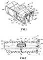
- an adapterin the form of an adapter, generally designated 10, which includes a housing, generally designated 12, and a pair of shutter members 14 pivotally mounted on the housing.
- an adapterthe concepts of the invention are equally applicable for a wide range of receptacles for receiving a fiber optic connector or other optical fiber transmission device along an optic axis. Therefore, the term "fiber optic connector" is used herein and in the claims hereof in a generic sense to include a variety of optical fiber transmission devices.
- adapter housing 12is generally rectangular in cross-section and includes two parts 12a and 12b adhered together at a joint 16 so that the housing is a unitary structure. As seen best in Figure 2, both housing parts have abutting interior cross walls 18 and aligned interior cylindrical bosses 20 which receive the projecting ferrules of a pair of fiber optic connectors so that the encapsulated fibers are connected end-to-end along an optic axis 22.
- the unitary housingdefines a forward open end 24 for receiving a first fiber optic connector in the direction of arrow "A”, and a rear open end 26 (Fig. 2) in a rear end face 28 for receiving a second or mating fiber optic connector in the direction of arrow "B".
- a metal latch member 30having a pair of side flexible latch arms 32 may be provided on housing 12 for mounting the adapter in an opening in a panel or the like.
- adapter 10is a double-ended receptacle for interconnecting two pairs of mating fiber optic connectors.
- a front face 34 of housing 12has a pair of the forward open ends 24 which expose a pair of through passages 36 extending through the housing and closable by shutter members 14.
- Each passage 36has cross walls 18 and cylindrical bosses 20 therein as described above in relation to Figure 2.
- Each shutter member 14includes a pair of apertured bosses 38 aligned with apertured bosses 40 at a top edge of the forward open end of housing 12.
- a pivot rod 42extends through the aligned apertured bosses 38 and 40 of the shutter members and the housing, respectively, so that the shutter members are pivotally movable to close and open the open end of the housing.
- Figure 1shows both shutter members in their closed position whereby the shutter members extend across optic axes 22 (Fig. 2).
- a pair of coil springsare wrapped around pivot rod 42 and include first ends 44 engaging a top wall 46 of the housing and opposite ends 48 for engaging shutter members 14. The springs bias the shutter members toward their closed positions as shown in Figure 1.
- Top wall 46 of the housingforms an outside wall extending rearwardly from forward open end 24 of the housing.
- the top wallis generally flat, and each shutter member is generally planar or flat.
- Figures 3-5show one of the shutter members 14 (the left-hand shutter member in the drawings) being pivoted upwardly and away from its closed position of Figure 1. Specifically, in the closed position shown in Figures 1 and 2, the shutter members extend transversely across optic axis 22 to close the forward open end of the housing.
- Figure 3shows the one shutter member pivoted upwardly about pivot rod 42 in the direction of arrow "C" to a position approximately 90° away from its closed position.
- Figure 4shows the one shutter member 14 pivoted further to an upwardly extended position approximately 180° from its closed position of Figure 1.
- Figure 5shows the one shutter member 14 pivoted all the way to its maximum open position whereat the shutter member is juxtaposed against rearwardly extending outside wall 46 of housing 12.
Landscapes
- Physics & Mathematics (AREA)
- General Physics & Mathematics (AREA)
- Optics & Photonics (AREA)
- Mechanical Coupling Of Light Guides (AREA)
- Connector Housings Or Holding Contact Members (AREA)
- Light Guides In General And Applications Therefor (AREA)
Abstract
Description
Claims (21)
- A receptacle (10) for receiving a fiber optic connector along an opticaxis (22), comprising:a housing (12) having a forward open end (24) for receiving the fiber opticconnector inserted thereinto on said optic axis (22) and an outside wall (46) extendingrearwardly from the open end (24); anda shutter member (14) pivotally mounted on the housing (12) adjacent to saidopen end (24) and being pivotally movable to close and open said open end, theshutter member extending across the optic axis (22) when the shutter member isclosed, and the shutter member being pivotable away from the optic axis to a positionjuxtaposed against said rearwardly extending outside wall (46).
- The receptacle of claim 1 wherein said housing (12) is sized andshaped for grasping between an operator's thumb and forefinger with the shuttermember (14) pinched against said rearwardly extending outside wall (46).
- The receptacle of claim 1 wherein said shutter member (14) isgenerally planar.
- The receptacle of claim 3 wherein said rearwardly extending outsidewall (46) is generally flat.
- The receptacle of claim 1 wherein said shutter member (14) isgenerally rectangular.
- The receptacle of claim 5 wherein said forward open end (24) of thehousing (12) is generally rectangular.
- The receptacle of claim 6 wherein said shutter member (14) is pivotallymounted on the housing at one edge of the generally rectangular open end (24).
- The receptacle of claim 1 wherein said housing includes a pair of saidforward open ends (24) in side-by-side relationship, with one of said shutter members(14) independently pivotally mounted on the housing adjacent each open end.
- The receptacle of claim 1 wherein said receptacle comprises an adapter(10) having said open end (24) at one end thereof and an end face (28) at an oppositeend thereof for mating with an associated fiber optic transmission means.
- A receptacle (10) for receiving a fiber optic connector along an opticaxis (22), comprising:a housing (12) having a generally rectangular forward open end (24) forreceiving the fiber optic connector inserted thereinto on said optic axis (22) and agenerally flat outside wall (46) extending rearwardly from the open end; anda generally rectangular, generally planar shutter member (14) pivotallymounted on the housing (12) at one edge of the generally rectangular open end (24)and being pivotally movable to close and open said open end, the shutter member (14)extending across the optic axis (22) when the shutter member is closed, and theshutter member being pivotable away from the optic axis to a position juxtaposedagainst said rearwardly extending outside wall (46).
- The receptacle of claim 10 wherein said housing (12) is sized andshaped for grasping between an operator's thumb and forefinger with the shuttermember (14) pinched against said rearwardly extending outside wall (46).
- The receptacle of claim 10 wherein said receptacle comprises anadapter (10) having said open end (24) at one end thereof and an end face (28) at anopposite end thereof for mating with an associated fiber optic transmission means.
- The receptacle of claim 10 wherein said housing includes a pair of saidforward open ends (24) in side-by-side relationship, with one of said shutter members(14) independently pivotally mounted on the housing adjacent each open end.
- A receptacle (10) for receiving a fiber optic connector along an opticaxis (22), comprising:a housing (12) having an open end (24) for receiving the fiber optic connectorinserted thereinto on said optic axis (22); anda shutter member (14) pivotally mounted on the housing (12) adjacent to saidopen end (24) and being pivotally movable to close and open said open end, theshutter member (14) extending across the optic axis (22) when the shutter member isin a closed position, and the shutter member (14) being pivotable approximately 270°away from said closed position to an open position.
- The receptacle of claim 14 wherein said shutter member (14) isgenerally rectangular.
- The receptacle of claim 15 wherein said forward open end (24) of thehousing (12) is generally rectangular.
- The receptacle of claim 16 wherein said shutter member (14) ispivotally mounted on the housing at one edge of the generally rectangular open end(24).
- The receptacle of claim 15 wherein said shutter member (14) isgenerally planar.
- The receptacle of claim 14 wherein said housing includes a pair of saidforward open ends (24) in side-by-side relationship, with one of said shutter members(14) independently pivotally mounted on the housing adjacent each open end.
- The receptacle of claim 14 wherein said receptacle comprises anadapter (10) having said open end (24) at one end thereof and an end face (28) at anopposite end thereof for mating with an associated fiber optic transmission means.
- The receptacle of claim 14 wherein said housing (12) is sized andshaped for grasping between an operator's thumb and forefinger with the shuttermember (14) pinched against the outside of the housing.
Applications Claiming Priority (2)
| Application Number | Priority Date | Filing Date | Title |
|---|---|---|---|
| US677376 | 2000-09-18 | ||
| US09/677,376US6425694B1 (en) | 2000-09-18 | 2000-09-18 | Fiber optic receptacle with protective shutter |
Publications (3)
| Publication Number | Publication Date |
|---|---|
| EP1189085A2true EP1189085A2 (en) | 2002-03-20 |
| EP1189085A3 EP1189085A3 (en) | 2004-08-11 |
| EP1189085B1 EP1189085B1 (en) | 2010-04-28 |
Family
ID=24718446
Family Applications (1)
| Application Number | Title | Priority Date | Filing Date |
|---|---|---|---|
| EP01120584AExpired - LifetimeEP1189085B1 (en) | 2000-09-18 | 2001-08-29 | Fiber optic receptacle with protective shutter |
Country Status (7)
| Country | Link |
|---|---|
| US (1) | US6425694B1 (en) |
| EP (1) | EP1189085B1 (en) |
| JP (2) | JP2002148483A (en) |
| KR (1) | KR100418841B1 (en) |
| CN (1) | CN1196950C (en) |
| DE (1) | DE60141936D1 (en) |
| TW (1) | TW530953U (en) |
Cited By (8)
| Publication number | Priority date | Publication date | Assignee | Title |
|---|---|---|---|---|
| WO2016156643A1 (en)* | 2015-03-27 | 2016-10-06 | De Dios Martín Longinos | Cover assembly for a jack receptacle |
| CN113219596A (en)* | 2021-04-30 | 2021-08-06 | 深圳市中葛科技有限公司 | Double-optical-fiber butt-joint adapter |
| US11342718B2 (en) | 2015-03-27 | 2022-05-24 | CommScope Connectivity Spain, S.L. | Latch for telecommunications connector |
| US11356751B2 (en) | 2017-06-19 | 2022-06-07 | Commscope Technologies Llc | High density bezel for patch panel |
| US11356752B2 (en) | 2017-11-10 | 2022-06-07 | Commscope Technologies Llc | Telecommunications panel with grounding wire |
| US11367985B2 (en) | 2016-08-15 | 2022-06-21 | Commscope Technologies Llc | Connector assembly with grounding |
| US11509105B2 (en) | 2015-03-20 | 2022-11-22 | CommScope Connectivity Spain, S.L. | Connector with separable lacing fixture |
| EP4579303A1 (en)* | 2023-12-28 | 2025-07-02 | Altice Labs, S.A. | Bale-clasp cover mechanism for a pluggable optical transceiver using a single or duplex lucent connector |
Families Citing this family (139)
| Publication number | Priority date | Publication date | Assignee | Title |
|---|---|---|---|---|
| US5883995A (en) | 1997-05-20 | 1999-03-16 | Adc Telecommunications, Inc. | Fiber connector and adapter |
| US6760531B1 (en) | 1999-03-01 | 2004-07-06 | Adc Telecommunications, Inc. | Optical fiber distribution frame with outside plant enclosure |
| US6471412B1 (en)* | 2000-02-04 | 2002-10-29 | Molex Incorporated | Fiber optic connector receptacle |
| CN1398232A (en)* | 2000-02-07 | 2003-02-19 | 特赫鲁赫鲁器材有限公司 | Portable-pente ski tow |
| TW495624B (en)* | 2000-02-25 | 2002-07-21 | Sharp Kk | Light transmission device |
| USD476625S1 (en) | 2001-03-14 | 2003-07-01 | Honda Tsushin Kogyo Co. Ltd. | Light connector with a shutter |
| USD476626S1 (en) | 2001-03-14 | 2003-07-01 | Honda Tsushin Kogyo Co. Ltd. | Light connector with a shutter (double vertical type) |
| USD476624S1 (en) | 2001-03-14 | 2003-07-01 | Honda Tsushin Kogyo Co. Ltd. | Light connector with a shutter (double horizontal type) |
| US6688780B2 (en) | 2002-02-07 | 2004-02-10 | Amphenol Corporation | Cantilevered shutter for optical adapter |
| US6715930B2 (en)* | 2002-03-21 | 2004-04-06 | Lucent Technologies Inc. | Optical fiber shutter adapter with protective door |
| US6702477B1 (en)* | 2002-09-23 | 2004-03-09 | Fci Americas Technology, Inc. | Adapter with cap for fiber optic connector |
| US7869171B2 (en) | 2003-12-02 | 2011-01-11 | Pass & Seymour, Inc. | Protective electrical wiring device with a center nightlight |
| JP4181895B2 (en) | 2003-02-25 | 2008-11-19 | 日本圧着端子製造株式会社 | Receptacle |
| US6715928B1 (en)* | 2003-02-27 | 2004-04-06 | Molex Incorporated | Connector panel mount system |
| US7142764B2 (en) | 2003-03-20 | 2006-11-28 | Tyco Electronics Corporation | Optical fiber interconnect cabinets, termination modules and fiber connectivity management for the same |
| US7198409B2 (en)* | 2003-06-30 | 2007-04-03 | Adc Telecommunications, Inc. | Fiber optic connector holder and method |
| US7233731B2 (en)* | 2003-07-02 | 2007-06-19 | Adc Telecommunications, Inc. | Telecommunications connection cabinet |
| US7312963B1 (en)* | 2003-12-05 | 2007-12-25 | Pass & Seymour, Inc. | Protective device with tamper resistant shutters |
| US6969801B2 (en)* | 2003-08-21 | 2005-11-29 | Pass & Seymour, Inc. | Shuttered receptacle for a protective device |
| US7369741B2 (en)* | 2003-11-17 | 2008-05-06 | Fiber Optics Network Solutions Corp. | Storage adapter with dust cap posts |
| US6983095B2 (en)* | 2003-11-17 | 2006-01-03 | Fiber Optic Network Solutions Corporation | Systems and methods for managing optical fibers and components within an enclosure in an optical communications network |
| US20050111796A1 (en)* | 2003-11-26 | 2005-05-26 | Matasek Jeffrey A. | Adaptor for reducing EMI |
| US8044299B2 (en)* | 2003-12-05 | 2011-10-25 | Pass & Seymour, Inc. | Protective device with tamper resistant shutters |
| US7218827B2 (en) | 2004-06-18 | 2007-05-15 | Adc Telecommunications, Inc. | Multi-position fiber optic connector holder and method |
| US7340146B2 (en)* | 2005-03-10 | 2008-03-04 | Yazaki Corporation | Dust shutter for an optical adapter |
| US7194181B2 (en) | 2005-03-31 | 2007-03-20 | Adc Telecommunications, Inc. | Adapter block including connector storage |
| US7623749B2 (en)* | 2005-08-30 | 2009-11-24 | Adc Telecommunications, Inc. | Fiber distribution hub with modular termination blocks |
| US7720343B2 (en) | 2006-02-13 | 2010-05-18 | Adc Telecommunications, Inc. | Fiber distribution hub with swing frame and modular termination panels |
| US7816602B2 (en) | 2006-02-13 | 2010-10-19 | Adc Telecommunications, Inc. | Fiber distribution hub with outside accessible grounding terminals |
| US7572066B2 (en)* | 2006-03-14 | 2009-08-11 | Corning Cable Systems Llc | Translucent dust cap for fiber optic adapter |
| US7760984B2 (en)* | 2006-05-04 | 2010-07-20 | Adc Telecommunications, Inc. | Fiber distribution hub with swing frame and wrap-around doors |
| TW200817105A (en)* | 2006-08-18 | 2008-04-16 | Akrion Technologies Inc | System and method for processing a substrate utilizing a gas stream for particle removal |
| US7496268B2 (en)* | 2006-12-13 | 2009-02-24 | Corning Cable Systems Llc | High density fiber optic hardware |
| US7822310B2 (en) | 2007-02-28 | 2010-10-26 | Corning Cable Systems Llc | Fiber optic splice trays |
| FR2916090B1 (en)* | 2007-05-11 | 2009-07-17 | Legrand France | SEALED ELECTRICAL CONNECTION DEVICE WITH MULTIPLE CONFIGURATIONS |
| US7945139B2 (en)* | 2007-06-13 | 2011-05-17 | Corning Cable Systems Llc | Dust cap for fiber optic adapter |
| JP4863393B2 (en)* | 2007-06-20 | 2012-01-25 | サンコール株式会社 | Shutter assembly |
| JP4780794B2 (en)* | 2007-06-20 | 2011-09-28 | サンコール株式会社 | Shutter assembly |
| JP4986289B2 (en)* | 2007-07-04 | 2012-07-25 | 株式会社正電社 | Optical connector dustproof shutter device and connector adapter used therefor |
| US8798427B2 (en) | 2007-09-05 | 2014-08-05 | Corning Cable Systems Llc | Fiber optic terminal assembly |
| US7686518B2 (en)* | 2007-09-19 | 2010-03-30 | Commscope, Inc. Of North Carolina | Shuttered adapter |
| US8229265B2 (en) | 2007-11-21 | 2012-07-24 | Adc Telecommunications, Inc. | Fiber distribution hub with multiple configurations |
| JP5072610B2 (en)* | 2008-01-10 | 2012-11-14 | 株式会社エネルギア・コミュニケーションズ | Optical connector cover and optical wiring board using optical connector cover |
| US7889961B2 (en) | 2008-03-27 | 2011-02-15 | Corning Cable Systems Llc | Compact, high-density adapter module, housing assembly and frame assembly for optical fiber telecommunications |
| ES2560802T3 (en) | 2008-08-27 | 2016-02-22 | Adc Telecommunications, Inc. | Fiber optic adapter with integrally molded bushing alignment structure |
| US8452148B2 (en) | 2008-08-29 | 2013-05-28 | Corning Cable Systems Llc | Independently translatable modules and fiber optic equipment trays in fiber optic equipment |
| US11294136B2 (en) | 2008-08-29 | 2022-04-05 | Corning Optical Communications LLC | High density and bandwidth fiber optic apparatuses and related equipment and methods |
| CN102209921B (en) | 2008-10-09 | 2015-11-25 | 康宁光缆系统有限公司 | There is the fibre-optic terminus supported from the adapter panel of the input and output optical fiber of optical splitters |
| US8879882B2 (en) | 2008-10-27 | 2014-11-04 | Corning Cable Systems Llc | Variably configurable and modular local convergence point |
| WO2010059623A1 (en) | 2008-11-21 | 2010-05-27 | Adc Telecommunications, Inc. | Fiber optic telecommunications module |
| EP2221932B1 (en) | 2009-02-24 | 2011-11-16 | CCS Technology Inc. | Holding device for a cable or an assembly for use with a cable |
| EP2237091A1 (en) | 2009-03-31 | 2010-10-06 | Corning Cable Systems LLC | Removably mountable fiber optic terminal |
| US8699838B2 (en) | 2009-05-14 | 2014-04-15 | Ccs Technology, Inc. | Fiber optic furcation module |
| US9075216B2 (en) | 2009-05-21 | 2015-07-07 | Corning Cable Systems Llc | Fiber optic housings configured to accommodate fiber optic modules/cassettes and fiber optic panels, and related components and methods |
| US8538226B2 (en) | 2009-05-21 | 2013-09-17 | Corning Cable Systems Llc | Fiber optic equipment guides and rails configured with stopping position(s), and related equipment and methods |
| US8712206B2 (en) | 2009-06-19 | 2014-04-29 | Corning Cable Systems Llc | High-density fiber optic modules and module housings and related equipment |
| WO2010148325A1 (en) | 2009-06-19 | 2010-12-23 | Corning Cable Systems Llc | High fiber optic cable packing density apparatus |
| EP2443497B1 (en) | 2009-06-19 | 2020-03-04 | Corning Cable Systems LLC | High density and bandwidth fiber optic apparatus |
| US8348517B2 (en)* | 2009-08-13 | 2013-01-08 | Commscope, Inc. Of North Carolina | Shutter for a fiber optic component and a fiber optic component including the shutter |
| US8467651B2 (en) | 2009-09-30 | 2013-06-18 | Ccs Technology Inc. | Fiber optic terminals configured to dispose a fiber optic connection panel(s) within an optical fiber perimeter and related methods |
| US8625950B2 (en) | 2009-12-18 | 2014-01-07 | Corning Cable Systems Llc | Rotary locking apparatus for fiber optic equipment trays and related methods |
| CN102116909B (en)* | 2010-01-04 | 2012-09-05 | 泰科电子(上海)有限公司 | Safety device for optical fiber adapter interface |
| US8992099B2 (en) | 2010-02-04 | 2015-03-31 | Corning Cable Systems Llc | Optical interface cards, assemblies, and related methods, suited for installation and use in antenna system equipment |
| CN102870021B (en) | 2010-03-02 | 2015-03-11 | 蒂安电子服务有限责任公司 | Fibre-optic telecommunication module |
| US9547144B2 (en) | 2010-03-16 | 2017-01-17 | Corning Optical Communications LLC | Fiber optic distribution network for multiple dwelling units |
| US8727636B2 (en)* | 2010-03-19 | 2014-05-20 | Corning Incorporated | Fiber optic interface device with positionable cleaning cover |
| US8579518B2 (en)* | 2010-03-19 | 2013-11-12 | Corning Incorporated | Optical receptacles and systems and devices including optical receptacles |
| US8913866B2 (en) | 2010-03-26 | 2014-12-16 | Corning Cable Systems Llc | Movable adapter panel |
| CA2796221C (en) | 2010-04-16 | 2018-02-13 | Ccs Technology, Inc. | Sealing and strain relief device for data cables |
| US8792767B2 (en) | 2010-04-16 | 2014-07-29 | Ccs Technology, Inc. | Distribution device |
| EP2381284B1 (en) | 2010-04-23 | 2014-12-31 | CCS Technology Inc. | Under floor fiber optic distribution device |
| US8879881B2 (en) | 2010-04-30 | 2014-11-04 | Corning Cable Systems Llc | Rotatable routing guide and assembly |
| US9632270B2 (en) | 2010-04-30 | 2017-04-25 | Corning Optical Communications LLC | Fiber optic housings configured for tool-less assembly, and related components and methods |
| US8705926B2 (en) | 2010-04-30 | 2014-04-22 | Corning Optical Communications LLC | Fiber optic housings having a removable top, and related components and methods |
| US9720195B2 (en) | 2010-04-30 | 2017-08-01 | Corning Optical Communications LLC | Apparatuses and related components and methods for attachment and release of fiber optic housings to and from an equipment rack |
| US9075217B2 (en) | 2010-04-30 | 2015-07-07 | Corning Cable Systems Llc | Apparatuses and related components and methods for expanding capacity of fiber optic housings |
| US8660397B2 (en) | 2010-04-30 | 2014-02-25 | Corning Cable Systems Llc | Multi-layer module |
| US9519118B2 (en) | 2010-04-30 | 2016-12-13 | Corning Optical Communications LLC | Removable fiber management sections for fiber optic housings, and related components and methods |
| US8718436B2 (en) | 2010-08-30 | 2014-05-06 | Corning Cable Systems Llc | Methods, apparatuses for providing secure fiber optic connections |
| CH703705A1 (en) | 2010-09-15 | 2012-03-15 | Huber+Suhner Ag | Clutch for fiber optic connectors. |
| WO2012054454A2 (en) | 2010-10-19 | 2012-04-26 | Corning Cable Systems Llc | Transition box for multiple dwelling unit fiber optic distribution network |
| US9279951B2 (en) | 2010-10-27 | 2016-03-08 | Corning Cable Systems Llc | Fiber optic module for limited space applications having a partially sealed module sub-assembly |
| US8662760B2 (en) | 2010-10-29 | 2014-03-04 | Corning Cable Systems Llc | Fiber optic connector employing optical fiber guide member |
| US9116324B2 (en) | 2010-10-29 | 2015-08-25 | Corning Cable Systems Llc | Stacked fiber optic modules and fiber optic equipment configured to support stacked fiber optic modules |
| CA2819235C (en) | 2010-11-30 | 2018-01-16 | Corning Cable Systems Llc | Fiber device holder and strain relief device |
| WO2012106510A2 (en) | 2011-02-02 | 2012-08-09 | Corning Cable Systems Llc | Dense fiber optic connector assemblies and related connectors and cables suitable for establishing optical connections for optical backplanes in equipment racks |
| US9008485B2 (en) | 2011-05-09 | 2015-04-14 | Corning Cable Systems Llc | Attachment mechanisms employed to attach a rear housing section to a fiber optic housing, and related assemblies and methods |
| AU2012275598A1 (en) | 2011-06-30 | 2014-01-16 | Corning Optical Communications LLC | Fiber optic equipment assemblies employing non-U-width-sized housings and related methods |
| US8953924B2 (en) | 2011-09-02 | 2015-02-10 | Corning Cable Systems Llc | Removable strain relief brackets for securing fiber optic cables and/or optical fibers to fiber optic equipment, and related assemblies and methods |
| US9417418B2 (en) | 2011-09-12 | 2016-08-16 | Commscope Technologies Llc | Flexible lensed optical interconnect device for signal distribution |
| RU2611105C2 (en) | 2011-10-07 | 2017-02-21 | Адс Телекоммьюникейшнз, Инк. | Fibre-optic cartridge, system and method |
| US9196997B2 (en)* | 2011-11-10 | 2015-11-24 | Panduit Corp. | Shuttered LC adapter |
| US9038832B2 (en) | 2011-11-30 | 2015-05-26 | Corning Cable Systems Llc | Adapter panel support assembly |
| US9219546B2 (en) | 2011-12-12 | 2015-12-22 | Corning Optical Communications LLC | Extremely high frequency (EHF) distributed antenna systems, and related components and methods |
| US8620123B2 (en) | 2012-02-13 | 2013-12-31 | Corning Cable Systems Llc | Visual tracer system for fiber optic cable |
| WO2013126068A1 (en) | 2012-02-24 | 2013-08-29 | Hewlett-Packard Development Company, L.P. | Optical blind-mate connector |
| US10110307B2 (en) | 2012-03-02 | 2018-10-23 | Corning Optical Communications LLC | Optical network units (ONUs) for high bandwidth connectivity, and related components and methods |
| US8882519B2 (en) | 2012-03-28 | 2014-11-11 | Tyco Electronics Uk Ltd. | Dust cap for a telecommunications connector |
| US8568152B1 (en) | 2012-04-19 | 2013-10-29 | Pass & Seymour, Inc. | Shutter assembly for electrical devices |
| US9004778B2 (en) | 2012-06-29 | 2015-04-14 | Corning Cable Systems Llc | Indexable optical fiber connectors and optical fiber connector arrays |
| US9250409B2 (en) | 2012-07-02 | 2016-02-02 | Corning Cable Systems Llc | Fiber-optic-module trays and drawers for fiber-optic equipment |
| US9049500B2 (en) | 2012-08-31 | 2015-06-02 | Corning Cable Systems Llc | Fiber optic terminals, systems, and methods for network service management |
| US9042702B2 (en) | 2012-09-18 | 2015-05-26 | Corning Cable Systems Llc | Platforms and systems for fiber optic cable attachment |
| US9146362B2 (en) | 2012-09-21 | 2015-09-29 | Adc Telecommunications, Inc. | Insertion and removal tool for a fiber optic ferrule alignment sleeve |
| NZ706687A (en) | 2012-09-28 | 2017-09-29 | Adc Telecommunications Inc | Fiber optic cassette |
| US9146374B2 (en) | 2012-09-28 | 2015-09-29 | Adc Telecommunications, Inc. | Rapid deployment packaging for optical fiber |
| US9223094B2 (en) | 2012-10-05 | 2015-12-29 | Tyco Electronics Nederland Bv | Flexible optical circuit, cassettes, and methods |
| US8909019B2 (en) | 2012-10-11 | 2014-12-09 | Ccs Technology, Inc. | System comprising a plurality of distribution devices and distribution device |
| ES2551077T3 (en) | 2012-10-26 | 2015-11-16 | Ccs Technology, Inc. | Fiber optic management unit and fiber optic distribution device |
| US8985862B2 (en) | 2013-02-28 | 2015-03-24 | Corning Cable Systems Llc | High-density multi-fiber adapter housings |
| US9435975B2 (en) | 2013-03-15 | 2016-09-06 | Commscope Technologies Llc | Modular high density telecommunications frame and chassis system |
| US9798092B2 (en)* | 2013-09-30 | 2017-10-24 | Hewlett Packard Enterprise Development Lp | Optical blind-mate connector and adapter |
| WO2015116672A1 (en) | 2014-01-28 | 2015-08-06 | Adc Telecommunications, Inc. | Slidable fiber optic connection module with cable slack management |
| US9494758B2 (en) | 2014-04-03 | 2016-11-15 | Commscope Technologies Llc | Fiber optic distribution system |
| WO2016068892A1 (en)* | 2014-10-29 | 2016-05-06 | Hewlett Packard Enterprise Development Lp | Optical connector assembly apparatus |
| US10379309B2 (en) | 2014-11-18 | 2019-08-13 | Corning Optical Communications LLC | Traceable optical fiber cable and filtered viewing device for enhanced traceability |
| US10228526B2 (en) | 2015-03-31 | 2019-03-12 | Corning Optical Communications LLC | Traceable cable with side-emitting optical fiber and method of forming the same |
| MX2017014377A (en) | 2015-05-15 | 2018-08-15 | Adc Telecommunications Shanghai Distrib Co Ltd | Alignment sleeve assembly and optical fibre adapter. |
| US10101553B2 (en) | 2015-05-20 | 2018-10-16 | Corning Optical Communications LLC | Traceable cable with side-emitting optical fiber and method of forming the same |
| CN105161905B (en)* | 2015-06-28 | 2017-06-27 | 中航光电科技股份有限公司 | Dust-proof mechanism of the socket |
| EP3325876A1 (en) | 2015-07-17 | 2018-05-30 | Corning Optical Communications LLC | Systems and methods for traceable cables |
| EP3326014A1 (en) | 2015-07-17 | 2018-05-30 | Corning Optical Communications LLC | Systems and methods for tracing cables and cables for such systems and methods |
| US10101545B2 (en) | 2015-10-30 | 2018-10-16 | Corning Optical Communications LLC | Traceable cable assembly and connector |
| AU2016352929B2 (en) | 2015-11-13 | 2021-07-29 | CommScope Connectivity Belgium BVBA | Adapter shutter with integrated connector lock |
| WO2017100114A1 (en)* | 2015-12-08 | 2017-06-15 | Panduit Corp. | Rj45 shuttered jacks and related communication systems |
| CN109154701A (en) | 2016-04-08 | 2019-01-04 | 康宁研究与开发公司 | With light structures and for carrying the traceable fiber optical cable assembly from the tracking optical fiber of the received light of light originating device |
| US10107983B2 (en) | 2016-04-29 | 2018-10-23 | Corning Optical Communications LLC | Preferential mode coupling for enhanced traceable patch cord performance |
| US10409007B2 (en)* | 2016-05-02 | 2019-09-10 | Commscope Technologies Llc | Optical connector and adapter |
| TWI608261B (en)* | 2016-11-29 | 2017-12-11 | 普泰光電股份有限公司 | Optical fiber adapter with shutter member |
| US10222560B2 (en) | 2016-12-21 | 2019-03-05 | Corning Research & Development Corporation | Traceable fiber optic cable assembly with fiber guide and tracing optical fibers for carrying light received from a light launch device |
| US10234614B2 (en) | 2017-01-20 | 2019-03-19 | Corning Research & Development Corporation | Light source assemblies and systems and methods with mode homogenization |
| US11409068B2 (en) | 2017-10-02 | 2022-08-09 | Commscope Technologies Llc | Fiber optic circuit and preparation method |
| US10539758B2 (en) | 2017-12-05 | 2020-01-21 | Corning Research & Development Corporation | Traceable fiber optic cable assembly with indication of polarity |
| US10539747B2 (en) | 2017-12-05 | 2020-01-21 | Corning Research & Development Corporation | Bend induced light scattering fiber and cable assemblies and method of making |
| CN108832370B (en) | 2018-09-21 | 2024-06-18 | 新确精密科技(深圳)有限公司 | Adapter |
| US10424863B1 (en) | 2018-11-13 | 2019-09-24 | Eaton Intelligent Power Limited | Electrical receptacle and tamper-resistant shutter assembly therefor |
| EP4004619A4 (en) | 2019-07-26 | 2023-08-09 | CommScope Technologies LLC | FIBER OPTIC ADAPTERS CONVERTIBLE BETWEEN DIFFERENT TYPES OF POLARITY |
| US12339511B2 (en) | 2020-03-31 | 2025-06-24 | Commscope Technologies Llc | Fiber optic cable management systems and methods |
| CN118502035B (en)* | 2024-07-03 | 2025-02-18 | 联纲光电科技股份有限公司 | Detachable multimedia plug for AOC active optical cable |
Family Cites Families (11)
| Publication number | Priority date | Publication date | Assignee | Title |
|---|---|---|---|---|
| US4779950A (en)* | 1984-04-03 | 1988-10-25 | Thomas & Betts Corporation | Connection apparatus for optical fibers |
| JPH06331859A (en)* | 1993-05-25 | 1994-12-02 | Sharp Corp | Light transmission device and its production |
| US5506922A (en)* | 1994-08-01 | 1996-04-09 | Molex Incorporated | Fiber optic component assembly with a movable protective shield |
| US5687268A (en)* | 1995-11-27 | 1997-11-11 | Lucent Technologies Inc. | Pivotable optical shutter for blocking emission from a lightguide adapter #5 |
| US5956444A (en)* | 1997-02-13 | 1999-09-21 | Amphenol Corporation | Radiation absorbing shield for fiber optic systems |
| US6041155A (en)* | 1997-12-10 | 2000-03-21 | Lucent Technologies Inc. | Universal dust cover |
| US6004043A (en)* | 1997-12-19 | 1999-12-21 | The Whitaker Corporation | Shuttered connector receptacle |
| US6081647A (en)* | 1998-01-05 | 2000-06-27 | Molex Incorporated | Fiber optic connector receptacle |
| US6108482A (en)* | 1998-01-14 | 2000-08-22 | Molex Incorporated | Fiber optic connector receptacle |
| US6079881A (en)* | 1998-04-08 | 2000-06-27 | Molex Incorporated | Fiber optic connector receptacle assembly |
| US6240229B1 (en)* | 1998-12-21 | 2001-05-29 | Molex Incorporated | Connector assembly |
- 2000
- 2000-09-18USUS09/677,376patent/US6425694B1/ennot_activeExpired - Lifetime
- 2001
- 2001-08-29EPEP01120584Apatent/EP1189085B1/ennot_activeExpired - Lifetime
- 2001-08-29DEDE60141936Tpatent/DE60141936D1/ennot_activeExpired - Lifetime
- 2001-09-14JPJP2001279102Apatent/JP2002148483A/enactivePending
- 2001-09-17KRKR10-2001-0057139Apatent/KR100418841B1/ennot_activeExpired - Fee Related
- 2001-09-17CNCNB011406011Apatent/CN1196950C/ennot_activeExpired - Fee Related
- 2001-09-19TWTW090216004Upatent/TW530953U/ennot_activeIP Right Cessation
- 2004
- 2004-05-11JPJP2004002583Upatent/JP3105127U/ennot_activeExpired - Lifetime
Cited By (15)
| Publication number | Priority date | Publication date | Assignee | Title |
|---|---|---|---|---|
| US11509105B2 (en) | 2015-03-20 | 2022-11-22 | CommScope Connectivity Spain, S.L. | Connector with separable lacing fixture |
| US10522939B2 (en) | 2015-03-27 | 2019-12-31 | CommScope Connectivity Spain, S.L. | Cover assembly for a telecommunications connector |
| US10958012B2 (en) | 2015-03-27 | 2021-03-23 | CommScope Connectivity Spain, S.L. | Cover assembly for a telecommunications connector |
| US12355196B2 (en) | 2015-03-27 | 2025-07-08 | CommScope Connectivity Spain, S.L. | Latch for telecommunications connector |
| US12206205B2 (en) | 2015-03-27 | 2025-01-21 | CommScope Connectivity Spain, S.L. | Cover assembly for a telecommunications connector |
| US11342718B2 (en) | 2015-03-27 | 2022-05-24 | CommScope Connectivity Spain, S.L. | Latch for telecommunications connector |
| WO2016156643A1 (en)* | 2015-03-27 | 2016-10-06 | De Dios Martín Longinos | Cover assembly for a jack receptacle |
| US12149032B2 (en) | 2016-08-15 | 2024-11-19 | Commscope Technologies Llc | Connector assembly with grounding |
| US11367985B2 (en) | 2016-08-15 | 2022-06-21 | Commscope Technologies Llc | Connector assembly with grounding |
| US11356751B2 (en) | 2017-06-19 | 2022-06-07 | Commscope Technologies Llc | High density bezel for patch panel |
| US11838700B2 (en) | 2017-06-19 | 2023-12-05 | Commscope Technologies Llc | High density bezel for patch panel |
| US11356752B2 (en) | 2017-11-10 | 2022-06-07 | Commscope Technologies Llc | Telecommunications panel with grounding wire |
| CN113219596B (en)* | 2021-04-30 | 2022-04-01 | 深圳市中葛科技有限公司 | Double-optical-fiber butt-joint adapter |
| CN113219596A (en)* | 2021-04-30 | 2021-08-06 | 深圳市中葛科技有限公司 | Double-optical-fiber butt-joint adapter |
| EP4579303A1 (en)* | 2023-12-28 | 2025-07-02 | Altice Labs, S.A. | Bale-clasp cover mechanism for a pluggable optical transceiver using a single or duplex lucent connector |
Also Published As
| Publication number | Publication date |
|---|---|
| EP1189085B1 (en) | 2010-04-28 |
| KR100418841B1 (en) | 2004-02-14 |
| KR20020022011A (en) | 2002-03-23 |
| US6425694B1 (en) | 2002-07-30 |
| CN1196950C (en) | 2005-04-13 |
| CN1344946A (en) | 2002-04-17 |
| EP1189085A3 (en) | 2004-08-11 |
| TW530953U (en) | 2003-05-01 |
| JP2002148483A (en) | 2002-05-22 |
| JP3105127U (en) | 2004-10-21 |
| DE60141936D1 (en) | 2010-06-10 |
Similar Documents
| Publication | Publication Date | Title |
|---|---|---|
| US6425694B1 (en) | Fiber optic receptacle with protective shutter | |
| US6471412B1 (en) | Fiber optic connector receptacle | |
| EP0930521B1 (en) | Fiber optic connector receptacle | |
| EP0697607B1 (en) | Fiber optic component assembly with a movable protective shield | |
| EP1014126B1 (en) | Connector assembly | |
| JP3565191B2 (en) | Optical connector device and dustproof cover thereof | |
| US6076975A (en) | Fiber optic connector assembly | |
| US5825955A (en) | Fiber optic diversion connector | |
| US20040141693A1 (en) | Fiber optic connector assembly | |
| EP0949522B1 (en) | Fiber optic connector receptacle assembly | |
| US4872736A (en) | Connector assembly having a latching mechanism | |
| CA2461022C (en) | Fiber optic plug | |
| EP0788002A1 (en) | Fiber optic connector receptacle with protective shutter | |
| US11754789B2 (en) | Fiber optic connector with unitary housing and fiber optic connector assembly | |
| WO2019055820A1 (en) | Fiber optic connector with boot-integrated release and related assemblies | |
| US6505976B1 (en) | Alignment pin assembly for fiber optic connectors | |
| US5887098A (en) | Fiber optic adapter with protective shield | |
| US20090264021A1 (en) | Connection device |
Legal Events
| Date | Code | Title | Description |
|---|---|---|---|
| PUAI | Public reference made under article 153(3) epc to a published international application that has entered the european phase | Free format text:ORIGINAL CODE: 0009012 | |
| AK | Designated contracting states | Kind code of ref document:A2 Designated state(s):AT BE CH CY DE DK ES FI FR GB GR IE IT LI LU MC NL PT SE TR | |
| AX | Request for extension of the european patent | Free format text:AL;LT;LV;MK;RO;SI | |
| PUAL | Search report despatched | Free format text:ORIGINAL CODE: 0009013 | |
| AK | Designated contracting states | Kind code of ref document:A3 Designated state(s):AT BE CH CY DE DK ES FI FR GB GR IE IT LI LU MC NL PT SE TR | |
| AX | Request for extension of the european patent | Extension state:AL LT LV MK RO SI | |
| 17P | Request for examination filed | Effective date:20041002 | |
| 17Q | First examination report despatched | Effective date:20050104 | |
| AKX | Designation fees paid | Designated state(s):DE FR GB IT | |
| RBV | Designated contracting states (corrected) | Designated state(s):DE FR GB IT | |
| APBN | Date of receipt of notice of appeal recorded | Free format text:ORIGINAL CODE: EPIDOSNNOA2E | |
| APBR | Date of receipt of statement of grounds of appeal recorded | Free format text:ORIGINAL CODE: EPIDOSNNOA3E | |
| APAF | Appeal reference modified | Free format text:ORIGINAL CODE: EPIDOSCREFNE | |
| APBT | Appeal procedure closed | Free format text:ORIGINAL CODE: EPIDOSNNOA9E | |
| GRAP | Despatch of communication of intention to grant a patent | Free format text:ORIGINAL CODE: EPIDOSNIGR1 | |
| GRAS | Grant fee paid | Free format text:ORIGINAL CODE: EPIDOSNIGR3 | |
| GRAA | (expected) grant | Free format text:ORIGINAL CODE: 0009210 | |
| AK | Designated contracting states | Kind code of ref document:B1 Designated state(s):DE FR GB IT | |
| REG | Reference to a national code | Ref country code:GB Ref legal event code:FG4D | |
| REF | Corresponds to: | Ref document number:60141936 Country of ref document:DE Date of ref document:20100610 Kind code of ref document:P | |
| PLBE | No opposition filed within time limit | Free format text:ORIGINAL CODE: 0009261 | |
| STAA | Information on the status of an ep patent application or granted ep patent | Free format text:STATUS: NO OPPOSITION FILED WITHIN TIME LIMIT | |
| 26N | No opposition filed | Effective date:20110131 | |
| GBPC | Gb: european patent ceased through non-payment of renewal fee | Effective date:20100829 | |
| REG | Reference to a national code | Ref country code:FR Ref legal event code:ST Effective date:20110502 | |
| PG25 | Lapsed in a contracting state [announced via postgrant information from national office to epo] | Ref country code:IT Free format text:LAPSE BECAUSE OF NON-PAYMENT OF DUE FEES Effective date:20100829 | |
| PG25 | Lapsed in a contracting state [announced via postgrant information from national office to epo] | Ref country code:FR Free format text:LAPSE BECAUSE OF NON-PAYMENT OF DUE FEES Effective date:20100831 | |
| PG25 | Lapsed in a contracting state [announced via postgrant information from national office to epo] | Ref country code:GB Free format text:LAPSE BECAUSE OF NON-PAYMENT OF DUE FEES Effective date:20100829 | |
| PGFP | Annual fee paid to national office [announced via postgrant information from national office to epo] | Ref country code:DE Payment date:20150827 Year of fee payment:15 | |
| REG | Reference to a national code | Ref country code:DE Ref legal event code:R119 Ref document number:60141936 Country of ref document:DE | |
| PG25 | Lapsed in a contracting state [announced via postgrant information from national office to epo] | Ref country code:DE Free format text:LAPSE BECAUSE OF NON-PAYMENT OF DUE FEES Effective date:20170301 |