EP1186274A2 - Surgical microwave ablation assembly - Google Patents
Surgical microwave ablation assemblyDownload PDFInfo
- Publication number
- EP1186274A2 EP1186274A2EP01307788AEP01307788AEP1186274A2EP 1186274 A2EP1186274 A2EP 1186274A2EP 01307788 AEP01307788 AEP 01307788AEP 01307788 AEP01307788 AEP 01307788AEP 1186274 A2EP1186274 A2EP 1186274A2
- Authority
- EP
- European Patent Office
- Prior art keywords
- energy delivery
- organ
- ablation
- delivery portion
- antenna
- Prior art date
- Legal status (The legal status is an assumption and is not a legal conclusion. Google has not performed a legal analysis and makes no representation as to the accuracy of the status listed.)
- Granted
Links
Images


Classifications
- A—HUMAN NECESSITIES
- A61—MEDICAL OR VETERINARY SCIENCE; HYGIENE
- A61B—DIAGNOSIS; SURGERY; IDENTIFICATION
- A61B18/00—Surgical instruments, devices or methods for transferring non-mechanical forms of energy to or from the body
- A61B18/18—Surgical instruments, devices or methods for transferring non-mechanical forms of energy to or from the body by applying electromagnetic radiation, e.g. microwaves
- A61B18/1815—Surgical instruments, devices or methods for transferring non-mechanical forms of energy to or from the body by applying electromagnetic radiation, e.g. microwaves using microwaves
- A—HUMAN NECESSITIES
- A61—MEDICAL OR VETERINARY SCIENCE; HYGIENE
- A61B—DIAGNOSIS; SURGERY; IDENTIFICATION
- A61B18/00—Surgical instruments, devices or methods for transferring non-mechanical forms of energy to or from the body
- A61B18/04—Surgical instruments, devices or methods for transferring non-mechanical forms of energy to or from the body by heating
- A61B18/12—Surgical instruments, devices or methods for transferring non-mechanical forms of energy to or from the body by heating by passing a current through the tissue to be heated, e.g. high-frequency current
- A61B18/14—Probes or electrodes therefor
- A61B18/1477—Needle-like probes
- A—HUMAN NECESSITIES
- A61—MEDICAL OR VETERINARY SCIENCE; HYGIENE
- A61B—DIAGNOSIS; SURGERY; IDENTIFICATION
- A61B17/00—Surgical instruments, devices or methods
- A61B17/00234—Surgical instruments, devices or methods for minimally invasive surgery
- A61B2017/00238—Type of minimally invasive operation
- A61B2017/00243—Type of minimally invasive operation cardiac
- A—HUMAN NECESSITIES
- A61—MEDICAL OR VETERINARY SCIENCE; HYGIENE
- A61B—DIAGNOSIS; SURGERY; IDENTIFICATION
- A61B18/00—Surgical instruments, devices or methods for transferring non-mechanical forms of energy to or from the body
- A61B2018/00315—Surgical instruments, devices or methods for transferring non-mechanical forms of energy to or from the body for treatment of particular body parts
- A61B2018/00345—Vascular system
- A61B2018/00351—Heart
- A61B2018/00357—Endocardium
- A—HUMAN NECESSITIES
- A61—MEDICAL OR VETERINARY SCIENCE; HYGIENE
- A61B—DIAGNOSIS; SURGERY; IDENTIFICATION
- A61B18/00—Surgical instruments, devices or methods for transferring non-mechanical forms of energy to or from the body
- A61B18/04—Surgical instruments, devices or methods for transferring non-mechanical forms of energy to or from the body by heating
- A61B18/12—Surgical instruments, devices or methods for transferring non-mechanical forms of energy to or from the body by heating by passing a current through the tissue to be heated, e.g. high-frequency current
- A61B18/14—Probes or electrodes therefor
- A61B2018/1405—Electrodes having a specific shape
- A61B2018/1425—Needle
- A—HUMAN NECESSITIES
- A61—MEDICAL OR VETERINARY SCIENCE; HYGIENE
- A61B—DIAGNOSIS; SURGERY; IDENTIFICATION
- A61B18/00—Surgical instruments, devices or methods for transferring non-mechanical forms of energy to or from the body
- A61B18/18—Surgical instruments, devices or methods for transferring non-mechanical forms of energy to or from the body by applying electromagnetic radiation, e.g. microwaves
- A61B18/1815—Surgical instruments, devices or methods for transferring non-mechanical forms of energy to or from the body by applying electromagnetic radiation, e.g. microwaves using microwaves
- A61B2018/183—Surgical instruments, devices or methods for transferring non-mechanical forms of energy to or from the body by applying electromagnetic radiation, e.g. microwaves using microwaves characterised by the type of antenna
- A—HUMAN NECESSITIES
- A61—MEDICAL OR VETERINARY SCIENCE; HYGIENE
- A61B—DIAGNOSIS; SURGERY; IDENTIFICATION
- A61B18/00—Surgical instruments, devices or methods for transferring non-mechanical forms of energy to or from the body
- A61B18/18—Surgical instruments, devices or methods for transferring non-mechanical forms of energy to or from the body by applying electromagnetic radiation, e.g. microwaves
- A61B18/1815—Surgical instruments, devices or methods for transferring non-mechanical forms of energy to or from the body by applying electromagnetic radiation, e.g. microwaves using microwaves
- A61B2018/1861—Surgical instruments, devices or methods for transferring non-mechanical forms of energy to or from the body by applying electromagnetic radiation, e.g. microwaves using microwaves with an instrument inserted into a body lumen or cavity, e.g. a catheter
Definitions
- the present inventionrelates to apparatus and methods for ablating biological tissues. More particularly, the present invention relates to improved ablation devices that are capable of penetrating through bodily organs.
- ablation devicesSince their introduction at the end of the 80's, medical ablation devices have become a standard tool for surgeons and electrophysiologists. For example, ablation devices utilizing DC shock, radio frequency (RF) current, ultrasound, microwave, direct heat, cryothermy or lasers have been introduced and employed to various degrees to ablate biological tissues. In some ablation procedures, however, the ablation of the targeted tissues may be difficult because of their location or the presence of physiological obstacle. For example, in some coronary applications where the ablation lines are done epicardially, the epicardium may be covered by layers of fat that can prohibit the lesion formation in the myocardial tissue.
- RFradio frequency
- Catheter devicesare commonly used to perform the ablation procedure. They are generally inserted into a major vein or artery or through a bodily cavity such as the mouth, urethra, or rectum. These catheters are then guided to a targeted location in the body (e.g., organ) by manipulating the catheter from the insertion point or the natural body's orifice.
- a catheteris typically inserted tranvenously in the femoral vein and guided to a cardiac chamber to ablate myocardial tissues.
- catheterswork well for a number of applications, in many applications it would be desirable to provide an ablation assembly that can be used to position an ablation device during a surgical procedure.
- the inventionpertains to an ablation assembly, and more particularly to a surgical device, which includes an ablative energy source and an ablative energy delivery device coupled to the ablative energy source.
- the ablative energy delivery deviceis configured for delivering ablative energy sufficiently strong to cause tissue ablation.
- the ablative energyis formed from electromagnetic energy in the microwave frequency range.
- the inventionrelates, in one embodiment, to an ablation assembly that includes an ablation tool, which has a distal portion configured for delivering ablative energy sufficiently strong to cause tissue ablation, and a probe, which has a needle shaft with a lumen extending therethrough.
- the needle shaftalso has a proximal access end and a distal penetration end that is adapted to penetrate through a wall of an organ to an organ cavity.
- the lumenis arranged for slidably carrying the ablation tool from an undeployed position, which places the distal portion of the ablation tool inside the lumen of the needle shaft, to a deployed position, which places the distal portion of the ablation tool past the distal penetration end of the needle shaft.
- the distal portion of the ablation toolis arranged to lie at an angle relative to a longitudinal axis of the probe when the distal portion of the ablation tool is deployed past the distal penetration end of the needle shaft.
- an angle of between about 45 to about 135 degreesmay be used.
- the ablation assemblyincludes an angular component for directing the distal portion of the ablation tool to a predetermined angular position.
- a steering arrangement, a biasing arrangement or a curved probe arrangementmay be used.
- the inventionrelates, in another embodiment, to an ablation assembly that includes a probe, an antenna and a transmission line.
- the probeis adapted to be inserted into a body cavity and to penetrate an organ within the body cavity.
- the probealso has a longitudinal axis.
- the antennais carried by the probe for insertion into a cavity within the organ, and the transmission line is carried by the probe for delivering electromagnetic energy to the antenna.
- the antenna and transmission lineare arranged such that when the antenna is deployed into the organ cavity, the antenna lies at an angle relative to the longitudinal axis of the probe. In some embodiments, when the antenna is deployed into the organ cavity, the antenna lies proximate and substantially parallel to the inner wall of the organ.
- the inventionrelates, in another embodiment, to a microwave ablation assembly that includes an elongated probe, a transmission line and antenna device.
- the probehas a penetration end adapted to penetrate into an organ and an opposite access end.
- the probealso has a longitudinal axis and defines an insert passage extending therethrough from the access end to the penetration end thereof.
- the transmission lineis arranged for delivering microwave energy, and has a proximal end coupled to a microwave energy source.
- the antenna deviceis distally coupled to the transmission line, and is arranged for radiating a microwave field sufficiently strong to cause tissue ablation.
- the antenna devicefurther includes an antenna and a dielectric material medium disposed around the antenna.
- the antenna device and at least a portion of the transmission lineare each dimensioned for sliding receipt through the insert passage of the elongated probe, while the elongated probe is positioned in the organ, to a position advancing the antenna device past the penetration end of the probe and at an angle relative to the longitudinal axis of the probe.
- the transmission lineis a coaxial cable that includes an inner conductor, an outer conductor, and a dielectric medium disposed between the inner and outer conductors.
- a distal portion of the outer conductoris arranged to be exposed inside the cavity of the organ.
- the ablation assemblyfurther includes a ground plane configured for coupling electromagnetic energy between the antenna and the ground plane. The ground plane is generally coupled to the outer conductor of the transmission line and is positioned on the transmission line such that when the antenna is advanced into the organ cavity proximate the inner wall of the organ, the ground plane is disposed outside the organ cavity proximate the outer wall of the organ.
- the inventionrelates, in another embodiment, to a method for ablating an inner wall of an organ.
- the methodincludes providing a surgical device that includes a probe and an ablation tool.
- the probeis adapted to be inserted into a body cavity and to penetrate an organ within the body cavity.
- the probealso has a longitudinal axis.
- the ablation toolwhich has a distal portion for delivering ablative energy, is carried by the probe for insertion into a cavity within the organ.
- the methodfurther includes introducing the surgical device into a body cavity.
- the methodadditionally includes penetrating a wall of the organ with the probe.
- the methodalso includes advancing the probe through the wall of the organ and into an interior chamber thereof.
- the methodfurther includes deploying the distal portion of the ablation tool inside the interior chamber of the organ at an angle relative to the longitudinal axis of the probe, wherein the distal antenna is positioned proximate an inner wall of the organ. Moreover, the method includes delivering ablative energy that is sufficiently strong to cause tissue ablation.
- the organ, which is being ablatedis the heart.
- the ablation assemblymay be used to create lesions along the inner wall of the heart.
- these lesionsmay be used treat atrial fibrillation, typical atrial flutter or atypical atrial flutter.
- the inventionrelates, in another embodiment, to an ablation assembly that includes a needle antenna and a transmission line. Both the needle antenna and the transmission line are adapted to be inserted into a body cavity.
- the transmission lineis arranged for delivering electromagnetic energy to the needle antenna, and includes a longitudinal axis.
- the needle antennais arranged for transmitting electromagnetic energy that is sufficiently strong to cause tissue ablation.
- the needle antennais also includes a penetration end adapted to penetrate an organ within the body cavity such that the needle antenna can be advanced through a wall of the organ into a cavity within the organ.
- at least one of the needle antenna or the transmission lineis bent at an angle relative to the longitudinal axis of the transmission line so that the needle antenna can be positioned proximate an inner wall of the organ.
- the inventionrelates, in another embodiment, to a method for ablating an inner wall of an organ.
- the methodincludes providing a surgical device that has a needle antenna distally coupled to a transmission line.
- the transmission linehas a longitudinal axis
- the needle antennahas a distal penetration end that is adapted to penetrate through a wall of an organ.
- the needle antennais also adapted for delivering electromagnetic energy.
- at least one of the needle antenna or the transmission lineis bent at an angle relative to the longitudinal axis of the transmission line.
- the methodfurther includes introducing the surgical device into a body cavity.
- the methodadditionally includes penetrating a wall of the organ with the distal penetration end of the needle antenna.
- the methodalso includes advancing the needle antenna through the wall of the organ and into an interior chamber thereof.
- the methodfurther includes positioning the needle antenna inside the interior chamber of the organ such that the needle antenna is proximate an inner wall of the organ.
- the methodincludes radiating electromagnetic energy that is sufficiently strong to cause tissue ablation.
- the present inventionprovides an ablation assembly that is capable of ablating tissues inside the cavity of an organ (or duct). More specifically, the present invention provides an ablation assembly that is capable of producing lesions along an interior wall of an organ.
- the ablation assemblygenerally includes an ablative energy source and an ablative energy delivery device coupled to the ablative energy source.
- the ablative energy delivery deviceis configured for delivering ablative energy sufficiently strong to cause tissue ablation.
- the ablative energy delivery devicegenerally includes an angular component that is used to position the device inside the organ after the device has been inserted through the wall of the organ.
- a probe (or introducer)which has a penetration end adapted to penetrate through a wall of an organ, is used to help insert (or introduce) the device through the wall of the organ.
- the deviceitself is arranged to include a penetration end that is adapted to penetrate through a wall of an organ.
- the ablation assemblyincludes a probe and an ablation tool.
- the ablation toolwhich includes an antenna and a transmission line coupled to the antenna, is adapted to be carried by the probe for insertion within a cavity inside the organ.
- the transmission lineis arranged for delivering electromagnetic energy to the antenna.
- the probeis adapted to be inserted into a body cavity and to penetrate an organ within the body cavity.
- the ablation assemblyis arranged so that when the antenna is deployed into the organ cavity, the antenna lies at an angle relative to the longitudinal axis of the probe.
- the antennaupon deployment, is configured to assume a predetermined position that substantially matches the shape and/or angular position of the wall to be ablated.
- the ablation assemblyin accordance with one embodiment of the invention will be described.
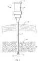
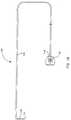
- the ablation assemblygenerally designated 10 (illustrated in Fig. 3), includes a relatively thin, elongated probe 12 (illustrated in Fig. 1), which works in combination with an ablation tool 24 (illustrated in Fig. 2).
- the probe 12has a proximal access end 14 and an opposite distal penetration end 16 adapted to penetrate an organ 18 within a body cavity 20.
- the probe 12also has a longitudinally extending lumen 22 that is sized suitably for receiving the ablation tool 24 therethrough.
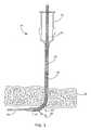
- the ablation tool 24includes a transmission line 28 that carries an antenna device 30 at its distal end.
- the antenna device 30is designed to generate an electromagnetic field sufficiently strong to cause tissue ablation.
- a proximal end 42 of the transmission line 28is coupled to an energy source (not shown).
- the antenna device 30 and the transmission line 28are sized such that they are slidable through the lumen 22 while the elongated probe 12 is positioned in a wall 35 of the organ 18.
- the ablation tool 24may be advanced within the probe 12 until the antenna device 30 is moved into a cavity within the organ 18 at a position beyond the penetration end 16 of the probe 12.
- the ablation tool 24is configured so that when it is extended beyond the penetration end 16 of the probe 12, the antenna 30 lies at an angle 38 relative to the longitudinal axis 40 of the probe 12 (the axis taken from the proximal end 14 of the probe).
- the angle 38is arranged such that when the antenna device 30 is deployed into the organ cavity, the antenna device 30 assumes a predetermined angular position that matches the shape and/or angular position of the wall to be ablated.
- a predetermined angular positionthat matches the shape and/or angular position of the wall to be ablated.
- an angular position that places the antenna device substantially parallel to the cavity wallmay be used.
- an ablation assemblywhich utilizes a thin, elongated probe as a deployment mechanism to position an antenna device within the organ targeted for ablation.
- the antenna device and the transmission lineare inserted through the passage of the probe as a unit until the antenna device is positioned inside the cavity of the organ.
- an electromagnetic fieldis emitted from the antenna device that is sufficiently strong to cause tissue ablation.
- This arrangementis especially beneficial when the areas targeted for ablation have obstructions along the outer wall of the organ.
- the ablation assemblymay be used to bypass and navigate around layers of fat or veins that surround the epicardial surface (e.g., outer wall) of the heart.
- the angular component of the ablation assemblyallows precise positioning and placement of the antenna device at specific locations within the cavity of a bodily organ. As a result, the ablative energy can be accurately transmitted towards the tissue targeted for ablation.
- the elongated probe 12includes a rigid needle 43 having an elongated needle shaft 44 adapted to pierce through the organ 18 at its distal penetration end 16.
- the distal penetration end 16may take the form of a conventional beveled tipped needle or a beveled point chamfered needle both of which form a sharp cutting edge.
- the lumen 22extends longitudinally through the needle shaft 44, and includes a proximal access opening 46 and an opposite distal penetration opening 47 at the distal penetration end 16 thereof.
- a handle 50is disposed at the proximal end of the needle shaft 44 to help facilitate the insertion and extraction of the antenna device 30 into and out of the proximal access opening 46 of the lumen 22.
- the needle shaft 44is a thin walled rigid tube having an outer diameter of about less than about 3 mm and an inner diameter of about less than 1.5 mm.
- a wall thickness in the range of between about 0.003 inches to about 0.007 inches, and a lumen diameter (inner diameter) in the range of about 0.040 inch to about 0.060 inchmay be used.
- the wall thicknessis about 0.005 inches and the lumen diameter is about 0.050 inches. This relatively small diameter size is particularly suitable for use in highly vascularized organs, such as the heart, so as to minimize the puncture diameter and, thus, potential bleeding.
- the present inventionmay be utilized to ablate the tissues of other organs, and more particularly, the interior walls of other organs as well.
- the needle shaftmay be formed from any suitable material that is rigid and bio-compatible.
- stainless steelmay be used.
- the sizesare not a limitation, and that the sizes may vary according to specific needs of each device.
- the probeis first positioned through the skin or a body cavity, and then into the targeted organ or tissues.
- the wall of the penetrated organ surrounding the needle shaftmay be employed to vertically and laterally position (and support) the probe during tissue ablation.
- the antenna device 30may be advanced into the organ cavity.
- the probe 12 and the ablation tool 24are formed as an integral unit, wherein the antenna device 30 is moved into position by advancing the ablation tool 24 through the probe from a first predetermined position to a second predetermined position.
- a handlewhich is mechanically coupled to the ablation tool 24, may be used to control the sliding movement of the antenna tool 24 through the probe 12.
- the first predetermined positionis configured to place the antenna device 30 in an un-advanced position (as shown in Fig. 3A) and the second predetermined position is configured to place the antenna device 30 in a deployed position (as shown in Fig. 3B).
- the probe 12 and the ablation tool 24are separate elements and therefore the ablation tool 24 is inserted into the probe 12 after the probe 12 has been positioned in the targeted area of the organ 18.
- the antenna device 30can be advanced from the un-advanced position (as shown in Fig. 3A) to the deployed position (as shown in Fig. 3B).
- the ablation tool 24is moved through the handle 50 and through the lumen 22.
- the antenna device 30 and the associated transmission line 28are advanced longitudinally through the lumen 22 of the needle shaft 44 to the distal penetration end 16 thereof.
- the antenna device 30may be manipulated to extend through the penetration opening 47 of the insert passage 22 and into the cavity of the organ 18.
- Such advancementallows the antenna device 30 to assume a predetermined position having an angle 38 relative to the longitudinal axis 40 of the probe 12.
- the predetermined positionis in a direction towards the inner wall of the organ 18, and substantially parallel to the tissue targeted for ablation thereof.
- the antenna deviceis arranged to move into the angled position during advancement of the antenna tool through the probe.
- the antenna deviceis arranged to move into the angled position after advancement of the antenna tool through the probe. Deployment techniques will be discussed in greater detail below.
- the probe 12is perpendicularly penetrating the organ 18, and the antenna device 30 is positioned about 90 degrees from the longitudinal axis 40 of the probe 12. It is contemplated, however, that this position is not always possible because some organs are particularly difficult to access, and therefore the probe 12 may be inserted into the wall of the organ 18 at different angles. Accordingly, the present invention may be configured to provide a range of angled positions to match the shape and/or angular position of the wall to be ablated. By way of example, an antenna device position having an angle in the range of between about 45 degrees to about 135 degrees may be used. To illustrate this, Fig.
- FIG. 4Ashows the antenna device 30 in an acute angular position having an angle 38 of about 60 degrees relative to the longitudinal axis 40
- Fig. 4Bshows the antenna device 30 in an obtuse angular position having an angle 38 of about 120 degrees relative to the longitudinal axis 40.
- the ablation assemblymay include a biasing member that is specifically formed and shaped for urging the antenna device to a predetermined bent position. That is, the biasing member has a predetermined shape that corresponds to the angled position of the antenna device. As soon as the antenna device is advanced into the organ cavity the biasing member moves to assume its predetermined shape and thus the antenna device moves to the predetermined bent position.
- the biasing membergenerally consists of one or more pre-shaped elastic or spring like strips or rods that extend through the ablation arrangement in the area of the antenna device. The strips or rods may be arranged to have a circular, rectangular, or other cross section shape.
- stainless steels, plastics and shape memory metalsmay be used.
- the spring like materialis a shape memory metal such as NiTi ( Nitinol).
- Nitinolis a super elastic material that typically exhibits superb flexibility and unusually precise directional preference when bending. Accordingly, when the antenna device is positioned within the cavity of an organ, the nitinol strip enables the antenna device to conform to the inner wall of the organ. Similarly, when the antenna device is withdrawn from the organ, the Nitinol strip facilitates straightening to allow removal through the probe.
- the assemblymay include a steering system for bending the antenna device to a predetermined bent position.
- the steering systemgenerally includes one or more wires that extend through the ablation arrangement.
- the wiresare used to pull the antenna device from an unbent position to a bent position causing controlled, predetermined bending at the antenna device.
- the pull wiresare generally fastened to anchors, which are disposed (attached to) at the proximal end of the antenna device.
- a steering element, located on the handle 50may be used to pull on the wires to facilitate the bending.
- the actual position of the handlemay vary according to the specific needs of each ablation assembly. Steering systems are well known in the art and for the sake of brevity will not be discussed in greater detail.
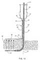
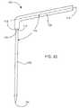
- the needle shaft of the probecan be pre-bent or curved to direct the antenna device to its advanced position.
- the needle shaft 44 of the probe 12includes a curved section 55 which redirects the position of the antenna device 30 in a manner skewed from the axis 40 of the proximal end 14 of the probe 12.
- the antenna device 30is urged toward the distal penetration opening 47 and into the cavity of organ 18 at an angle 38 relative to axis 40.
- the probeis shown as having a substantially right angle, it should be noted that the angle of the curved portion may vary according to the specific needs of each ablation assembly.
- the angle 38may also be configured to be acute or obtuse (such as in Fig. 4A & 4B) relative to the longitudinal axis 40.
- the ablation tool 24is illustrated having an elongated flexible transmission line 28 and an antenna device 30 coupled to the distal end of the transmission line 28.
- the transmission line 28is adapted for insertion into the probe 12 and is arranged for actuating and/or powering the antenna device 30.
- a coaxial transmission lineis typically used, and therefore, the transmission line 28 includes an inner conductor 31, an outer conductor 32, and a dielectric material 33 disposed between the inner and outer conductors 31, 32.
- an electrical connector 42adapted to electrically couple the transmission line 28, and therefore the antenna device 30, to the energy source (not shown).
- the transmission line 28may also include a flexible outer tubing (not shown) to add rigidity and to provide protection to the outer conductor 32.
- the flexible outer tubingmay be made of any suitable material such as medical grade polyolefins, fluoropolymers, or polyvinylidene fluoride.
- the antenna device 30,which is also adapted for insertion into the probe 12, generally includes an antenna wire 36 having a proximal end that is coupled directly or indirectly to the inner conductor 31 of the transmission line 28.
- a direct connection between the antenna wire 36 and the inner conductor 31may be made in any suitable manner such as soldering, brazing, ultrasonic or laser welding or adhesive bonding.
- the antenna device 30can be integrally formed from the transmission line 28 itself. This is typically more difficult from a manufacturing standpoint but has the advantage of forming a more rugged connection between the antenna device and the transmission line.
- This designis generally formed by removing the outer conductor 32 along a portion of the coaxial transmission line 28. This exposed portion of the dielectric material medium 33 and the inner conductor 31 embedded therein define the antenna device 30 which enables the electromagnetic field to be radiated substantially radially perpendicular to the inner conductor 31.
- the electrical impedance between the antenna device 30 and the transmission line 28are substantially the same. As a result, the reflected power caused by the low impedance mismatch is also substantially small which optimizes the energy coupling between the antenna and the targeted tissues.
- the antenna wire 36is formed from a conductive material.
- spring steel, beryllium copper, or silver plated coppermay be used.
- the diameter of the antenna wire 36may vary to some extent based on the particular application of the ablation assembly and the type of material chosen.
- wire diametersbetween about 0.005 inches to about 0.020 inches work well. In the illustrated embodiment, the diameter of the antenna is about 0.013 inches.
- the antenna wire 36can be formed from a shape memory metal such as NiTi ( Nitinol).
- Nitinolis a super elastic material that typically exhibits superb flexibility and unusually precise directional preference when bending. Accordingly, when the antenna device 30 is positioned within the cavity of an organ, the antenna wire 36 enables the antenna device 30 to conform to the inner wall of the organ. Similarly, when the antenna device 30 is withdrawn from the organ, the antenna wire 36 facilitates straightening to allow removal through the probe 12. It should be noted, however, that the electrical conductivity of the Nitinol is not very good, and as a result, Nitinol can heat significantly when power (e.g., microwave) is applied.
- powere.g., microwave
- a layer of good conducting materialis disposed over the Nitinol.
- silver plating or depositionmay be used.
- the thickness of the good conducting materialcan vary between about 0.00008 to about 0.001 inches, depending on the conductivity of the selected material.
- the length of the ablative energy generated by the ablation instrumentwill be roughly consistent with the length of the antenna device 30.
- ablation devices having specified ablation characteristicscan be fabricated by building ablation devices with different length antennas.
- an antenna lengthbetween about 20 mm and about 50 mm and more particularly about 30 mm may be used.
- the probemay be used to introduce a measuring tool that is arranged to measure the ablative lesion distance needed for a particular procedure.
- the length of the antenna devicecan be selected.
- the toolmay be used to measure the distance between the mitral valve and the pulmonary veins.
- the antenna wire 36is a monopole formed by a longitudinal wire that extends distally from the inner conductor 31.
- a wide variety of other antenna geometriesmay be used as well.
- nonuniform cross-section monopole, helical coils, flat printed circuit antennas and the likealso work well.
- longitudinally extending antennasare not a requirement and that other shapes and configurations may be used.
- the antennamay be configured to conform to the shape of the tissue to be ablated or to a shape of a predetermined ablative pattern for creating shaped lesions.
- the antenna wire 36is generally encapsulated by an antenna enclosure 37.
- the antenna enclosure 37is typically used to obtain a smooth radiation pattern along the antenna device 30, and to remove the high electromagnetic field concentration present when an exposed part of the antenna wire is in direct contact with the tissue to be ablated.
- a high field concentrationcan create a high surface temperature on the tissue to ablate which is not desirable, especially for cardiac applications.
- the antenna enclosure 37may be made of any suitable dielectric material with low water absorption and low dielectric loss tangent such as Teflon or polyethylene. As will be described in greater detail below, in some implementations, it may be desirable to adjust the thickness of the antenna enclosure 37 in order to provide better impedance matching between the antenna device 30 and the tissue targeted for ablation.
- exposing the antenna wireis not typically done because of the high field concentration, it should be noted that the dielectric material forming the antenna enclosure 37 can be removed to form an exposed metallic antenna.
- the outer conductor 32is arranged to have a distal portion 39 that is exposed, beyond the penetration end 16 of the probe 12, when the antenna device 30 is in its advanced position. While not wishing to be bound by theory it is generally believed that the radiated field tends to be more confined along the antenna device 30 when the distal end of the outer conductor 32 is extended in the organ cavity and exposed to the surrounding medium. By way of example, an exposed outer conductor having a length of about 1 mm to about 2 mm works well. Although the outer conductor is shown and described as being exposed it should be understood that this is not a limitation and that the ablation arrangement can be made with or without an exposed outer conductor.
- the antenna device and the outer conductorare covered by a layer of dielectric.
- This layer of dielectrichelps to remove the high concentration of electromagnetic field generated by the uncovered distal portion of the outer conductor.
- This configurationis better suited for cardiac applications because the high field concentration can potentially generate coagulum or carbonization that can trigger an embolic event.
- the ablation tool 24includes a protective sheath 45 that surrounds the outer periphery of the antenna device 30 and a portion of the outer conductor 32 of the transmission line 28. More specifically, the protective sheath 45 is arranged to cover at least a portion of the exposed distal portion 39 of the outer conductor 32 and the antenna enclosure 37. As shown, the protective sheath may also cover the distal end of the antenna enclosure 37.
- the protective sheathmay be formed from any suitable dielectric material such as Teflon (PTFE), FEP, Silicon and the like.
- the ablation arrangementis arranged to transmit electromagnetic energy in the microwave frequency range.
- the optimal frequenciesare generally in the neighborhood of the optimal frequency for heating water.
- frequencies in the range of approximately 800 MHz to 6 GHzwork well.
- the frequencies that are approved by the U.S. FCC (Federal Communication Commission) for experimental clinical workare 915 MHz and 2.45 GHz. Therefore, a power supply having the capacity to generate microwave energy at frequencies in the neighborhood of 2.45 GHz may be chosen.
- the power supplygenerally includes a microwave generator, which may take any conventional form. At the time of this writing, solid state microwave generators in the 1-3 GHz range are expensive.
- the transmission line 28is therefore provided by a conventional fifty ohm coaxial design suitable for the transmission of microwave energy at frequencies in the range of about 400 to about 6000 megahertz.
- the coaxial transmission line 28includes an inner conductor 31 and a concentric outer conductor 32 separated by a dielectric material medium 33.
- the inner conductor 31is formed from a solid metallic material core having good electrical conductivity.
- the dielectric medium 33is formed from a semi-rigid dielectric material having a low loss tangent.
- the outer conductor 32is formed from a braided sleeve of metallic wires that provide shielding and good flexibility thereof.
- the size of the inner conductor 31 and the outer conductor 32, as well as the size, shape and material of the dielectric material mediummust be carefully selected.
- Each of these variables, together with other factors related to the antenna device,may be used to adjust the impedance and energy transmission characteristics of the antenna device.
- Such preferable dielectric materialsinclude air expended TEFLONTM, while the inner and outer conductors are composed of silver or copper.
- the impedance of the transmission linemay be determined by the equation: where "b" is the diameter of the dielectric material medium, "a” is the diameter of the inner conductor and ⁇ r is the dielectric constant of the dielectric material medium 33.
- a characteristic impedance other than fifty ohmscan also be used to design the microwave ablation system. Also, in order to obtain good mechanical characteristics of the coaxial cable assembly, it is important to consider the hardness or malleability of the selected material.
- the antenna deviceAs it was explained earlier, it is also important to match the impedance of the antenna with the impedance of the transmission line. As is well known to those skilled in the art, if the impedance is not matched to the transmission line, the microwave power is reflected back to the generator and the overall radiation efficiency tends to be well below the optimal performance.
- tuninge.g., improving or increasing the radiation efficiency
- an impedance matching deviceis provided to facilitate impedance matching between the antenna device and the transmission line.
- the impedance matching deviceis generally disposed proximate the junction between the antenna and the transmission line.
- the impedance matching deviceis configured to place the antenna structure in resonance to minimize the reflected power, and thus increase the radiation efficiency of the antenna structure.
- the impedance matching deviceis determined by using a Smith Abacus Model.
- the impedance matching devicemay be determined by measuring the impedance of the antenna with a network analyzer, analyzing the measured value with a Smith Abacus Chart, and selecting the appropriate matching device.
- the impedance matching devicemay be any combination of serial or parallel capacitor, resistor, inductor, stub tuner or stub transmission line.
- An example of the Smith Abacus Modelis described in Reference: David K. Cheng, “Field and Wave Electromagnetics,” second edition, Addison-Wesley Publishing, 1989, which is incorporated herein by reference.
- the antenna device 30includes a tuning stub 63 for improving the radiation efficiency of the antenna device 30.
- the tuning stub 63is a circumferentially segmented section that extends distally from the distal end 53 of the outer conductor 32.
- the tuning stub 63is integrally formed from the outer conductor 32 and in other embodiments, the tuning stub 63 is coupled to the outer conductor 32.
- the tuning stub 63is generally positioned on one side of the antenna device 30, and more particularly to the side which is closest to the tissue targeted for ablation (e.g., angular component side).
- the tuning stub 63is also arranged to partially cover or surround the antenna enclosure 37.
- the tuning stub 63may cover between about 25 % to about 50 % of the perimeter of the antenna enclosure 37. Furthermore, the length L of the tuning stub 63 may be adjusted to further improve the radiation efficiency of the antenna device 30. For example, by increasing the length L, less power is reflected at the entrance of the antenna device 30 and the radiation efficiency of the system is increased. The radiation efficiency of the antenna device 30 is maximized when the resonance frequency is the same as the electromagnetic signal produced by the generator (2.45 GHz for example).
- the antenna device 30includes a pair of director rods 65 for improving the radiation efficiency of the antenna device 30.
- the director rods 65are generally positioned on one side of the antenna device 30, and more particularly to the side which is closest to the tissue targeted for ablation (e.g., angular component side).
- the director rods 65are disposed on the periphery of the antenna enclosure 37 and may be positioned anywhere along the length of the antenna device 30.
- one of the director rods 65may be positioned proximate the distal end of the antenna device 30, while the other director rod 65 may be positioned proximate the proximal end of the antenna device 30.
- the position of the director rodsmay be adjusted to further improve the radiation efficiency of the antenna device 30.
- the director rodsare generally formed from a suitable metallic material such as silver, and may also be formed from any material, which is silver-plated, for example, silver plated stainless steel or silver plated copper. Furthermore, the size (length and width) of the director rods 65 may be adjusted to further improve the radiation efficiency of the antenna device 30. It should be appreciated that a pair of rods is not a limitation and that a single rod or more than a pair rods may be used.
- microwave energydoes not have to be in contact with targeted tissue in order to ablate the tissue.
- This conceptis especially valid for cardiac ablation.
- the radiated electromagnetic fielddoes not see an impedance change between the blood and the myocardium (since the complex permittivity of these two media are similar).
- the circulating blood between the antenna device and the tissue to be ablatedhelps to cool down the tissue surface.
- the techniqueis potentially safer since it is less prone to create coagulation and/or carbonization.
- a non-contact distance of about 1 to about 2 mmmay be used.
- the antenna device, and more particularly the antenna enclosuremay be positioned in direct contact with the tissue to ablate.
- the antenna devicewhen the antenna device is not directly touching the tissue to be ablated, the surrounding cavity is filled with a liquid before ablating the tissue.
- a better ablationmay be achieved that is potentially safer since it is less prone to create coagulation and/or carbonization.
- liquidssuch as isotonic saline solution or distilled water may be used.
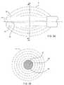
- the antenna device 30is adapted to deliver electromagnetic energy (e.g., microwave) in directions extending substantially radially perpendicularly from the longitudinal axis 51 of the antenna wire 36 and through the antenna enclosure 37. That is, the antenna device 30 generally produces a radial isotropic radiation pattern 41 wherein the generated energy is homogeneously distributed around its volume.
- the radiation pattern 41 generated by the antenna device 30generally has an ellipsoidal shape along the length of the antenna device 30 (as shown in Fig. 9A), and a circular shape around its width (as shown in Fig. 9B).
- the antenna devicemay be arranged to provide other ablative patterns.
- the antenna devicemay be arranged to form a cylindrical ablative pattern that is evenly distributed along the length of the antenna, an ablative pattern that is directed to one side of the antenna device, an ablative pattern that supplies greater or lesser energy at the distal end of the antenna device and/or the like.
- the thickness of the antenna enclosureis varied along the longitudinal length of the antenna device in order to adjust the radiation pattern of the electromagnetic field to produce a better temperature profile during ablation. That is, the antenna enclosure thickness can be used to improve field characteristics (e.g., shape) of the electromagnetic field. As a general rule, a thicker enclosure tends to cause a decrease in radiation efficiency, and conversely, a thinner enclosure tends to cause an increase in radiation efficiency. Thus, by varying the thickness along the length of the antenna, the amount of energy being delivered to the tissue can be altered. As such, the thickness can be varied to compensate for differences found in the tissue being ablated.
- field characteristicse.g., shape
- the antenna devicecan be configured to deliver a greater amount of energy to a specific area and in other cases the antenna device can be configured to deliver energy more uniformly along the length of the antenna. For instance, if the delivered energy at the proximal end of the antenna is greater than the energy at the distal end, then the thickness of the dielectric material can be increased at the proximal end to reduce the radiation efficiency and therefore create a more uniform radiation pattern along the antenna. Consequently, a more uniform heating distribution can be produced in the tissue to ablate.
- the antenna device 30includes a tuning sleeve 77 for altering the radiation pattern of the antenna device 30.
- the tuning sleeve 77is formed from a suitable dielectric material and is arranged to increase the thickness of the antenna enclosure 37.
- the tuning sleevemay be formed from the same material used to form the antenna enclosure.
- the tuning sleeve 77is integrally formed from the antenna enclosure 37 and in other embodiments, the tuning sleeve 77 is coupled to the antenna enclosure 37.
- the tuning sleeve 77is disposed around the periphery of the antenna enclosure 37 and may be positioned anywhere along the length of the antenna device 30.
- the tuning sleevemay be positioned at the proximal end or distal end of the antenna device, as well as anywhere in between the proximal and distal ends of the antenna device.
- the position and length of the tuning sleeve 77may also be adjusted to alter the radiation pattern of the antenna device.
- the tuning sleeveis shown as surrounding the antenna enclosure, it should be noted that it may also be circumferentially segmented.
- a single sleeveis not a limitation and that a plurality of sleeves may be used.
- the tip of the antenna wirecan be exposed to further alter the field characteristics.
- An exposed tipgenerally produces "tip firing", which can be used to produce more energy at the distal end of the antenna.
- the stub tunermay be used to alter the radiation pattern of the antenna device.
- the director rodsmay be used to alter the radiation pattern of the antenna device.
- the antenna device 30includes a reflector 71, which is arranged to direct a majority of an electromagnetic field to one side of the antenna wire 36 and thus to one side of the antenna device 30.
- the reflector 71is positioned laterally to a first side of the antenna wire 36 and is configured to redirect a portion of the electromagnetic field that is transmitted towards the reflector 71 to a second side of the antenna wire 36 opposite the reflector 71.
- a resultant electromagnetic field including a portion of the generated and a portion of the redirected electromagnetic fieldis directed in a desired direction away from the second side of the antenna wire 36.
- the desired directionis preferably in a direction towards the tissue to be ablated and thus the reflector is disposed on the side of the antenna device opposite the direction set for ablation. Furthermore, the reflector is disposed substantially parallel to the antenna to provide better control of the electromagnetic field during ablation.
- the reflectoris generally coupled to the outer conductor of the transmission line. Connecting the reflector to the outer conductor serves to better define the electromagnetic field generated during use. That is, the radiated field is better confined along the antenna, to one side, when the reflector is electrically connected to the outer conductor of the transmission line.
- the connection between the reflector and the outer conductormay be made in any suitable manner such as soldering, brazing, ultrasonic welding or adhesive bonding.
- the reflectorcan be formed from the outer conductor of the transmission line itself. This is typically more difficult from a manufacturing standpoint but has the advantage of forming a more rugged connection between the reflector and the outer conductor.
- metallization techniquesare used to apply a reflective surface onto the antenna enclosure.
- the reflector 71is typically composed of a conductive, metallic mesh or foil.
- a conductive, metallic mesh or foilis silver plated copper.
- Another suitable arrangementmay be a stainless steel mesh or foil that has a layer of silver formed on its inner peripheral surface.
- these materialsare not a limitation.
- the actual thickness of the reflectormay vary according to the specific material chosen.
- the reflector 71is configured to have an arcuate or meniscus shape (e.g., crescent), with an arc angle that opens towards the antenna wire 36. Flaring the reflector 71 towards the antenna wire 36 serves to better define the electromagnetic field generated during use.
- the arc angleis typically configured between about 90° to about 180°. By way of example, an arc angle of about 120° works well. Additionally, it has been found that if the arc angle 90 is greater than 180° the radiation efficiency of the antenna arrangement decreases significantly.
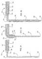
- a metallic needle shaft 44is used as an electrical continuation of the outer conductor 32.
- the outer conductor 32includes a contact member 60 that is disposed at the distal end of the outer conductor 32.
- the contact member 60is arranged to electrically couple the outer conductor 32 to the needle shaft 44 when the ablation tool is moved through the probe 12, and more particularly when the ablation tool reaches its deployed position (as shown in Fig. 12B).
- the distal portions of the transmission line 28are appropriately sized such that only the dielectric material medium 33 and the inner conductor 31 are slideably received in the lumen 22 of the metallic needle shaft 44.
- the contact member 60is adapted to contact the distal end 46 of the needle shaft 44.
- the metallic needle shaft 44can act as an extension of the outer conductor 32 of the transmission line 28.
- portions of the ablation tool 24 that are disposed proximally from the contact member 60are designated with an A
- portions of the ablation tool 24 that are disposed distally from the contact member 60are designated with a B.
- the assemblycomprising the inner conductor 31B, the dielectric material 33B and the metallic needle shaft 44 creates a distal coaxial cable 28B.
- the needle shaft 44conductively functions as a shield for the transmission line 28 from the access opening 46 to the distal penetration opening 47 of the probe 12.
- this shielding effectcommences when the outer conductor 32 of the transmission line 28 and the needle shaft 44 of the probe 12 are in conductive communication with one another.
- the outer conductor 32must therefore be in conductive communication with the metallic needle shaft 44 at least when the antenna device 30 is radiating electromagnetic energy.
- the contact member 60is adapted to electrically contact the proximal part 46 of the needle shaft 44 when the antenna device 30 is fully extended through the needle shaft 44 and into the targeted organ 18.
- the contact member 60not only operates as an electrical connector between the outer conductor 32 and the needle shaft 44 but also as a stop device that limits the amount of penetration into the organ.
- the size of the contact member 60is merely larger than that of the access opening.
- the dimensions of the distal coaxial cable elementsare generally selected to match the impedance of the proximal transmission line.
- the cross sectional dimensions of 28B, 31B and 33Bmay be different from 28A, 31A and 33A.
- the length of the antenna device 30is generally defined from the center of the distal penetration opening 47 to the distal end of the antenna wire 36.
- the matching of the antennais performed by adjusting its length so that the radiation efficiency is adequate when the antenna is used in the tissue or in the organ cavity.
- the radiation efficiencyis generally adequate when the return loss of the antenna is in the range of -10 dB to -13 dB at 2.45 GHz.
- Instruments having specified ablation characteristicscan be designed by varying the antenna length.
- the antenna devicemay have an antenna wire diameter of about 0.013 inch, a dielectric material medium diameter of about 0.050 inch and a length in the range of approximately 20 mm to 30 mm.
- the distal coaxial cablecan also be used as a serial stub tuner to match the impedance of the antenna device 30 and the transmission line 28.
- This arrangementis advantageous since, while maintaining the electrical continuation and the impedance match between the generator and the antenna, the diameters of the inner conductor 31 and the dielectric material medium 33 can be maximized relative the insert passage 22. The larger diameters, consequently, facilitate axial penetration into the organ due to the increased lateral and axial rigidity without compromising the impedance matching of about fifty (50) ohms.
- the ablation assembly 10includes a clamping portion 79 for positioning the antenna device 30 proximate the wall 82 of the organ 18.
- the clamping portion 79 and the antenna device 30are arranged to facilitate linear positioning of the antenna device 30.
- the clamping portion 79generally includes a clamping finger 81 and a bar slide 84 that is slidably coupled to the needle shaft 44 and is configured to move relative to the probe 12.
- the bar slide 84is configured to slide within at least one guide track 86 that is structurally attached to the needle shaft 44.
- the clamping portion 79is also arranged to be substantially aligned (in the same plane) with the antenna device 30 when the antenna device 30 is in its angular position.
- the clamping portion 79is moved in a direction towards the organ 18 to pinch the organ wall between the antenna 30 and the clamping finger 81. That is, the clamping finger 81 is moved to a position that contacts the outer wall 88 of the organ 18, wherein after contact and upon further finger movement the antenna device 30 is forced to move in a direction towards the probe 12.
- the antenna device 30 and clamping finger 81exert opposite forces on opposite sides of the organ wall.
- the finger and the antenna devicecan be used to sandwich the myocardium of the heart wherein the finger is applying a force to the epicardial surface and the antenna device is applying an opposing force to the endocardium. This particular approach tends to create a more uniform ablating surface, which as result, produces a better linear lesion.
- the clamping fingeris generally configured to be parallel to the angular position of the deployed antenna device.
- the fingermay be configured to have an angle of about 60 degrees relative to the axis of the probe. In this manner, the antenna device and clamping finger can pinch the organ wall evenly.
- the clamping fingercan be shaped to conform to the shape of the outer wall.
- the clamping fingergenerally has a length that is substantially equivalent to the length of the antenna device. However, it should be noted that the length may vary according to the specific design of each ablation assembly.
- the slide barmay be connected to a handle for physically actuating the linear movement, a knob or jack for mechanically actuating the linear movement, or an air supply for powering the linear movement.
- a locking mechanismmay also be used to lock the engagement between the clamp finger and the antenna device so that the antenna device does not move from the target area during ablation.
- a sealmay be used between the clamp finger and the outer wall of the organ to seal the puncture site.
- a suction devicemay be disposed on the clamping finger to anchor and temporarily position the clamping finger to the outer organ wall.
- a balloon that is attached to the probemay be used to pinch the organ wall between the inflated balloon and the angularly positioned antenna device.
- the ablation assembly 10includes a ground plane 89 for coupling electromagnetic energy 90 through the organ wall 35.
- the ground plane 89generally provides a metallic surface that attracts the electric field generated by the antenna device 30 and therefore a more intense electromagnetic field 90 is produced between the antenna device 30 and the ground plane 89. Accordingly, the electromagnetic field 90 emitted by the antenna device 30 is more constrained in the tissue 35 between the antenna device 30 and the ground plane 89, which as a result helps to create the ablation.
- inserting the tissue to ablate between the ground plane 89 and the antenna 30has several potential advantages over conventional antenna structures. For example, by forming a concentrated electromagnetic field, deeper penetration of biological tissues may be obtained during ablation and the biological tissue targeted for ablation may be ablated without heating as much of the surrounding tissues and/or blood. Further, since the radiated power is not lost in the blood, less power is generally required from the power source, and less power is generally lost in the transmission line, which tend to decrease its temperature. Additionally, this arrangement may be used to form lesions that are more precise.
- the ground plane 89is electrically coupled to the outer conductor 32 of the transmission line 28.
- the ground plane 89is generally disposed on the needle shaft 44 of the probe 12 at a predetermined distance Q away from the deployed antenna device 30 (as shown in Fig. 14B).
- the predetermined distance Qis arranged to place the ground plane 89 in close proximity to the antenna device 30, and outside the outer wall of the organ 18 when the needle shaft 44 is position inside the organ wall 35.
- a distance between about 1 mm and about 15 mmmay be used.
- the ground plane 89is generally configured to be parallel to the angular position of the antenna device 30.
- the ground planemay be configured to have an angle of about 60 degrees relative to the axis of the transmission line. In this manner, the antenna and the ground plane can couple energy more evenly.
- the ground planecan be shaped to conform to the shape of the outer wall.
- the ground planegenerally has a length that is substantially equivalent to the length of the antenna device 30.
- a ground plane length between about 20 mm and about 50 mmworks well. It should be noted, however, that the length may vary according to the specific needs of each ablation assembly.
- the ground planeis also arranged to be substantially aligned (in the same plane) with the angular component of the antenna device 30.
- the ground plane 89may be formed from a wire, strip or rod, and may be arranged to have a circular, rectangular, or other cross section shape. Furthermore, the ground plane 89 is formed from a suitable conductive material such as stainless steel or silver. The dimensions of the ground plane 89 may vary to some extent based on the particular application of the ablation assembly and the type of material chosen. Additionally, the ground plane may be printed on or enclosed inside of a flexible dielectric substrate (such as Teflon or polymide). Furthermore, the connection between the ground plane 89 and the outer conductor 32 may be made in any suitable manner such as soldering, brazing, ultrasonic welding or adhesive bonding.
- the ground plane 89can be configured in a variety of ways.
- the ground planemay be rigidly or structurally coupled to the needle shaft of the probe.
- the ground planemay be pivoted or slidably coupled to the needle shaft of the probe.
- the clamping fingeras described above in Fig. 13, can be arranged to be a ground plane for the antenna.
- the ground planemay be flexible in order to follow the natural curvature of the organ.
- the ground planemay be biased to contact the tissue.
- the ground planemay be configured to act as a stop device that limits the amount of probe penetration into the organ.
- the ground planemay be properly positioned across from the antenna device with a ground plane positioner.
- the ground plane positionergenerally includes tubular member having passage therein.
- the ground planeis advanced longitudinally through the passage of the tubular member to the distal opening of the passage.
- the ground planemay be manipulated to extend through distal opening of the passage and to the outer wall of the organ.
- Such advancementpreferably allows the ground plane to assume a predetermined position that is substantially aligned with the deployed antenna device such that the organ wall is disposed between the ground plane and the antenna device.
- the assemblymay include a biasing member that is specifically formed and shaped for urging the ground plane to a predetermined bent position.
- the assemblymay include a steering system for bending the ground plane to a predetermined bent position.
- the needle shaft of the tubular membercan be prebent or curved to direct the ground plane to its advanced position.
- the ablation assembly 10includes a positioner 91 having a tubular member 92 and a passage 94 therein.
- the ground plane 96is electrically coupled to the outer conductor 32 of the transmission line 28.
- the tubular memberincludes a curved section 95 which redirects the position of the ground plane 96 in a manner skewed from the axis 40 of the proximal end 14 of the probe 12.
- the ground plane 96is urged out of the distal opening 97 and to an outer wall position that is substantially aligned with the angled antenna device 30.
- the ground plane 96may be fixed to the transmission line 28 such that when the antenna device 30 is deployed so is the ground plane 96.
- Fig. 16an alternative embodiment to the present invention is illustrated wherein the ablation assembly 10 is inserted through an access device 70, which is positioned in the body cavity 20.
- the access device 70is generally disposed inside a small incision that is made in the body cavity 20.
- the access deviceincludes a passage 72 that is appropriately sized for receiving the ablation assembly 10 such that the needle shaft 44 of probe 12 can be introduced into the body cavity 20.
- the passage 72allows access to the targeted organ 18. Access devices are well known to those skilled in the art and therefore they will not be described in detail herein.
- the described ablation assembly 10is used for ablating cardiac tissues, in accordance with one embodiment of the present invention.
- the ablation assembly 10is especially beneficial in navigating around certain regions of the heart 200.
- the ablation assembly 10may be used to bypass the layers of fat 202 or veins 204 that surround the epicardial surface 206 (e.g., outer wall) of the heart 200.
- the vein 204may be the coronary sinus, which is located just superior to the junction between the left atrium 240 and the left ventricle 246.
- fat 202is a good microwave absorber and a very poor thermal conductor.
- veins 204readily transfer heat through blood flow.
- the ablative energycan be supplied to the endocardium 210 rather than the obstructed epicardial surface 206 thereby effectively ablating the targeted tissue.
- the cavity 208may be the left atrium 240, the right atrium 242, the left ventricle 246 or the right ventricle 244.
- the ablation assembly 10may be used to treat a variety of heart conditions. In one embodiment, the ablation assembly is used to treat atrial fibrillation and in another embodiment the ablation assembly is used to treat atrial flutter. Several implementations associated with ablating cardiac tissues using the ablation assembly 10 will now be described.
- the ablation assembly 10is used to create lesions between any of the pulmonary veins 212 of the heart 200 in order to treat atrial fibrillation. In another implementation, the ablation assembly 10 is used to create lesions from one of the pulmonary veins 212 to the mitral valve 213 of the heart 200 in order to avoid macro-reentry circuit around the pulmonary veins in a lesion pattern used to treat atrial fibrillation. In another implementation, the ablation assembly 10 is used to create lesions from one of the pulmonary veins 212 to the left atrial appendage of the heart 200 also to avoid macro-reentry circuit around the pulmonary veins in a lesion pattern used to treat atrial fibrillation.
- the ablation assembly 10is used to create lesions between the inferior caval vein 216 to the tricuspid valve 214 of the heart 200, in order to treat typical or atypical atrial flutter. In another implementation, the ablation assembly 10 is used to create lesions along the cristae terminalis in the right atrium 242 of the heart 200 in order to treat typical or atypical atrial flutter. In another implementation, the ablation assembly 10 is used to create lesions from the cristae terminalis to the fossae ovalis in the right atrium 242 of the heart 200 in order to treat typical or atypical atrial flutter.
- the ablation assembly 10is used to create lesions on the lateral wall of the right atrium 242 from the superior 220 to the inferior vena cava 216 in order to treat atypical atrial flutter and/or atrial fibrillation.
- the methodincludes providing an ablation assembly such as any one of the ablation assemblies described herein. More particularly, the method includes providing a surgical device 10 having a probe 12 and an elongated microwave ablation arrangement 24.
- the probe 12includes a passage extending therethrough from a proximal end 14 to an opposite distal end 16 thereof.
- the distal end 16is adapted to penetrate through a muscular wall 222 (e.g., myocardium) of the heart 200.
- the elongated microwave ablation arrangement 24includes a distal antenna 30 coupled to a transmission line, which in turn is coupled to a microwave energy source at a proximal end thereof.
- the methodincludes introducing the surgical device 10 into a body cavity 230. This may be by penetration of the body 232 or through an access device 70.
- the surgical devicemay be introduced through an open chest, a posterior thoracotomy, a lateral thoracotomy (as shown in Fig. 10), or a sternotomy.
- the surgical procedurecan also use an endoscope in order to visualize the ablation device during the placement. These procedures are generally well known to those skilled in the art and for the sake of brevity will not discussed in detail.
- the methodfurther includes penetrating the muscular wall 222 of the heart 200 with the distal end 16 of the elongated probe 12 and introducing the elongated probe 12 through the muscular wall 222 of the heart 200 and into an interior chamber 208 thereof.
- the surgical tool 10can be introduced into the left atrium 240, the right atrium 242, the right ventricle 244 or the left ventricle 246.
- a purse string suturemay be placed in the heart wall proximate the area targeted for penetration so as to provide tension during penetration. Purse string sutures are well known in the art and for the sake of brevity will not be discussed in more detail.
- the methodalso includes introducing the elongated microwave ablation device 24 into the passage of the elongated probe 12 and advancing the antenna 30 past the distal end 16 of the probe 12 such that the antenna 30 is disposed inside the interior chamber 208 of the heart 200.
- the antenna 30preferably assumes a predetermined position that substantially matches the shape and/or angular position of the wall to be ablated.
- the positionmay place the antenna substantially parallel to the interior surface 210 (e.g. endocardium) of the penetrated muscular wall 222 and proximate the targeted tissue.
- Angled advancementmay be accomplished in a variety of ways, for example, with a biasing member, a steering wire or a curved probe.
- the methodincludes generating a microwave field at the antenna that is sufficiently strong to cause tissue ablation within the generated microwave field.
- the ablation assemblyincludes a needle and a transmission line having a longitudinal axis.
- the needleis adapted to be inserted into a body cavity and to penetrate an organ (or duct) within the body cavity.
- the needleis also configured for insertion into a cavity within the organ and includes an antenna for transmitting electromagnetic energy.
- the transmission lineis coupled to the antenna and configured for delivering electromagnetic energy to the antenna.
- the ablation assemblyis arranged so that when the needle is finally inserted into the organ cavity, the antenna lies at an angle relative to the longitudinal axis of the transmission line.
- the needle or the transmission lineis pre-shaped or bent at a predetermined position that is arranged to substantially match the shape and/or angular position of the wall to be ablated.
- a biasing member or steering systemin a manner similar to biasing member and steering system described above, may be used to provide angled positioning.
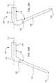
- an ablation assemblygenerally designated 100
- the ablation assembly 100further includes a transmission line 108 having a longitudinal axis 110 and a distal end 112 that is coupled to the proximal end 114 of the needle 102 for generating an electromagnetic field sufficiently strong to cause tissue ablation.
- an electrical connector 120adapted to electrically couple the antenna to an electromagnetic energy source (not shown).
- the needle 102is bent at an angle 116 relative to the longitudinal axis 110 of the transmission line 108.
- the bendis arranged to easily position the antenna parallel to the tissue to ablate by taking into consideration the angle of approach (the angle used to insert the needle through the organ).
- the ablation assembly 100utilizes the needle 102 to provide ablative energy within a cavity of the organ 106. That is, the distal penetration end 104 is used to pierce through an outer wall 122 of the organ 106 to position the needle 102 proximate and substantially parallel to an inner wall 124 of the organ 106. Once the needle 102 is positioned, ablative energy that is sufficiently strong to cause tissue ablation is emitted from the needle 102 to ablate a portion of the inner wall 124. This arrangement is especially beneficial when the areas targeted for ablation have obstructions along the outer wall of the organ. For example, the needle may be used to bypass and navigate around layers of fat or veins that surround the epicardial surface (e.g., outer wall) of the heart. Furthermore, the angled position of the needle assures that the ablative energy will be accurately transmitted in the targeted ablation region.
- the distal penetration end 104is used to pierce through an outer wall 122 of the organ 106 to position the needle 102 proximate and substantially parallel to an
- the needle 102includes an elongated antenna 130 and an antenna enclosure 132 that are adapted to pierce through organ 106 at a distal penetration end 104.
- the distal penetration end 104is in the form of a conventional beveled tipped needle or a beveled point chamfered needle which forms sharp cutting edge.
- the antenna 130is encapsulated by the antenna enclosure 132, which is generally better suited to remove the high electromagnetic field concentration that is normally obtained when the metallic part of the antenna is in direct contact with the tissue.
- a high field concentrationcan create a high surface temperature on the tissue to ablate which is not desirable, especially for cardiac applications.
- the antenna enclosure 132may be made of any suitable dielectric material (e.g., low loss tangent) with low water absorption such as medical grade epoxy, polyethylene or Teflon type products (e.g., bio compatible). As was described in great detail above, it may be desirable to adjust the thickness of the antenna enclosure in order to provide better impedance matching between the antenna and the tissue targeted for ablation. It is contemplated, however, that needle antenna enclosures having a thickness between about 0.002 inches and about 0.015 inches, and more particularly about 0.005 inches work well.
- the antenna enclosuremay not be required for all ablation assemblies.
- Figs. 22 & 24show the ablation assembly 100 with an exposed antenna 130 having no antenna enclosure.
- the antenna enclosureis configured to insulate the antenna to avoid the charring and tissue destruction effects that are commonly experienced when the ablative elements, and more particularly, the metallic parts of the antenna, are directly in contact with the body's tissue or fluid.
- the antenna 130is formed from a conductive material.
- a conductive materialBy way of example, spring steel, beryllium copper, or silver plated copper work well.
- the diameter of the antenna 130may vary to some extent based on the particular application of the ablation assembly and the type of material chosen.
- wire diametersbetween about 0.005 inch to about 0.020 inches work well. In the illustrated embodiment, the diameter of the antenna is about 0.013 inches.
- the field generated by the antennawill be roughly consistent with the length of the antenna. That is, the length of the electromagnetic field is generally constrained to the longitudinal length of the antenna. Therefore, the length of the field may be adjusted by adjusting the length of the antenna. Accordingly, ablation arrangements having specified ablation characteristics can be fabricated by building ablation arrangements with different length antennas. By way of example, antennas having a length between about 20 mm and about 50 mm, and more particularly about 30 mm work well. Furthermore, the antenna shown is a simple longitudinally extending exposed wire that extends distally from the inner conductor. However it should be appreciated that a wide variety of other antenna geometries may be used as well.
- helical coilsflat printed circuit antennas and other antenna geometries will also work well.
- longitudinally extending antennasare not a requirement and that other shapes and configurations may be used.
- the antennamay be configured to conform to the shape of the tissue to be ablated or to a shape of a predetermined ablative pattern for creating shaped lesions.
- the transmission line 108generally includes an inner conductor 134 and an outer conductor 136 separated by a dielectric material medium 138.
- An insulating sheath 140is typically disposed around the outer conductor 136.
- the outer conductor 136is generally arranged to have a portion 136A that extends from the distal end of the insulating sheath 140 so that it can be exposed.
- an exposed outer conductor having a length of about 1 mm to about 2 mmworks well.
- the outer conductoris shown and described as being exposed it should be understood that this is not a limitation and that the ablation arrangement can be made with or without an exposed outer conductor.
- the transmission line 108is provided by a conventional fifty (50) ohm coaxial design suitable for the transmission of microwave energy at frequencies in the range of about 400 to about 6000 megahertz.
- the inner conductor 134is provided by a solid metallic material core surrounded by a flexible semi-rigid dielectric material medium 138.
- the outer conductor 136includes a braided sleeve of metallic wires surrounding the inner conductor 134 to provide shielding and good flexibility thereof.
- the insulating sheathis generally flexible and may be made of any suitable material such as medical grade polyolefins, fluoropolymers, or polyvinylidene fluoride. By way of example, PEBAX resins from Autochem of Germany have been used with success.
- the proximal end 114 of the antenna 130is coupled directly or indirectly to the distal end 112 of the inner conductor 134 of the transmission line 108.
- a direct connection between the antenna 130 and the inner conductor 134may be made in any suitable manner such as soldering, brazing, ultrasonic welding or adhesive bonding.
- the antenna 130can be integrally formed from the transmission line 108 itself. This is typically more difficult from a manufacturing standpoint but has the advantage of forming a more rugged connection between the antenna and the transmission line.
- the ablation assembly 100is preferably thin having a diameter in the range of between about 1.5 mm to about 3 mm, and more preferably about 2 mm. This relatively small diameter size is particularly suitable for use in most bodily organs, such as the heart, so as to minimize the puncture diameter and, thus, potential bleeding. It will be appreciated, however, that the present invention may be used to ablate other organs or tissue as well. Additionally, the ablation assembly must be sufficiently flexible to accommodate normal operational use, yet be sufficiently rigid to prevent buckling of the line during penetrative manipulation of the needle into the targeted organ.
- the ablation assembly 100includes a bend 150 that places the needle 102 at an angle relative to the longitudinal axis 108 of the transmission line 110. As shown in Fig. 21, the bend 150 is placed along a distal portion of the transmission line. Alternatively, the bend 150 may be placed along a proximal portion of the needle as shown in Fig. 23. In either case, the bend 150 is arranged such that when the needle 102 is introduced into the organ cavity, the needle is disposed at a predetermined position that is arranged to substantially match the shape and/or angular position of the wall to be ablated. That is, the needle is bent in a direction towards the tissue targeted for ablation.
- the needlemay be configured to be bent in a direction that places the needle substantially parallel and proximate the tissue to be ablated. Furthermore, bend 150 is arranged to be sufficiently rigid to prevent buckling of the line during penetrative manipulation of the needle into the targeted organ.
- the ablation assembly 100is shown perpendicularly penetrating the organ wall 106. It is contemplated, however, that this position is not always possible because some organs are particularly difficult to access, and therefore the needle may be inserted into the wall of the organ at different angles. Accordingly, the present invention may be configured to provide a range of angled bends. By way of example, an antenna position having an angle in the range of between about 45 degrees to about 135 degrees with respect to the longitudinal axis of the transmission line works well. However, it should be noted that this is not a limitation and that other angles, as well as other bend configurations, may be used.
- the ablation assemblycan be configured to have multiple bends, curvilinear bends, rectilinear bends, three dimensional bends or have a shape that conforms to the shape of the tissue to be ablated or the ablating line desired.
- Figs. 25A & 25Bshow a variety of ablation assembly configurations.
- Fig. 25Ashows the needle 102 in an acute angular position relative to longitudinal axis 110.
- Fig. 25Bshows the needle 102 in an obtuse angular position relative to longitudinal axis 110. Again, these angular positions are important parameters for ensuring that the antenna device is properly positioned in a direction towards the tissue targeted for ablation.
- the ablation assembly 100includes a handle 160 that provides gripping surfaces for manipulating the needle 102 through the organ wall.
- the handle 160is configured for receiving surgical tools such as forceps (not shown).
- the needle 102may be positioned in the organ by holding the handle 160 with forceps and maneuvering the forceps such that the needle 102 penetrates through the organ wall. Subsequently, the forceps may be used to position the needle 102 proximate the tissue targeted for ablation.
- the handle 160is disposed on the transmission line 108 at a predetermined distance X away from the bent portion 150 of the assembly 100.
- the predetermined distance Xis arranged to place the handle 160 in close proximity to the needle 102, and outside the outer wall of the organ when the needle 102 is positioned inside the organ.
- a distance between about 1 cm and about 3 cmworks well.
- a handle formed from a polymer having a width between about 5 mm and about 10 mm, a length between about 2 mm and about 5 mm, and a height between about 5 mm and about 10 mmworks well.
- the handleis shown as being rectangular it should be noted that this is not a limitation and that the handle can be arranged with a plurality of different shapes.
- the handleis arranged to provide additional support (rigidity and strength) at the junction between the antenna and the inner conductor of the transmission line.
- the handleis arranged to enclose an impedance matching device located between the antenna and the inner conductor.
- the handlecan be arranged to be slidably coupled to the transmission line such that the handle can be used to clamp the wall of the organ between the bent needle and the handle.
- a sealmay be used between the handle and the outer wall of the organ to seal the puncture site.
- the handlemay include a balloon for biasing contact between the handle and the bent antenna.
- the ablation assembly 100includes a ground plane strip 170 for coupling electromagnetic energy through the organ wall 106.
- the ground plane 170generally provides a metallic surface that attracts the electric field generated by the antenna 130 and therefore a more intense electromagnetic field 180 is produced between the antenna 130 and the ground plane 170.
- a more efficient, controlled and concentrated electric fieldcan be used to ablate the targeted tissue.
- less powermay be required from the power source because of the more efficient use of the energy.
- the ground plane 170is electrically coupled to the outer conductor 136 of the transmission line 108.
- the ground plane 170is generally disposed on the transmission line 108 at a predetermined distance Y away from the antenna 130 of the needle 102.
- the predetermined distance Yis arranged to place the ground plane in close proximity to the needle 102, and outside the outer wall of the organ 106 when the needle 102 is positioned inside the organ 106.
- a distance between about 1 mm and about 15 mmworks well.
- the ground plane 170must be sufficiently flexible to accommodate needle maneuvering, normal operational use and storage thereof, yet be sufficiently rigid to prevent buckling or bends in the ground plane when the needle is positioned inside the organ cavity.
- the ground plane 170may be formed from a metallic foil. By way of example, silver, stainless steal or gold work well.
- the ground plane 170can also be formed from a flexible dielectric substrate with one or two metallic surface(s). By way of example, KaptonTM or TeflonTM substrates work well.
- the thickness of the ground plane 170may vary to some extent based on the particular application of the ablation assembly and the type of material chosen. By way of example, a strip thickness between about 0.005 inch to about 0.040 inch works well. In the illustrated embodiment, the thickness of the ground plane strip is about 0.010 inch.
- the connection between the ground plane 170 and the outer conductor 136may be made in any suitable manner such as soldering, brazing, ultrasonic welding or adhesive bonding.
- ground planeis shown and described as a strip it should be noted that this is not a limitation and that the ground plane may vary in form according to the specific needs of each assembly.
- a metallic wire formed from silver having a diameter between about 1 mm and about 2 mmworks well.
- a plate formed from silver having a thickness between about 0.005 inch and about 0.040 inch and a width between about 2 mm and about 5 mmworks well.
- the ground planeis generally configured to be parallel to the angular position of the needle 102.
- the ground planemay be configured to have an angle of about 60 degrees relative to the axis of the transmission line.
- the antenna and the ground planecan couple energy more evenly.
- the ground planecan be shaped to conform to the shape of the outer wall.
- the ground planegenerally has a length that is substantially equivalent to the length of the antenna 130.
- a ground plane lengthbetween about 20 mm and about 50 mm works well. It should be noted, however, that the length may vary according to the specific needs of each ablation assembly.
- the ground planeis also arranged to be substantially aligned (in the same plane) with the bent portion of the needle 102.
- the ground planeis arranged to be part of the handle.
- the electrodeis movably coupled to transmission line.
- the ground planemay be pivotly or slidably coupled to the transmission line.
- the ground planeis biased to contact the tissue.
- the methodincludes providing a surgical device 100 having a needle 102 coupled to a transmission line 108.
- the transmission line 108is arranged to have a portion with a longitudinal axis 110 and a proximal end 120 coupled to an electromagnetic energy source.
- an electromagnetic energy sourcesuch as a microwave energy source that generates energy in the microwave frequency range works well.
- the needle 102includes a distal end 104 that is adapted to penetrate through a wall of an organ 106 and an antenna 130 for generating a microwave field.
- the organmay be a human heart and the wall may be the myocardium of the heart.
- the antenna 130is also arranged to be in an angular position relative to the longitudinal axis 110 of the transmission line 108.
- the needle or the transmission linemay be pre-shaped or bent at a predetermined angular position.
- the methodincludes introducing the surgical device 100 into a body cavity. This may be by penetration of the body or through an access device inserted in the body.
- the introducingmay be provided through the thorax region of the body or through an opened chest.
- the methodfurther includes penetrating a wall of the organ 106 with the distal end 104 of the needle 102 and introducing the needle 102 through the wall of the organ 106 and into an interior chamber thereof.
- the surgical tool 100can be introduced into the left atrium, the right atrium, the right ventricle, or the left ventricle of the heart.
- a purse string suturemay be placed in the heart wall proximate the area targeted for penetration so as to provide tension during penetration. Purse string sutures are well known in the art and for the sake of brevity will not be discussed in more detail.
- the methodalso includes positioning the needle 102 inside the interior chamber of the organ 106 such that the antenna 130 substantially matches the shape and/or angular position of the wall to be ablated.
- the positionmay place the antenna substantially parallel to the interior surface of the penetrated wall and proximate the targeted tissue.
- the methodincludes generating a microwave field at the antenna that is sufficiently strong to cause tissue ablation within the generated microwave field.
- the present inventionmay be embodied in many other specific forms without departing from the spirit or scope of the invention.
- the inventionhas been described in terms of a microwave ablation assembly for cardiac applications.
- the present inventioncould be used for a wide variety of alternative applications as well.
- the present inventionmay be used in most procedures relating to the ablation of internal biological tissues, and more particularly, to the ablation of organs with cavities such as the heart, the stomach, the intestines and the like.
- the described assemblyworks extremely well for microwave applications, it may be used to transmit electromagnetic energy at other frequencies as well, for example, radio frequencies.
- the present inventionmay be practiced with other suitable ablative energy sources.
- the present inventionmay be practiced with electrical current, ultrasound, electrical pulses, cryothermy, lasers, and the like.
- the ablation elementmay be one or several metallic electrodes, a laser transducer, a cryogenic transducer, or an ultrasound transducer, while the transmission element may be a metallic wire, a fiber optic or a tube carrying cooling fluid.
- the ablation assemblymay also include a series of mapping electrodes to detect electrophysiological signals from the cardiac tissue.
- Such electrodescan be used to map the relevant region of the heart prior to or after an ablation procedure.
- the electrodesmay also be used to monitor the patient's condition and/or the nature of the ablation process.
- the electrodesmay be disposed along the antenna device in the antenna region, along the transmission line, or along the clamping finger.
- the electrode bandsmay optionally be divided into a plurality of electrically isolated electrode segments.
- the information obtained from the electrodesis transmitted via electrode wires to external electronics such as an EP signal monitoring device. Filtering of the signal may be provided as necessary.
- some of the external electronicscould be incorporated into the power supply and/or the power supply could use information obtained from the electrodes in its control scheme.
- the ablation assemblymay also include a series ofthermometry elements for measuring the temperature of the tissue.
- the thermometry elementsmay take the form of thermocouple wires, fiber optic sensor cables or any other suitable thermometry devices.
- the thermometry elementsmay be disposed along the antenna device, along the transmission line, or along the clamping finger.
- ground planehas been shown and described as being directly connected to the outer conductor of the transmission line, it may be indirectly grounded through an external conductor. This type of arrangement also creates a more intense electromagnetic field, but not to the same degree as the directly connected ground plane.
- the ablation assemblymay be widely modified without departing from the scope of this invention.
- balloonsmay be positioned at the inner or outer penetration of the organ to seal the puncture site.
- the ablation assemblymay include a chemical delivery system for injecting chemical agents into the penetrated tissue.
- purse string suturesmay be used to help seal the puncture site of the organ.
Landscapes
- Health & Medical Sciences (AREA)
- Surgery (AREA)
- Life Sciences & Earth Sciences (AREA)
- Biomedical Technology (AREA)
- Medical Informatics (AREA)
- Nuclear Medicine, Radiotherapy & Molecular Imaging (AREA)
- Electromagnetism (AREA)
- Engineering & Computer Science (AREA)
- Physics & Mathematics (AREA)
- Heart & Thoracic Surgery (AREA)
- Otolaryngology (AREA)
- Molecular Biology (AREA)
- Animal Behavior & Ethology (AREA)
- General Health & Medical Sciences (AREA)
- Public Health (AREA)
- Veterinary Medicine (AREA)
- Surgical Instruments (AREA)
Abstract
Description

Claims (99)
- A method for ablating an interior region of an organ or duct within abody of a patient comprising:providing an introducer comprising a proximal end, a sharpened distal end,and at least one lumen which is sized and dimensioned for slidable receipt of at least aportion of an ablation device therethrough;penetrating a wall of the organ or duct with the sharpened distal end ofthe introducer;advancing at least an energy delivery portion of the ablation device withinthe at least one lumen of the introducer into the interior of the organ or duct;positioning at least a portion of the energy delivery portion into at leastclose proximity with a tissue region within the interior of the organ or duct;applying energy to the energy delivery portion to effect ablation of thetissue region.
- The method of claim 1 wherein said penetrating comprises forming anopening in a wall of the heart of a patient into an interior chamber thereof.
- The method of claim 2 wherein the interior chamber is selected from aright atrium or a left atrium of the heart.
- The method of claim 1 wherein said ablation device comprises a steeringmechanism associated with the proximal end of the device, and wherein said positioningfurther comprises manipulating said steering mechanism to cause at least a portion of theenergy delivery portion to assume an angular orientation relative to a longitudinal axisof the device.
- The method of claim 4 wherein said angular orientation is between about 0and 90 degrees relative to the longitudinal axis of the device.
- The method of claim 4 wherein said angular orientation is between about 45and 135 degrees relative to the longitudinal axis of the device.
- The method of claim 1 wherein said energy delivery portion comprises anantenna which is configured to be electrically coupled to a source of microwave energy.
- The method of claim 1 wherein said energy delivery portion is preshapedto extend at an angle relative to a longitudinal axis of the ablation device.
- The method of claim 8 wherein said energy delivery portion extends at anangle of between about 0 and 90 degrees relative to the longitudinal axis of the ablationdevice.
- The method of claim 8 wherein said energy delivery portion extends at anangle of between about 45 and 135 degrees relative to the longitudinal axis of theablation device.
- The method of claim 8 wherein said energy delivery portion includes abiasing element which is configured to bias the energy delivery portion into its preshapedangular orientation relative to the longitudinal axis of the ablation device.
- The method of claim 11 wherein said biasing element comprises a nitinolwire.
- The method of claim 1 wherein said organ or duct comprises a beatingheart.
- The method of claim 1 wherein said ablation device is a microwave probe.
- The method of claim 1 wherein said ablation device is a radiofrequencyprobe.
- The method of claim 1 wherein said ablation device is a laser probe.
- The method of claim 1 wherein said ablation device is a cryosurgical probe.
- The method of claims 1 wherein said energy delivery portion is configured tosubstantially make no contact with a tissue region to be ablated within the interior of theorgan or duct.
- A method for ablating an interior region of an organ or duct within abody of a patient comprising:providing an ablation device comprising a proximal end, a sharpened distalend, and an energy delivery portion located proximate to said distal end;penetrating a wall of the organ or duct with the sharpened distal end ofthe ablation device;advancing at least the energy delivery portion of the ablation device intothe interior of the organ or duct;positioning at least a portion of the energy delivery portion into at leastclose proximity with a tissue region within the interior of the organ or duct;applying energy to the energy delivery portion to effect ablation of thetissue region.
- The method of claim 19 wherein said penetrating comprises forming anopening in a wall of the heart of a patient into an interior chamber thereof.
- The method of claim 20 wherein the interior chamber is selected from aright atrium or a left atrium of the heart.
- The method of claim 19 wherein said ablation device comprises a steeringmechanism associated with the proximal end of the device, and wherein said positioningfurther comprises manipulating said steering mechanism to cause at least a portion of theenergy delivery portion to assume an angular orientation relative to a longitudinal axisof the device.
- The method of claim 22 wherein said angular orientation is between about0 and 90 degrees relative to the longitudinal axis of the device.
- The method of claim 22 wherein said angular orientation is between about45 and 135 degrees relative to the longitudinal axis of the device.
- The method of claim 19 wherein said energy delivery portion comprises anantenna which is configured to be electrically coupled to a source of microwave energy.
- The method of claim 19 wherein said energy delivery portion is preshapedto extend at an angle relative to a longitudinal axis of the ablation device.
- The method of claim 26 wherein said energy delivery portion extends atan angle of between about 0 and 90 degrees relative to the longitudinal axis of theablation device.
- The method of claim 26 wherein said energy delivery portion extends atan angle of between about 45 and 135 degrees relative to the longitudinal axis of theablation device.
- The method of claim 26 wherein said energy delivery portion includes abiasing element which is configured to bias the energy delivery portion into its preshapedangular orientation relative to the longitudinal axis of the ablation device.
- The method of claim 29 wherein said biasing element comprises a nitinolwire.
- The method of claim 19 wherein said organ or duct comprises a beatingheart.
- The method of claim 19 wherein said ablation device is a microwaveprobe.
- The method of claim 19 wherein said ablation device is a radiofrequencyprobe.
- The method of claim 19 wherein said ablation device is a laser probe.
- The method of claim 19 wherein said ablation device is a cryosurgicalprobe.
- A system for ablating an interior tissue region of an organ or ductwithin a body of a patient comprising:an ablation device having an elongated shaft having a proximal end, adistal end, and an elongated energy delivery portion proximate the distal end of the shaftwhich is configured to effect ablation of a tissue region within the interior of the organ orduct; andan introducer having a proximal end, a sharpened distal end, and at leastone lumen which is sized and dimensioned for slidable receipt of at least the energydelivery portion of the ablation device therethrough.
- The system of claim 36 wherein said ablation device comprises a steeringmechanism associated with the proximal end of the device which, upon manipulation, isconfigured to cause at least a portion of the energy delivery portion to assume an angularorientation relative to a longitudinal axis of the shaft of the device.
- The system of claim 37 wherein said angular orientation is between about 0 and 90degrees relative to the longitudinal axis of the shaft.
- The system of claim 37 wherein said angular orientation is between about45 and 135 degrees relative to the longitudinal axis of the shaft.
- The system of claim 36 wherein said energy delivery portion comprises anantenna which is configured to be electrically coupled to a source of microwave energy.
- The system of claim 36 wherein said energy delivery portion is preshapedto extend at an angle relative to a longitudinal axis of the shaft of the device.
- The system of claim 41 wherein said energy delivery portion extends atan angle of between about 0 and 90 degrees relative to the longitudinal axis of the shaft.
- The system of claim 41 wherein said energy delivery portion extends atan angle of between about 45 and 135 degrees relative to the longitudinal axis of theshaft.
- The system of claim 36 wherein said energy delivery portion includes abiasing element which is configured to bias the energy delivery portion into a preshapedangular orientation relative to a longitudinal axis of the shaft of the ablation device.
- The system of claim 44 wherein said biasing element comprises a nitinolwire.
- The system of claim 36 wherein said organ or duct comprises a beatingheart.
- The system of claim 36 wherein said ablation device is a microwaveprobe.
- The system of claim 36 wherein said ablation device is a radiofrequencyprobe.
- The system of claim 36 wherein said ablation device is a laser probe.
- The system of claim 36 wherein said ablation device is a cryosurgicalprobe.
- The system of claim 36 wherein an outer diameter of the shaft is lessthan about 3 mm.
- The system of claim 47 wherein the ablation device further comprises a microwave antenna which is electrically coupled to a transmission line, and a groundplane electrically coupled to the transmission line and positioned proximally to theantenna, wherein said ground plane is configured to couple electromagnetic energybetween the antenna and the transmission line.
- The system of claim 36 wherein said energy delivery portion is configured to bepositioned at least a short distance away from a tissue region to be ablated within aninterior of the organ or duct of the body.
- The system of claim 36 wherein said distal end of the introducer ispreshaped to extend at an angle relative to a longitudinal axis of the introducer.
- The system of claim 54 wherein said distal end of the introducer extendsat an angle of between about 0 and 90 degrees relative to the longitudinal axis of theintroducer.
- The system of claim 54 wherein said distal end of the introducer extends at anangle of between about 45and 135 degrees relative to the longitudinal axis of theintroducer.
- A microwave ablation device for effecting ablation of an interior tissueregion within an organ or duct within a body of a patient comprising an elongated shafthaving a proximal end portion, a distal end portion having a sharpened distal end, and amicrowave energy delivery portion located proximate to the distal end portion of theshaft, wherein said sharpened distal end is configured to penetrate a wall of the organ orduct to facilitate placement of the microwave energy delivery portion within the interiorof the organ or duct.
- The device of claim 57 wherein said energy delivery portion comprises amicrowave antenna which is located within said distal end portion of the shaft.
- The device of claim 57 wherein said energy delivery portion includes a needlemicrowave antenna.
- The device of claim 59 wherein an outer diameter of the needle antenna is lessthan about 3 mm.
- The device of claim 57 wherein said distal end portion of the device ispreshaped to extend at an angle relative to a longitudinal axis of the shaft.
- The device of claim 61 wherein said distal end portion extends at an angle ofbetween about 0 and 90 degrees relative to the longitudinal axis of the shaft.
- The device of claim 61 wherein said distal end portion extends at an angle ofbetween about 45 and 135 degrees relative to the longitudinal axis of the shaft.
- The device of claim 57 wherein said distal end portion comprises a dielectricmaterial which substantially surrounds the distal end portion.
- The device of claim 57 wherein a thickness of the dielectric material varies along alength of the distal end portion of the device.
- The device of claim 57 wherein said energy delivery portion is configured to bepositioned at least a short distance away from a tissue region to be ablated within theinterior of the organ or duct.
- The device of claim 57 wherein said energy delivery portion is configured to bepositioned in contact with a tissue region to be ablated within the interior of the organ orduct.
- The device of claim 57 further comprising a conductive element which iscoupled to the shaft at a spaced apart location from the energy delivery portionand which is configured to be positioned in at least close proximity to an outerwall of the organ or duct when the energy delivery portion is positioned insidethe organ or duct.
- The device of claim 68 wherein the conductive element comprises a metallicstrip.
- The device of claim 69 wherein the metallic strip is spaced-apart from theenergy delivery portion at a distance of between about 1 to 15 mm.
- The device of claim 69 wherein the metallic strip is formed from a metallicfoil.
- The device of claim 68 wherein the conductive element comprises a metallicwire.
- The device of claim 72 wherein the metallic wire is formed from silver.
- The device of claim 68 wherein the conductive element extends at an anglerelative to a longitudinal axis of the shaft of the device.
- The device of claim 68 wherein the conductive element is arranged toattract an electric field generated by the energy delivery portion to provide asufficiently high electric field proximate the energy delivery portion which issufficient to effect ablation of tissue.
- A microwave ablation device for effecting ablation of an interior tissue regionwithin an organ or duct within a body of a patient comprising an elongated shaft having aproximal end portion, a distal end portion having a sharpened distal end, and amicrowave energy delivery means located proximate to the distal end portion of the shaftfor effecting ablation of tissue within the interior of the organ or duct, wherein saidsharpened distal end is configured to penetrate a wall of the organ or duct to facilitateplacement of the microwave energy delivery means within the interior of the organ orduct.
- The device of claim 76 wherein said microwave energy delivery meanscomprises a needle microwave antenna.
- An ablation device comprising an elongated shaft having a proximal endportion, a distal end portion, and a pre-shaped elongated energy deliveryportion located proximate to the distal end portion which is configured to bepositioned adjacent to or in contact with a tissue surface of an organ or ductto effect ablation thereof, wherein said energy delivery portion is formed froma shape memory material.
- The device of claim 78 wherein said shape memory material comprises Nitinol.
- The device of claim 78 wherein the energy delivery portion furthercomprises a conductive layer overlying the shape memory material.
- The device of claim 80 wherein said conductive layer comprises silverplating.
- The device of claim 78 wherein said elongated energy delivery portion ispre-shaped to extend at an angle relative to a longitudinal axis of the shaft.
- The device of claim 82 wherein said energy delivery portion extends at anangle of between about 0 and 90 degrees relative to the longitudinal axis of theshaft.
- The device of claim 82 wherein energy delivery portion extends at an angleof between about 45 and 135 degrees relative to the longitudinal axis of theshaft.
- The device of claim 78 further comprising an introducer having a proximalend portion, a distal end portion having a sharpened distal end, and at leastone lumen which is sized and dimensioned for slidable receipt of the ablationdevice therethrough.
- The device of claim 78 wherein the energy delivery portion comprises a microwave antenna.
- The device of claim 78 wherein the energy delivery portion has a sharpeneddistal end which is configured to penetrate through a wall of an organ or duct.
- The device of claim 78 wherein the energy delivery portion is configured tosubstantially conform to an inner wall of a heart when positioned through apenetration in a wall of the heart.
- The device of claim 88 wherein the energy delivery portion is configured tosubstantially conform to a tissue region surrounding a pulmonary vein.
- The device of claim 88 wherein the energy delivery portion is configured tosubstantially conform to at least a portion of a lateral wall of the rightatrium to treat typical or atypical atrial flutter.
- The device of claim 78 wherein the energy delivery portion is configured tobe coupled to a source of microwave energy.
- The device of claim 78 further comprising a conductive element which iscoupled to the shaft at a spaced apart location from the energy delivery portionand which is configured to be positioned in at least close proximity to an outerwall of the organ or duct when the energy delivery portion is positioned insidethe organ or duct.
- The device of claim 92 wherein the conductive element comprises a metallicstrip.
- The device of claim 93 wherein the metallic strip is spaced-apart from theenergy delivery portion at a distance of between about 1 to 15 mm.
- The device of claim 93 wherein the metallic strip is formed from a metallicfoil.
- The device of claim 92 wherein the conductive element comprises a metallicwire.
- The device of claim 96 wherein the metallic wire is formed from silver.
- The device of claim 92 wherein the conductive element extends at an anglerelative to a longitudinal axis of the shaft of the device.
- The device of claim 92 wherein the conductive element is arranged toattract an electric field generated by the energy delivery portion to provide asufficiently high electric field proximate the energy delivery portion which issufficient to effect ablation of tissue.
Priority Applications (1)
| Application Number | Priority Date | Filing Date | Title |
|---|---|---|---|
| EP06002817AEP1669036B1 (en) | 2000-09-12 | 2001-09-12 | Surgical microwave ablation assembly |
Applications Claiming Priority (2)
| Application Number | Priority Date | Filing Date | Title |
|---|---|---|---|
| US660466 | 2000-09-12 | ||
| US09/660,466US7226446B1 (en) | 1999-05-04 | 2000-09-12 | Surgical microwave ablation assembly |
Related Child Applications (1)
| Application Number | Title | Priority Date | Filing Date |
|---|---|---|---|
| EP06002817ADivisionEP1669036B1 (en) | 2000-09-12 | 2001-09-12 | Surgical microwave ablation assembly |
Publications (3)
| Publication Number | Publication Date |
|---|---|
| EP1186274A2true EP1186274A2 (en) | 2002-03-13 |
| EP1186274A3 EP1186274A3 (en) | 2004-01-14 |
| EP1186274B1 EP1186274B1 (en) | 2006-04-05 |
Family
ID=24649648
Family Applications (2)
| Application Number | Title | Priority Date | Filing Date |
|---|---|---|---|
| EP06002817AExpired - LifetimeEP1669036B1 (en) | 2000-09-12 | 2001-09-12 | Surgical microwave ablation assembly |
| EP01307788AExpired - LifetimeEP1186274B1 (en) | 2000-09-12 | 2001-09-12 | Surgical microwave ablation assembly |
Family Applications Before (1)
| Application Number | Title | Priority Date | Filing Date |
|---|---|---|---|
| EP06002817AExpired - LifetimeEP1669036B1 (en) | 2000-09-12 | 2001-09-12 | Surgical microwave ablation assembly |
Country Status (3)
| Country | Link |
|---|---|
| US (2) | US7226446B1 (en) |
| EP (2) | EP1669036B1 (en) |
| DE (2) | DE60132938T2 (en) |
Cited By (51)
| Publication number | Priority date | Publication date | Assignee | Title |
|---|---|---|---|---|
| WO2004047659A3 (en)* | 2002-11-27 | 2004-07-29 | Christopher Paul Hancock | Tissue ablation apparatus and method of ablating tissue |
| US7101369B2 (en) | 2004-04-29 | 2006-09-05 | Wisconsin Alumni Research Foundation | Triaxial antenna for microwave tissue ablation |
| JP2006520622A (en)* | 2003-03-26 | 2006-09-14 | ユニバーシティ オブ テクノロジー,シドニー | Microwave antenna for medical ablation |
| US7132645B2 (en) | 2003-03-07 | 2006-11-07 | Infraredx, Inc. | System and method for assessing catheter connection using return loss |
| EP1832242A1 (en)* | 2006-03-08 | 2007-09-12 | Olympus Medical Systems Corp. | Incision instrument, incision apparatus, and block |
| EP1750611A4 (en)* | 2004-05-13 | 2008-05-14 | Waverx Inc | Apparatus and method for the treatment of infectious disease in keratinized tissue |
| EP2085047A1 (en)* | 2008-01-31 | 2009-08-05 | Vivant Medical, Inc. | Articulating ablation device and method |
| EP2174614A1 (en) | 2008-10-13 | 2010-04-14 | Vivant Medical, Inc. | Antenna assemblies for medical applications |
| EP2286754A1 (en)* | 2009-08-17 | 2011-02-23 | Vivant Medical, Inc. | Surface ablation antenna with dielectric loading |
| EP2301470A1 (en)* | 2009-09-29 | 2011-03-30 | Vivant Medical, Inc. | Apparatus for microwave material fusing |
| EP2364663A1 (en)* | 2010-03-08 | 2011-09-14 | Vivant Medical, Inc. | Microwave antenna probe having a deployable ground plane |
| US8174267B2 (en) | 2008-09-30 | 2012-05-08 | Vivant Medical, Inc. | Intermittent microwave energy delivery system |
| US8180433B2 (en) | 2008-09-30 | 2012-05-15 | Vivant Medical, Inc. | Microwave system calibration apparatus, system and method of use |
| US8235981B2 (en) | 2009-06-02 | 2012-08-07 | Vivant Medical, Inc. | Electrosurgical devices with directional radiation pattern |
| US8242782B2 (en) | 2008-09-30 | 2012-08-14 | Vivant Medical, Inc. | Microwave ablation generator control system |
| US8248075B2 (en) | 2008-09-30 | 2012-08-21 | Vivant Medical, Inc. | System, apparatus and method for dissipating standing wave in a microwave delivery system |
| US8287527B2 (en) | 2008-09-30 | 2012-10-16 | Vivant Medical, Inc. | Microwave system calibration apparatus and method of use |
| US8317703B2 (en) | 2011-02-17 | 2012-11-27 | Vivant Medical, Inc. | Energy-delivery device including ultrasound transducer array and phased antenna array, and methods of adjusting an ablation field radiating into tissue using same |
| US8346370B2 (en) | 2008-09-30 | 2013-01-01 | Vivant Medical, Inc. | Delivered energy generator for microwave ablation |
| US8403924B2 (en) | 2008-09-03 | 2013-03-26 | Vivant Medical, Inc. | Shielding for an isolation apparatus used in a microwave generator |
| US8409187B2 (en) | 2009-09-08 | 2013-04-02 | Covidien Lp | Microwave antenna probe with high-strength ceramic coupler |
| US8512328B2 (en) | 2008-10-13 | 2013-08-20 | Covidien Lp | Antenna assemblies for medical applications |
| US8992413B2 (en) | 2011-05-31 | 2015-03-31 | Covidien Lp | Modified wet tip antenna design |
| US9655674B2 (en) | 2009-01-13 | 2017-05-23 | Covidien Lp | Apparatus, system and method for performing an electrosurgical procedure |
| US9681916B2 (en) | 2012-01-06 | 2017-06-20 | Covidien Lp | System and method for treating tissue using an expandable antenna |
| US9693823B2 (en) | 2012-01-06 | 2017-07-04 | Covidien Lp | System and method for treating tissue using an expandable antenna |
| US9724157B2 (en) | 2011-08-09 | 2017-08-08 | Covidien Lp | Microwave sensing for tissue sealing |
| US9750561B2 (en) | 2009-09-28 | 2017-09-05 | Covidien Lp | System for manufacturing electrosurgical seal plates |
| US9763728B2 (en) | 2008-06-09 | 2017-09-19 | Covidien Lp | Ablation needle guide |
| US9848938B2 (en) | 2003-11-13 | 2017-12-26 | Covidien Ag | Compressible jaw configuration with bipolar RF output electrodes for soft tissue fusion |
| US9861440B2 (en) | 2010-05-03 | 2018-01-09 | Neuwave Medical, Inc. | Energy delivery systems and uses thereof |
| US9877783B2 (en) | 2009-07-28 | 2018-01-30 | Neuwave Medical, Inc. | Energy delivery systems and uses thereof |
| US9943366B2 (en) | 2010-09-08 | 2018-04-17 | Covidien Lp | Microwave spacers and method of use |
| US9949794B2 (en) | 2008-03-27 | 2018-04-24 | Covidien Lp | Microwave ablation devices including expandable antennas and methods of use |
| US10033106B2 (en) | 2009-10-03 | 2018-07-24 | Hadasit Medical Research Services & Development Ltd. | Transdermal antenna |
| US10039601B2 (en) | 2010-03-26 | 2018-08-07 | Covidien Lp | Ablation devices with adjustable radiating section lengths, electrosurgical systems including same, and methods of adjusting ablation fields using same |
| US10085794B2 (en) | 2009-05-07 | 2018-10-02 | Covidien Lp | Apparatus, system and method for performing an electrosurgical procedure |
| US10213250B2 (en) | 2015-11-05 | 2019-02-26 | Covidien Lp | Deployment and safety mechanisms for surgical instruments |
| US10303641B2 (en) | 2014-05-07 | 2019-05-28 | Covidien Lp | Authentication and information system for reusable surgical instruments |
| US10342614B2 (en) | 2004-04-29 | 2019-07-09 | Wisconsin Alumni Research Foundation | Triaxial antenna for microwave tissue ablation |
| US10363092B2 (en) | 2006-03-24 | 2019-07-30 | Neuwave Medical, Inc. | Transmission line with heat transfer ability |
| US10376314B2 (en) | 2006-07-14 | 2019-08-13 | Neuwave Medical, Inc. | Energy delivery systems and uses thereof |
| US10383649B2 (en) | 2011-01-14 | 2019-08-20 | Covidien Lp | Trigger lockout and kickback mechanism for surgical instruments |
| US10441350B2 (en) | 2003-11-17 | 2019-10-15 | Covidien Ag | Bipolar forceps having monopolar extension |
| US10531917B2 (en) | 2016-04-15 | 2020-01-14 | Neuwave Medical, Inc. | Systems and methods for energy delivery |
| US10667860B2 (en) | 2011-12-21 | 2020-06-02 | Neuwave Medical, Inc. | Energy delivery systems and uses thereof |
| US10952792B2 (en) | 2015-10-26 | 2021-03-23 | Neuwave Medical, Inc. | Energy delivery systems and uses thereof |
| US11389235B2 (en) | 2006-07-14 | 2022-07-19 | Neuwave Medical, Inc. | Energy delivery systems and uses thereof |
| US11672596B2 (en) | 2018-02-26 | 2023-06-13 | Neuwave Medical, Inc. | Energy delivery devices with flexible and adjustable tips |
| US11832879B2 (en) | 2019-03-08 | 2023-12-05 | Neuwave Medical, Inc. | Systems and methods for energy delivery |
| US11844562B2 (en) | 2020-03-23 | 2023-12-19 | Covidien Lp | Electrosurgical forceps for grasping, treating, and/or dividing tissue |
Families Citing this family (174)
| Publication number | Priority date | Publication date | Assignee | Title |
|---|---|---|---|---|
| US7364577B2 (en) | 2002-02-11 | 2008-04-29 | Sherwood Services Ag | Vessel sealing system |
| US6306132B1 (en) | 1999-06-17 | 2001-10-23 | Vivant Medical | Modular biopsy and microwave ablation needle delivery apparatus adapted to in situ assembly and method of use |
| US8241274B2 (en) | 2000-01-19 | 2012-08-14 | Medtronic, Inc. | Method for guiding a medical device |
| US8150519B2 (en) | 2002-04-08 | 2012-04-03 | Ardian, Inc. | Methods and apparatus for bilateral renal neuromodulation |
| US7617005B2 (en) | 2002-04-08 | 2009-11-10 | Ardian, Inc. | Methods and apparatus for thermally-induced renal neuromodulation |
| US7197363B2 (en) | 2002-04-16 | 2007-03-27 | Vivant Medical, Inc. | Microwave antenna having a curved configuration |
| US6752767B2 (en) | 2002-04-16 | 2004-06-22 | Vivant Medical, Inc. | Localization element with energized tip |
| US7931649B2 (en) | 2002-10-04 | 2011-04-26 | Tyco Healthcare Group Lp | Vessel sealing instrument with electrical cutting mechanism |
| US7799026B2 (en) | 2002-11-14 | 2010-09-21 | Covidien Ag | Compressible jaw configuration with bipolar RF output electrodes for soft tissue fusion |
| US7311703B2 (en) | 2003-07-18 | 2007-12-25 | Vivant Medical, Inc. | Devices and methods for cooling microwave antennas |
| US7001341B2 (en)* | 2003-08-13 | 2006-02-21 | Scimed Life Systems, Inc. | Marking biopsy sites |
| DE202004021953U1 (en) | 2003-09-12 | 2013-06-19 | Vessix Vascular, Inc. | Selectable eccentric remodeling and / or ablation of atherosclerotic material |
| US7131970B2 (en) | 2003-11-19 | 2006-11-07 | Sherwood Services Ag | Open vessel sealing instrument with cutting mechanism |
| US7467015B2 (en) | 2004-04-29 | 2008-12-16 | Neuwave Medical, Inc. | Segmented catheter for tissue ablation |
| US8805480B2 (en) | 2004-05-26 | 2014-08-12 | Medical Device Innovations Limited | Tissue detection and ablation apparatus and apparatus and method for actuating a tuner |
| US8396548B2 (en) | 2008-11-14 | 2013-03-12 | Vessix Vascular, Inc. | Selective drug delivery in a lumen |
| US9713730B2 (en) | 2004-09-10 | 2017-07-25 | Boston Scientific Scimed, Inc. | Apparatus and method for treatment of in-stent restenosis |
| US7909823B2 (en) | 2005-01-14 | 2011-03-22 | Covidien Ag | Open vessel sealing instrument |
| US7740627B2 (en)* | 2005-04-29 | 2010-06-22 | Medtronic Cryocath Lp | Surgical method and apparatus for treating atrial fibrillation |
| US7794455B2 (en)* | 2005-04-29 | 2010-09-14 | Medtronic Cryocath Lp | Wide area ablation of myocardial tissue |
| US8518069B2 (en) | 2005-09-07 | 2013-08-27 | Cabochon Aesthetics, Inc. | Dissection handpiece and method for reducing the appearance of cellulite |
| US9011473B2 (en) | 2005-09-07 | 2015-04-21 | Ulthera, Inc. | Dissection handpiece and method for reducing the appearance of cellulite |
| US9358033B2 (en) | 2005-09-07 | 2016-06-07 | Ulthera, Inc. | Fluid-jet dissection system and method for reducing the appearance of cellulite |
| US9486274B2 (en) | 2005-09-07 | 2016-11-08 | Ulthera, Inc. | Dissection handpiece and method for reducing the appearance of cellulite |
| US10548659B2 (en) | 2006-01-17 | 2020-02-04 | Ulthera, Inc. | High pressure pre-burst for improved fluid delivery |
| US7879035B2 (en) | 2005-09-30 | 2011-02-01 | Covidien Ag | Insulating boot for electrosurgical forceps |
| US7922953B2 (en) | 2005-09-30 | 2011-04-12 | Covidien Ag | Method for manufacturing an end effector assembly |
| ES2381560T3 (en) | 2005-09-30 | 2012-05-29 | Covidien Ag | Insulating sleeve for electrosurgical forceps |
| US9248317B2 (en) | 2005-12-02 | 2016-02-02 | Ulthera, Inc. | Devices and methods for selectively lysing cells |
| US7885793B2 (en) | 2007-05-22 | 2011-02-08 | International Business Machines Corporation | Method and system for developing a conceptual model to facilitate generating a business-aligned information technology solution |
| US8672932B2 (en) | 2006-03-24 | 2014-03-18 | Neuwave Medical, Inc. | Center fed dipole for use with tissue ablation systems, devices and methods |
| US8019435B2 (en) | 2006-05-02 | 2011-09-13 | Boston Scientific Scimed, Inc. | Control of arterial smooth muscle tone |
| WO2007131268A1 (en)* | 2006-05-17 | 2007-11-22 | Callidan Instruments Pty Ltd | Microwave probe device |
| US20080039746A1 (en) | 2006-05-25 | 2008-02-14 | Medtronic, Inc. | Methods of using high intensity focused ultrasound to form an ablated tissue area containing a plurality of lesions |
| US8068921B2 (en) | 2006-09-29 | 2011-11-29 | Vivant Medical, Inc. | Microwave antenna assembly and method of using the same |
| GB0620063D0 (en)* | 2006-10-10 | 2006-11-22 | Medical Device Innovations Ltd | Needle structure and method of performing needle biopsies |
| JP5559539B2 (en) | 2006-10-18 | 2014-07-23 | べシックス・バスキュラー・インコーポレイテッド | System that induces desirable temperature effects on body tissue |
| EP2455036B1 (en) | 2006-10-18 | 2015-07-15 | Vessix Vascular, Inc. | Tuned RF energy and electrical tissue characterization for selective treatment of target tissues |
| EP2076198A4 (en) | 2006-10-18 | 2009-12-09 | Minnow Medical Inc | Inducing desirable temperature effects on body tissue |
| GB0624658D0 (en) | 2006-12-11 | 2007-01-17 | Medical Device Innovations Ltd | Electrosurgical ablation apparatus and a method of ablating biological tissue |
| AU2008207828B2 (en)* | 2007-01-25 | 2013-09-19 | Hyperbranch Medical Technology, Inc. | Applicators for multiple component formulations and the like, and methods of use thereof |
| US8152800B2 (en) | 2007-07-30 | 2012-04-10 | Vivant Medical, Inc. | Electrosurgical systems and printed circuit boards for use therewith |
| WO2009045265A1 (en) | 2007-10-05 | 2009-04-09 | Maquet Cardiovascular, Llc | Devices and methods for minimally-invasive surgical procedures |
| US8439940B2 (en) | 2010-12-22 | 2013-05-14 | Cabochon Aesthetics, Inc. | Dissection handpiece with aspiration means for reducing the appearance of cellulite |
| US8280525B2 (en) | 2007-11-16 | 2012-10-02 | Vivant Medical, Inc. | Dynamically matched microwave antenna for tissue ablation |
| ATE512743T1 (en)* | 2007-11-23 | 2011-07-15 | Siemens Ag | DEVICE AND METHOD FOR PROCESSING HOLES |
| US8292880B2 (en) | 2007-11-27 | 2012-10-23 | Vivant Medical, Inc. | Targeted cooling of deployable microwave antenna |
| US8500731B2 (en)* | 2007-12-21 | 2013-08-06 | St. Jude Medical, Atrial Fibrillation Division, Inc. | Adjustable length flexible polymer electrode catheter and method for ablation |
| US8262703B2 (en) | 2008-01-31 | 2012-09-11 | Vivant Medical, Inc. | Medical device including member that deploys in a spiral-like configuration and method |
| US20090326372A1 (en)* | 2008-06-30 | 2009-12-31 | Darlington Gregory | Compound Imaging with HIFU Transducer and Use of Pseudo 3D Imaging |
| US20100082083A1 (en)* | 2008-09-30 | 2010-04-01 | Brannan Joseph D | Microwave system tuner |
| US8142473B2 (en) | 2008-10-03 | 2012-03-27 | Tyco Healthcare Group Lp | Method of transferring rotational motion in an articulating surgical instrument |
| US8016827B2 (en) | 2008-10-09 | 2011-09-13 | Tyco Healthcare Group Lp | Apparatus, system, and method for performing an electrosurgical procedure |
| US11291503B2 (en) | 2008-10-21 | 2022-04-05 | Microcube, Llc | Microwave treatment devices and methods |
| US8808281B2 (en)* | 2008-10-21 | 2014-08-19 | Microcube, Llc | Microwave treatment devices and methods |
| US11219484B2 (en) | 2008-10-21 | 2022-01-11 | Microcube, Llc | Methods and devices for delivering microwave energy |
| US9980774B2 (en) | 2008-10-21 | 2018-05-29 | Microcube, Llc | Methods and devices for delivering microwave energy |
| EP2349045B1 (en)* | 2008-10-21 | 2014-07-16 | Microcube, LLC | Devices for applying energy to bodily tissues |
| EP2355738B1 (en) | 2008-11-10 | 2015-08-19 | Microcube, LLC | Devices for applying energy to bodily tissues |
| EP2355737B1 (en) | 2008-11-17 | 2021-08-11 | Boston Scientific Scimed, Inc. | Selective accumulation of energy without knowledge of tissue topography |
| US8197473B2 (en) | 2009-02-20 | 2012-06-12 | Vivant Medical, Inc. | Leaky-wave antennas for medical applications |
| US8118808B2 (en) | 2009-03-10 | 2012-02-21 | Vivant Medical, Inc. | Cooled dielectrically buffered microwave dipole antenna |
| US8246618B2 (en) | 2009-07-08 | 2012-08-21 | Tyco Healthcare Group Lp | Electrosurgical jaws with offset knife |
| US9031668B2 (en)* | 2009-08-06 | 2015-05-12 | Covidien Lp | Vented positioner and spacer and method of use |
| USD613412S1 (en) | 2009-08-06 | 2010-04-06 | Vivant Medical, Inc. | Vented microwave spacer |
| US9358064B2 (en) | 2009-08-07 | 2016-06-07 | Ulthera, Inc. | Handpiece and methods for performing subcutaneous surgery |
| US11096708B2 (en) | 2009-08-07 | 2021-08-24 | Ulthera, Inc. | Devices and methods for performing subcutaneous surgery |
| US20110054459A1 (en)* | 2009-08-27 | 2011-03-03 | Vivant Medical, Inc. | Ecogenic Cooled Microwave Ablation Antenna |
| US8133254B2 (en) | 2009-09-18 | 2012-03-13 | Tyco Healthcare Group Lp | In vivo attachable and detachable end effector assembly and laparoscopic surgical instrument and methods therefor |
| US8876814B2 (en)* | 2009-09-29 | 2014-11-04 | Covidien Lp | Fluid cooled choke dielectric and coaxial cable dielectric |
| US8518681B2 (en)* | 2009-12-04 | 2013-08-27 | Sound Surgical Technologies Llc | Selective lysing of cells using ultrasound |
| US8926602B2 (en)* | 2010-01-28 | 2015-01-06 | Medtronic Cryocath Lp | Triple balloon catheter |
| WO2011126580A2 (en) | 2010-04-09 | 2011-10-13 | Minnow Medical, Inc. | Power generating and control apparatus for the treatment of tissue |
| US9192790B2 (en) | 2010-04-14 | 2015-11-24 | Boston Scientific Scimed, Inc. | Focused ultrasonic renal denervation |
| KR20130120377A (en)* | 2010-05-21 | 2013-11-04 | 싸운드 써지컬 테크놀로지스 엘엘씨 | Ultrasonic device for harvesting adipose tissue |
| US8473067B2 (en) | 2010-06-11 | 2013-06-25 | Boston Scientific Scimed, Inc. | Renal denervation and stimulation employing wireless vascular energy transfer arrangement |
| US8740893B2 (en) | 2010-06-30 | 2014-06-03 | Covidien Lp | Adjustable tuning of a dielectrically loaded loop antenna |
| US9358365B2 (en) | 2010-07-30 | 2016-06-07 | Boston Scientific Scimed, Inc. | Precision electrode movement control for renal nerve ablation |
| US9084609B2 (en) | 2010-07-30 | 2015-07-21 | Boston Scientific Scime, Inc. | Spiral balloon catheter for renal nerve ablation |
| US9155589B2 (en) | 2010-07-30 | 2015-10-13 | Boston Scientific Scimed, Inc. | Sequential activation RF electrode set for renal nerve ablation |
| US9408661B2 (en) | 2010-07-30 | 2016-08-09 | Patrick A. Haverkost | RF electrodes on multiple flexible wires for renal nerve ablation |
| US9463062B2 (en) | 2010-07-30 | 2016-10-11 | Boston Scientific Scimed, Inc. | Cooled conductive balloon RF catheter for renal nerve ablation |
| USD673685S1 (en) | 2010-09-08 | 2013-01-01 | Vivant Medical, Inc. | Microwave device spacer and positioner with arcuate slot |
| US8968289B2 (en) | 2010-10-22 | 2015-03-03 | Covidien Lp | Microwave spacers and methods of use |
| WO2012061150A1 (en) | 2010-10-25 | 2012-05-10 | Medtronic Ardian Luxembourg S.a.r.I. | Microwave catheter apparatuses, systems, and methods for renal neuromodulation |
| US8974451B2 (en) | 2010-10-25 | 2015-03-10 | Boston Scientific Scimed, Inc. | Renal nerve ablation using conductive fluid jet and RF energy |
| US9220558B2 (en) | 2010-10-27 | 2015-12-29 | Boston Scientific Scimed, Inc. | RF renal denervation catheter with multiple independent electrodes |
| US9028485B2 (en) | 2010-11-15 | 2015-05-12 | Boston Scientific Scimed, Inc. | Self-expanding cooling electrode for renal nerve ablation |
| US9089350B2 (en) | 2010-11-16 | 2015-07-28 | Boston Scientific Scimed, Inc. | Renal denervation catheter with RF electrode and integral contrast dye injection arrangement |
| US9668811B2 (en)* | 2010-11-16 | 2017-06-06 | Boston Scientific Scimed, Inc. | Minimally invasive access for renal nerve ablation |
| US9326751B2 (en) | 2010-11-17 | 2016-05-03 | Boston Scientific Scimed, Inc. | Catheter guidance of external energy for renal denervation |
| US9060761B2 (en) | 2010-11-18 | 2015-06-23 | Boston Scientific Scime, Inc. | Catheter-focused magnetic field induced renal nerve ablation |
| US9023034B2 (en) | 2010-11-22 | 2015-05-05 | Boston Scientific Scimed, Inc. | Renal ablation electrode with force-activatable conduction apparatus |
| US9192435B2 (en) | 2010-11-22 | 2015-11-24 | Boston Scientific Scimed, Inc. | Renal denervation catheter with cooled RF electrode |
| US20120157993A1 (en) | 2010-12-15 | 2012-06-21 | Jenson Mark L | Bipolar Off-Wall Electrode Device for Renal Nerve Ablation |
| US9017319B2 (en)* | 2011-01-05 | 2015-04-28 | Covidien Lp | Energy-delivery devices with flexible fluid-cooled shaft, inflow/outflow junctions suitable for use with same, and systems including same |
| US9220561B2 (en) | 2011-01-19 | 2015-12-29 | Boston Scientific Scimed, Inc. | Guide-compatible large-electrode catheter for renal nerve ablation with reduced arterial injury |
| US8376948B2 (en) | 2011-02-17 | 2013-02-19 | Vivant Medical, Inc. | Energy-delivery device including ultrasound transducer array and phased antenna array |
| US9844384B2 (en) | 2011-07-11 | 2017-12-19 | Covidien Lp | Stand alone energy-based tissue clips |
| CN103813745B (en) | 2011-07-20 | 2016-06-29 | 波士顿科学西美德公司 | In order to visualize, be directed at and to melt transcutaneous device and the method for nerve |
| EP2734264B1 (en) | 2011-07-22 | 2018-11-21 | Boston Scientific Scimed, Inc. | Nerve modulation system with a nerve modulation element positionable in a helical guide |
| US9387031B2 (en) | 2011-07-29 | 2016-07-12 | Medtronic Ablation Frontiers Llc | Mesh-overlayed ablation and mapping device |
| WO2013055826A1 (en) | 2011-10-10 | 2013-04-18 | Boston Scientific Scimed, Inc. | Medical devices including ablation electrodes |
| EP2765940B1 (en) | 2011-10-11 | 2015-08-26 | Boston Scientific Scimed, Inc. | Off-wall electrode device for nerve modulation |
| US9420955B2 (en) | 2011-10-11 | 2016-08-23 | Boston Scientific Scimed, Inc. | Intravascular temperature monitoring system and method |
| US9364284B2 (en) | 2011-10-12 | 2016-06-14 | Boston Scientific Scimed, Inc. | Method of making an off-wall spacer cage |
| US9162046B2 (en) | 2011-10-18 | 2015-10-20 | Boston Scientific Scimed, Inc. | Deflectable medical devices |
| EP2768568B1 (en) | 2011-10-18 | 2020-05-06 | Boston Scientific Scimed, Inc. | Integrated crossing balloon catheter |
| US8951251B2 (en) | 2011-11-08 | 2015-02-10 | Boston Scientific Scimed, Inc. | Ostial renal nerve ablation |
| WO2013074813A1 (en) | 2011-11-15 | 2013-05-23 | Boston Scientific Scimed, Inc. | Device and methods for renal nerve modulation monitoring |
| US9119632B2 (en) | 2011-11-21 | 2015-09-01 | Boston Scientific Scimed, Inc. | Deflectable renal nerve ablation catheter |
| US9265969B2 (en) | 2011-12-21 | 2016-02-23 | Cardiac Pacemakers, Inc. | Methods for modulating cell function |
| US9028472B2 (en) | 2011-12-23 | 2015-05-12 | Vessix Vascular, Inc. | Methods and apparatuses for remodeling tissue of or adjacent to a body passage |
| EP2797534A1 (en) | 2011-12-28 | 2014-11-05 | Boston Scientific Scimed, Inc. | Device and methods for nerve modulation using a novel ablation catheter with polymeric ablative elements |
| US9050106B2 (en) | 2011-12-29 | 2015-06-09 | Boston Scientific Scimed, Inc. | Off-wall electrode device and methods for nerve modulation |
| TWI483459B (en)* | 2012-01-16 | 2015-05-01 | Quanta Comp Inc | Embedded antenna |
| US8943744B2 (en)* | 2012-02-17 | 2015-02-03 | Nathaniel L. Cohen | Apparatus for using microwave energy for insect and pest control and methods thereof |
| WO2013149245A1 (en) | 2012-03-31 | 2013-10-03 | Microcube, Llc | Returned power for microwave applications |
| US10660703B2 (en) | 2012-05-08 | 2020-05-26 | Boston Scientific Scimed, Inc. | Renal nerve modulation devices |
| US9993295B2 (en)* | 2012-08-07 | 2018-06-12 | Covidien Lp | Microwave ablation catheter and method of utilizing the same |
| US10321946B2 (en) | 2012-08-24 | 2019-06-18 | Boston Scientific Scimed, Inc. | Renal nerve modulation devices with weeping RF ablation balloons |
| US9113911B2 (en) | 2012-09-06 | 2015-08-25 | Medtronic Ablation Frontiers Llc | Ablation device and method for electroporating tissue cells |
| CN104780859B (en) | 2012-09-17 | 2017-07-25 | 波士顿科学西美德公司 | Self-positioning electrode systems and methods for renal neuromodulation |
| US10549127B2 (en) | 2012-09-21 | 2020-02-04 | Boston Scientific Scimed, Inc. | Self-cooling ultrasound ablation catheter |
| US10398464B2 (en) | 2012-09-21 | 2019-09-03 | Boston Scientific Scimed, Inc. | System for nerve modulation and innocuous thermal gradient nerve block |
| CN104869930B (en) | 2012-10-10 | 2020-12-25 | 波士顿科学国际有限公司 | Renal neuromodulation apparatus and methods |
| WO2014163987A1 (en) | 2013-03-11 | 2014-10-09 | Boston Scientific Scimed, Inc. | Medical devices for modulating nerves |
| WO2014143571A1 (en) | 2013-03-11 | 2014-09-18 | Boston Scientific Scimed, Inc. | Medical devices for modulating nerves |
| US9808311B2 (en) | 2013-03-13 | 2017-11-07 | Boston Scientific Scimed, Inc. | Deflectable medical devices |
| CN105228546B (en) | 2013-03-15 | 2017-11-14 | 波士顿科学国际有限公司 | Medical devices and methods for treating hypertension utilizing impedance compensation |
| US10265122B2 (en) | 2013-03-15 | 2019-04-23 | Boston Scientific Scimed, Inc. | Nerve ablation devices and related methods of use |
| EP2967734B1 (en) | 2013-03-15 | 2019-05-15 | Boston Scientific Scimed, Inc. | Methods and apparatuses for remodeling tissue of or adjacent to a body passage |
| CN105473091B (en) | 2013-06-21 | 2020-01-21 | 波士顿科学国际有限公司 | Renal denervation balloon catheter with co-movable electrode supports |
| CN105473092B (en) | 2013-06-21 | 2019-05-17 | 波士顿科学国际有限公司 | The medical instrument for renal nerve ablation with rotatable shaft |
| US9707036B2 (en) | 2013-06-25 | 2017-07-18 | Boston Scientific Scimed, Inc. | Devices and methods for nerve modulation using localized indifferent electrodes |
| CN105358084B (en) | 2013-07-01 | 2018-11-09 | 波士顿科学国际有限公司 | Medical instrument for renal nerve ablation |
| CN105377169B (en) | 2013-07-11 | 2019-04-19 | 波士顿科学国际有限公司 | Devices and methods for neuromodulation |
| US10413357B2 (en) | 2013-07-11 | 2019-09-17 | Boston Scientific Scimed, Inc. | Medical device with stretchable electrode assemblies |
| US9925001B2 (en) | 2013-07-19 | 2018-03-27 | Boston Scientific Scimed, Inc. | Spiral bipolar electrode renal denervation balloon |
| US10342609B2 (en) | 2013-07-22 | 2019-07-09 | Boston Scientific Scimed, Inc. | Medical devices for renal nerve ablation |
| US10695124B2 (en) | 2013-07-22 | 2020-06-30 | Boston Scientific Scimed, Inc. | Renal nerve ablation catheter having twist balloon |
| CN105473093B (en) | 2013-08-22 | 2019-02-05 | 波士顿科学国际有限公司 | Flexible circuit with improved adhesion to renal neuromodulation balloon |
| US9895194B2 (en) | 2013-09-04 | 2018-02-20 | Boston Scientific Scimed, Inc. | Radio frequency (RF) balloon catheter having flushing and cooling capability |
| EP3043733A1 (en) | 2013-09-13 | 2016-07-20 | Boston Scientific Scimed, Inc. | Ablation balloon with vapor deposited cover layer |
| US11246654B2 (en) | 2013-10-14 | 2022-02-15 | Boston Scientific Scimed, Inc. | Flexible renal nerve ablation devices and related methods of use and manufacture |
| EP3057488B1 (en) | 2013-10-14 | 2018-05-16 | Boston Scientific Scimed, Inc. | High resolution cardiac mapping electrode array catheter |
| US9770606B2 (en) | 2013-10-15 | 2017-09-26 | Boston Scientific Scimed, Inc. | Ultrasound ablation catheter with cooling infusion and centering basket |
| US9962223B2 (en) | 2013-10-15 | 2018-05-08 | Boston Scientific Scimed, Inc. | Medical device balloon |
| EP3057521B1 (en) | 2013-10-18 | 2020-03-25 | Boston Scientific Scimed, Inc. | Balloon catheters with flexible conducting wires |
| CN105658163B (en) | 2013-10-25 | 2020-08-18 | 波士顿科学国际有限公司 | Embedded thermocouple in denervation flexible circuit |
| EP3091922B1 (en) | 2014-01-06 | 2018-10-17 | Boston Scientific Scimed, Inc. | Tear resistant flex circuit assembly |
| US20150209107A1 (en)* | 2014-01-24 | 2015-07-30 | Denervx LLC | Cooled microwave denervation catheter configuration |
| CN106572881B (en) | 2014-02-04 | 2019-07-26 | 波士顿科学国际有限公司 | Alternative placement of thermal sensors on bipolar electrodes |
| US11000679B2 (en) | 2014-02-04 | 2021-05-11 | Boston Scientific Scimed, Inc. | Balloon protection and rewrapping devices and related methods of use |
| US10765477B2 (en) | 2014-03-10 | 2020-09-08 | Wisconsin Alumni Research Foundation | Microwave ablation antenna system |
| US10624697B2 (en) | 2014-08-26 | 2020-04-21 | Covidien Lp | Microwave ablation system |
| CN107427676B (en)* | 2015-04-07 | 2021-11-05 | 阿尔法奥米茄神经技术有限公司 | Electrode with reduced Larsen Effect |
| JP7191694B2 (en)* | 2015-09-30 | 2022-12-19 | ジ・エ・エッメ・エッセ・エッレ・エッレ | Device for electromagnetic ablation of tissue |
| US10856940B2 (en) | 2016-03-02 | 2020-12-08 | Covidien Lp | Ablation antenna including customizable reflectors |
| GB2551117A (en)* | 2016-05-31 | 2017-12-13 | Creo Medical Ltd | Electrosurgical apparatus and method |
| CN106420048A (en)* | 2016-08-31 | 2017-02-22 | 赛诺微医疗科技(北京)有限公司 | Flexible microwave ablation antenna and microwave ablation needle using same |
| US11058487B2 (en)* | 2017-03-09 | 2021-07-13 | Wisconsin Alumni Research Foundation | Microwave ablation antenna system with reflector and slot |
| US10707581B2 (en) | 2018-01-03 | 2020-07-07 | Wisconsin Alumni Research Foundation | Dipole antenna for microwave ablation |
| CN108670405A (en)* | 2018-05-25 | 2018-10-19 | 南通融锋医疗科技有限公司 | A non-puncturing microwave ablation antenna and its application |
| GB201814399D0 (en)* | 2018-09-05 | 2018-10-17 | Emblation Ltd | Directional antenna |
| KR20210136058A (en) | 2019-03-01 | 2021-11-16 | 램파트 헬스, 엘.엘.씨. | Pharmaceutical composition combining immunological and chemotherapeutic methods for the treatment of cancer |
| US12239367B2 (en) | 2019-06-25 | 2025-03-04 | Microcube, Llc | Methods and devices for generating and delivering shaped microwave fields |
| US20210128231A1 (en)* | 2019-11-04 | 2021-05-06 | Medwaves, Inc. | Energy transmitting therapeutic medical device |
| US12263219B2 (en) | 2021-02-12 | 2025-04-01 | Rampart Health, L.L.C. | Therapeutic composition and method combining multiplex immunotherapy with cancer vaccine for the treatment of cancer |
| WO2022181133A1 (en)* | 2021-02-25 | 2022-09-01 | 株式会社カネカ | Light irradiation device for endoscope |
| CN113100927B (en)* | 2021-04-08 | 2022-12-20 | 电子科技大学 | A novel directional microwave ablation antenna based on substrate-integrated coaxial cable |
| CN113729920B (en)* | 2021-09-28 | 2022-05-27 | 深圳迈微医疗科技有限公司 | Dual-modality tissue ablation needle |
| CN114899566A (en)* | 2022-07-08 | 2022-08-12 | 北京中成康富科技股份有限公司 | Waveform transformation attenuation device and millimeter wave therapeutic instrument |
| CN114887227A (en)* | 2022-07-08 | 2022-08-12 | 北京中成康富科技股份有限公司 | Protection device and protection method of millimeter wave antenna and millimeter wave therapeutic apparatus |
Family Cites Families (455)
| Publication number | Priority date | Publication date | Assignee | Title |
|---|---|---|---|---|
| US1586645A (en) | 1925-07-06 | 1926-06-01 | Bierman William | Method of and means for treating animal tissue to coagulate the same |
| US3598108A (en) | 1969-02-28 | 1971-08-10 | Khosrow Jamshidi | Biopsy technique and biopsy device |
| US3827436A (en) | 1972-11-10 | 1974-08-06 | Frigitronics Of Conn Inc | Multipurpose cryosurgical probe |
| DE7305040U (en) | 1973-02-10 | 1973-06-20 | Lindemann H | ELECTROCOAGULATION FORCEPS FOR TUBE STERILIZATION USING BIPOLAR HIGH-FREQUENCY HEAT RADIATION |
| US3886944A (en) | 1973-11-19 | 1975-06-03 | Khosrow Jamshidi | Microcautery device |
| NL7502008A (en) | 1974-02-25 | 1975-08-27 | German Schmitt | INTRAKARDIAL STIMULATING ELECTRODE. |
| DE2513868C2 (en) | 1974-04-01 | 1982-11-04 | Olympus Optical Co., Ltd., Tokyo | Bipolar electrodiathermy forceps |
| US4033357A (en) | 1975-02-07 | 1977-07-05 | Medtronic, Inc. | Non-fibrosing cardiac electrode |
| US4045056A (en) | 1975-10-14 | 1977-08-30 | Gennady Petrovich Kandakov | Expansion compensator for pipelines |
| US4073287A (en) | 1976-04-05 | 1978-02-14 | American Medical Systems, Inc. | Urethral profilometry catheter |
| DE2646229A1 (en) | 1976-10-13 | 1978-04-20 | Erbe Elektromedizin | HIGH FREQUENCY SURGICAL EQUIPMENT |
| FR2421628A1 (en) | 1977-04-08 | 1979-11-02 | Cgr Mev | LOCALIZED HEATING DEVICE USING VERY HIGH FREQUENCY ELECTROMAGNETIC WAVES, FOR MEDICAL APPLICATIONS |
| US4204549A (en) | 1977-12-12 | 1980-05-27 | Rca Corporation | Coaxial applicator for microwave hyperthermia |
| GB2022640B (en) | 1978-05-25 | 1982-08-11 | English Card Clothing | Interlocking card-clothing wire |
| US4448198A (en) | 1979-06-19 | 1984-05-15 | Bsd Medical Corporation | Invasive hyperthermia apparatus and method |
| US4476872A (en) | 1980-03-07 | 1984-10-16 | The Kendall Company | Esophageal probe with disposable cover |
| US4462412A (en) | 1980-04-02 | 1984-07-31 | Bsd Medical Corporation | Annular electromagnetic radiation applicator for biological tissue, and method |
| US4565200A (en) | 1980-09-24 | 1986-01-21 | Cosman Eric R | Universal lesion and recording electrode system |
| US4416276A (en) | 1981-10-26 | 1983-11-22 | Valleylab, Inc. | Adaptive, return electrode monitoring system |
| JPS58173541A (en) | 1982-04-03 | 1983-10-12 | 銭谷 利男 | Operation by microwave |
| US4445892A (en) | 1982-05-06 | 1984-05-01 | Laserscope, Inc. | Dual balloon catheter device |
| US5385544A (en) | 1992-08-12 | 1995-01-31 | Vidamed, Inc. | BPH ablation method and apparatus |
| US5370675A (en) | 1992-08-12 | 1994-12-06 | Vidamed, Inc. | Medical probe device and method |
| US4465079A (en) | 1982-10-13 | 1984-08-14 | Medtronic, Inc. | Biomedical lead with fibrosis-inducing anchoring strand |
| US4583556A (en) | 1982-12-13 | 1986-04-22 | M/A-Com, Inc. | Microwave applicator/receiver apparatus |
| DE3300694A1 (en) | 1983-01-11 | 1984-08-09 | Siemens AG, 1000 Berlin und 8000 München | BIPOLAR ELECTRODE FOR MEDICAL APPLICATIONS |
| DE3306402C2 (en) | 1983-02-24 | 1985-03-07 | Werner Prof. Dr.-Ing. 6301 Wettenberg Irnich | Monitoring device for a high-frequency surgical device |
| US4655219A (en) | 1983-07-22 | 1987-04-07 | American Hospital Supply Corporation | Multicomponent flexible grasping device |
| US4601296A (en) | 1983-10-07 | 1986-07-22 | Yeda Research And Development Co., Ltd. | Hyperthermia apparatus |
| US4522212A (en) | 1983-11-14 | 1985-06-11 | Mansfield Scientific, Inc. | Endocardial electrode |
| US5143073A (en) | 1983-12-14 | 1992-09-01 | Edap International, S.A. | Wave apparatus system |
| USRE33590E (en) | 1983-12-14 | 1991-05-21 | Edap International, S.A. | Method for examining, localizing and treating with ultrasound |
| CH662669A5 (en) | 1984-04-09 | 1987-10-15 | Straumann Inst Ag | GUIDE DEVICE FOR AT LEAST PARTIAL INSERTION IN A HUMAN OR ANIMAL BODY, WITH A HELM AT LEAST MADE FROM A LADDER. |
| US4573473A (en) | 1984-04-13 | 1986-03-04 | Cordis Corporation | Cardiac mapping probe |
| US4800899A (en) | 1984-10-22 | 1989-01-31 | Microthermia Technology, Inc. | Apparatus for destroying cells in tumors and the like |
| US4564200A (en) | 1984-12-14 | 1986-01-14 | Loring Wolson J | Tethered ring game with hook configuration |
| US5192278A (en) | 1985-03-22 | 1993-03-09 | Massachusetts Institute Of Technology | Multi-fiber plug for a laser catheter |
| DE3511107A1 (en) | 1985-03-27 | 1986-10-02 | Fischer MET GmbH, 7800 Freiburg | DEVICE FOR BIPOLAR HIGH-FREQUENCY COAGULATION OF BIOLOGICAL TISSUE |
| US4641646A (en) | 1985-04-05 | 1987-02-10 | Kenneth E. Schultz | Endotracheal tube/respirator tubing connecting lock mechanism and method of using same |
| US4891483A (en) | 1985-06-29 | 1990-01-02 | Tokyo Keiki Co. Ltd. | Heating apparatus for hyperthermia |
| US4841990A (en) | 1985-06-29 | 1989-06-27 | Tokyo Keiki Co., Ltd. | Applicator for use in hyperthermia |
| US4660571A (en) | 1985-07-18 | 1987-04-28 | Cordis Corporation | Percutaneous lead having radially adjustable electrode |
| US4681122A (en) | 1985-09-23 | 1987-07-21 | Victory Engineering Corp. | Stereotaxic catheter for microwave thermotherapy |
| US4699147A (en) | 1985-09-25 | 1987-10-13 | Cordis Corporation | Intraventricular multielectrode cardial mapping probe and method for using same |
| US4785815A (en) | 1985-10-23 | 1988-11-22 | Cordis Corporation | Apparatus for locating and ablating cardiac conduction pathways |
| US4763668A (en) | 1985-10-28 | 1988-08-16 | Mill Rose Laboratories | Partible forceps instrument for endoscopy |
| US4641649A (en) | 1985-10-30 | 1987-02-10 | Rca Corporation | Method and apparatus for high frequency catheter ablation |
| US4643186A (en) | 1985-10-30 | 1987-02-17 | Rca Corporation | Percutaneous transluminal microwave catheter angioplasty |
| US4924864A (en) | 1985-11-15 | 1990-05-15 | Danzig Fred G | Apparatus and article for ligating blood vessels, nerves and other anatomical structures |
| US4700716A (en) | 1986-02-27 | 1987-10-20 | Kasevich Associates, Inc. | Collinear antenna array applicator |
| IL78755A0 (en) | 1986-05-12 | 1986-08-31 | Biodan Medical Systems Ltd | Applicator for insertion into a body opening for medical purposes |
| EP0393021A1 (en) | 1986-09-12 | 1990-10-24 | Oral Roberts University | Radio frequency surgical tool |
| US4825880A (en) | 1987-06-19 | 1989-05-02 | The Regents Of The University Of California | Implantable helical coil microwave antenna |
| US5097845A (en) | 1987-10-15 | 1992-03-24 | Labthermics Technologies | Microwave hyperthermia probe |
| US4841988A (en) | 1987-10-15 | 1989-06-27 | Marquette Electronics, Inc. | Microwave hyperthermia probe |
| FR2622098B1 (en) | 1987-10-27 | 1990-03-16 | Glace Christian | METHOD AND AZIMUTAL PROBE FOR LOCATING THE EMERGENCY POINT OF VENTRICULAR TACHYCARDIES |
| US4832048A (en) | 1987-10-29 | 1989-05-23 | Cordis Corporation | Suction ablation catheter |
| US4924863A (en) | 1988-05-04 | 1990-05-15 | Mmtc, Inc. | Angioplastic method for removing plaque from a vas |
| WO1989011311A1 (en) | 1988-05-18 | 1989-11-30 | Kasevich Associates, Inc. | Microwave balloon angioplasty |
| US4938217A (en) | 1988-06-21 | 1990-07-03 | Massachusetts Institute Of Technology | Electronically-controlled variable focus ultrasound hyperthermia system |
| US4881543A (en) | 1988-06-28 | 1989-11-21 | Massachusetts Institute Of Technology | Combined microwave heating and surface cooling of the cornea |
| GB2225534A (en) | 1988-08-11 | 1990-06-06 | Kontron Holding Ag | Electrosurgical apparatus |
| US4920978A (en) | 1988-08-31 | 1990-05-01 | Triangle Research And Development Corporation | Method and apparatus for the endoscopic treatment of deep tumors using RF hyperthermia |
| US5147355A (en) | 1988-09-23 | 1992-09-15 | Brigham And Womens Hospital | Cryoablation catheter and method of performing cryoablation |
| US4932420A (en) | 1988-10-07 | 1990-06-12 | Clini-Therm Corporation | Non-invasive quarter wavelength microwave applicator for hyperthermia treatment |
| US4966597A (en) | 1988-11-04 | 1990-10-30 | Cosman Eric R | Thermometric cardiac tissue ablation electrode with ultra-sensitive temperature detection |
| US5129396A (en) | 1988-11-10 | 1992-07-14 | Arye Rosen | Microwave aided balloon angioplasty with lumen measurement |
| US5108390A (en) | 1988-11-14 | 1992-04-28 | Frigitronics, Inc. | Flexible cryoprobe |
| US4960134A (en) | 1988-11-18 | 1990-10-02 | Webster Wilton W Jr | Steerable catheter |
| US5230349A (en) | 1988-11-25 | 1993-07-27 | Sensor Electronics, Inc. | Electrical heating catheter |
| US4945912A (en) | 1988-11-25 | 1990-08-07 | Sensor Electronics, Inc. | Catheter with radiofrequency heating applicator |
| GB2226497B (en) | 1988-12-01 | 1992-07-01 | Spembly Medical Ltd | Cryosurgical probe |
| US4976711A (en) | 1989-04-13 | 1990-12-11 | Everest Medical Corporation | Ablation catheter with selectively deployable electrodes |
| JP2722132B2 (en) | 1989-05-03 | 1998-03-04 | 日機装株式会社 | Device and method for alleviating stenosis from the lumen |
| US5007437A (en) | 1989-06-16 | 1991-04-16 | Mmtc, Inc. | Catheters for treating prostate disease |
| ATE126714T1 (en) | 1989-06-20 | 1995-09-15 | Rocket Of London Ltd | APPARATUS FOR SUPPLYING ELECTROMAGNETIC ENERGY TO A PART OF A PATIENT'S BODY. |
| DE3926934A1 (en) | 1989-08-16 | 1991-02-21 | Deutsches Krebsforsch | HYPERTHERMIC MICROWAVE APPLICATOR FOR WARMING A LIMITED ENVIRONMENT IN A DISSIPATIVE MEDIUM |
| US5104393A (en) | 1989-08-30 | 1992-04-14 | Angelase, Inc. | Catheter |
| US5100388A (en) | 1989-09-15 | 1992-03-31 | Interventional Thermodynamics, Inc. | Method and device for thermal ablation of hollow body organs |
| US5114403A (en) | 1989-09-15 | 1992-05-19 | Eclipse Surgical Technologies, Inc. | Catheter torque mechanism |
| US5044375A (en) | 1989-12-08 | 1991-09-03 | Cardiac Pacemakers, Inc. | Unitary intravascular defibrillating catheter with separate bipolar sensing |
| US5127404A (en) | 1990-01-22 | 1992-07-07 | Medtronic, Inc. | Telemetry format for implanted medical device |
| JPH05506174A (en) | 1990-09-14 | 1993-09-16 | アメリカン・メディカル・システムズ・インコーポレーテッド | Combined hyperthermia and dilatation catheter |
| US5190541A (en)* | 1990-10-17 | 1993-03-02 | Boston Scientific Corporation | Surgical instrument and method |
| US5172699A (en) | 1990-10-19 | 1992-12-22 | Angelase, Inc. | Process of identification of a ventricular tachycardia (VT) active site and an ablation catheter system |
| US5171255A (en) | 1990-11-21 | 1992-12-15 | Everest Medical Corporation | Biopsy device |
| US5085659A (en) | 1990-11-21 | 1992-02-04 | Everest Medical Corporation | Biopsy device with bipolar coagulation capability |
| WO1992010932A1 (en) | 1990-12-17 | 1992-07-09 | Microwave Medical Systems, Inc. | Therapeutic probe for radiating microwave and nuclear radiation |
| US5139496A (en) | 1990-12-20 | 1992-08-18 | Hed Aharon Z | Ultrasonic freeze ablation catheters and probes |
| US5327889A (en) | 1992-12-01 | 1994-07-12 | Cardiac Pathways Corporation | Mapping and ablation catheter with individually deployable arms and method |
| US5156151A (en) | 1991-02-15 | 1992-10-20 | Cardiac Pathways Corporation | Endocardial mapping and ablation system and catheter probe |
| US5409453A (en) | 1992-08-12 | 1995-04-25 | Vidamed, Inc. | Steerable medical probe with stylets |
| US5147357A (en) | 1991-03-18 | 1992-09-15 | Rose Anthony T | Medical instrument |
| AU669670B2 (en) | 1991-04-10 | 1996-06-20 | British Technology Group Usa, Inc. | Defibrillator and demand pacer catheter and method |
| US5207674A (en) | 1991-05-13 | 1993-05-04 | Hamilton Archie C | Electronic cryogenic surgical probe apparatus and method |
| WO1992021285A1 (en) | 1991-05-24 | 1992-12-10 | Ep Technologies, Inc. | Combination monophasic action potential/ablation catheter and high-performance filter system |
| US5361752A (en) | 1991-05-29 | 1994-11-08 | Origin Medsystems, Inc. | Retraction apparatus and methods for endoscopic surgery |
| US5301687A (en) | 1991-06-06 | 1994-04-12 | Trustees Of Dartmouth College | Microwave applicator for transurethral hyperthermia |
| DE4122050C2 (en) | 1991-07-03 | 1996-05-30 | Gore W L & Ass Gmbh | Antenna arrangement with supply line for medical heat application in body cavities |
| US5383917A (en) | 1991-07-05 | 1995-01-24 | Jawahar M. Desai | Device and method for multi-phase radio-frequency ablation |
| US5571215A (en) | 1993-02-22 | 1996-11-05 | Heartport, Inc. | Devices and methods for intracardiac procedures |
| US5452733A (en) | 1993-02-22 | 1995-09-26 | Stanford Surgical Technologies, Inc. | Methods for performing thoracoscopic coronary artery bypass |
| JPH06509963A (en) | 1991-08-28 | 1994-11-10 | メドトロニック インコーポレーテッド | Operable stylet and operation handle assembly |
| US5861002A (en) | 1991-10-18 | 1999-01-19 | Desai; Ashvin H. | Endoscopic surgical instrument |
| EP0566726A1 (en) | 1991-11-08 | 1993-10-27 | Ep Technologies, Inc. | Systems and methods for ablating tissue while monitoring tissue impedance |
| US5197964A (en)* | 1991-11-12 | 1993-03-30 | Everest Medical Corporation | Bipolar instrument utilizing one stationary electrode and one movable electrode |
| US6974453B2 (en) | 1993-05-10 | 2005-12-13 | Arthrocare Corporation | Dual mode electrosurgical clamping probe and related methods |
| US5230334A (en) | 1992-01-22 | 1993-07-27 | Summit Technology, Inc. | Method and apparatus for generating localized hyperthermia |
| US5699796A (en) | 1993-01-29 | 1997-12-23 | Cardima, Inc. | High resolution intravascular signal detection |
| US5222501A (en) | 1992-01-31 | 1993-06-29 | Duke University | Methods for the diagnosis and ablation treatment of ventricular tachycardia |
| US5304207A (en) | 1992-02-05 | 1994-04-19 | Merrill Stromer | Electrostimulator with light emitting device |
| MX9300607A (en) | 1992-02-06 | 1993-10-01 | American Med Syst | APPARATUS AND METHOD FOR INTERSTITIAL TREATMENT. |
| US5295955A (en) | 1992-02-14 | 1994-03-22 | Amt, Inc. | Method and apparatus for microwave aided liposuction |
| WO1993016641A1 (en) | 1992-02-21 | 1993-09-02 | Diasonics, Inc. | Ultrasound intracavity system for imaging therapy planning and treatment of focal disease |
| US5993389A (en) | 1995-05-22 | 1999-11-30 | Ths International, Inc. | Devices for providing acoustic hemostasis |
| US5263493A (en) | 1992-02-24 | 1993-11-23 | Boaz Avitall | Deflectable loop electrode array mapping and ablation catheter for cardiac chambers |
| US5242441A (en) | 1992-02-24 | 1993-09-07 | Boaz Avitall | Deflectable catheter with rotatable tip electrode |
| US5300099A (en) | 1992-03-06 | 1994-04-05 | Urologix, Inc. | Gamma matched, helical dipole microwave antenna |
| US5370677A (en) | 1992-03-06 | 1994-12-06 | Urologix, Inc. | Gamma matched, helical dipole microwave antenna with tubular-shaped capacitor |
| DE4210794C2 (en) | 1992-04-01 | 1995-04-06 | Agfa Gevaert Ag | Mixing device for photographic treatment liquids |
| US5318525A (en) | 1992-04-10 | 1994-06-07 | Medtronic Cardiorhythm | Steerable electrode catheter |
| WO1993020878A1 (en) | 1992-04-10 | 1993-10-28 | Cardiorhythm | Shapable handle for steerable electrode catheter |
| US5540681A (en) | 1992-04-10 | 1996-07-30 | Medtronic Cardiorhythm | Method and system for radiofrequency ablation of tissue |
| WO1993020768A1 (en) | 1992-04-13 | 1993-10-28 | Ep Technologies, Inc. | Steerable microwave antenna systems for cardiac ablation |
| WO1993020893A1 (en) | 1992-04-13 | 1993-10-28 | Ep Technologies, Inc. | Steerable coaxial antenna systems for cardiac ablation |
| US5281217A (en) | 1992-04-13 | 1994-01-25 | Ep Technologies, Inc. | Steerable antenna systems for cardiac ablation that minimize tissue damage and blood coagulation due to conductive heating patterns |
| US5314466A (en) | 1992-04-13 | 1994-05-24 | Ep Technologies, Inc. | Articulated unidirectional microwave antenna systems for cardiac ablation |
| WO1993020886A1 (en) | 1992-04-13 | 1993-10-28 | Ep Technologies, Inc. | Articulated systems for cardiac ablation |
| US5281215A (en) | 1992-04-16 | 1994-01-25 | Implemed, Inc. | Cryogenic catheter |
| US5423807A (en) | 1992-04-16 | 1995-06-13 | Implemed, Inc. | Cryogenic mapping and ablation catheter |
| US5281213A (en) | 1992-04-16 | 1994-01-25 | Implemed, Inc. | Catheter for ice mapping and ablation |
| US5300068A (en) | 1992-04-21 | 1994-04-05 | St. Jude Medical, Inc. | Electrosurgical apparatus |
| US5295484A (en) | 1992-05-19 | 1994-03-22 | Arizona Board Of Regents For And On Behalf Of The University Of Arizona | Apparatus and method for intra-cardiac ablation of arrhythmias |
| US5248312A (en) | 1992-06-01 | 1993-09-28 | Sensor Electronics, Inc. | Liquid metal-filled balloon |
| AU4407093A (en)* | 1992-06-05 | 1994-01-04 | Albert K. Chin | Method and apparatus for prostatic treatment |
| US5341807A (en) | 1992-06-30 | 1994-08-30 | American Cardiac Ablation Co., Inc. | Ablation catheter positioning system |
| WO1994002077A2 (en) | 1992-07-15 | 1994-02-03 | Angelase, Inc. | Ablation catheter system |
| GB9215042D0 (en) | 1992-07-15 | 1992-08-26 | Microwave Engineering Designs | Microwave treatment apparatus |
| US5322507A (en) | 1992-08-11 | 1994-06-21 | Myriadlase, Inc. | Endoscope for treatment of prostate |
| US5470308A (en) | 1992-08-12 | 1995-11-28 | Vidamed, Inc. | Medical probe with biopsy stylet |
| US5741225A (en) | 1992-08-12 | 1998-04-21 | Rita Medical Systems | Method for treating the prostate |
| US5514131A (en) | 1992-08-12 | 1996-05-07 | Stuart D. Edwards | Method for the ablation treatment of the uvula |
| US5720718A (en) | 1992-08-12 | 1998-02-24 | Vidamed, Inc. | Medical probe apparatus with enhanced RF, resistance heating, and microwave ablation capabilities |
| US5369251A (en) | 1992-09-14 | 1994-11-29 | Kdc Technology Corp. | Microwave interstitial hyperthermia probe |
| US5293869A (en) | 1992-09-25 | 1994-03-15 | Ep Technologies, Inc. | Cardiac probe with dynamic support for maintaining constant surface contact during heart systole and diastole |
| US5313943A (en) | 1992-09-25 | 1994-05-24 | Ep Technologies, Inc. | Catheters and methods for performing cardiac diagnosis and treatment |
| US5676693A (en) | 1992-11-13 | 1997-10-14 | Scimed Life Systems, Inc. | Electrophysiology device |
| EP0719113A1 (en) | 1992-11-13 | 1996-07-03 | American Cardiac Ablation Co., Inc. | Fluid cooled electrosurgical probe |
| US5364351A (en) | 1992-11-13 | 1994-11-15 | Ep Technologies, Inc. | Catheter steering mechanism |
| US5391147A (en) | 1992-12-01 | 1995-02-21 | Cardiac Pathways Corporation | Steerable catheter with adjustable bend location and/or radius and method |
| US5348554A (en) | 1992-12-01 | 1994-09-20 | Cardiac Pathways Corporation | Catheter for RF ablation with cooled electrode |
| US5403312A (en) | 1993-07-22 | 1995-04-04 | Ethicon, Inc. | Electrosurgical hemostatic device |
| US5385146A (en) | 1993-01-08 | 1995-01-31 | Goldreyer; Bruce N. | Orthogonal sensing for use in clinical electrophysiology |
| IT1266217B1 (en) | 1993-01-18 | 1996-12-27 | Xtrode Srl | ELECTROCATHETER FOR MAPPING AND INTERVENTION ON HEART CAVITIES. |
| IL108532A (en) | 1993-02-02 | 1997-07-13 | Vidamed Inc | Transurethral needle ablation device |
| US6161543A (en) | 1993-02-22 | 2000-12-19 | Epicor, Inc. | Methods of epicardial ablation for creating a lesion around the pulmonary veins |
| US5797960A (en) | 1993-02-22 | 1998-08-25 | Stevens; John H. | Method and apparatus for thoracoscopic intracardiac procedures |
| US5364352A (en) | 1993-03-12 | 1994-11-15 | Heart Rhythm Technologies, Inc. | Catheter for electrophysiological procedures |
| US5383922A (en) | 1993-03-15 | 1995-01-24 | Medtronic, Inc. | RF lead fixation and implantable lead |
| JP3345786B2 (en) | 1993-03-17 | 2002-11-18 | ジャパンゴアテックス株式会社 | Flexible tube and method of manufacturing the same |
| JP2799444B2 (en) | 1993-04-21 | 1998-09-17 | 矢崎総業株式会社 | Split multi-pole connector |
| US5462544A (en) | 1993-05-05 | 1995-10-31 | Energy Life System Corporation | Continuous heart tissue mapping and lasing catheter |
| US5628771A (en) | 1993-05-12 | 1997-05-13 | Olympus Optical Co., Ltd. | Electromagnetic-wave thermatological device |
| US5364392A (en) | 1993-05-14 | 1994-11-15 | Fidus Medical Technology Corporation | Microwave ablation catheter system with impedance matching tuner and method |
| US5454807A (en) | 1993-05-14 | 1995-10-03 | Boston Scientific Corporation | Medical treatment of deeply seated tissue using optical radiation |
| US5693082A (en) | 1993-05-14 | 1997-12-02 | Fidus Medical Technology Corporation | Tunable microwave ablation catheter system and method |
| US5405346A (en) | 1993-05-14 | 1995-04-11 | Fidus Medical Technology Corporation | Tunable microwave ablation catheter |
| US5536247A (en) | 1993-06-10 | 1996-07-16 | Scimed Life Systems, Inc. | Method of treating cardiac conduction defects |
| US5334168A (en) | 1993-06-11 | 1994-08-02 | Catheter Research, Inc. | Variable shape guide apparatus |
| NL9301018A (en) | 1993-06-11 | 1995-01-02 | Cordis Europ | Controlled bendable catheter. |
| US5630837A (en) | 1993-07-01 | 1997-05-20 | Boston Scientific Corporation | Acoustic ablation |
| EP0706345B1 (en) | 1993-07-01 | 2003-02-19 | Boston Scientific Limited | Imaging, electrical potential sensing, and ablation catheters |
| US5571088A (en) | 1993-07-01 | 1996-11-05 | Boston Scientific Corporation | Ablation catheters |
| US5494039A (en) | 1993-07-16 | 1996-02-27 | Cryomedical Sciences, Inc. | Biopsy needle insertion guide and method of use in prostate cryosurgery |
| US5391199A (en) | 1993-07-20 | 1995-02-21 | Biosense, Inc. | Apparatus and method for treating cardiac arrhythmias |
| US5738096A (en) | 1993-07-20 | 1998-04-14 | Biosense, Inc. | Cardiac electromechanics |
| US5487757A (en) | 1993-07-20 | 1996-01-30 | Medtronic Cardiorhythm | Multicurve deflectable catheter |
| US5545200A (en) | 1993-07-20 | 1996-08-13 | Medtronic Cardiorhythm | Steerable electrophysiology catheter |
| WO1995005212A2 (en) | 1993-08-11 | 1995-02-23 | Electro-Catheter Corporation | Improved ablation electrode |
| US5376094A (en) | 1993-08-19 | 1994-12-27 | Boston Scientific Corporation | Improved actuating handle with pulley system for providing mechanical advantage to a surgical working element |
| US5431649A (en) | 1993-08-27 | 1995-07-11 | Medtronic, Inc. | Method and apparatus for R-F ablation |
| US5807395A (en) | 1993-08-27 | 1998-09-15 | Medtronic, Inc. | Method and apparatus for RF ablation and hyperthermia |
| US5405376A (en) | 1993-08-27 | 1995-04-11 | Medtronic, Inc. | Method and apparatus for ablation |
| US5464404A (en) | 1993-09-20 | 1995-11-07 | Abela Laser Systems, Inc. | Cardiac ablation catheters and method |
| US5415656A (en) | 1993-09-28 | 1995-05-16 | American Medical Systems, Inc. | Electrosurgical apparatus |
| US5496312A (en) | 1993-10-07 | 1996-03-05 | Valleylab Inc. | Impedance and temperature generator control |
| US5417208A (en) | 1993-10-12 | 1995-05-23 | Arrow International Investment Corp. | Electrode-carrying catheter and method of making same |
| US5437665A (en) | 1993-10-12 | 1995-08-01 | Munro; Malcolm G. | Electrosurgical loop electrode instrument for laparoscopic surgery |
| US5673695A (en) | 1995-08-02 | 1997-10-07 | Ep Technologies, Inc. | Methods for locating and ablating accessory pathways in the heart |
| US5582609A (en) | 1993-10-14 | 1996-12-10 | Ep Technologies, Inc. | Systems and methods for forming large lesions in body tissue using curvilinear electrode elements |
| CA2174129C (en) | 1993-10-14 | 2004-03-09 | Sidney D. Fleischman | Electrode elements for forming lesion patterns |
| WO1995010322A1 (en) | 1993-10-15 | 1995-04-20 | Ep Technologies, Inc. | Creating complex lesion patterns in body tissue |
| US6146379A (en) | 1993-10-15 | 2000-11-14 | Ep Technologies, Inc. | Systems and methods for creating curvilinear lesions in body tissue |
| US5545193A (en) | 1993-10-15 | 1996-08-13 | Ep Technologies, Inc. | Helically wound radio-frequency emitting electrodes for creating lesions in body tissue |
| US5575810A (en) | 1993-10-15 | 1996-11-19 | Ep Technologies, Inc. | Composite structures and methods for ablating tissue to form complex lesion patterns in the treatment of cardiac conditions and the like |
| NL9301851A (en) | 1993-10-26 | 1995-05-16 | Cordis Europ | Cryo-ablation catheter. |
| US5575766A (en) | 1993-11-03 | 1996-11-19 | Daig Corporation | Process for the nonsurgical mapping and treatment of atrial arrhythmia using catheters guided by shaped guiding introducers |
| US5628316A (en) | 1993-11-03 | 1997-05-13 | Swartz; John F. | Guiding introducer system for use in the right atrium |
| US5846223A (en) | 1993-11-03 | 1998-12-08 | Daig Corporation | Diagnosis and treatment of atrial flutter in the right atrium |
| US5640955A (en) | 1995-02-14 | 1997-06-24 | Daig Corporation | Guiding introducers for use in the treatment of accessory pathways around the mitral valve using a retrograde approach |
| US5683384A (en) | 1993-11-08 | 1997-11-04 | Zomed | Multiple antenna ablation apparatus |
| US5599346A (en) | 1993-11-08 | 1997-02-04 | Zomed International, Inc. | RF treatment system |
| US5507743A (en) | 1993-11-08 | 1996-04-16 | Zomed International | Coiled RF electrode treatment apparatus |
| US5730127A (en) | 1993-12-03 | 1998-03-24 | Avitall; Boaz | Mapping and ablation catheter system |
| US5487385A (en) | 1993-12-03 | 1996-01-30 | Avitall; Boaz | Atrial mapping and ablation catheter system |
| US5454370A (en) | 1993-12-03 | 1995-10-03 | Avitall; Boaz | Mapping and ablation electrode configuration |
| US5921924A (en) | 1993-12-03 | 1999-07-13 | Avitall; Boaz | Mapping and ablation catheter system utilizing multiple control elements |
| DE69417580T2 (en) | 1993-12-22 | 1999-12-16 | Sulzer Osypka Gmbh | ULTRASONICALLY MARKED INTRACARDIAL ABLATION CATHETER |
| US5484433A (en) | 1993-12-30 | 1996-01-16 | The Spectranetics Corporation | Tissue ablating device having a deflectable ablation area and method of using same |
| US5405375A (en) | 1994-01-21 | 1995-04-11 | Incontrol, Inc. | Combined mapping, pacing, and defibrillating catheter |
| US5462545A (en) | 1994-01-31 | 1995-10-31 | New England Medical Center Hospitals, Inc. | Catheter electrodes |
| US5873828A (en) | 1994-02-18 | 1999-02-23 | Olympus Optical Co., Ltd. | Ultrasonic diagnosis and treatment system |
| US5417375A (en)* | 1994-02-22 | 1995-05-23 | Peterson Pacific Corporation | Material reducing machine |
| US5584830A (en) | 1994-03-30 | 1996-12-17 | Medtronic Cardiorhythm | Method and system for radiofrequency ablation of cardiac tissue |
| SE9401267D0 (en) | 1994-04-14 | 1994-04-14 | Siemens Elema Ab | The electrode device |
| US5492126A (en) | 1994-05-02 | 1996-02-20 | Focal Surgery | Probe for medical imaging and therapy using ultrasound |
| US5458596A (en) | 1994-05-06 | 1995-10-17 | Dorsal Orthopedic Corporation | Method and apparatus for controlled contraction of soft tissue |
| US5549638A (en) | 1994-05-17 | 1996-08-27 | Burdette; Everette C. | Ultrasound device for use in a thermotherapy apparatus |
| US5672172A (en) | 1994-06-23 | 1997-09-30 | Vros Corporation | Surgical instrument with ultrasound pulse generator |
| US5681308A (en) | 1994-06-24 | 1997-10-28 | Stuart D. Edwards | Ablation apparatus for cardiac chambers |
| US5823197A (en) | 1994-06-24 | 1998-10-20 | Somnus Medical Technologies, Inc. | Method for internal ablation of turbinates |
| US5593405A (en) | 1994-07-16 | 1997-01-14 | Osypka; Peter | Fiber optic endoscope |
| US5540684A (en) | 1994-07-28 | 1996-07-30 | Hassler, Jr.; William L. | Method and apparatus for electrosurgically treating tissue |
| US5797905A (en) | 1994-08-08 | 1998-08-25 | E. P. Technologies Inc. | Flexible tissue ablation elements for making long lesions |
| US6030382A (en) | 1994-08-08 | 2000-02-29 | Ep Technologies, Inc. | Flexible tissue ablatin elements for making long lesions |
| US6071274A (en) | 1996-12-19 | 2000-06-06 | Ep Technologies, Inc. | Loop structures for supporting multiple electrode elements |
| US6464700B1 (en) | 1994-10-07 | 2002-10-15 | Scimed Life Systems, Inc. | Loop structures for positioning a diagnostic or therapeutic element on the epicardium or other organ surface |
| US5885278A (en) | 1994-10-07 | 1999-03-23 | E.P. Technologies, Inc. | Structures for deploying movable electrode elements |
| US6142994A (en) | 1994-10-07 | 2000-11-07 | Ep Technologies, Inc. | Surgical method and apparatus for positioning a diagnostic a therapeutic element within the body |
| US6152920A (en) | 1997-10-10 | 2000-11-28 | Ep Technologies, Inc. | Surgical method and apparatus for positioning a diagnostic or therapeutic element within the body |
| US5836947A (en) | 1994-10-07 | 1998-11-17 | Ep Technologies, Inc. | Flexible structures having movable splines for supporting electrode elements |
| US5520188A (en) | 1994-11-02 | 1996-05-28 | Focus Surgery Inc. | Annular array transducer |
| DE69517153T2 (en) | 1994-11-02 | 2001-02-01 | Olympus Optical Co., Ltd. | INSTRUMENT WORKING WITH ENDOSCOPE |
| US5578030A (en) | 1994-11-04 | 1996-11-26 | Levin; John M. | Biopsy needle with cauterization feature |
| US5643255A (en) | 1994-12-12 | 1997-07-01 | Hicor, Inc. | Steerable catheter with rotatable tip electrode and method of use |
| US5603697A (en) | 1995-02-14 | 1997-02-18 | Fidus Medical Technology Corporation | Steering mechanism for catheters and methods for making same |
| US5711305A (en) | 1995-02-17 | 1998-01-27 | Ep Technologies, Inc. | Systems and methods for acquiring endocardially or epicardially paced electrocardiograms |
| US6063081A (en) | 1995-02-22 | 2000-05-16 | Medtronic, Inc. | Fluid-assisted electrocautery device |
| US5897553A (en) | 1995-11-02 | 1999-04-27 | Medtronic, Inc. | Ball point fluid-assisted electrocautery device |
| WO1996026675A1 (en) | 1995-02-28 | 1996-09-06 | Boston Scientific Corporation | Deflectable catheter for ablating cardiac tissue |
| US6106524A (en) | 1995-03-03 | 2000-08-22 | Neothermia Corporation | Methods and apparatus for therapeutic cauterization of predetermined volumes of biological tissue |
| US6210356B1 (en) | 1998-08-05 | 2001-04-03 | Ekos Corporation | Ultrasound assembly for use with a catheter |
| US5842037A (en) | 1995-03-20 | 1998-11-24 | Telefonaktiebolaget Lm Ericsson | Interference reduction in TDM-communication/computing devices |
| US6056735A (en) | 1996-04-04 | 2000-05-02 | Olympus Optical Co., Ltd. | Ultrasound treatment system |
| US5785707A (en) | 1995-04-24 | 1998-07-28 | Sdgi Holdings, Inc. | Template for positioning interbody fusion devices |
| US5707369A (en) | 1995-04-24 | 1998-01-13 | Ethicon Endo-Surgery, Inc. | Temperature feedback monitor for hemostatic surgical instrument |
| US5688267A (en) | 1995-05-01 | 1997-11-18 | Ep Technologies, Inc. | Systems and methods for sensing multiple temperature conditions during tissue ablation |
| US5735280A (en) | 1995-05-02 | 1998-04-07 | Heart Rhythm Technologies, Inc. | Ultrasound energy delivery system and method |
| US5606974A (en) | 1995-05-02 | 1997-03-04 | Heart Rhythm Technologies, Inc. | Catheter having ultrasonic device |
| WO1996035469A1 (en) | 1995-05-10 | 1996-11-14 | Cardiogenesis Corporation | System for treating or diagnosing heart tissue |
| US5683382A (en) | 1995-05-15 | 1997-11-04 | Arrow International Investment Corp. | Microwave antenna catheter |
| US5993445A (en) | 1995-05-22 | 1999-11-30 | Advanced Closure Systems, Inc. | Resectoscope electrode assembly with simultaneous cutting and coagulation |
| US5658280A (en) | 1995-05-22 | 1997-08-19 | Issa; Muta M. | Resectoscope electrode assembly with simultaneous cutting and coagulation |
| US5895355A (en) | 1995-05-23 | 1999-04-20 | Cardima, Inc. | Over-the-wire EP catheter |
| US5954665A (en) | 1995-06-07 | 1999-09-21 | Biosense, Inc. | Cardiac ablation catheter using correlation measure |
| US5718241A (en) | 1995-06-07 | 1998-02-17 | Biosense, Inc. | Apparatus and method for treating cardiac arrhythmias with no discrete target |
| US6293943B1 (en) | 1995-06-07 | 2001-09-25 | Ep Technologies, Inc. | Tissue heating and ablation systems and methods which predict maximum tissue temperature |
| US5827216A (en) | 1995-06-07 | 1998-10-27 | Cormedics Corp. | Method and apparatus for accessing the pericardial space |
| US5697925A (en) | 1995-06-09 | 1997-12-16 | Engineering & Research Associates, Inc. | Apparatus and method for thermal ablation |
| US5868737A (en) | 1995-06-09 | 1999-02-09 | Engineering Research & Associates, Inc. | Apparatus and method for determining ablation |
| US6322558B1 (en) | 1995-06-09 | 2001-11-27 | Engineering & Research Associates, Inc. | Apparatus and method for predicting ablation depth |
| US5655538A (en) | 1995-06-19 | 1997-08-12 | General Electric Company | Ultrasonic phased array transducer with an ultralow impedance backfill and a method for making |
| KR19990028365A (en) | 1995-06-23 | 1999-04-15 | 니겔 마크 고블 | Electrosurgical surgical instruments |
| US5788692A (en) | 1995-06-30 | 1998-08-04 | Fidus Medical Technology Corporation | Mapping ablation catheter |
| US5673694A (en) | 1995-08-08 | 1997-10-07 | Henry Ford Health System | Method and apparatus for continuous measurement of central venous oxygen saturation |
| US5672174A (en) | 1995-08-15 | 1997-09-30 | Rita Medical Systems, Inc. | Multiple antenna ablation apparatus and method |
| US6090105A (en)* | 1995-08-15 | 2000-07-18 | Rita Medical Systems, Inc. | Multiple electrode ablation apparatus and method |
| US5863290A (en)* | 1995-08-15 | 1999-01-26 | Rita Medical Systems | Multiple antenna ablation apparatus and method |
| US5694701A (en) | 1996-09-04 | 1997-12-09 | Minnesota Mining And Manufacturing Company | Coated substrate drying system |
| CA2230709A1 (en) | 1995-09-18 | 1997-03-27 | Minnesota Mining And Manufacturing Company | Component separation system including condensing mechanism |
| US5581905A (en) | 1995-09-18 | 1996-12-10 | Minnesota Mining And Manufacturing Company | Coated substrate drying system |
| US6428538B1 (en) | 1995-10-20 | 2002-08-06 | United States Surgical Corporation | Apparatus and method for thermal treatment of body tissue |
| US5590657A (en) | 1995-11-06 | 1997-01-07 | The Regents Of The University Of Michigan | Phased array ultrasound system and method for cardiac ablation |
| US6135971A (en) | 1995-11-09 | 2000-10-24 | Brigham And Women's Hospital | Apparatus for deposition of ultrasound energy in body tissue |
| US5843050A (en) | 1995-11-13 | 1998-12-01 | Micro Therapeutics, Inc. | Microcatheter |
| US5733280A (en) | 1995-11-15 | 1998-03-31 | Avitall; Boaz | Cryogenic epicardial mapping and ablation |
| US5823955A (en) | 1995-11-20 | 1998-10-20 | Medtronic Cardiorhythm | Atrioventricular valve tissue ablation catheter and method |
| DE69634976T2 (en) | 1995-12-14 | 2006-04-20 | Koninklijke Philips Electronics N.V. | METHOD AND DEVICE FOR HEATING WITH ULTRASOUND, CONTROLLED BY IMAGING WITH MAGNETIC RESONANCE |
| CA2242356C (en) | 1996-01-08 | 2005-08-23 | Biosense, Inc. | Methods and apparatus for myocardial revascularization |
| US5846238A (en) | 1996-01-19 | 1998-12-08 | Ep Technologies, Inc. | Expandable-collapsible electrode structures with distal end steering or manipulation |
| US5747128A (en) | 1996-01-29 | 1998-05-05 | W. L. Gore & Associates, Inc. | Radially supported polytetrafluoroethylene vascular graft |
| US6182664B1 (en) | 1996-02-19 | 2001-02-06 | Edwards Lifesciences Corporation | Minimally invasive cardiac valve surgery procedure |
| US5800379A (en) | 1996-02-23 | 1998-09-01 | Sommus Medical Technologies, Inc. | Method for ablating interior sections of the tongue |
| US5800482A (en) | 1996-03-06 | 1998-09-01 | Cardiac Pathways Corporation | Apparatus and method for linear lesion ablation |
| US6032077A (en) | 1996-03-06 | 2000-02-29 | Cardiac Pathways Corporation | Ablation catheter with electrical coupling via foam drenched with a conductive fluid |
| US5755760A (en) | 1996-03-11 | 1998-05-26 | Medtronic, Inc. | Deflectable catheter |
| US5733281A (en) | 1996-03-19 | 1998-03-31 | American Ablation Co., Inc. | Ultrasound and impedance feedback system for use with electrosurgical instruments |
| US5938692A (en) | 1996-03-26 | 1999-08-17 | Urologix, Inc. | Voltage controlled variable tuning antenna |
| US5676692A (en) | 1996-03-28 | 1997-10-14 | Indianapolis Center For Advanced Research, Inc. | Focussed ultrasound tissue treatment method |
| US5725523A (en) | 1996-03-29 | 1998-03-10 | Mueller; Richard L. | Lateral-and posterior-aspect method and apparatus for laser-assisted transmyocardial revascularization and other surgical applications |
| US6027497A (en) | 1996-03-29 | 2000-02-22 | Eclipse Surgical Technologies, Inc. | TMR energy delivery system |
| US6302880B1 (en) | 1996-04-08 | 2001-10-16 | Cardima, Inc. | Linear ablation assembly |
| US6063077A (en) | 1996-04-08 | 2000-05-16 | Cardima, Inc. | Linear ablation device and assembly |
| US6289249B1 (en) | 1996-04-17 | 2001-09-11 | The United States Of America As Represented By The Administrator Of The National Aeronautics And Space Administration | Transcatheter microwave antenna |
| US5904709A (en) | 1996-04-17 | 1999-05-18 | The United States Of America As Represented By The Administrator Of The National Aeronautics And Space Administration | Microwave treatment for cardiac arrhythmias |
| US5782747A (en) | 1996-04-22 | 1998-07-21 | Zimmon Science Corporation | Spring based multi-purpose medical instrument |
| AUPN957296A0 (en) | 1996-04-30 | 1996-05-23 | Cardiac Crc Nominees Pty Limited | A system for simultaneous unipolar multi-electrode ablation |
| NL1003024C2 (en) | 1996-05-03 | 1997-11-06 | Tjong Hauw Sie | Stimulus conduction blocking instrument. |
| US6283955B1 (en) | 1996-05-13 | 2001-09-04 | Edwards Lifesciences Corp. | Laser ablation device |
| US5800428A (en) | 1996-05-16 | 1998-09-01 | Angeion Corporation | Linear catheter ablation system |
| JPH09324716A (en) | 1996-06-07 | 1997-12-16 | Fuji Heavy Ind Ltd | Control device for vehicular fuel pump |
| US5861021A (en) | 1996-06-17 | 1999-01-19 | Urologix Inc | Microwave thermal therapy of cardiac tissue |
| US5853366A (en) | 1996-07-08 | 1998-12-29 | Kelsey, Inc. | Marker element for interstitial treatment and localizing device and method using same |
| US6016848A (en) | 1996-07-16 | 2000-01-25 | W. L. Gore & Associates, Inc. | Fluoropolymer tubes and methods of making same |
| US5720775A (en) | 1996-07-31 | 1998-02-24 | Cordis Corporation | Percutaneous atrial line ablation catheter |
| US5718226A (en) | 1996-08-06 | 1998-02-17 | University Of Central Florida | Photonically controlled ultrasonic probes |
| US5826576A (en) | 1996-08-08 | 1998-10-27 | Medtronic, Inc. | Electrophysiology catheter with multifunction wire and method for making |
| US6126682A (en)* | 1996-08-13 | 2000-10-03 | Oratec Interventions, Inc. | Method for treating annular fissures in intervertebral discs |
| US5993447A (en) | 1996-08-16 | 1999-11-30 | United States Surgical | Apparatus for thermal treatment of tissue |
| US6106521A (en) | 1996-08-16 | 2000-08-22 | United States Surgical Corporation | Apparatus for thermal treatment of tissue |
| US5800494A (en) | 1996-08-20 | 1998-09-01 | Fidus Medical Technology Corporation | Microwave ablation catheters having antennas with distal fire capabilities |
| US6068628A (en) | 1996-08-20 | 2000-05-30 | Oratec Interventions, Inc. | Apparatus for treating chondromalacia |
| DE19635593C1 (en) | 1996-09-02 | 1998-04-23 | Siemens Ag | Ultrasound transducer for diagnostic and therapeutic use |
| US5697928A (en) | 1996-09-23 | 1997-12-16 | Uab Research Foundation | Cardic electrode catheter |
| US5737384A (en) | 1996-10-04 | 1998-04-07 | Massachusetts Institute Of Technology | X-ray needle providing heating with microwave energy |
| CA2216455C (en)* | 1996-10-04 | 2006-12-12 | Jeffrey J. Blewett | Apparatus for thermal treatment of tissue |
| US5810803A (en) | 1996-10-16 | 1998-09-22 | Fidus Medical Technology Corporation | Conformal positioning assembly for microwave ablation catheter |
| US5741249A (en) | 1996-10-16 | 1998-04-21 | Fidus Medical Technology Corporation | Anchoring tip assembly for microwave ablation catheter |
| US6719755B2 (en) | 1996-10-22 | 2004-04-13 | Epicor Medical, Inc. | Methods and devices for ablation |
| US6840936B2 (en) | 1996-10-22 | 2005-01-11 | Epicor Medical, Inc. | Methods and devices for ablation |
| US6237605B1 (en) | 1996-10-22 | 2001-05-29 | Epicor, Inc. | Methods of epicardial ablation |
| US6311692B1 (en) | 1996-10-22 | 2001-11-06 | Epicor, Inc. | Apparatus and method for diagnosis and therapy of electrophysiological disease |
| US5893848A (en) | 1996-10-24 | 1999-04-13 | Plc Medical Systems, Inc. | Gauging system for monitoring channel depth in percutaneous endocardial revascularization |
| US5769790A (en) | 1996-10-25 | 1998-06-23 | General Electric Company | Focused ultrasound surgery system guided by ultrasound imaging |
| US5779669A (en) | 1996-10-28 | 1998-07-14 | C. R. Bard, Inc. | Steerable catheter with fixed curve |
| US6002955A (en) | 1996-11-08 | 1999-12-14 | Medtronic, Inc. | Stabilized electrophysiology catheter and method for use |
| US5785706A (en) | 1996-11-18 | 1998-07-28 | Daig Corporation | Nonsurgical mapping and treatment of cardiac arrhythmia using a catheter contained within a guiding introducer containing openings |
| US5931810A (en) | 1996-12-05 | 1999-08-03 | Comedicus Incorporated | Method for accessing the pericardial space |
| US5782828A (en) | 1996-12-11 | 1998-07-21 | Irvine Biomedical, Inc. | Ablation catheter with multiple flexible curves |
| US5910129A (en) | 1996-12-19 | 1999-06-08 | Ep Technologies, Inc. | Catheter distal assembly with pull wires |
| US6076012A (en) | 1996-12-19 | 2000-06-13 | Ep Technologies, Inc. | Structures for supporting porous electrode elements |
| US5853368A (en) | 1996-12-23 | 1998-12-29 | Hewlett-Packard Company | Ultrasound imaging catheter having an independently-controllable treatment structure |
| US5916213A (en) | 1997-02-04 | 1999-06-29 | Medtronic, Inc. | Systems and methods for tissue mapping and ablation |
| US5919188A (en) | 1997-02-04 | 1999-07-06 | Medtronic, Inc. | Linear ablation catheter |
| US5964732A (en) | 1997-02-07 | 1999-10-12 | Abbeymoor Medical, Inc. | Urethral apparatus with position indicator and methods of use thereof |
| US5899898A (en) | 1997-02-27 | 1999-05-04 | Cryocath Technologies Inc. | Cryosurgical linear ablation |
| US5897554A (en) | 1997-03-01 | 1999-04-27 | Irvine Biomedical, Inc. | Steerable catheter having a loop electrode |
| WO1998044857A1 (en) | 1997-04-09 | 1998-10-15 | Goldberg S Nahum | Method and system for performing trans-rectal radiofrequency urethral enlargement |
| US5871481A (en) | 1997-04-11 | 1999-02-16 | Vidamed, Inc. | Tissue ablation apparatus and method |
| US5964756A (en) | 1997-04-11 | 1999-10-12 | Vidamed, Inc. | Transurethral needle ablation device with replaceable stylet cartridge |
| US6273913B1 (en) | 1997-04-18 | 2001-08-14 | Cordis Corporation | Modified stent useful for delivery of drugs along stent strut |
| US5938612A (en) | 1997-05-05 | 1999-08-17 | Creare Inc. | Multilayer ultrasonic transducer array including very thin layer of transducer elements |
| US5906580A (en) | 1997-05-05 | 1999-05-25 | Creare Inc. | Ultrasound system and method of administering ultrasound including a plurality of multi-layer transducer elements |
| US5971983A (en) | 1997-05-09 | 1999-10-26 | The Regents Of The University Of California | Tissue ablation device and method of use |
| US6012457A (en) | 1997-07-08 | 2000-01-11 | The Regents Of The University Of California | Device and method for forming a circumferential conduction block in a pulmonary vein |
| US6024740A (en) | 1997-07-08 | 2000-02-15 | The Regents Of The University Of California | Circumferential ablation device assembly |
| US5921983A (en)* | 1997-05-13 | 1999-07-13 | Shannon, Jr.; Malcolm L. | Electrosurgical device for uvulopalatoplasty |
| US5873896A (en) | 1997-05-27 | 1999-02-23 | Uab Research Foundation | Cardiac device for reducing arrhythmia |
| US6086583A (en) | 1997-06-05 | 2000-07-11 | Asahi Kogaku Kogyo Kabushiki Kaisha | Electric cautery for endoscope |
| US5978714A (en) | 1997-06-06 | 1999-11-02 | Zadini; Filiberto | Epicardial percutaneous device for electrical cardiac therapy |
| US5938660A (en) | 1997-06-27 | 1999-08-17 | Daig Corporation | Process and device for the treatment of atrial arrhythmia |
| US6117101A (en) | 1997-07-08 | 2000-09-12 | The Regents Of The University Of California | Circumferential ablation device assembly |
| US6514249B1 (en) | 1997-07-08 | 2003-02-04 | Atrionix, Inc. | Positioning system and method for orienting an ablation element within a pulmonary vein ostium |
| US6164283A (en) | 1997-07-08 | 2000-12-26 | The Regents Of The University Of California | Device and method for forming a circumferential conduction block in a pulmonary vein |
| AUPO820897A0 (en) | 1997-07-24 | 1997-08-14 | Cardiac Crc Nominees Pty Limited | An intraoperative endocardial and epicardial ablation probe |
| US6490474B1 (en) | 1997-08-01 | 2002-12-03 | Cardiac Pathways Corporation | System and method for electrode localization using ultrasound |
| US6102907A (en) | 1997-08-15 | 2000-08-15 | Somnus Medical Technologies, Inc. | Apparatus and device for use therein and method for ablation of tissue |
| US5836990A (en) | 1997-09-19 | 1998-11-17 | Medtronic, Inc. | Method and apparatus for determining electrode/tissue contact |
| US5995875A (en) | 1997-10-01 | 1999-11-30 | United States Surgical | Apparatus for thermal treatment of tissue |
| US6071281A (en) | 1998-05-05 | 2000-06-06 | Ep Technologies, Inc. | Surgical method and apparatus for positioning a diagnostic or therapeutic element within the body and remote power control unit for use with same |
| US6645200B1 (en) | 1997-10-10 | 2003-11-11 | Scimed Life Systems, Inc. | Method and apparatus for positioning a diagnostic or therapeutic element within the body and tip electrode for use with same |
| US6610055B1 (en) | 1997-10-10 | 2003-08-26 | Scimed Life Systems, Inc. | Surgical method for positioning a diagnostic or therapeutic element on the epicardium or other organ surface |
| US6007499A (en) | 1997-10-31 | 1999-12-28 | University Of Washington | Method and apparatus for medical procedures using high-intensity focused ultrasound |
| US6200315B1 (en) | 1997-12-18 | 2001-03-13 | Medtronic, Inc. | Left atrium ablation catheter |
| US6146380A (en) | 1998-01-09 | 2000-11-14 | Radionics, Inc. | Bent tip electrical surgical probe |
| CA2317410A1 (en)* | 1998-01-14 | 1999-07-22 | Surx, Inc. | Ribbed electrodes and methods for their use |
| US6273887B1 (en) | 1998-01-23 | 2001-08-14 | Olympus Optical Co., Ltd. | High-frequency treatment tool |
| US6162216A (en)* | 1998-03-02 | 2000-12-19 | Guziak; Robert Andrew | Method for biopsy and ablation of tumor cells |
| US6010516A (en) | 1998-03-20 | 2000-01-04 | Hulka; Jaroslav F. | Bipolar coaptation clamps |
| US6064902A (en) | 1998-04-16 | 2000-05-16 | C.R. Bard, Inc. | Pulmonary vein ablation catheter |
| US6059778A (en) | 1998-05-05 | 2000-05-09 | Cardiac Pacemakers, Inc. | RF ablation apparatus and method using unipolar and bipolar techniques |
| US6312425B1 (en) | 1998-05-05 | 2001-11-06 | Cardiac Pacemakers, Inc. | RF ablation catheter tip electrode with multiple thermal sensors |
| FR2778573B1 (en) | 1998-05-13 | 2000-09-22 | Technomed Medical Systems | FREQUENCY ADJUSTMENT IN A HIGH INTENSITY FOCUSED ULTRASOUND TREATMENT APPARATUS |
| US6527767B2 (en) | 1998-05-20 | 2003-03-04 | New England Medical Center | Cardiac ablation system and method for treatment of cardiac arrhythmias and transmyocardial revascularization |
| US6231518B1 (en) | 1998-05-26 | 2001-05-15 | Comedicus Incorporated | Intrapericardial electrophysiological procedures |
| DE19826592A1 (en) | 1998-06-15 | 1999-12-16 | Lohmann Therapie Syst Lts | Process for producing a laminate consisting of individual layers |
| US6241722B1 (en) | 1998-06-17 | 2001-06-05 | Cryogen, Inc. | Cryogenic device, system and method of using same |
| US6016811A (en) | 1998-09-01 | 2000-01-25 | Fidus Medical Technology Corporation | Method of using a microwave ablation catheter with a loop configuration |
| US6251128B1 (en) | 1998-09-01 | 2001-06-26 | Fidus Medical Technology Corporation | Microwave ablation catheter with loop configuration |
| US6123702A (en) | 1998-09-10 | 2000-09-26 | Scimed Life Systems, Inc. | Systems and methods for controlling power in an electrosurgical probe |
| US6245062B1 (en) | 1998-10-23 | 2001-06-12 | Afx, Inc. | Directional reflector shield assembly for a microwave ablation instrument |
| US6576875B1 (en) | 1998-10-27 | 2003-06-10 | Fraunhofer-Gesellschaft Zur Forderung Der Angewandten Forschung E. V | Method and device for controlling a targeted thermal deposition into a material |
| AU1727400A (en) | 1998-11-16 | 2000-06-05 | United States Surgical Corporation | Apparatus for thermal treatment of tissue |
| AU1128600A (en) | 1998-11-20 | 2000-06-13 | Joie P. Jones | Methods for selectively dissolving and removing materials using ultra-high frequency ultrasound |
| US6178354B1 (en) | 1998-12-02 | 2001-01-23 | C. R. Bard, Inc. | Internal mechanism for displacing a slidable electrode |
| US6210406B1 (en) | 1998-12-03 | 2001-04-03 | Cordis Webster, Inc. | Split tip electrode catheter and signal processing RF ablation system |
| US6190382B1 (en) | 1998-12-14 | 2001-02-20 | Medwaves, Inc. | Radio-frequency based catheter system for ablation of body tissues |
| US6206831B1 (en) | 1999-01-06 | 2001-03-27 | Scimed Life Systems, Inc. | Ultrasound-guided ablation catheter and methods of use |
| US6423057B1 (en) | 1999-01-25 | 2002-07-23 | The Arizona Board Of Regents On Behalf Of The University Of Arizona | Method and apparatus for monitoring and controlling tissue temperature and lesion formation in radio-frequency ablation procedures |
| CN1338909A (en) | 1999-02-02 | 2002-03-06 | 外科器械股份有限公司 | Intrabody HIFU applicator |
| US6233490B1 (en) | 1999-02-09 | 2001-05-15 | Kai Technologies, Inc. | Microwave antennas for medical hyperthermia, thermotherapy and diagnosis |
| US6097985A (en) | 1999-02-09 | 2000-08-01 | Kai Technologies, Inc. | Microwave systems for medical hyperthermia, thermotherapy and diagnosis |
| US6174309B1 (en) | 1999-02-11 | 2001-01-16 | Medical Scientific, Inc. | Seal & cut electrosurgical instrument |
| US6508774B1 (en) | 1999-03-09 | 2003-01-21 | Transurgical, Inc. | Hifu applications with feedback control |
| US6146378A (en) | 1999-03-19 | 2000-11-14 | Endocare, Inc. | Placement guide for ablation devices |
| FR2791249B1 (en) | 1999-03-25 | 2001-06-15 | Edap Technomed | COUPLING MEDIUM FOR POWER ULTRASOUND |
| US6325797B1 (en) | 1999-04-05 | 2001-12-04 | Medtronic, Inc. | Ablation catheter and method for isolating a pulmonary vein |
| US6325796B1 (en)* | 1999-05-04 | 2001-12-04 | Afx, Inc. | Microwave ablation instrument with insertion probe |
| US6962586B2 (en) | 1999-05-04 | 2005-11-08 | Afx, Inc. | Microwave ablation instrument with insertion probe |
| US6217530B1 (en) | 1999-05-14 | 2001-04-17 | University Of Washington | Ultrasonic applicator for medical applications |
| US6277113B1 (en) | 1999-05-28 | 2001-08-21 | Afx, Inc. | Monopole tip for ablation catheter and methods for using same |
| AUPQ090499A0 (en) | 1999-06-10 | 1999-07-01 | Peters, William S | Heart assist device and system |
| US6287302B1 (en) | 1999-06-14 | 2001-09-11 | Fidus Medical Technology Corporation | End-firing microwave ablation instrument with horn reflection device |
| US6306132B1 (en) | 1999-06-17 | 2001-10-23 | Vivant Medical | Modular biopsy and microwave ablation needle delivery apparatus adapted to in situ assembly and method of use |
| US6290699B1 (en) | 1999-07-07 | 2001-09-18 | Uab Research Foundation | Ablation tool for forming lesions in body tissue |
| EP1207788A4 (en) | 1999-07-19 | 2009-12-09 | St Jude Medical Atrial Fibrill | Apparatus and method for ablating tissue |
| US6332881B1 (en) | 1999-09-01 | 2001-12-25 | Cardima, Inc. | Surgical ablation tool |
| DE19951477A1 (en) | 1999-10-26 | 2001-05-03 | Biotronik Mess & Therapieg | Stent |
| US6423059B1 (en) | 1999-11-16 | 2002-07-23 | Sulzer Medica Usa Inc. | Radio frequency ablation apparatus with remotely articulating and self-locking electrode wand |
| US6542781B1 (en) | 1999-11-22 | 2003-04-01 | Scimed Life Systems, Inc. | Loop structures for supporting diagnostic and therapeutic elements in contact with body tissue |
| US6224587B1 (en) | 1999-11-22 | 2001-05-01 | C.R. Bard, Inc. | Steerable catheter |
| US6529756B1 (en) | 1999-11-22 | 2003-03-04 | Scimed Life Systems, Inc. | Apparatus for mapping and coagulating soft tissue in or around body orifices |
| US6689062B1 (en) | 1999-11-23 | 2004-02-10 | Microaccess Medical Systems, Inc. | Method and apparatus for transesophageal cardiovascular procedures |
| US6309388B1 (en) | 1999-12-23 | 2001-10-30 | Mayo Foundation For Medical Education And Research | Symmetric conization electrocautery device |
| US7033352B1 (en) | 2000-01-18 | 2006-04-25 | Afx, Inc. | Flexible ablation instrument |
| US6413254B1 (en) | 2000-01-19 | 2002-07-02 | Medtronic Xomed, Inc. | Method of tongue reduction by thermal ablation using high intensity focused ultrasound |
| US6361531B1 (en) | 2000-01-21 | 2002-03-26 | Medtronic Xomed, Inc. | Focused ultrasound ablation devices having malleable handle shafts and methods of using the same |
| US6663622B1 (en) | 2000-02-11 | 2003-12-16 | Iotek, Inc. | Surgical devices and methods for use in tissue ablation procedures |
| US6344044B1 (en) | 2000-02-11 | 2002-02-05 | Edwards Lifesciences Corp. | Apparatus and methods for delivery of intraluminal prosthesis |
| US6379348B1 (en) | 2000-03-15 | 2002-04-30 | Gary M. Onik | Combined electrosurgical-cryosurgical instrument |
| US6692491B1 (en) | 2000-03-24 | 2004-02-17 | Scimed Life Systems, Inc. | Surgical methods and apparatus for positioning a diagnostic or therapeutic element around one or more pulmonary veins or other body structures |
| US6926712B2 (en) | 2000-03-24 | 2005-08-09 | Boston Scientific Scimed, Inc. | Clamp having at least one malleable clamp member and surgical method employing the same |
| US6673068B1 (en) | 2000-04-12 | 2004-01-06 | Afx, Inc. | Electrode arrangement for use in a medical instrument |
| US6471696B1 (en) | 2000-04-12 | 2002-10-29 | Afx, Inc. | Microwave ablation instrument with a directional radiation pattern |
| US20020107514A1 (en) | 2000-04-27 | 2002-08-08 | Hooven Michael D. | Transmural ablation device with parallel jaws |
| US6546935B2 (en) | 2000-04-27 | 2003-04-15 | Atricure, Inc. | Method for transmural ablation |
| US6932811B2 (en) | 2000-04-27 | 2005-08-23 | Atricure, Inc. | Transmural ablation device with integral EKG sensor |
| US6488680B1 (en) | 2000-04-27 | 2002-12-03 | Medtronic, Inc. | Variable length electrodes for delivery of irrigated ablation |
| AU2001249874A1 (en) | 2000-04-27 | 2001-11-12 | Medtronic, Inc. | System and method for assessing transmurality of ablation lesions |
| US6467138B1 (en) | 2000-05-24 | 2002-10-22 | Vermon | Integrated connector backings for matrix array transducers, matrix array transducers employing such backings and methods of making the same |
| US6235796B1 (en) | 2000-06-26 | 2001-05-22 | Sarfaraz K. Niazi | Use of fluorocarbons for the prevention of surgical adhesions |
| US6511478B1 (en) | 2000-06-30 | 2003-01-28 | Scimed Life Systems, Inc. | Medical probe with reduced number of temperature sensor wires |
| US6916306B1 (en) | 2000-11-10 | 2005-07-12 | Boston Scientific Scimed, Inc. | Steerable loop structures for supporting diagnostic and therapeutic elements in contact with body tissue |
| US6558313B1 (en) | 2000-11-17 | 2003-05-06 | Embro Corporation | Vein harvesting system and method |
| AU2002248196A1 (en) | 2000-12-15 | 2002-08-12 | Tony R. Brown | Atrial fibrillation rf treatment device and method |
| US6402556B1 (en) | 2000-12-19 | 2002-06-11 | Molex Incorporated | Flexible circuit connector for circuit board applications |
| US20020087151A1 (en) | 2000-12-29 | 2002-07-04 | Afx, Inc. | Tissue ablation apparatus with a sliding ablation instrument and method |
| US20030083654A1 (en) | 2000-12-29 | 2003-05-01 | Afx, Inc. | Tissue ablation system with a sliding ablating device and method |
| US20030163128A1 (en) | 2000-12-29 | 2003-08-28 | Afx, Inc. | Tissue ablation system with a sliding ablating device and method |
| US6733516B2 (en) | 2001-01-17 | 2004-05-11 | Scimed Life Systems, Inc. | Method and apparatus for limiting revascularization to viable tissue |
| US6989010B2 (en) | 2001-04-26 | 2006-01-24 | Medtronic, Inc. | Ablation system and method of use |
| US6648883B2 (en) | 2001-04-26 | 2003-11-18 | Medtronic, Inc. | Ablation system and method of use |
| US6663627B2 (en) | 2001-04-26 | 2003-12-16 | Medtronic, Inc. | Ablation system and method of use |
| US6652518B2 (en) | 2001-09-28 | 2003-11-25 | Ethicon, Inc. | Transmural ablation tool and method |
| US20030065327A1 (en) | 2001-09-28 | 2003-04-03 | Ethicon, Inc. | Biopolar ablation electrodes and method of use |
| JP2003199755A (en) | 2001-12-28 | 2003-07-15 | Olympus Optical Co Ltd | Trocar for operation under endoscope |
| US7099717B2 (en) | 2002-01-03 | 2006-08-29 | Afx Inc. | Catheter having improved steering |
| US6789785B2 (en) | 2002-01-23 | 2004-09-14 | Shinn Fu Corporation | Hydraulic lifting device with a rapid mechanical lift to chassis of vehicle |
| US20030158548A1 (en) | 2002-02-19 | 2003-08-21 | Phan Huy D. | Surgical system including clamp and apparatus for securing an energy transmission device to the clamp and method of converting a clamp into an electrophysiology device |
| US6932816B2 (en) | 2002-02-19 | 2005-08-23 | Boston Scientific Scimed, Inc. | Apparatus for converting a clamp into an electrophysiology device |
| US6660016B2 (en) | 2002-03-19 | 2003-12-09 | Terumo Corporation | Integrated vein dissector and cauterizing apparatus for endoscopic harvesting of blood vessels |
| US20040049208A1 (en) | 2002-04-03 | 2004-03-11 | Thomas Fogarty, M.D. | Methods and systems for vein harvesting and fistula creation |
| US6997719B2 (en) | 2002-06-26 | 2006-02-14 | Ethicon, Inc. | Training model for endoscopic vessel harvesting |
| US20040092990A1 (en) | 2002-07-11 | 2004-05-13 | Opie John C. | Endovascular guide for use with a percutaneous device for harvesting tubular body members |
| US7291161B2 (en) | 2002-10-02 | 2007-11-06 | Atricure, Inc. | Articulated clamping member |
- 2000
- 2000-09-12USUS09/660,466patent/US7226446B1/ennot_activeExpired - Fee Related
- 2001
- 2001-09-12EPEP06002817Apatent/EP1669036B1/ennot_activeExpired - Lifetime
- 2001-09-12DEDE60132938Tpatent/DE60132938T2/ennot_activeExpired - Lifetime
- 2001-09-12DEDE60118477Tpatent/DE60118477T2/ennot_activeExpired - Lifetime
- 2001-09-12EPEP01307788Apatent/EP1186274B1/ennot_activeExpired - Lifetime
- 2007
- 2007-04-27USUS11/796,209patent/US20070203480A1/ennot_activeAbandoned
Cited By (97)
| Publication number | Priority date | Publication date | Assignee | Title |
|---|---|---|---|---|
| US8768485B2 (en) | 2002-11-27 | 2014-07-01 | Medical Device Innovations Limited | Tissue ablation apparatus and method of ablating tissue |
| WO2004047659A3 (en)* | 2002-11-27 | 2004-07-29 | Christopher Paul Hancock | Tissue ablation apparatus and method of ablating tissue |
| US7132645B2 (en) | 2003-03-07 | 2006-11-07 | Infraredx, Inc. | System and method for assessing catheter connection using return loss |
| JP2006520622A (en)* | 2003-03-26 | 2006-09-14 | ユニバーシティ オブ テクノロジー,シドニー | Microwave antenna for medical ablation |
| EP1613230A4 (en)* | 2003-03-26 | 2008-05-14 | Univ Sydney Tech | HYPERFREQUENCY ANTENNA FOR SURGICAL ABLATION |
| US8396564B2 (en) | 2003-05-16 | 2013-03-12 | Waverx, Inc. | Apparatus and method for the treatment of infectious disease in keratinized tissue |
| US9848938B2 (en) | 2003-11-13 | 2017-12-26 | Covidien Ag | Compressible jaw configuration with bipolar RF output electrodes for soft tissue fusion |
| US10441350B2 (en) | 2003-11-17 | 2019-10-15 | Covidien Ag | Bipolar forceps having monopolar extension |
| US7101369B2 (en) | 2004-04-29 | 2006-09-05 | Wisconsin Alumni Research Foundation | Triaxial antenna for microwave tissue ablation |
| JP2007535369A (en)* | 2004-04-29 | 2007-12-06 | ウイスコンシン アラムナイ リサーチ フオンデーシヨン | Triaxial antenna for microwave tissue ablation |
| US10342614B2 (en) | 2004-04-29 | 2019-07-09 | Wisconsin Alumni Research Foundation | Triaxial antenna for microwave tissue ablation |
| EP1750611A4 (en)* | 2004-05-13 | 2008-05-14 | Waverx Inc | Apparatus and method for the treatment of infectious disease in keratinized tissue |
| EP1832242A1 (en)* | 2006-03-08 | 2007-09-12 | Olympus Medical Systems Corp. | Incision instrument, incision apparatus, and block |
| EP1961393A1 (en) | 2006-03-08 | 2008-08-27 | Olympus Medical Systems Corp. | Incision instrument, incision apparatus, and block |
| US8540706B2 (en) | 2006-03-08 | 2013-09-24 | Olympus Medical Systems Corp. | Organ incision method |
| EP1958582A1 (en) | 2006-03-08 | 2008-08-20 | Olympus Medical Systems Corp. | Incision instrument, incision apparatus and block |
| US10363092B2 (en) | 2006-03-24 | 2019-07-30 | Neuwave Medical, Inc. | Transmission line with heat transfer ability |
| US11944376B2 (en) | 2006-03-24 | 2024-04-02 | Neuwave Medical, Inc. | Transmission line with heat transfer ability |
| US11596474B2 (en) | 2006-07-14 | 2023-03-07 | Neuwave Medical, Inc. | Energy delivery systems and uses thereof |
| US11389235B2 (en) | 2006-07-14 | 2022-07-19 | Neuwave Medical, Inc. | Energy delivery systems and uses thereof |
| US11576723B2 (en) | 2006-07-14 | 2023-02-14 | Neuwave Medical, Inc. | Energy delivery systems and uses thereof |
| US10376314B2 (en) | 2006-07-14 | 2019-08-13 | Neuwave Medical, Inc. | Energy delivery systems and uses thereof |
| US11576722B2 (en) | 2006-07-14 | 2023-02-14 | Neuwave Medical, Inc. | Energy delivery systems and uses thereof |
| US9023026B2 (en) | 2008-01-31 | 2015-05-05 | Covidien Lp | Articulating ablation device and method |
| US9925002B2 (en) | 2008-01-31 | 2018-03-27 | Covidien Lp | Articulating ablation device and method |
| US8353902B2 (en) | 2008-01-31 | 2013-01-15 | Vivant Medical, Inc. | Articulating ablation device and method |
| EP2085047A1 (en)* | 2008-01-31 | 2009-08-05 | Vivant Medical, Inc. | Articulating ablation device and method |
| US9949794B2 (en) | 2008-03-27 | 2018-04-24 | Covidien Lp | Microwave ablation devices including expandable antennas and methods of use |
| US9763728B2 (en) | 2008-06-09 | 2017-09-19 | Covidien Lp | Ablation needle guide |
| US8403924B2 (en) | 2008-09-03 | 2013-03-26 | Vivant Medical, Inc. | Shielding for an isolation apparatus used in a microwave generator |
| US10743935B2 (en) | 2008-09-30 | 2020-08-18 | Covidien Lp | Microwave ablation generator control system |
| US8242782B2 (en) | 2008-09-30 | 2012-08-14 | Vivant Medical, Inc. | Microwave ablation generator control system |
| US8346370B2 (en) | 2008-09-30 | 2013-01-01 | Vivant Medical, Inc. | Delivered energy generator for microwave ablation |
| US8287527B2 (en) | 2008-09-30 | 2012-10-16 | Vivant Medical, Inc. | Microwave system calibration apparatus and method of use |
| US8248075B2 (en) | 2008-09-30 | 2012-08-21 | Vivant Medical, Inc. | System, apparatus and method for dissipating standing wave in a microwave delivery system |
| US8174267B2 (en) | 2008-09-30 | 2012-05-08 | Vivant Medical, Inc. | Intermittent microwave energy delivery system |
| US8180433B2 (en) | 2008-09-30 | 2012-05-15 | Vivant Medical, Inc. | Microwave system calibration apparatus, system and method of use |
| US10070922B2 (en) | 2008-09-30 | 2018-09-11 | Covidien Lp | Microwave ablation generator control system |
| US8512328B2 (en) | 2008-10-13 | 2013-08-20 | Covidien Lp | Antenna assemblies for medical applications |
| US10058387B2 (en) | 2008-10-13 | 2018-08-28 | Covidien Lp | Antenna assemblies for medical applications |
| US9375272B2 (en) | 2008-10-13 | 2016-06-28 | Covidien Lp | Antenna assemblies for medical applications |
| EP2174614A1 (en) | 2008-10-13 | 2010-04-14 | Vivant Medical, Inc. | Antenna assemblies for medical applications |
| US9655674B2 (en) | 2009-01-13 | 2017-05-23 | Covidien Lp | Apparatus, system and method for performing an electrosurgical procedure |
| US10085794B2 (en) | 2009-05-07 | 2018-10-02 | Covidien Lp | Apparatus, system and method for performing an electrosurgical procedure |
| US10736694B2 (en) | 2009-06-02 | 2020-08-11 | Covidien Lp | Electrosurgical devices with directional radiation pattern |
| US8235981B2 (en) | 2009-06-02 | 2012-08-07 | Vivant Medical, Inc. | Electrosurgical devices with directional radiation pattern |
| US11013557B2 (en) | 2009-07-28 | 2021-05-25 | Neuwave Medical, Inc. | Energy delivery systems and uses thereof |
| US10357312B2 (en) | 2009-07-28 | 2019-07-23 | Neuwave Medical, Inc. | Energy delivery systems and uses thereof |
| US9877783B2 (en) | 2009-07-28 | 2018-01-30 | Neuwave Medical, Inc. | Energy delivery systems and uses thereof |
| US8328801B2 (en) | 2009-08-17 | 2012-12-11 | Vivant Medical, Inc. | Surface ablation antenna with dielectric loading |
| EP2286754A1 (en)* | 2009-08-17 | 2011-02-23 | Vivant Medical, Inc. | Surface ablation antenna with dielectric loading |
| US8409187B2 (en) | 2009-09-08 | 2013-04-02 | Covidien Lp | Microwave antenna probe with high-strength ceramic coupler |
| US11026741B2 (en) | 2009-09-28 | 2021-06-08 | Covidien Lp | Electrosurgical seal plates |
| US11490955B2 (en) | 2009-09-28 | 2022-11-08 | Covidien Lp | Electrosurgical seal plates |
| US9750561B2 (en) | 2009-09-28 | 2017-09-05 | Covidien Lp | System for manufacturing electrosurgical seal plates |
| US10188454B2 (en) | 2009-09-28 | 2019-01-29 | Covidien Lp | System for manufacturing electrosurgical seal plates |
| EP2301470A1 (en)* | 2009-09-29 | 2011-03-30 | Vivant Medical, Inc. | Apparatus for microwave material fusing |
| EP2482736B1 (en)* | 2009-10-03 | 2018-08-01 | Hadasit Medical Research Services and Development Ltd. | Transdermal antenna |
| US10033106B2 (en) | 2009-10-03 | 2018-07-24 | Hadasit Medical Research Services & Development Ltd. | Transdermal antenna |
| EP2364663A1 (en)* | 2010-03-08 | 2011-09-14 | Vivant Medical, Inc. | Microwave antenna probe having a deployable ground plane |
| JP2011183158A (en)* | 2010-03-08 | 2011-09-22 | Vivant Medical Inc | Microwave antenna probe having deployable ground plane |
| US10039601B2 (en) | 2010-03-26 | 2018-08-07 | Covidien Lp | Ablation devices with adjustable radiating section lengths, electrosurgical systems including same, and methods of adjusting ablation fields using same |
| US11399891B2 (en) | 2010-03-26 | 2022-08-02 | Covidien Lp | System and method for controlling delivery of electrosurgical energy to tissue |
| US11490960B2 (en) | 2010-05-03 | 2022-11-08 | Neuwave Medical, Inc. | Energy delivery systems and uses thereof |
| US10524862B2 (en) | 2010-05-03 | 2020-01-07 | Neuwave Medical, Inc. | Energy delivery systems and uses thereof |
| US12376903B2 (en) | 2010-05-03 | 2025-08-05 | Neuwave Medical, Inc. | Energy delivery systems and uses thereof |
| US9861440B2 (en) | 2010-05-03 | 2018-01-09 | Neuwave Medical, Inc. | Energy delivery systems and uses thereof |
| US10603106B2 (en) | 2010-05-03 | 2020-03-31 | Neuwave Medical, Inc. | Energy delivery systems and uses thereof |
| US9872729B2 (en) | 2010-05-03 | 2018-01-23 | Neuwave Medical, Inc. | Energy delivery systems and uses thereof |
| US9943366B2 (en) | 2010-09-08 | 2018-04-17 | Covidien Lp | Microwave spacers and method of use |
| US10383649B2 (en) | 2011-01-14 | 2019-08-20 | Covidien Lp | Trigger lockout and kickback mechanism for surgical instruments |
| US11660108B2 (en) | 2011-01-14 | 2023-05-30 | Covidien Lp | Trigger lockout and kickback mechanism for surgical instruments |
| US8317703B2 (en) | 2011-02-17 | 2012-11-27 | Vivant Medical, Inc. | Energy-delivery device including ultrasound transducer array and phased antenna array, and methods of adjusting an ablation field radiating into tissue using same |
| US8636664B2 (en) | 2011-02-17 | 2014-01-28 | Covidien Lp | Energy-delivery device including ultrasound transducer array and phased antenna array, and methods of adjusting an ablation field radiating into tissue using same |
| US10588693B2 (en) | 2011-05-31 | 2020-03-17 | Covidien Lp | Modified wet tip antenna design |
| US8992413B2 (en) | 2011-05-31 | 2015-03-31 | Covidien Lp | Modified wet tip antenna design |
| US9724157B2 (en) | 2011-08-09 | 2017-08-08 | Covidien Lp | Microwave sensing for tissue sealing |
| US10667860B2 (en) | 2011-12-21 | 2020-06-02 | Neuwave Medical, Inc. | Energy delivery systems and uses thereof |
| US12343078B2 (en) | 2011-12-21 | 2025-07-01 | Neuwave Medical, Inc. | Energy delivery systems and uses thereof |
| US11638607B2 (en) | 2011-12-21 | 2023-05-02 | Neuwave Medical, Inc. | Energy delivery systems and uses thereof |
| US10271902B2 (en) | 2012-01-06 | 2019-04-30 | Covidien Lp | System and method for treating tissue using an expandable antenna |
| US9693823B2 (en) | 2012-01-06 | 2017-07-04 | Covidien Lp | System and method for treating tissue using an expandable antenna |
| US9681916B2 (en) | 2012-01-06 | 2017-06-20 | Covidien Lp | System and method for treating tissue using an expandable antenna |
| US11886373B2 (en) | 2014-05-07 | 2024-01-30 | Covidien Lp | Authentication and information system for reusable surgical instruments |
| US10303641B2 (en) | 2014-05-07 | 2019-05-28 | Covidien Lp | Authentication and information system for reusable surgical instruments |
| US11144495B2 (en) | 2014-05-07 | 2021-10-12 | Covidien Lp | Authentication and information system for reusable surgical instruments |
| US10585839B2 (en) | 2014-05-07 | 2020-03-10 | Covidien Lp | Authentication and information system for reusable surgical instruments |
| US12282445B2 (en) | 2014-05-07 | 2025-04-22 | Covidien Lp | Authentication and information system for reusable surgical instruments |
| US11678935B2 (en) | 2015-10-26 | 2023-06-20 | Neuwave Medical, Inc. | Energy delivery systems and uses thereof |
| US10952792B2 (en) | 2015-10-26 | 2021-03-23 | Neuwave Medical, Inc. | Energy delivery systems and uses thereof |
| US10213250B2 (en) | 2015-11-05 | 2019-02-26 | Covidien Lp | Deployment and safety mechanisms for surgical instruments |
| US10531917B2 (en) | 2016-04-15 | 2020-01-14 | Neuwave Medical, Inc. | Systems and methods for energy delivery |
| US11395699B2 (en) | 2016-04-15 | 2022-07-26 | Neuwave Medical, Inc. | Systems and methods for energy delivery |
| US12171490B2 (en) | 2018-02-26 | 2024-12-24 | Neuwave Medical, Inc. | Energy delivery devices with flexible and adjustable tips |
| US11672596B2 (en) | 2018-02-26 | 2023-06-13 | Neuwave Medical, Inc. | Energy delivery devices with flexible and adjustable tips |
| US11832879B2 (en) | 2019-03-08 | 2023-12-05 | Neuwave Medical, Inc. | Systems and methods for energy delivery |
| US11844562B2 (en) | 2020-03-23 | 2023-12-19 | Covidien Lp | Electrosurgical forceps for grasping, treating, and/or dividing tissue |
Also Published As
| Publication number | Publication date |
|---|---|
| US20070203480A1 (en) | 2007-08-30 |
| DE60132938T2 (en) | 2009-02-19 |
| EP1186274A3 (en) | 2004-01-14 |
| EP1669036A1 (en) | 2006-06-14 |
| EP1669036B1 (en) | 2008-02-20 |
| DE60118477T2 (en) | 2006-11-23 |
| US7226446B1 (en) | 2007-06-05 |
| DE60118477D1 (en) | 2006-05-18 |
| DE60132938D1 (en) | 2008-04-03 |
| EP1186274B1 (en) | 2006-04-05 |
Similar Documents
| Publication | Publication Date | Title |
|---|---|---|
| EP1186274B1 (en) | Surgical microwave ablation assembly | |
| US6817999B2 (en) | Flexible device for ablation of biological tissue | |
| EP1118310B1 (en) | A microwave ablation instrument with flexible antenna assembly | |
| US7303560B2 (en) | Method of positioning a medical instrument | |
| US6976986B2 (en) | Electrode arrangement for use in a medical instrument | |
| US6471696B1 (en) | Microwave ablation instrument with a directional radiation pattern | |
| US20030083654A1 (en) | Tissue ablation system with a sliding ablating device and method | |
| US20030163128A1 (en) | Tissue ablation system with a sliding ablating device and method | |
| EP1145686B1 (en) | Ablation catheter with a directional hf irradiator |
Legal Events
| Date | Code | Title | Description |
|---|---|---|---|
| PUAI | Public reference made under article 153(3) epc to a published international application that has entered the european phase | Free format text:ORIGINAL CODE: 0009012 | |
| AK | Designated contracting states | Kind code of ref document:A2 Designated state(s):AT BE CH CY DE DK ES FI FR GB GR IE IT LI LU MC NL PT SE TR | |
| AX | Request for extension of the european patent | Free format text:AL;LT;LV;MK;RO;SI | |
| PUAL | Search report despatched | Free format text:ORIGINAL CODE: 0009013 | |
| AK | Designated contracting states | Kind code of ref document:A3 Designated state(s):AT BE CH CY DE DK ES FI FR GB GR IE IT LI LU MC NL PT SE TR | |
| AX | Request for extension of the european patent | Extension state:AL LT LV MK RO SI | |
| RIC1 | Information provided on ipc code assigned before grant | Ipc:7A 61B 18/14 A Ipc:7A 61B 18/18 B Ipc:7A 61B 17/20 B | |
| 17P | Request for examination filed | Effective date:20040702 | |
| AKX | Designation fees paid | Designated state(s):DE ES GB | |
| 17Q | First examination report despatched | Effective date:20041215 | |
| GRAP | Despatch of communication of intention to grant a patent | Free format text:ORIGINAL CODE: EPIDOSNIGR1 | |
| GRAS | Grant fee paid | Free format text:ORIGINAL CODE: EPIDOSNIGR3 | |
| GRAA | (expected) grant | Free format text:ORIGINAL CODE: 0009210 | |
| AK | Designated contracting states | Kind code of ref document:B1 Designated state(s):DE ES GB | |
| REG | Reference to a national code | Ref country code:GB Ref legal event code:FG4D | |
| REF | Corresponds to: | Ref document number:60118477 Country of ref document:DE Date of ref document:20060518 Kind code of ref document:P | |
| PG25 | Lapsed in a contracting state [announced via postgrant information from national office to epo] | Ref country code:ES Free format text:LAPSE BECAUSE OF FAILURE TO SUBMIT A TRANSLATION OF THE DESCRIPTION OR TO PAY THE FEE WITHIN THE PRESCRIBED TIME-LIMIT Effective date:20060716 | |
| PLBE | No opposition filed within time limit | Free format text:ORIGINAL CODE: 0009261 | |
| STAA | Information on the status of an ep patent application or granted ep patent | Free format text:STATUS: NO OPPOSITION FILED WITHIN TIME LIMIT | |
| 26N | No opposition filed | Effective date:20070108 | |
| PGFP | Annual fee paid to national office [announced via postgrant information from national office to epo] | Ref country code:GB Payment date:20090807 Year of fee payment:9 | |
| PGFP | Annual fee paid to national office [announced via postgrant information from national office to epo] | Ref country code:DE Payment date:20090930 Year of fee payment:9 | |
| GBPC | Gb: european patent ceased through non-payment of renewal fee | Effective date:20100912 | |
| REG | Reference to a national code | Ref country code:DE Ref legal event code:R119 Ref document number:60118477 Country of ref document:DE Effective date:20110401 | |
| PG25 | Lapsed in a contracting state [announced via postgrant information from national office to epo] | Ref country code:DE Free format text:LAPSE BECAUSE OF NON-PAYMENT OF DUE FEES Effective date:20110401 | |
| PG25 | Lapsed in a contracting state [announced via postgrant information from national office to epo] | Ref country code:GB Free format text:LAPSE BECAUSE OF NON-PAYMENT OF DUE FEES Effective date:20100912 |