EP1184527B1 - A parquet floor panel and method for manufacturing a panel for a parquet floor - Google Patents
A parquet floor panel and method for manufacturing a panel for a parquet floorDownload PDFInfo
- Publication number
- EP1184527B1 EP1184527B1EP00118973AEP00118973AEP1184527B1EP 1184527 B1EP1184527 B1EP 1184527B1EP 00118973 AEP00118973 AEP 00118973AEP 00118973 AEP00118973 AEP 00118973AEP 1184527 B1EP1184527 B1EP 1184527B1
- Authority
- EP
- European Patent Office
- Prior art keywords
- intermediate layer
- layer
- panel
- strip
- groove
- Prior art date
- Legal status (The legal status is an assumption and is not a legal conclusion. Google has not performed a legal analysis and makes no representation as to the accuracy of the status listed.)
- Expired - Lifetime
Links
- 238000004519manufacturing processMethods0.000titleclaimsdescription3
- 238000000034methodMethods0.000title1
- 239000011121hardwoodSubstances0.000claimsabstractdescription6
- 239000000463materialSubstances0.000claimsdescription31
- 238000004026adhesive bondingMethods0.000claimsdescription2
- 238000003754machiningMethods0.000claimsdescription2
- 239000010410layerSubstances0.000abstractdescription62
- 239000002023woodSubstances0.000abstractdescription3
- 238000009408flooringMethods0.000abstractdescription2
- 239000002344surface layerSubstances0.000abstract1
- 210000002105tongueAnatomy0.000description15
- 239000011094fiberboardSubstances0.000description4
- 241000218657PiceaSpecies0.000description2
- 241000208140AcerSpecies0.000description1
- 240000000731Fagus sylvaticaSpecies0.000description1
- 235000010099Fagus sylvaticaNutrition0.000description1
- 241000219492QuercusSpecies0.000description1
- 238000005452bendingMethods0.000description1
- 210000004013groinAnatomy0.000description1
- 230000010354integrationEffects0.000description1
- 230000003993interactionEffects0.000description1
- 239000011229interlayerSubstances0.000description1
- 238000005304joiningMethods0.000description1
Images
Classifications
- E—FIXED CONSTRUCTIONS
- E04—BUILDING
- E04F—FINISHING WORK ON BUILDINGS, e.g. STAIRS, FLOORS
- E04F15/00—Flooring
- E04F15/02—Flooring or floor layers composed of a number of similar elements
- E04F15/04—Flooring or floor layers composed of a number of similar elements only of wood or with a top layer of wood, e.g. with wooden or metal connecting members
- E—FIXED CONSTRUCTIONS
- E04—BUILDING
- E04F—FINISHING WORK ON BUILDINGS, e.g. STAIRS, FLOORS
- E04F2201/00—Joining sheets or plates or panels
- E04F2201/01—Joining sheets, plates or panels with edges in abutting relationship
- E04F2201/0107—Joining sheets, plates or panels with edges in abutting relationship by moving the sheets, plates or panels substantially in their own plane, perpendicular to the abutting edges
- E04F2201/0115—Joining sheets, plates or panels with edges in abutting relationship by moving the sheets, plates or panels substantially in their own plane, perpendicular to the abutting edges with snap action of the edge connectors
- F—MECHANICAL ENGINEERING; LIGHTING; HEATING; WEAPONS; BLASTING
- F16—ENGINEERING ELEMENTS AND UNITS; GENERAL MEASURES FOR PRODUCING AND MAINTAINING EFFECTIVE FUNCTIONING OF MACHINES OR INSTALLATIONS; THERMAL INSULATION IN GENERAL
- F16B—DEVICES FOR FASTENING OR SECURING CONSTRUCTIONAL ELEMENTS OR MACHINE PARTS TOGETHER, e.g. NAILS, BOLTS, CIRCLIPS, CLAMPS, CLIPS OR WEDGES; JOINTS OR JOINTING
- F16B5/00—Joining sheets or plates, e.g. panels, to one another or to strips or bars parallel to them
- F16B5/0004—Joining sheets, plates or panels in abutting relationship
- F16B5/0008—Joining sheets, plates or panels in abutting relationship by moving the sheets, plates or panels substantially in their own plane, perpendicular to the abutting edge
- F16B5/0012—Joining sheets, plates or panels in abutting relationship by moving the sheets, plates or panels substantially in their own plane, perpendicular to the abutting edge a tongue on the edge of one sheet, plate or panel co-operating with a groove in the edge of another sheet, plate or panel
- F16B5/0016—Joining sheets, plates or panels in abutting relationship by moving the sheets, plates or panels substantially in their own plane, perpendicular to the abutting edge a tongue on the edge of one sheet, plate or panel co-operating with a groove in the edge of another sheet, plate or panel with snap action
Definitions
- Parquet floorsare made up of panels, each consisting of a hardwood and a Intermediate layer and a base layer forming a counter-pull there are softer woods compared to the material of the wear layer.
- the thickness of the intermediate layermakes the predominant thickness of such a panel. So you wanted that from laminate floors known principle of locking tongue and locking receptacle on the panel one Parquet floor transferred, so it would be necessary to latch and latch to be formed in the comparatively soft intermediate layer. Herewith is the stability of the parquet floor with an absolutely gap-free surface not achievable. The stresses acting on a panel both when installing and when laying a parquet floor could not withstand the soft intermediate layer, so in particular the marginal ribs of the would break and / or shear rest stops.
- the object of the inventionis based on the prior art is based on the well-known and proven one with laminate floors on a panel Principle of locking tongue and locking receptacle also on a parquet floor to be able to transmit.
- the main idea of the inventionis the measure of the snap-in receptacle to now form a panel for a parquet floor in a strip, which is defined in the intermediate layer, thus a component of the Represents the lower cheek of the panel and one in comparison to the material the intermediate layer is made of harder material.
- the material of the barcan be MDF material (medium density fibreboard) or HDF material (high density Fiberboard). Such a material ensures that one Rib at the free end in cooperation with a tab of a second panel neither break off nor shear off can.
- a snap tongueacts from the material of the intermediate layer, which is softer in comparison to the wear layer with a snap in a bar from a contrast harder material together.
- the locking tonguecan therefore be made of the material the softer intermediate layer should be formed because it is in all areas always has a sufficiently stable cross-section.
- the integration of the bar in the intermediate layercan also do so be made that the elasticity of the bar receiving Edge area of the panel sufficiently large in the vertical direction is to join two panels in a horizontal plane allow. That is, it is not necessary that when installing a parquet floor the panels by combined pushing and swiveling movements are joined together via the locking tongues and locking receptacles.
- the baris thinner than that in Compared to the wear layer and the base layer thicker intermediate layer formed. This measure helps on the one hand, in the bar and to a small extent also form the snap-in receptacle in the intermediate layer and on the other hand still a perfect locking of two Panels.
- the barunder one An angle of approximately 15 ° to the surface of the wear layer. In this way proper locking of the snap-in receptacle and snap-in tongue is ensured.
- the baris in an edge groove of the intermediate layer established.
- the groovecan in particular be sawn or milled his.
- the groove one to the mouthhas narrowing wedge-shaped cross section.
- the baris preferred according to the features of claim 7 fixed by gluing in the intermediate layer.
- each panelis first regarding the upper hardwood footing with an intermediate layer and a base layer made of softer wood compared to the material of the wear layer together. Subsequently, one is in at least one side of the panel Groove made inclined to the surface of the wear layer is produced on the edge. The inclination of the groove runs from the wear layer towards the base layer. A bar is then inserted into this groove, which consists of a Material is made that is harder than the intermediate layer. With this material can preferably be MDF material (medium density fiberboard) or Trade HDF material (high density fiberboard).
- the snap-in receptaclebe generated.
- this side of the panelformed an upper cheek and a lower cheek, the lower beam has at least limited elastic properties can have.
- each panel 2comprises one upper wear layer 2 made of hardwood, such as beech, oak or maple.
- the wear layer 2is adjoined by a thickness D the wear layer 2 thicker intermediate layer 3 made of a material the wear layer 2 softer wood, such as spruce.
- On the other side of the intermediate layer 3is also a base layer 4 from a material that is softer than the material of the wear layer 2, such as e.g. Spruce, provided.
- the thickness D1 of the base layer 4is smaller than that Dimension thickness D2 of the intermediate layer 3.
- the wear layer 2is with the intermediate layer 3 and the intermediate layer 3 is glued to the base layer 4.
- each panel 1has one on the locking tongue 5 adapted snap-in receptacle 6.
- the locking receptacle 6is for predominantly formed in a bar 7 and only a small part in the material of the intermediate layer 3.
- the strip 7consists of an opposite the material of the intermediate layer 3 harder material, such as MDF material (medium density fibreboard) or HDF material (high density fibreboard).
- the catch 6is first in the raw body RK Panels 1, consisting of the wear layer 2, the intermediate layer 3 and the Base layer 4, from the side 8 in a dash-dotted line indicated groove 9 incorporated, which at an angle ⁇ of 15 ° to Surface 10 of the wear layer 2 runs.
- the groove 9is slightly wedge-shaped, whereby it narrows towards the mouth 11 in the side 8.
- the strip 7is inserted and glued into it. Its underside 12 runs into the underside 13 of the base layer 4.
Landscapes
- Engineering & Computer Science (AREA)
- Architecture (AREA)
- Life Sciences & Earth Sciences (AREA)
- Wood Science & Technology (AREA)
- Civil Engineering (AREA)
- Structural Engineering (AREA)
- Floor Finish (AREA)
Abstract
Description
Translated fromGermanEs zählt bei einem aus Paneelen zusammengesetzten Laminatfußbodenzum Stand der Technik, an den Seiten der Paneele Rastaufnahmen sowiean die Rastaufnahmen angepasste Rastzungen vorzusehen, um eine imPrinzip spaltfreie Oberfläche zu erzielen. In diesem Zusammenhang wirdbeispielsweise auf die US-PS 4,426,820 oder die EP 0 843 763 (=WO 97/47834A) verwiesen.Bei diesen bekannten Vorschlägen sind die Rastzungen und Rastaufnahmenin einer den überwiegenden Teil der Dicke eines Paneels bildenden Schichtaus einem sogenannten HDF-Material (hochverdichtete Faserplatte) ausgeformt.Ein derartiges Material gewährleistet ein einwandfreies Zusammenwirkender Rastzungen mit den Rastaufnahmen.It counts with a laminate floor made up of panelsto the state of the art, snap-in receptacles on the sides of the panels andto provide latching tongues adapted to the latching receptacles in order toPrinciple of achieving a gap-free surface. In this contextFor example, reference is made to US Pat. No. 4,426,820 or EP 0 843 763 (= WO 97 / 47834A).In these known proposals, the locking tongues and locking receptaclesin a layer forming the major part of the thickness of a panelmolded from a so-called HDF material (high-density fiberboard).Such a material ensures perfect interactionthe locking tongues with the locking receptacles.
Dieses bei Laminatfußböden bewährte Prinzip konnte bislang auf Parkettbödennicht übertragen werden. Parkettböden setzen sich aus Paneelen zusammen,welche jeweils aus einer Trittschicht aus einem Hartholz und einerZwischenschicht sowie einer einen Gegenzug bildenden Basisschicht ausgegenüber dem Material der Trittschicht weicheren Hölzern bestehen.This principle, which has been tried and tested in laminate flooring, has so far been possible on parquet floorscannot be transferred. Parquet floors are made up of panels,each consisting of a hardwood and aIntermediate layer and a base layer forming a counter-pullthere are softer woods compared to the material of the wear layer.
Außerdem macht die Dicke der Zwischenschicht die überwiegende Dickeeines solchen Paneels aus. Wollte man also das von Laminatfußböden herbekannte Prinzip von Rastzunge und Rastaufnahme auf das Paneel einesParkettbodens übertragen, so wäre es erforderlich, Rastzunge und Rastaufnahmein der vergleichsweise weichen Zwischenschicht auszubilden. Hiermitist jedoch die Standfestigkeit des Parkettbodens mit absolut spaltfreier Oberflächenicht erzielbar. Den auf ein Paneel einwirkenden Beanspruchungensowohl bei der Montage als auch im verlegten Zustand eines Parkettbodenskönnte die weiche Zwischenschicht nicht standhalten, so dass insbesonderedie das schwächste Glied der Verbindung darstellenden Randrippen derRastaufnahmen brechen und/oder abscheren würden.In addition, the thickness of the intermediate layer makes the predominant thicknessof such a panel. So you wanted that from laminate floorsknown principle of locking tongue and locking receptacle on the panel oneParquet floor transferred, so it would be necessary to latch and latchto be formed in the comparatively soft intermediate layer. Herewithis the stability of the parquet floor with an absolutely gap-free surfacenot achievable. The stresses acting on a panelboth when installing and when laying a parquet floorcould not withstand the soft intermediate layer, so in particularthe marginal ribs of theWould break and / or shear rest stops.
Der Erfindung liegt ausgehend vom Stand der Technik die Aufgabezugrunde, das bei Laminatfußböden an einem Paneel bekannte und bewährtePrinzip von Rastzunge und Rastaufnahme auch auf einen Parkettbodenübertragen zu können.The object of the invention is based on the prior artis based on the well-known and proven one with laminate floors on a panelPrinciple of locking tongue and locking receptacle also on a parquet floorto be able to transmit.
Was die gegenständliche Lösung der der Erfindung zugrundeliegenden Aufgabeanlangt, so wird diese in den Merkmalen des Patentanspruchs 1 gesehen.As for the objective solution of the object on which the invention is basedarrives, this is seen in the features of
Kerngedanke der Erfindung bildet die Maßnahme, die Rastaufnahme aneinem Paneel für einen Parkettboden nunmehr in einer Leiste auszubilden,welche in der Zwischenschicht festgelegt ist, somit einen Bestandteil derUnterwange des Paneels darstellt und aus einem im Vergleich zum Materialder Zwischenschicht härteren Material gebildet ist. Das Material der Leistekann MDF-Material (mitteldichte Faserplatte) oder HDF-Material (hochverdichteteFaserplatte) sein. Ein derartiges Material stellt sicher, dass die eineRastaufnahme am freien Ende begrenzende Rippe im Zusammenwirken miteiner Rastzunge eines zweiten Paneels weder abbrechen noch abscherenkann. Bei jeder Rastverbindung zweier Paneele wirkt somit eine Rastzungeaus dem Material der im Vergleich zur Trittschicht weicheren Zwischen-schicht mit einer Rastaufnahme in einer Leiste aus einem demgegenüberhärteren Material zusammen. Die Rastzunge kann deshalb aus dem Materialder weicheren Zwischenschicht gebildet sein, weil sie in allen Bereicheneinen stets ausreichenden stabilen Querschnitt aufweist.The main idea of the invention is the measure of the snap-in receptacleto now form a panel for a parquet floor in a strip,which is defined in the intermediate layer, thus a component of theRepresents the lower cheek of the panel and one in comparison to the materialthe intermediate layer is made of harder material. The material of the barcan be MDF material (medium density fibreboard) or HDF material (high densityFiberboard). Such a material ensures that oneRib at the free end in cooperation witha tab of a second panel neither break off nor shear offcan. Each time a snap connection between two panels, a snap tongue actsfrom the material of the intermediate layer, which is softer in comparison to the wear layerwith a snap in a bar from a contrastharder material together. The locking tongue can therefore be made of the materialthe softer intermediate layer should be formed because it is in all areasalways has a sufficiently stable cross-section.
Die Integration der Leiste in die Zwischenschicht kann darüberhinaus sovorgenommen werden, dass die Elastizität des die Leiste aufnehmendenRandbereichs des Paneels in vertikaler Richtung ausreichend groß genugist, um das Zusammenfügen zweier Paneele in einer Horizontalebene zuerlauben. Das heißt, es ist nicht notwendig, dass bei der Montage eines Parkettbodensdie Paneele durch kombinierte Schub- und Schwenkbewegungenüber die Rastzungen und Rastaufnahmen miteinander gefügt werden.The integration of the bar in the intermediate layer can also do sobe made that the elasticity of the bar receivingEdge area of the panel sufficiently large in the vertical directionis to join two panels in a horizontal planeallow. That is, it is not necessary that when installing a parquet floorthe panels by combined pushing and swiveling movementsare joined together via the locking tongues and locking receptacles.
Entsprechend einer vorteilhaften Weiterbildung des erfindungsgemäßenGrundgedankens ist nach Patentanspruch 2 die Leiste dünner als die imVergleich zur Trittschicht und zur Basisschicht dickere Zwischenschicht ausgebildet.Diese Maßnahme trägt auf der einen Seite dazu bei, in der Leisteund zum geringen Teil auch in der Zwischenschicht die Rastaufnahme auszuformenund andererseits dennoch eine einwandfreie Verrastung zweierPaneele sicherzustellen.According to an advantageous development of the inventionThe basic idea is, according to
Es hat sich bei internen Versuchen als vorteilhaft herausgestellt, wenn entsprechendden Merkmalen des Patentanspruchs 3 die Leiste unter einemWinkel von etwa 15° zur Oberfläche der Trittschicht verläuft. Auf diese Weiseist eine einwandfreie Verrastung von Rastaufnahme und Rastzunge sichergestellt.It has proven to be advantageous in internal trials, if appropriatethe features of
Nach Patentanspruch 4 ist die Leiste in einer randseitigen Nute der Zwischenschichtfestgelegt. Die Nute kann insbesondere eingesägt oder eingefrästsein.According to
Um die Verklammerung der Leiste in der Nute noch weiter zu verbessern, istnach Patentanspruch 5 vorgesehen, dass die Nute einen sich zur Mündunghin verengenden keilförmigen Querschnitt aufweist.To further improve the clamping of the strip in the groove, isprovided in accordance with
Damit möglichst alle schädlichen Beanspruchungen von der Zwischenschichtund auch der Basisschicht abgehalten werden, sieht Patentanspruch 6 invorteilhafter Weise vor, dass die Unterseite der Leiste in die Unterseite derBasisschicht einläuft und mit ihrer Stirnseite die Stirnseite der Unterwangeder Rastaufnahme bildet.So all possible harmful stresses from the intermediate layerand also the base layer are held, see claim 6 inadvantageously that the bottom of the bar into the bottom of theBase layer runs in and with its face the face of the lower beamthe snap-in receptacle.
Die Leiste ist gemäß den Merkmalen des Patentanspruchs 7 bevorzugtdurch Leimung in der Zwischenschicht festgelegt.The bar is preferred according to the features of
Hinsichtlich des verfahrensmäßigen Teils der der Erfindung zugrundeliegendenAufgabe besteht die Lösung in den Merkmalen des Patentanspruchs 8.With regard to the procedural part of the basis of the inventionThe problem is solved in the features of
Danach wird, wie auch schon bisher, jedes Paneel zunächst hinsichtlich deroberen Trittschicht aus Hartholz mit einer Zwischenschicht sowie einer Basisschichtaus gegenüber dem Material der Trittschicht weicheren Hölzerngefügt. Im Anschluss daran wird in zumindest einer Seite des Paneels einegeneigt zur Oberfläche der Trittschicht verlaufende Nute randseitig hergestellt.Die Neigung der Nute verläuft von der Trittschicht in Richtung zur Basisschicht.In diese Nute wird dann eine Leiste eingesetzt, die aus einemMaterial besteht, das härter als die Zwischenschicht ist. Bei diesem Materialkann es sich bevorzugt um MDF-Material (mitteldichte Faserplatte) oderHDF-Material (hochverdichtete Faserplatte) handeln. Nach der Fixierung derLeiste in der Nute können dann hinsichtlich der einzelnen Arbeitsschritteparallel nebeneinander oder nacheinander an einer Seite des Paneels dieRastzunge aus der Zwischenschicht und aus der Leiste die Rastaufnahmeerzeugt werden. Durch die Herstellung der Rastaufnahme werden dann andieser Seite des Paneels eine Oberwange und eine Unterwange gebildet,wobei die Unterwange zumindest begrenzt federnd elastische Eigenschaftenaufweisen kann.After that, as before, each panel is first regarding theupper hardwood footing with an intermediate layer and a base layermade of softer wood compared to the material of the wear layertogether. Subsequently, one is in at least one side of the panelGroove made inclined to the surface of the wear layer is produced on the edge.The inclination of the groove runs from the wear layer towards the base layer.A bar is then inserted into this groove, which consists of aMaterial is made that is harder than the intermediate layer. With this materialcan preferably be MDF material (medium density fiberboard) orTrade HDF material (high density fiberboard). After fixing theGroin in the groove can then with regard to the individual work stepsparallel to each other or one after the other on one side of the panelLatching tongue from the intermediate layer and from the bar the snap-in receptaclebe generated. By producing the snap-in receptacle,this side of the panel formed an upper cheek and a lower cheek,the lower beam has at least limited elastic propertiescan have.
Die Erfindung ist nachfolgend anhand eines in der Zeichnung veranschaulichtenAusführungsbeispiels näher erläutert.The invention is illustrated below with reference to one in the drawingEmbodiment explained in more detail.
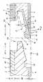
Mit 1 sind in der Zeichnung zwei Paneele für einen Parkettboden bezeichnet.Die Paneele 1 sind dreischichtig aufgebaut. Jedes Paneel 2 umfasst eineobere Trittschicht 2 aus einem Hartholz, wie beispielsweise Buche, Eicheoder Ahorn. An die Trittschicht 2 schließt sich eine gegenüber der Dicke Dder Trittschicht 2 dickere Zwischenschicht 3 aus einem gegenüber dem Materialder Trittschicht 2 weicheren Holz, wie beispielsweise Fichte, an. Aufder anderen Seite der Zwischenschicht 3 ist eine Basisschicht 4 ebenfallsaus einem gegenüber dem Material der Trittschicht 2 weicheren Material, wiez.B. Fichte, vorgesehen. Die Dicke D1 der Basisschicht 4 ist kleiner als dieDicke D2 der Zwischenschicht 3 bemessen.1 in the drawing denotes two panels for a parquet floor.The
Die Trittschicht 2 ist mit der Zwischenschicht 3 und die Zwischenschicht 3 istmit der Basisschicht 4 verleimt.The
Um zwei Paneele 1 spaltfrei problemlos miteinander verbinden zu können,ist an der einen Seite 19 des Rohkörpers RK eines Paneels 1 eine Rastzunge5 aus der Zwischenschicht 3 geformt.In order to be able to easily connect two
Auf der gegenüberliegenden Seite 8 weist jedes Paneel 1 eine an die Rastzunge5 angepasste Rastaufnahme 6 auf. Die Rastaufnahme 6 ist zumüberwiegenden Teil in einer Leiste 7 ausgebildet und nur zum geringen Teilin dem Material der Zwischenschicht 3. Die Leiste 7 besteht aus einem gegenüberdem Material der Zwischenschicht 3 härteren Material, wie beispielsweiseMDF-Material (mitteldichte Faserplatte) oder HDF-Material(hochverdichtete Faserplatte).On the
Zur Herstellung der Rastaufnahme 6 wird zunächst in den Rohkörper RK desPaneels 1, bestehend aus der Trittschicht 2, der Zwischenschicht 3 und derBasisschicht 4, von der Seite 8 her eine in strichpunktierter Linienführungangedeutete Nute 9 eingearbeitet, die unter einem Winkel α von 15° zur Oberfläche 10 der Trittschicht 2 verläuft. Die Nute 9 ist leicht keilförmig ausgebildet,wobei sie sich zur Mündung 11 in der Seite 8 hin verengt.To produce the catch 6 is first in the raw
Nach der Fertigung der Nute 9 wird in diese die Leiste 7 eingesetzt und verleimt.Ihre Unterseite 12 läuft in die Unterseite 13 der Basisschicht 4 ein.After the production of the
Danach wird durch eine spanabhebende Bearbeitung von Trittschicht 2, Zwischenschicht3 und Leiste 7 die Rastaufnahme 6 geformt, wodurch oberhalbder Rastaufnahme 6 eine Oberwange 14 und unterhalb der Rastaufnahme 6eine Unterwange 15 gebildet werden. Die Stirnseite 16 der Leiste 7 bildetdann zugleich die Stirnseite der Unterwange 15.Then, by machining the
Beim Zusammenfügen von zwei Paneelen 1 gemäß den Pfeilen PF und PF1fasst die Rastzunge 5 in die Rastaufnahme 6, wobei die endseitig der Leiste7 ausgebildete Rippe 17 nach vorübergehender Ausbiegung der Unterwange15 gemäß dem Pfeil PF2 dann in die rückwärtig der Rastzunge 5 im anderenPaneel 1 ausgebildete Ausnehmung 18 einfedert, so dass die beidenPaneele 1 zug- und druckfest miteinander verbunden sind.When joining two
- 1 -1 -
- Paneelepanels
- 2 -2 -
- Trittschichtwear layer
- 3 -3 -
- Zwischenschichtinterlayer
- 4 -4 -
- Basisschichtbase layer
- 5 -5 -
- Rastzungecatch tongue
- 6 -6 -
- Rastaufnahmelatching receptacle
- 7 -7 -
- Leiste mit 6Bar with 6
- 8 -8th -
- Seite v. 1Page v. 1
- 9 -9 -
- Nute f. 7Groove f. 7
- 10 -10 -
- Oberfläche v. 2Surface v. 2
- 11 -11 -
- Mündung v. 9
Estuary 9 - 12 -12 -
- Unterseite v. 7Bottom v. 7
- 13 -13 -
- Unterseite v. 4Bottom v. 4
- 14 -14 -
- Oberwangeupper beam
- 15 -15 -
- Unterwangelower beam
- 16 -16 -
- Stirnseite v. 7Front of v. 7
- 17 -17 -
- Rippe an 7Rib on 7th
- 18 -18 -
- Ausnehmung in 5Recess in 5
- 19 -19 -
- Seite v. 1Page v. 1
- α -α -
- Winkel v. 9Angle v. 9
- D -D -
- Dicke v. 2Thickness v. 2
- D1 -D1 -
- Dicke v. 4Thickness v. 4
- D2 -D2 -
- Dicke v. 3Thickness v. 3
- PF -PF -
- Pfeilarrow
- PF1 -PF1 -
- Pfeilarrow
- PF3 -PF3 -
- Pfeilarrow
- RK -RK -
- Rohkörper v. 1Raw body v. 1
Claims (8)
- A panel for a parquet floor made up of a treadlayer (2) of a hardwood and an intermediate layer(3) and counteracting means in the form of a baselayer (4) of woods softer than the material of thetread layer (2), and which, on at least one side(19), has a continuous catch tongue (5) and, on theopposite side (8), a catch recess (6) adapted to thecatch tongue (5), wherein the catch tongue (5) isformed from the material of the intermediate layer(3) and the catch recess (6) is formed substantiallyin a strip (7) which is fixed in the intermediatelayer (3) and which consists of a harder materialthan the intermediate layer (3).
- A panel according to claim 1, wherein the strip(7) is thinner than the intermediate layer (3),which latter is thicker than the tread layer (2) andthe base layer (4).
- A panel according to claim 1 or 2, wherein thestrip (7) extends at an angle (α) of about 15° tothe surface (10) of the tread layer (2).
- A panel according to any one of claims 1 to 3,wherein the strip (7) is fixed in a groove (9)formed at the edge of the intermediate layer (3).
- A panel according to claim 4, wherein thegroove (9) has a wedge-shaped cross-sectionnarrowing towards the opening (11).
- A panel according to any one of claims 1 to 5,wherein the underside (12) of the strip (7) runsinto the underside (13) of the base layer (4) andwith its end face (16) forms the end face of thebottom cheek (15) of the catch recess (6).
- A panel according to any one of claims 1 to 6,wherein the strip (7) is fixed in the intermediatelayer (3) by gluing.
- A method of making a panel (I) for a parquetfloor, wherein a tread layer (2) of hardwood isfirst joined to an intermediate layer (3) and to abase layer (4) of woods which are softer than thematerial of the tread layer (2) and then there isformed on at least one side (19) of the panel (1)from the intermediate layer (3) a catch tongue (5)and a groove (9) extending at an angle to thesurface (10) of the tread layer (2) is formed at theedge on the opposite side (8), into which groovethere is then inserted and fixed a strip (7) of aharder material than the material of theintermediate layer (3), whereupon a catch recess (6)adapted to the catch tongue (5) is made by chip-removalmachining of the intermediate layer (3) andof the strip (7).
Priority Applications (3)
| Application Number | Priority Date | Filing Date | Title |
|---|---|---|---|
| EP00118973AEP1184527B1 (en) | 2000-09-01 | 2000-09-01 | A parquet floor panel and method for manufacturing a panel for a parquet floor |
| AT00118973TATE272152T1 (en) | 2000-09-01 | 2000-09-01 | PANEL FOR A PARQUET FLOOR AND METHOD FOR PRODUCING A PANEL FOR A PARQUET FLOOR |
| DE50007215TDE50007215D1 (en) | 2000-09-01 | 2000-09-01 | Panel for a parquet floor and method for producing a panel for a parquet floor |
Applications Claiming Priority (1)
| Application Number | Priority Date | Filing Date | Title |
|---|---|---|---|
| EP00118973AEP1184527B1 (en) | 2000-09-01 | 2000-09-01 | A parquet floor panel and method for manufacturing a panel for a parquet floor |
Publications (2)
| Publication Number | Publication Date |
|---|---|
| EP1184527A1 EP1184527A1 (en) | 2002-03-06 |
| EP1184527B1true EP1184527B1 (en) | 2004-07-28 |
Family
ID=8169730
Family Applications (1)
| Application Number | Title | Priority Date | Filing Date |
|---|---|---|---|
| EP00118973AExpired - LifetimeEP1184527B1 (en) | 2000-09-01 | 2000-09-01 | A parquet floor panel and method for manufacturing a panel for a parquet floor |
Country Status (3)
| Country | Link |
|---|---|
| EP (1) | EP1184527B1 (en) |
| AT (1) | ATE272152T1 (en) |
| DE (1) | DE50007215D1 (en) |
Families Citing this family (5)
| Publication number | Priority date | Publication date | Assignee | Title |
|---|---|---|---|---|
| WO2004009931A1 (en)* | 2002-07-19 | 2004-01-29 | E.F.P. Floor Products Fussböden GmbH | Floor panel |
| WO2005103411A1 (en)* | 2004-04-20 | 2005-11-03 | Flooring Spectrum | Improved hardwood flooring board |
| PL2096230T3 (en) | 2008-02-26 | 2013-05-31 | Xylo Tech Ag | Multiply panel for floor, ceiling or wall coverings |
| WO2017219545A1 (en)* | 2016-06-25 | 2017-12-28 | 安吉恒丰竹木产品有限公司 | Composite floor having frame structure |
| EA202192054A1 (en)* | 2019-01-30 | 2021-12-31 | И4Ф Лайсенсинг Нв | PANEL AND COATING CONTAINING PANEL |
Family Cites Families (5)
| Publication number | Priority date | Publication date | Assignee | Title |
|---|---|---|---|---|
| US4426820A (en) | 1979-04-24 | 1984-01-24 | Heinz Terbrack | Panel for a composite surface and a method of assembling same |
| DE3343601C2 (en)* | 1983-12-02 | 1987-02-12 | Bütec Gesellschaft für bühnentechnische Einrichtungen mbH, 4010 Hilden | Removable flooring |
| US5295341A (en)* | 1992-07-10 | 1994-03-22 | Nikken Seattle, Inc. | Snap-together flooring system |
| BE1010487A6 (en) | 1996-06-11 | 1998-10-06 | Unilin Beheer Bv | FLOOR COATING CONSISTING OF HARD FLOOR PANELS AND METHOD FOR MANUFACTURING SUCH FLOOR PANELS. |
| SE512313E (en)* | 1998-06-03 | 2004-03-16 | Valinge Aluminium Ab | Locking system and floorboard |
- 2000
- 2000-09-01EPEP00118973Apatent/EP1184527B1/ennot_activeExpired - Lifetime
- 2000-09-01DEDE50007215Tpatent/DE50007215D1/ennot_activeExpired - Fee Related
- 2000-09-01ATAT00118973Tpatent/ATE272152T1/ennot_activeIP Right Cessation
Also Published As
| Publication number | Publication date |
|---|---|
| EP1184527A1 (en) | 2002-03-06 |
| DE50007215D1 (en) | 2004-09-02 |
| ATE272152T1 (en) | 2004-08-15 |
Similar Documents
| Publication | Publication Date | Title |
|---|---|---|
| EP3121348B1 (en) | Panel | |
| EP1350904B1 (en) | Floor planks | |
| EP1261785B1 (en) | Panel, in particular flooring panel | |
| DE102008031167B4 (en) | Method for connecting and locking glueless laying floor panels | |
| DE102009048050B3 (en) | Surface made of mechanical interconnectable elements | |
| DE602004010914T3 (en) | Set of floor panels | |
| DE10159284B4 (en) | Building plate, in particular floor panel | |
| US20160186445A1 (en) | Floor covering | |
| DE05077327T1 (en) | Floor covering consisting of hard floor panels and method of making such floor panels | |
| DE10302727A1 (en) | Positive-locking profile with two radii | |
| DE202006020940U1 (en) | Mechanical locking system for floor panels | |
| DE202007018935U1 (en) | flooring | |
| WO2002001018A1 (en) | Floor covering plate | |
| DE202007018804U1 (en) | Mechanical locking of floor panels | |
| DE202007013059U1 (en) | Floor element and consisting of such floor elements floor covering | |
| WO2004085765A1 (en) | Device for connecting building boards, especially floor panels | |
| DE202020102116U1 (en) | Decorative flooring system for gluing | |
| EP1681405A1 (en) | Floor panel | |
| DE60213360T2 (en) | Floor system with floor panels and method for connecting such panels | |
| EP1184527B1 (en) | A parquet floor panel and method for manufacturing a panel for a parquet floor | |
| EP1264946A1 (en) | Flooring panel | |
| EP1746218B1 (en) | Panel, particularly a floor panel | |
| EP3080365B1 (en) | Panel having a locking element | |
| CH683902A5 (en) | Composite sheet with at least one layer of wood - has central press plate with cover layer on each side consisting of courses of end-grain wood sections running at 75 - 15 deg. to under layer plane | |
| DE20109321U1 (en) | floor panel |
Legal Events
| Date | Code | Title | Description |
|---|---|---|---|
| PUAI | Public reference made under article 153(3) epc to a published international application that has entered the european phase | Free format text:ORIGINAL CODE: 0009012 | |
| 17P | Request for examination filed | Effective date:20010210 | |
| AK | Designated contracting states | Kind code of ref document:A1 Designated state(s):AT BE CH CY DE DK ES FI FR GB GR IE IT LI LU MC NL PT SE | |
| AX | Request for extension of the european patent | Free format text:AL;LT;LV;MK;RO;SI | |
| AKX | Designation fees paid | Free format text:AT BE CH CY DE DK ES FI FR GB GR IE IT LI LU MC NL PT SE | |
| GRAP | Despatch of communication of intention to grant a patent | Free format text:ORIGINAL CODE: EPIDOSNIGR1 | |
| GRAS | Grant fee paid | Free format text:ORIGINAL CODE: EPIDOSNIGR3 | |
| GRAA | (expected) grant | Free format text:ORIGINAL CODE: 0009210 | |
| AK | Designated contracting states | Kind code of ref document:B1 Designated state(s):AT BE CH CY DE DK ES FI FR GB GR IE IT LI LU MC NL PT SE | |
| PG25 | Lapsed in a contracting state [announced via postgrant information from national office to epo] | Ref country code:IT Free format text:LAPSE BECAUSE OF FAILURE TO SUBMIT A TRANSLATION OF THE DESCRIPTION OR TO PAY THE FEE WITHIN THE PRE;WARNING: LAPSES OF ITALIAN PATENTS WITH EFFECTIVE DATE BEFORE 2007 MAY HAVE OCCURRED AT ANY TIME BEFORE 2007. THE CORRECT EFFECTIVE DATE MAY BE DIFFERENT FROM THE ONE RECORDED.SCRIBED TIME-LIMIT Effective date:20040728 Ref country code:IE Free format text:LAPSE BECAUSE OF FAILURE TO SUBMIT A TRANSLATION OF THE DESCRIPTION OR TO PAY THE FEE WITHIN THE PRESCRIBED TIME-LIMIT Effective date:20040728 Ref country code:CY Free format text:LAPSE BECAUSE OF FAILURE TO SUBMIT A TRANSLATION OF THE DESCRIPTION OR TO PAY THE FEE WITHIN THE PRESCRIBED TIME-LIMIT Effective date:20040728 Ref country code:NL Free format text:LAPSE BECAUSE OF FAILURE TO SUBMIT A TRANSLATION OF THE DESCRIPTION OR TO PAY THE FEE WITHIN THE PRESCRIBED TIME-LIMIT Effective date:20040728 Ref country code:FI Free format text:LAPSE BECAUSE OF FAILURE TO SUBMIT A TRANSLATION OF THE DESCRIPTION OR TO PAY THE FEE WITHIN THE PRESCRIBED TIME-LIMIT Effective date:20040728 Ref country code:GB Free format text:LAPSE BECAUSE OF FAILURE TO SUBMIT A TRANSLATION OF THE DESCRIPTION OR TO PAY THE FEE WITHIN THE PRESCRIBED TIME-LIMIT Effective date:20040728 Ref country code:FR Free format text:LAPSE BECAUSE OF FAILURE TO SUBMIT A TRANSLATION OF THE DESCRIPTION OR TO PAY THE FEE WITHIN THE PRESCRIBED TIME-LIMIT Effective date:20040728 | |
| REG | Reference to a national code | Ref country code:GB Ref legal event code:FG4D Free format text:NOT ENGLISH | |
| REG | Reference to a national code | Ref country code:CH Ref legal event code:EP | |
| REG | Reference to a national code | Ref country code:IE Ref legal event code:FG4D Free format text:GERMAN | |
| PG25 | Lapsed in a contracting state [announced via postgrant information from national office to epo] | Ref country code:AT Free format text:LAPSE BECAUSE OF NON-PAYMENT OF DUE FEES Effective date:20040901 | |
| REF | Corresponds to: | Ref document number:50007215 Country of ref document:DE Date of ref document:20040902 Kind code of ref document:P | |
| PG25 | Lapsed in a contracting state [announced via postgrant information from national office to epo] | Ref country code:BE Free format text:LAPSE BECAUSE OF NON-PAYMENT OF DUE FEES Effective date:20040930 Ref country code:CH Free format text:LAPSE BECAUSE OF NON-PAYMENT OF DUE FEES Effective date:20040930 Ref country code:LU Free format text:LAPSE BECAUSE OF NON-PAYMENT OF DUE FEES Effective date:20040930 Ref country code:MC Free format text:LAPSE BECAUSE OF NON-PAYMENT OF DUE FEES Effective date:20040930 Ref country code:LI Free format text:LAPSE BECAUSE OF NON-PAYMENT OF DUE FEES Effective date:20040930 | |
| PG25 | Lapsed in a contracting state [announced via postgrant information from national office to epo] | Ref country code:GR Free format text:LAPSE BECAUSE OF FAILURE TO SUBMIT A TRANSLATION OF THE DESCRIPTION OR TO PAY THE FEE WITHIN THE PRESCRIBED TIME-LIMIT Effective date:20041028 Ref country code:DK Free format text:LAPSE BECAUSE OF FAILURE TO SUBMIT A TRANSLATION OF THE DESCRIPTION OR TO PAY THE FEE WITHIN THE PRESCRIBED TIME-LIMIT Effective date:20041028 Ref country code:SE Free format text:LAPSE BECAUSE OF FAILURE TO SUBMIT A TRANSLATION OF THE DESCRIPTION OR TO PAY THE FEE WITHIN THE PRESCRIBED TIME-LIMIT Effective date:20041028 | |
| PG25 | Lapsed in a contracting state [announced via postgrant information from national office to epo] | Ref country code:ES Free format text:LAPSE BECAUSE OF FAILURE TO SUBMIT A TRANSLATION OF THE DESCRIPTION OR TO PAY THE FEE WITHIN THE PRESCRIBED TIME-LIMIT Effective date:20041108 | |
| NLV1 | Nl: lapsed or annulled due to failure to fulfill the requirements of art. 29p and 29m of the patents act | ||
| GBV | Gb: ep patent (uk) treated as always having been void in accordance with gb section 77(7)/1977 [no translation filed] | Effective date:20040728 | |
| REG | Reference to a national code | Ref country code:IE Ref legal event code:FD4D | |
| BERE | Be: lapsed | Owner name:SCHULTE, JOHANNES Effective date:20040930 | |
| PG25 | Lapsed in a contracting state [announced via postgrant information from national office to epo] | Ref country code:DE Free format text:LAPSE BECAUSE OF NON-PAYMENT OF DUE FEES Effective date:20050401 | |
| REG | Reference to a national code | Ref country code:CH Ref legal event code:PL | |
| PLBE | No opposition filed within time limit | Free format text:ORIGINAL CODE: 0009261 | |
| STAA | Information on the status of an ep patent application or granted ep patent | Free format text:STATUS: NO OPPOSITION FILED WITHIN TIME LIMIT | |
| 26N | No opposition filed | Effective date:20050429 | |
| EN | Fr: translation not filed | ||
| BERE | Be: lapsed | Owner name:*SCHULTE JOHANNES Effective date:20040930 | |
| PG25 | Lapsed in a contracting state [announced via postgrant information from national office to epo] | Ref country code:PT Free format text:LAPSE BECAUSE OF NON-PAYMENT OF DUE FEES Effective date:20041228 |