EP1182552A2 - Dynamic hardware configuration for energy management systems using task attributes - Google Patents
Dynamic hardware configuration for energy management systems using task attributesDownload PDFInfo
- Publication number
- EP1182552A2 EP1182552A2EP00402946AEP00402946AEP1182552A2EP 1182552 A2EP1182552 A2EP 1182552A2EP 00402946 AEP00402946 AEP 00402946AEP 00402946 AEP00402946 AEP 00402946AEP 1182552 A2EP1182552 A2EP 1182552A2
- Authority
- EP
- European Patent Office
- Prior art keywords
- task
- processing
- circuitry
- processing module
- control word
- Prior art date
- Legal status (The legal status is an assumption and is not a legal conclusion. Google has not performed a legal analysis and makes no representation as to the accuracy of the status listed.)
- Withdrawn
Links
Images


Classifications
- G—PHYSICS
- G06—COMPUTING OR CALCULATING; COUNTING
- G06F—ELECTRIC DIGITAL DATA PROCESSING
- G06F9/00—Arrangements for program control, e.g. control units
- G06F9/06—Arrangements for program control, e.g. control units using stored programs, i.e. using an internal store of processing equipment to receive or retain programs
- G06F9/46—Multiprogramming arrangements
- G06F9/48—Program initiating; Program switching, e.g. by interrupt
- G06F9/4806—Task transfer initiation or dispatching
- G06F9/4843—Task transfer initiation or dispatching by program, e.g. task dispatcher, supervisor, operating system
- G06F9/4881—Scheduling strategies for dispatcher, e.g. round robin, multi-level priority queues
- G06F9/4893—Scheduling strategies for dispatcher, e.g. round robin, multi-level priority queues taking into account power or heat criteria
- G—PHYSICS
- G06—COMPUTING OR CALCULATING; COUNTING
- G06F—ELECTRIC DIGITAL DATA PROCESSING
- G06F1/00—Details not covered by groups G06F3/00 - G06F13/00 and G06F21/00
- G06F1/16—Constructional details or arrangements
- G06F1/20—Cooling means
- G06F1/206—Cooling means comprising thermal management
- G—PHYSICS
- G06—COMPUTING OR CALCULATING; COUNTING
- G06F—ELECTRIC DIGITAL DATA PROCESSING
- G06F1/00—Details not covered by groups G06F3/00 - G06F13/00 and G06F21/00
- G06F1/26—Power supply means, e.g. regulation thereof
- G06F1/32—Means for saving power
- G06F1/3203—Power management, i.e. event-based initiation of a power-saving mode
- G06F1/3234—Power saving characterised by the action undertaken
- G06F1/324—Power saving characterised by the action undertaken by lowering clock frequency
- G—PHYSICS
- G06—COMPUTING OR CALCULATING; COUNTING
- G06F—ELECTRIC DIGITAL DATA PROCESSING
- G06F1/00—Details not covered by groups G06F3/00 - G06F13/00 and G06F21/00
- G06F1/26—Power supply means, e.g. regulation thereof
- G06F1/32—Means for saving power
- G06F1/3203—Power management, i.e. event-based initiation of a power-saving mode
- G06F1/3234—Power saving characterised by the action undertaken
- G06F1/329—Power saving characterised by the action undertaken by task scheduling
- G—PHYSICS
- G06—COMPUTING OR CALCULATING; COUNTING
- G06F—ELECTRIC DIGITAL DATA PROCESSING
- G06F1/00—Details not covered by groups G06F3/00 - G06F13/00 and G06F21/00
- G06F1/26—Power supply means, e.g. regulation thereof
- G06F1/32—Means for saving power
- G06F1/3203—Power management, i.e. event-based initiation of a power-saving mode
- G06F1/3234—Power saving characterised by the action undertaken
- G06F1/3296—Power saving characterised by the action undertaken by lowering the supply or operating voltage
- G—PHYSICS
- G06—COMPUTING OR CALCULATING; COUNTING
- G06F—ELECTRIC DIGITAL DATA PROCESSING
- G06F11/00—Error detection; Error correction; Monitoring
- G06F11/30—Monitoring
- G06F11/34—Recording or statistical evaluation of computer activity, e.g. of down time, of input/output operation ; Recording or statistical evaluation of user activity, e.g. usability assessment
- G06F11/3409—Recording or statistical evaluation of computer activity, e.g. of down time, of input/output operation ; Recording or statistical evaluation of user activity, e.g. usability assessment for performance assessment
- G—PHYSICS
- G06—COMPUTING OR CALCULATING; COUNTING
- G06F—ELECTRIC DIGITAL DATA PROCESSING
- G06F12/00—Accessing, addressing or allocating within memory systems or architectures
- G06F12/02—Addressing or allocation; Relocation
- G06F12/0223—User address space allocation, e.g. contiguous or non contiguous base addressing
- G06F12/0292—User address space allocation, e.g. contiguous or non contiguous base addressing using tables or multilevel address translation means
- G—PHYSICS
- G06—COMPUTING OR CALCULATING; COUNTING
- G06F—ELECTRIC DIGITAL DATA PROCESSING
- G06F12/00—Accessing, addressing or allocating within memory systems or architectures
- G06F12/02—Addressing or allocation; Relocation
- G06F12/08—Addressing or allocation; Relocation in hierarchically structured memory systems, e.g. virtual memory systems
- G06F12/0802—Addressing of a memory level in which the access to the desired data or data block requires associative addressing means, e.g. caches
- G06F12/0877—Cache access modes
- G06F12/0879—Burst mode
- G—PHYSICS
- G06—COMPUTING OR CALCULATING; COUNTING
- G06F—ELECTRIC DIGITAL DATA PROCESSING
- G06F12/00—Accessing, addressing or allocating within memory systems or architectures
- G06F12/02—Addressing or allocation; Relocation
- G06F12/08—Addressing or allocation; Relocation in hierarchically structured memory systems, e.g. virtual memory systems
- G06F12/0802—Addressing of a memory level in which the access to the desired data or data block requires associative addressing means, e.g. caches
- G06F12/0891—Addressing of a memory level in which the access to the desired data or data block requires associative addressing means, e.g. caches using clearing, invalidating or resetting means
- G—PHYSICS
- G06—COMPUTING OR CALCULATING; COUNTING
- G06F—ELECTRIC DIGITAL DATA PROCESSING
- G06F12/00—Accessing, addressing or allocating within memory systems or architectures
- G06F12/02—Addressing or allocation; Relocation
- G06F12/08—Addressing or allocation; Relocation in hierarchically structured memory systems, e.g. virtual memory systems
- G06F12/10—Address translation
- G06F12/1027—Address translation using associative or pseudo-associative address translation means, e.g. translation look-aside buffer [TLB]
- G—PHYSICS
- G06—COMPUTING OR CALCULATING; COUNTING
- G06F—ELECTRIC DIGITAL DATA PROCESSING
- G06F9/00—Arrangements for program control, e.g. control units
- G06F9/06—Arrangements for program control, e.g. control units using stored programs, i.e. using an internal store of processing equipment to receive or retain programs
- G06F9/30—Arrangements for executing machine instructions, e.g. instruction decode
- G06F9/30003—Arrangements for executing specific machine instructions
- G06F9/3004—Arrangements for executing specific machine instructions to perform operations on memory
- G06F9/30043—LOAD or STORE instructions; Clear instruction
- G—PHYSICS
- G06—COMPUTING OR CALCULATING; COUNTING
- G06F—ELECTRIC DIGITAL DATA PROCESSING
- G06F12/00—Accessing, addressing or allocating within memory systems or architectures
- G06F12/02—Addressing or allocation; Relocation
- G06F12/08—Addressing or allocation; Relocation in hierarchically structured memory systems, e.g. virtual memory systems
- G06F12/10—Address translation
- G06F12/1081—Address translation for peripheral access to main memory, e.g. direct memory access [DMA]
- G—PHYSICS
- G06—COMPUTING OR CALCULATING; COUNTING
- G06F—ELECTRIC DIGITAL DATA PROCESSING
- G06F2201/00—Indexing scheme relating to error detection, to error correction, and to monitoring
- G06F2201/81—Threshold
- G—PHYSICS
- G06—COMPUTING OR CALCULATING; COUNTING
- G06F—ELECTRIC DIGITAL DATA PROCESSING
- G06F2201/00—Indexing scheme relating to error detection, to error correction, and to monitoring
- G06F2201/88—Monitoring involving counting
- G—PHYSICS
- G06—COMPUTING OR CALCULATING; COUNTING
- G06F—ELECTRIC DIGITAL DATA PROCESSING
- G06F2201/00—Indexing scheme relating to error detection, to error correction, and to monitoring
- G06F2201/885—Monitoring specific for caches
- G—PHYSICS
- G06—COMPUTING OR CALCULATING; COUNTING
- G06F—ELECTRIC DIGITAL DATA PROCESSING
- G06F2212/00—Indexing scheme relating to accessing, addressing or allocation within memory systems or architectures
- G06F2212/10—Providing a specific technical effect
- G06F2212/1028—Power efficiency
- Y—GENERAL TAGGING OF NEW TECHNOLOGICAL DEVELOPMENTS; GENERAL TAGGING OF CROSS-SECTIONAL TECHNOLOGIES SPANNING OVER SEVERAL SECTIONS OF THE IPC; TECHNICAL SUBJECTS COVERED BY FORMER USPC CROSS-REFERENCE ART COLLECTIONS [XRACs] AND DIGESTS
- Y02—TECHNOLOGIES OR APPLICATIONS FOR MITIGATION OR ADAPTATION AGAINST CLIMATE CHANGE
- Y02D—CLIMATE CHANGE MITIGATION TECHNOLOGIES IN INFORMATION AND COMMUNICATION TECHNOLOGIES [ICT], I.E. INFORMATION AND COMMUNICATION TECHNOLOGIES AIMING AT THE REDUCTION OF THEIR OWN ENERGY USE
- Y02D10/00—Energy efficient computing, e.g. low power processors, power management or thermal management
Definitions
- This inventionrelates in general to integrated circuits and, more particularly, to managing energy in a processor.
- processor designincluding designs for microprocessor units (MPUs), co-processors and digital signal processors (DSPs), has been to increase the speed and functionality of the processor.
- MPUsmicroprocessor units
- DSPsdigital signal processors
- energy consumptionhas become a serious issue.
- maintaining low energy consumption, without seriously impairing speed and functionalityhas moved to the forefront in many designs.
- Energy consumptionhas become important in many applications because many systems, such as smart phones, cellular phones, PDAs (personal digital assistants), and handheld computers operate from a relatively small battery. It is desirable to maximize the battery life in these systems, since it is inconvenient to recharge the batteries after short intervals.
- multiprocessor systemIn the future, applications executed by integrated circuits will be more complex and will likely involve multiprocessing by multiple processors, including MPUs, DSPs, coprocessors and DMA channels in a single integrated circuit (hereinafter, a "multiprocessor system"). DSPs will evolve to support multiple, concurrent applications, some of which will not be dedicated to a specific DSP platform, but will be loaded from a global network such as the Internet. Accordingly, the tasks that a multiprocessor system will be able to handle without overheating will become uncertain.
- a processing deviceincluding a processing module coupled to one or more associated circuits for supporting the processing module, where the processing module is capable of multitasking multiple tasks.
- a memorystores a control word for configuring the associated circuits, wherein each task has an associated control word which is stored in the memory while the task is being executed by the processing module.
- the present inventionprovides significant advantages over the prior art by providing for a fully dynamic energy management. As the tasks executed in the processing system change, circuits used by the task can be configured to an optimum configuration, thereby conserving energy.
- FIG. 1illustrates a general block diagram of a general multiprocessor system 10, including an MPU 12, one or more DSPs 14 and one or more DMA channels or coprocessors (shown collectively as DMA/Coprocessor 16).
- MPU 12includes a core 18 and a cache 20.
- the DSP 14includes a processing core 22 and a local memory 24 (an actual embodiment could use separate instruction and data memories, or could use a unified instruction and data memory).
- a memory interface 26couples a shared memory 28 to one or more of the MPU 12, DSP 14 or DMA/Coprocessor 16.
- Each processor (MPU 12, DSPs 14)can operate in full autonomy under its own operating system (OS) or real-time operating system (RTOS) in a real multiprocessor system, or the MPU 12 can operate the global OS that supervises shared resources and memory environment.
- OSoperating system
- RTOSreal-time operating system
- FIG. 2illustrates a software layer diagram for the multiprocessor system 10.
- the MPU 12executes the OS
- the DSP 14executes an RTOS.
- the OS and RTOSscomprise the OS layer 30 of the software.
- a distributed application layer 32includes JAVA, C++ and other applications 34, power management tasks 38 which use profiling data 36 and a global tasks scheduler 40.
- a middleware software layer 42communicates between the OS layer 30 and the applications in the distributed application layer 32.
- the multiprocessor system 10can execute a variety of tasks.
- a typical application for the multiprocessor system 10would be in a smartphone application where the multiprocessor system 10 handles wireless communication, video and audio decompression, and user interface (i.e., LCD update, keyboard decode).
- the different embedded systems in the multiprocessor system 10would be executing multiple tasks of different priorities.
- the OSwould perform the task scheduling of different tasks to the various embedded systems.
- the present inventionintegrates energy consumption as a criterion in scheduling tasks.
- the power management application 38 and profiles 36 from the distributed applications layer 32are used to build a system scenario, based on probabilistic values, for executing a list of tasks. If the scenario does not meet predetermined criteria, for example if the power consumption is too high, a new scenario is generated. After an acceptable scenario is established, the OS layer monitors the hardware activity to verify that the activity predicted in the scenario was accurate.
- the criteria for an acceptable task scheduling scenariocould vary depending upon the nature of the device.
- One important criterion for mobile devicesis minimum energy consumption. As stated above, as electronic communication devices are further miniaturized, the smaller battery allocation places a premium on energy consumption.
- a degraded operating mode for a taskmay be acceptable in order to reduce power, particularly as the batteries reach low levels. For example, reducing the LCD refresh rate will decrease power, albeit at the expense of picture quality.
- Another optionis to reduce the MIPs (millions of instructions per second) of the multiprocessor system 10 to reduce power, but at the cost of slower performance.
- the power management software 38can analyze different scenarios using different combinations of degraded performance to reach acceptable operation of the device.
- Another objective in managing powermay be to find the highest MIPs, or lowest energy for a given power limit setup.
- Figures 3a and 3billustrate an example of using the power management application 38 to prevent the multiprocessor system 10 from exceeding an average power dissipation limit.
- the DSP 14, DMA 16 and MPU 12are concurrently running a number of tasks.
- the average power dissipation of the three embedded systemsexceeds the average limit imposed on the multiprocessor system 10.
- Figure 3billustrates a scenario where the same tasks are executed; however, an MPU task is delayed until after the DMA and DSP tasks are completed in order to maintain an acceptable average power dissipation profile.
- Figure 4aillustrates a flow chart describing operation of a first embodiment of the power management tasks 38.
- the power management tasksare invoked by the global scheduler 40, which could be executed on the MPU 12 or one of the DSPs 14; the scheduler evaluate the upcoming application and splits it into tasks with associated precedence and exclusion rules.
- the task list 52could include, for example, audio/video decoding, display control, keyboard control, character recognition, and so on.
- the task list 52is evaluated in view of the task model file 56 and the accepted degradations file 58.
- the task model file 56is part of the profiles 36 of the distributed applications layer 32.
- the task model file 56is a previously generated file that assigns different models to each task in the task list.
- Each modelis a collection of data, which could be derived experimentally or by computer aided software design techniques, which defines characteristics of the associated task, such as latency constraints, priority, data flows, initial energy estimate at a reference processor speed, impacts of degradations, and an execution profile on a given processor as a function of MIPs and time.
- the degradation list 58sets forth the variety of degradations that can be used in generating the scenario.
- a scenariois built.
- the scenarioallocates the various tasks to the modules and provides priority information setting the priority with which tasks are executed.
- a scenario energy estimate 59 at a reference speedcan be computed from the tasks' energy estimate. If necessary or desirable, tasks may be degraded; i.e., a mode of the task that uses fewer resources may be substituted for the full version of a task. From this scenario, an activities estimate is generated in block 60.
- the activities estimateuses task activity profiles 62 (from the profiling data 36 of the distributed application layer 32) and a hardware architectural model 64 (also from the profiling data 36 of the distributed application layer 32) to generate probabilistic values for hardware activities that will result from the scenario.
- the probabilistic valuesinclude each module's wait/run time share (effective MHz), accesses to caches and memories, I/O toggling rates and DMA flow requests and data volume.
- Twait/run time share
- I/O toggling ratesand DMA flow requests and data volume.
- the scenariois rejected in decision block 74. In this case, a new scenario is built in block 54 and steps 60, 66 and 70 are repeated. Otherwise, the scenario is used to execute the task list.
- the OS and RTOSstrack activities by their respective modules in block 76 using counters 78 incorporated in the hardware.
- the actual activity in the modules of the multiprocessor system 10may vary from the activities estimated in block 60.
- the data from the hardware countersare monitored on a T periodic basis to produce measured activity values. These measured activity values are used in block 66 to compute an energy value for this period, and hence, an average power value in block 66, as described above, and are compared to the package thermal model in block 72. If the measured values exceed thresholds, then a new scenario is built in block 54.
- the scenarioscan be modified dynamically to stay within predefined limits or to adjust to changing environmental conditions.
- Total energy consumption over T for the chipis calculated as: where, f is the frequency, V dd is the supply voltage and ⁇ is the probabilistic (or measured, see discussion in connection with block 76 of this figure) activity.
- ⁇ T ( ⁇ ) *Cpd*f*V 2 / ddis the energy corresponding to a particular hardware module characterized by equivalent dissipation capacitance Cpd ; counters values give ⁇ T ( ⁇ ) and E is the sum of all energies for all modules in the multiprocessor system 10 dissipated within T.
- Average system power dissipation WE/T.
- measured and probabilistic energy consumptionis calculated and the average power dissipation is derived from the energy consumption over period T. In most cases, energy consumption information will be more readily available. However, it would also be possible to calculate the power dissipation from measured and probabilistic power consumption.
- Figure 4bis a flow chart describing operation of a second embodiment of the power management tasks 38.
- the flow of Figure 4bis the same as that of Figure 41, except when the scenario construction algorithm is invoked (new task, task delete, real time event) in step 50, instead of choosing one new scenario, n different scenarios that match the performances constraints can be pre-computed in advance and stored in steps 54 and 59, in order to reduce the number of operations within the dynamic loop and provide faster adaptation if the power computed in the tracking loop leads to current scenario rejection in block 74.
- the scenariois rejected, another pre-computed scenario is selected in block 65. Otherwise the operation is the same as shown in Figure 4a.
- FIGS 5 - 8illustrate the operation of various blocks of Figure 3 in greater detail.
- the build system block 54is shown in Figure 5.
- a task list 52In this block, a task list 52, a task model 56, and a list of possible task degradations 58 are used to generate a scenario.
- the task listis dependent upon which tasks are to be executed on the multiprocessor system 10.
- three tasksare shown: MPEG4 decode, wireless modem data receive and keyboard event monitor.
- the taskscould come from any number of sources.
- the task modelsets forth conditions which must be taken in consideration in defining the scenario, such as latency and priority constraints, data flow, initial energy estimates, and the impact of degradations. Other conditions could also be used in this block.
- the output of the build system scenario blockis a scenario 80, which associates the various tasks with the modules and assigns priorities to each of the tasks.
- the MPEG4 decode taskhas a priority of 16 and the wireless modem task has a priority of 4.
- the scenarios built in block 54could be based on a number of different considerations. For example, the scenarios could be built based on providing the maximum performance within the packages thermal constraints. Alternatively, the scenarios could be based on using the lowest possible energy. The optimum scenario could change during operation of a device; for example, with fully charged batteries a device may operate at a maximum performance level. As the power in the batteries diminished below a preset level, the device could operate at the lowest possible power level to sustain operation.
- the scenario 80 from block 54is used by the activities estimate block 60, shown in Figure 6.
- This blockperforms a probabilities computation for various parameters that affect power usage in the multiprocessor system 10.
- the probabilistic activities estimateis generated in conjunction with task activity profiles 62 and hardware architectural models 64.
- the task activity profilesinclude information on the data access types (load/store) and occurrences for the different memories, code profiles, such as the branches and loops used in the task, and the cycles per instruction for instructions in the task.
- the hardware architectural model 64describes in some way the impact of the task activity profiles 62 on the system latencies, that will permit computation of estimated hardware activities (such as processor run/wait time share).
- This modeltakes into account the characteristics of the hardware on which the task will be implemented, for example, the sizes of the caches, the width of various buses, the number of I/O pins, whether the cache is write-through or write back, the types of memories used (dynamic, static, flash, and so on) and the clock speeds used in the module.
- the modelcan consist of a family of curves that represent MPU and DSP effective frequency variations with different parameters, such as data cacheable/non-cacheable, read/write access shares, number of cycles per instruction, and so on.
- values for the effective frequency of each module, the number of memory accesses, the I/O toggling rates and the DMA floware calculated. Other factors that affect power could also be calculated.
- the power compute block 66is shown in Figure 8.
- the probabilistic activities from block 60 or the measured activities from block 76are used to compute various energy values and, hence, power values over a period T.
- the power valuesare computed in association with hardware power profiles, which are specific to the hardware design of the multiprocessor system 10.
- the hardware profilescould include a Cpd for each module, logic design style (D-type flip-flop, latches, gated clocks and so on), supply voltages and capacitive loads on the outputs. Power computations can be made for integrated modules, and also for external memory or other external devices.
- Activity measure and monitor block 76is shown in Figure 8. Counters are implemented throughout the multiprocessor system 10 to measure activities on the various modules, such as cache misses, TLB (translation lookaside buffer) misses, non-cacheable memory accesses, wait time, read/write requests for different resources, memory overhead and temperature.
- the activity measure and monitor block 76outputs values for the effective frequency of each module, the number of memory accesses, the I/O toggling rates and the DMA flow. In a particular implementation, other values may also be measured. The output of this block is sent to the power compute block 66.
- FIG 9illustrates and example of a multiprocessor system 10 using power/energy management software.
- the multiprocessor system 10includes a MPU 12, executing an OS, and two DSPs 14 (individually referenced as DSP1 14a and DSP2 14b), each executing a respective RTOS.
- Each moduleis executing a monitor task 82, which monitors the values in various activity counters 78 throughout the multiprocessor system 10.
- the power compute taskis executed on DSP 14a.
- the various monitor tasksretrieve data from associated activity counters 78 and pass the information to DSP 14a to calculate a power value based on measured activities.
- the power management taskssuch as power compute task 84 and monitor task 82, can be executed along with other application tasks.
- the power management tasks 38 and profiles 36are implemented as JAVA class packages in a JAVA real-time environment.
- the embodiment shown aboveprovides significant advantages over the prior art.
- the power managementcan build new scenarios to ensure that thresholds are not exceeded.
- environmental conditionssuch as battery voltages dropping
- the power management softwarecan re-evaluate conditions and change scenarios, if necessary. For example, if the battery voltage (supply voltage) dropped to a point where Vdd could not be sustained at its nominal value, a lower frequency could be established, which would allow operation of the multiprocessor system 10 at a lower Vdd. New scenarios could be built which would take the lower frequency into account. In some instances, more degradations would be introduced to compensate for the lower frequency.
- the lower frequencycould provide for continued operation of the device, despite supply voltages that would normally be insufficient. Further, in situations where a lower frequency was acceptable, the device could operate at a lower Vdd (with the availability of a switched mode supply) in order to conserve power during periods of relatively low activity.
- the power management softwareis transparent to the various tasks that it controls. Thus, even if a particular task does not provide for any power management, the power management software assumes responsibility for executing the task in a manner that is consistent with the power capabilities of the multiprocessor system 10.
- the overall operation of the power management softwarecan be used with different hardware platforms, with different hardware and tasks accommodated by changing the profiles 36.
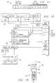
- FIG. 10illustrates a portion of a processing system 10, showing a detailed block diagram of an autonomous processor (MPU 12), coupled to a coprocessor 16 along with other peripheral devices 100a and 100b.
- MPU 12includes core circuitry 102, comprised of various core blocks 104a, 104b, and 104c. Core 102 further includes a Current Task ID register 106, a Task Priority register 108 and a Task Attributes register 110.
- Core 102is coupled to a cache subsystem 112, including and instruction RAMset cache 114, a local RAM 116, an n -way instruction cache 118, an n -way data cache 120, a DMA (direct memory access) channel 122, and microTLB (translation lookaside buffer) caches 122a, 122b, and 122c.
- MPU 12further includes voltage select circuitry 124 for selecting between two (or more) voltages to power the MPU 12.
- the cache subsystem 112 shown in Figure 10has several different caching circuits.
- the microTLBs 124a-care a small TLB structures that cache a few entries, used where a larger TLB (typically providing 64 entries or more) would penalize the speed of the processor.
- the n -way caches 118 and 120can be of conventional design (or could be a direct mapped cache).
- a RAMset cacheis designed to cache a contiguous block of memory starting from a chosen main memory address location.
- the RAMset cache 114can be designed as part of the n -way cache; for example, a 3way instruction cache 118 could be configured as one RAM set cache and a 2-way set associative cache.
- the particulars of the cache subsystem shown in Figure 10are provided only as an example; the cache subsystem could be varied by a circuit designer as desired.
- certain of the cache componentsmay not be needed, or the cache components may be configured for optimal operation.
- the voltage select circuitry 126provides a supply voltage to the MPU 12. As is well known in the art, the voltage needed to support processing circuitry is dependent upon several factors; temperature and frequency are two of the more significant factors. For tasks where a high frequency is not needed, the voltage can be lowered to reduce energy consumption in the processing system 10.
- Peripheral A 100acould be a input/output port, for example.
- Peripheral Bcould be a pointing device interface, such as a touch screen interface.
- the MPU core 102provides the processing function for MPU 12. This processing function is broken into multiple discrete blocks 104. Each block performs a function that may or may not be needed for a given task. For example, floating point arithmetic unit, a multiplier, auxiliary accumulator, saturated arithmetic unit, count-leading-zeros logic, and so on, could each be treated as a MPU Block 104.
- the Current Task ID register 106stores a unique identifier for the current task being executed on the MPU 12. Other autonomous processors would also have a Current Task ID register 106 and may be executing a task different from the current task executed by the MPU 12.
- the Task Priority register 108associates a priority with the task.
- the Task Attributes register 110stores a control word having fields which can enable/disable circuitry or configure circuitry to an optimum configuration.
- the operation of the Task Attributes register 110 to enable or disable circuitryis shown in connection with Figure 11.
- the data stored in the Task Attributes register 110has multiple fields which map to associated devices. For a simple on/off attribute, the field could be a single bit. Multiple bit fields can be provided for other functions, such as choosing between three or four voltages in the voltage select circuit 126.
- Each of the components shown in Figure 11 as being mapped to the Task Attributes register 110has circuitry that is responsive to a respective control field 128 in the register.
- the voltage select circuit 126one of multiple voltages is selected based on the value of the respective field 128.
- Vdd0could be chosen if the field is a "0" and Vdd1 could be chosen if the field is a "1".
- Vdd0could be chosen if the field is a "00” and Vdd1 could be chosen if the field is a "01”
- Vdd2could be chosen if the field is a "10”
- Vdd3could be chosen if the field is a "11".
- Coprocessor 16is shown as disabled (power off), along with peripheral A 100a, while peripheral B 100b is shown as enabled.
- Each of these deviceshas an associated power switching circuit that supplies power to the component responsive to the value of the associated field in Task Attributes register 110. Disabling power to a component that is not used in a task can significantly reduce the overall power consumed by the processing system 10.
- MPU block A 104a and MPU block C 104care enabled, while MPU block B 104b is disabled.
- a hardware resourcemay be coupled to multiple autonomous processors.
- a Level 2 shared memorymay be coupled to both the MPU and the DSP.
- the resourcecan be coupled to the Task Attributes register 110 of each processor, and the subsystem can be enabled or disabled based on a logical operation on the associated bit values. For example, assuming that a bit value of "1" represented an "on" state for the hardware subsystem, a logical OR operation on the task attribute bits would enable the resource if either processor was executing a task that needed the resource.
- Using the task attribute register as shown in Figure 11can significantly reduce the power consumed by the processing system 10 by disabling circuitry which is not used by a specific task.
- Figure 12illustrates a second scenario where the voltage to the MPU 12 is reduced.
- the Task Attributes register 110provides voltage Vdd0 to MPU 12. It is assumed that Vdd0 ⁇ Vdd1. To compensate for the reduction in supply voltage, the Task Attributes register 110 also configures the MPU blocks 104 to operate a lower frequency. Other subsystems in the MPU 12 may also be switched to a lower frequency due to the lower supply voltage.
- This aspect of the inventioncan significantly reduce power consumption where a processing element can perform a task at a frequency lower than its maximum frequency.
- FIGs 13a and 13billustrate the use of the Task Attributes register 110 to alter the configuration of the processing device 10 for more efficient operation.
- the MPU Core 102 and Cache subsystem 112are substantially the same as shown in Figures 10-12.
- a cache interface 130couples the cache subsystem 112 to a traffic controller 132. Traffic controller 130 and cache interface 132 control the flow of traffic between the system buses and the components of the cache subsystem 112.
- FIG. 13aillustrates a configuration where the currently executed task is computation intensive.
- the Task Attributes register 110is set to provide a 64-bit instruction path to the instruction cache 118 and the microTLB register 124a and a 128-bit bi-directional path to the microTLB 124b, data cache 120 and local RAM 116.
- MicroTLB 124c, DMA 122 and RAMset cache 114are turned off.
- a new taskis being executed resulting in a change in the task attribute register.
- the task shown in Figure 13ballocates high bandwidth to DMA transfer management, and a lower bandwidth for data and instruction transfers.
- a 64-bit input busis shared between the microTLB 124a/RAMset 114 instruction caches and the microTLB 124b/local RAM 116 data caches.
- the 128-bit bi-directional busis coupled to microTLB 124c and DMA circuit 122.
- the Task Attributes register 110could also configure the cache architecture.
- cache resourcescan be allocated between the instruction cache 118 and RAMset cache 114.
- the cache resourcescould be allocated as a 3-way set associative cache with a RAMset cache 114, a 2-way set associative cache with a larger RAMset cache, a 4-way set associative cache with no RAMset cache (as shown) or as a direct mapped cache with or without a RAMset cache 114.
- the most efficient cache architecturecould be chosen.
- Other hardwarecould be configured for maximum efficiency as well.
- some fields 128 in the Task Attributes register 110may configure the processing device 10 for a given scenario while others configure the device 10 for on each task.
- Scenario specific attribute fields 128aremain the same while tasks are switched.
- certain attributessuch as the core voltage to the processing device 10 or a system DMA controller, may be set for a scenario including several tasks which are being simultaneously executed by one or more processors.
- the scenario changesfor example when a new task is executed or when of the current tasks is terminated, a new scenario is created, and the scenario specific attributes may change.
- the task specific attribute fields 128b of Task Attributes register 110may switch during multitasking of several tasks in a scenario. Each time a task becomes the active task in a processing element of the processing system 10, the attribute fields of that task overwrite the task specific attribute fields of the previous active task (scenario specific attribute fields 128a unchanged).
- the task attribute fields for a given scenario and for each task in the scenariocan be generated by the global tasks scheduler 40 based on the task list 52 and associated profiles 36, as shown in Figures 4a and 4b.
- the energy savings provided by the ability to enable/disable hardware and to configure hardware for optimum performanceare taken into account in generating the scenario.
- An attribute wordis computed for each task and stored as part of the task's context information. Upon a context switch, the attribute word for the active task is loaded into the Task Attributes register 110. The Current Task ID register 106 and Task Priority register 108 are also loaded at this time.
- Figure 15illustrates a function diagram showing the creation of the data used for the Task Attributes register 110.
- the global task scheduler 40builds a scenario based on the task list 52 and associated models and profiles. Using this information, power and configuration attributes are computed for the run-time environment (the scenario attributes 128a) and also computes the priority information and the power and configuration attributes for the individual tasks in the scenario. For each task, the priority and attributes are stored in a respective task control block 129.
- Task control blocks 129may also contain other state information for the task that is restored upon the context switch.
- FIG 16illustrates an implementation of a mobile communications device 130 with microphone 132, speaker 134, keypad 136, display 138 and antenna 140.
- Internal processing circuitry 142includes one or more processing devices with the energy saving features described herein. It is contemplated, of course, that many other types of communications systems and computer systems may also benefit from the present invention, particularly those relying on battery power. Examples of such other computer systems include personal digital assistants (PDAS), portable computers, personal digital assistants (PDAs), smart phones, web phones, and the like. As power dissipation is also of concern in desktop and line-powered computer systems and micro-controller applications, particularly from a reliability standpoint, it is also contemplated that the present invention may also provide benefits to such line-powered systems.
- PDASpersonal digital assistants
- PDAspersonal digital assistants
- the present inventionmay also provide benefits to such line-powered systems.
- Telecommunications device 130includes microphone 132 for receiving audio input, and speaker 134 for outputting audible output, in the conventional manner.
- Microphone 132 and speaker 134are connected to processing circuitry 142, which receives and transmits audio and data signals.
Landscapes
- Engineering & Computer Science (AREA)
- Theoretical Computer Science (AREA)
- General Engineering & Computer Science (AREA)
- Physics & Mathematics (AREA)
- General Physics & Mathematics (AREA)
- Software Systems (AREA)
- Computer Hardware Design (AREA)
- Quality & Reliability (AREA)
- Human Computer Interaction (AREA)
- Power Sources (AREA)
- Memory System Of A Hierarchy Structure (AREA)
Abstract
Description
This invention relates in general to integrated circuits and, more particularly,to managing energy in a processor.
For many years, the focus of processor design, including designs formicroprocessor units (MPUs), co-processors and digital signal processors (DSPs), hasbeen to increase the speed and functionality of the processor. Presently, energyconsumption has become a serious issue. Importantly, maintaining low energyconsumption, without seriously impairing speed and functionality, has moved to theforefront in many designs. Energy consumption has become important in manyapplications because many systems, such as smart phones, cellular phones, PDAs(personal digital assistants), and handheld computers operate from a relatively smallbattery. It is desirable to maximize the battery life in these systems, since it isinconvenient to recharge the batteries after short intervals.
Currently, approaches to minimizing energy consumption involve staticenergy management; i.e., designing circuits which use less energy. In some cases,dynamic actions have been taken, such as reducing clock speeds or disablingcircuitry during idle periods.
While these changes have been important, it is necessary to continuouslyimprove energy management, especially in systems where size and, hence, batterysize, is important to the convenience of using a device.
In addition to overall energy savings, in a complex processing environment,the ability to dissipate heat from the integrated circuit becomes a factor. Anintegrated circuit will be designed to dissipate a certain amount of heat. If tasks(application processes) require multiple hardware systems on the integrated circuitto draw high levels of current, it is possible that the circuit will overheat, causingsystem failure.
In the future, applications executed by integrated circuits will be morecomplex and will likely involve multiprocessing by multiple processors, includingMPUs, DSPs, coprocessors and DMA channels in a single integrated circuit(hereinafter, a "multiprocessor system"). DSPs will evolve to support multiple,concurrent applications, some of which will not be dedicated to a specific DSPplatform, but will be loaded from a global network such as the Internet.Accordingly, the tasks that a multiprocessor system will be able to handle withoutoverheating will become uncertain.
Accordingly, a need has arisen for a method and apparatus for managingenergy in a circuit without seriously impacting performance.
In the present invention, a processing device is provided including aprocessing module coupled to one or more associated circuits for supporting theprocessing module, where the processing module is capable of multitasking multipletasks. A memory stores a control word for configuring the associated circuits,wherein each task has an associated control word which is stored in the memorywhile the task is being executed by the processing module.
The present invention provides significant advantages over the prior art byproviding for a fully dynamic energy management. As the tasks executed in theprocessing system change, circuits used by the task can be configured to an optimumconfiguration, thereby conserving energy.
For a more complete understanding of the present invention, and theadvantages thereof, reference is now made to the following descriptions taken inconjunction with the accompanying drawings, in which:
The present invention is best understood in relation to Figures 1-16 of thedrawings, like numerals being used for like elements of the various drawings.
Figure 1 illustrates a general block diagram of ageneral multiprocessor system 10, including anMPU 12, one or more DSPs 14 and one or more DMA channels orcoprocessors (shown collectively as DMA/Coprocessor 16). In this embodiment,MPU 12 includes acore 18 and acache 20. TheDSP 14 includes a processing core 22and a local memory 24 (an actual embodiment could use separate instruction anddata memories, or could use a unified instruction and data memory). Amemoryinterface 26 couples a sharedmemory 28 to one or more of theMPU 12,DSP 14 orDMA/Coprocessor 16. Each processor (MPU 12, DSPs 14) can operate in fullautonomy under its own operating system (OS) or real-time operating system(RTOS) in a real multiprocessor system, or theMPU 12 can operate the global OS thatsupervises shared resources and memory environment.
Figure 2 illustrates a software layer diagram for themultiprocessor system 10.As shown in Figure 1, theMPU 12 executes the OS, while theDSP 14 executes anRTOS. The OS and RTOSs comprise theOS layer 30 of the software. A distributedapplication layer 32 includes JAVA, C++ andother applications 34,powermanagement tasks 38 which useprofiling data 36 and aglobal tasks scheduler 40. Amiddleware software layer 42 communicates between theOS layer 30 and theapplications in the distributedapplication layer 32.
Referring to Figures 1 and 2, the operation of themultiprocessor system 10 isdiscussed. Themultiprocessor system 10 can execute a variety of tasks. A typicalapplication for themultiprocessor system 10 would be in a smartphone applicationwhere themultiprocessor system 10 handles wireless communication, video andaudio decompression, and user interface (i.e., LCD update, keyboard decode). In thisapplication, the different embedded systems in themultiprocessor system 10 wouldbe executing multiple tasks of different priorities. Typically, the OS would performthe task scheduling of different tasks to the various embedded systems.
The present invention integrates energy consumption as a criterion inscheduling tasks. In the preferred embodiment, thepower management application 38 andprofiles 36 from the distributedapplications layer 32 are used to build asystem scenario, based on probabilistic values, for executing a list of tasks. If thescenario does not meet predetermined criteria, for example if the power consumptionis too high, a new scenario is generated. After an acceptable scenario is established,the OS layer monitors the hardware activity to verify that the activity predicted in thescenario was accurate.
The criteria for an acceptable task scheduling scenario could vary dependingupon the nature of the device. One important criterion for mobile devices isminimum energy consumption. As stated above, as electronic communicationdevices are further miniaturized, the smaller battery allocation places a premium onenergy consumption. In many cases during the operation of a device, a degradedoperating mode for a task may be acceptable in order to reduce power, particularlyas the batteries reach low levels. For example, reducing the LCD refresh rate willdecrease power, albeit at the expense of picture quality. Another option is to reducethe MIPs (millions of instructions per second) of themultiprocessor system 10 toreduce power, but at the cost of slower performance. Thepower managementsoftware 38 can analyze different scenarios using different combinations of degradedperformance to reach acceptable operation of the device.
Another objective in managing power may be to find the highest MIPs, orlowest energy for a given power limit setup.
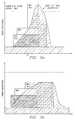
Figures 3a and 3b illustrate an example of using thepower managementapplication 38 to prevent themultiprocessor system 10 from exceeding an averagepower dissipation limit. In Figure 3a, theDSP 14,DMA 16 andMPU 12 areconcurrently running a number of tasks. At time t1, the average power dissipation ofthe three embedded systems exceeds the average limit imposed on themultiprocessor system 10. Figure 3b illustrates a scenario where the same tasks areexecuted; however, an MPU task is delayed until after the DMA and DSP tasks arecompleted in order to maintain an acceptable average power dissipation profile.
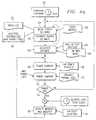
Figure 4a illustrates a flow chart describing operation of a first embodiment ofthepower management tasks 38. Inblock 50, the power management tasks areinvoked by theglobal scheduler 40, which could be executed on theMPU 12 or oneof theDSPs 14; the scheduler evaluate the upcoming application and splits it intotasks with associated precedence and exclusion rules. Thetask list 52 could include,for example, audio/video decoding, display control, keyboard control, characterrecognition, and so on. Instep 54, thetask list 52 is evaluated in view of thetaskmodel file 56 and the accepted degradations file 58. Thetask model file 56 is part oftheprofiles 36 of the distributedapplications layer 32. Thetask model file 56 is apreviously generated file that assigns different models to each task in the task list.Each model is a collection of data, which could be derived experimentally or bycomputer aided software design techniques, which defines characteristics of theassociated task, such as latency constraints, priority, data flows, initial energyestimate at a reference processor speed, impacts of degradations, and an executionprofile on a given processor as a function of MIPs and time. Thedegradation list 58sets forth the variety of degradations that can be used in generating the scenario.
Each time the task list is modified (i.e., a new task is created or a task isdeleted) or when a real time event occur, based on thetask list 52 and thetask model 56 instep 54, a scenario is built. The scenario allocates the various tasks to themodules and provides priority information setting the priority with which tasks areexecuted. Ascenario energy estimate 59 at a reference speed can be computed fromthe tasks' energy estimate. If necessary or desirable, tasks may be degraded; i.e., amode of the task that uses fewer resources may be substituted for the full version of atask. From this scenario, an activities estimate is generated inblock 60. The activitiesestimate uses task activity profiles 62 (from theprofiling data 36 of the distributedapplication layer 32) and a hardware architectural model 64 (also from theprofilingdata 36 of the distributed application layer 32) to generate probabilistic values forhardware activities that will result from the scenario. The probabilistic valuesinclude each module's wait/run time share (effective MHz), accesses to caches andmemories, I/O toggling rates and DMA flow requests and data volume. Using aperiod T that matches the thermal time constant, from theenergy estimate 59 at a reference processor speed and the average activities derived in step 60 (particularly,effective processors speeds), it is possible to compute an average power dissipationthat will be compared to thermal package model. If the power value exceeds anythresholds set forth in the packagethermal model 72, the scenario is rejected indecision block 74. In this case, a new scenario is built inblock 54 andsteps
During operation of the tasks as defined by the scenario, the OS and RTOSstrack activities by their respective modules inblock 76 usingcounters 78incorporated in the hardware. The actual activity in the modules of themultiprocessor system 10 may vary from the activities estimated inblock 60. Thedata from the hardware counters are monitored on a T periodic basis to producemeasured activity values. These measured activity values are used inblock 66 tocompute an energy value for this period, and hence, an average power value inblock 66, as described above, and are compared to the package thermal model inblock 72.If the measured values exceed thresholds, then a new scenario is built inblock 54. Bycontinuously monitoring the measured activity values, the scenarios can be modifieddynamically to stay within predefined limits or to adjust to changing environmentalconditions.
Total energy consumption over T for the chip is calculated as: where, f is the frequency, Vdd is the supply voltage and α is the probabilistic (ormeasured, see discussion in connection with
block 76 of this figure) activity. In otherwords,ΣT(α)*Cpd*f*V 2 /dd is the energy corresponding to a particular hardwaremodule characterized by equivalent dissipation capacitance Cpd ; counters valuesgive ΣT(α) and E is the sum of all energies for all modules in themultiprocessorsystem 10 dissipated within T. Average system power dissipation W = E/T. In thepreferred embodiment, measured and probabilistic energy consumption is calculatedand the average power dissipation is derived from the energy consumption overperiod T. In most cases, energy consumption information will be more readily available. However, it would also be possible to calculate the power dissipation frommeasured and probabilistic power consumption.

Figure 4b is a flow chart describing operation of a second embodiment of thepower management tasks 38. The flow of Figure 4b is the same as that of Figure 41,except when the scenario construction algorithm is invoked (new task, task delete,real time event) instep 50, instead of choosing one new scenario,n differentscenarios that match the performances constraints can be pre-computed in advanceand stored insteps block 74. In Figure 4b, if the scenario isrejected, another pre-computed scenario is selected inblock 65. Otherwise theoperation is the same as shown in Figure 4a.
Figures 5 - 8 illustrate the operation of various blocks of Figure 3 in greaterdetail. The build system block 54 is shown in Figure 5. In this block, atask list 52, atask model 56, and a list ofpossible task degradations 58 are used to generate ascenario. The task list is dependent upon which tasks are to be executed on themultiprocessor system 10. In the example of Figure 5, three tasks are shown: MPEG4decode, wireless modem data receive and keyboard event monitor. In an actualimplementation, the tasks could come from any number of sources. The task modelsets forth conditions which must be taken in consideration in defining the scenario,such as latency and priority constraints, data flow, initial energy estimates, and theimpact of degradations. Other conditions could also be used in this block. Theoutput of the build system scenario block is ascenario 80, which associates thevarious tasks with the modules and assigns priorities to each of the tasks. In theexample shown in Figure 5, for example, the MPEG4 decode task has a priority of 16and the wireless modem task has a priority of 4.
The scenarios built inblock 54 could be based on a number of differentconsiderations. For example, the scenarios could be built based on providing themaximum performance within the packages thermal constraints. Alternatively, the scenarios could be based on using the lowest possible energy. The optimum scenariocould change during operation of a device; for example, with fully charged batteriesa device may operate at a maximum performance level. As the power in the batteriesdiminished below a preset level, the device could operate at the lowest possiblepower level to sustain operation.
Thescenario 80 fromblock 54 is used by the activities estimateblock 60,shown in Figure 6. This block performs a probabilities computation for variousparameters that affect power usage in themultiprocessor system 10. Theprobabilistic activities estimate is generated in conjunction with task activity profiles62 and hardwarearchitectural models 64. The task activity profiles includeinformation on the data access types (load/store) and occurrences for the differentmemories, code profiles, such as the branches and loops used in the task, and thecycles per instruction for instructions in the task. The hardwarearchitectural model 64 describes in some way the impact of the task activity profiles 62 on the systemlatencies, that will permit computation of estimated hardware activities (such asprocessor run/wait time share). This model takes into account the characteristics ofthe hardware on which the task will be implemented, for example, the sizes of thecaches, the width of various buses, the number of I/O pins, whether the cache iswrite-through or write back, the types of memories used (dynamic, static, flash, andso on) and the clock speeds used in the module. Typically, the model can consist of afamily of curves that represent MPU and DSP effective frequency variations withdifferent parameters, such as data cacheable/non-cacheable, read/write accessshares, number of cycles per instruction, and so on. In the illustrated embodiment ofFigure 6, values for the effective frequency of each module, the number of memoryaccesses, the I/O toggling rates and the DMA flow are calculated. Other factors thataffect power could also be calculated.
Thepower compute block 66 is shown in Figure 8. In this block, theprobabilistic activities fromblock 60 or the measured activities fromblock 76 areused to compute various energy values and, hence, power values over a period T.The power values are computed in association with hardware power profiles, which are specific to the hardware design of themultiprocessor system 10. The hardwareprofiles could include a Cpd for each module, logic design style (D-type flip-flop,latches, gated clocks and so on), supply voltages and capacitive loads on the outputs.Power computations can be made for integrated modules, and also for externalmemory or other external devices.
Activity measure and monitorblock 76 is shown in Figure 8. Counters areimplemented throughout themultiprocessor system 10 to measure activities on thevarious modules, such as cache misses, TLB (translation lookaside buffer) misses,non-cacheable memory accesses, wait time, read/write requests for differentresources, memory overhead and temperature. The activity measure and monitorblock 76 outputs values for the effective frequency of each module, the number ofmemory accesses, the I/O toggling rates and the DMA flow. In a particularimplementation, other values may also be measured. The output of this block is sentto thepower compute block 66.
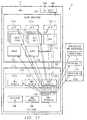
Figure 9 illustrates and example of amultiprocessor system 10 usingpower/energy management software. In this example, themultiprocessor system 10includes aMPU 12, executing an OS, and two DSPs 14 (individually referenced asDSP1 14a andDSP2 14b), each executing a respective RTOS. Each module isexecuting amonitor task 82, which monitors the values in various activity counters78 throughout themultiprocessor system 10. The power compute task is executed onDSP 14a. The various monitor tasks retrieve data from associated activity counters78 and pass the information toDSP 14a to calculate a power value based onmeasured activities. The power management tasks, such aspower compute task 84and monitortask 82, can be executed along with other application tasks.
In the preferred embodiment, thepower management tasks 38 andprofiles 36are implemented as JAVA class packages in a JAVA real-time environment.
The embodiment shown above provides significant advantages over the priorart. First, it provides for a fully dynamic power management. As the tasks executed in themultiprocessor system 10 change, the power management can build newscenarios to ensure that thresholds are not exceeded. Further, as environmentalconditions change, such as battery voltages dropping, the power managementsoftware can re-evaluate conditions and change scenarios, if necessary. For example,if the battery voltage (supply voltage) dropped to a point where Vdd could not besustained at its nominal value, a lower frequency could be established, which wouldallow operation of themultiprocessor system 10 at a lower Vdd. New scenarioscould be built which would take the lower frequency into account. In someinstances, more degradations would be introduced to compensate for the lowerfrequency. However, the lower frequency could provide for continued operation ofthe device, despite supply voltages that would normally be insufficient. Further, insituations where a lower frequency was acceptable, the device could operate at alower Vdd (with the availability of a switched mode supply) in order to conservepower during periods of relatively low activity.
The power management software is transparent to the various tasks that itcontrols. Thus, even if a particular task does not provide for any powermanagement, the power management software assumes responsibility for executingthe task in a manner that is consistent with the power capabilities of themultiprocessor system 10.
The overall operation of the power management software can be used withdifferent hardware platforms, with different hardware and tasks accommodated bychanging theprofiles 36.
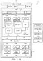
Figure 10 illustrates a portion of aprocessing system 10, showing a detailedblock diagram of an autonomous processor (MPU 12), coupled to acoprocessor 16along with otherperipheral devices MPU 12 includescore circuitry 102, comprised ofvarious core blocks Core 102 further includesa CurrentTask ID register 106, a Task Priority register 108 and a Task Attributesregister 110.Core 102 is coupled to acache subsystem 112, including andinstructionRAMset cache 114, alocal RAM 116, ann-way instruction cache 118, ann-way data cache 120, a DMA (direct memory access)channel 122, and microTLB (translationlookaside buffer) caches 122a, 122b, and 122c.MPU 12 further includes voltage selectcircuitry 124 for selecting between two (or more) voltages to power theMPU 12.
Thecache subsystem 112 shown in Figure 10 has several different cachingcircuits. ThemicroTLBs 124a-c are a small TLB structures that cache a few entries,used where a larger TLB (typically providing 64 entries or more) would penalize thespeed of the processor. Then-way caches RAMset cache 114 can be designed as part of then-way cache; for example, a3wayinstruction cache 118 could be configured as one RAM set cache and a 2-way setassociative cache. The particulars of the cache subsystem shown in Figure 10 areprovided only as an example; the cache subsystem could be varied by a circuitdesigner as desired.
For a given task, certain of the cache components may not be needed, or thecache components may be configured for optimal operation. For example, for acertain task, it may be desirable to configure a 4-way instruction cache as aRAMsetcache 114 and a 3-way set associative cache, while thedata cache 120 was configuredas a direct mapping cache.
The voltageselect circuitry 126 provides a supply voltage to theMPU 12. Asis well known in the art, the voltage needed to support processing circuitry isdependent upon several factors; temperature and frequency are two of the moresignificant factors. For tasks where a high frequency is not needed, the voltage canbe lowered to reduce energy consumption in theprocessing system 10.
One or more coprocessors and other peripheral devices may be used by theMPU 12 for various functions. Thecoprocessor 16 is used to provide high speedmathematical computations.Peripheral A 100a could be a input/output port, for example. Peripheral B could be a pointing device interface, such as a touch screeninterface.
TheMPU core 102 provides the processing function forMPU 12. Thisprocessing function is broken into multiplediscrete blocks 104. Each block performsa function that may or may not be needed for a given task. For example, floatingpoint arithmetic unit, a multiplier, auxiliary accumulator, saturated arithmetic unit,count-leading-zeros logic, and so on, could each be treated as aMPU Block 104.
The Current Task ID register 106 stores a unique identifier for the current taskbeing executed on theMPU 12. Other autonomous processors would also have aCurrentTask ID register 106 and may be executing a task different from the currenttask executed by theMPU 12. The Task Priority register 108 associates a prioritywith the task. The Task Attributes register 110 stores a control word having fieldswhich can enable/disable circuitry or configure circuitry to an optimumconfiguration.
The operation of the Task Attributes register 110 to enable or disable circuitryis shown in connection with Figure 11. The data stored in the Task Attributesregister 110 has multiple fields which map to associated devices. For a simple on/offattribute, the field could be a single bit. Multiple bit fields can be provided for otherfunctions, such as choosing between three or four voltages in the voltageselectcircuit 126.
Each of the components shown in Figure 11 as being mapped to the TaskAttributes register 110 has circuitry that is responsive to arespective control field 128in the register. For the voltageselect circuit 126, one of multiple voltages is selectedbased on the value of therespective field 128. In Figure 11, Vdd0 could be chosen ifthe field is a "0" and Vdd1 could be chosen if the field is a "1". For a voltage selectcircuit with four possible voltages, Vdd0 could be chosen if the field is a "00" andVdd1 could be chosen if the field is a "01", Vdd2 could be chosen if the field is a "10"and Vdd3 could be chosen if the field is a "11".
In some cases, a hardware resource may be coupled to multiple autonomousprocessors. For example, aLevel 2 shared memory may be coupled to both the MPUand the DSP. In cases where a hardware resource is shared between two or moreautonomous processors, the resource can be coupled to the Task Attributes register110 of each processor, and the subsystem can be enabled or disabled based on alogical operation on the associated bit values. For example, assuming that a bit valueof "1" represented an "on" state for the hardware subsystem, a logical OR operationon the task attribute bits would enable the resource if either processor was executinga task that needed the resource.
Using the task attribute register as shown in Figure 11 can significantly reducethe power consumed by theprocessing system 10 by disabling circuitry which is notused by a specific task.
Figure 12 illustrates a second scenario where the voltage to theMPU 12 isreduced. In Figure 12, the Task Attributes register 110 provides voltage Vdd0 toMPU 12. It is assumed that Vdd0<Vdd1. To compensate for the reduction in supplyvoltage, the Task Attributes register 110 also configures the MPU blocks 104 tooperate a lower frequency. Other subsystems in theMPU 12 may also be switched toa lower frequency due to the lower supply voltage.
This aspect of the invention can significantly reduce power consumptionwhere a processing element can perform a task at a frequency lower than itsmaximum frequency.
Figures 13a and 13b illustrate the use of the Task Attributes register 110 toalter the configuration of theprocessing device 10 for more efficient operation. Inthis embodiment, theMPU Core 102 andCache subsystem 112 are substantially thesame as shown in Figures 10-12. Acache interface 130 couples thecache subsystem 112 to atraffic controller 132.Traffic controller 130 andcache interface 132 controlthe flow of traffic between the system buses and the components of thecachesubsystem 112.
Importantly,cache interface 130 andtraffic controller 132 are designed suchthat the bandwidth to components in the cache subsystem can be varied as desired.For example, Figure 13a illustrates a configuration where the currently executed taskis computation intensive. In this configuration, the Task Attributes register 110 is setto provide a 64-bit instruction path to theinstruction cache 118 and themicroTLBregister 124a and a 128-bit bi-directional path to themicroTLB 124b,data cache 120andlocal RAM 116.MicroTLB 124c,DMA 122 andRAMset cache 114 are turned off.
In Figure 13b, a new task is being executed resulting in a change in the taskattribute register. The task shown in Figure 13b allocates high bandwidth to DMAtransfer management, and a lower bandwidth for data and instruction transfers.Accordingly, a 64-bit input bus is shared between themicroTLB 124a/RAMset 114instruction caches and themicroTLB 124b/local RAM 116 data caches. The 128-bitbi-directional bus is coupled tomicroTLB 124c andDMA circuit 122.
In addition to the bus configuration set by thecache interface 130 andtrafficcontroller 132, the Task Attributes register 110 could also configure the cachearchitecture. In Figure 13b, cache resources can be allocated between theinstructioncache 118 andRAMset cache 114. For example, the cache resources could beallocated as a 3-way set associative cache with aRAMset cache 114, a 2-way setassociative cache with a larger RAMset cache, a 4-way set associative cache with noRAMset cache (as shown) or as a direct mapped cache with or without aRAMsetcache 114. Depending upon the task (or scenario), the most efficient cache architecture could be chosen. Other hardware could be configured for maximumefficiency as well.
As shown in Figure 14, somefields 128 in the Task Attributes register 110 mayconfigure theprocessing device 10 for a given scenario while others configure thedevice 10 for on each task. Scenario specific attribute fields 128a remain the samewhile tasks are switched. For example, certain attributes, such as the core voltage totheprocessing device 10 or a system DMA controller, may be set for a scenarioincluding several tasks which are being simultaneously executed by one or moreprocessors. When the scenario changes, for example when a new task is executed orwhen of the current tasks is terminated, a new scenario is created, and the scenariospecific attributes may change.
The taskspecific attribute fields 128b of Task Attributes register 110, on theother hand, may switch during multitasking of several tasks in a scenario. Each timea task becomes the active task in a processing element of theprocessing system 10,the attribute fields of that task overwrite the task specific attribute fields of theprevious active task (scenario specific attribute fields 128a unchanged).
The task attribute fields for a given scenario and for each task in the scenariocan be generated by theglobal tasks scheduler 40 based on thetask list 52 andassociatedprofiles 36, as shown in Figures 4a and 4b. The energy savings providedby the ability to enable/disable hardware and to configure hardware for optimumperformance are taken into account in generating the scenario. An attribute word iscomputed for each task and stored as part of the task's context information. Upon acontext switch, the attribute word for the active task is loaded into the TaskAttributes register 110. The CurrentTask ID register 106 and Task Priority register108 are also loaded at this time.
Figure 15 illustrates a function diagram showing the creation of the data usedfor the Task Attributes register 110. Upon the creation or deletion of a task, theglobal task scheduler 40 builds a scenario based on thetask list 52 and associated models and profiles. Using this information, power and configuration attributes arecomputed for the run-time environment (the scenario attributes 128a) and alsocomputes the priority information and the power and configuration attributes for theindividual tasks in the scenario. For each task, the priority and attributes are storedin a respectivetask control block 129. Upon a context switch, where tasks arechanged for a given processor, the information in the task control block for the newtask are loaded into the appropriate registers. Task control blocks 129 may alsocontain other state information for the task that is restored upon the context switch.
Figure 16 illustrates an implementation of amobile communications device 130 withmicrophone 132,speaker 134,keypad 136,display 138 andantenna 140.Internal processing circuitry 142 includes one or more processing devices with theenergy saving features described herein. It is contemplated, of course, that manyother types of communications systems and computer systems may also benefit fromthe present invention, particularly those relying on battery power. Examples of suchother computer systems include personal digital assistants (PDAS), portablecomputers, personal digital assistants (PDAs), smart phones, web phones, and thelike. As power dissipation is also of concern in desktop and line-powered computersystems and micro-controller applications, particularly from a reliability standpoint,it is also contemplated that the present invention may also provide benefits to suchline-powered systems.
Although the Detailed Description of the invention has been directed tocertain exemplary embodiments, various modifications of these embodiments, aswell as alternative embodiments, will be suggested to those skilled in the art. Theinvention encompasses any modifications or alternative embodiments that fall withinthe scope of the Claims.
Claims (25)
1. A processing device comprising:
a processing module capable of multitasking multiple tasks;
one or more associated circuits, which may be selectively configuredresponsive to control signal, coupled to said processing module for supporting theprocessing module; and
a memory storing a control word for configuring the associated circuits,wherein each task has an associated control word which is stored in the memorywhile the task is being executed by the processing module.
2. The processing device of claim 1 wherein said control word comprises aplurality of fields.
3. The processing device of claim 2 wherein each of said associatedcircuits has an associated field.
4. The processing device of claim 3 wherein each of said associatedcircuits has configuration circuitry for configuring the associated circuit responsive toa value stored in said associated field.
5. The processing device of claim 4 wherein said configuration circuitrycomprises frequency control circuitry.
6. The processing circuitry of claim 4 wherein said configuration circuitrycomprises voltage selection circuitry.
7. The processing circuitry of claim 4 wherein said configuration circuitrycomprises interface circuitry for selecting one of a plurality of data paths.
8. The processing circuitry of claim 4 wherein said configuration circuitrycomprises cache configuration circuitry.
9. The processing device of claim 1 wherein said processing moduleincludes a plurality of processing subsystems which may be selectively configuredby said control word.
10. The processing device of claim 1 wherein said processing module is amicroprocessor module.
11. The processing device of claim 1 wherein said processing module is adigital signal processor.
12. The processing device of claim 1 wherein at least one of said associatedcircuits is a caching circuit.
13. The processing device of claim 8 wherein one of said associated circuitsis an interface to the caching circuit.
14. The processing device of claim 1 wherein said processing modulecomprises a first processing module, and further comprising one or more additionalprocessing modules.
15. A method of operating a processing device including a processingmodule capable of multitasking multiple tasks coupled to one or more associatedcircuits, comprising the steps of:
identifying a current task; and
storing a control word associated with said current task in a memory; and
configuring the associated circuits to a state responsive to the control wordduring execution of said current task.
16. The method of claim 15 wherein said storing step comprises the step ofstoring a control word having a plurality of predefined fields.
17. The method of claim 16 wherein each of said associated circuits has anassociated field in said control word.
18. The method of claim 17 wherein said enabling or disabling stepcomprises the step of configuring each of the associated circuits responsive to a valuestored in said associated field.
20. The method of claim 19 wherein said configuration step comprises thestep of controlling the frequency of said associated circuitry.
21. The method of claim 19 wherein said configuration step comprises thestep of selecting a voltage.
22. The method of claim 19 wherein said configuration step comprises thestep of selecting one of a plurality of data path configurations to said associatedcircuitry.
23. The method of claim 19 wherein said configuration circuitry comprisesconfiguring a cache.
24. The method of claim 15 wherein said processing module includes aplurality of processing subsystems and further comprising the step of configuringsaid processing subsystems responsive to said control word.
25. A processing device comprising:
multiple processing modules each capable of multitasking multiple tasks;
one or more associated circuits shared between two or more processingmodules, which may be selectively configured responsive to a control signal, coupledto said processing modules for supporting the processing module;
multiple memories associated with respective processing modules for storinga control word for enabling and disabling the associated circuits, wherein each taskhas an associated control word which is stored in the memory while the task is beingexecuted by the processing module.
26. A mobile communications device comprising:
an antenna for receiving and transmitting signals; and
receiver/transmitter circuitry for receiving and transmitting audio and datasignals, said receiver/transmitter circuitry comprising:
a processing module capable of multitasking multiple tasks;
one or more associated circuits, which may be selectively configuredresponsive to control signal, coupled to said processing module for supporting the processing module; and
a memory storing a control word for configuring the associated circuits,wherein each task has an associated control word which is stored in the memorywhile the task is being executed by the processing module.
Priority Applications (2)
| Application Number | Priority Date | Filing Date | Title |
|---|---|---|---|
| EP20000402946EP1182552A3 (en) | 2000-08-21 | 2000-10-24 | Dynamic hardware configuration for energy management systems using task attributes |
| US09/932,354US6889330B2 (en) | 2000-08-21 | 2001-08-17 | Dynamic hardware configuration for energy management systems using task attributes |
Applications Claiming Priority (3)
| Application Number | Priority Date | Filing Date | Title |
|---|---|---|---|
| EP00402331 | 2000-08-21 | ||
| EP00402331AEP1182559B1 (en) | 2000-08-21 | 2000-08-21 | Improved microprocessor |
| EP20000402946EP1182552A3 (en) | 2000-08-21 | 2000-10-24 | Dynamic hardware configuration for energy management systems using task attributes |
Publications (2)
| Publication Number | Publication Date |
|---|---|
| EP1182552A2true EP1182552A2 (en) | 2002-02-27 |
| EP1182552A3 EP1182552A3 (en) | 2003-10-01 |
Family
ID=26073543
Family Applications (1)
| Application Number | Title | Priority Date | Filing Date |
|---|---|---|---|
| EP20000402946WithdrawnEP1182552A3 (en) | 2000-08-21 | 2000-10-24 | Dynamic hardware configuration for energy management systems using task attributes |
Country Status (2)
| Country | Link |
|---|---|
| US (1) | US6889330B2 (en) |
| EP (1) | EP1182552A3 (en) |
Cited By (28)
| Publication number | Priority date | Publication date | Assignee | Title |
|---|---|---|---|---|
| GB2392271A (en)* | 2002-08-12 | 2004-02-25 | Hewlett Packard Development Co | In a multiprocessor operating a first processor at a first voltage level and a second processor at a second voltage level |
| GB2392270A (en)* | 2002-08-12 | 2004-02-25 | Hewlett Packard Development Co | Operating a first processor at a first voltage for a first performance level and a second processor at a second voltage for a second performance level |
| GB2392267A (en)* | 2002-08-12 | 2004-02-25 | Hewlett Packard Development Co | Voltage management in a multiprocessor system. |
| GB2392268A (en)* | 2002-08-12 | 2004-02-25 | Hewlett Packard Development Co | Managing the voltage level of at least one processor in a group of processors based on the number of processors loaded and the thermal and power envelope |
| WO2005026965A1 (en)* | 2003-09-11 | 2005-03-24 | Intel Corporation | Adaptive cache algorithm for temperature sensitive memory |
| WO2005088443A3 (en)* | 2004-03-16 | 2006-01-19 | Sony Computer Entertainment Inc | Methods and apparatus for reducing power dissipation in a multi-processor system |
| WO2006014254A1 (en)* | 2004-07-02 | 2006-02-09 | Intel Corporation | An apparatus and method for heterogenous chip multiprocessors via resource allocation and restriction |
| EP1653332A3 (en)* | 2004-09-30 | 2006-05-31 | Kabushiki Kaisha Toshiba | Multiprocessor computer for task distribution with heat emission levelling |
| WO2007066058A1 (en)* | 2005-12-06 | 2007-06-14 | Arm Limited | Energy management |
| WO2007072435A3 (en)* | 2005-12-21 | 2007-11-01 | Nxp Bv | Reducingthe number of memory banks being powered |
| US7360102B2 (en) | 2004-03-29 | 2008-04-15 | Sony Computer Entertainment Inc. | Methods and apparatus for achieving thermal management using processor manipulation |
| US7516334B2 (en) | 2001-03-22 | 2009-04-07 | Sony Computer Entertainment Inc. | Power management for processing modules |
| US8224639B2 (en) | 2004-03-29 | 2012-07-17 | Sony Computer Entertainment Inc. | Methods and apparatus for achieving thermal management using processing task scheduling |
| WO2013173001A1 (en)* | 2012-05-14 | 2013-11-21 | Qualcomm Incorporated | Monitoring behavioral features in a mobile multiprocessor platform |
| US9298494B2 (en) | 2012-05-14 | 2016-03-29 | Qualcomm Incorporated | Collaborative learning for efficient behavioral analysis in networked mobile device |
| US9319897B2 (en) | 2012-08-15 | 2016-04-19 | Qualcomm Incorporated | Secure behavior analysis over trusted execution environment |
| US9324034B2 (en) | 2012-05-14 | 2016-04-26 | Qualcomm Incorporated | On-device real-time behavior analyzer |
| US9330257B2 (en) | 2012-08-15 | 2016-05-03 | Qualcomm Incorporated | Adaptive observation of behavioral features on a mobile device |
| US9491187B2 (en) | 2013-02-15 | 2016-11-08 | Qualcomm Incorporated | APIs for obtaining device-specific behavior classifier models from the cloud |
| US9495537B2 (en) | 2012-08-15 | 2016-11-15 | Qualcomm Incorporated | Adaptive observation of behavioral features on a mobile device |
| US9609456B2 (en) | 2012-05-14 | 2017-03-28 | Qualcomm Incorporated | Methods, devices, and systems for communicating behavioral analysis information |
| US9686023B2 (en) | 2013-01-02 | 2017-06-20 | Qualcomm Incorporated | Methods and systems of dynamically generating and using device-specific and device-state-specific classifier models for the efficient classification of mobile device behaviors |
| US9684870B2 (en) | 2013-01-02 | 2017-06-20 | Qualcomm Incorporated | Methods and systems of using boosted decision stumps and joint feature selection and culling algorithms for the efficient classification of mobile device behaviors |
| US9690635B2 (en) | 2012-05-14 | 2017-06-27 | Qualcomm Incorporated | Communicating behavior information in a mobile computing device |
| US9742559B2 (en) | 2013-01-22 | 2017-08-22 | Qualcomm Incorporated | Inter-module authentication for securing application execution integrity within a computing device |
| US9747440B2 (en) | 2012-08-15 | 2017-08-29 | Qualcomm Incorporated | On-line behavioral analysis engine in mobile device with multiple analyzer model providers |
| US10089582B2 (en) | 2013-01-02 | 2018-10-02 | Qualcomm Incorporated | Using normalized confidence values for classifying mobile device behaviors |
| CN119621517A (en)* | 2025-02-12 | 2025-03-14 | 珠海全球时代科技有限公司 | Energy consumption prediction and optimization method of smart card chip and related device |
Families Citing this family (53)
| Publication number | Priority date | Publication date | Assignee | Title |
|---|---|---|---|---|
| EP1182552A3 (en)* | 2000-08-21 | 2003-10-01 | Texas Instruments France | Dynamic hardware configuration for energy management systems using task attributes |
| EP1182556B1 (en)* | 2000-08-21 | 2009-08-19 | Texas Instruments France | Task based adaptive profiling and debugging |
| EP1182548A3 (en)* | 2000-08-21 | 2003-10-15 | Texas Instruments France | Dynamic hardware control for energy management systems using task attributes |
| US7174194B2 (en)* | 2000-10-24 | 2007-02-06 | Texas Instruments Incorporated | Temperature field controlled scheduling for processing systems |
| TWI262380B (en)* | 2002-04-25 | 2006-09-21 | Quanta Comp Inc | Dynamic adjustment method for power consumption of computer system |
| US8032891B2 (en)* | 2002-05-20 | 2011-10-04 | Texas Instruments Incorporated | Energy-aware scheduling of application execution |
| US6950904B2 (en)* | 2002-06-25 | 2005-09-27 | Intel Corporation | Cache way replacement technique |
| TW556421B (en)* | 2002-08-15 | 2003-10-01 | Htc Corp | Circuit and operating method for integrated interface of PDA and wireless communication system |
| KR101053010B1 (en) | 2003-05-07 | 2011-07-29 | 모사이드 테크놀로지스, 인코포레이티드 | Managing power on integrated circuits using power islands |
| US7089397B1 (en) | 2003-07-03 | 2006-08-08 | Transmeta Corporation | Method and system for caching attribute data for matching attributes with physical addresses |
| JP4477380B2 (en)* | 2004-03-02 | 2010-06-09 | Necエレクトロニクス株式会社 | Multi-layer system and clock control method |
| CN101019089A (en)* | 2004-03-22 | 2007-08-15 | 皇家飞利浦电子股份有限公司 | Method and apparatus for power management in mobile terminals |
| US7549177B2 (en)* | 2005-03-28 | 2009-06-16 | Intel Corporation | Advanced thermal management using an average power controller over an adjustable time window |
| US7472301B2 (en)* | 2005-05-27 | 2008-12-30 | Codman Neuro Sciences Sárl | Circuitry for optimization of power consumption in a system employing multiple electronic components, one of which is always powered on |
| US20070008887A1 (en)* | 2005-06-24 | 2007-01-11 | Eugene Gorbatov | Platform power management of a computing device using quality of service requirements of software tasks |
| US7337339B1 (en) | 2005-09-15 | 2008-02-26 | Azul Systems, Inc. | Multi-level power monitoring, filtering and throttling at local blocks and globally |
| WO2007049100A1 (en)* | 2005-10-27 | 2007-05-03 | Freescale Semiconductor, Inc. | System and method for controlling voltage level and clock frequency supplied to a system |
| US7376532B2 (en)* | 2005-11-29 | 2008-05-20 | International Business Machines Corporation | Maximal temperature logging |
| US7386414B2 (en)* | 2005-11-29 | 2008-06-10 | International Business Machines Corporation | Generation of hardware thermal profiles for a set of processors |
| US7460932B2 (en)* | 2005-11-29 | 2008-12-02 | International Business Machines Corporation | Support of deep power savings mode and partial good in a thermal management system |
| US7603576B2 (en)* | 2005-11-29 | 2009-10-13 | International Business Machines Corporation | Hysteresis in thermal throttling |
| US7512513B2 (en)* | 2005-11-29 | 2009-03-31 | International Business Machines Corporation | Thermal throttling control for testing of real-time software |
| US7681053B2 (en)* | 2005-11-29 | 2010-03-16 | International Business Machines Corporation | Thermal throttle control with minimal impact to interrupt latency |
| US20070124618A1 (en)* | 2005-11-29 | 2007-05-31 | Aguilar Maximino Jr | Optimizing power and performance using software and hardware thermal profiles |
| US7848901B2 (en)* | 2005-11-29 | 2010-12-07 | International Business Machines Corporation | Tracing thermal data via performance monitoring |
| US7512530B2 (en)* | 2005-11-29 | 2009-03-31 | International Business Machines Corporation | Generation of software thermal profiles for applications in a simulated environment |
| US7698089B2 (en)* | 2005-11-29 | 2010-04-13 | International Business Machines Corporation | Generation of software thermal profiles executed on a set of processors using processor activity |
| US7721128B2 (en)* | 2005-11-29 | 2010-05-18 | International Business Machines Corporation | Implementation of thermal throttling logic |
| US7851985B2 (en)* | 2006-03-31 | 2010-12-14 | General Electric Company | Article incorporating a high temperature ceramic composite for selective emission |
| US8037893B2 (en)* | 2006-05-03 | 2011-10-18 | International Business Machines Corporation | Optimizing thermal performance using thermal flow analysis |
| US7552346B2 (en)* | 2006-05-03 | 2009-06-23 | International Business Machines Corporation | Dynamically adapting software for reducing a thermal state of a processor core based on its thermal index |
| US7596430B2 (en)* | 2006-05-03 | 2009-09-29 | International Business Machines Corporation | Selection of processor cores for optimal thermal performance |
| US20070260894A1 (en)* | 2006-05-03 | 2007-11-08 | Aguilar Maximino Jr | Optimizing thermal performance using feed-back directed optimization |
| WO2007148159A1 (en) | 2006-06-22 | 2007-12-27 | Freescale Semiconductor, Inc. | A method and device for power management |
| US7774520B2 (en)* | 2006-12-19 | 2010-08-10 | Intel Corporation | Method and apparatus for maintaining synchronization of audio in a computing system |
| US8027798B2 (en)* | 2007-11-08 | 2011-09-27 | International Business Machines Corporation | Digital thermal sensor test implementation without using main core voltage supply |
| US20110170580A1 (en)* | 2008-01-29 | 2011-07-14 | Wavesat Inc. | Signal processing unit and method, and corresponding transceiver |
| US20090222832A1 (en)* | 2008-02-29 | 2009-09-03 | Dell Products, Lp | System and method of enabling resources within an information handling system |
| JP4900289B2 (en)* | 2008-03-06 | 2012-03-21 | 富士通株式会社 | Electronic device and system startup method |
| JP5056570B2 (en)* | 2008-05-02 | 2012-10-24 | 富士通株式会社 | Data processing apparatus, data processing method, and data processing program |
| US8458722B2 (en)* | 2008-06-09 | 2013-06-04 | International Business Machines Corporation | Thread selection according to predefined power characteristics during context switching on compute nodes |
| US20100161368A1 (en)* | 2008-12-23 | 2010-06-24 | International Business Machines Corporation | Managing energy in a data center |
| US8799690B2 (en) | 2009-06-21 | 2014-08-05 | International Business Machines Corporation | Prioritized workload routing in a data center |
| US8479215B2 (en)* | 2009-08-18 | 2013-07-02 | International Business Machines Corporation | Decentralized load distribution to reduce power and/or cooling costs in an event-driven system |
| US8479216B2 (en)* | 2009-08-18 | 2013-07-02 | International Business Machines Corporation | Method for decentralized load distribution in an event-driven system using localized migration between physically connected nodes and load exchange protocol preventing simultaneous migration of plurality of tasks to or from a same node |
| US8776066B2 (en)* | 2009-11-30 | 2014-07-08 | International Business Machines Corporation | Managing task execution on accelerators |
| US9374787B2 (en)* | 2011-02-10 | 2016-06-21 | Alcatel Lucent | Method and apparatus of smart power management for mobile communication terminals using power thresholds |
| US20120210150A1 (en)* | 2011-02-10 | 2012-08-16 | Alcatel-Lucent Usa Inc. | Method And Apparatus Of Smart Power Management For Mobile Communication Terminals |
| US8966300B2 (en) | 2011-10-04 | 2015-02-24 | Ericsson Modems Sa | DFVS-enabled multiprocessor |
| JP5942416B2 (en)* | 2011-12-21 | 2016-06-29 | 富士通株式会社 | Information processing apparatus control program, control method, and information processing apparatus |
| US9575542B2 (en)* | 2013-01-31 | 2017-02-21 | Hewlett Packard Enterprise Development Lp | Computer power management |
| US9268898B1 (en)* | 2013-03-12 | 2016-02-23 | Xilinx, Inc. | Estimating power consumption of a circuit design |
| US9921633B2 (en)* | 2014-08-22 | 2018-03-20 | Intel Corporation | Power aware job scheduler and manager for a data processing system |
Family Cites Families (24)
| Publication number | Priority date | Publication date | Assignee | Title |
|---|---|---|---|---|
| US5452401A (en)* | 1992-03-31 | 1995-09-19 | Seiko Epson Corporation | Selective power-down for high performance CPU/system |
| US5339445A (en)* | 1992-11-16 | 1994-08-16 | Harris Corporation | Method of autonomously reducing power consumption in a computer sytem by compiling a history of power consumption |
| US5452277A (en)* | 1993-12-30 | 1995-09-19 | International Business Machines Corporation | Adaptive system for optimizing disk drive power consumption |
| DE69532596T2 (en)* | 1994-05-09 | 2004-08-05 | Canon K.K. | Method for controlling the power supply in a multi-process operating environment |
| US5557557A (en)* | 1994-10-04 | 1996-09-17 | Texas Instruments Incorporated | Processor power profiler |
| EP0727728A1 (en)* | 1995-02-15 | 1996-08-21 | International Business Machines Corporation | Computer system power management |
| US5623647A (en)* | 1995-03-07 | 1997-04-22 | Intel Corporation | Application specific clock throttling |
| US5719800A (en)* | 1995-06-30 | 1998-02-17 | Intel Corporation | Performance throttling to reduce IC power consumption |
| US5860106A (en)* | 1995-07-13 | 1999-01-12 | Intel Corporation | Method and apparatus for dynamically adjusting power/performance characteristics of a memory subsystem |
| US5996083A (en)* | 1995-08-11 | 1999-11-30 | Hewlett-Packard Company | Microprocessor having software controllable power consumption |
| CN1159021A (en)* | 1996-03-06 | 1997-09-10 | 三菱电机株式会社 | System clock setting device |
| US5781783A (en)* | 1996-06-28 | 1998-07-14 | Intel Corporation | Method and apparatus for dynamically adjusting the power consumption of a circuit block within an integrated circuit |
| PT932398E (en)* | 1996-06-28 | 2006-09-29 | Ortho Mcneil Pharm Inc | USE OF THE SURFACE OR ITS DERIVATIVES FOR THE PRODUCTION OF A MEDICINAL PRODUCT FOR THE TREATMENT OF MANIAC-DEPRESSIVE BIPOLAR DISTURBLES |
| US5944829A (en)* | 1996-09-30 | 1999-08-31 | Intel Corporation | Adjusting software characteristics by user interface based upon battery level and the amount of time the user wants the battery to last |
| US5911153A (en)* | 1996-10-03 | 1999-06-08 | International Business Machines Corporation | Memory design which facilitates incremental fetch and store requests off applied base address requests |
| JP2000122747A (en)* | 1998-10-12 | 2000-04-28 | Nec Corp | Device and method for controlling digital signal processing part |
| US6347377B2 (en)* | 1998-11-04 | 2002-02-12 | Phoenix Technologies Ltd. | Method and apparatus for providing intelligent power management |
| US6298448B1 (en)* | 1998-12-21 | 2001-10-02 | Siemens Information And Communication Networks, Inc. | Apparatus and method for automatic CPU speed control based on application-specific criteria |
| JP4121653B2 (en)* | 1999-01-21 | 2008-07-23 | 株式会社ソニー・コンピュータエンタテインメント | Power consumption reduction method, portable electronic device using the method, and entertainment system |
| US6625740B1 (en)* | 2000-01-13 | 2003-09-23 | Cirrus Logic, Inc. | Dynamically activating and deactivating selected circuit blocks of a data processing integrated circuit during execution of instructions according to power code bits appended to selected instructions |
| US6609208B1 (en)* | 2000-07-07 | 2003-08-19 | Hewlett-Packard Development Company | Energy-based sampling for performance monitoring |
| EP1182548A3 (en)* | 2000-08-21 | 2003-10-15 | Texas Instruments France | Dynamic hardware control for energy management systems using task attributes |
| EP1182552A3 (en)* | 2000-08-21 | 2003-10-01 | Texas Instruments France | Dynamic hardware configuration for energy management systems using task attributes |
| US6625737B1 (en)* | 2000-09-20 | 2003-09-23 | Mips Technologies Inc. | System for prediction and control of power consumption in digital system |
- 2000
- 2000-10-24EPEP20000402946patent/EP1182552A3/ennot_activeWithdrawn
- 2001
- 2001-08-17USUS09/932,354patent/US6889330B2/ennot_activeExpired - Lifetime
Cited By (55)
| Publication number | Priority date | Publication date | Assignee | Title |
|---|---|---|---|---|
| US7516334B2 (en) | 2001-03-22 | 2009-04-07 | Sony Computer Entertainment Inc. | Power management for processing modules |
| US7055044B2 (en) | 2002-08-12 | 2006-05-30 | Hewlett-Packard Development Company, L.P. | System and method for voltage management of a processor to optimize performance and power dissipation |
| GB2392270A (en)* | 2002-08-12 | 2004-02-25 | Hewlett Packard Development Co | Operating a first processor at a first voltage for a first performance level and a second processor at a second voltage for a second performance level |
| GB2392268A (en)* | 2002-08-12 | 2004-02-25 | Hewlett Packard Development Co | Managing the voltage level of at least one processor in a group of processors based on the number of processors loaded and the thermal and power envelope |
| GB2392271A (en)* | 2002-08-12 | 2004-02-25 | Hewlett Packard Development Co | In a multiprocessor operating a first processor at a first voltage level and a second processor at a second voltage level |
| GB2392267B (en)* | 2002-08-12 | 2005-04-20 | Hewlett Packard Development Co | System and method for voltage management of a processor to optimize performance and power dissipation |
| GB2392271B (en)* | 2002-08-12 | 2005-04-20 | Hewlett Packard Development Co | Voltage management of blades in a bladed architecture based on performance requirements |
| GB2392270B (en)* | 2002-08-12 | 2005-04-20 | Hewlett Packard Development Co | Voltage modulation in conjunction with performance optimization at processor level |
| GB2392268B (en)* | 2002-08-12 | 2005-04-20 | Hewlett Packard Development Co | Voltage management of processors in a bladed system based on loading |
| US6983386B2 (en) | 2002-08-12 | 2006-01-03 | Hewlett-Packard Development Company, L.P. | Voltage management of blades in a bladed architecture system based on thermal and power budget allocation |
| US7080263B2 (en) | 2002-08-12 | 2006-07-18 | Hewlett-Packard Development Company, L.P. | Voltage management of processors in a bladed system based on number of loaded processors |
| US7100056B2 (en) | 2002-08-12 | 2006-08-29 | Hewlett-Packard Development Company, L.P. | System and method for managing processor voltage in a multi-processor computer system for optimized performance |
| GB2392267A (en)* | 2002-08-12 | 2004-02-25 | Hewlett Packard Development Co | Voltage management in a multiprocessor system. |
| US7233880B2 (en) | 2003-09-11 | 2007-06-19 | Intel Corporation | Adaptive cache algorithm for temperature sensitive memory |
| WO2005026965A1 (en)* | 2003-09-11 | 2005-03-24 | Intel Corporation | Adaptive cache algorithm for temperature sensitive memory |
| KR100824476B1 (en)* | 2003-09-11 | 2008-04-22 | 인텔 코오퍼레이션 | Adaptive Cache Algorithm for Temperature-Sensitive Memory |
| WO2005088443A3 (en)* | 2004-03-16 | 2006-01-19 | Sony Computer Entertainment Inc | Methods and apparatus for reducing power dissipation in a multi-processor system |
| US8751212B2 (en) | 2004-03-29 | 2014-06-10 | Sony Computer Entertainment Inc. | Methods and apparatus for achieving thermal management using processing task scheduling |
| US7360102B2 (en) | 2004-03-29 | 2008-04-15 | Sony Computer Entertainment Inc. | Methods and apparatus for achieving thermal management using processor manipulation |
| US9183051B2 (en) | 2004-03-29 | 2015-11-10 | Sony Computer Entertainment Inc. | Methods and apparatus for achieving thermal management using processing task scheduling |
| US8224639B2 (en) | 2004-03-29 | 2012-07-17 | Sony Computer Entertainment Inc. | Methods and apparatus for achieving thermal management using processing task scheduling |
| US8190863B2 (en) | 2004-07-02 | 2012-05-29 | Intel Corporation | Apparatus and method for heterogeneous chip multiprocessors via resource allocation and restriction |
| US8924690B2 (en) | 2004-07-02 | 2014-12-30 | Intel Corporation | Apparatus and method for heterogeneous chip multiprocessors via resource allocation and restriction |
| WO2006014254A1 (en)* | 2004-07-02 | 2006-02-09 | Intel Corporation | An apparatus and method for heterogenous chip multiprocessors via resource allocation and restriction |
| JP2008505396A (en)* | 2004-07-02 | 2008-02-21 | インテル・コーポレーション | Apparatus and method for heterogeneous chip multiprocessor via resource allocation and limitation |
| US7877751B2 (en) | 2004-09-30 | 2011-01-25 | Kabushiki Kaisha Toshiba | Maintaining level heat emission in multiprocessor by rectifying dispatch table assigned with static tasks scheduling using assigned task parameters |
| EP1653332A3 (en)* | 2004-09-30 | 2006-05-31 | Kabushiki Kaisha Toshiba | Multiprocessor computer for task distribution with heat emission levelling |
| GB2446754B (en)* | 2005-12-06 | 2011-02-09 | Advanced Risc Mach Ltd | Energy management |
| WO2007066058A1 (en)* | 2005-12-06 | 2007-06-14 | Arm Limited | Energy management |
| CN101371213B (en)* | 2005-12-06 | 2012-03-14 | Arm有限公司 | Energy management |
| GB2446754A (en)* | 2005-12-06 | 2008-08-20 | Advanced Risc Mach Ltd | Energy management |
| US8762744B2 (en) | 2005-12-06 | 2014-06-24 | Arm Limited | Energy management system configured to generate energy management information indicative of an energy state of processing elements |
| WO2007072435A3 (en)* | 2005-12-21 | 2007-11-01 | Nxp Bv | Reducingthe number of memory banks being powered |
| US9324034B2 (en) | 2012-05-14 | 2016-04-26 | Qualcomm Incorporated | On-device real-time behavior analyzer |
| CN104303156B (en)* | 2012-05-14 | 2017-03-01 | 高通股份有限公司 | Behavior characteristicss in the mobile multi processor platform of monitoring |
| US9189624B2 (en) | 2012-05-14 | 2015-11-17 | Qualcomm Incorporated | Adaptive observation of behavioral features on a heterogeneous platform |
| US9202047B2 (en) | 2012-05-14 | 2015-12-01 | Qualcomm Incorporated | System, apparatus, and method for adaptive observation of mobile device behavior |
| US9292685B2 (en) | 2012-05-14 | 2016-03-22 | Qualcomm Incorporated | Techniques for autonomic reverting to behavioral checkpoints |
| US9298494B2 (en) | 2012-05-14 | 2016-03-29 | Qualcomm Incorporated | Collaborative learning for efficient behavioral analysis in networked mobile device |
| US9152787B2 (en) | 2012-05-14 | 2015-10-06 | Qualcomm Incorporated | Adaptive observation of behavioral features on a heterogeneous platform |
| WO2013173001A1 (en)* | 2012-05-14 | 2013-11-21 | Qualcomm Incorporated | Monitoring behavioral features in a mobile multiprocessor platform |
| US9898602B2 (en) | 2012-05-14 | 2018-02-20 | Qualcomm Incorporated | System, apparatus, and method for adaptive observation of mobile device behavior |
| US9349001B2 (en) | 2012-05-14 | 2016-05-24 | Qualcomm Incorporated | Methods and systems for minimizing latency of behavioral analysis |
| US9690635B2 (en) | 2012-05-14 | 2017-06-27 | Qualcomm Incorporated | Communicating behavior information in a mobile computing device |
| US9609456B2 (en) | 2012-05-14 | 2017-03-28 | Qualcomm Incorporated | Methods, devices, and systems for communicating behavioral analysis information |
| US9319897B2 (en) | 2012-08-15 | 2016-04-19 | Qualcomm Incorporated | Secure behavior analysis over trusted execution environment |
| US9495537B2 (en) | 2012-08-15 | 2016-11-15 | Qualcomm Incorporated | Adaptive observation of behavioral features on a mobile device |
| US9747440B2 (en) | 2012-08-15 | 2017-08-29 | Qualcomm Incorporated | On-line behavioral analysis engine in mobile device with multiple analyzer model providers |
| US9330257B2 (en) | 2012-08-15 | 2016-05-03 | Qualcomm Incorporated | Adaptive observation of behavioral features on a mobile device |
| US9686023B2 (en) | 2013-01-02 | 2017-06-20 | Qualcomm Incorporated | Methods and systems of dynamically generating and using device-specific and device-state-specific classifier models for the efficient classification of mobile device behaviors |
| US9684870B2 (en) | 2013-01-02 | 2017-06-20 | Qualcomm Incorporated | Methods and systems of using boosted decision stumps and joint feature selection and culling algorithms for the efficient classification of mobile device behaviors |
| US10089582B2 (en) | 2013-01-02 | 2018-10-02 | Qualcomm Incorporated | Using normalized confidence values for classifying mobile device behaviors |
| US9742559B2 (en) | 2013-01-22 | 2017-08-22 | Qualcomm Incorporated | Inter-module authentication for securing application execution integrity within a computing device |
| US9491187B2 (en) | 2013-02-15 | 2016-11-08 | Qualcomm Incorporated | APIs for obtaining device-specific behavior classifier models from the cloud |
| CN119621517A (en)* | 2025-02-12 | 2025-03-14 | 珠海全球时代科技有限公司 | Energy consumption prediction and optimization method of smart card chip and related device |
Also Published As
| Publication number | Publication date |
|---|---|
| US6889330B2 (en) | 2005-05-03 |
| EP1182552A3 (en) | 2003-10-01 |
| US20020042887A1 (en) | 2002-04-11 |
Similar Documents
| Publication | Publication Date | Title |
|---|---|---|
| US6889330B2 (en) | Dynamic hardware configuration for energy management systems using task attributes | |
| US6901521B2 (en) | Dynamic hardware control for energy management systems using task attributes | |
| US7111177B1 (en) | System and method for executing tasks according to a selected scenario in response to probabilistic power consumption information of each scenario | |
| US7174194B2 (en) | Temperature field controlled scheduling for processing systems | |
| US7062304B2 (en) | Task based adaptative profiling and debugging | |
| EP1182538B1 (en) | Temperature field controlled scheduling for processing systems | |
| US10564699B2 (en) | Dynamically controlling cache size to maximize energy efficiency | |
| CN109074331B (en) | Power-reduced memory subsystem with system cache and local resource management | |
| US6769052B2 (en) | Cache with selective write allocation | |
| US9292068B2 (en) | Controlling a turbo mode frequency of a processor | |
| US6751706B2 (en) | Multiple microprocessors with a shared cache | |
| EP1213650A2 (en) | Priority arbitration based on current task and MMU | |
| EP1182550A2 (en) | Task based priority arbitration | |
| US11620243B2 (en) | Way partitioning for a system-level cache | |
| CN108885587B (en) | Power reduced memory subsystem with system cache and local resource management | |
| CN107636563A (en) | Reduce power by freeing up subsets of CPU and memory | |
| Zoni et al. | Darkcache: Energy-performance optimization of tiled multi-cores by adaptively power-gating llc banks | |
| KR100830747B1 (en) | Intelligent power management for distributed processing systems | |
| Jejurikar et al. | Integrating preemption threshold scheduling and dynamic voltage scaling for energy efficient real-time systems | |
| Kahn et al. | Reducing leakage power with BTB access prediction |
Legal Events
| Date | Code | Title | Description |
|---|---|---|---|
| PUAI | Public reference made under article 153(3) epc to a published international application that has entered the european phase | Free format text:ORIGINAL CODE: 0009012 | |
| AK | Designated contracting states | Kind code of ref document:A2 Designated state(s):AT BE CH CY DE DK ES FI FR GB GR IE IT LI LU MC NL PT SE | |
| AX | Request for extension of the european patent | Free format text:AL;LT;LV;MK;RO;SI | |
| PUAL | Search report despatched | Free format text:ORIGINAL CODE: 0009013 | |
| AK | Designated contracting states | Kind code of ref document:A3 Designated state(s):AT BE CH CY DE DK ES FI FR GB GR IE IT LI LU MC NL PT SE | |
| AX | Request for extension of the european patent | Extension state:AL LT LV MK RO SI | |
| RIC1 | Information provided on ipc code assigned before grant | Ipc:7G 06F 1/20 B Ipc:7G 06F 1/32 B Ipc:7G 06F 9/50 A | |
| 17P | Request for examination filed | Effective date:20030930 | |
| RAP1 | Party data changed (applicant data changed or rights of an application transferred) | Owner name:TEXAS INSTRUMENTS INCORPORATED Owner name:TEXAS INSTRUMENTS FRANCE | |
| AKX | Designation fees paid | Designated state(s):AT BE CH CY DE DK ES FI FR GB GR IE IT LI LU MC NL PT SE | |
| 17Q | First examination report despatched | Effective date:20050607 | |
| STAA | Information on the status of an ep patent application or granted ep patent | Free format text:STATUS: THE APPLICATION IS DEEMED TO BE WITHDRAWN | |
| 18D | Application deemed to be withdrawn | Effective date:20090620 |