EP1176916B1 - System for spinal fixation - Google Patents
System for spinal fixationDownload PDFInfo
- Publication number
- EP1176916B1 EP1176916B1EP00935901.9AEP00935901AEP1176916B1EP 1176916 B1EP1176916 B1EP 1176916B1EP 00935901 AEP00935901 AEP 00935901AEP 1176916 B1EP1176916 B1EP 1176916B1
- Authority
- EP
- European Patent Office
- Prior art keywords
- implant
- aperture
- vertebrae
- arcuate
- bone
- Prior art date
- Legal status (The legal status is an assumption and is not a legal conclusion. Google has not performed a legal analysis and makes no representation as to the accuracy of the status listed.)
- Expired - Lifetime
Links
- 239000007943implantSubstances0.000claimsdescription197
- 210000000988bone and boneAnatomy0.000claimsdescription62
- 239000000463materialSubstances0.000claimsdescription30
- 229910001000nickel titaniumInorganic materials0.000claimsdescription20
- HLXZNVUGXRDIFK-UHFFFAOYSA-Nnickel titaniumChemical compound[Ti].[Ti].[Ti].[Ti].[Ti].[Ti].[Ti].[Ti].[Ti].[Ti].[Ti].[Ni].[Ni].[Ni].[Ni].[Ni].[Ni].[Ni].[Ni].[Ni].[Ni].[Ni].[Ni].[Ni].[Ni]HLXZNVUGXRDIFK-UHFFFAOYSA-N0.000claimsdescription20
- 229910052751metalInorganic materials0.000claimsdescription8
- 239000002184metalSubstances0.000claimsdescription8
- 230000000921morphogenic effectEffects0.000claimsdescription6
- 102000004169proteins and genesHuman genes0.000claimsdescription6
- 108090000623proteins and genesProteins0.000claimsdescription6
- 229920000049Carbon (fiber)Polymers0.000claimsdescription4
- 239000004917carbon fiberSubstances0.000claimsdescription4
- 239000002131composite materialSubstances0.000claimsdescription4
- VNWKTOKETHGBQD-UHFFFAOYSA-NmethaneChemical compoundCVNWKTOKETHGBQD-UHFFFAOYSA-N0.000claimsdescription4
- 238000000034methodMethods0.000description76
- 238000005520cutting processMethods0.000description35
- 125000006850spacer groupChemical group0.000description22
- 230000007246mechanismEffects0.000description21
- 238000005553drillingMethods0.000description19
- 235000015895biscuitsNutrition0.000description17
- 230000033001locomotionEffects0.000description16
- 229910001220stainless steelInorganic materials0.000description10
- 239000010935stainless steelSubstances0.000description10
- 230000004927fusionEffects0.000description9
- 238000003780insertionMethods0.000description8
- RTAQQCXQSZGOHL-UHFFFAOYSA-NTitaniumChemical compound[Ti]RTAQQCXQSZGOHL-UHFFFAOYSA-N0.000description7
- 230000037431insertionEffects0.000description7
- 230000000087stabilizing effectEffects0.000description7
- 239000010936titaniumSubstances0.000description7
- 102000008186CollagenHuman genes0.000description6
- 108010035532CollagenProteins0.000description6
- 229920001436collagenPolymers0.000description6
- 230000006378damageEffects0.000description6
- 230000035876healingEffects0.000description6
- 238000001356surgical procedureMethods0.000description6
- 229910001200FerrotitaniumInorganic materials0.000description5
- 238000002513implantationMethods0.000description5
- 229920000642polymerPolymers0.000description5
- XLYOFNOQVPJJNP-UHFFFAOYSA-NwaterSubstancesOXLYOFNOQVPJJNP-UHFFFAOYSA-N0.000description5
- 238000002679ablationMethods0.000description4
- 238000010276constructionMethods0.000description4
- 229920001577copolymerPolymers0.000description4
- 210000005036nerveAnatomy0.000description4
- 239000007787solidSubstances0.000description4
- 230000015572biosynthetic processEffects0.000description3
- 230000001054cortical effectEffects0.000description3
- 230000002708enhancing effectEffects0.000description3
- 230000008569processEffects0.000description3
- 230000000717retained effectEffects0.000description3
- 0CC1C2(C)*(*)CCCC2C*CC(CCC*2)C2C1Chemical compoundCC1C2(C)*(*)CCCC2C*CC(CCC*2)C2C10.000description2
- 239000004593EpoxySubstances0.000description2
- 229920000954PolyglycolidePolymers0.000description2
- 241000251539Vertebrata <Metazoa>Species0.000description2
- 208000027418Wounds and injuryDiseases0.000description2
- 239000002253acidSubstances0.000description2
- 230000009471actionEffects0.000description2
- 230000008901benefitEffects0.000description2
- 210000004204blood vesselAnatomy0.000description2
- 235000013351cheeseNutrition0.000description2
- 230000008878couplingEffects0.000description2
- 238000010168coupling processMethods0.000description2
- 238000005859coupling reactionMethods0.000description2
- 230000000694effectsEffects0.000description2
- 238000005516engineering processMethods0.000description2
- 230000003628erosive effectEffects0.000description2
- 239000012634fragmentSubstances0.000description2
- 239000000017hydrogelSubstances0.000description2
- 208000014674injuryDiseases0.000description2
- 150000002739metalsChemical class0.000description2
- 238000002324minimally invasive surgeryMethods0.000description2
- 230000004048modificationEffects0.000description2
- 238000012986modificationMethods0.000description2
- 210000000056organAnatomy0.000description2
- 238000002360preparation methodMethods0.000description2
- 229910052710siliconInorganic materials0.000description2
- 239000010703siliconSubstances0.000description2
- 210000000278spinal cordAnatomy0.000description2
- 230000006641stabilisationEffects0.000description2
- 238000011105stabilizationMethods0.000description2
- 239000000126substanceSubstances0.000description2
- 229910052719titaniumInorganic materials0.000description2
- 208000032170Congenital AbnormalitiesDiseases0.000description1
- 206010061619DeformityDiseases0.000description1
- 206010017076FractureDiseases0.000description1
- 208000007623LordosisDiseases0.000description1
- 206010028980NeoplasmDiseases0.000description1
- 208000020307Spinal diseaseDiseases0.000description1
- 239000004809TeflonSubstances0.000description1
- 229920006362Teflon®Polymers0.000description1
- 210000001015abdomenAnatomy0.000description1
- 230000004075alterationEffects0.000description1
- 239000003242anti bacterial agentSubstances0.000description1
- 229940088710antibiotic agentDrugs0.000description1
- 210000000709aortaAnatomy0.000description1
- 238000013459approachMethods0.000description1
- 206010003246arthritisDiseases0.000description1
- -1bioabsorbablesSubstances0.000description1
- 239000000560biocompatible materialSubstances0.000description1
- 239000012620biological materialSubstances0.000description1
- 239000008280bloodSubstances0.000description1
- 210000004369bloodAnatomy0.000description1
- 230000008468bone growthEffects0.000description1
- 210000002805bone matrixAnatomy0.000description1
- 239000000919ceramicSubstances0.000description1
- 239000003795chemical substances by applicationSubstances0.000description1
- 230000006835compressionEffects0.000description1
- 238000007906compressionMethods0.000description1
- 239000013078crystalSubstances0.000description1
- 230000001419dependent effectEffects0.000description1
- 238000013461designMethods0.000description1
- 230000003467diminishing effectEffects0.000description1
- 238000007599dischargingMethods0.000description1
- 208000037265diseases, disorders, signs and symptomsDiseases0.000description1
- 238000006073displacement reactionMethods0.000description1
- 210000003238esophagusAnatomy0.000description1
- 239000003102growth factorSubstances0.000description1
- 210000001981hip boneAnatomy0.000description1
- 238000007373indentationMethods0.000description1
- 208000015181infectious diseaseDiseases0.000description1
- 238000007689inspectionMethods0.000description1
- 210000000936intestineAnatomy0.000description1
- 210000004072lungAnatomy0.000description1
- 230000013011matingEffects0.000description1
- 238000012978minimally invasive surgical procedureMethods0.000description1
- 239000000203mixtureSubstances0.000description1
- 210000003205muscleAnatomy0.000description1
- 210000000653nervous systemAnatomy0.000description1
- 230000000149penetrating effectEffects0.000description1
- 229920003023plasticPolymers0.000description1
- 239000004033plasticSubstances0.000description1
- 229920002635polyurethanePolymers0.000description1
- 239000004814polyurethaneSubstances0.000description1
- 238000004080punchingMethods0.000description1
- 230000008439repair processEffects0.000description1
- 238000004513sizingMethods0.000description1
- 230000003319supportive effectEffects0.000description1
- 238000011477surgical interventionMethods0.000description1
- 230000002889sympathetic effectEffects0.000description1
- 238000002604ultrasonographyMethods0.000description1
- 210000000626ureterAnatomy0.000description1
Images


Classifications
- A—HUMAN NECESSITIES
- A61—MEDICAL OR VETERINARY SCIENCE; HYGIENE
- A61B—DIAGNOSIS; SURGERY; IDENTIFICATION
- A61B17/00—Surgical instruments, devices or methods
- A61B17/14—Surgical saws
- A61B17/15—Guides therefor
- A—HUMAN NECESSITIES
- A61—MEDICAL OR VETERINARY SCIENCE; HYGIENE
- A61B—DIAGNOSIS; SURGERY; IDENTIFICATION
- A61B17/00—Surgical instruments, devices or methods
- A61B17/16—Instruments for performing osteoclasis; Drills or chisels for bones; Trepans
- A61B17/1642—Instruments for performing osteoclasis; Drills or chisels for bones; Trepans for producing a curved bore
- A—HUMAN NECESSITIES
- A61—MEDICAL OR VETERINARY SCIENCE; HYGIENE
- A61B—DIAGNOSIS; SURGERY; IDENTIFICATION
- A61B17/00—Surgical instruments, devices or methods
- A61B17/16—Instruments for performing osteoclasis; Drills or chisels for bones; Trepans
- A61B17/1662—Instruments for performing osteoclasis; Drills or chisels for bones; Trepans for particular parts of the body
- A61B17/1671—Instruments for performing osteoclasis; Drills or chisels for bones; Trepans for particular parts of the body for the spine
- A—HUMAN NECESSITIES
- A61—MEDICAL OR VETERINARY SCIENCE; HYGIENE
- A61B—DIAGNOSIS; SURGERY; IDENTIFICATION
- A61B17/00—Surgical instruments, devices or methods
- A61B17/16—Instruments for performing osteoclasis; Drills or chisels for bones; Trepans
- A61B17/17—Guides or aligning means for drills, mills, pins or wires
- A61B17/1739—Guides or aligning means for drills, mills, pins or wires specially adapted for particular parts of the body
- A61B17/1757—Guides or aligning means for drills, mills, pins or wires specially adapted for particular parts of the body for the spine
- A—HUMAN NECESSITIES
- A61—MEDICAL OR VETERINARY SCIENCE; HYGIENE
- A61B—DIAGNOSIS; SURGERY; IDENTIFICATION
- A61B17/00—Surgical instruments, devices or methods
- A61B17/32—Surgical cutting instruments
- A61B17/320016—Endoscopic cutting instruments, e.g. arthroscopes, resectoscopes
- A—HUMAN NECESSITIES
- A61—MEDICAL OR VETERINARY SCIENCE; HYGIENE
- A61B—DIAGNOSIS; SURGERY; IDENTIFICATION
- A61B17/00—Surgical instruments, devices or methods
- A61B17/56—Surgical instruments or methods for treatment of bones or joints; Devices specially adapted therefor
- A61B17/58—Surgical instruments or methods for treatment of bones or joints; Devices specially adapted therefor for osteosynthesis, e.g. bone plates, screws or setting implements
- A61B17/68—Internal fixation devices, including fasteners and spinal fixators, even if a part thereof projects from the skin
- A61B17/70—Spinal positioners or stabilisers, e.g. stabilisers comprising fluid filler in an implant
- A61B17/7074—Tools specially adapted for spinal fixation operations other than for bone removal or filler handling
- A61B17/7083—Tools for guidance or insertion of tethers, rod-to-anchor connectors, rod-to-rod connectors, or longitudinal elements
- A—HUMAN NECESSITIES
- A61—MEDICAL OR VETERINARY SCIENCE; HYGIENE
- A61B—DIAGNOSIS; SURGERY; IDENTIFICATION
- A61B17/00—Surgical instruments, devices or methods
- A61B17/56—Surgical instruments or methods for treatment of bones or joints; Devices specially adapted therefor
- A61B17/58—Surgical instruments or methods for treatment of bones or joints; Devices specially adapted therefor for osteosynthesis, e.g. bone plates, screws or setting implements
- A61B17/88—Osteosynthesis instruments; Methods or means for implanting or extracting internal or external fixation devices
- A61B17/92—Impactors or extractors, e.g. for removing intramedullary devices
- A—HUMAN NECESSITIES
- A61—MEDICAL OR VETERINARY SCIENCE; HYGIENE
- A61F—FILTERS IMPLANTABLE INTO BLOOD VESSELS; PROSTHESES; DEVICES PROVIDING PATENCY TO, OR PREVENTING COLLAPSING OF, TUBULAR STRUCTURES OF THE BODY, e.g. STENTS; ORTHOPAEDIC, NURSING OR CONTRACEPTIVE DEVICES; FOMENTATION; TREATMENT OR PROTECTION OF EYES OR EARS; BANDAGES, DRESSINGS OR ABSORBENT PADS; FIRST-AID KITS
- A61F2/00—Filters implantable into blood vessels; Prostheses, i.e. artificial substitutes or replacements for parts of the body; Appliances for connecting them with the body; Devices providing patency to, or preventing collapsing of, tubular structures of the body, e.g. stents
- A61F2/02—Prostheses implantable into the body
- A61F2/30—Joints
- A61F2/44—Joints for the spine, e.g. vertebrae, spinal discs
- A61F2/4455—Joints for the spine, e.g. vertebrae, spinal discs for the fusion of spinal bodies, e.g. intervertebral fusion of adjacent spinal bodies, e.g. fusion cages
- A—HUMAN NECESSITIES
- A61—MEDICAL OR VETERINARY SCIENCE; HYGIENE
- A61F—FILTERS IMPLANTABLE INTO BLOOD VESSELS; PROSTHESES; DEVICES PROVIDING PATENCY TO, OR PREVENTING COLLAPSING OF, TUBULAR STRUCTURES OF THE BODY, e.g. STENTS; ORTHOPAEDIC, NURSING OR CONTRACEPTIVE DEVICES; FOMENTATION; TREATMENT OR PROTECTION OF EYES OR EARS; BANDAGES, DRESSINGS OR ABSORBENT PADS; FIRST-AID KITS
- A61F2/00—Filters implantable into blood vessels; Prostheses, i.e. artificial substitutes or replacements for parts of the body; Appliances for connecting them with the body; Devices providing patency to, or preventing collapsing of, tubular structures of the body, e.g. stents
- A61F2/02—Prostheses implantable into the body
- A61F2/30—Joints
- A61F2/46—Special tools for implanting artificial joints
- A61F2/4603—Special tools for implanting artificial joints for insertion or extraction of endoprosthetic joints or of accessories thereof
- A61F2/4611—Special tools for implanting artificial joints for insertion or extraction of endoprosthetic joints or of accessories thereof of spinal prostheses
- A—HUMAN NECESSITIES
- A61—MEDICAL OR VETERINARY SCIENCE; HYGIENE
- A61B—DIAGNOSIS; SURGERY; IDENTIFICATION
- A61B17/00—Surgical instruments, devices or methods
- A61B17/16—Instruments for performing osteoclasis; Drills or chisels for bones; Trepans
- A61B17/1604—Chisels; Rongeurs; Punches; Stamps
- A—HUMAN NECESSITIES
- A61—MEDICAL OR VETERINARY SCIENCE; HYGIENE
- A61B—DIAGNOSIS; SURGERY; IDENTIFICATION
- A61B17/00—Surgical instruments, devices or methods
- A61B17/56—Surgical instruments or methods for treatment of bones or joints; Devices specially adapted therefor
- A61B17/58—Surgical instruments or methods for treatment of bones or joints; Devices specially adapted therefor for osteosynthesis, e.g. bone plates, screws or setting implements
- A61B17/68—Internal fixation devices, including fasteners and spinal fixators, even if a part thereof projects from the skin
- A61B17/70—Spinal positioners or stabilisers, e.g. stabilisers comprising fluid filler in an implant
- A61B17/7001—Screws or hooks combined with longitudinal elements which do not contact vertebrae
- A61B17/7002—Longitudinal elements, e.g. rods
- A61B17/7011—Longitudinal element being non-straight, e.g. curved, angled or branched
- A—HUMAN NECESSITIES
- A61—MEDICAL OR VETERINARY SCIENCE; HYGIENE
- A61B—DIAGNOSIS; SURGERY; IDENTIFICATION
- A61B17/00—Surgical instruments, devices or methods
- A61B2017/00004—(bio)absorbable, (bio)resorbable or resorptive
- A—HUMAN NECESSITIES
- A61—MEDICAL OR VETERINARY SCIENCE; HYGIENE
- A61B—DIAGNOSIS; SURGERY; IDENTIFICATION
- A61B17/00—Surgical instruments, devices or methods
- A61B17/02—Surgical instruments, devices or methods for holding wounds open, e.g. retractors; Tractors
- A61B17/025—Joint distractors
- A61B2017/0256—Joint distractors for the spine
- A—HUMAN NECESSITIES
- A61—MEDICAL OR VETERINARY SCIENCE; HYGIENE
- A61B—DIAGNOSIS; SURGERY; IDENTIFICATION
- A61B90/00—Instruments, implements or accessories specially adapted for surgery or diagnosis and not covered by any of the groups A61B1/00 - A61B50/00, e.g. for luxation treatment or for protecting wound edges
- A61B90/08—Accessories or related features not otherwise provided for
- A61B2090/0801—Prevention of accidental cutting or pricking
- A61B2090/08021—Prevention of accidental cutting or pricking of the patient or his organs
- A—HUMAN NECESSITIES
- A61—MEDICAL OR VETERINARY SCIENCE; HYGIENE
- A61F—FILTERS IMPLANTABLE INTO BLOOD VESSELS; PROSTHESES; DEVICES PROVIDING PATENCY TO, OR PREVENTING COLLAPSING OF, TUBULAR STRUCTURES OF THE BODY, e.g. STENTS; ORTHOPAEDIC, NURSING OR CONTRACEPTIVE DEVICES; FOMENTATION; TREATMENT OR PROTECTION OF EYES OR EARS; BANDAGES, DRESSINGS OR ABSORBENT PADS; FIRST-AID KITS
- A61F2/00—Filters implantable into blood vessels; Prostheses, i.e. artificial substitutes or replacements for parts of the body; Appliances for connecting them with the body; Devices providing patency to, or preventing collapsing of, tubular structures of the body, e.g. stents
- A61F2/02—Prostheses implantable into the body
- A61F2/30—Joints
- A61F2/46—Special tools for implanting artificial joints
- A61F2/4603—Special tools for implanting artificial joints for insertion or extraction of endoprosthetic joints or of accessories thereof
- A61F2002/4625—Special tools for implanting artificial joints for insertion or extraction of endoprosthetic joints or of accessories thereof with relative movement between parts of the instrument during use
- A61F2002/4627—Special tools for implanting artificial joints for insertion or extraction of endoprosthetic joints or of accessories thereof with relative movement between parts of the instrument during use with linear motion along or rotating motion about the instrument axis or the implantation direction, e.g. telescopic, along a guiding rod, screwing inside the instrument
- A—HUMAN NECESSITIES
- A61—MEDICAL OR VETERINARY SCIENCE; HYGIENE
- A61F—FILTERS IMPLANTABLE INTO BLOOD VESSELS; PROSTHESES; DEVICES PROVIDING PATENCY TO, OR PREVENTING COLLAPSING OF, TUBULAR STRUCTURES OF THE BODY, e.g. STENTS; ORTHOPAEDIC, NURSING OR CONTRACEPTIVE DEVICES; FOMENTATION; TREATMENT OR PROTECTION OF EYES OR EARS; BANDAGES, DRESSINGS OR ABSORBENT PADS; FIRST-AID KITS
- A61F2/00—Filters implantable into blood vessels; Prostheses, i.e. artificial substitutes or replacements for parts of the body; Appliances for connecting them with the body; Devices providing patency to, or preventing collapsing of, tubular structures of the body, e.g. stents
- A61F2/02—Prostheses implantable into the body
- A61F2/30—Joints
- A61F2/46—Special tools for implanting artificial joints
- A61F2002/4687—Mechanical guides for implantation instruments
- A—HUMAN NECESSITIES
- A61—MEDICAL OR VETERINARY SCIENCE; HYGIENE
- A61F—FILTERS IMPLANTABLE INTO BLOOD VESSELS; PROSTHESES; DEVICES PROVIDING PATENCY TO, OR PREVENTING COLLAPSING OF, TUBULAR STRUCTURES OF THE BODY, e.g. STENTS; ORTHOPAEDIC, NURSING OR CONTRACEPTIVE DEVICES; FOMENTATION; TREATMENT OR PROTECTION OF EYES OR EARS; BANDAGES, DRESSINGS OR ABSORBENT PADS; FIRST-AID KITS
- A61F2310/00—Prostheses classified in A61F2/28 or A61F2/30 - A61F2/44 being constructed from or coated with a particular material
- A61F2310/00005—The prosthesis being constructed from a particular material
- A61F2310/00365—Proteins; Polypeptides; Degradation products thereof
Definitions
- the present inventiongenerally relates to systems and apparatuses adapted for fixing the bones of the spine, and to systems and apparatuses adapted for securing a prosthetic device within the bones of the spine.
- Fixation or fusion of vertebral columns with bone or material, rods or platesis a common, long practiced surgical method for treating a variety of conditions.
- Many of the existing proceduresinvolve the use of components that protrude outwardly, which may contact and damage a body part, such as the aorta, the vena cava, the sympathetic nerves, the lungs, the esophagus, the intestine and the ureter.
- many constructionsinvolve components that may loosen and cause undesirable problems, often necessitating further surgical intervention.
- limiting the success of these proceduresare the bio-mechanical features of the spine itself, whose structure must simultaneously provide support to regions of the body, protect the vertebral nervous system and permit motion in multiple planes.
- spinal surgery for spine fusiongenerally involves using implants and instrumentation to provide support to the affected area of the spine while allowing the bones thereof to fuse.
- the technologyinitially evolved using bone chips around and on top of an area of the spine that had been roughened to simulate a fracture in its consistency. The area, having encountered the bone chips, would then proceed to heal like a fracture, incorporating the bone chips.
- surgical procedures dealing with the spinepresent notable challenges. For example, bioengineers have been required to identify the various elements of the complex motions that the spine performs, and the components of the complex forces it bears. This complexity has made it difficult to achieve adequate stability and effective healing in surgical procedures directed to the spine.
- Clowardinvolves cutting a dowel type hole with a saw across or through the moveable intervertebral disc and replacing it with a bone graft that was harvested from the hip bone. This procedure limits motion and mobility and results in a fusion of the adjacent vertebral bodies. However, as a result of the complex motions of the spine, it is often difficult to secure the dowel from displacing. Further, it has become apparent over time, however, that this particular technique does not always yield a secure fusion.
- cages in the form of two parallel circular or rectangular devicesare made out of a material such as titanium or stainless steel and these devices are fenestrated. Bone is packed in the center of the devices that will heal to adjacent bone through each fenestration. In this procedure, the disc space is distracted so all ligamentous structures are taut and the bones are held in their normal maximal position of distraction. Because the cages are implanted in spongy bone, they are more likely to collapse the surrounding bone, thus resulting in loss of distraction and subsequently cage dislodgment.
- U.S. Patent 5,591,235reports a certain spinal fixation device and technique for stabilizing vertebrae.
- a hollow screwis inserted into a hole, preferably a hole saw recess, in each adjoining vertebrae.
- a channelis cut into the vertebrae, which is lined up with corresponding axial slots in the screw.
- a rodis inserted into the channel and so as to pass through the axial slots in the screw.
- the rodis secured to each of the screws by means of a locking cap.
- the rodalso is arranged so as to provide a bridge between the hollow screws in the adjoining vertebrae.
- the prior artalso describes methods or other spinal repair procedures, such as discectomy wherein an artificial disc or prosthetic device is placed within the vertebrae of the spine.
- spinal repair proceduressuch as discectomy wherein an artificial disc or prosthetic device is placed within the vertebrae of the spine.
- there have been short comingssuch as having difficulty in securing the prostheses within the vertebral space or resulting in significant modification or damage to the load bearing surfaces of the vertebrae in an effort to secure the prosthesis.
- the implantis retained within the bone and is utilized to secure an artificial prosthesis for example within the vertebral bodies.
- Such securingis accomplished with or without the use of the annulus, and without insult to portions of the vertebral surfaces bearing significant loading.
- the apparatus of the inventionutilize a new implant member, which is arcuate, and avoids the associated problems with prior cage or straight rod and screw systems. It is within the scope of the present invention for the implant member to have any geometric shape or configuration consistent with the intended use.
- the present inventionis defined by the features of claim 1.
- Methods for stabilizing adjacent vertebrae of the spineinclude the steps of providing a positioning apparatus including two guide sleeves, each guide sleeve having a long axis and locating the two guide sleeves with respect to the adjacent vertebrae such that a vertex formed by the long axis of each guide sleeve is located in the intervertebral space for the adjacent vertebrae.
- the methodfurther includes forming an aperture in each of the adjacent vertebrae using the guide sleeves and inserting an implant into the apertures formed in each of the adjacent vertebrae so that the implant extends between the adjacent vertebrae and through the intervertebral space.
- the aperture formed in the vertebraeis arcuate and the implant being inserted also is arcuate.
- the arcuate aperture in each vertebratecan be suitably formed by drilling or other ablation. More particularly, an initial aperture can be drilled in each of the adjacent vertebrae to create intersecting apertures with convergent paths within the intervertebral space; and the initial aperture then enlarged to receive the implant. That enlarging of the initial aperture can be suitably performed by a variety of procedures, e.g. by using a drill bit, a reamer, an awl, impaction drill, shape memory coring device, or curved coring device, or the like.
- the step of forming an aperturealso can further include inserting a guide member, after drilling of the initial aperture, into one of the guide sleeves, down through the initial aperture in one adjacent vertebrae, through the intervertebral space and into the initial aperture in the other adjacent vertebrae; and advancing an aperture enlarging device over the guide member so as to enlarge the initial aperture.
- the aperture enlarging deviceis suitably a curved reamer or a curved drill bit, and the curved reamer or the curved drill bit is advanced over the guide member so as to form an arcuate aperture in each of the adjacent vertebrae.
- multiple vertebral holescan be created using the same methods as disclosed herein. In that manner, multiple arcuate implants can be placed, e.g. if greater mechanical stability is considered desirable.
- the positioning apparatuscan further include a cross member and an intervertebral spacer, preferably where the guide sleeves are pivotally mounted to the cross member and the intervertebral spacer is spaced from the cross member and interconnected thereto at about a mid point between the pivot points for the guide sleeves.
- the stabilizing methodcan further include locating the intervertebral spacer in the intervertebral space between the adjacent vertebrae; and maintaining alignment of the guide sleeves with respect to the adjacent vertebrae so that a consistent angle is maintained between the guide sleeve and the vertebrae during at least a portion of said forming of the aperture.
- the intervertebral spaceralso can be configured so as to provide protection to the spine during the drilling when disposed in the intervertebral space.
- the positioning system being providedincludes a cutter bracket system and a curved drilling sub-system affixed thereto.
- the cutter bracket systemincludes a pivot arm whose pivot point is disposed between the adjacent vertebrae opposite the intervertebral space. More particularly, the pivot point is at about the midpoint between the adjacent vertebrae.
- the curved drilling sub-systemis affixed to the pivot arm such that as the pivot arm rotates about the pivot point the curved drill sub-system follows an established cutting path.
- the drilling sub-systemis affixed proximal or at the distal end of the pivot arm.
- the positioning apparatuscan further include a mechanism that temporarily secures the cutter bracket system to the adjacent vertebra to be fused and which positions and maintains the pivot point at the desired location.
- the curved drill subsystemcan include a curved cannula, a flexible member running through the curved cannula and a cutting burr secured to an end of the flexible member.
- this stepincludes rotating the pivot arm in one direction about the pivot point so the curved drilling sub-system forms an aperture in one of the adjacent vertebrae and rotating the pivot arm in another direction about the pivot point so as to form an aperture in the other of the adjacent vertebrae.
- the step of formingfurther includes remounting the curved drilling subsystem to the pivot arm before rotating the pivot arm in the another direction so a cutting element of the curved drilling subsystem is aligned for the direction of movement.
- the method stepincludes successively drawing a portion of the implant through the arcuate aperture in one adjacent vertebrae, through the intervertebral space and into the arcuate aperture of the other adjacent vertebrae.
- the step of insertingincludes securing one end of a guide wire to an end of the implant; passing a free end of the guide wire through the arcuate aperture in one of the adjacent vertebrae, through the intravertebral space and through the arcuate aperture in the other adjacent vertebrae; and pulling on the guide wire free end to thereby successively draw the portion of the implant.
- the step of insertingincludes inserting a beginning end of the implant into an entrance opening of one of the adjacent vertebrae; applying a force to the portion of the implant extending from the entrance opening so as to drive the implant beginning end though the arcuate aperture in the aperture of said one of the adjacent vertebrae, through the intervertebral space and into the arcuate aperture in the other of the adjacent vertebrae.
- the implant being inserted into the final apertureis made from one or more of a metal (e.g., titanium or stainless steel), bone, morphogenic protein (including a combination of bone and bone morphogenic protein), carbon fiber composite, nitinol or biodegradable materials such as polyactic acid or polyglycolic acids and copolymers and other derviatives thereof, or collagen and collagen coated metal or bone.
- the implantalso may comprise an in situ-formed plug where the aperture acts as a mold for an epoxy or other polymer-based system.
- the implantcan be solid or hollow and arranged with or without ingrowth fenestrations and screw holes for post-insertion securement.
- the implantalso can be configured so the implant includes a first and a second section, where a distal end of each of the first and second sections is configured so as to be capable of being secured together.
- the methodfurther includes the steps of inserting the first section into the aperture in one of the adjacent vertebrae so that the distal end therefore is disposed in the intervertebral space; inserting the implant second section into the aperture in one of the adjacent vertebrae so that the distal end therefore is disposed in the intervertebral space; and securing the distal ends of the first and second sections together.
- the implant sections being insertedcan be arcuate with a radius substantially the same as the arcuate aperture or substantially straight.
- the distal ends of the implant sectionsare secured to each other by e.g. a nut, bolt, pin, expansion or press-fit device, or interlocking member on the end of each section.
- Other stabilization methodsalso can be employed.
- a platecan be applied to the vertrebrae surface with attachments at each end of the tunnel traversed by an implant in accordance with the invention.
- Another method for stabilizing adjacent vertebrae of the spineincludes the step of forming a common channel in and between the adjacent vertebrae and inserting a biscuit implant in the common channel so as to bridge between the adjacent vertebrae.
- the step of formingincludes simultaneously cutting a slot, preferably an arcuate slot, in each of the adjacent vertebrae so as to form the common channel and providing a device configured so as to be capable of simultaneously cutting the slot in each of the adjacent vertebrae.
- the biscuit implantcan be further configured so as to include a spacer element that is received in the intervertebral space between the adjacent vertebrae when the biscuit is disposed in the common channel.
- a diskectomycan be performed and a stabilizing wedge (inner) implant inserted between the vertebrae.
- the wedgeinner tool establishes lordosis, provides a construction reference, and carries on it the stabilizing wedge implant.
- Retracted stop-cut blades on the inner toolare then engaged, cutting into the vertebrae in the vertical plane.
- a hole sawcan be used to create a circular cut in the vertebrae to facilitate insertion of the outer implant.
- the bone harvested in the tubular cuttercan be manipulated into the implant.
- a circular (outer) implantis then inserted over the inner tool.
- the outer toolreferences the position of the inner tool and guides the implant into place. After the two implants nest together along a key and groove, the outer tool is removed.
- a fenestrated circular memberthen replaces the outer cutting tool and the inner tool is rotated about 90 degrees and then removed.
- the two rotated implantscapture the vertebral body sections, which are now rotated about 90 degrees and through their many holes, provide blood exchange with the adjacent bone to accomplish fusion.
- FIGS. 1-2various schematic views of a drill guide or positioning jig 100 that positions or aligns the drill bits before making the holes in each of the vertebral bodies 2.
- the positioning jig 100includes two guide sleeves 102, a cross member 104 and an intervertebral spacing member 110.
- Each guide sleeve 102preferably is a hollow tubular member having a lumen or passage therein for receiving and guiding the means for forming at least the initial aperture in the adjacent vertebrae such as a drill bit 150 ( FIG. 3B ).
- the aperturemay be formed using other techniques such as the ablation of bone by an energy source, e.g., high-pressure water, high-pressure air, ultrasound, or a laser.
- an energy sourcee.g., high-pressure water, high-pressure air, ultrasound, or a laser.
- the internal sizing and configuration of the guide sleevesis established to accommodate the particular mechanism used for forming the aperture.
- the guide sleeves 102are mounted to the cross member 104 in such a way that they are each pivotal about the cross member and so each can be secured or locked in a particular angular position with respect to the cross member. Although a single mounting/ pivot point 106 is illustrated, the cross member 104 and each guide sleeve 102 can be configured with a plurality or more of such pivot/ mounting points. In an exemplary embodiment, the cross member 104 and guide sleeves 102 are constructed from stainless steel; and each guide sleeve is pivotally secured to the cross member by screws.
- each guide sleeve 102is configured for mechanically engaging a surface, edge, comer or other surface artifact or feature of the vertebral body 2.
- the guide sleeve distal end 108is configured or arranged with a cutout that is designed to accept the corner of the vertebral body 2.
- the cutout area and thus the distal end 108also are configured with a plurality or more of teeth 107.
- the teeth 107are configured and arranged so the teeth bite into the bony surface of the vertebral body when the corner of the vertebral body 2 is received within the cutout area of the guide sleeve distal end 108.
- Each guide sleeveis suitable about 20 cm in length, although suitable and preferred guide sleeve lengths can vary depending on the method of access.
- the intervertebral spacing member 110includes an intervertebral spacer 112 and an interconnecting member 114 that mechanically interconnects the cross member 104 and the intervertebral spacer 112.
- the interconnecting member 114is secured to or retained by the cross member 104 so as to be maintained in fixed relation with respect to the pivots 106 for both guide sleeves 102.
- the interconnecting member 114is located at about the midpoint of the cross member 104 between the pivots 106.
- the interconnecting member 114also is secured to the cross member 104 so the intervertebral spacer 112 is positioned between the distal ends 108 of the guide sleeves 102. More particularly, the interconnecting member 114 is positioned so the intervertebral spacer 112 is received within the distended disc space between the adjacent vertebral bodies 2.
- the interconnecting member 114is in the form of a rod and the cross member 104 is configured with a through aperture 109 in which the rod is received.
- This configurationprovides a mechanism by which the interconnecting member 114 is put into and maintained in fixed relation with respect to the pivot points 106.
- the cross member 104can have any geometric shape, as well as being hollow or solid in construction, that is otherwise consistent for the intended use of the positioning jig 100.
- the interconnecting member 114also can be configured so as to prevent rotational motion of the interconnecting member with respect to the through aperture 109.
- the rod and through aperture 109may be configured so as to include a flat side in a portion of the circumference for the through aperture and the rod.
- the through aperture and rodmay be arranged with a key and notch arrangement to prevent rotation.
- each guide sleeve distal end 108mechanically engages the surface of the vertebral body 2
- the guide sleevesare arranged so they maintain a consistent angle with respect to the vertebral body. Additionally, and in combination with the intervertebral spacer 112, this arrangement provides a three-point reference that ensures appropriate angles and alignment are maintained. Additionally, such a configuration establishes a condition whereby the positioning jig 100 locks down on the motion segment of the spine to be stabilized.
- the use of the positioning jig 100can be understood from the following discussion with reference to FIGS. 1-6 . It shall be understood that as preparation for spinal fixation/ stabilization, the medical personnel (e.g., surgeon) obtains access to the motion segment or structures to be stabilized or fused using any of a number medical/ surgical procedures known to those skilled in the art. In this regard, this would involve such actions as preparing the disc space and performing retraction of vessels, muscles and nerves.
- the method and positioning jig 100 of the present inventionare particularly advantageous when performing a minimally invasive surgical procedure.
- the minimally invasive procedurecan be performed through three holes, each about 1 inch across, in the abdomen and allows for the procedure to be executed without visualizing the vertebrae.
- methodsare not limited to an anterior presentation. Such methods also can be performed through a posterior, posteriolateral or pedicular approach.
- the positioning jig 100allows the implant to be properly positioned for and during insertion thereof. After gaining access, the surgeon also could scrape out the material from the failed disc or use this disc or its space as a reference point.
- the surgical personnelalso select an intervertebral spacing member 110 that is appropriately sized, so it can accommodate the distended disc space.
- the intervertebral spacer 112 portion of the intervertebral spacing member 110is inserted into the intervertebral space 4 between the adjacent vertebrae. In this way, the approximate center or mid point of, and the staring point on, the adjacent vertebrae to be fused or stabilized is thereby established or defined.
- the intervertebral spacerallows the surgeon to maintain extremely accurate disk spacing.
- the intervertebral spaceralso protects the spinal cord from accidental drilling or boring.
- the spacercan be made of bone and can be made with or without a through hole.
- the spacer designis suitably based on a construction that facilitates the selected technique for creating an arcuate aperture.
- An intervertebral spacer that is comprised of boneoffers the advantage of being able to remain implanted following the procedure.
- an implantprovides a central axis through which a compressible, functional intervertebral disk member can be reliably secured.
- the artificial disk membersuitably can be made from a variety of compressible materials, including e.g. silicon, elastomeric polymers, polyurethanes and copolymers thereof, hydrogels, collagen or bioabsorbables.
- the positioning jig 100is locked down on top of the motion segment to be immobilized, as more clearly shown in FIG. 2 .
- the surgical personnelslide the interconnecting member 114 of the intervertebral spacing member 110 into an aperture 109 provided in the cross member 104.
- the aperture 109 in the cross member 104positions the intervertebral spacing member 110 between the distal and proximal ends of the drilling guides 102.
- the intervertebral spacing membercan be centrally located or offset to either side to enable drilling of holes in the vertebrae laterally against the spine.
- the aperture 109 in the cross member 104is configured so as to prevent the cross member 104 or intervertebral spacing member 110 from rotating with respect to each other.
- a portion of the aperture 109 and a portion of the interconnecting member 114is flattened so as to pre-define a given orientation.
- the aperture 109is configured with a notch or keyway and the interconnecting member 114 is configured with a key or protrusion that is received in the keyway.
- each guide sleeve 102is preferably configured so each distal end mechanically engages the surface of the vertebrae 2.
- the distal end 108is arranged with a cutout area that is designed to accept the corner of the vertebrae 2 as more clearly illustrated in FIG. 3 .
- the cutout areais provided with a plurality of teeth 107 that bite into the bony surface of the vertebrae 2.
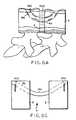
- the guide sleeve distal end 108can be disposed at other positions on the surface of the vertebrae 2 such as that illustrated in FIG. 6A .
- the surgical personnelsecure the guide sleeves 102 at each of the pivots 106. This advantageously ensures that the appropriate angles and alignment of the guide sleeves 102 with respect to the vertebrae 2 are maintained as well as locking the positioning jig 100 down on the motion segment to be fused.
- an initial through holeis formed in each vertebrae 2 by any of a number of methods, e.g. by a drill, by ablation of the material comprising the vertebrae using an energy source such as RF, ultrasonic waves, cryogenics and water jets or by any other means known to those skilled in the art and which can be adapted for use with the positioning jig 100.
- an energy sourcesuch as RF, ultrasonic waves, cryogenics and water jets or by any other means known to those skilled in the art and which can be adapted for use with the positioning jig 100.
- the following discussionis simplified to describing the method in terms of drilling the initial aperture or initial through hole 6 in the vertebrae 2. This, however, shall not be inferred as being a limitation on the method according to the present invention to only drilling.
- a fixed or flexible drill bit 150is inserted into and down each drill guide 102 so the ends thereof contact the surface of the vertebrae 2.
- the surgical personneloperate the drill bits in accordance with accepted techniques so as to create an initial through hole 6 in each of the vertebrae.
- the through holes 6 being createdare intersecting with convergent paths within the intervertebral space 4.
- the projection of the long axis for each of these through holes 6intersects so the vertex created by intersection of the long axes is located within the intervertebral space 4.
- the initial through hole 6 initially formed in each vertebrae 2has a diameter much less than that of the implant 160 that is to be used to stabilize or fuse the motion segment.
- the surgical personnelinsert a guide wire 170, such as a 0,236cm (0.093 inch) nitinol guide wire, into and down one guide sleeve 102 and through the through hole in one vertebrae 2.
- the surgical personnelcontinue to push the guide wire 170 across the intervertebral space 4 and into the through hole 6 in the other vertebrae as more clearly illustrated in FIGS. 3C-D.
- the guide wire 170is configured with a slightly curved tip.
- the guide wire 170is generally in a curved configuration when disposed in the through hole 6 of the vertebrae 2.
- a flexible/curved drill bit 152is then passed through one of the guide sleeves 102 and over the guide wire 170 so as to form a curved through aperture 6a in each of the vertebrae as shown in FIG. 3E .
- the curved or arcuate through aperture 6ais formed with a cross-section that complements the cross-sectional shape of the implant 160.
- the arcuate through apertureis sized to be slightly smaller than that of the implant 160 so there is a friction, snug or interference fit between the implant 160 and the arcuate through aperture 6a.
- the curved or arcuate through aperture 6ais formed using any of a number of other techniques as described below.
- the arcuate through aperture 6ais formed in the vertebrae 2 by using a flexible reamer 200.
- the flexible reameris run or passed over the guide wire 170 to ream or core out the arcuate through aperture 6a.
- the cancellous bone of the vertebrae 2is relatively soft so that it is possible to use a reamer to core the hole aperture.
- a curved awl or a progressively larger guide wire 170acan be used to punch a curved hole in the vertebrae.
- FIG. 4Cshows a Romano device suitable for drilling a curved bore such as that disclosed in USP 5,700,265 .
- a swing arm 830 and curved guide arm 834navigate the drill bit 840 through a defined radius of curvature.
- the discharge end of an energy sourcesuch as RF, ultrasonic, cryogenic, laser and water
- an energy sourcesuch as RF, ultrasonic, cryogenic, laser and water
- the nozzle(s) of a high pressure water sourcecan be arranged so the discharging or ice crystal water impinges on the bony material of the vertebrae 2 and the material is thereby ablated away to form the arcuate through aperture 6a.
- laser light, RF waves or ultrasonic wavescan be focused on the bony material within the vertebrae 2 to form the arcuate through aperture 6a.
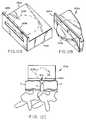
- FIG. 2Ba schematic view of an alternative positioning jig 100a that is disposed about two vertebral bodies.
- This alternative positioning jig 100ais similar to the positioning jig 100 of FIG. 2A except for the guide sleeves.
- a guide wire 170is being inserted into one of the guide sleeves 102a and is configured so that the proximal end of the guide wire 170 is arranged so as to include an impact fitting to protect the guide wire about the proximal end.
- the guide sleeves 102aare tubular members that are configured so that at least a portion 103 of each guide sleeve is arcuate.
- the arcuate portion 103 of the guide sleeve 102ais proximal the vertebral body such that one end of the arcuate portion comprises the distal end 108 of the guide sleeve that is in contact with the vertebral body 2.
- the guide sleevecan be configured so as to be substantially arcuate between the vertebral body 2 and the cross member 104.
- the arcuate shapeprovides a convenient mechanism that can simplify the above-described process for making an arcuate through hole 6a in the vertebral body 2.
- the arcuate shapealso provides a mechanism to orient the tool, device or apparatus being inserted into the guide sleeves 102a, for example the drill or high energy source for forming the initial through hole, so use of the tool etc. is more convenient to the surgical personnel performing the procedure.
- the implant 160is inserted therein so it is disposed within the through aperture 6a in one vertebrae 2, passes or extends across the intervertebral space 4 and disposed within the through aperture 6a of the other vertebrae.
- the implant 160is made from any one ore more suitable materials such as e.g. a metal such as titanium or stainless steel, bone, bone with bone morphogenic protein, carbon fiber composite, nitinol.
- the implant being inserted into the final apertureis made from one or more of a metal (e.g., titanium or stainless steel), bone, morphogenic protein (including a combination of bone and bone morphogenic protein), carbon fiber composite, nitinol or biodegradable materials such as polyactic acid or polyglycolic acids and copolymers and other derivatives thereof, or collagen and collagen coated metal or bone.
- the implantalso may comprise an in situ-formed plug where the aperture acts as a mold for an epoxy or other polymer-based system.
- the implantis curved so it generally conforms to the radius of the arcuate through apertures 6a in each vertebrae 2.
- the implant 160suitably can be provided with a circular or oval shape.
- the diameter or width of the implantcan vary over a relatively broad range and may depend on the size of the vertebrae and desired implant stiffness. More specifically, in preferred embodiments, the implant may suitably range in diameter or width from about 5 mm or as small as is mechanically sufficient, to sizes approaching that of large intramedullar rods, or about 22 mm.
- the implantshould have a diameter or width from about 7 to 12 mm, more preferably about 9 mm.
- the implantalso preferably should have an appropriate radius of curvature such that both vertebrae are engaged while staying well clear of the spinal cord. That radius preferably is about 3,81cm (1.5 inches), as referenced from the arcuate implant's inner radius.
- the implant 160is suitably a solid or hollow (e.g., tubular) member.
- the implantcan be suitably configured so as to have fenestrations 166 ( FIG. 6A ) that allow biologic elements of bone to traverse through it or across it, thereby enhancing potential for stability and for cross-segmental healing.
- the implant 160can have cutting fenestrations similar to a cheese grater, allowing fragments of bone to be pared off as the implant 160 is being inserted into the through apertures in either vertebrae.
- a fenestrated implant 160 that is hollowcan be filled with bone chips or synthetic or engineered bone healing materials, allowing for bone ingrowth, and a cheese grater type of implant with cutting fenestrations can add freshly pared fragments of bone to the packed bone chips or other materials to enhance bony ingrowth.
- the fenestrations 166can be surface dimples, sharpened edges, cutting indentations or other alterations in the exterior surface of the implant 160 to enhance or further ensure the secure fitting of the implant into the arcuate through aperture 6a as well as for facilitating bone growth.
- a threaded end 162(e.g., a female threaded end) is provided at one end of the titanium implant 160 for threaded engagement with the threaded counterpart (e.g., male counterpart) at one end 172, the distal end of the guide wire 170. This can be accomplished for example by removing at least one of the guide sleeves 102 from the entrance opening of one through aperture 6a so the threaded end 172 of the guide wire is exposed.
- the implant threaded end 162is then screwed onto the guide wire threaded end 172 and the so tethered end 162 of the implant 160 is positioned at the entrance opening of the through aperture 6a and pulled into place by pulling on, for example, the proximal end 174 of the guide wire 170.
- the distal end 108 of one guide sleeve 102remains engaged at the entrance opening for the other through aperture 6a, so as to serve as a bearing surface or brace for the guide wire 170 as it is being pulled out of this entrance opening. This is done to keep the guide wire 170 from cutting through the cancellous bone when the guide wire is under tension because of the pulling action.
- a tubular member with a rounded surfacemay be advanced over the guide wire and through the remaining guide sleeve 102, to ensure that the guide wire pulls from the appropriate angle. This technique is suitable for use with metallic and other rigid material type of implants.
- a pushing mechanismis useable for inserting or tamping the implant 160 into the arcuate through apertures 6a.
- an arcuate pushing mechanism 300is configured so as to rotate about an axis of rotation that corresponds generally to the center of the circle subscribed by the arcuate through apertures 6a.
- the arcuate pushing mechanismapplies a force to the distal end of the implant 160 so as to drive the proximal end of the implant through the arcuate through aperture 6a in one vertebrae, across the intervertebral space 4 and into the arcuate through aperture 6a of the other vertebrae 2.
- the positioning jig 100is removed except for the intervertebral spacing member 110 or bone intervertebral spacer where the intervertebral spacer 114 remains disposed in the intervertebral space 4.
- the arcuate pushing mechanism 300is attached to the end of the interconnecting member 112 by means of a jig or other member or device so the pushing mechanism can rotate about the end of the interconnecting member. In this way, the arcuate arm 302 of the pushing mechanism 300 can be advanced by having one of the surgical personnel rotating it about its axis of rotation. Alternatively, or in addition, the surgical personnel can strike one end 304 of the arm 302 with a mallet or other weighted object so as to drive the implant 160 into the through aperture 6a. For example, striking may be required near the end of the insertion process when there is maximum friction being developed on the inserted implant.
- the arm 302also may be configured with a curved support sleeve 306 in which the implant is received.
- the implant 160 and through apertures 6aare sized so that there is preferably at least a snug-fit therebetween, as an extra measure of protection, the implant 160 may be further secured in place at its ends by means of screws 400 as shown in FIG. 6C .
- the implant 160may be secured in place by a plate, screw, staple or a combination thereof.
- the implantcan be arranged so as to include a biting or expansion element(s) that can be driven out in a lateral direction so as to engage the bony structure of the vertebrae 2.
- the implant 160acan be made from nitinol.
- a nitinol implant 160ais advantageous in that a curved nitinol implant can be straightened as shown in FIG. 7B prior to insertion into the arcuate through apertures 6a.
- the straightened nitinol implant 160acan be advanced down one of the guide sleeves 102 in any of a number of ways, for example, by pushing or pulling, so it can be driven into the arcuate through apertures 6a.
- the nitinol implant 160aalso can be inserted into the arcuate through apertures 6a in any of the other fashions described above in connection with FIGS. 5A-B.
- a sharp edge of the nitinol implantcan be used like a reamer or awl to thereby enlarge the initial through hole 6 as the implant is being inserted or driven into the initial though aperture. This avoids the intermediate step of drilling or otherwise forming the arcuate through aperture 6a before insertion of the implant.
- FIG. 7Cdepicts an illustrative device 400 for inserting a nitinol implant 160a, which device includes a guide tube 402 and a pusher 404.
- the distal end 408 of the guide tube 402, similar to the positioning jig guide sleeve distal end 108is preferably configured so as to be capable of releasably mating with a surface, or portion thereof, of the vertebrae 2 where the entrance of the arcuate through aperture 6a is located.
- the guide tube distal end 408is configured with a cut out so as to receive a corner of the vertebrae 2 therein.
- the distal end 408is disposed on the vertebrae so that the lumen therein is aligned with the arcuate through aperture 6a.
- the straightened nitinol implant 160ais inserted into the guide tube 402 along with the pusher 404 such that the distal end of the pusher is in contact with the proximal end of the nitinol implant.
- the pusher distal end 408mates with the implant proximal end so as to maintain the orientation and direction of the nitinol implant 160a within the guide tube 402 so that it curves in the proper direction when it exits the guide tube.
- the orientation of the nitinol implant 160a within the guide tube 402is maintained with a flat side or with a key and notch type of arrangement.
- the pusher 404includes a stop 406 to limit the travel of the pusher within the guide tube 402. This in turn limits the amount of travel by the nitinol implant 160a so as to assure that the implant remains buried within the vertebrae and not exposed above the surface thereof.
- the placement of the implant according to the systems of the present inventionis advantageous in that the inserted implant resides completely within the vertebrae and, thus, within the spine, with no protrusion as compared with prior art devices.
- the implant and its placementprovide a configuration which allows for some compression and cantilever force, but deters rotation and sheer. Additionally, in the present device, the moment arm is more centrally located within the spine as compared to prior devices. This central location also provides better stability in the face of torsion as compared to prior art devices.
- an arcuate implant within the arcuate through apertures as described hereinis particularly advantageous because the implant is buried to avoid contact with neurovascular structures.
- the placementprovides load sharing and thus provides a better healing bio-mechanical environment and also provides a more advantageous fixation to avoid mechanically sub-optimal stresses.
- this methodallows securement and avoids displacement of a spinal fusion or disk replacement device without modification or damage to the vertebrae's load bearing surface. Rather, one or two holes placed in or around the center of a vertebrae can be sufficient.
- the method and positioning jig 100also are advantageous in that the jig can be adapted for use in minimally invasive procedures.
- the capability to position implants in accordance with the methods described hereinenables avoiding blood vessel injury, erosion into organs and damage to adjacent nerves. This provides a significant advantage over presently existing technologies for disorders of the spine including fractures, arthritis, deformity, infections, tumor and mechanical spinal disorders.
- the above described methodcan be further adapted so as to be used to secure an intravertebral prosthetic device 500 (i.e., artificial disc) such as that shown in FIG. 6A .
- the implantis made partly or wholly from a flexible material such as silicon, elastomeric polymers, polyurethances and copolymers thereof, hydrogels, collagen, bioabsorbables, compositions, or a metallic spring or coil, so as to allow continual mobility between the vertebral bodies.
- One or more arcuate implantsare provided which pass through a partial or complete hole in the prosthesis. This effectively prevents the prosthesis from becoming dislodged as well as maintaining its location and orientation within the disc space.
- FIGS. 17A-Cexemplary arcuate implants 160b-d for use in securing the intravertebral prosthetic device 500 within the bones of the spine.
- an arcuate implant 160bhaving a first section 163 disposed between two end or second sections 165 that mechanically engage the first section.
- the first section 163is made up of a compressible material and the second sections 165 are made up of a material(s), such as metals and bone, that is conducive to the attachment of the second sections to the bone thereby securing the implant 160b.
- the implant 160ccan comprise a first section 163 that is bonded or otherwise mechanically secured to the second sections 165.
- the implants 160b,c of either FIGS. 17A,Bextends through an aperture or hole in the prosthetic device 500 and into the vertebral bodies adjacent to the prosthetic device similarly to that illustrated in FIG. 16A. Additionally, the first section 163 of either of the two implants 160b,c is arranged so as to extend through the prosthetic device 500. See also the discussion above for FIG. 16A for other aspects of securing the prosthetic device (e.g., one or more apertures in the prosthetic) and materials for the implant.
- the above described methodalso can be further adapted so as to be used to secure an intravertebral prosthetic device 500 (i.e., artificial disc) according to another technique such as that shown in FIG. 6B using an implant, such as the exemplary implant 160d shown in FIG. 17C .
- an intravertebral prosthetic device 500i.e., artificial disc
- an implantsuch as the exemplary implant 160d shown in FIG. 17C .
- any of the mechanisms and methods described hereinare used to form at least an aperture 6, preferably an arcuate through aperture, in one adjacent vertebral body 2a.
- the aperture forming mechanism or methodalso forms another aperture 6' in the other adjacent vertebral body 2b.
- This another aperture 6' in the other vertebral body 2bis not a through aperture but rather only extends only into a portion of the other vertebral body.
- the prosthetic device 500is disposed in the disc space or intervertebral space 4.
- the implant 160dis then pressed into and through the aperture 6, through the prosthetic device 500 and intervertebral space 4 and into the aperture 6' of the other adjacent vertebral body 2b.
- the exemplary arcuate implant 160d shown in FIG. 17Cincludes a first section 163 and a single second section 165 that mechanically engages the first section as shown in FIG. 17A or is bonded or other wise mechanically secured to the first section as shown in FIG. 17B .
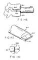
- FIG. 9shows a method for inserting an implant 600 according to a second aspect.
- a final through aperture 604is formed in each of the vertebrae in accordance with above described techniques such as by drilling. Except that the through aperture 604 that receives the implant can be straight as shown in FIG. 9 or can be arcuate as shown in any of FIGS. 3-6 . As such, reference should be made to the foregoing discussion for further details regarding the formation of the final through aperture 604.
- the implantis in two sections 602a,b.
- the proximal ends 608 of the two sections 602a,bare particularly configured so they can be mated to each other and interlocked to each other by means of an interference fit, a nut and bolt, a screw or a pin 606.
- one section 602ais inserted into the through aperture 604 in one vertebrae 2 and the second section 602b is inserted into the through aperture 604 of the other vertebrae.
- the two sections 602a,bare inserted into their respective through apertures until the proximal ends 608 thereof are mated to each other.
- the pin 606 or other securing mechanismis then used to interlock the proximal ends and thus form a rigid implant.
- the sectionsare illustrated as being straight, the sections can be arcuate so as to form an interlocking rod when assembled.
- FIG. 10shows a method for inserting an implant 600 according to a third aspect.
- the apertures 702 in each vertebrae 2are formed so they extend from the vertebral space 4 outwards, penetrating into the cancellous bone.
- the apertures 704 formed in the vertebraeneed not be through apertures.
- the implant 600is like that described above for the second aspect except that it is inverted from that shown in FIG. 9 .
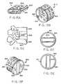
- FIGS. 11A,BThere is respectively shown in FIGS. 11A,B a cutter bracket system 1100 and a curved bit or drill system 1120, the curved drill system being for use with such a cutter bracket system.
- the cutter bracket system 1100 and curved drill system 1120comprises another embodiment for forming arcuate apertures 6a ( FIG. 6A ) in each of the adjacent vertebral bodies 2.
- the cutter bracket systemincludes temporary vertebral screws 1102, pivot brackets 1104 and a pivot arm 1106.
- there is two temporary vertebral screws 1102that are each secured to the adjacent vertebral body 2 that is to be fused, however, this shall not be construed as a limitation on the number of intervertebral screws.
- the pivot brackets 1104which locate the pivot point 1108 with respect to the adjacent vertebral bodies 2 and maintian the pivot point in this orientation.
- the pivot arm 1106is rotatably mounted to the pivot brackets 1104 using any of a number of mechanisms or techniques known in the art so that the pivot arm pivots or rotates about the pivot point 1108.
- the temporary vertebral screws 1102, the pivot brackets 1104 and the pivot arm 1106are made from stainless steel although other materials are contemplated.
- the drill system illustrated in FIG. 11Bincludes a curved cannula 1122, a flexible cable 1124, a cutting head or burr 1126 and a motor 1130.
- the flexible cable 1124is rotatably disposed with the curved cannula 1122.
- One end of the flexible cable 1124is attached to the cutting burr 1112 and the other end of the flexible cable 1124 is attached to the motor 1130, whereby the motor drives the cutting burr so it to rotates in the desired manner.
- the motor 1130also is mounted to an end of the curved cannula 1122.
- the curved cannula 1122is made from stainless steel and the flexible cable 1124 is a flexible, teflon coated stainless steel cable, the cutting burr 1126 is made from stainless steel, although other materials can be used.
- the motor 1130includes any of a number of devices known in the art that develop or provide a rotary output which can be used to rotate the flexible cable 1124, such devices include, but are not limited to, electric or pneumatic drills, DC/AC electric motors, or , pneumatic, air driven rotary motors.
- the drill system 1120can further include a coupling member, as is known in the art, that operably and rotatably interconnects the flexible cable 1124 and the motor 1130 such that the motor is located remote from the curved cannula 1122.
- a coupling memberas is known in the art, that operably and rotatably interconnects the flexible cable 1124 and the motor 1130 such that the motor is located remote from the curved cannula 1122.
- the drill system 1120is mounted or attached to the pivot arm 1106, distal from the pivot point 1108, by means of a connector 1128 on the curved cannula 1122.
- the connector 1128 and the corresponding feature on the pivot arm 1106comprises any of a number of mechanisms or devices known in the art (e.g., clamp type mechanism) by which the curved cannula can be removably secured to the pivot arm so there is essentially no relative movement therebetween.
- the curved cannula 1122is secured proximal to or at the distal end of the pivot arm. In this way when the drill system 1120 is secured to the cutter bracket pivot arm 1106 and the cutter bracket pivot arm 1106 is rotated about the pivot point 1108, the pivot arm guides the curved drill system, in particular the cutting burr 1126 on a well-defined circular path.
- the cutter bracket system 1110is temporarily secured to the adjacent vertebral bodies 2 to be fused by the temporary vertebral screws 1102.
- the cutter bracket system 1110is secured to the vertebral bodies 2 so that the pivot point 1108 is positioned so as to be spaced from a surface of the vertebral bodies and so as to be between the adjacent vertebral bodies, more particularly at about the midpoint of the intervertebral space 4.
- the curved drill system 1120is mounted to the pivot arm as described above.
- the pivot arm 1106is then rotated in one direction, for example a clockwise direction, about the pivot point 1108.
- the cutting burr 1126is operated so the drill system 1120 drills an arcuate hole in the vertebral body 2 on one side of the pivot point.
- the curved drillis then remounted so the cutting burr 1126 is on the other side of the pivot point 1108 and the pivot arm is rotated in a counter clockwise direction so the drill system 1120 drills an arcuate hole in the vertebral body 2 on the other side of the pivot point 1108.
- the arcuate holeis completely formed when the pivot arm 1106 bottoms out or contacts the vertebrae being drilled.
- the curved drill system 1120is dismounted from the pivot arm 1106 and the cutter bracket system 110 is disconnected from the adjacent vertebral bodies 2.
- the cutter bracket system 110is disconnected from the adjacent vertebral bodies 2.
- two matched arcuate holesare formed in the adjacent vertebral bodies 2 that are sized and configured to receive an arcuate implant being inserted therein. Reference shall be made to the foregoing discussion for further details regarding such an arcuate implant or fixation member.
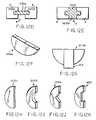
- a slotis cut in each of the adjacent vertebral bodies and a biscuit implant is inserted into the slots so as to also bridge across the intervertebral space 4.
- the slotsare simultaneously cut in the vertebral bodies so a common channel is formed therein.
- a cutting device 1200having a cutting implement, for example a circular blade 1206 that is rotated by a motor (not shown).
- the cutting device 1200also is configured so the blade 1206 is moveable between a first position, where the blade is disposed within the device housing 1202 ( FIG.
- the exterior side 1204 from which the blade 1206 extendsis configurable so that in one position the exterior side is substantially parallel to a tangent at the midpoint of the blade and further includes indicia 1208 representative of the mid-point of the blade.
- the cutting device 1200is positioned so the device housing exterior side 1204 abuts or is adjacent to the vertebral bodies 2 and so the indicia 1208 representative of the blade midpoint is pointing towards the intervertebral space 4, preferably about a midpoint between the adjacent vertebral bodies.
- the rotating circular blade 1206is then moved from the first to the second position so as to simultaneously cut an arcuate slot in each of the adjacent vertebral bodies 2. After cutting the slot, the circular blade 1206 is returned to the first position with the device housing 1202 and the cutting device 1200 is removed from the vertebral bodies.
- a biscuit implant 1210asuch as that shown in FIG. 12F , is inserted into the arcuate slot in each of the adjacent vertebral bodies and so as to bridge therebetween.
- the biscuit implant 120ais secured in the arcuate slot 1209 using any of the methods described herein for the other implants thereby fusing and stabilizing the adjacent vertebral bodies.
- a biscuit implant 1210bsuch as that shown in FIG. 12G , is configured so as to include a spacer element 1212.
- the biscuit implantin addition to the exemplary biscuits implants 1210a,b illustrated in FIGS. 12F-G , the biscuit implant, whether it is configured with or without a spacer element 1212, can be formed in any of a number of geometric shapes that are otherwise consistent with the intended use. This includes the biscuit implants 1210c-f shown in FIGS. 12H-K . Reference shall be made to the foregoing discussion regarding the other implants or fixation members as to the materials and other features (e.g., fenestartions) which apply equally for a biscuit implant.
- FIGS. 13A-13Fan implant system according to these systems and methods.
- FIG. 13Ashows an embodiment of the inner implant 800 adapted for inspection within the outer implant 810 shown in FIG. 13B .
- the inner implant 800 in FIG. 13Ais shown as a substantially hollow device equipped with a fenestrated wall 802.
- the inner implant 800bears on a lateral surface 814 a key slat 804 adapted to secure and orient the inner implant 800 within the outer implant 810 shown in FIG. 13B .
- the key slat 804 in the illustrated embodimentcan slide into a key groove 808 situated on the inner aspect 818 of the outer implant 810.
- FIG. 13Ashows an embodiment of the inner implant 800 adapted for inspection within the outer implant 810 shown in FIG. 13B .
- the inner implant 800 in FIG. 13Ais shown as a substantially hollow device equipped with a fenestrated wall 802.
- the inner implant 800bears on a lateral surface 814 a key slat 804
- the outer implantis equipped with a trough and trough slit and a fenestrated wall 812 as shown in FIG. 13D .
- the devices shown in these figurescan be fabricated from a plurality of materials including both absorbable and non-absorbable biocompatible materials. Materials may include metallics, ceramics, plastics, polymers, biological materials and materials produced by biotechnology. A variety of suitable materials will be readily envisioned by those of ordinary skill in the art for use in the system .
- FIG. 13Cshows a lateral view of two vertebral bodies 820 and 822 showing the general position of the implant system 824.
- the edge of the outer implant 828is shown imbedded and buried in the vertebral bodies 820 and 822.
- the edge of the inner implant 830is shown positioned within the intervertebral disc space 834.
- a set of bone cuts 832 and 836are made at the buried end of the implant system 824.
- FIG. 13Dshows an anterior view of the outer implant 838 positioned with the inner implant 840 secured within it .
- FIG. 13Eshows an anterior view of the inner implant 844 secured within the outer implant 842 .
- the entire implant system 845is shown in the rotated 90 degrees relative to the angle at which the implant system 848 is inserted into the vertebral bodies and disc space (not shown).
- the inner implant 844 in this viewassumes a vertical position within the implant system 848, and the outer implant is rotated 90 degrees to effect this repositioning.
- FIG. 13Fshows in more detail a perspective view of an embodiment of the implant system 850.
- the inner implant 854is shown positioned within the outer implant 858, the entire implant system 850 being turned vertically.
- two bone sections 860 contained between the inner implant 854 and the outer implant 858are turned to a vertical position. These bone sections 860 thus provide structural stability to the system 850 and to a spine unit (not shown).
- the vertical repositioningplaces cortical bone in a more supportive position.
- the outer implant 858is shown with a fenestrated wall 852 for facilitating bony ingrowth. These fenestrations are larger at the upper and lower confines of the repositioned bone graft sites to enhance fusion.
- the inner implant 854is shown with a hollow interior section 862 available for containing a solid displacing shim and bone chips, bone matrices, growth factors or other agents for encouraging or facilitating bony ingrowth and enhancing stable positioning of the verticalized cortical bone sections.
- Other substances useful to the healing processcan be provided within this interior section 862. For example, antibiotics can be placed in this interior section 862 in a suitable vehicle. Other substances and matrices can be envisioned by practitioners of those arts.
- the outer implant 838,858is configured so as to include an axially extending slot or slit 841,864 that is arranged and configured so as to permit adjustment of the diameter of the outer implant, for example to permit the outer implant to be expanded outwardly.
- the structure forming the adjustment slit 841,864includes any of a number of configurations, structures or arrangements that permit relative movement between the sides of the outer implant on either side of the adjustment slit.
- Such structures, arrangements and configurationsinclude, but are not limited to an axially extending through aperture or an axially extending ship-lap type of joint where portions of the axially extending sides slidably overlap each other.
- FIGS. 14A - 14Cthere is generally down in FIGS. 14A - 14C , an inner tool 900 to be used.
- FIG. 14Ashows the inner tool 900 positioned with the intervertebral disc space 906.
- the inner tool 900bears on its distal end, a shorter disc end 902 that is adapted for insertion within the intervertebral disc space 906 to allow for cutting a segment of the vertebral bodies 904 and 908 above and below it.
- FIG. 14Bshows a perspective view of an inner tool 910.
- the distal end 912 thereofis adapted for cutting the cortical vertebral end plates that it abuts.
- FIG. 14Cshows in more detail an embodiment of the cutting mechanism bone by the inner tool 916.
- a cutting end 914 at the distal end of the tool 916bears a set of stop cut blades shown here in the retracted position 920 and in the extended position 918. Directing the blades from the retracted position 920 to the extended position 918 effects a cut in the adjacent bone (vertebral endplate, not shown). While the depicted embodiment of a tool can be advantageously employed in conjunction with the implant system according to these systems and methods other tools and devices can be envisioned by skilled practitioners of these arts for cutting bone and for positioning an implant system.
- Figure 15shows a lateral view of an embodiment of the tool system 1000 positioned in relation to the vertebral bodies 1014 and 1018.
- an inner tool 1002is shown with its distal end positioned between the vertebral bodies 1014 and 1018.
- An outer tool 1004is shown in two positions, a position 1008 before driving it into the vertebral bodies 1014 and 1018 and a position 1020 after driving it into the vertebral bodies 1014 and 1018.
- a blade 1022 of the outer tool 1004is shown positioned at the anterior aspect of the vertebral body 1014 before the outer tool 1004 is driven into the vertebral body 1014.
- the blade 1024is shown imbedded in the vertebral body 1018, having cut it perpendicular to its anterior face.
- the inner tool 1002can make bone cuts 1012 at right angles to the blade 1024 of the outer tool 1004, thereby creating a bone slab 1010 that can be repositioned.
- This bone slab 1010 (section)can be cut so as to allow for anterior vertebral distraction by making these slabs oblong rather than circular.
- FIG. 16shows a bone-to-bone application using techniques not in accordance with the present invention.
Landscapes
- Health & Medical Sciences (AREA)
- Orthopedic Medicine & Surgery (AREA)
- Life Sciences & Earth Sciences (AREA)
- Surgery (AREA)
- Engineering & Computer Science (AREA)
- Biomedical Technology (AREA)
- Animal Behavior & Ethology (AREA)
- Veterinary Medicine (AREA)
- Public Health (AREA)
- Heart & Thoracic Surgery (AREA)
- General Health & Medical Sciences (AREA)
- Molecular Biology (AREA)
- Medical Informatics (AREA)
- Nuclear Medicine, Radiotherapy & Molecular Imaging (AREA)
- Neurology (AREA)
- Oral & Maxillofacial Surgery (AREA)
- Dentistry (AREA)
- Transplantation (AREA)
- Cardiology (AREA)
- Vascular Medicine (AREA)
- Physical Education & Sports Medicine (AREA)
- Prostheses (AREA)
Description
- The present invention generally relates to systems and apparatuses adapted for fixing the bones of the spine, and to systems and apparatuses adapted for securing a prosthetic device within the bones of the spine.
- Fixation or fusion of vertebral columns with bone or material, rods or plates is a common, long practiced surgical method for treating a variety of conditions. Many of the existing procedures involve the use of components that protrude outwardly, which may contact and damage a body part, such as the aorta, the vena cava, the sympathetic nerves, the lungs, the esophagus, the intestine and the ureter. Also, many constructions involve components that may loosen and cause undesirable problems, often necessitating further surgical intervention. Additionally, limiting the success of these procedures are the bio-mechanical features of the spine itself, whose structure must simultaneously provide support to regions of the body, protect the vertebral nervous system and permit motion in multiple planes.
- As indicated above, spinal surgery for spine fusion generally involves using implants and instrumentation to provide support to the affected area of the spine while allowing the bones thereof to fuse. The technology initially evolved using bone chips around and on top of an area of the spine that had been roughened to simulate a fracture in its consistency. The area, having encountered the bone chips, would then proceed to heal like a fracture, incorporating the bone chips. However, surgical procedures dealing with the spine present notable challenges. For example, bioengineers have been required to identify the various elements of the complex motions that the spine performs, and the components of the complex forces it bears. This complexity has made it difficult to achieve adequate stability and effective healing in surgical procedures directed to the spine.
- One surgical technique provided by Cloward, involves cutting a dowel type hole with a saw across or through the moveable intervertebral disc and replacing it with a bone graft that was harvested from the hip bone. This procedure limits motion and mobility and results in a fusion of the adjacent vertebral bodies. However, as a result of the complex motions of the spine, it is often difficult to secure the dowel from displacing. Further, it has become apparent over time, however, that this particular technique does not always yield a secure fusion.
- Other techniques have been developed that involve the placement of various hardware elements, including rods and hooks, rods and screws and plates and screws. The dowel technique also has advanced over the past five years or so, with dowels being fabricated from cadaver bone or metals such as titanium or stainless steel. These techniques, whether using hardware, dowels or some combination thereof, have a common goal to enhance stability by diminishing movement, thereby resulting in or enhancing the potential of a fusion of adjacent vertebral bones. For example, in one of these other techniques, the disc is removed and adjacent vertebrae are positioned in a stable position by placing a plate against and traversing them, which plate is secured or anchored to each by means of screws.
- In another procedure, cages in the form of two parallel circular or rectangular devices are made out of a material such as titanium or stainless steel and these devices are fenestrated. Bone is packed in the center of the devices that will heal to adjacent bone through each fenestration. In this procedure, the disc space is distracted so all ligamentous structures are taut and the bones are held in their normal maximal position of distraction. Because the cages are implanted in spongy bone, they are more likely to collapse the surrounding bone, thus resulting in loss of distraction and subsequently cage dislodgment.
U.S. Patent 5,591,235 reports a certain spinal fixation device and technique for stabilizing vertebrae. In this technique, a hollow screw is inserted into a hole, preferably a hole saw recess, in each adjoining vertebrae. A channel is cut into the vertebrae, which is lined up with corresponding axial slots in the screw. A rod is inserted into the channel and so as to pass through the axial slots in the screw. The rod is secured to each of the screws by means of a locking cap. The rod also is arranged so as to provide a bridge between the hollow screws in the adjoining vertebrae. Certain disadvantages have been surmised using such a device and technique. For example, it has become apparent that the trough in the vertebral bodies destabilizes some of the cortex of the vertebrae body wall, which is the strongest component.- The features of the preamble of claim 1 are known from the document
US-A-47 90303 . - In addition to fixation or fusion of vertebral columns, the prior art also describes methods or other spinal repair procedures, such as discectomy wherein an artificial disc or prosthetic device is placed within the vertebrae of the spine. For such prior art methods and related devices, there have been short comings such as having difficulty in securing the prostheses within the vertebral space or resulting in significant modification or damage to the load bearing surfaces of the vertebrae in an effort to secure the prosthesis.
- Thus, it would be desirable to provide a new apparatus, system and methods for spinal fixation that enhances healing of the bone while providing structural support to the spine. It would be particularly desirable to provide such an apparatus, system and method that would involve the use of open surgical or minimally invasive surgical techniques as well as a technique in which the implant burrows in the bone spine, traverses across the disk space, and ends in an adjacent or neighboring vertebrae or vertebras, providing limited or no protrusions. It also would be desirable to provide such an apparatus, system and method where the implant is retained within the bone without requiring contour-varying external vertebral wall fixation as compared to conventional devices, as such a device would avoid many of the problems associated with conventional devices such as blood vessel injury, erosion into organs, as well as placement near nerves. Additionally, it would be desirable to provide such an apparatus, system and method where the implant is retained within the bone and is utilized to secure an artificial prosthesis for example within the vertebral bodies. Such securing is accomplished with or without the use of the annulus, and without insult to portions of the vertebral surfaces bearing significant loading.
- I have now found new apparatus for fixing adjacent vertebrate of a spine. The apparatus of the invention utilize a new implant member, which is arcuate, and avoids the associated problems with prior cage or straight rod and screw systems. It is within the scope of the present invention for the implant member to have any geometric shape or configuration consistent with the intended use.
- The present invention is defined by the features of claim 1.
- Methods for stabilizing adjacent vertebrae of the spine, include the steps of providing a positioning apparatus including two guide sleeves, each guide sleeve having a long axis and locating the two guide sleeves with respect to the adjacent vertebrae such that a vertex formed by the long axis of each guide sleeve is located in the intervertebral space for the adjacent vertebrae. The method further includes forming an aperture in each of the adjacent vertebrae using the guide sleeves and inserting an implant into the apertures formed in each of the adjacent vertebrae so that the implant extends between the adjacent vertebrae and through the intervertebral space.
- Preferably, the aperture formed in the vertebrae is arcuate and the implant being inserted also is arcuate. The arcuate aperture in each vertebrate can be suitably formed by drilling or other ablation. More particularly, an initial aperture can be drilled in each of the adjacent vertebrae to create intersecting apertures with convergent paths within the intervertebral space; and the initial aperture then enlarged to receive the implant. That enlarging of the initial aperture can be suitably performed by a variety of procedures, e.g. by using a drill bit, a reamer, an awl, impaction drill, shape memory coring device, or curved coring device, or the like.
- The step of forming an aperture also can further include inserting a guide member, after drilling of the initial aperture, into one of the guide sleeves, down through the initial aperture in one adjacent vertebrae, through the intervertebral space and into the initial aperture in the other adjacent vertebrae; and advancing an aperture enlarging device over the guide member so as to enlarge the initial aperture. In this case, the aperture enlarging device is suitably a curved reamer or a curved drill bit, and the curved reamer or the curved drill bit is advanced over the guide member so as to form an arcuate aperture in each of the adjacent vertebrae. It also should be appreciated that multiple vertebral holes can be created using the same methods as disclosed herein. In that manner, multiple arcuate implants can be placed, e.g. if greater mechanical stability is considered desirable.
- The positioning apparatus can further include a cross member and an intervertebral spacer, preferably where the guide sleeves are pivotally mounted to the cross member and the intervertebral spacer is spaced from the cross member and interconnected thereto at about a mid point between the pivot points for the guide sleeves. In this case, the stabilizing method can further include locating the intervertebral spacer in the intervertebral space between the adjacent vertebrae; and maintaining alignment of the guide sleeves with respect to the adjacent vertebrae so that a consistent angle is maintained between the guide sleeve and the vertebrae during at least a portion of said forming of the aperture. The intervertebral spacer also can be configured so as to provide protection to the spine during the drilling when disposed in the intervertebral space.
- In an alternative embodiment, the positioning system being provided includes a cutter bracket system and a curved drilling sub-system affixed thereto. The cutter bracket system includes a pivot arm whose pivot point is disposed between the adjacent vertebrae opposite the intervertebral space. More particularly, the pivot point is at about the midpoint between the adjacent vertebrae. The curved drilling sub-system is affixed to the pivot arm such that as the pivot arm rotates about the pivot point the curved drill sub-system follows an established cutting path. In a more specific embodiment, the drilling sub-system is affixed proximal or at the distal end of the pivot arm. The positioning apparatus according to the alternative embodiment can further include a mechanism that temporarily secures the cutter bracket system to the adjacent vertebra to be fused and which positions and maintains the pivot point at the desired location. Also, the curved drill subsystem can include a curved cannula, a flexible member running through the curved cannula and a cutting burr secured to an end of the flexible member.
- As to the step of forming an aperture using a positioning system according to the alternative embodiment, this step includes rotating the pivot arm in one direction about the pivot point so the curved drilling sub-system forms an aperture in one of the adjacent vertebrae and rotating the pivot arm in another direction about the pivot point so as to form an aperture in the other of the adjacent vertebrae. In a more specific embodiment, the step of forming further includes remounting the curved drilling subsystem to the pivot arm before rotating the pivot arm in the another direction so a cutting element of the curved drilling subsystem is aligned for the direction of movement.
- As to inserting the implant, the method step includes successively drawing a portion of the implant through the arcuate aperture in one adjacent vertebrae, through the intervertebral space and into the arcuate aperture of the other adjacent vertebrae. In a specific embodiment, the step of inserting includes securing one end of a guide wire to an end of the implant; passing a free end of the guide wire through the arcuate aperture in one of the adjacent vertebrae, through the intravertebral space and through the arcuate aperture in the other adjacent vertebrae; and pulling on the guide wire free end to thereby successively draw the portion of the implant.
- In another embodiment, the step of inserting includes inserting a beginning end of the implant into an entrance opening of one of the adjacent vertebrae; applying a force to the portion of the implant extending from the entrance opening so as to drive the implant beginning end though the arcuate aperture in the aperture of said one of the adjacent vertebrae, through the intervertebral space and into the arcuate aperture in the other of the adjacent vertebrae.
- The implant being inserted into the final aperture is made from one or more of a metal (e.g., titanium or stainless steel), bone, morphogenic protein (including a combination of bone and bone morphogenic protein), carbon fiber composite, nitinol or biodegradable materials such as polyactic acid or polyglycolic acids and copolymers and other derviatives thereof, or collagen and collagen coated metal or bone. The implant also may comprise an in situ-formed plug where the aperture acts as a mold for an epoxy or other polymer-based system. Also, the implant can be solid or hollow and arranged with or without ingrowth fenestrations and screw holes for post-insertion securement. The implant also can be configured so the implant includes a first and a second section, where a distal end of each of the first and second sections is configured so as to be capable of being secured together. For such an implant, the method further includes the steps of inserting the first section into the aperture in one of the adjacent vertebrae so that the distal end therefore is disposed in the intervertebral space; inserting the implant second section into the aperture in one of the adjacent vertebrae so that the distal end therefore is disposed in the intervertebral space; and securing the distal ends of the first and second sections together. The implant sections being inserted can be arcuate with a radius substantially the same as the arcuate aperture or substantially straight. In particular embodiments, the distal ends of the implant sections are secured to each other by e.g. a nut, bolt, pin, expansion or press-fit device, or interlocking member on the end of each section. Other stabilization methods also can be employed. For instance, a plate can be applied to the vertrebrae surface with attachments at each end of the tunnel traversed by an implant in accordance with the invention.
- Another method for stabilizing adjacent vertebrae of the spine includes the step of forming a common channel in and between the adjacent vertebrae and inserting a biscuit implant in the common channel so as to bridge between the adjacent vertebrae. In more specific embodiments, the step of forming includes simultaneously cutting a slot, preferably an arcuate slot, in each of the adjacent vertebrae so as to form the common channel and providing a device configured so as to be capable of simultaneously cutting the slot in each of the adjacent vertebrae. Also for said step of inserting, the biscuit implant can be further configured so as to include a spacer element that is received in the intervertebral space between the adjacent vertebrae when the biscuit is disposed in the common channel.
- In another alternative aspect, a diskectomy can be performed and a stabilizing wedge (inner) implant inserted between the vertebrae. The wedge (inner tool) establishes lordosis, provides a construction reference, and carries on it the stabilizing wedge implant. Retracted stop-cut blades on the inner tool are then engaged, cutting into the vertebrae in the vertical plane. A hole saw can be used to create a circular cut in the vertebrae to facilitate insertion of the outer implant. Once the cut is complete, the bone harvested in the tubular cutter can be manipulated into the implant. A circular (outer) implant is then inserted over the inner tool. The outer tool then references the position of the inner tool and guides the implant into place. After the two implants nest together along a key and groove, the outer tool is removed. A fenestrated circular member then replaces the outer cutting tool and the inner tool is rotated about 90 degrees and then removed. Working together, the two rotated implants capture the vertebral body sections, which are now rotated about 90 degrees and through their many holes, provide blood exchange with the adjacent bone to accomplish fusion.
- Also featured is a system and apparatus embodying the described methods or techniques for internal fixation of the spine.
- Other aspects and embodiments of the invention are discussed below.
FIG. 1A is a schematic view of a positioning jig ;FIG. 1B is a front view of the intervertebral spacing member ofFIG. 1A ;FIG. 2A is a schematic view of the positioning jig ofFIG. 1A disposed about two vertebral bodies;FIG. 2B is a schematic view of an alternative positioning jig disposed about two vertebral bodies;FIGS. 3A-E are schematic views that illustrate the various steps of the process to form a hole in each vertebral body for implanting a fixating member therein;FIGS. 4A and 4B are schematic views that illustrate alternate ways of making a hole in each vertebral body;FIG. 4C is a plan view of a Romano device for making a curved hole. Shown is one of the two opposed curved cutter guides and a flexible cable having a cutting bit attached to one end;FIG. 5A is a schematic view of one device for implanting the fixating member;FIG. 5B is a schematic view of alternate device for implanting the fixating member;FIG. 6A is a schematic view of the vertebral bodies illustrating the implantation of the fixating member according to the present invention in the holes;FIG. 6B is a schematic view of the vertebral bodies illustrating another form of implantation of the fixating member in the holes particularly for securing an intravertebral prosthetic device;FIG. 6C is a schematic view of the vertebral bodies to illustrate securing of the fixating member;FIGS. 7A-C are schematic views of the implantation of a fixating member made from nitinol;FIGS. 8A-B are exemplary cross sectional views of a guide sleeve including a mechanical guide to guide the nitinol fixating member during insertion;FIG. 9 is a schematic view of the vertebral bodies with a fixating member according to a second aspect;FIG. 10 is a schematic view of the vertebral bodies with a fixating member according to a third aspect;FIG. 11A is a schematic view of a cutter bracket system ;FIG. 11B is a schematic view of a curved drill used with the cutter bracket system ofFIG. 11A ;FIG. 12A is a perspective view of a common channel cutting device ;FIG. 12B is a perspective view of a portion of the channel cutting device ofFIG. 12A with the cutting implement extended;FIG. 12C is a schematic view of the channel cutting device ofFIG. 12A disposed on two vertebral bodies;FIG. 12D is a schematic view of the two vertebral bodies to illustrate the implantation of the biscuit implant in the cut common channel;FIG. 12E is another view of the two vertebral bodies to illustrate the implantation of the biscuit implant including a spacing element in the cut common channel;FIG. 12F is a perspective view of the biscuit implant ofFIG. 12D ;FIG. 12G is a side view of the biscuit implant with spacing element ofFIG. 12E ;FIGS. 12H-K are perspective views of various exemplary biscuit implants ;FIGS. 13A-13F illustrate an alternative implant system; whereFIG. 13A is an isometric view of an inner implant,FIG. 13B is an isometric view of an outer implant,FIG. 13C is a lateral view showing a preferred positioning of the implant system,FIG. 13D is an anterior view of the outer implant within which the inner implant is secured,FIG. 13F is an anterior view of the outer and inner implant after rotation, andFIG. 13F is a perspective view of an embodiment of the implant system;FIG. 14A is a schematic view of an inner tool positioned within the intervertebral disk space;FIG. 14B is an isomeric view of the inner tool;FIG. 14C is a cross-sectional view of the inner tool, with retracted and extended stop-cut blades;FIG. 15 is a schematic view of the inner and outer tool system positioned in relation to the vertebral bodies;FIG. 16 is a schematic view showing bone-to-bone with no gap application; andFIGS. 17A-C are schematic views of exemplary implants useable for securing a prosthetic device.- Referring now to the various figures of the drawing wherein like reference characters refer to like parts, there is shown in
FIGS. 1-2 various schematic views of a drill guide orpositioning jig 100 that positions or aligns the drill bits before making the holes in each of thevertebral bodies 2. Thepositioning jig 100 includes twoguide sleeves 102, across member 104 and anintervertebral spacing member 110. Eachguide sleeve 102 preferably is a hollow tubular member having a lumen or passage therein for receiving and guiding the means for forming at least the initial aperture in the adjacent vertebrae such as a drill bit 150 (FIG. 3B ). As indicated elsewhere herein, the aperture may be formed using other techniques such as the ablation of bone by an energy source, e.g., high-pressure water, high-pressure air, ultrasound, or a laser. As such, it shall be understood that the internal sizing and configuration of the guide sleeves is established to accommodate the particular mechanism used for forming the aperture. - The
guide sleeves 102 are mounted to thecross member 104 in such a way that they are each pivotal about the cross member and so each can be secured or locked in a particular angular position with respect to the cross member. Although a single mounting/pivot point 106 is illustrated, thecross member 104 and eachguide sleeve 102 can be configured with a plurality or more of such pivot/ mounting points. In an exemplary embodiment, thecross member 104 and guidesleeves 102 are constructed from stainless steel; and each guide sleeve is pivotally secured to the cross member by screws. - The
distal end 108 of eachguide sleeve 102 is configured for mechanically engaging a surface, edge, comer or other surface artifact or feature of thevertebral body 2. In an exemplary embodiment, and as more clearly illustrated inFIG. 3A , the guide sleevedistal end 108 is configured or arranged with a cutout that is designed to accept the corner of thevertebral body 2. Additionally, the cutout area and thus thedistal end 108 also are configured with a plurality or more ofteeth 107. Theteeth 107 are configured and arranged so the teeth bite into the bony surface of the vertebral body when the corner of thevertebral body 2 is received within the cutout area of the guide sleevedistal end 108. Each guide sleeve is suitable about 20 cm in length, although suitable and preferred guide sleeve lengths can vary depending on the method of access. - The
intervertebral spacing member 110 includes anintervertebral spacer 112 and an interconnectingmember 114 that mechanically interconnects thecross member 104 and theintervertebral spacer 112. The interconnectingmember 114 is secured to or retained by thecross member 104 so as to be maintained in fixed relation with respect to thepivots 106 for both guidesleeves 102. In an exemplary embodiment, the interconnectingmember 114 is located at about the midpoint of thecross member 104 between thepivots 106. The interconnectingmember 114 also is secured to thecross member 104 so theintervertebral spacer 112 is positioned between the distal ends 108 of theguide sleeves 102. More particularly, the interconnectingmember 114 is positioned so theintervertebral spacer 112 is received within the distended disc space between the adjacentvertebral bodies 2. - In an exemplary embodiment, the interconnecting
member 114 is in the form of a rod and thecross member 104 is configured with a throughaperture 109 in which the rod is received. This configuration provides a mechanism by which the interconnectingmember 114 is put into and maintained in fixed relation with respect to the pivot points 106. Thecross member 104 can have any geometric shape, as well as being hollow or solid in construction, that is otherwise consistent for the intended use of thepositioning jig 100. - The interconnecting
member 114 also can be configured so as to prevent rotational motion of the interconnecting member with respect to the throughaperture 109. For example, the rod and throughaperture 109 may be configured so as to include a flat side in a portion of the circumference for the through aperture and the rod. Alternatively, the through aperture and rod may be arranged with a key and notch arrangement to prevent rotation. - When the
guide sleeves 102 are secured to thecross member 104 and each guide sleevedistal end 108 mechanically engages the surface of thevertebral body 2, the guide sleeves are arranged so they maintain a consistent angle with respect to the vertebral body. Additionally, and in combination with theintervertebral spacer 112, this arrangement provides a three-point reference that ensures appropriate angles and alignment are maintained. Additionally, such a configuration establishes a condition whereby thepositioning jig 100 locks down on the motion segment of the spine to be stabilized. - The use of the
positioning jig 100 can be understood from the following discussion with reference toFIGS. 1-6 . It shall be understood that as preparation for spinal fixation/ stabilization, the medical personnel (e.g., surgeon) obtains access to the motion segment or structures to be stabilized or fused using any of a number medical/ surgical procedures known to those skilled in the art. In this regard, this would involve such actions as preparing the disc space and performing retraction of vessels, muscles and nerves. - In this regard, it should be recognized that the method and
positioning jig 100 of the present invention are particularly advantageous when performing a minimally invasive surgical procedure. The minimally invasive procedure can be performed through three holes, each about 1 inch across, in the abdomen and allows for the procedure to be executed without visualizing the vertebrae. Thus, and in contrast to a number of prior procedures, methods are not limited to an anterior presentation. Such methods also can be performed through a posterior, posteriolateral or pedicular approach. - In addition, when using a nitinol implant, the
positioning jig 100 allows the implant to be properly positioned for and during insertion thereof. After gaining access, the surgeon also could scrape out the material from the failed disc or use this disc or its space as a reference point. - As preparation, the surgical personnel also select an
intervertebral spacing member 110 that is appropriately sized, so it can accommodate the distended disc space. Theintervertebral spacer 112 portion of theintervertebral spacing member 110 is inserted into theintervertebral space 4 between the adjacent vertebrae. In this way, the approximate center or mid point of, and the staring point on, the adjacent vertebrae to be fused or stabilized is thereby established or defined. - The intervertebral spacer allows the surgeon to maintain extremely accurate disk spacing. The intervertebral spacer also protects the spinal cord from accidental drilling or boring. If desired, the spacer can be made of bone and can be made with or without a through hole. The spacer design is suitably based on a construction that facilitates the selected technique for creating an arcuate aperture. An intervertebral spacer that is comprised of bone offers the advantage of being able to remain implanted following the procedure.
- Other materials also can be suitably employed to form an intervertebral spacer. The placement of an implant provides a central axis through which a compressible, functional intervertebral disk member can be reliably secured. The artificial disk member suitably can be made from a variety of compressible materials, including e.g. silicon, elastomeric polymers, polyurethanes and copolymers thereof, hydrogels, collagen or bioabsorbables.
- Next, the
positioning jig 100 is locked down on top of the motion segment to be immobilized, as more clearly shown inFIG. 2 . In this regard, the surgical personnel slide the interconnectingmember 114 of theintervertebral spacing member 110 into anaperture 109 provided in thecross member 104. In this way, theaperture 109 in thecross member 104 positions theintervertebral spacing member 110 between the distal and proximal ends of the drilling guides 102. Although illustrated as being located in the mid-point, the intervertebral spacing member can be centrally located or offset to either side to enable drilling of holes in the vertebrae laterally against the spine. - Preferably, the
aperture 109 in thecross member 104 is configured so as to prevent thecross member 104 orintervertebral spacing member 110 from rotating with respect to each other. For example, a portion of theaperture 109 and a portion of the interconnectingmember 114 is flattened so as to pre-define a given orientation. Alternatively, theaperture 109 is configured with a notch or keyway and the interconnectingmember 114 is configured with a key or protrusion that is received in the keyway. - As provided above, the
distal end 108 of eachguide sleeve 102 is preferably configured so each distal end mechanically engages the surface of thevertebrae 2. In the illustrated embodiment, thedistal end 108 is arranged with a cutout area that is designed to accept the corner of thevertebrae 2 as more clearly illustrated inFIG. 3 . As also shown inFIG. 3 , the cutout area is provided with a plurality ofteeth 107 that bite into the bony surface of thevertebrae 2. The guide sleevedistal end 108 can be disposed at other positions on the surface of thevertebrae 2 such as that illustrated inFIG. 6A . - After locating the
positioning jig 100 with respect to the motion segment to be fused, the surgical personnel secure theguide sleeves 102 at each of thepivots 106. This advantageously ensures that the appropriate angles and alignment of theguide sleeves 102 with respect to thevertebrae 2 are maintained as well as locking thepositioning jig 100 down on the motion segment to be fused. - As noted above, an initial through hole is formed in each
vertebrae 2 by any of a number of methods, e.g. by a drill, by ablation of the material comprising the vertebrae using an energy source such as RF, ultrasonic waves, cryogenics and water jets or by any other means known to those skilled in the art and which can be adapted for use with thepositioning jig 100. The following discussion is simplified to describing the method in terms of drilling the initial aperture or initial throughhole 6 in thevertebrae 2. This, however, shall not be inferred as being a limitation on the method according to the present invention to only drilling. - A fixed or
flexible drill bit 150 is inserted into and down eachdrill guide 102 so the ends thereof contact the surface of thevertebrae 2. The surgical personnel operate the drill bits in accordance with accepted techniques so as to create an initial throughhole 6 in each of the vertebrae. Preferably, and as shown inFIG. 3B , the throughholes 6 being created are intersecting with convergent paths within theintervertebral space 4. In other words, the projection of the long axis for each of these throughholes 6 intersects so the vertex created by intersection of the long axes is located within theintervertebral space 4. - The initial through
hole 6 initially formed in eachvertebrae 2 has a diameter much less than that of theimplant 160 that is to be used to stabilize or fuse the motion segment. After forming the initial throughhole 6, the surgical personnel insert aguide wire 170, such as a 0,236cm (0.093 inch) nitinol guide wire, into and down oneguide sleeve 102 and through the through hole in onevertebrae 2. The surgical personnel continue to push theguide wire 170 across theintervertebral space 4 and into the throughhole 6 in the other vertebrae as more clearly illustrated inFIGS. 3C-D. In a particular embodiment, theguide wire 170 is configured with a slightly curved tip. Theguide wire 170 is generally in a curved configuration when disposed in the throughhole 6 of thevertebrae 2. - A flexible/
curved drill bit 152 is then passed through one of theguide sleeves 102 and over theguide wire 170 so as to form a curved throughaperture 6a in each of the vertebrae as shown inFIG. 3E . The curved or arcuate throughaperture 6a is formed with a cross-section that complements the cross-sectional shape of theimplant 160. Preferably, the arcuate through aperture is sized to be slightly smaller than that of theimplant 160 so there is a friction, snug or interference fit between theimplant 160 and the arcuate throughaperture 6a. - In this way, when the
implant 160 is inserted into the arcuate throughaperture 6a, it will remain therein without further need of screws or other artifacts or devices for securing the ends of the implant to eachvertebrae 2. Screws or other devices can be provided as an additional measure or protection for securing theimplant 160 within thevertebrae 2. - Alternatively, the curved or arcuate through
aperture 6a is formed using any of a number of other techniques as described below. In one case, and as shown inFIG. 4A , the arcuate throughaperture 6a is formed in thevertebrae 2 by using aflexible reamer 200. The flexible reamer is run or passed over theguide wire 170 to ream or core out the arcuate throughaperture 6a. The cancellous bone of thevertebrae 2 is relatively soft so that it is possible to use a reamer to core the hole aperture. Similarly, and as shown inFIG. 4B , a curved awl or a progressively larger guide wire 170a can be used to punch a curved hole in the vertebrae.FIG. 4C shows a Romano device suitable for drilling a curved bore such as that disclosed inUSP 5,700,265 . Aswing arm 830 andcurved guide arm 834 navigate thedrill bit 840 through a defined radius of curvature. - In addition to the mechanical devices for drilling, punching or reaming out the arcuate through
aperture 6a, the discharge end of an energy source, such as RF, ultrasonic, cryogenic, laser and water, can be located within theguide sleeve 102 and passed over the guide wire so as to form the arcuate through aperture. For example, the nozzle(s) of a high pressure water source can be arranged so the discharging or ice crystal water impinges on the bony material of thevertebrae 2 and the material is thereby ablated away to form the arcuate throughaperture 6a. Similarly, laser light, RF waves or ultrasonic waves can be focused on the bony material within thevertebrae 2 to form the arcuate throughaperture 6a. - The foregoing describes the formation of the arcuate through
aperture 6a that receives theimplant 160 by passing a mechanism from the entrance to the exit of the initially formed throughhole 6. It is within the scope of the present invention, for a guide to be located within theintervertebral space 4 so the curved through aperture is formed by drilling from the intervertebral space out, rather from the outside in. - There is shown in
FIG. 2B a schematic view of an alternative positioning jig 100a that is disposed about two vertebral bodies. This alternative positioning jig 100a is similar to thepositioning jig 100 ofFIG. 2A except for the guide sleeves. As such reference shall be made to the foregoing discussion regardingFIGS. 1-2A for further details as to the common features for these two positioning jigs 100,100a. In the illustrated embodiment, aguide wire 170 is being inserted into one of theguide sleeves 102a and is configured so that the proximal end of theguide wire 170 is arranged so as to include an impact fitting to protect the guide wire about the proximal end. - In the alternative embodiment, the
guide sleeves 102a are tubular members that are configured so that at least aportion 103 of each guide sleeve is arcuate. In the illustrated embodiment, thearcuate portion 103 of theguide sleeve 102a is proximal the vertebral body such that one end of the arcuate portion comprises thedistal end 108 of the guide sleeve that is in contact with thevertebral body 2. It is contemplated, however, that the guide sleeve can be configured so as to be substantially arcuate between thevertebral body 2 and thecross member 104. - The arcuate shape provides a convenient mechanism that can simplify the above-described process for making an arcuate through
hole 6a in thevertebral body 2. The arcuate shape also provides a mechanism to orient the tool, device or apparatus being inserted into theguide sleeves 102a, for example the drill or high energy source for forming the initial through hole, so use of the tool etc. is more convenient to the surgical personnel performing the procedure. - After the arcuate through
aperture 6a is formed, then theimplant 160 is inserted therein so it is disposed within the throughaperture 6a in onevertebrae 2, passes or extends across theintervertebral space 4 and disposed within the throughaperture 6a of the other vertebrae. Theimplant 160 is made from any one ore more suitable materials such as e.g. a metal such as titanium or stainless steel, bone, bone with bone morphogenic protein, carbon fiber composite, nitinol. The implant being inserted into the final aperture is made from one or more of a metal (e.g., titanium or stainless steel), bone, morphogenic protein (including a combination of bone and bone morphogenic protein), carbon fiber composite, nitinol or biodegradable materials such as polyactic acid or polyglycolic acids and copolymers and other derivatives thereof, or collagen and collagen coated metal or bone. The implant also may comprise an in situ-formed plug where the aperture acts as a mold for an epoxy or other polymer-based system. The implant is curved so it generally conforms to the radius of the arcuate throughapertures 6a in eachvertebrae 2. - The
implant 160 suitably can be provided with a circular or oval shape. The diameter or width of the implant can vary over a relatively broad range and may depend on the size of the vertebrae and desired implant stiffness. More specifically, in preferred embodiments, the implant may suitably range in diameter or width from about 5 mm or as small as is mechanically sufficient, to sizes approaching that of large intramedullar rods, or about 22 mm. Preferably the implant should have a diameter or width from about 7 to 12 mm, more preferably about 9 mm. The implant also preferably should have an appropriate radius of curvature such that both vertebrae are engaged while staying well clear of the spinal cord. That radius preferably is about 3,81cm (1.5 inches), as referenced from the arcuate implant's inner radius. - The
implant 160 is suitably a solid or hollow (e.g., tubular) member. The implant can be suitably configured so as to have fenestrations 166 (FIG. 6A ) that allow biologic elements of bone to traverse through it or across it, thereby enhancing potential for stability and for cross-segmental healing. In particular, theimplant 160 can have cutting fenestrations similar to a cheese grater, allowing fragments of bone to be pared off as theimplant 160 is being inserted into the through apertures in either vertebrae. Afenestrated implant 160 that is hollow can be filled with bone chips or synthetic or engineered bone healing materials, allowing for bone ingrowth, and a cheese grater type of implant with cutting fenestrations can add freshly pared fragments of bone to the packed bone chips or other materials to enhance bony ingrowth. Additionally, thefenestrations 166 can be surface dimples, sharpened edges, cutting indentations or other alterations in the exterior surface of theimplant 160 to enhance or further ensure the secure fitting of the implant into the arcuate throughaperture 6a as well as for facilitating bone growth. - The particular technique for inserting the
implant 170 into the throughaperture 6a of avertebrae 2 for fixing of the movable segment is dependent upon the material used to make the implant. For animplant 160 made from titanium, and as shown inFIG. 5A , a threaded end 162 (e.g., a female threaded end) is provided at one end of thetitanium implant 160 for threaded engagement with the threaded counterpart (e.g., male counterpart) at oneend 172, the distal end of theguide wire 170. This can be accomplished for example by removing at least one of theguide sleeves 102 from the entrance opening of one throughaperture 6a so the threadedend 172 of the guide wire is exposed. The implant threadedend 162 is then screwed onto the guide wire threadedend 172 and the sotethered end 162 of theimplant 160 is positioned at the entrance opening of the throughaperture 6a and pulled into place by pulling on, for example, theproximal end 174 of theguide wire 170. - Preferably, the
distal end 108 of oneguide sleeve 102 remains engaged at the entrance opening for the other throughaperture 6a, so as to serve as a bearing surface or brace for theguide wire 170 as it is being pulled out of this entrance opening. This is done to keep theguide wire 170 from cutting through the cancellous bone when the guide wire is under tension because of the pulling action. Alternatively, a tubular member with a rounded surface may be advanced over the guide wire and through the remainingguide sleeve 102, to ensure that the guide wire pulls from the appropriate angle. This technique is suitable for use with metallic and other rigid material type of implants. - Alternatively, and as shown in
FIG. 5B , a pushing mechanism is useable for inserting or tamping theimplant 160 into the arcuate throughapertures 6a. In the illustrated embodiment, an arcuate pushingmechanism 300 is configured so as to rotate about an axis of rotation that corresponds generally to the center of the circle subscribed by the arcuate throughapertures 6a. The arcuate pushing mechanism applies a force to the distal end of theimplant 160 so as to drive the proximal end of the implant through the arcuate throughaperture 6a in one vertebrae, across theintervertebral space 4 and into the arcuate throughaperture 6a of theother vertebrae 2. - In the illustrated embodiment, the
positioning jig 100 is removed except for theintervertebral spacing member 110 or bone intervertebral spacer where theintervertebral spacer 114 remains disposed in theintervertebral space 4. The arcuate pushingmechanism 300 is attached to the end of the interconnectingmember 112 by means of a jig or other member or device so the pushing mechanism can rotate about the end of the interconnecting member. In this way, thearcuate arm 302 of the pushingmechanism 300 can be advanced by having one of the surgical personnel rotating it about its axis of rotation. Alternatively, or in addition, the surgical personnel can strike oneend 304 of thearm 302 with a mallet or other weighted object so as to drive theimplant 160 into the throughaperture 6a. For example, striking may be required near the end of the insertion process when there is maximum friction being developed on the inserted implant. Thearm 302 also may be configured with acurved support sleeve 306 in which the implant is received. - Although the
implant 160 and throughapertures 6a are sized so that there is preferably at least a snug-fit therebetween, as an extra measure of protection, theimplant 160 may be further secured in place at its ends by means ofscrews 400 as shown inFIG. 6C . Alternatively, theimplant 160 may be secured in place by a plate, screw, staple or a combination thereof. Additionally, the implant can be arranged so as to include a biting or expansion element(s) that can be driven out in a lateral direction so as to engage the bony structure of thevertebrae 2. - As provided above, and as shown in
FIGS. 7A-B, theimplant 160a can be made from nitinol. Anitinol implant 160a is advantageous in that a curved nitinol implant can be straightened as shown inFIG. 7B prior to insertion into the arcuate throughapertures 6a. The straightenednitinol implant 160a can be advanced down one of theguide sleeves 102 in any of a number of ways, for example, by pushing or pulling, so it can be driven into the arcuate throughapertures 6a. Thenitinol implant 160a also can be inserted into the arcuate throughapertures 6a in any of the other fashions described above in connection withFIGS. 5A-B. - Additionally, a sharp edge of the nitinol implant can be used like a reamer or awl to thereby enlarge the initial through
hole 6 as the implant is being inserted or driven into the initial though aperture. This avoids the intermediate step of drilling or otherwise forming the arcuate throughaperture 6a before insertion of the implant. FIG. 7C depicts anillustrative device 400 for inserting anitinol implant 160a, which device includes aguide tube 402 and apusher 404. Thedistal end 408 of theguide tube 402, similar to the positioning jig guide sleevedistal end 108 is preferably configured so as to be capable of releasably mating with a surface, or portion thereof, of thevertebrae 2 where the entrance of the arcuate throughaperture 6a is located. In the illustrated embodiment, the guide tubedistal end 408 is configured with a cut out so as to receive a corner of thevertebrae 2 therein.- The
distal end 408 is disposed on the vertebrae so that the lumen therein is aligned with the arcuate throughaperture 6a. The straightenednitinol implant 160a is inserted into theguide tube 402 along with thepusher 404 such that the distal end of the pusher is in contact with the proximal end of the nitinol implant. The pusherdistal end 408 mates with the implant proximal end so as to maintain the orientation and direction of thenitinol implant 160a within theguide tube 402 so that it curves in the proper direction when it exits the guide tube. Alternatively, and as shown inFIGS. 8A-B , the orientation of thenitinol implant 160a within theguide tube 402 is maintained with a flat side or with a key and notch type of arrangement. - The
pusher 404 includes astop 406 to limit the travel of the pusher within theguide tube 402. This in turn limits the amount of travel by thenitinol implant 160a so as to assure that the implant remains buried within the vertebrae and not exposed above the surface thereof. - The placement of the implant according to the systems of the present invention is advantageous in that the inserted implant resides completely within the vertebrae and, thus, within the spine, with no protrusion as compared with prior art devices. The implant and its placement provide a configuration which allows for some compression and cantilever force, but deters rotation and sheer. Additionally, in the present device, the moment arm is more centrally located within the spine as compared to prior devices. This central location also provides better stability in the face of torsion as compared to prior art devices.
- In general, the placement of an arcuate implant within the arcuate through apertures as described herein is particularly advantageous because the implant is buried to avoid contact with neurovascular structures. The placement provides load sharing and thus provides a better healing bio-mechanical environment and also provides a more advantageous fixation to avoid mechanically sub-optimal stresses. Also important, this method allows securement and avoids displacement of a spinal fusion or disk replacement device without modification or damage to the vertebrae's load bearing surface. Rather, one or two holes placed in or around the center of a vertebrae can be sufficient. The method and
positioning jig 100 also are advantageous in that the jig can be adapted for use in minimally invasive procedures. Additionally, the capability to position implants in accordance with the methods described herein enables avoiding blood vessel injury, erosion into organs and damage to adjacent nerves. This provides a significant advantage over presently existing technologies for disorders of the spine including fractures, arthritis, deformity, infections, tumor and mechanical spinal disorders. - Although the foregoing method describes extending a single implant between adjacent vertebrae this description should not be construed as being a limitation as one or more implants can be positioned across each motion segment as described herein.
- In addition, the above described method can be further adapted so as to be used to secure an intravertebral prosthetic device 500 (i.e., artificial disc) such as that shown in
FIG. 6A . The implant is made partly or wholly from a flexible material such as silicon, elastomeric polymers, polyurethances and copolymers thereof, hydrogels, collagen, bioabsorbables, compositions, or a metallic spring or coil, so as to allow continual mobility between the vertebral bodies. One or more arcuate implants are provided which pass through a partial or complete hole in the prosthesis. This effectively prevents the prosthesis from becoming dislodged as well as maintaining its location and orientation within the disc space. - There is shown in
FIGS. 17A-C exemplaryarcuate implants 160b-d for use in securing the intravertebralprosthetic device 500 within the bones of the spine. Referring now toFIG. 17A , there is shown anarcuate implant 160b having afirst section 163 disposed between two end orsecond sections 165 that mechanically engage the first section. Thefirst section 163 is made up of a compressible material and thesecond sections 165 are made up of a material(s), such as metals and bone, that is conducive to the attachment of the second sections to the bone thereby securing theimplant 160b. Alternatively, and as shown inFIG. 17B , theimplant 160c can comprise afirst section 163 that is bonded or otherwise mechanically secured to thesecond sections 165. - The
implants 160b,c of eitherFIGS. 17A,B extends through an aperture or hole in theprosthetic device 500 and into the vertebral bodies adjacent to the prosthetic device similarly to that illustrated inFIG. 16A. Additionally, thefirst section 163 of either of the twoimplants 160b,c is arranged so as to extend through theprosthetic device 500. See also the discussion above forFIG. 16A for other aspects of securing the prosthetic device (e.g., one or more apertures in the prosthetic) and materials for the implant. - The above described method also can be further adapted so as to be used to secure an intravertebral prosthetic device 500 (i.e., artificial disc) according to another technique such as that shown in
FIG. 6B using an implant, such as theexemplary implant 160d shown inFIG. 17C . In this technique any of the mechanisms and methods described herein are used to form at least anaperture 6, preferably an arcuate through aperture, in one adjacentvertebral body 2a. More particularly, the aperture forming mechanism or method also forms another aperture 6' in the other adjacentvertebral body 2b. This another aperture 6' in the othervertebral body 2b is not a through aperture but rather only extends only into a portion of the other vertebral body. After forming theapertures 6,6', theprosthetic device 500 is disposed in the disc space orintervertebral space 4. Theimplant 160d is then pressed into and through theaperture 6, through theprosthetic device 500 andintervertebral space 4 and into the aperture 6' of the other adjacentvertebral body 2b. - The exemplary
arcuate implant 160d shown inFIG. 17C includes afirst section 163 and a singlesecond section 165 that mechanically engages the first section as shown inFIG. 17A or is bonded or other wise mechanically secured to the first section as shown inFIG. 17B . Reference shall be made to the above discussion regardingFIGS. 17A,B for further details regarding the make up and materials of the first andsecond sections FIG. 16A for other aspects of securing the prosthetic device (e.g., one or more apertures in the prosthetic) and materials for the implant. FIG. 9 shows a method for inserting an implant 600 according to a second aspect. A final throughaperture 604 is formed in each of the vertebrae in accordance with above described techniques such as by drilling. Except that the throughaperture 604 that receives the implant can be straight as shown inFIG. 9 or can be arcuate as shown in any ofFIGS. 3-6 . As such, reference should be made to the foregoing discussion for further details regarding the formation of the final throughaperture 604.- In the method according to the second aspect, the implant is in two
sections 602a,b. The proximal ends 608 of the twosections 602a,b are particularly configured so they can be mated to each other and interlocked to each other by means of an interference fit, a nut and bolt, a screw or apin 606. Thus, to fix the moveable segment, onesection 602a is inserted into the throughaperture 604 in onevertebrae 2 and thesecond section 602b is inserted into the throughaperture 604 of the other vertebrae. The twosections 602a,b are inserted into their respective through apertures until the proximal ends 608 thereof are mated to each other. Thepin 606 or other securing mechanism is then used to interlock the proximal ends and thus form a rigid implant. Although the sections are illustrated as being straight, the sections can be arcuate so as to form an interlocking rod when assembled. FIG. 10 shows a method for inserting an implant 600 according to a third aspect. According to this method, theapertures 702 in eachvertebrae 2 are formed so they extend from thevertebral space 4 outwards, penetrating into the cancellous bone. In this aspect, the apertures 704 formed in the vertebrae need not be through apertures. The implant 600 is like that described above for the second aspect except that it is inverted from that shown inFIG. 9 .- There is respectively shown in
FIGS. 11A,B a cutter bracket system 1100 and a curved bit ordrill system 1120, the curved drill system being for use with such a cutter bracket system. The cutter bracket system 1100 andcurved drill system 1120 comprises another embodiment for formingarcuate apertures 6a (FIG. 6A ) in each of the adjacentvertebral bodies 2. Referring now toFIG. 11A , the cutter bracket system includes temporaryvertebral screws 1102,pivot brackets 1104 and apivot arm 1106. In the illustrated embodiment, there is two temporaryvertebral screws 1102 that are each secured to the adjacentvertebral body 2 that is to be fused, however, this shall not be construed as a limitation on the number of intervertebral screws. Extending from the temporaryvertebral screws 1102 are thepivot brackets 1104, which locate thepivot point 1108 with respect to the adjacentvertebral bodies 2 and maintian the pivot point in this orientation. Thepivot arm 1106 is rotatably mounted to thepivot brackets 1104 using any of a number of mechanisms or techniques known in the art so that the pivot arm pivots or rotates about thepivot point 1108. In an exemplary embodiment, the temporaryvertebral screws 1102, thepivot brackets 1104 and thepivot arm 1106 are made from stainless steel althoughother materials are contemplated. - The drill system illustrated in
FIG. 11B includes acurved cannula 1122, aflexible cable 1124, a cutting head orburr 1126 and amotor 1130. Theflexible cable 1124 is rotatably disposed with thecurved cannula 1122. One end of theflexible cable 1124 is attached to the cutting burr 1112 and the other end of theflexible cable 1124 is attached to themotor 1130, whereby the motor drives the cutting burr so it to rotates in the desired manner. In the illustrated embodiment, themotor 1130 also is mounted to an end of thecurved cannula 1122. In an exemplary embodiment, thecurved cannula 1122 is made from stainless steel and theflexible cable 1124 is a flexible, teflon coated stainless steel cable, the cuttingburr 1126 is made from stainless steel, although other materials can be used. - The
motor 1130 includes any of a number of devices known in the art that develop or provide a rotary output which can be used to rotate theflexible cable 1124, such devices include, but are not limited to, electric or pneumatic drills, DC/AC electric motors, or , pneumatic, air driven rotary motors. Thedrill system 1120 can further include a coupling member, as is known in the art, that operably and rotatably interconnects theflexible cable 1124 and themotor 1130 such that the motor is located remote from thecurved cannula 1122. In this way, any of a number of rotary devices such as a drill, that are readily available, can be adapted for use in thedrill system 1120 of the present invention and interconnected to theflexible cable 1124 by means of the coupling member. - The
drill system 1120 is mounted or attached to thepivot arm 1106, distal from thepivot point 1108, by means of aconnector 1128 on thecurved cannula 1122. Theconnector 1128 and the corresponding feature on thepivot arm 1106 comprises any of a number of mechanisms or devices known in the art (e.g., clamp type mechanism) by which the curved cannula can be removably secured to the pivot arm so there is essentially no relative movement therebetween. In a particular embodiment, thecurved cannula 1122 is secured proximal to or at the distal end of the pivot arm. In this way when thedrill system 1120 is secured to the cutterbracket pivot arm 1106 and the cutterbracket pivot arm 1106 is rotated about thepivot point 1108, the pivot arm guides the curved drill system, in particular the cuttingburr 1126 on a well-defined circular path. - In use, the
cutter bracket system 1110 is temporarily secured to the adjacentvertebral bodies 2 to be fused by the temporary vertebral screws 1102. In particular, thecutter bracket system 1110 is secured to thevertebral bodies 2 so that thepivot point 1108 is positioned so as to be spaced from a surface of the vertebral bodies and so as to be between the adjacent vertebral bodies, more particularly at about the midpoint of theintervertebral space 4. After securing the cutter bracket system to the vertebral bodies thecurved drill system 1120 is mounted to the pivot arm as described above. - The
pivot arm 1106 is then rotated in one direction, for example a clockwise direction, about thepivot point 1108. As thepivot arm 1106 is rotated thereabout, the cuttingburr 1126 is operated so thedrill system 1120 drills an arcuate hole in thevertebral body 2 on one side of the pivot point. The curved drill is then remounted so the cuttingburr 1126 is on the other side of thepivot point 1108 and the pivot arm is rotated in a counter clockwise direction so thedrill system 1120 drills an arcuate hole in thevertebral body 2 on the other side of thepivot point 1108. In an exemplary embodiment, the arcuate hole is completely formed when thepivot arm 1106 bottoms out or contacts the vertebrae being drilled. After forming the arcuate holes, thecurved drill system 1120 is dismounted from thepivot arm 1106 and thecutter bracket system 110 is disconnected from the adjacentvertebral bodies 2. In this way, two matched arcuate holes are formed in the adjacentvertebral bodies 2 that are sized and configured to receive an arcuate implant being inserted therein. Reference shall be made to the foregoing discussion for further details regarding such an arcuate implant or fixation member. - Although the foregoing describes the formation of the arcuate holes or
apertures 6a in the adjacentvertebral bodies 2 using acurved drill system 1120 mounted to thepivot arm 1106, this shall not be construed as a limitation. As discussed hereinabove, other devices, mechanism or techniques, such as the above-described ablation energy sources, can be adapted for use with arotating pivot arm 1106 to form the through holes/ apertures. As such these other devices, mechanisms or techniques are contemplated for use with the above-described cutter bracket system. - In accordance to another method, a slot is cut in each of the adjacent vertebral bodies and a biscuit implant is inserted into the slots so as to also bridge across the
intervertebral space 4. Preferably the slots are simultaneously cut in the vertebral bodies so a common channel is formed therein. In an exemplary embodiment, and with reference toFIGS. 12A,B there is provided acutting device 1200 having a cutting implement, for example acircular blade 1206 that is rotated by a motor (not shown). Thecutting device 1200 also is configured so theblade 1206 is moveable between a first position, where the blade is disposed within the device housing 1202 (FIG. 12A ), and a second position, where a portion of the blade extends outwardly a predetermined distance from anexterior side 1204 of the housing (FIG. 12B ). Preferably, theexterior side 1204 from which theblade 1206 extends is configurable so that in one position the exterior side is substantially parallel to a tangent at the midpoint of the blade and further includesindicia 1208 representative of the mid-point of the blade. - In use, and as shown in
FIG. 12C , thecutting device 1200 is positioned so the devicehousing exterior side 1204 abuts or is adjacent to thevertebral bodies 2 and so theindicia 1208 representative of the blade midpoint is pointing towards theintervertebral space 4, preferably about a midpoint between the adjacent vertebral bodies. The rotatingcircular blade 1206 is then moved from the first to the second position so as to simultaneously cut an arcuate slot in each of the adjacentvertebral bodies 2. After cutting the slot, thecircular blade 1206 is returned to the first position with thedevice housing 1202 and thecutting device 1200 is removed from the vertebral bodies. - As shown in
FIG. 12D , after thearcuate slot 1209 is cut in the adjacentvertebral bodies 2, abiscuit implant 1210a such as that shown inFIG. 12F , is inserted into the arcuate slot in each of the adjacent vertebral bodies and so as to bridge therebetween. The biscuit implant 120a is secured in thearcuate slot 1209 using any of the methods described herein for the other implants thereby fusing and stabilizing the adjacent vertebral bodies. Alternatively, abiscuit implant 1210b such as that shown inFIG. 12G , is configured so as to include aspacer element 1212. Thus, when thebiscuit implant 1210b is inserted into thearcuate slots 1209 thespacer element 1209 thereof is received and disposed in theintervertebral space 4 as shown inFIG. 12E . - In addition to the
exemplary biscuits implants 1210a,b illustrated inFIGS. 12F-G , the biscuit implant, whether it is configured with or without aspacer element 1212, can be formed in any of a number of geometric shapes that are otherwise consistent with the intended use. This includes the biscuit implants 1210c-f shown inFIGS. 12H-K . Reference shall be made to the foregoing discussion regarding the other implants or fixation members as to the materials and other features (e.g., fenestartions) which apply equally for a biscuit implant. - There is shown in
FIGS. 13A-13F , an implant system according to these systems and methods.FIG. 13A shows an embodiment of theinner implant 800 adapted for inspection within theouter implant 810 shown inFIG. 13B . Theinner implant 800 inFIG. 13A is shown as a substantially hollow device equipped with afenestrated wall 802. Theinner implant 800 bears on a lateral surface 814 akey slat 804 adapted to secure and orient theinner implant 800 within theouter implant 810 shown inFIG. 13B . Specifically, thekey slat 804 in the illustrated embodiment can slide into akey groove 808 situated on theinner aspect 818 of theouter implant 810. In the embodiment shown inFIG. 5B , the outer implant is equipped with a trough and trough slit and afenestrated wall 812 as shown inFIG. 13D . It is understood that the devices shown in these figures can be fabricated from a plurality of materials including both absorbable and non-absorbable biocompatible materials. Materials may include metallics, ceramics, plastics, polymers, biological materials and materials produced by biotechnology. A variety of suitable materials will be readily envisioned by those of ordinary skill in the art for use in the system . FIG. 13C shows a lateral view of twovertebral bodies implant system 824. In more detail, the edge of theouter implant 828 is shown imbedded and buried in thevertebral bodies inner implant 830 is shown positioned within theintervertebral disc space 834. A set ofbone cuts implant system 824.FIG. 13D shows an anterior view of theouter implant 838 positioned with theinner implant 840 secured within it .FIG. 13E shows an anterior view of the inner implant 844 secured within theouter implant 842 . InFIG. 13E , however, the entire implant system 845 is shown in the rotated 90 degrees relative to the angle at which theimplant system 848 is inserted into the vertebral bodies and disc space (not shown). The inner implant 844 in this view assumes a vertical position within theimplant system 848, and the outer implant is rotated 90 degrees to effect this repositioning.FIG. 13F shows in more detail a perspective view of an embodiment of theimplant system 850. Theinner implant 854 is shown positioned within theouter implant 858, theentire implant system 850 being turned vertically. As a consequence of this repositioning, twobone sections 860 contained between theinner implant 854 and theouter implant 858 are turned to a vertical position. Thesebone sections 860 thus provide structural stability to thesystem 850 and to a spine unit (not shown). The vertical repositioning places cortical bone in a more supportive position.- In the illustrated embodiment, the
outer implant 858 is shown with afenestrated wall 852 for facilitating bony ingrowth. These fenestrations are larger at the upper and lower confines of the repositioned bone graft sites to enhance fusion. Also in the illustratred embodiment, theinner implant 854 is shown with a hollowinterior section 862 available for containing a solid displacing shim and bone chips, bone matrices, growth factors or other agents for encouraging or facilitating bony ingrowth and enhancing stable positioning of the verticalized cortical bone sections. Other substances useful to the healing process can be provided within thisinterior section 862. For example, antibiotics can be placed in thisinterior section 862 in a suitable vehicle. Other substances and matrices can be envisioned by practitioners of those arts. - In more specific embodiments, the outer implant 838,858 is configured so as to include an axially extending slot or slit 841,864 that is arranged and configured so as to permit adjustment of the diameter of the outer implant, for example to permit the outer implant to be expanded outwardly. Thus, bone sections can be placed with as tight a positioning as possible and the outer implant 838,858 can be placed in firmer or closer engagement with the vertebral bodies 820,822. The structure forming the adjustment slit 841,864 includes any of a number of configurations, structures or arrangements that permit relative movement between the sides of the outer implant on either side of the adjustment slit. Such structures, arrangements and configurations include, but are not limited to an axially extending through aperture or an axially extending ship-lap type of joint where portions of the axially extending sides slidably overlap each other.
- There is generally down in
FIGS. 14A - 14C , aninner tool 900 to be used.FIG. 14A shows theinner tool 900 positioned with theintervertebral disc space 906. Theinner tool 900 bears on its distal end, ashorter disc end 902 that is adapted for insertion within theintervertebral disc space 906 to allow for cutting a segment of thevertebral bodies FIG. 14B shows a perspective view of aninner tool 910. Thedistal end 912 thereof is adapted for cutting the cortical vertebral end plates that it abuts.FIG. 14C shows in more detail an embodiment of the cutting mechanism bone by theinner tool 916. A cuttingend 914 at the distal end of thetool 916 bears a set of stop cut blades shown here in the retractedposition 920 and in theextended position 918. Directing the blades from the retractedposition 920 to theextended position 918 effects a cut in the adjacent bone (vertebral endplate, not shown). While the depicted embodiment of a tool can be advantageously employed in conjunction with the implant system according to these systems and methods other tools and devices can be envisioned by skilled practitioners of these arts for cutting bone and for positioning an implant system. Figure 15 shows a lateral view of an embodiment of the tool system 1000 positioned in relation to thevertebral bodies inner tool 1002 is shown with its distal end positioned between thevertebral bodies outer tool 1004 is shown in two positions, aposition 1008 before driving it into thevertebral bodies position 1020 after driving it into thevertebral bodies blade 1022 of theouter tool 1004 is shown positioned at the anterior aspect of thevertebral body 1014 before theouter tool 1004 is driven into thevertebral body 1014. In thisposition 1020 after driving thetool 1004 into thevertebral body 1018, theblade 1024 is shown imbedded in thevertebral body 1018, having cut it perpendicular to its anterior face. Theinner tool 1002 can makebone cuts 1012 at right angles to theblade 1024 of theouter tool 1004, thereby creating abone slab 1010 that can be repositioned. This bone slab 1010 (section) can be cut so as to allow for anterior vertebral distraction by making these slabs oblong rather than circular.FIG. 16 shows a bone-to-bone application using techniques not in accordance with the present invention.- Although a preferred embodiment of the invention has been described using specific terms, such description is for illustrative purposes only, and it is to be understood that changes and variations may be made without departing from the scope of the following claims.
Claims (2)
- An implantable spinal fixation system, comprising:an arcuate implant member (160, 160a-160d) having a length that is established so the arcuate implant member extends between two adjacent vertebrae (2),characterised in that the inserted implant member resides completely within the two vertebrae and the intervertebral space therebetween with no protrusion over the vertebrae.
- The system of claim 1, wherein the arcuate member (160, 160a-160d) is constructed of one or more of a metal, bone, morphogenic protein, carbon fiber composite, nitinol or a biodegradable material.
Applications Claiming Priority (5)
| Application Number | Priority Date | Filing Date | Title |
|---|---|---|---|
| US13335699P | 1999-05-10 | 1999-05-10 | |
| US09/536,732US6607530B1 (en) | 1999-05-10 | 2000-03-28 | Systems and methods for spinal fixation |
| US536732 | 2000-03-28 | ||
| PCT/US2000/012773WO2000067651A1 (en) | 1999-05-10 | 2000-05-10 | Systems and methods for spinal fixation |
| US133356P | 2008-06-27 |
Publications (3)
| Publication Number | Publication Date |
|---|---|
| EP1176916A1 EP1176916A1 (en) | 2002-02-06 |
| EP1176916A4 EP1176916A4 (en) | 2006-05-10 |
| EP1176916B1true EP1176916B1 (en) | 2013-07-10 |
Family
ID=26831300
Family Applications (1)
| Application Number | Title | Priority Date | Filing Date |
|---|---|---|---|
| EP00935901.9AExpired - LifetimeEP1176916B1 (en) | 1999-05-10 | 2000-05-10 | System for spinal fixation |
Country Status (6)
| Country | Link |
|---|---|
| US (3) | US6607530B1 (en) |
| EP (1) | EP1176916B1 (en) |
| JP (1) | JP2002543871A (en) |
| AU (1) | AU5129400A (en) |
| CA (1) | CA2373633C (en) |
| WO (1) | WO2000067651A1 (en) |
Cited By (1)
| Publication number | Priority date | Publication date | Assignee | Title |
|---|---|---|---|---|
| US10687878B2 (en) | 2015-05-11 | 2020-06-23 | Spine Arch Brevet | Implant for the fixation of bone elements |
Families Citing this family (452)
| Publication number | Priority date | Publication date | Assignee | Title |
|---|---|---|---|---|
| US20080039859A1 (en)* | 1997-01-02 | 2008-02-14 | Zucherman James F | Spine distraction implant and method |
| US6159179A (en) | 1999-03-12 | 2000-12-12 | Simonson; Robert E. | Cannula and sizing and insertion method |
| US20050267481A1 (en) | 2003-10-17 | 2005-12-01 | Allen Carl | Systems, devices and apparatuses for bony fixation and disk repair and replacement and methods related thereto |
| US6607530B1 (en)* | 1999-05-10 | 2003-08-19 | Highgate Orthopedics, Inc. | Systems and methods for spinal fixation |
| WO2007084649A2 (en)* | 2006-01-17 | 2007-07-26 | Highgate Orthopedics, Inc. | Systems, devices and apparatuses for bony fixation and disk repair and replacement and methods related thereto |
| FR2897259B1 (en) | 2006-02-15 | 2008-05-09 | Ldr Medical Soc Par Actions Si | INTERSOMATIC TRANSFORAMINAL CAGE WITH INTERBREBAL FUSION GRAFT AND CAGE IMPLANTATION INSTRUMENT |
| US7972337B2 (en) | 2005-12-28 | 2011-07-05 | Intrinsic Therapeutics, Inc. | Devices and methods for bone anchoring |
| US7717961B2 (en) | 1999-08-18 | 2010-05-18 | Intrinsic Therapeutics, Inc. | Apparatus delivery in an intervertebral disc |
| EP1624832A4 (en) | 1999-08-18 | 2008-12-24 | Intrinsic Therapeutics Inc | Devices and method for augmenting a vertebral disc nucleus |
| US8323341B2 (en) | 2007-09-07 | 2012-12-04 | Intrinsic Therapeutics, Inc. | Impaction grafting for vertebral fusion |
| CA2425951C (en)* | 1999-08-18 | 2008-09-16 | Intrinsic Therapeutics, Inc. | Devices and method for nucleus pulposus augmentation and retention |
| US7998213B2 (en) | 1999-08-18 | 2011-08-16 | Intrinsic Therapeutics, Inc. | Intervertebral disc herniation repair |
| US7094258B2 (en) | 1999-08-18 | 2006-08-22 | Intrinsic Therapeutics, Inc. | Methods of reinforcing an annulus fibrosis |
| US6530929B1 (en)* | 1999-10-20 | 2003-03-11 | Sdgi Holdings, Inc. | Instruments for stabilization of bony structures |
| ATE285207T1 (en)* | 1999-10-22 | 2005-01-15 | Archus Orthopedics Inc | FACET ARTHROPLASTY DEVICES |
| US8187303B2 (en) | 2004-04-22 | 2012-05-29 | Gmedelaware 2 Llc | Anti-rotation fixation element for spinal prostheses |
| US7691145B2 (en) | 1999-10-22 | 2010-04-06 | Facet Solutions, Inc. | Prostheses, systems and methods for replacement of natural facet joints with artificial facet joint surfaces |
| US7641657B2 (en) | 2003-06-10 | 2010-01-05 | Trans1, Inc. | Method and apparatus for providing posterior or anterior trans-sacral access to spinal vertebrae |
| US7744599B2 (en) | 2000-02-16 | 2010-06-29 | Trans1 Inc. | Articulating spinal implant |
| US6558390B2 (en) | 2000-02-16 | 2003-05-06 | Axiamed, Inc. | Methods and apparatus for performing therapeutic procedures in the spine |
| US6740090B1 (en) | 2000-02-16 | 2004-05-25 | Trans1 Inc. | Methods and apparatus for forming shaped axial bores through spinal vertebrae |
| US7014633B2 (en) | 2000-02-16 | 2006-03-21 | Trans1, Inc. | Methods of performing procedures in the spine |
| DK1578315T3 (en) | 2000-02-16 | 2008-10-06 | Trans1 Inc | Device for vertebral column distribution and fusion |
| US20030220646A1 (en)* | 2002-05-23 | 2003-11-27 | Thelen Sarah L. | Method and apparatus for reducing femoral fractures |
| US6805695B2 (en) | 2000-04-04 | 2004-10-19 | Spinalabs, Llc | Devices and methods for annular repair of intervertebral discs |
| US7691144B2 (en) | 2003-10-01 | 2010-04-06 | Mvrx, Inc. | Devices, systems, and methods for reshaping a heart valve annulus |
| US7229441B2 (en)* | 2001-02-28 | 2007-06-12 | Warsaw Orthopedic, Inc. | Flexible systems for spinal stabilization and fixation |
| US7344539B2 (en)* | 2001-03-30 | 2008-03-18 | Depuy Acromed, Inc. | Intervertebral connection system |
| FR2824261B1 (en) | 2001-05-04 | 2004-05-28 | Ldr Medical | INTERVERTEBRAL DISC PROSTHESIS AND IMPLEMENTATION METHOD AND TOOLS |
| FR2827156B1 (en) | 2001-07-13 | 2003-11-14 | Ldr Medical | VERTEBRAL CAGE DEVICE WITH MODULAR FASTENING |
| US6793659B2 (en)* | 2001-10-12 | 2004-09-21 | Regents Of The University Of Minnesota | Intramedullary rod for wrist fixation |
| US7008431B2 (en) | 2001-10-30 | 2006-03-07 | Depuy Spine, Inc. | Configured and sized cannula |
| US7824410B2 (en) | 2001-10-30 | 2010-11-02 | Depuy Spine, Inc. | Instruments and methods for minimally invasive spine surgery |
| FR2836373B1 (en) | 2002-02-26 | 2005-03-25 | Materiel Orthopedique En Abreg | CONNECTING INTERSOMATIC IMPLANTS FOR INSERTING BONE GRAFT FOR REALIZING INTERVERTEBRAL FUSION, INSTRUMENTS FOR CONNECTING THESE IMPLANTS |
| US6793678B2 (en) | 2002-06-27 | 2004-09-21 | Depuy Acromed, Inc. | Prosthetic intervertebral motion disc having dampening |
| JP4988203B2 (en) | 2002-07-19 | 2012-08-01 | インターヴェンショナル スパイン、インコーポレイテッド | Spinal fixation method and spinal fixation device |
| US8361067B2 (en) | 2002-09-30 | 2013-01-29 | Relievant Medsystems, Inc. | Methods of therapeutically heating a vertebral body to treat back pain |
| US6907884B2 (en) | 2002-09-30 | 2005-06-21 | Depay Acromed, Inc. | Method of straddling an intraosseous nerve |
| US7258690B2 (en) | 2003-03-28 | 2007-08-21 | Relievant Medsystems, Inc. | Windowed thermal ablation probe |
| US7232463B2 (en)* | 2002-10-23 | 2007-06-19 | U.S. Spinal Technologies, Llc | Intervertebral cage designs |
| FR2846550B1 (en) | 2002-11-05 | 2006-01-13 | Ldr Medical | INTERVERTEBRAL DISC PROSTHESIS |
| EP2305812A3 (en)* | 2002-11-14 | 2012-06-06 | Dharmacon, Inc. | Fuctional and hyperfunctional sirna |
| US7534245B2 (en)* | 2002-12-02 | 2009-05-19 | Chappuis James L | Flexible tap apparatus and method of use |
| US7776042B2 (en)* | 2002-12-03 | 2010-08-17 | Trans1 Inc. | Methods and apparatus for provision of therapy to adjacent motion segments |
| AU2004212942A1 (en) | 2003-02-14 | 2004-09-02 | Depuy Spine, Inc. | In-situ formed intervertebral fusion device |
| TWI315010B (en)* | 2003-03-31 | 2009-09-21 | Sharp Corporatio | Liquid crystal display device and method of manufacturing the same |
| RU2288661C2 (en)* | 2003-03-31 | 2006-12-10 | Федеральное государственное учреждение науки "Российский научный центр "Восстановительная травматология и ортопедия" им.акад. Г.А.Илизарова Федерального агентства по здравоохранению и социальному развитию" (ФГУН "РНЦ "ВТО" им.акад. Г.А.Илизарова Росздрава") | Method for detecting safe areas for introducing fixators into a vertebra and a marking pattern for its implementation |
| EP1617792B1 (en)* | 2003-04-10 | 2009-11-18 | Synthes GmbH | Device for the temporary splinting of toes |
| US7473267B2 (en)* | 2003-04-25 | 2009-01-06 | Warsaw Orthopedic, Inc. | System and method for minimally invasive posterior fixation |
| US7608104B2 (en) | 2003-05-14 | 2009-10-27 | Archus Orthopedics, Inc. | Prostheses, tools and methods for replacement of natural facet joints with artifical facet joint surfaces |
| US20040230304A1 (en) | 2003-05-14 | 2004-11-18 | Archus Orthopedics Inc. | Prostheses, tools and methods for replacement of natural facet joints with artifical facet joint surfaces |
| US6986771B2 (en)* | 2003-05-23 | 2006-01-17 | Globus Medical, Inc. | Spine stabilization system |
| DE10326517A1 (en)* | 2003-06-12 | 2005-01-05 | Stratec Medical | Device for the dynamic stabilization of bones or bone fragments, in particular vertebrae |
| US7074238B2 (en) | 2003-07-08 | 2006-07-11 | Archus Orthopedics, Inc. | Prostheses, tools and methods for replacement of natural facet joints with artificial facet joint surfaces |
| US7753958B2 (en) | 2003-08-05 | 2010-07-13 | Gordon Charles R | Expandable intervertebral implant |
| US8002798B2 (en) | 2003-09-24 | 2011-08-23 | Stryker Spine | System and method for spinal implant placement |
| US7955355B2 (en) | 2003-09-24 | 2011-06-07 | Stryker Spine | Methods and devices for improving percutaneous access in minimally invasive surgeries |
| US7513900B2 (en)* | 2003-09-29 | 2009-04-07 | Boston Scientific Scimed, Inc. | Apparatus and methods for reducing compression bone fractures using high strength ribbed members |
| WO2007079242A2 (en) | 2005-12-29 | 2007-07-12 | Highgate Orthopedics, Inc. | Devices and methods for bony fixation and disk repair and replaceme |
| US7588575B2 (en) | 2003-10-21 | 2009-09-15 | Innovative Spinal Technologies | Extension for use with stabilization systems for internal structures |
| AU2004283727A1 (en) | 2003-10-23 | 2005-05-06 | Trans1 Inc. | Tools and tool kits for performing minimally invasive procedures on the spine |
| US20050125066A1 (en) | 2003-12-08 | 2005-06-09 | Innovative Spinal Technologies | Nucleus replacement securing device and method |
| US20050131406A1 (en) | 2003-12-15 | 2005-06-16 | Archus Orthopedics, Inc. | Polyaxial adjustment of facet joint prostheses |
| US7527638B2 (en) | 2003-12-16 | 2009-05-05 | Depuy Spine, Inc. | Methods and devices for minimally invasive spinal fixation element placement |
| US7666188B2 (en)* | 2003-12-16 | 2010-02-23 | Depuy Spine, Inc. | Methods and devices for spinal fixation element placement |
| US20050131407A1 (en)* | 2003-12-16 | 2005-06-16 | Sicvol Christopher W. | Flexible spinal fixation elements |
| FR2865629B1 (en) | 2004-02-04 | 2007-01-26 | Ldr Medical | INTERVERTEBRAL DISC PROSTHESIS |
| EP2113227B1 (en) | 2004-02-04 | 2015-07-29 | LDR Medical | Intervertebral disc prosthesis |
| US7846183B2 (en) | 2004-02-06 | 2010-12-07 | Spinal Elements, Inc. | Vertebral facet joint prosthesis and method of fixation |
| EP1786485A4 (en) | 2004-02-06 | 2012-05-30 | Georgia Tech Res Inst | Surface directed cellular attachment |
| WO2005077304A1 (en) | 2004-02-06 | 2005-08-25 | Georgia Tech Research Corporation | Load bearing biocompatible device |
| US7799053B2 (en)* | 2004-03-08 | 2010-09-21 | Warsaw Orthopedic, Inc. | Occipital and cervical stabilization systems and methods |
| US7547318B2 (en) | 2004-03-19 | 2009-06-16 | Depuy Spine, Inc. | Spinal fixation element and methods |
| US7175662B2 (en)* | 2004-04-01 | 2007-02-13 | Cervitech, Inc. | Cervical intervertebral prosthesis |
| WO2006055186A2 (en)* | 2004-10-25 | 2006-05-26 | Archus Orthopedics, Inc. | Spinal prosthesis having a modular design |
| US7406775B2 (en) | 2004-04-22 | 2008-08-05 | Archus Orthopedics, Inc. | Implantable orthopedic device component selection instrument and methods |
| US7914556B2 (en) | 2005-03-02 | 2011-03-29 | Gmedelaware 2 Llc | Arthroplasty revision system and method |
| FR2869528B1 (en) | 2004-04-28 | 2007-02-02 | Ldr Medical | INTERVERTEBRAL DISC PROSTHESIS |
| US9504583B2 (en) | 2004-06-10 | 2016-11-29 | Spinal Elements, Inc. | Implant and method for facet immobilization |
| WO2006015001A1 (en)* | 2004-07-27 | 2006-02-09 | Synthes (U.S.A.) | Supplementation or replacement of a nucleus pulposus, of an intervertebral disc |
| US20060030872A1 (en)* | 2004-08-03 | 2006-02-09 | Brad Culbert | Dilation introducer for orthopedic surgery |
| US9387313B2 (en) | 2004-08-03 | 2016-07-12 | Interventional Spine, Inc. | Telescopic percutaneous tissue dilation systems and related methods |
| US8388667B2 (en) | 2004-08-09 | 2013-03-05 | Si-Bone, Inc. | Systems and methods for the fixation or fusion of bone using compressive implants |
| US8414648B2 (en) | 2004-08-09 | 2013-04-09 | Si-Bone Inc. | Apparatus, systems, and methods for achieving trans-iliac lumbar fusion |
| US8425570B2 (en) | 2004-08-09 | 2013-04-23 | Si-Bone Inc. | Apparatus, systems, and methods for achieving anterior lumbar interbody fusion |
| US9662158B2 (en) | 2004-08-09 | 2017-05-30 | Si-Bone Inc. | Systems and methods for the fixation or fusion of bone at or near a sacroiliac joint |
| US8470004B2 (en) | 2004-08-09 | 2013-06-25 | Si-Bone Inc. | Apparatus, systems, and methods for stabilizing a spondylolisthesis |
| US20180228621A1 (en) | 2004-08-09 | 2018-08-16 | Mark A. Reiley | Apparatus, systems, and methods for the fixation or fusion of bone |
| US8444693B2 (en)* | 2004-08-09 | 2013-05-21 | Si-Bone Inc. | Apparatus, systems, and methods for achieving lumbar facet fusion |
| US9949843B2 (en) | 2004-08-09 | 2018-04-24 | Si-Bone Inc. | Apparatus, systems, and methods for the fixation or fusion of bone |
| US20070156241A1 (en) | 2004-08-09 | 2007-07-05 | Reiley Mark A | Systems and methods for the fixation or fusion of bone |
| US20060036251A1 (en)* | 2004-08-09 | 2006-02-16 | Reiley Mark A | Systems and methods for the fixation or fusion of bone |
| US8236029B2 (en)* | 2004-08-11 | 2012-08-07 | Nlt Spine Ltd. | Devices for introduction into a body via a substantially straight conduit to for a predefined curved configuration, and methods employing such devices |
| AU2005277363A1 (en) | 2004-08-18 | 2006-03-02 | Fsi Acquisition Sub, Llc | Adjacent level facet arthroplasty devices, spine stabilization systems, and methods |
| US7799081B2 (en) | 2004-09-14 | 2010-09-21 | Aeolin, Llc | System and method for spinal fusion |
| WO2006034436A2 (en) | 2004-09-21 | 2006-03-30 | Stout Medical Group, L.P. | Expandable support device and method of use |
| US20060085075A1 (en)* | 2004-10-04 | 2006-04-20 | Archus Orthopedics, Inc. | Polymeric joint complex and methods of use |
| US7578819B2 (en)* | 2005-05-16 | 2009-08-25 | Baxano, Inc. | Spinal access and neural localization |
| US8048080B2 (en) | 2004-10-15 | 2011-11-01 | Baxano, Inc. | Flexible tissue rasp |
| US20120191003A1 (en)* | 2004-10-15 | 2012-07-26 | Robert Garabedian | Flexible neural localization devices and methods |
| US8221397B2 (en) | 2004-10-15 | 2012-07-17 | Baxano, Inc. | Devices and methods for tissue modification |
| US7887538B2 (en) | 2005-10-15 | 2011-02-15 | Baxano, Inc. | Methods and apparatus for tissue modification |
| US9101386B2 (en) | 2004-10-15 | 2015-08-11 | Amendia, Inc. | Devices and methods for treating tissue |
| US20100331883A1 (en) | 2004-10-15 | 2010-12-30 | Schmitz Gregory P | Access and tissue modification systems and methods |
| US7959577B2 (en) | 2007-09-06 | 2011-06-14 | Baxano, Inc. | Method, system, and apparatus for neural localization |
| US20100004654A1 (en)* | 2008-07-01 | 2010-01-07 | Schmitz Gregory P | Access and tissue modification systems and methods |
| US8613745B2 (en) | 2004-10-15 | 2013-12-24 | Baxano Surgical, Inc. | Methods, systems and devices for carpal tunnel release |
| US7938830B2 (en) | 2004-10-15 | 2011-05-10 | Baxano, Inc. | Powered tissue modification devices and methods |
| US8062300B2 (en) | 2006-05-04 | 2011-11-22 | Baxano, Inc. | Tissue removal with at least partially flexible devices |
| US20110190772A1 (en) | 2004-10-15 | 2011-08-04 | Vahid Saadat | Powered tissue modification devices and methods |
| US7857813B2 (en) | 2006-08-29 | 2010-12-28 | Baxano, Inc. | Tissue access guidewire system and method |
| JP5243034B2 (en) | 2004-10-15 | 2013-07-24 | バクサノ,インク. | Tissue removal device |
| US9247952B2 (en) | 2004-10-15 | 2016-02-02 | Amendia, Inc. | Devices and methods for tissue access |
| US7963915B2 (en) | 2004-10-15 | 2011-06-21 | Baxano, Inc. | Devices and methods for tissue access |
| US8257356B2 (en) | 2004-10-15 | 2012-09-04 | Baxano, Inc. | Guidewire exchange systems to treat spinal stenosis |
| US8430881B2 (en) | 2004-10-15 | 2013-04-30 | Baxano, Inc. | Mechanical tissue modification devices and methods |
| US9463012B2 (en) | 2004-10-26 | 2016-10-11 | P Tech, Llc | Apparatus for guiding and positioning an implant |
| US9271766B2 (en) | 2004-10-26 | 2016-03-01 | P Tech, Llc | Devices and methods for stabilizing tissue and implants |
| US20060089646A1 (en) | 2004-10-26 | 2006-04-27 | Bonutti Peter M | Devices and methods for stabilizing tissue and implants |
| WO2006058221A2 (en) | 2004-11-24 | 2006-06-01 | Abdou Samy M | Devices and methods for inter-vertebral orthopedic device placement |
| WO2006060416A2 (en)* | 2004-11-30 | 2006-06-08 | Osteobiologics, Inc. | Implants and delivery system for treating defects in articulating surfaces |
| FR2879436B1 (en) | 2004-12-22 | 2007-03-09 | Ldr Medical | INTERVERTEBRAL DISC PROSTHESIS |
| US20060195091A1 (en)* | 2005-02-15 | 2006-08-31 | Mcgraw J K | Percutaneous spinal stabilization device and method |
| WO2008024937A2 (en) | 2006-08-23 | 2008-02-28 | Pioneer Surgical Technology, Inc. | Minimally invasive surgical system |
| EP1858422A4 (en)* | 2005-02-23 | 2011-12-28 | Pioneer Surgical Technology Inc | Minimally invasive surgical system |
| US8496686B2 (en)* | 2005-03-22 | 2013-07-30 | Gmedelaware 2 Llc | Minimally invasive spine restoration systems, devices, methods and kits |
| US20060229624A1 (en) | 2005-03-31 | 2006-10-12 | Zimmer Technology, Inc. | Orthopaedic cutting instrument and method |
| WO2006108067A2 (en)* | 2005-04-05 | 2006-10-12 | Triage Medical, Inc. | Tissue dilation systems and related methods |
| WO2006116119A2 (en)* | 2005-04-21 | 2006-11-02 | Spine Wave, Inc. | Dynamic stabilization system for the spine |
| US8177817B2 (en) | 2005-05-18 | 2012-05-15 | Stryker Spine | System and method for orthopedic implant configuration |
| US8092528B2 (en) | 2005-05-27 | 2012-01-10 | Depuy Spine, Inc. | Intervertebral ligament having a helical bone fastener |
| WO2006133256A2 (en)* | 2005-06-07 | 2006-12-14 | Flex Partners, Inc. | Method for restoration of nutrient flow to nucleus pulposa |
| US20070005067A1 (en)* | 2005-06-21 | 2007-01-04 | Brian Dross | Arthoscopic method and apparatus for tissue attachment to bone |
| EP1903949A2 (en) | 2005-07-14 | 2008-04-02 | Stout Medical Group, L.P. | Expandable support device and method of use |
| US7611537B2 (en)* | 2005-08-01 | 2009-11-03 | Warsaw Orthopedic, Inc. | System, device, and method for percutaneous interbody device and nucleus removal system |
| US8366773B2 (en) | 2005-08-16 | 2013-02-05 | Benvenue Medical, Inc. | Apparatus and method for treating bone |
| WO2008103781A2 (en) | 2007-02-21 | 2008-08-28 | Benvenue Medical, Inc. | Devices for treating the spine |
| AU2006279558B2 (en) | 2005-08-16 | 2012-05-17 | Izi Medical Products, Llc | Spinal tissue distraction devices |
| FR2891135B1 (en) | 2005-09-23 | 2008-09-12 | Ldr Medical Sarl | INTERVERTEBRAL DISC PROSTHESIS |
| US8366712B2 (en) | 2005-10-15 | 2013-02-05 | Baxano, Inc. | Multiple pathways for spinal nerve root decompression from a single access point |
| US8092456B2 (en) | 2005-10-15 | 2012-01-10 | Baxano, Inc. | Multiple pathways for spinal nerve root decompression from a single access point |
| US8062298B2 (en) | 2005-10-15 | 2011-11-22 | Baxano, Inc. | Flexible tissue removal devices and methods |
| FR2893838B1 (en) | 2005-11-30 | 2008-08-08 | Ldr Medical Soc Par Actions Si | PROSTHESIS OF INTERVERTEBRAL DISC AND INSTRUMENTATION OF INSERTION OF THE PROSTHESIS BETWEEN VERTEBRATES |
| US20070162127A1 (en)* | 2005-12-08 | 2007-07-12 | Sdgi Holdings, Inc. | Instruments and techniques for delivering non-rigid implant members in surgical procedures |
| US7988695B2 (en) | 2005-12-21 | 2011-08-02 | Theken Spine, Llc | Articulated delivery instrument |
| US7497869B2 (en)* | 2006-01-27 | 2009-03-03 | Warsaw Orthopedic, Inc. | Methods and devices for a minimally invasive placement of a rod within a patient |
| EP1981422B1 (en)* | 2006-02-06 | 2018-10-24 | Stryker European Holdings I, LLC | Rod contouring apparatus for percutaneous pedicle screw extension |
| US20070233073A1 (en)* | 2006-03-02 | 2007-10-04 | Sdgi Holdings, Inc. | Spinal rod characterized by a time-varying stiffness |
| US7976549B2 (en) | 2006-03-23 | 2011-07-12 | Theken Spine, Llc | Instruments for delivering spinal implants |
| US7850736B2 (en)* | 2006-04-13 | 2010-12-14 | Warsaw Orthopedic, Inc. | Vertebral fusion implants and methods of use |
| KR20090015073A (en)* | 2006-04-21 | 2009-02-11 | 인터벤셔널 스파인, 인코포레이티드 | Methods and instruments for spinal fixation |
| US7811290B2 (en)* | 2006-04-26 | 2010-10-12 | Illuminoss Medical, Inc. | Apparatus and methods for reinforcing bone |
| US7806900B2 (en)* | 2006-04-26 | 2010-10-05 | Illuminoss Medical, Inc. | Apparatus and methods for delivery of reinforcing materials to bone |
| EP2023864B1 (en) | 2006-05-01 | 2019-07-10 | Stout Medical Group, L.P. | Expandable support device |
| US8221468B2 (en) | 2006-05-11 | 2012-07-17 | Gaines Jr Robert W | Use of bioabsorbable materials for anterior extradiscal correction of thoracolumbar pathologies |
| US8579903B2 (en) | 2006-07-13 | 2013-11-12 | K2M, Inc. | Devices and methods for stabilizing a spinal region |
| US8702755B2 (en) | 2006-08-11 | 2014-04-22 | Gmedelaware 2 Llc | Angled washer polyaxial connection for dynamic spine prosthesis |
| US8298264B2 (en)* | 2006-09-07 | 2012-10-30 | Warsaw Orthopedic, Inc | Systems and methods for use in spinal support |
| US8506636B2 (en) | 2006-09-08 | 2013-08-13 | Theken Spine, Llc | Offset radius lordosis |
| US7988711B2 (en) | 2006-09-21 | 2011-08-02 | Warsaw Orthopedic, Inc. | Low profile vertebral stabilization systems and methods |
| GB0618787D0 (en)* | 2006-09-23 | 2006-11-01 | Univ Nottingham | Degradable composite |
| US20080119845A1 (en)* | 2006-09-25 | 2008-05-22 | Archus Orthopedics, Inc. | Facet replacement device removal and revision systems and methods |
| US7918857B2 (en) | 2006-09-26 | 2011-04-05 | Depuy Spine, Inc. | Minimally invasive bone anchor extensions |
| US8066750B2 (en) | 2006-10-06 | 2011-11-29 | Warsaw Orthopedic, Inc | Port structures for non-rigid bone plates |
| US7879041B2 (en)* | 2006-11-10 | 2011-02-01 | Illuminoss Medical, Inc. | Systems and methods for internal bone fixation |
| CA2669129C (en) | 2006-11-10 | 2014-09-16 | Illuminoss Medical, Inc. | Systems and methods for internal bone fixation |
| WO2008070863A2 (en) | 2006-12-07 | 2008-06-12 | Interventional Spine, Inc. | Intervertebral implant |
| WO2008076330A1 (en)* | 2006-12-15 | 2008-06-26 | Soteira, Inc. | Drills and methods for vertebrostenting |
| US8163019B2 (en)* | 2006-12-22 | 2012-04-24 | Pioneer Surgical Technology, Inc. | Implant restraint device and methods |
| US20080161929A1 (en) | 2006-12-29 | 2008-07-03 | Mccormack Bruce | Cervical distraction device |
| US7959677B2 (en) | 2007-01-19 | 2011-06-14 | Flexuspine, Inc. | Artificial functional spinal unit system and method for use |
| US9414861B2 (en)* | 2007-02-09 | 2016-08-16 | Transcendental Spine, Llc | Dynamic stabilization device |
| US8465546B2 (en) | 2007-02-16 | 2013-06-18 | Ldr Medical | Intervertebral disc prosthesis insertion assemblies |
| EP2124778B1 (en) | 2007-02-21 | 2019-09-25 | Benvenue Medical, Inc. | Devices for treating the spine |
| US8992533B2 (en) | 2007-02-22 | 2015-03-31 | Spinal Elements, Inc. | Vertebral facet joint drill and method of use |
| EP2813190B1 (en) | 2007-02-22 | 2017-04-26 | Spinal Elements, Inc. | Vertebral facet joint drill |
| US20080208223A1 (en)* | 2007-02-26 | 2008-08-28 | Paul Edward Kraemer | Cable clamping device and method of its use |
| US20080249531A1 (en)* | 2007-02-27 | 2008-10-09 | Warsaw Orthopedic, Inc. | Instruments and methods for minimally invasive insertion of dynamic implants |
| US8469963B2 (en)* | 2007-03-05 | 2013-06-25 | Mazor Robotics Ltd. | Bone drilling cannula |
| US7981115B2 (en) | 2007-04-11 | 2011-07-19 | Warsaw Orthopedic, Inc. | Instruments and methods for sizing a connecting element for positioning along a bony segment |
| US7901439B2 (en)* | 2007-04-13 | 2011-03-08 | Horton Kenneth L | Allograft spinal facet fusion system |
| FR2916956B1 (en) | 2007-06-08 | 2012-12-14 | Ldr Medical | INTERSOMATIC CAGE, INTERVERTEBRAL PROSTHESIS, ANCHORING DEVICE AND IMPLANTATION INSTRUMENTATION |
| US20090005816A1 (en)* | 2007-06-26 | 2009-01-01 | Denardo Andrew J | Spinal rod, insertion device, and method of using |
| US8900307B2 (en) | 2007-06-26 | 2014-12-02 | DePuy Synthes Products, LLC | Highly lordosed fusion cage |
| EP2173264A4 (en)* | 2007-07-02 | 2013-04-03 | Scorpion Surgical Technologies Ltd | Bone anchoring system |
| US8361126B2 (en) | 2007-07-03 | 2013-01-29 | Pioneer Surgical Technology, Inc. | Bone plate system |
| US8623019B2 (en) | 2007-07-03 | 2014-01-07 | Pioneer Surgical Technology, Inc. | Bone plate system |
| US8709054B2 (en) | 2007-08-07 | 2014-04-29 | Transcorp, Inc. | Implantable vertebral frame systems and related methods for spinal repair |
| WO2009021144A2 (en)* | 2007-08-07 | 2009-02-12 | Transcorp, Inc. | Device for variably adjusting intervertebral distraction and lordosis |
| US7867263B2 (en)* | 2007-08-07 | 2011-01-11 | Transcorp, Inc. | Implantable bone plate system and related method for spinal repair |
| US8808380B2 (en)* | 2007-08-27 | 2014-08-19 | William Casey Fox | Method and apparatus for an osteotomy fixation or arthrodesis cage |
| US20110196492A1 (en) | 2007-09-07 | 2011-08-11 | Intrinsic Therapeutics, Inc. | Bone anchoring systems |
| US8430882B2 (en) | 2007-09-13 | 2013-04-30 | Transcorp, Inc. | Transcorporeal spinal decompression and repair systems and related methods |
| WO2009036367A1 (en)* | 2007-09-13 | 2009-03-19 | Transcorp, Inc. | Transcorporeal spinal decompression and repair system and related method |
| WO2009036360A1 (en)* | 2007-09-13 | 2009-03-19 | Transcorp, Inc. | Device and method for tissue retraction in spinal surgery |
| US20090088604A1 (en)* | 2007-09-28 | 2009-04-02 | David Lowry | Vertebrally-mounted tissue retractor and method for use in spinal surgery |
| US9427289B2 (en)* | 2007-10-31 | 2016-08-30 | Illuminoss Medical, Inc. | Light source |
| EP2227181A1 (en) | 2007-11-27 | 2010-09-15 | Transcorp, Inc. | Methods and systems for repairing an intervertebral disc using a transcorporal approach |
| US8192436B2 (en) | 2007-12-07 | 2012-06-05 | Baxano, Inc. | Tissue modification devices |
| US8403968B2 (en)* | 2007-12-26 | 2013-03-26 | Illuminoss Medical, Inc. | Apparatus and methods for repairing craniomaxillofacial bones using customized bone plates |
| WO2009089367A2 (en) | 2008-01-09 | 2009-07-16 | Providence Medical Technology, Inc. | Methods and apparatus for accessing and treating the facet joint |
| EP2237748B1 (en) | 2008-01-17 | 2012-09-05 | Synthes GmbH | An expandable intervertebral implant |
| US8597337B2 (en)* | 2008-02-14 | 2013-12-03 | Lloyd P. Champagne | Joint fusion device |
| US8936641B2 (en) | 2008-04-05 | 2015-01-20 | DePuy Synthes Products, LLC | Expandable intervertebral implant |
| WO2009131955A1 (en)* | 2008-04-21 | 2009-10-29 | Total Connect Spine, Llc | Posterior spinal fastener and method for using same |
| US8206421B2 (en)* | 2008-05-15 | 2012-06-26 | Warsaw Othropedic, Inc. | Methods and devices for insertion of tethers through subcutaneous screw heads |
| US8267966B2 (en) | 2008-06-06 | 2012-09-18 | Providence Medical Technology, Inc. | Facet joint implants and delivery tools |
| US9381049B2 (en) | 2008-06-06 | 2016-07-05 | Providence Medical Technology, Inc. | Composite spinal facet implant with textured surfaces |
| US9333086B2 (en) | 2008-06-06 | 2016-05-10 | Providence Medical Technology, Inc. | Spinal facet cage implant |
| CA2725811A1 (en) | 2008-06-06 | 2009-12-10 | Providence Medical Technology, Inc. | Facet joint implants and delivery tools |
| EP2361046B1 (en) | 2008-06-06 | 2019-04-24 | Providence Medical Technology, Inc. | Cervical distraction/implant delivery device |
| US11224521B2 (en) | 2008-06-06 | 2022-01-18 | Providence Medical Technology, Inc. | Cervical distraction/implant delivery device |
| US8361152B2 (en) | 2008-06-06 | 2013-01-29 | Providence Medical Technology, Inc. | Facet joint implants and delivery tools |
| WO2009155319A1 (en) | 2008-06-17 | 2009-12-23 | Soteira, Inc. | Devices and methods for fracture reduction |
| US8398641B2 (en) | 2008-07-01 | 2013-03-19 | Baxano, Inc. | Tissue modification devices and methods |
| US8409206B2 (en)* | 2008-07-01 | 2013-04-02 | Baxano, Inc. | Tissue modification devices and methods |
| US9314253B2 (en) | 2008-07-01 | 2016-04-19 | Amendia, Inc. | Tissue modification devices and methods |
| AU2009271047B2 (en) | 2008-07-14 | 2014-04-17 | Baxano Surgical, Inc. | Tissue modification devices |
| US20100036495A1 (en)* | 2008-08-07 | 2010-02-11 | PX Spine Corporation | Device and method for treating spine |
| US8808294B2 (en) | 2008-09-09 | 2014-08-19 | William Casey Fox | Method and apparatus for a multiple transition temperature implant |
| US20100076500A1 (en)* | 2008-09-22 | 2010-03-25 | Bray Robert S | Insertion tool and guide system |
| US10028753B2 (en) | 2008-09-26 | 2018-07-24 | Relievant Medsystems, Inc. | Spine treatment kits |
| CA2737374C (en) | 2008-09-26 | 2017-03-28 | Relievant Medsystems, Inc. | Systems and methods for navigating an instrument through bone |
| US8951289B2 (en)* | 2008-10-09 | 2015-02-10 | Total Connect Spine, Llc | Spinal connection assembly |
| WO2010056895A1 (en) | 2008-11-12 | 2010-05-20 | Stout Medical Group, L.P. | Fixation device and method |
| US20100211176A1 (en) | 2008-11-12 | 2010-08-19 | Stout Medical Group, L.P. | Fixation device and method |
| CA2646110A1 (en)* | 2008-11-21 | 2010-05-21 | Ramon B. Gustilo | Bone drill devices, systems and methods |
| US8117127B1 (en)* | 2008-11-25 | 2012-02-14 | Bank Of America Corporation | Currency recycler user roles |
| USD608001S1 (en) | 2008-12-09 | 2010-01-12 | Reardon Joshua J | Surgical implant inserter |
| USD610257S1 (en) | 2008-12-17 | 2010-02-16 | Horton Kenneth L | Surgical drill guide |
| USD605289S1 (en) | 2008-12-17 | 2009-12-01 | Horton Kenneth L | Surgical drill guide |
| US8470043B2 (en) | 2008-12-23 | 2013-06-25 | Benvenue Medical, Inc. | Tissue removal tools and methods of use |
| US9161773B2 (en) | 2008-12-23 | 2015-10-20 | Benvenue Medical, Inc. | Tissue removal tools and methods of use |
| EP2405823A4 (en)* | 2009-03-13 | 2012-07-04 | Baxano Inc | Flexible neural localization devices and methods |
| US8535327B2 (en) | 2009-03-17 | 2013-09-17 | Benvenue Medical, Inc. | Delivery apparatus for use with implantable medical devices |
| WO2010111246A1 (en) | 2009-03-23 | 2010-09-30 | Soteira, Inc. | Devices and methods for vertebrostenting |
| US20100249783A1 (en)* | 2009-03-24 | 2010-09-30 | Warsaw Orthopedic, Inc. | Drug-eluting implant cover |
| US20100247600A1 (en)* | 2009-03-24 | 2010-09-30 | Warsaw Orthopedic, Inc. | Therapeutic drug eluting implant cover and method of making the same |
| US9526620B2 (en) | 2009-03-30 | 2016-12-27 | DePuy Synthes Products, Inc. | Zero profile spinal fusion cage |
| US8210729B2 (en) | 2009-04-06 | 2012-07-03 | Illuminoss Medical, Inc. | Attachment system for light-conducting fibers |
| US8512338B2 (en)* | 2009-04-07 | 2013-08-20 | Illuminoss Medical, Inc. | Photodynamic bone stabilization systems and methods for reinforcing bone |
| US9078712B2 (en) | 2009-04-15 | 2015-07-14 | Warsaw Orthopedic, Inc. | Preformed drug-eluting device to be affixed to an anterior spinal plate |
| US9414864B2 (en) | 2009-04-15 | 2016-08-16 | Warsaw Orthopedic, Inc. | Anterior spinal plate with preformed drug-eluting device affixed thereto |
| US10842642B2 (en) | 2009-04-16 | 2020-11-24 | Nuvasive, Inc. | Methods and apparatus of performing spine surgery |
| US9351845B1 (en)* | 2009-04-16 | 2016-05-31 | Nuvasive, Inc. | Method and apparatus for performing spine surgery |
| US8287597B1 (en) | 2009-04-16 | 2012-10-16 | Nuvasive, Inc. | Method and apparatus for performing spine surgery |
| CH701107B1 (en)* | 2009-05-18 | 2013-11-29 | Biedermann Technologies Gmbh | Apparatus for drilling an arcuate bore. |
| USD615653S1 (en) | 2009-06-05 | 2010-05-11 | Horton Kenneth L | Spinal implant |
| USD629904S1 (en) | 2009-06-05 | 2010-12-28 | Horton Kenneth L | Spinous process implant |
| US8394102B2 (en) | 2009-06-25 | 2013-03-12 | Baxano, Inc. | Surgical tools for treatment of spinal stenosis |
| USD623747S1 (en) | 2009-06-30 | 2010-09-14 | Horton Kenneth L | Spinal implant |
| US20110009907A1 (en)* | 2009-07-09 | 2011-01-13 | Assaf Klein | Trans-pedicular interbody fusion |
| US8911474B2 (en) | 2009-07-16 | 2014-12-16 | Howmedica Osteonics Corp. | Suture anchor implantation instrumentation system |
| USD629105S1 (en) | 2009-08-10 | 2010-12-14 | Horton Kenneth L | Spinous process implant |
| USD629519S1 (en) | 2009-08-10 | 2010-12-21 | Horton Kenneth L | Dowel implant |
| EP2467098A4 (en) | 2009-08-19 | 2015-07-08 | Illuminoss Medical Inc | Devices and methods for bone alignment, stabilization and distraction |
| CA2713309C (en) | 2009-08-20 | 2013-07-02 | Howmedica Osteonics Corp. | Flexible acl instrumentation, kit and method |
| USD629106S1 (en) | 2009-08-28 | 2010-12-14 | Horton Kenneth L | Facet fusion wedge |
| USD629905S1 (en) | 2009-08-28 | 2010-12-28 | Horton Kenneth L | Facet fusion wedge |
| CN105326585B (en) | 2009-09-17 | 2018-12-11 | Ldr控股公司 | Intervertebral implant with extensible bone anchoring element |
| USD623748S1 (en) | 2009-09-24 | 2010-09-14 | Horton Kenneth L | Cervical spinal implant with lock |
| USD623749S1 (en) | 2009-10-23 | 2010-09-14 | Horton Kenneth L | Cervical spinal implant |
| BR112012011132A2 (en)* | 2009-11-10 | 2016-07-05 | Illuminoss Medical Inc | intramedullary implants having variable fixation placement |
| US8764806B2 (en) | 2009-12-07 | 2014-07-01 | Samy Abdou | Devices and methods for minimally invasive spinal stabilization and instrumentation |
| USD622851S1 (en) | 2009-12-08 | 2010-08-31 | Horton Kenneth L | Spinous process reamer |
| USD627460S1 (en) | 2009-12-08 | 2010-11-16 | Horton Kenneth L | Spinous process sizer distractor |
| USD622843S1 (en) | 2009-12-08 | 2010-08-31 | Horton Kenneth L | Spinous process inserter |
| USD629107S1 (en) | 2009-12-08 | 2010-12-14 | Horton Kenneth L | Spinous process implant |
| US9393129B2 (en) | 2009-12-10 | 2016-07-19 | DePuy Synthes Products, Inc. | Bellows-like expandable interbody fusion cage |
| USD629896S1 (en) | 2009-12-10 | 2010-12-28 | Horton Kenneth L | Spinous process tapered dilator |
| WO2011080535A1 (en) | 2009-12-31 | 2011-07-07 | Lrd Medical | Anchoring device, intervertebral implant and implantation instrument |
| US8147526B2 (en) | 2010-02-26 | 2012-04-03 | Kyphon Sarl | Interspinous process spacer diagnostic parallel balloon catheter and methods of use |
| USD629520S1 (en) | 2010-03-18 | 2010-12-21 | Horton Kenneth L | Spinous process implant |
| US8425569B2 (en) | 2010-05-19 | 2013-04-23 | Transcorp, Inc. | Implantable vertebral frame systems and related methods for spinal repair |
| US8684965B2 (en) | 2010-06-21 | 2014-04-01 | Illuminoss Medical, Inc. | Photodynamic bone stabilization and drug delivery systems |
| US9907560B2 (en) | 2010-06-24 | 2018-03-06 | DePuy Synthes Products, Inc. | Flexible vertebral body shavers |
| US8979860B2 (en) | 2010-06-24 | 2015-03-17 | DePuy Synthes Products. LLC | Enhanced cage insertion device |
| US8623091B2 (en) | 2010-06-29 | 2014-01-07 | DePuy Synthes Products, LLC | Distractible intervertebral implant |
| EP2608747A4 (en) | 2010-08-24 | 2015-02-11 | Flexmedex Llc | Support device and method for use |
| US9402732B2 (en) | 2010-10-11 | 2016-08-02 | DePuy Synthes Products, Inc. | Expandable interspinous process spacer implant |
| EP2637587A1 (en) | 2010-11-09 | 2013-09-18 | Benvenue Medical, Inc. | Devices and methods for treatment of a bone fracture |
| US9149286B1 (en)* | 2010-11-12 | 2015-10-06 | Flexmedex, LLC | Guidance tool and method for use |
| EP2654584A1 (en) | 2010-12-22 | 2013-10-30 | Illuminoss Medical, Inc. | Systems and methods for treating conditions and diseases of the spine |
| US20120203290A1 (en)* | 2011-02-04 | 2012-08-09 | Interventional Spine, Inc. | Method and apparatus for spinal fixation |
| USD724733S1 (en) | 2011-02-24 | 2015-03-17 | Spinal Elements, Inc. | Interbody bone implant |
| US9271765B2 (en) | 2011-02-24 | 2016-03-01 | Spinal Elements, Inc. | Vertebral facet joint fusion implant and method for fusion |
| US8740949B2 (en) | 2011-02-24 | 2014-06-03 | Spinal Elements, Inc. | Methods and apparatus for stabilizing bone |
| US9707069B2 (en) | 2011-02-25 | 2017-07-18 | Avinash Kumar | Suture mesh and method of use |
| US9265620B2 (en) | 2011-03-18 | 2016-02-23 | Raed M. Ali, M.D., Inc. | Devices and methods for transpedicular stabilization of the spine |
| EP2685921B1 (en)* | 2011-03-18 | 2019-03-13 | Raed M. Ali, M.D., Inc. | Transpedicular access to intervertebral spaces and related spinal fusion systems and methods |
| US8388687B2 (en) | 2011-03-25 | 2013-03-05 | Flexuspine, Inc. | Interbody device insertion systems and methods |
| US9795398B2 (en) | 2011-04-13 | 2017-10-24 | Howmedica Osteonics Corp. | Flexible ACL instrumentation, kit and method |
| CA2837303C (en) | 2011-05-26 | 2019-08-20 | Cartiva, Inc. | Tapered joint implant and related tools |
| US8814873B2 (en) | 2011-06-24 | 2014-08-26 | Benvenue Medical, Inc. | Devices and methods for treating bone tissue |
| US9089438B2 (en) | 2011-06-28 | 2015-07-28 | Spinal Elements, Inc. | Apparatus for promoting movement of nutrients to intervertebral space and method of use |
| US20130023876A1 (en) | 2011-07-19 | 2013-01-24 | Illuminoss Medical, Inc. | Combination Photodynamic Devices |
| US8936644B2 (en) | 2011-07-19 | 2015-01-20 | Illuminoss Medical, Inc. | Systems and methods for joint stabilization |
| EP2747682A4 (en) | 2011-08-23 | 2015-01-21 | Flexmedex Llc | Tissue removal device and method |
| US8845728B1 (en) | 2011-09-23 | 2014-09-30 | Samy Abdou | Spinal fixation devices and methods of use |
| USD739935S1 (en) | 2011-10-26 | 2015-09-29 | Spinal Elements, Inc. | Interbody bone implant |
| US9526627B2 (en) | 2011-11-17 | 2016-12-27 | Exactech, Inc. | Expandable interbody device system and method |
| US9445803B2 (en) | 2011-11-23 | 2016-09-20 | Howmedica Osteonics Corp. | Filamentary suture anchor |
| US9198769B2 (en) | 2011-12-23 | 2015-12-01 | Pioneer Surgical Technology, Inc. | Bone anchor assembly, bone plate system, and method |
| AU2012362524B2 (en) | 2011-12-30 | 2018-12-13 | Relievant Medsystems, Inc. | Systems and methods for treating back pain |
| US9017404B2 (en) | 2012-01-23 | 2015-04-28 | Lloyd P. Champagne | Devices and methods for tendon repair |
| US20130226240A1 (en) | 2012-02-22 | 2013-08-29 | Samy Abdou | Spinous process fixation devices and methods of use |
| FR2987256B1 (en) | 2012-02-24 | 2014-08-08 | Ldr Medical | ANCHORING DEVICE FOR INTERVERTEBRAL IMPLANT, INTERVERTEBRAL IMPLANT AND IMPLANTATION INSTRUMENTATION |
| US8778026B2 (en) | 2012-03-09 | 2014-07-15 | Si-Bone Inc. | Artificial SI joint |
| US9044321B2 (en) | 2012-03-09 | 2015-06-02 | Si-Bone Inc. | Integrated implant |
| US10363140B2 (en) | 2012-03-09 | 2019-07-30 | Si-Bone Inc. | Systems, device, and methods for joint fusion |
| EP3818947B1 (en) | 2012-05-04 | 2023-08-30 | SI-Bone, Inc. | Fenestrated implant |
| US8939977B2 (en) | 2012-07-10 | 2015-01-27 | Illuminoss Medical, Inc. | Systems and methods for separating bone fixation devices from introducer |
| US9480515B2 (en) | 2012-07-12 | 2016-11-01 | Exsomed International IP, LLC | Metacarpal bone stabilization device |
| EP2877127B1 (en) | 2012-07-26 | 2019-08-21 | Synthes GmbH | Expandable implant |
| US20140039552A1 (en) | 2012-08-03 | 2014-02-06 | Howmedica Osteonics Corp. | Soft tissue fixation devices and methods |
| US9011450B2 (en) | 2012-08-08 | 2015-04-21 | DePuy Synthes Products, LLC | Surgical instrument |
| US9198767B2 (en) | 2012-08-28 | 2015-12-01 | Samy Abdou | Devices and methods for spinal stabilization and instrumentation |
| US20140067069A1 (en) | 2012-08-30 | 2014-03-06 | Interventional Spine, Inc. | Artificial disc |
| US10588691B2 (en) | 2012-09-12 | 2020-03-17 | Relievant Medsystems, Inc. | Radiofrequency ablation of tissue within a vertebral body |
| US9320617B2 (en) | 2012-10-22 | 2016-04-26 | Cogent Spine, LLC | Devices and methods for spinal stabilization and instrumentation |
| USD745156S1 (en) | 2012-10-23 | 2015-12-08 | Providence Medical Technology, Inc. | Spinal implant |
| USD732667S1 (en) | 2012-10-23 | 2015-06-23 | Providence Medical Technology, Inc. | Cage spinal implant |
| WO2014071161A1 (en) | 2012-11-05 | 2014-05-08 | Relievant Medsystems, Inc. | System and methods for creating curved paths through bone and modulating nerves within the bone |
| ES2552940T3 (en)* | 2012-11-14 | 2015-12-03 | Biedermann Technologies Gmbh & Co. Kg | Aiming device to guide a drilling arrangement |
| US9687281B2 (en) | 2012-12-20 | 2017-06-27 | Illuminoss Medical, Inc. | Distal tip for bone fixation devices |
| US9078740B2 (en) | 2013-01-21 | 2015-07-14 | Howmedica Osteonics Corp. | Instrumentation and method for positioning and securing a graft |
| US9492288B2 (en) | 2013-02-20 | 2016-11-15 | Flexuspine, Inc. | Expandable fusion device for positioning between adjacent vertebral bodies |
| US9717601B2 (en) | 2013-02-28 | 2017-08-01 | DePuy Synthes Products, Inc. | Expandable intervertebral implant, system, kit and method |
| US9402620B2 (en) | 2013-03-04 | 2016-08-02 | Howmedica Osteonics Corp. | Knotless filamentary fixation devices, assemblies and systems and methods of assembly and use |
| US9522070B2 (en) | 2013-03-07 | 2016-12-20 | Interventional Spine, Inc. | Intervertebral implant |
| US9788826B2 (en) | 2013-03-11 | 2017-10-17 | Howmedica Osteonics Corp. | Filamentary fixation device and assembly and method of assembly, manufacture and use |
| US9463013B2 (en) | 2013-03-13 | 2016-10-11 | Stryker Corporation | Adjustable continuous filament structure and method of manufacture and use |
| AU2014201339B2 (en)* | 2013-03-13 | 2017-04-27 | K2M, Inc. | Fixation Implant and Method of Insertion |
| US9827020B2 (en) | 2013-03-14 | 2017-11-28 | Stryker European Holdings I, Llc | Percutaneous spinal cross link system and method |
| US9861495B2 (en) | 2013-03-14 | 2018-01-09 | Raed M. Ali, M.D., Inc. | Lateral interbody fusion devices, systems and methods |
| US9421044B2 (en) | 2013-03-14 | 2016-08-23 | Spinal Elements, Inc. | Apparatus for bone stabilization and distraction and methods of use |
| US9480574B2 (en) | 2013-03-14 | 2016-11-01 | Benvenue Medical, Inc. | Spinal fusion implants and devices and methods for deploying such implants |
| WO2014159225A2 (en) | 2013-03-14 | 2014-10-02 | Baxano Surgical, Inc. | Spinal implants and implantation system |
| CA2846149C (en) | 2013-03-14 | 2018-03-20 | Stryker Spine | Systems and methods for percutaneous spinal fusion |
| US10085783B2 (en) | 2013-03-14 | 2018-10-02 | Izi Medical Products, Llc | Devices and methods for treating bone tissue |
| USD765853S1 (en) | 2013-03-14 | 2016-09-06 | Spinal Elements, Inc. | Flexible elongate member with a portion configured to receive a bone anchor |
| US10687962B2 (en) | 2013-03-14 | 2020-06-23 | Raed M. Ali, M.D., Inc. | Interbody fusion devices, systems and methods |
| US9820784B2 (en) | 2013-03-14 | 2017-11-21 | Spinal Elements, Inc. | Apparatus for spinal fixation and methods of use |
| WO2014145902A1 (en) | 2013-03-15 | 2014-09-18 | Si-Bone Inc. | Implants for spinal fixation or fusion |
| US10292694B2 (en) | 2013-04-22 | 2019-05-21 | Pivot Medical, Inc. | Method and apparatus for attaching tissue to bone |
| WO2015038196A1 (en)* | 2013-04-24 | 2015-03-19 | Doyle Michael J | Vertebral interbody fusion tool and related methods |
| FR3005569B1 (en) | 2013-05-16 | 2021-09-03 | Ldr Medical | VERTEBRAL IMPLANT, VERTEBRAL IMPLANT FIXATION DEVICE AND IMPLANTATION INSTRUMENTATION |
| US9522028B2 (en) | 2013-07-03 | 2016-12-20 | Interventional Spine, Inc. | Method and apparatus for sacroiliac joint fixation |
| US9724151B2 (en) | 2013-08-08 | 2017-08-08 | Relievant Medsystems, Inc. | Modulating nerves within bone using bone fasteners |
| US9456855B2 (en) | 2013-09-27 | 2016-10-04 | Spinal Elements, Inc. | Method of placing an implant between bone portions |
| US9839450B2 (en) | 2013-09-27 | 2017-12-12 | Spinal Elements, Inc. | Device and method for reinforcement of a facet |
| WO2015050895A1 (en) | 2013-10-02 | 2015-04-09 | Exsomed Holding Company Llc | Full wrist fusion device |
| US9839448B2 (en) | 2013-10-15 | 2017-12-12 | Si-Bone Inc. | Implant placement |
| US11147688B2 (en) | 2013-10-15 | 2021-10-19 | Si-Bone Inc. | Implant placement |
| CN106102612B (en) | 2013-11-11 | 2020-07-21 | 阿特雷克斯公司 | Screw for generating and applying compression in the body |
| EP3068325B1 (en) | 2013-11-13 | 2021-09-15 | Arthrex, Inc. | Intermedullary devices for generating and applying compression within a body |
| US9744050B1 (en) | 2013-12-06 | 2017-08-29 | Stryker European Holdings I, Llc | Compression and distraction system for percutaneous posterior spinal fusion |
| US10159579B1 (en) | 2013-12-06 | 2018-12-25 | Stryker European Holdings I, Llc | Tubular instruments for percutaneous posterior spinal fusion systems and methods |
| US9408716B1 (en) | 2013-12-06 | 2016-08-09 | Stryker European Holdings I, Llc | Percutaneous posterior spinal fusion implant construction and method |
| US10610211B2 (en) | 2013-12-12 | 2020-04-07 | Howmedica Osteonics Corp. | Filament engagement system and methods of use |
| US9622523B2 (en) | 2014-01-06 | 2017-04-18 | Exsomed International IP, LLC | Ergonomic work gloves |
| FR3016793B1 (en) | 2014-01-30 | 2021-05-07 | Ldr Medical | ANCHORING DEVICE FOR SPINAL IMPLANT, SPINAL IMPLANT AND IMPLANTATION INSTRUMENTATION |
| US9517144B2 (en) | 2014-04-24 | 2016-12-13 | Exactech, Inc. | Limited profile intervertebral implant with incorporated fastening mechanism |
| US10398565B2 (en) | 2014-04-24 | 2019-09-03 | Choice Spine, Llc | Limited profile intervertebral implant with incorporated fastening and locking mechanism |
| FR3020756B1 (en) | 2014-05-06 | 2022-03-11 | Ldr Medical | VERTEBRAL IMPLANT, VERTEBRAL IMPLANT FIXATION DEVICE AND IMPLANT INSTRUMENTATION |
| AU2015267055B2 (en) | 2014-05-27 | 2020-04-02 | Christopher U. Phan | Lateral mass fixation implant |
| JP2017520357A (en) | 2014-05-28 | 2017-07-27 | プロビデンス メディカル テクノロジー インコーポレイテッド | Outer mass fixing system |
| US10314605B2 (en) | 2014-07-08 | 2019-06-11 | Benvenue Medical, Inc. | Apparatus and methods for disrupting intervertebral disc tissue |
| US9101408B1 (en) | 2014-08-20 | 2015-08-11 | ZynFusion, LLC | Minimally invasive spinal fusion system and method |
| US11478275B2 (en) | 2014-09-17 | 2022-10-25 | Spinal Elements, Inc. | Flexible fastening band connector |
| JP6542362B2 (en) | 2014-09-18 | 2019-07-10 | エスアイ−ボーン・インコーポレイテッドSi−Bone, Inc. | Matrix implant |
| US10166033B2 (en) | 2014-09-18 | 2019-01-01 | Si-Bone Inc. | Implants for bone fixation or fusion |
| US9986992B2 (en) | 2014-10-28 | 2018-06-05 | Stryker Corporation | Suture anchor and associated methods of use |
| CA3008161C (en) | 2014-12-09 | 2023-09-26 | John A. Heflin | Spine alignment system |
| US10568616B2 (en) | 2014-12-17 | 2020-02-25 | Howmedica Osteonics Corp. | Instruments and methods of soft tissue fixation |
| AU2016212009C1 (en) | 2015-01-27 | 2021-02-25 | Spinal Elements, Inc. | Facet joint implant |
| WO2016123382A1 (en) | 2015-01-28 | 2016-08-04 | Mx Orthopedics, Corp. | Self-compressing screws for generating and applying compression within a body |
| US10022243B2 (en) | 2015-02-06 | 2018-07-17 | Benvenue Medical, Inc. | Graft material injector system and method |
| US11426290B2 (en) | 2015-03-06 | 2022-08-30 | DePuy Synthes Products, Inc. | Expandable intervertebral implant, system, kit and method |
| WO2016154417A1 (en) | 2015-03-24 | 2016-09-29 | Mẍ Orthopedics, Corp. | Staples for generating and applying compression within a body |
| US9907663B2 (en) | 2015-03-31 | 2018-03-06 | Cartiva, Inc. | Hydrogel implants with porous materials and methods |
| US10758374B2 (en) | 2015-03-31 | 2020-09-01 | Cartiva, Inc. | Carpometacarpal (CMC) implants and methods |
| US10376206B2 (en) | 2015-04-01 | 2019-08-13 | Si-Bone Inc. | Neuromonitoring systems and methods for bone fixation or fusion procedures |
| EP3282961A4 (en) | 2015-04-14 | 2018-12-05 | Cartiva, Inc. | Tooling for creating tapered opening in tissue and related methods |
| WO2016186847A1 (en) | 2015-05-19 | 2016-11-24 | Exsomed International IP, LLC | Distal radius plate |
| US10478199B2 (en) | 2015-06-19 | 2019-11-19 | Trinity Orthopedics, Llc | Methods, systems, and devices for diagnosing and treating intervertebral disc degeneration |
| US9913727B2 (en) | 2015-07-02 | 2018-03-13 | Medos International Sarl | Expandable implant |
| US10130358B2 (en) | 2015-10-07 | 2018-11-20 | Arthrex, Inc. | Devices for controlling the unloading of superelastic and shape memory orthopedic implants |
| CN108289689A (en) | 2015-10-13 | 2018-07-17 | 普罗维登斯医疗技术公司 | Joint of vertebral column implantation material conveying device and system |
| USD841165S1 (en) | 2015-10-13 | 2019-02-19 | Providence Medical Technology, Inc. | Cervical cage |
| US10857003B1 (en) | 2015-10-14 | 2020-12-08 | Samy Abdou | Devices and methods for vertebral stabilization |
| CA3006662C (en) | 2015-12-10 | 2023-12-19 | Mvrx, Inc. | Devices, systems, and methods for reshaping a heart valve annulus |
| US10245091B2 (en) | 2015-12-30 | 2019-04-02 | Exsomed Holding Company, Llc | Dip fusion spike screw |
| US11147604B2 (en) | 2016-01-12 | 2021-10-19 | ExsoMed Corporation | Bone stabilization device |
| US10194923B2 (en) | 2016-05-10 | 2019-02-05 | Exsomed International IP, LLC | Tool for percutaneous joint cartilage destruction and preparation for joint fusion |
| US11510788B2 (en) | 2016-06-28 | 2022-11-29 | Eit Emerging Implant Technologies Gmbh | Expandable, angularly adjustable intervertebral cages |
| TW201806562A (en) | 2016-06-28 | 2018-03-01 | 普羅維登斯醫療科技公司 | Spinal implant and methods of using the same |
| EP3474784A2 (en) | 2016-06-28 | 2019-05-01 | Eit Emerging Implant Technologies GmbH | Expandable and angularly adjustable intervertebral cages with articulating joint |
| USD887552S1 (en) | 2016-07-01 | 2020-06-16 | Providence Medical Technology, Inc. | Cervical cage |
| FR3054787B1 (en)* | 2016-08-05 | 2021-12-10 | Spine Arch Brevet | CURVED ANCHOR FOR FIXING BONE ELEMENTS |
| US10973648B1 (en) | 2016-10-25 | 2021-04-13 | Samy Abdou | Devices and methods for vertebral bone realignment |
| US10744000B1 (en) | 2016-10-25 | 2020-08-18 | Samy Abdou | Devices and methods for vertebral bone realignment |
| US10537436B2 (en) | 2016-11-01 | 2020-01-21 | DePuy Synthes Products, Inc. | Curved expandable cage |
| US10888433B2 (en) | 2016-12-14 | 2021-01-12 | DePuy Synthes Products, Inc. | Intervertebral implant inserter and related methods |
| US10953204B2 (en) | 2017-01-09 | 2021-03-23 | Boston Scientific Scimed, Inc. | Guidewire with tactile feel |
| US10758286B2 (en) | 2017-03-22 | 2020-09-01 | Benvenue Medical, Inc. | Minimal impact access system to disc space |
| US10398563B2 (en) | 2017-05-08 | 2019-09-03 | Medos International Sarl | Expandable cage |
| US11871968B2 (en) | 2017-05-19 | 2024-01-16 | Providence Medical Technology, Inc. | Spinal fixation access and delivery system |
| US11344424B2 (en) | 2017-06-14 | 2022-05-31 | Medos International Sarl | Expandable intervertebral implant and related methods |
| US10940016B2 (en) | 2017-07-05 | 2021-03-09 | Medos International Sarl | Expandable intervertebral fusion cage |
| US11147681B2 (en) | 2017-09-05 | 2021-10-19 | ExsoMed Corporation | Small bone angled compression screw |
| US11191645B2 (en) | 2017-09-05 | 2021-12-07 | ExsoMed Corporation | Small bone tapered compression screw |
| JP2020532407A (en) | 2017-09-05 | 2020-11-12 | エクソームド コーポレーションExsomed Corporation | Threaded intramedullary nail for radial cortex fixation |
| US11116519B2 (en) | 2017-09-26 | 2021-09-14 | Si-Bone Inc. | Systems and methods for decorticating the sacroiliac joint |
| US11648128B2 (en) | 2018-01-04 | 2023-05-16 | Providence Medical Technology, Inc. | Facet screw and delivery device |
| WO2019148083A1 (en) | 2018-01-29 | 2019-08-01 | Benvenue Medical, Inc. | Minimally invasive interbody fusion |
| USD902405S1 (en) | 2018-02-22 | 2020-11-17 | Stryker Corporation | Self-punching bone anchor inserter |
| WO2019178575A1 (en) | 2018-03-16 | 2019-09-19 | Benvenue Medical, Inc. | Articulated instrumentation and methods of using the same |
| ES3011907T3 (en) | 2018-03-28 | 2025-04-08 | Si Bone Inc | Threaded implants for use across bone segments |
| JP2021520247A (en) | 2018-04-03 | 2021-08-19 | コンバージェント デンタル, インコーポレイテッド | Laser system for surgical applications |
| US10624683B2 (en) | 2018-04-25 | 2020-04-21 | Loubert S. Suddaby | Segmented alignment rod assembly |
| US11580268B2 (en) | 2018-04-25 | 2023-02-14 | Loubert S. Suddaby | Method of creating a customized segmented alignment rod for alignment of a spine |
| US11317949B2 (en) | 2018-04-25 | 2022-05-03 | Loubert S. Suddaby | Segmented alignment rod assembly |
| US11071572B2 (en) | 2018-06-27 | 2021-07-27 | Illuminoss Medical, Inc. | Systems and methods for bone stabilization and fixation |
| WO2020061464A1 (en) | 2018-09-21 | 2020-03-26 | Providence Medical Technology, Inc. | Vertebral joint access and decortication devices and methods of using |
| US11179248B2 (en) | 2018-10-02 | 2021-11-23 | Samy Abdou | Devices and methods for spinal implantation |
| US11446156B2 (en) | 2018-10-25 | 2022-09-20 | Medos International Sarl | Expandable intervertebral implant, inserter instrument, and related methods |
| US11369419B2 (en) | 2019-02-14 | 2022-06-28 | Si-Bone Inc. | Implants for spinal fixation and or fusion |
| EP4613244A2 (en) | 2019-02-14 | 2025-09-10 | SI-Bone Inc. | Implants for spinal fixation and or fusion |
| USD933230S1 (en) | 2019-04-15 | 2021-10-12 | Providence Medical Technology, Inc. | Cervical cage |
| US11457959B2 (en) | 2019-05-22 | 2022-10-04 | Spinal Elements, Inc. | Bone tie and bone tie inserter |
| BR112021022695A2 (en) | 2019-05-22 | 2021-12-28 | Spinal Elements Inc | Bone tethering and bone tethering inserter |
| USD911525S1 (en) | 2019-06-21 | 2021-02-23 | Providence Medical Technology, Inc. | Spinal cage |
| AU2020346827A1 (en) | 2019-09-12 | 2022-03-31 | Relievant Medsystems, Inc. | Systems and methods for tissue modulation |
| JP7646654B2 (en) | 2019-11-21 | 2025-03-17 | エスアイ-ボーン・インコーポレイテッド | Rod coupling assembly for bone stabilization construct - Patent application |
| AU2020392121B2 (en) | 2019-11-27 | 2025-05-22 | Si-Bone, Inc. | Bone stabilizing implants and methods of placement across SI joints |
| EP4072452A4 (en) | 2019-12-09 | 2023-12-20 | SI-Bone, Inc. | Sacro-iliac joint stabilizing implants and methods of implantation |
| WO2021163313A1 (en) | 2020-02-14 | 2021-08-19 | Spinal Elements, Inc. | Bone tie methods |
| USD945621S1 (en) | 2020-02-27 | 2022-03-08 | Providence Medical Technology, Inc. | Spinal cage |
| US11426286B2 (en) | 2020-03-06 | 2022-08-30 | Eit Emerging Implant Technologies Gmbh | Expandable intervertebral implant |
| US11877779B2 (en) | 2020-03-26 | 2024-01-23 | Xtant Medical Holdings, Inc. | Bone plate system |
| US12082876B1 (en) | 2020-09-28 | 2024-09-10 | Relievant Medsystems, Inc. | Introducer drill |
| EP4259015A4 (en) | 2020-12-09 | 2024-09-11 | SI-Bone, Inc. | SACROILIAC JOINT STABILIZATION IMPLANTS AND METHODS OF IMPLANTATION |
| EP4268150A4 (en) | 2020-12-22 | 2024-12-18 | Relievant Medsystems, Inc. | PREDICTION OF CANDIDATES FOR SPINAL NEUROMODULATION |
| US11850160B2 (en) | 2021-03-26 | 2023-12-26 | Medos International Sarl | Expandable lordotic intervertebral fusion cage |
| US11752009B2 (en) | 2021-04-06 | 2023-09-12 | Medos International Sarl | Expandable intervertebral fusion cage |
| US12274627B2 (en) | 2021-07-20 | 2025-04-15 | Globus Medical, Inc. | Interlaminar lumbar interbody fusion system and associated robotic systems |
| US11534309B1 (en) | 2021-07-20 | 2022-12-27 | Globus Medical Inc. | Interlaminar lumbar interbody fusion implants, intradiscal implants, instruments, and methods |
| US12433668B1 (en) | 2021-11-08 | 2025-10-07 | Relievant Medsystems, Inc. | Impedance stoppage mitigation during radiofrequency tissue ablation procedures |
| US12369952B2 (en) | 2021-12-10 | 2025-07-29 | Spinal Elements, Inc. | Bone tie and portal |
| US12090064B2 (en) | 2022-03-01 | 2024-09-17 | Medos International Sarl | Stabilization members for expandable intervertebral implants, and related systems and methods |
| WO2025038769A1 (en) | 2023-08-15 | 2025-02-20 | Si-Bone Inc. | Pelvic stabilization implants, methods of use and manufacture |
Family Cites Families (30)
| Publication number | Priority date | Publication date | Assignee | Title |
|---|---|---|---|---|
| US3426364A (en)* | 1966-08-25 | 1969-02-11 | Colorado State Univ Research F | Prosthetic appliance for replacing one or more natural vertebrae |
| CH612341A5 (en)* | 1976-03-16 | 1979-07-31 | Max Bernhard Ulrich | |
| US4059115A (en)* | 1976-06-14 | 1977-11-22 | Georgy Stepanovich Jumashev | Surgical instrument for operation of anterior fenestrated spondylodessis in vertebral osteochondrosis |
| US4335715A (en)* | 1980-06-20 | 1982-06-22 | Kirkley William H | Osteotomy guide |
| US4773402A (en) | 1985-09-13 | 1988-09-27 | Isola Implants, Inc. | Dorsal transacral surgical implant |
| US4834757A (en)* | 1987-01-22 | 1989-05-30 | Brantigan John W | Prosthetic implant |
| US4790303A (en) | 1987-03-11 | 1988-12-13 | Acromed Corporation | Apparatus and method for securing bone graft |
| US4907577A (en)* | 1989-04-03 | 1990-03-13 | Wu Shing Sheng | Spinal transpedicle drill jig |
| CA2007210C (en)* | 1989-05-10 | 1996-07-09 | Stephen D. Kuslich | Intervertebral reamer |
| US5030220A (en)* | 1990-03-29 | 1991-07-09 | Advanced Spine Fixation Systems Incorporated | Spine fixation system |
| US5593425A (en)* | 1990-06-28 | 1997-01-14 | Peter M. Bonutti | Surgical devices assembled using heat bonable materials |
| DE9016227U1 (en)* | 1990-11-29 | 1991-02-14 | Howmedica GmbH, 2314 Schönkirchen | Corrective implant for the human spine |
| US5355588A (en)* | 1992-01-15 | 1994-10-18 | Fiskars Inc. | Rotary cutting blade assembly for a hand-held cutter |
| CA2100532C (en)* | 1992-09-21 | 2004-04-20 | David T. Green | Device for applying a meniscal staple |
| FR2697743B1 (en) | 1992-11-09 | 1995-01-27 | Fabrication Mat Orthopedique S | Spinal osteosynthesis device applicable in particular to degenerative vertebrae. |
| US5545164A (en) | 1992-12-28 | 1996-08-13 | Advanced Spine Fixation Systems, Incorporated | Occipital clamp assembly for cervical spine rod fixation |
| US5423826A (en)* | 1993-02-05 | 1995-06-13 | Danek Medical, Inc. | Anterior cervical plate holder/drill guide and method of use |
| CA2155422C (en)* | 1993-02-10 | 2005-07-12 | Stephen D. Kuslich | Spinal stabilization surgical method |
| US5415661A (en) | 1993-03-24 | 1995-05-16 | University Of Miami | Implantable spinal assist device |
| US5509918A (en) | 1993-05-11 | 1996-04-23 | David Romano | Method and apparatus for drilling a curved bore in an object |
| US5425772A (en)* | 1993-09-20 | 1995-06-20 | Brantigan; John W. | Prosthetic implant for intervertebral spinal fusion |
| US5527316A (en)* | 1994-02-23 | 1996-06-18 | Stone; Kevin T. | Surgical reamer |
| US5591235A (en) | 1995-03-15 | 1997-01-07 | Kuslich; Stephen D. | Spinal fixation device |
| US5765289A (en)* | 1996-12-20 | 1998-06-16 | Fiskars Inc. | Rotary cutter |
| US5895183A (en)* | 1997-03-25 | 1999-04-20 | Mcdaniel; Jamie | Circular hole cutter |
| USD401335S (en)* | 1997-07-28 | 1998-11-17 | Tibor Koros | Combined cervical and lumbar extractor and injector surgical instrument |
| US6241769B1 (en)* | 1998-05-06 | 2001-06-05 | Cortek, Inc. | Implant for spinal fusion |
| US5974674A (en)* | 1998-07-01 | 1999-11-02 | Kelly; Daniel E. | Undercut saw |
| US6056749A (en)* | 1999-03-15 | 2000-05-02 | Spineology, Inc. | Method and device for fixing and correcting spondylolisthesis anteriorly |
| US6607530B1 (en)* | 1999-05-10 | 2003-08-19 | Highgate Orthopedics, Inc. | Systems and methods for spinal fixation |
- 2000
- 2000-03-28USUS09/536,732patent/US6607530B1/ennot_activeExpired - Lifetime
- 2000-05-10CACA2373633Apatent/CA2373633C/ennot_activeExpired - Lifetime
- 2000-05-10WOPCT/US2000/012773patent/WO2000067651A1/enactiveApplication Filing
- 2000-05-10AUAU51294/00Apatent/AU5129400A/ennot_activeAbandoned
- 2000-05-10JPJP2000616684Apatent/JP2002543871A/enactivePending
- 2000-05-10USUS10/019,265patent/US6923811B1/ennot_activeExpired - Lifetime
- 2000-05-10EPEP00935901.9Apatent/EP1176916B1/ennot_activeExpired - Lifetime
- 2003
- 2003-06-20USUS10/601,014patent/US8021401B2/ennot_activeExpired - Fee Related
Cited By (1)
| Publication number | Priority date | Publication date | Assignee | Title |
|---|---|---|---|---|
| US10687878B2 (en) | 2015-05-11 | 2020-06-23 | Spine Arch Brevet | Implant for the fixation of bone elements |
Also Published As
| Publication number | Publication date |
|---|---|
| WO2000067651A1 (en) | 2000-11-16 |
| US20040059333A1 (en) | 2004-03-25 |
| EP1176916A4 (en) | 2006-05-10 |
| EP1176916A1 (en) | 2002-02-06 |
| US6923811B1 (en) | 2005-08-02 |
| CA2373633C (en) | 2010-02-23 |
| US8021401B2 (en) | 2011-09-20 |
| US6607530B1 (en) | 2003-08-19 |
| CA2373633A1 (en) | 2000-11-16 |
| JP2002543871A (en) | 2002-12-24 |
| AU5129400A (en) | 2000-11-21 |
Similar Documents
| Publication | Publication Date | Title |
|---|---|---|
| EP1176916B1 (en) | System for spinal fixation | |
| EP1265541B1 (en) | Axial spinal implant | |
| US6740090B1 (en) | Methods and apparatus for forming shaped axial bores through spinal vertebrae | |
| AU761014B2 (en) | Method and apparatus for spinal implant insertion | |
| US9993351B2 (en) | Systems, devices and apparatuses for bony fixation and disk repair and replacement methods related thereto | |
| EP2564793B1 (en) | Transcorporeal spinal decompression and repair system | |
| EP1968683B1 (en) | Apparatuses for bony fixation and disk repair | |
| EP0796593A2 (en) | Method and instrumentation for surgical implant insertion | |
| US20200179135A1 (en) | Joint Implant | |
| US20250248715A1 (en) | Systems, devices, and methods for preparing bone to receive an implant |
Legal Events
| Date | Code | Title | Description |
|---|---|---|---|
| PUAI | Public reference made under article 153(3) epc to a published international application that has entered the european phase | Free format text:ORIGINAL CODE: 0009012 | |
| 17P | Request for examination filed | Effective date:20011109 | |
| AK | Designated contracting states | Kind code of ref document:A1 Designated state(s):AT BE CH CY DE DK ES FI FR GB GR IE IT LI LU MC NL PT SE | |
| AX | Request for extension of the european patent | Free format text:AL;LT;LV;MK;RO;SI | |
| A4 | Supplementary search report drawn up and despatched | Effective date:20060324 | |
| 17Q | First examination report despatched | Effective date:20071023 | |
| RAP1 | Party data changed (applicant data changed or rights of an application transferred) | Owner name:K2M, INC. | |
| GRAP | Despatch of communication of intention to grant a patent | Free format text:ORIGINAL CODE: EPIDOSNIGR1 | |
| GRAS | Grant fee paid | Free format text:ORIGINAL CODE: EPIDOSNIGR3 | |
| GRAA | (expected) grant | Free format text:ORIGINAL CODE: 0009210 | |
| AK | Designated contracting states | Kind code of ref document:B1 Designated state(s):AT BE CH CY DE DK ES FI FR GB GR IE IT LI LU MC NL PT SE | |
| REG | Reference to a national code | Ref country code:GB Ref legal event code:FG4D | |
| REG | Reference to a national code | Ref country code:AT Ref legal event code:REF Ref document number:620477 Country of ref document:AT Kind code of ref document:T Effective date:20130715 Ref country code:CH Ref legal event code:EP | |
| REG | Reference to a national code | Ref country code:IE Ref legal event code:FG4D | |
| REG | Reference to a national code | Ref country code:DE Ref legal event code:R096 Ref document number:60048124 Country of ref document:DE Effective date:20130905 | |
| REG | Reference to a national code | Ref country code:AT Ref legal event code:MK05 Ref document number:620477 Country of ref document:AT Kind code of ref document:T Effective date:20130710 | |
| REG | Reference to a national code | Ref country code:NL Ref legal event code:VDEP Effective date:20130710 | |
| PG25 | Lapsed in a contracting state [announced via postgrant information from national office to epo] | Ref country code:PT Free format text:LAPSE BECAUSE OF FAILURE TO SUBMIT A TRANSLATION OF THE DESCRIPTION OR TO PAY THE FEE WITHIN THE PRESCRIBED TIME-LIMIT Effective date:20131111 Ref country code:CY Free format text:LAPSE BECAUSE OF NON-PAYMENT OF DUE FEES Effective date:20130607 Ref country code:BE Free format text:LAPSE BECAUSE OF FAILURE TO SUBMIT A TRANSLATION OF THE DESCRIPTION OR TO PAY THE FEE WITHIN THE PRESCRIBED TIME-LIMIT Effective date:20130710 Ref country code:SE Free format text:LAPSE BECAUSE OF FAILURE TO SUBMIT A TRANSLATION OF THE DESCRIPTION OR TO PAY THE FEE WITHIN THE PRESCRIBED TIME-LIMIT Effective date:20130710 Ref country code:AT Free format text:LAPSE BECAUSE OF FAILURE TO SUBMIT A TRANSLATION OF THE DESCRIPTION OR TO PAY THE FEE WITHIN THE PRESCRIBED TIME-LIMIT Effective date:20130710 | |
| PG25 | Lapsed in a contracting state [announced via postgrant information from national office to epo] | Ref country code:GR Free format text:LAPSE BECAUSE OF FAILURE TO SUBMIT A TRANSLATION OF THE DESCRIPTION OR TO PAY THE FEE WITHIN THE PRESCRIBED TIME-LIMIT Effective date:20131011 Ref country code:ES Free format text:LAPSE BECAUSE OF FAILURE TO SUBMIT A TRANSLATION OF THE DESCRIPTION OR TO PAY THE FEE WITHIN THE PRESCRIBED TIME-LIMIT Effective date:20131021 Ref country code:NL Free format text:LAPSE BECAUSE OF FAILURE TO SUBMIT A TRANSLATION OF THE DESCRIPTION OR TO PAY THE FEE WITHIN THE PRESCRIBED TIME-LIMIT Effective date:20130710 Ref country code:FI Free format text:LAPSE BECAUSE OF FAILURE TO SUBMIT A TRANSLATION OF THE DESCRIPTION OR TO PAY THE FEE WITHIN THE PRESCRIBED TIME-LIMIT Effective date:20130710 | |
| PG25 | Lapsed in a contracting state [announced via postgrant information from national office to epo] | Ref country code:CY Free format text:LAPSE BECAUSE OF NON-PAYMENT OF DUE FEES Effective date:20130710 | |
| PG25 | Lapsed in a contracting state [announced via postgrant information from national office to epo] | Ref country code:DK Free format text:LAPSE BECAUSE OF FAILURE TO SUBMIT A TRANSLATION OF THE DESCRIPTION OR TO PAY THE FEE WITHIN THE PRESCRIBED TIME-LIMIT Effective date:20130710 | |
| PLBE | No opposition filed within time limit | Free format text:ORIGINAL CODE: 0009261 | |
| STAA | Information on the status of an ep patent application or granted ep patent | Free format text:STATUS: NO OPPOSITION FILED WITHIN TIME LIMIT | |
| PG25 | Lapsed in a contracting state [announced via postgrant information from national office to epo] | Ref country code:IT Free format text:LAPSE BECAUSE OF FAILURE TO SUBMIT A TRANSLATION OF THE DESCRIPTION OR TO PAY THE FEE WITHIN THE PRESCRIBED TIME-LIMIT Effective date:20130710 | |
| 26N | No opposition filed | Effective date:20140411 | |
| REG | Reference to a national code | Ref country code:DE Ref legal event code:R097 Ref document number:60048124 Country of ref document:DE Effective date:20140411 | |
| PG25 | Lapsed in a contracting state [announced via postgrant information from national office to epo] | Ref country code:LU Free format text:LAPSE BECAUSE OF FAILURE TO SUBMIT A TRANSLATION OF THE DESCRIPTION OR TO PAY THE FEE WITHIN THE PRESCRIBED TIME-LIMIT Effective date:20140510 | |
| REG | Reference to a national code | Ref country code:CH Ref legal event code:PL | |
| PG25 | Lapsed in a contracting state [announced via postgrant information from national office to epo] | Ref country code:LI Free format text:LAPSE BECAUSE OF NON-PAYMENT OF DUE FEES Effective date:20140531 Ref country code:CH Free format text:LAPSE BECAUSE OF NON-PAYMENT OF DUE FEES Effective date:20140531 Ref country code:MC Free format text:LAPSE BECAUSE OF FAILURE TO SUBMIT A TRANSLATION OF THE DESCRIPTION OR TO PAY THE FEE WITHIN THE PRESCRIBED TIME-LIMIT Effective date:20130710 | |
| REG | Reference to a national code | Ref country code:IE Ref legal event code:MM4A | |
| PG25 | Lapsed in a contracting state [announced via postgrant information from national office to epo] | Ref country code:IE Free format text:LAPSE BECAUSE OF NON-PAYMENT OF DUE FEES Effective date:20140510 | |
| REG | Reference to a national code | Ref country code:FR Ref legal event code:PLFP Year of fee payment:16 | |
| REG | Reference to a national code | Ref country code:FR Ref legal event code:PLFP Year of fee payment:17 | |
| REG | Reference to a national code | Ref country code:FR Ref legal event code:PLFP Year of fee payment:18 | |
| REG | Reference to a national code | Ref country code:FR Ref legal event code:PLFP Year of fee payment:19 | |
| PGFP | Annual fee paid to national office [announced via postgrant information from national office to epo] | Ref country code:DE Payment date:20190430 Year of fee payment:20 | |
| PGFP | Annual fee paid to national office [announced via postgrant information from national office to epo] | Ref country code:FR Payment date:20190510 Year of fee payment:20 | |
| PGFP | Annual fee paid to national office [announced via postgrant information from national office to epo] | Ref country code:GB Payment date:20190508 Year of fee payment:20 | |
| REG | Reference to a national code | Ref country code:DE Ref legal event code:R071 Ref document number:60048124 Country of ref document:DE | |
| REG | Reference to a national code | Ref country code:GB Ref legal event code:PE20 Expiry date:20200509 | |
| PG25 | Lapsed in a contracting state [announced via postgrant information from national office to epo] | Ref country code:GB Free format text:LAPSE BECAUSE OF EXPIRATION OF PROTECTION Effective date:20200509 |