EP1175716B1 - Device and method for mode locking a laser - Google Patents
Device and method for mode locking a laserDownload PDFInfo
- Publication number
- EP1175716B1 EP1175716B1EP00926585AEP00926585AEP1175716B1EP 1175716 B1EP1175716 B1EP 1175716B1EP 00926585 AEP00926585 AEP 00926585AEP 00926585 AEP00926585 AEP 00926585AEP 1175716 B1EP1175716 B1EP 1175716B1
- Authority
- EP
- European Patent Office
- Prior art keywords
- laser
- radiation
- mirror
- fundamental frequency
- intensity
- Prior art date
- Legal status (The legal status is an assumption and is not a legal conclusion. Google has not performed a legal analysis and makes no representation as to the accuracy of the status listed.)
- Expired - Lifetime
Links
- 238000000034methodMethods0.000titleclaimsabstractdescription12
- 230000005855radiationEffects0.000claimsabstractdescription25
- 239000007787solidSubstances0.000claimsabstractdescription9
- 238000006243chemical reactionMethods0.000claimsabstractdescription7
- 230000005540biological transmissionEffects0.000claimsabstractdescription5
- 230000007423decreaseEffects0.000claimsabstractdescription4
- 230000002441reversible effectEffects0.000claimsabstract3
- 230000003287optical effectEffects0.000claimsdescription43
- 239000013078crystalSubstances0.000claimsdescription25
- 229910001218Gallium arsenideInorganic materials0.000claimsdescription8
- 230000000638stimulationEffects0.000claimsdescription5
- UHYPYGJEEGLRJD-UHFFFAOYSA-Ncadmium(2+);selenium(2-)Chemical compound[Se-2].[Cd+2]UHYPYGJEEGLRJD-UHFFFAOYSA-N0.000claimsdescription4
- 239000004065semiconductorSubstances0.000claimsdescription4
- 239000006096absorbing agentSubstances0.000claimsdescription2
- 230000010287polarizationEffects0.000claimsdescription2
- 230000003247decreasing effectEffects0.000claims1
- 230000003321amplificationEffects0.000abstractdescription4
- 238000003199nucleic acid amplification methodMethods0.000abstractdescription4
- 229910019655synthetic inorganic crystalline materialInorganic materials0.000description13
- 230000000903blocking effectEffects0.000description12
- 230000010355oscillationEffects0.000description5
- 238000005259measurementMethods0.000description4
- 230000008569processEffects0.000description4
- 239000000975dyeSubstances0.000description3
- 230000010363phase shiftEffects0.000description3
- 239000002904solventSubstances0.000description3
- 230000006641stabilisationEffects0.000description3
- 238000011105stabilizationMethods0.000description3
- 229910052779NeodymiumInorganic materials0.000description2
- 230000004913activationEffects0.000description2
- JNDMLEXHDPKVFC-UHFFFAOYSA-Naluminum;oxygen(2-);yttrium(3+)Chemical compound[O-2].[O-2].[O-2].[Al+3].[Y+3]JNDMLEXHDPKVFC-UHFFFAOYSA-N0.000description2
- 230000015556catabolic processEffects0.000description2
- 238000006731degradation reactionMethods0.000description2
- 239000011521glassSubstances0.000description2
- 230000003993interactionEffects0.000description2
- 239000007788liquidSubstances0.000description2
- VCZFPTGOQQOZGI-UHFFFAOYSA-Nlithium bis(oxoboranyloxy)borinateChemical compound[Li+].[O-]B(OB=O)OB=OVCZFPTGOQQOZGI-UHFFFAOYSA-N0.000description2
- 239000000463materialSubstances0.000description2
- 235000019796monopotassium phosphateNutrition0.000description2
- QEFYFXOXNSNQGX-UHFFFAOYSA-Nneodymium atomChemical compound[Nd]QEFYFXOXNSNQGX-UHFFFAOYSA-N0.000description2
- 230000003595spectral effectEffects0.000description2
- 229910019901yttrium aluminum garnetInorganic materials0.000description2
- 241000135309ProcessusSpecies0.000description1
- 238000002679ablationMethods0.000description1
- 238000010521absorption reactionMethods0.000description1
- 238000004847absorption spectroscopyMethods0.000description1
- 230000003213activating effectEffects0.000description1
- 239000006117anti-reflective coatingSubstances0.000description1
- 239000003086colorantSubstances0.000description1
- 239000000470constituentSubstances0.000description1
- 238000004146energy storageMethods0.000description1
- 238000005516engineering processMethods0.000description1
- 229910052839forsteriteInorganic materials0.000description1
- 238000003780insertionMethods0.000description1
- 230000037431insertionEffects0.000description1
- 238000003698laser cuttingMethods0.000description1
- GQYHUHYESMUTHG-UHFFFAOYSA-Nlithium niobateChemical compound[Li+].[O-][Nb](=O)=OGQYHUHYESMUTHG-UHFFFAOYSA-N0.000description1
- HCWCAKKEBCNQJP-UHFFFAOYSA-Nmagnesium orthosilicateChemical compound[Mg+2].[Mg+2].[O-][Si]([O-])([O-])[O-]HCWCAKKEBCNQJP-UHFFFAOYSA-N0.000description1
- 230000007257malfunctionEffects0.000description1
- 238000004519manufacturing processMethods0.000description1
- 230000004048modificationEffects0.000description1
- 238000012986modificationMethods0.000description1
- 229910000402monopotassium phosphateInorganic materials0.000description1
- 238000005457optimizationMethods0.000description1
- PJNZPQUBCPKICU-UHFFFAOYSA-Nphosphoric acid;potassiumChemical compound[K].OP(O)(O)=OPJNZPQUBCPKICU-UHFFFAOYSA-N0.000description1
- UKDIAJWKFXFVFG-UHFFFAOYSA-Npotassium;oxido(dioxo)niobiumChemical compound[K+].[O-][Nb](=O)=OUKDIAJWKFXFVFG-UHFFFAOYSA-N0.000description1
- WYOHGPUPVHHUGO-UHFFFAOYSA-Kpotassium;oxygen(2-);titanium(4+);phosphateChemical compound[O-2].[K+].[Ti+4].[O-]P([O-])([O-])=OWYOHGPUPVHHUGO-UHFFFAOYSA-K0.000description1
- 238000005086pumpingMethods0.000description1
- 229910052594sapphireInorganic materials0.000description1
- 239000010980sapphireSubstances0.000description1
- 238000004611spectroscopical analysisMethods0.000description1
- 238000001228spectrumMethods0.000description1
- 239000000126substanceSubstances0.000description1
- 238000002037sum-frequency generation spectroscopyMethods0.000description1
- 238000004381surface treatmentMethods0.000description1
- 230000001360synchronised effectEffects0.000description1
- 230000009495transient activationEffects0.000description1
- LSGOVYNHVSXFFJ-UHFFFAOYSA-Nvanadate(3-)Chemical compound[O-][V]([O-])([O-])=OLSGOVYNHVSXFFJ-UHFFFAOYSA-N0.000description1
Images

Classifications
- H—ELECTRICITY
- H01—ELECTRIC ELEMENTS
- H01S—DEVICES USING THE PROCESS OF LIGHT AMPLIFICATION BY STIMULATED EMISSION OF RADIATION [LASER] TO AMPLIFY OR GENERATE LIGHT; DEVICES USING STIMULATED EMISSION OF ELECTROMAGNETIC RADIATION IN WAVE RANGES OTHER THAN OPTICAL
- H01S3/00—Lasers, i.e. devices using stimulated emission of electromagnetic radiation in the infrared, visible or ultraviolet wave range
- H01S3/10—Controlling the intensity, frequency, phase, polarisation or direction of the emitted radiation, e.g. switching, gating, modulating or demodulating
- H01S3/11—Mode locking; Q-switching; Other giant-pulse techniques, e.g. cavity dumping
- H01S3/1106—Mode locking
- H01S3/1112—Passive mode locking
- H—ELECTRICITY
- H01—ELECTRIC ELEMENTS
- H01S—DEVICES USING THE PROCESS OF LIGHT AMPLIFICATION BY STIMULATED EMISSION OF RADIATION [LASER] TO AMPLIFY OR GENERATE LIGHT; DEVICES USING STIMULATED EMISSION OF ELECTROMAGNETIC RADIATION IN WAVE RANGES OTHER THAN OPTICAL
- H01S3/00—Lasers, i.e. devices using stimulated emission of electromagnetic radiation in the infrared, visible or ultraviolet wave range
- H01S3/10—Controlling the intensity, frequency, phase, polarisation or direction of the emitted radiation, e.g. switching, gating, modulating or demodulating
- H01S3/106—Controlling the intensity, frequency, phase, polarisation or direction of the emitted radiation, e.g. switching, gating, modulating or demodulating by controlling devices placed within the cavity
- H01S3/108—Controlling the intensity, frequency, phase, polarisation or direction of the emitted radiation, e.g. switching, gating, modulating or demodulating by controlling devices placed within the cavity using non-linear optical devices, e.g. exhibiting Brillouin or Raman scattering
- H01S3/109—Frequency multiplication, e.g. harmonic generation
Definitions
- the present inventionrelates to a device and method for blocking mode of a laser, and in particular of a laser operating in mode pulsed.
- a laser cavityis made up of a medium light amplifier placed within a cavity resonant delimited by two mirrors oriented in self-collimation, that is to say face to face.
- the middle amplifierWhen the middle amplifier is activated, optical oscillation is maintained in the cavity, so that the device can emit an optical beam characterized by a very high spatial and spectral brightness.
- the blocking mode of a laser cavityconsists of force the circulation of brief optical pulses in the said resonant cavity, so as to generate pulses high peak intensity and typically duration less than 100 picoseconds up to a few femtoseconds depending on the amplifying medium used.
- a laser continuous mode-blockedcan therefore generate pulses brief at a repeat rate of the order of a few tens to a few hundred megahertz corresponding to the circulation time (round trip) of the pulses in the resonant cavity.
- This high repetition rateimplies that type of laser will emit low optical pulses energy. This type of laser is nevertheless adequate, for many applications requiring optical power medium high but can be satisfied with energy weak pulse such as LIDAR technology, or “linear” absorption spectroscopies, photoionization, fluorescence, ...
- lasers of the type pulsedcharacterized by a very weak work cycle of the amplifying medium (less than 1/50). This last one is activated for a short time, typically less than 1 millisecond at a low repetition rate typically of a few tens of hertz.
- the middle amplifiercan be temporarily very strongly activated, corresponding to significant energy storage optics in the amplifying medium, so that a laser pulsed mode-blocked will generate pulses clearly more energetic than those generated by lasers mode-blocked continuous type.
- the fact of a sharethat the amplification coefficient of the medium amplifier is not constant during the period transient activation and, secondly, that the stabilization of optical oscillation in the laser cavity is a dynamic process that takes time and may therefore be incomplete during the activation time of the amplifying medium, limits the effectiveness of blocking mode and therefore brevity and energy stability said optical pulses generated.
- Pulsed lasersare used in manufacturing process requiring pulses high energy optics such as for the ablation of materials, laser cutting, surface treatment, as well for "non-linear" optical spectroscopies such that the multiple photon resonant ionization, the sum frequency generation spectroscopy as well as all techniques requiring a low repetition rate of the laser (measurements resolved in time).
- Nonlinear crystalcan generate a second harmonic beam from the beam fundamental amplified by the amplifying medium.
- the oscillation in the resonant cavity of the portion of the fundamental beam not converted by non-linear crystalis negatively discriminated against by a mirror dichroic which must have a reflection coefficient at the frequency of second harmonic higher than that at the fundamental frequency.
- Adjusting the optical distance between the non-linear crystal and the dichroic mirrorallows obtain an adequate phase shift between the beam fundamental and the second harmonic beam so to obtain an efficient reconversion of the second beam harmonic in fundamental beam in the non-linear crystal.
- This phase shiftcan also be obtained by insertion of a transparent plate between the non-linear crystal and the dichroic mirror.
- non-linear optical meansincrease the quality factor of the laser cavity, i.e. to reduce the energy losses of the laser beam by reflection against the dichroic mirror, when the power instant of the beam at the fundamental frequency generated by the amplifying medium increases.
- nonlinear optical meansinduces feedback positive on the quality factor of the laser cavity in function of the instantaneous beam power at the fundamental frequency.
- the non-linear optical device of blocking modeis further characterized in that the ratio second harmonic beam powers by ratio to the beam at the fundamental frequency increases with the beam power at the fundamental frequency.
- Document EP-A-0951111proposes a device and method for enabling blocking mode a laser, preferably also operating in which are based on the principle described in the document US-A-4914658. In this case, it is proposed to convert part of the laser beam to the fundamental frequency in a second beam harmonic through the use of a non-linear crystal. The oscillation in the resonant cavity of the portion of the fundamental beam not converted in non-linear crystal is negatively discriminated against thanks to the combination of a retarder plate and a polarizer.
- the amplifying mediumis of the Nd: Vanadate
- the non-linear crystalis Lithium Triborate
- the delay bladeis placed between the nonlinear crystal and the dichroic mirror while the polarizer is placed between the middle amplifier and the nonlinear crystal.
- the mirror dichroicplaced behind the non-linear crystal, has a reflection coefficient at the frequency of second harmonic which is not higher than the reflection coefficient at the fundamental frequency.
- the nonlinear optical means described in this documenthas the function of increasing the quality factor of the laser cavity, i.e. to reduce losses energy of the laser beam by reflection against the polarizer, when the instantaneous power of the beam at the fundamental frequency generated by the amplifying medium increases.
- the nonlinear optical meansinduces a positive feedback on the quality factor of the laser cavity as a function of the instantaneous power of the beam at the fundamental frequency.
- the present inventionaims to provide a laser mode-blocking device and method providing particularly short pulses and with great energy stability, even in the case of a pulsed laser.
- the present inventionaims in particular to overcoming the disadvantages of devices and processes state of the art.
- the present inventionaims to propose a device made up entirely of elements solid and therefore easy to maintain compared to devices using dyes (liquid solvents), robust and inexpensive.
- the different constituents usedshould have a low rate of degradation over time.
- the present inventionrelates to a device for the mode-blocking of a laser, in particular a pulsed type laser, comprising a laser cavity delimited by a first mirror and a second mirror, provided an active medium for the amplification of the laser beam fundamental frequency, and non-linear optical means solid which comprises at least said second mirror and which has a reflection coefficient which increases with beam intensity, characterized in that said device further comprises in the laser cavity a solid current limiter whose coefficient of transmission of the fundamental beam which decreases with the intensity of said laser beam.
- the device according to the present inventionpresents, by the joint use of non-linear optical means and intensity limiter, both positive feedback and negative feedback on this quality factor.
- the non-linear optical meanshas a reflection coefficient which increases with intensity of the fundamental beam while the intensity limiter having a frequency transmission coefficient fundamental of the laser which decreases with the intensity of the fundamental beam.
- Joint use of non-linear optical means and intensity limiterimplies that the ratio second harmonic beam power compared to the fundamental beam no longer increases with intensity of the fundamental beam when this last intensity exceeds the current limiter operating threshold.
- the non-linear optical meansincludes said second mirror which corresponds to a dichroic mirror and a nonlinear crystal converter of the laser frequency.
- Nonlinear optical meanscan also understand only said second mirror which then corresponds with a saturable anti-resonant absorber Fabry-Perot constructed from a superimposition of semiconductor films dielectric or metallic.
- Nonlinear optical meanscan also understand said second mirror which corresponds to a mirror dichroic, a nonlinear crystal converter frequency and at least one polarizer.
- the intensity limiteris consisting of a blade made of a semiconductor material GaAs, CdSe or InP.
- the limiter intensityis arranged between the amplifying medium and the non-linear optical means.
- the intensity limiter and the nonlinear optical meansare arranged on either side of the amplifying medium.
- Figure 1describes a particular shape of execution of the device allowing the realization of a Nd: YAG oscillator according to the principle of this invention.
- Figure 2shows the train envelope of pulses obtained for the Nd: YAG oscillator such that described in figure 1.
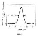
- Figure 3shows the measurement of width of the pulse which is carried out by a standard second order auto-correlation without signal background.
- Figure 1describes by way of example a embodiment of the device according to the invention.
- a cavity resonant 20delimited by a first mirror 1 and a second mirror 8 and on the other hand an optical means non-linear 10 comprising said second mirror 8.
- the first mirror 1is with high reflection, preferably total, and the second mirror 8 is a dichroic mirror.
- an active medium 5which can conventionally be an Nd: YAG medium (Yttrium Aluminum Garnet doped with Neodymium), Yb: YAG, Cr: YAG, Nd: YLF, Nd: glass, Ti: sapphire, Cr: forsterite or Yb: glass.
- the mediumis suitable for emitting under stimulation of laser beams at a frequency fundamental ⁇ 1. The choice of such an environment is dictated by the wavelength of the laser and the spectral width of the gain desired.
- the energy of the electric pumpis ⁇ 17 J, while the repetition frequency is 20 Hz.
- the intensity limiter for active blocking modeincludes an AOML 2 element (photo-acoustic blocker mode) located near the high reflection mirror 1 and a GaAs plate 4.
- the total cavity lengthis approximately 1.5 m and is adapted to the modulation frequency of 100 MHz AOML.
- the non-linear optical means 10has a reflection coefficient greater than 99% at 532 nm and equal to 25% at 1064 nm.
- non-linear crystalscould be used such as LBO (Lithium Triborate), KDP (Potassium Dihydrogen-Phosphate), KTP (Potassium Titanyl Phosphate), BBO (Beta-Barium Borate), PPLN (Periodically Poled Lithium Niobate) or KNbO 3 (Potassium Niobate).
- LBOLithium Triborate
- KDPPotassium Dihydrogen-Phosphate
- KTPPotassium Titanyl Phosphate
- BBOBeta-Barium Borate
- PPLNPeriodically Poled Lithium Niobate
- KNbO 3Potassium Niobate
- Figure 2shows the train envelope pulse length of 2 ⁇ s as measured by a p-i-n photodiode with a bandwidth oscilloscope of 60 MHz.
- the first part of the envelope (0-500 ns)is characterized by rapid variation of energy pulse and is followed by a plateau of 600 to 1800 ns characterized by an almost constant pulse energy, estimated at 10 ⁇ J / pulse.
- Figure 3shows the width measurement pulses in the middle of the envelope tray of the train. This measurement is performed by auto-correlation of the standard second order without background signal by synchronizing the 50 ns window of the signal integrator autocorrelation on the middle of the stable plateau of train envelope.
- the pulsed laser equipped with the device described in this documentpresents the characteristics ideal for synchronous oscillator pumping parametric optical.
- the intra- or extra-cavity of passive and active modification elements and polarization selectionsuch as Pockels, polarizers and retarder blades will allow select single energetic pulses.
Landscapes
- Physics & Mathematics (AREA)
- Electromagnetism (AREA)
- Engineering & Computer Science (AREA)
- Plasma & Fusion (AREA)
- Optics & Photonics (AREA)
- Nonlinear Science (AREA)
- Lasers (AREA)
- Optical Modulation, Optical Deflection, Nonlinear Optics, Optical Demodulation, Optical Logic Elements (AREA)
- Optical Communication System (AREA)
Abstract
Description
Translated fromFrenchLa présente invention se rapporte à undispositif et à un procédé permettant le mode-blocage d'unlaser, et en particulier d'un laser fonctionnant en modepulsé.The present invention relates to adevice and method for blocking mode of alaser, and in particular of a laser operating in modepulsed.
Une cavité laser est constituée d'un milieuamplificateur de lumière placé au sein d'une cavitérésonnante délimitée par deux miroirs orientés en auto-collimation,c'est-à-dire face à face. Lorsque le milieuamplificateur est activé, une oscillation optique estentretenue dans la cavité, de sorte que le dispositifpuisse émettre un faisceau optique caractérisé par unebrillance spatiale et spectrale très élevée.A laser cavity is made up of a mediumlight amplifier placed within a cavityresonant delimited by two mirrors oriented in self-collimation,that is to say face to face. When the middleamplifier is activated, optical oscillation ismaintained in the cavity, so that the devicecan emit an optical beam characterized by avery high spatial and spectral brightness.
Le mode-blocage d'une cavité laser consiste àforcer la circulation d'impulsions optiques brèves dans ladite cavité résonnante, de manière à générer des impulsionsde forte intensité crête et d'une durée typiquementinférieure à 100 picosecondes pouvant aller jusqu'àquelques femtosecondes en fonction du milieu amplificateurutilisé.The blocking mode of a laser cavity consists offorce the circulation of brief optical pulses in thesaid resonant cavity, so as to generate pulseshigh peak intensity and typically durationless than 100 picoseconds up toa few femtoseconds depending on the amplifying mediumused.
Parmi les lasers, on peut distinguer leslasers de type continu où le milieu amplificateur estactivé de manière permanente, c'est-à-dire sur des échellesde temps de plusieurs secondes à plusieurs heures. Un lasercontinu mode-bloqué pourra donc générer des impulsions brèves à un taux de répétition de l'ordre de quelquesdizaines à quelques centaines de mégahertz correspondant autemps de circulation (aller-retour) des impulsions dans lacavité résonnante.Among the lasers, we can distinguishcontinuous type lasers where the amplifying medium ispermanently activated, i.e. on scalesfrom several seconds to several hours. A lasercontinuous mode-blocked can therefore generate pulsesbrief at a repeat rate of the order of a fewtens to a few hundred megahertz corresponding to thecirculation time (round trip) of the pulses in theresonant cavity.
Ce taux de répétition élevé, implique que cetype de laser émettra des impulsions optiques de faibleénergie. Ce type de laser est néanmoins adéquat, pour denombreuses applications requérant une puissance optiquemoyenne élevée mais pouvant se satisfaire d'énergieimpulsionnelle faible telles que la technologie LIDAR, oules spectroscopies «linéaires» d'absorption, dephotoionisation, de fluorescence,...This high repetition rate implies thattype of laser will emit low optical pulsesenergy. This type of laser is nevertheless adequate, formany applications requiring optical powermedium high but can be satisfied with energyweak pulse such as LIDAR technology, or“linear” absorption spectroscopies,photoionization, fluorescence, ...
D'autre part, il existe des lasers de typepulsé caractérisés par un cycle de travail très faible dumilieu amplificateur (inférieure à 1/50). Ce dernier estactivé pendant un courte période, typiquement inférieure à1 milliseconde à un faible taux de répétition typiquementde quelques dizaines de hertz. En mode pulsé, le milieuamplificateur peut être temporairement très fortementactivé, correspondant à un stockage important d'énergieoptique dans le milieu amplificateur, de sorte qu'un laserpulsé mode-bloqué pourra générer des impulsions nettementplus énergétiques que celles générées par les lasersmode-bloqué de type continu. Par contre, le fait d'unepart, que le coefficient d'amplification du milieuamplificateur ne soit pas constant pendant la périodetransitoire d'activation et, d'autre part, que lastabilisation de l'oscillation optique dans la cavité laserest un processus dynamique qui requiert un certain temps etpeut donc être incomplète pendant le temps d'activation dumilieu amplificateur, limite l'efficacité du mode-blocageet par conséquent, la brièveté et la stabilité énergétiquedes dites impulsions optiques générées.On the other hand, there are lasers of the typepulsed characterized by a very weak work cycle of theamplifying medium (less than 1/50). This last one isactivated for a short time, typically less than1 millisecond at a low repetition rate typicallyof a few tens of hertz. In pulsed mode, the middleamplifier can be temporarily very stronglyactivated, corresponding to significant energy storageoptics in the amplifying medium, so that a laserpulsed mode-blocked will generate pulses clearlymore energetic than those generated by lasersmode-blocked continuous type. On the other hand, the fact of ashare, that the amplification coefficient of the mediumamplifier is not constant during the periodtransient activation and, secondly, that thestabilization of optical oscillation in the laser cavityis a dynamic process that takes time andmay therefore be incomplete during the activation time of theamplifying medium, limits the effectiveness of blocking modeand therefore brevity and energy stabilitysaid optical pulses generated.
Les lasers pulsés sont utilisés dans lesprocessus de fabrication nécessitant des impulsionsoptiques de forte énergie tels que pour l'ablation dematériaux, la découpe laser, traitement de surface, ainsipour les spectroscopies optiques « non-linéaires» tellesque l'ionisation résonnante à plusieurs photons, laspectroscopie de génération de fréquence somme ainsi quetoutes techniques requérant un faible taux de répétition dulaser (mesures résolues en temps).Pulsed lasers are used inmanufacturing process requiring pulseshigh energy optics such as for the ablation ofmaterials, laser cutting, surface treatment, as wellfor "non-linear" optical spectroscopies suchthat the multiple photon resonant ionization, thesum frequency generation spectroscopy as well asall techniques requiring a low repetition rate of thelaser (measurements resolved in time).
Une manière d'obtenir le mode-blocage deslasers de type pulsé est d'insérer une cellule à colorant(solvant liquide), éventuellement associée à un limiteurd'intensité dans la cavité laser. Ce dispositif présenteplusieurs inconvénients, en particulier :
- la mobilité et l'inhomogéniété du solvant qui circuledans la cellule sont des facteurs d'instabilitéénergétique des impulsions émises.
- La dégradation chimique ou photochimique dudit colorantnécessite l'intervention régulière de personnesqualifiées pour obtenir une optimisation du processus demode-blocage.
- the mobility and the inhomogeneity of the solvent which circulates in the cell are factors of energetic instability of the emitted impulses.
- The chemical or photochemical degradation of said dye requires the regular intervention of qualified people to obtain an optimization of the mode-blocking process.
Le document US-A-4914658 décrit un laser àl'état solide tel qu'un laser Yttrium Aluminium Garnet dopéau Néodyme (Nd:YAG) auquel est adjoint un cristal non-linéaireet un miroir dichroïque en vue de créer un moyenoptique non-linéaire permettant le mode-blocage du laser.Dans la forme la plus simple de mise en oeuvre dudispositif, le cristal non-linéaire permet de générer unfaisceau de deuxième harmonique à partir du faisceaufondamental amplifié par le milieu amplificateur.L'oscillation dans la cavité résonnante de la portion dufaisceau fondamental non-convertie par le cristal non-linéaire,est discriminée négativement grâce à un miroir dichroïque qui doit présenter un coefficient de réflexion àla fréquence de deuxième harmonique supérieur à celui à lafréquence fondamentale.Document US-A-4914658 describes a laser withsolid state such as a doped Yttrium Aluminum Garnet laserNeodymium (Nd: YAG) to which is added a non-linear crystaland a dichroic mirror in order to create a waynon-linear optics allowing laser blocking mode.In the simplest form of implementation of thedevice, the nonlinear crystal can generate asecond harmonic beam from the beamfundamental amplified by the amplifying medium.The oscillation in the resonant cavity of the portion of thefundamental beam not converted by non-linear crystal,is negatively discriminated against by a mirrordichroic which must have a reflection coefficient atthe frequency of second harmonic higher than that at thefundamental frequency.
L'ajustement de la distance optique entre lecristal non-linéaire et le miroir dichroïque permetd'obtenir un déphasage adéquat entre le faisceaufondamental et le faisceau de deuxième harmonique afind'obtenir une reconversion efficace du faisceau de deuxièmeharmonique en faisceau fondamental dans le cristal non-linéaire.Ce déphasage peut aussi être obtenu par insertiond'une lame transparente entre le cristal non-linéaire et lemiroir dichroïque.Adjusting the optical distance between thenon-linear crystal and the dichroic mirror allowsobtain an adequate phase shift between the beamfundamental and the second harmonic beam soto obtain an efficient reconversion of the second beamharmonic in fundamental beam in the non-linear crystal.This phase shift can also be obtained by insertionof a transparent plate between the non-linear crystal and thedichroic mirror.
Le moyen optique non linéaire a pour fonctiond'augmenter le facteur qualité de la cavité laser, c'est-à-direde diminuer les pertes d'énergie du faisceau laser parréflexion contre le miroir dichroïque, quand la puissanceinstantanée du faisceau à la fréquence fondamentale générépar le milieu amplificateur augmente. En d'autres termes,le moyen optique non linéaire induit une rétroactionpositive sur le facteur qualité de la cavité laser enfonction de la puissance instantanée du faisceau à lafréquence fondamentale.The function of non-linear optical means isincrease the quality factor of the laser cavity, i.e.to reduce the energy losses of the laser beam byreflection against the dichroic mirror, when the powerinstant of the beam at the fundamental frequency generatedby the amplifying medium increases. In other words,nonlinear optical means induces feedbackpositive on the quality factor of the laser cavity infunction of the instantaneous beam power at thefundamental frequency.
Le dispositif optique non-linéaire demode-blocage est en outre caractérisé en ce que le rapportdes puissances du faisceau de deuxième harmonique parrapport au faisceau à la fréquence fondamentale augmenteavec la puissance du faisceau à la fréquence fondamentale.The non-linear optical device ofblocking mode is further characterized in that the ratiosecond harmonic beam powers byratio to the beam at the fundamental frequency increaseswith the beam power at the fundamental frequency.
Le document EP-A-0951111 propose undispositif et une méthode pour permettre le mode-blocaged'un laser, de préférence fonctionnant également en modecontinu, qui se basent sur le principe décrit dans ledocument US-A-4914658. Dans ce cas de figure, il estproposé de convertir une partie du faisceau laser à lafréquence fondamentale en un faisceau de deuxième harmonique par l'utilisation d'un cristal non-linéaire.L'oscillation dans la cavité résonnante de la portion dufaisceau fondamental non-convertie dans le cristal non-linéaireest discriminée négativement grâce à lacombinaison d'une lame retardatrice et d'un polariseur.Dans ce document, le milieu amplificateur est duNd:Vanadate, le cristal non linéaire est du LithiumTriborate et la lame retardatrice présente un retard deλ/4= 1064 nm et λ/2=532 nm. La lame retardatrice est placéeentre le cristal non linéaire et le miroir dichroïquetandis que le polariseur est placé entre le milieuamplificateur et le cristal non linéaire.Document EP-A-0951111 proposes adevice and method for enabling blocking modea laser, preferably also operating inwhich are based on the principle described in thedocument US-A-4914658. In this case, it isproposed to convert part of the laser beam to thefundamental frequency in a second beamharmonic through the use of a non-linear crystal.The oscillation in the resonant cavity of the portion of thefundamental beam not converted in non-linear crystalis negatively discriminated against thanks to thecombination of a retarder plate and a polarizer.In this document, the amplifying medium is of theNd: Vanadate, the non-linear crystal is LithiumTriborate and the delay blade has a delay ofλ / 4 = 1064 nm and λ / 2 = 532 nm. The delay blade is placedbetween the nonlinear crystal and the dichroic mirrorwhile the polarizer is placed between the middleamplifier and the nonlinear crystal.
Il est précisé dans ce document que le miroirdichroïque, placé derrière le cristal non-linéaire,présente un coefficient de réflexion à la fréquence dedeuxième harmonique qui n'est pas plus élevé que lecoefficient de réflexion à la fréquence fondamentale.It is specified in this document that the mirrordichroic, placed behind the non-linear crystal,has a reflection coefficient at the frequency ofsecond harmonic which is not higher than thereflection coefficient at the fundamental frequency.
Le moyen optique non linéaire décrit dans cedocument a pour fonction d'augmenter le facteur qualité dela cavité laser, c'est-à-dire de diminuer les pertesd'énergie du faisceau laser par réflexion contre lepolariseur, quand la puissance instantanée du faisceau à lafréquence fondamentale généré par le milieu amplificateuraugmente. En d'autres termes, le moyen optique non linéaireinduit une rétroaction positive sur le facteur qualité dela cavité laser en fonction de la puissance instantanée dufaisceau à la fréquence fondamentale.The nonlinear optical means described in thisdocument has the function of increasing the quality factor ofthe laser cavity, i.e. to reduce lossesenergy of the laser beam by reflection against thepolarizer, when the instantaneous power of the beam at thefundamental frequency generated by the amplifying mediumincreases. In other words, the nonlinear optical meansinduces a positive feedback on the quality factor ofthe laser cavity as a function of the instantaneous power of thebeam at the fundamental frequency.
Les dispositifs décrits dans les deuxdocuments précédents US-A-4914658 et EP-0951111 permettentle mode-blocage efficace des lasers continus. Par exemple,des impulsions aussi brèves que ∼10 picosecondes LTMH(largeur totale à mi-hauteur) peuvent être généréeslorsqu'un milieu amplificateur Nd:YAG est utilisé. Par contre ces dispositifs fonctionnent mal dans le cas delasers pulsés. Les durées d'impulsions les plus brèvesjamais obtenues grâce au dispositif tel que décrit dans ledocument US-A-49146558 sont de 35 picosecondes LTMH(largeur total à mi-hauteur)dans le cas d'un laser Nd:YAGpulsé. Ces mauvaises performances résultent du fait que lecoefficient d'amplification du milieu actif, l'énergie desimpulsions optiques et donc le rendement de conversion ducristal non-linéaire utilisé dans le dispositif non-linéairevarient fortement au cours de la périoded'activation du milieu amplificateur ce qui empêche unstabilisation de l'oscillation optique dans la cavitérésonnante. D'autre part, le nombre réduit d'aller-retourintracavité, et donc d'interaction avec le dispositif non-linéaire,réalisés par les impulsions optiques pendant letemps d'activation du milieu amplificateur limite aussil'efficacité du mode-blocage.The devices described in bothprevious documents US-A-4914658 and EP-0951111 allowthe efficient blocking mode of continuous lasers. For example,pulses as short as ∼10 picoseconds LTMH(full width at half height) can be generatedwhen an Nd: YAG amplifying medium is used. Throughagainst these devices malfunction in the case ofpulsed lasers. Shortest pulse durationsnever obtained thanks to the device as described in thedocument US-A-49146558 are 35 picoseconds LTMH(full width at half height) in the case of an Nd: YAG laserpulsed. These poor performances result from the fact that theamplification coefficient of the active medium, the energy ofoptical pulses and therefore the conversion efficiency of thenon-linear crystal used in the non-linear devicevary greatly over the periodactivating the amplifying medium which prevents astabilization of optical oscillation in the cavityresonant. On the other hand, the reduced number of round tripsintracavity, and therefore interaction with the non-linear device,made by optical pulses duringactivation time of the amplifying medium also limitsthe effectiveness of blocking mode.
La présente invention vise à fournir undispositif et un procédé de mode-blocage d'un laserpermettant d'obtenir des impulsions particulièrement brèveset présentant une grande stabilité énergétique, même dansle cas d'un laser pulsé.The present invention aims to provide alaser mode-blocking device and methodproviding particularly short pulsesand with great energy stability, even inthe case of a pulsed laser.
La présente invention vise en particulier às'affranchir des inconvénients des dispositifs et procédésde l'état de la technique.The present invention aims in particular toovercoming the disadvantages of devices and processesstate of the art.
En particulier, la présente invention vise àproposer un dispositif constitué uniquement d'élémentssolides et donc simple à entretenir comparativement auxdispositifs utilisant des colorants (solvants liquides),robuste et peu coûteux. En outre, les différentsconstituants utilisés devront présenter un faible taux dedégradation dans le temps.In particular, the present invention aims topropose a device made up entirely of elementssolid and therefore easy to maintain compared todevices using dyes (liquid solvents),robust and inexpensive. In addition, the differentconstituents used should have a low rate ofdegradation over time.
La présente invention se rapporte à undispositif pour le mode-blocage d'un laser, en particulierun laser de type pulsé, comprenant une cavité laserdélimitée par un premier miroir et un second miroir, munied'un milieu actif pour l'amplification du faisceau laser defréquence fondamentale, et un moyen optique non-linéairesolide qui comprend au moins ledit second miroir et quiprésente un coefficient de réflexion qui augmente avecl'intensité du faisceau, caractérisé en ce que leditdispositif comprend en outre dans la cavité laser unlimiteur d'intensité solide dont le coefficient detransmission du faisceau fondamental qui diminue avecl'intensité dudit faisceau laser.The present invention relates to adevice for the mode-blocking of a laser, in particulara pulsed type laser, comprising a laser cavitydelimited by a first mirror and a second mirror, providedan active medium for the amplification of the laser beamfundamental frequency, and non-linear optical meanssolid which comprises at least said second mirror and whichhas a reflection coefficient which increases withbeam intensity, characterized in that saiddevice further comprises in the laser cavity asolid current limiter whose coefficient oftransmission of the fundamental beam which decreases withthe intensity of said laser beam.
Plus précisément, alors que les dispositifstels que décrits dans le document US-A-4914658 etEP-0951111 ne présentent, par l'utilisation d'un moyenoptique non linéaire, qu'une rétroaction positive sur lefacteur de qualité de la cavité résonnante laser enfonction de la puissance du faisceau fondamental, ledispositif selon la présente invention présente, parl'utilisation conjointe du moyen optique non linéaire et dulimiteur d'intensité, à la fois une rétroaction positive etune rétroaction négative sur ce facteur de qualité. Ceciest dû au fait que le moyen optique non linéaire présenteun coefficient de réflexion qui augmente avec l'intensitédu faisceau fondamental tandis que le limiteur d'intensitéprésentant un coefficient de transmission à la fréquencefondamentale du laser qui diminue avec l'intensité dufaisceau fondamental.Specifically, while the devicesas described in document US-A-4914658 andEP-0951111 do not present, by the use of a meansnonlinear optics, that a positive feedback on thequality factor of the laser resonant cavity independing on the power of the fundamental beam, thedevice according to the present invention presents, bythe joint use of non-linear optical means andintensity limiter, both positive feedback andnegative feedback on this quality factor. Thisis due to the fact that the non-linear optical means hasa reflection coefficient which increases with intensityof the fundamental beam while the intensity limiterhaving a frequency transmission coefficientfundamental of the laser which decreases with the intensity of thefundamental beam.
L'utilisation conjointe du moyen optique non-linéaireet du limiteur d'intensité implique que le rapportde puissance du faisceau de deuxième harmonique par rapport au faisceau fondamental n'augmente plus avec l'intensitédu faisceau fondamental lorsque cette dernière intensitédépasse le seuil de fonctionnement de limiteur d'intensité.Joint use of non-linear optical meansand intensity limiter implies that the ratiosecond harmonic beam power comparedto the fundamental beam no longer increases with intensityof the fundamental beam when this last intensityexceeds the current limiter operating threshold.
Avantageusement, le moyen optique non-linéairecomprend ledit second miroir qui correspond à unmiroir dichroïque et un cristal non-linéaire convertisseurde la fréquence laser.Advantageously, the non-linear optical meansincludes said second mirror which corresponds to adichroic mirror and a nonlinear crystal converterof the laser frequency.
Le moyen optique non-linéaire peut égalementne comprendre que ledit second miroir qui correspond alorsà un absorbeur saturable anti-résonnant Fabry-Perotconstruit à partir d'une superposition de films semi-conducteursdiélectriques ou métalliques.Nonlinear optical means can alsounderstand only said second mirror which then correspondswith a saturable anti-resonant absorber Fabry-Perotconstructed from a superimposition of semiconductor filmsdielectric or metallic.
Le moyen optique non linéaire peut égalementcomprendre ledit second miroir qui correspond à un miroirdichroïque, un cristal non-linéaire convertisseur defréquence et au moins un polariseur.Nonlinear optical means can alsounderstand said second mirror which corresponds to a mirrordichroic, a nonlinear crystal converterfrequency and at least one polarizer.
Le limiteur d'intensité estconstitué par une lame réalisée en un matériau semi-conducteurGaAs, CdSe ou InP.The intensity limiter isconsisting of a blade made of a semiconductor materialGaAs, CdSe or InP.
De manière avantageuse, le limiteurd'intensité est disposé entre le milieu amplificateur et lemoyen optique non linéaire.Advantageously, the limiterintensity is arranged between the amplifying medium and thenon-linear optical means.
De manière particulièrement avantageuse, lelimiteur d'intensité et le moyen optique non linéaire sontdisposés de part et d'autre du milieu amplificateur.Particularly advantageously, theintensity limiter and the nonlinear optical means arearranged on either side of the amplifying medium.
La présente invention se rapporte également àun procédé pour le mode-blocage d'un laser, en particulierun laser de type pulsé, comprenant:
- l'émission d'un faisceau de rayonnement laser defréquence fondamentale par stimulation d'un milieu laseractif,
- la conversion du faisceau de fréquence fondamentale enun faisceau de fréquence harmonique,
- le renvoi du faisceau de fréquence harmonique vers lacavité résonnante
- la reconversion du faisceau de fréquence harmonique enun faisceau de fréquence fondamentale,
- the emission of a beam of laser radiation of fundamental frequency by stimulation of an active laser medium,
- the conversion of the fundamental frequency beam into a harmonic frequency beam,
- the return of the harmonic frequency beam to the resonant cavity
- the conversion of the harmonic frequency beam into a fundamental frequency beam,
La figure 1 décrit une forme particulièred'exécution du dispositif permettant la réalisation d'unoscillateur Nd:YAG selon le principe de la présenteinvention.Figure 1 describes a particular shapeof execution of the device allowing the realization of aNd: YAG oscillator according to the principle of thisinvention.
La figure 2 représente l'enveloppe du traind'impulsions obtenue pour l'oscillateur Nd:YAG tel quedécrit à la figure 1.Figure 2 shows the train envelopeof pulses obtained for the Nd: YAG oscillator such thatdescribed in figure 1.
La figure 3 représente la mesure de lalargeur de l'impulsion qui est effectuée par uneauto-corrélation de second ordre standard sans signal defond.Figure 3 shows the measurement ofwidth of the pulse which is carried out by astandard second order auto-correlation without signalbackground.
La figure 1 décrit à titre d'exemple uneforme d'exécution du dispositif selon l'invention. Onréalise de manière classique d'une part une cavitérésonnante 20 délimitée par un premier miroir 1 et unsecond miroir 8 et d'autre part un moyen optiquenon-linéaire 10 comprenant ledit second miroir 8. Lepremier miroir 1 est à réflexion élevée, de préférencetotale, et le second miroir 8 est un miroir dichroïque. Ausein de la cavité résonnante 20, on dispose un milieu actif5, qui peut être de manière classique un milieu Nd:YAG(Yttrium Aluminium Garnet dopé au Néodyme), Yb:YAG, Cr:YAG,Nd:YLF, Nd:verre, Ti:saphir, Cr:forstérite ou encoreYb:verre. Le milieu est adapté pour émettre sousstimulation des rayons laser à une fréquencefondamentale ω1. Le choix d'un tel milieu est dicté par lalongueur d'onde du laser et la largeur spectrale du gaindésirées.Figure 1 describes by way of example aembodiment of the device according to the invention. Weon the one hand, it produces a cavityresonant 20 delimited by a
Selon une forme d'exécution de l'invention,le milieu amplificateur est un barreau de cristal Nd:YAG 5présentant des dimensions de 115 X 7 mm qui est pompé pardeux lampes à flash permettant la stimulation d'un faisceaulaser d'une fréquence fondamentale ω1 = 1064 nm.According to one embodiment of the invention,the amplifying medium is an Nd:
L'énergie de la pompe électrique est de∼17 J, tandis que la fréquence de répétition est de 20 Hz.The energy of the electric pump is∼17 J, while the repetition frequency is 20 Hz.
Deux lentilles 61 et 62 pourvues d'unrevêtement anti-reflets et caractérisées respectivement pardes distances focales de 100 et de -40 mm forment letélescope 6. Un diaphragme 3 de 0,8 mm limite lefonctionnement du laser à un seul mode transversal. Lelimiteur d'intensité destiné au mode-blocage actif seloncette forme d'exécution comprend un élément AOML 2 (mode-bloqueur photo-acoustique) situé à proximité dumiroir à réflexion élevée 1 et une lame de GaAs 4. Lalongueur de la cavité totale est d'approximativement 1,5 met est adaptée à la fréquence de modulation de 100 Mhz del'AOML.Two
Le moyen optique non-linéaire 10 comprend enplus du miroir dichroïque 8, selon la forme d'exécutionreprésentée à la figure 1, un cristal non-linéaire 7 detype BBO d'une longueur de 3 mm qui permet la générationd'un faisceau de second harmonique (ω2 = 532 nm) parinteraction de type I. Le moyen optique non-linéaire 10présente un coefficient de réflexion supérieur à 99% à532 nm et égal à 25% à 1064 nm. D'autres cristauxnon-linéaires pourraient être utilisés tels que le LBO(Lithium Triborate), le KDP (Potassium Dihydrogéno-Phosphate),le KTP (Potassium Titanyl Phosphate), le BBO(Bêta-Baryum Borate), le PPLN (Periodically Poled LithiumNiobate) ou encore le KNbO3 (Potassium Niobate). La lame deGaAs est placée à incidence de Brewster. L'ajustement de ladistance séparant le cristal non-linéaire 7 du miroirdichroïque 8 permet le réglage du déphasage entre lefaisceau fondamental et le faisceau de second harmoniquelors du processus de reconversion.The non-linear optical means 10 comprises, in addition to the
Lorsque cette distance est correctementajustée, on observe une augmentation notable de l'intensitédu faisceau généré par la cavité, ce qui révèle lemode-blocage passif efficace de l'oscillateur YAG.When this distance is correctadjusted, there is a noticeable increase in intensityof the beam generated by the cavity, which reveals theeffective passive blocking mode of the YAG oscillator.
La puissance moyenne de sortie de la cavitélaser est de ∼30 mW (énergie de traind'impulsions = 1,5 mJ) pour une énergie de pompe électriquede ∼17 J lorsque l'élément AOML 2 est utilisé dans lacavité.The average output power of the cavitylaser is ∼30 mW (train energypulse = 1.5 mJ) for an electric pump energyof ∼17 J when the
La figure 2 représente l'enveloppe du traind'impulsions long de 2 µs telle que mesurée par unephotodiode p-i-n avec un oscilloscope de largeur de bandede 60 MHz. La première partie de l'enveloppe (0-500 ns) estcaractérisée par une variation rapide de l'énergied'impulsion et est suivie par un plateau de 600 à 1800 nscaractérisé par une énergie d'impulsion quasi constante,estimée à 10 µJ/impulsion.Figure 2 shows the train envelopepulse length of 2 µs as measured by ap-i-n photodiode with a bandwidth oscilloscopeof 60 MHz. The first part of the envelope (0-500 ns) ischaracterized by rapid variation of energypulse and is followed by a plateau of 600 to 1800 nscharacterized by an almost constant pulse energy,estimated at 10 µJ / pulse.
Bien que des études précédentes aient révéléque ce dispositif pouvait fonctionner sans le mode-blocageactif, un fonctionnement beaucoup plus stable del'oscillateur YAG a été observé lorsque l'élément AOML estutilisé dans la cavité.Although previous studies have foundthat this device could work without blocking modeactive, much more stable operation ofthe YAG oscillator was observed when the AOML element isused in the cavity.
La figure 3 présente la mesure de la largeurdes impulsions au milieu du plateau de l'enveloppe dutrain. Cette mesure est réalisée par auto-corrélation dusecond ordre standard sans signal de fond en synchronisantla fenêtre de 50 ns de l'intégrateur de signald'auto-corrélation sur le milieu du plateau stable del'enveloppe des trains.Figure 3 shows the width measurementpulses in the middle of the envelope tray of thetrain. This measurement is performed by auto-correlation of thestandard second order without background signal by synchronizingthe 50 ns window of the signal integratorautocorrelation on the middle of the stable plateau oftrain envelope.
Supposant un profil gaussien, on déduit unedurée d'impulsion de 12 ps LTMH pour l'impulsionfondamentale. L'intensité crête à l'intérieur de la cavitéatteint une valeur de l'ordre de 55 MW/cm2, ce qui est enaccord avec le commencement de l'absorption à deux photonsdans un semi-conducteur de GaAs.Assuming a Gaussian profile, we deduce a pulse duration of 12 ps LTMH for the fundamental pulse. The peak intensity inside the cavity reaches a value of the order of 55 MW / cm2 , which is in agreement with the start of two-photon absorption in a GaAs semiconductor.
En conclusion, il est possible d'obtenir unedurée d'impulsion réduite à 12 ps ou même moins à partird'un laser Nd:YAG pulsé pompé par lampe à flash, encombinant un élément de rétroaction passif-négatifconstituant le limiteur d'intensité, qui est dans le casprésent une lame de GaAs, à un élément de rétroactionpositif qui est un moyen optique non-linéaire dans le présent cas, constitué d'un cristal non-linéaire (BBO)doubleur de fréquence associé à un miroir dichroïque.In conclusion, it is possible to obtain apulse duration reduced to 12 ps or even less fromof a pulsed Nd: YAG laser pumped by flash lamp, incombining a passive-negative feedback elementconstituting the intensity limiter, which is in the casepresent a GaAs blade, to a feedback elementpositive which is a nonlinear optical means in thepresent case, consisting of a non-linear crystal (BBO)frequency doubler associated with a dichroic mirror.
L'augmentation du nombre d'aller-retourréalisés par les impulsions optiques ainsi que leurstabilisation en énergie induite par le limiteurd'intensité constituent deux facteurs clé pour obtenir desimpulsions brèves. La durée de ces impulsions est trèsproche de la limite inférieure de ∼10 ps, imposée par latransformée de Fourier du spectre de gain du milieuamplificateur Nd:YAG.The increase in the number of round tripsmade by optical pulses and theirenergy stabilization induced by the limiterare two key factors for obtainingbrief pulses. The duration of these pulses is veryclose to the lower limit of ∼10 ps, imposed by theFourier transform of the middle gain spectrumNd: YAG amplifier.
Le laser pulsé équipé du dispositif décritdans le présent document présente les caractéristiquesidéales pour le pompage synchrone d'oscillateurparamétrique optique.The pulsed laser equipped with the device describedin this document presents the characteristicsideal for synchronous oscillator pumpingparametric optical.
D'autre part, l'interposition intra- ouextra-cavité d'éléments passifs et actifs de modificationet de sélection de polarisation tels que cellule dePockels, polariseurs et lames retardatrices permettra desélectionner des impulsions uniques énergétiques.On the other hand, the intra- orextra-cavity of passive and active modification elementsand polarization selection such asPockels, polarizers and retarder blades will allowselect single energetic pulses.
Claims (11)
- A device for mode-locking a laser, inparticular a laser of pulsed type, comprising aresonant cavity (20):said device further comprising a solid intensitylimiter (4), arranged in the resonant cavity (20) andwhose laser radiation transmission coefficientdecreases with the intensity of said radiation,characterized in that said intensity limiter (4)comprises a GaAs, CdSe or InP plate.delimited by a first mirror (1) and a secondmirror (8),provided with an amplifying active laser medium(5) for amplifying a laser radiation beam at thefundamental frequency (ω1),and with a solid non-linear optical means (10),comprising at least said second mirror (8), forthe reversible conversion of the fundamentalfrequency radiation (ω1) into a harmonicfrequency radiation (ω2), said non-linear opticalmeans (10) having a reflection coefficientincreasing with the intensity of radiation at thefundamental frequency;
- A device according to claim 1,characterized in that the non-linear optical means (10)comprises said second mirror (8) corresponding to adichroic mirror and a non-linear crystal (7) being ableto convert the fundamental frequency radiation into aharmonic frequency radiation.
- A device according to claim 1,characterized in that the non-linear optical means (10)comprises said second mirror (8) corresponding to adichroic mirror, a non-linear crystal (7) being able toconvert the fundamental frequency radiation into aharmonic frequency radiation and at least one elementfor modifying and/or selecting polarization.
- A device according to claim 2 or 3,characterized in that said non-linar crystal is a BBOcrystal.
- A device according to claim 1,characterized in that the non-linear optical means (10)only comprises the second mirror (8), said secondmirror corresponding to an anti-resonant Fabry-Perotsaturable absorber built up from overlapped dielectricor metallic semiconductor films.
- A device according to any one of thepreceding claims,characterized in that the intensitylimiter (4) and the non-linear optical means (10) arearranged on either side of the amplifying active medium(5).
- A device according to any one of thepreceding claims,characterized in that the intensitylimiter (4) is arranged between the non-linear opticalmeans (10) and the amplifying active medium (5).
- A device according to any one of thepreceding claims,characterized in that the amplifyingactive medium is a Nd:YAG crystal.
- A device according to any one of thepreceding claims,characterized in that the non-linearoptical means (10) has a second harmonic radiation (ω2) reflection coefficient higher than thefundamental frequency radiation (ω1) reflectioncoefficient.
- A device for mode-locking a laser, inparticular a laser of pulsed type, comprising aresonant cavity (20):characterized in that said device is provided with anintensity limiter comprising a GaAs, CdSe or InP platewith a transmission coefficient decreasing with theintensity of radiation at the fundamental frequency soas to provide together with said non-linear opticalmeans (10) both a positive feedback and a negativefeedback on the quality factor of the resonant cavity(20).delimited by a first mirror (1) and a secondmirror (8),provided with an amplifying active laser medium(5) for amplifying a laser radiation beam at thefundamental frequency (ω1),and with a solid non-linear optical means (10),comprising at least said second mirror (8), forthe reversible conversion of the fundamentalfrequency radiation (ω1) into a harmonicfrequency radiation (ω2), said non-linear opticalmeans (10) having a reflection coefficientincreasing with the intensity of radiation at thefundamental frequency;
- A method for mode-locking a laser, inparticular a laser of pulsed type,characterized inthat it comprises the steps of:emitting a laser radiation beam at the fundamentalfrequency (ω1) through stimulation of an activelaser medium (5),converting the fundamental frequency beam (ω1)into a harmonic frequency beam (ω2),returning the harmonic frequency beam (ω2) to theresonant cavity (20),reconverting the harmonic frequency beam (ω2)into a fundamental frequency beam (ω1), andlimiting the intensity of the fundamentalfrequency beam (ω1) within the resonant cavity(20), using at least one GaAs, CdSe or InP plate.
Applications Claiming Priority (3)
| Application Number | Priority Date | Filing Date | Title |
|---|---|---|---|
| BE9900314ABE1013518A6 (en) | 1999-05-03 | 1999-05-03 | Lock-mode laser pulse by combination of non-linear mirror and a limit of intensity. |
| BE9900314 | 1999-05-03 | ||
| PCT/BE2000/000049WO2000067351A1 (en) | 1999-05-03 | 2000-05-03 | Device and method for a laser blocked-mode |
Publications (2)
| Publication Number | Publication Date |
|---|---|
| EP1175716A1 EP1175716A1 (en) | 2002-01-30 |
| EP1175716B1true EP1175716B1 (en) | 2003-07-30 |
Family
ID=3891900
Family Applications (1)
| Application Number | Title | Priority Date | Filing Date |
|---|---|---|---|
| EP00926585AExpired - LifetimeEP1175716B1 (en) | 1999-05-03 | 2000-05-03 | Device and method for mode locking a laser |
Country Status (10)
| Country | Link |
|---|---|
| US (1) | US6928090B1 (en) |
| EP (1) | EP1175716B1 (en) |
| JP (1) | JP4509397B2 (en) |
| CN (1) | CN1349676A (en) |
| AT (1) | ATE246410T1 (en) |
| AU (1) | AU4528800A (en) |
| BE (1) | BE1013518A6 (en) |
| CA (1) | CA2367382C (en) |
| DE (1) | DE60004199T2 (en) |
| WO (1) | WO2000067351A1 (en) |
Families Citing this family (3)
| Publication number | Priority date | Publication date | Assignee | Title |
|---|---|---|---|---|
| US7356053B2 (en)* | 2003-10-06 | 2008-04-08 | Continuum Electro-Optics, Inc. | Mode-locked laser with variable pulse duration |
| US7463657B2 (en)* | 2003-10-09 | 2008-12-09 | Coherent, Inc. | Intracavity frequency-tripled CW laser |
| IT201900020456A1 (en) | 2019-11-06 | 2021-05-06 | Lithium Lasers Srl | Apparatus and method for the generation of ultra-short laser light pulses in passive mode-locking regime. |
Family Cites Families (15)
| Publication number | Priority date | Publication date | Assignee | Title |
|---|---|---|---|---|
| DE3826716A1 (en)* | 1987-10-30 | 1990-02-08 | Max Planck Gesellschaft | FASHION COUPLED LASER |
| US4829528A (en)* | 1988-09-22 | 1989-05-09 | Allied-Signal Inc. | Interlocked ring intracavity raman laser method of generating raman shifted laser output |
| US5986828A (en)* | 1988-11-01 | 1999-11-16 | The United States Of America As Represented By The Secretary Of The Army | Optical power limiter utilizing nonlinear refraction |
| US5257274A (en)* | 1991-05-10 | 1993-10-26 | Alliedsignal Inc. | High power laser employing fiber optic delivery means |
| JPH06214169A (en)* | 1992-06-08 | 1994-08-05 | Texas Instr Inc <Ti> | Controllable optical and periodic surface filter |
| DE69331788T2 (en)* | 1992-06-19 | 2002-11-07 | Sony Corp., Tokio/Tokyo | laser beam generator |
| US5436920A (en)* | 1993-05-18 | 1995-07-25 | Matsushita Electric Industrial Co., Ltd. | Laser device |
| KR0149770B1 (en)* | 1995-02-25 | 1998-12-01 | 심상철 | Passivity q-switch laser having daul cavity structure |
| US6021140A (en) | 1998-04-17 | 2000-02-01 | Spectra-Physics Lasers, Inc. | Polarization based mode-locking of a laser |
| US6252892B1 (en)* | 1998-09-08 | 2001-06-26 | Imra America, Inc. | Resonant fabry-perot semiconductor saturable absorbers and two photon absorption power limiters |
| US6275512B1 (en)* | 1998-11-25 | 2001-08-14 | Imra America, Inc. | Mode-locked multimode fiber laser pulse source |
| US6144679A (en)* | 1999-01-15 | 2000-11-07 | Science Applications International Corporation | Method and apparatus for providing a coherent terahertz source |
| US6546027B1 (en)* | 1999-12-01 | 2003-04-08 | Hoya Photonics, Inc. | Laser saturable absorber and passive negative feedback elements, and method of producing energy output therefrom |
| DE10013184A1 (en)* | 2000-03-17 | 2001-09-20 | Deutsche Telekom Ag | Selective photon polarization method for quantum processor involves activating electrooptical modulator in specific time, during which probability of presence of photon is maximum |
| US6813951B2 (en)* | 2000-07-13 | 2004-11-09 | National Research Council Of Canada | Laser-ultrasonic testing system |
- 1999
- 1999-05-03BEBE9900314Apatent/BE1013518A6/ennot_activeIP Right Cessation
- 2000
- 2000-05-03CACA2367382Apatent/CA2367382C/ennot_activeExpired - Fee Related
- 2000-05-03JPJP2000616098Apatent/JP4509397B2/ennot_activeExpired - Fee Related
- 2000-05-03AUAU45288/00Apatent/AU4528800A/ennot_activeAbandoned
- 2000-05-03WOPCT/BE2000/000049patent/WO2000067351A1/enactiveIP Right Grant
- 2000-05-03EPEP00926585Apatent/EP1175716B1/ennot_activeExpired - Lifetime
- 2000-05-03USUS10/009,337patent/US6928090B1/ennot_activeExpired - Fee Related
- 2000-05-03DEDE60004199Tpatent/DE60004199T2/ennot_activeExpired - Lifetime
- 2000-05-03ATAT00926585Tpatent/ATE246410T1/ennot_activeIP Right Cessation
- 2000-05-03CNCN00807086Apatent/CN1349676A/enactivePending
Also Published As
| Publication number | Publication date |
|---|---|
| ATE246410T1 (en) | 2003-08-15 |
| JP4509397B2 (en) | 2010-07-21 |
| BE1013518A6 (en) | 2002-03-05 |
| EP1175716A1 (en) | 2002-01-30 |
| AU4528800A (en) | 2000-11-17 |
| JP2002543629A (en) | 2002-12-17 |
| DE60004199D1 (en) | 2003-09-04 |
| DE60004199T2 (en) | 2004-04-15 |
| CN1349676A (en) | 2002-05-15 |
| CA2367382C (en) | 2010-07-20 |
| CA2367382A1 (en) | 2000-11-09 |
| WO2000067351A1 (en) | 2000-11-09 |
| US6928090B1 (en) | 2005-08-09 |
Similar Documents
| Publication | Publication Date | Title |
|---|---|---|
| EP3488290B1 (en) | System for generating brief or ultra-brief light pulses | |
| Grabtchikov et al. | All solid-state diode-pumped Raman laser with self-frequency conversion | |
| Kato | High-power difference-frequency generation at 5-11 µm in AgGaS 2 | |
| EP3738180A1 (en) | Laser system and method for generating laser pulses with very high repetition rate | |
| Bäder et al. | Pulsed nanosecond optical parametric generator based on periodically poled lithium niobate | |
| Sorokin et al. | 1 Watt femtosecond mid-IR Cr: ZnS laser | |
| CN103401135B (en) | Adopt raman frequency conversion by the method for laser amplifier and device thereof | |
| Salour | Powerful dye laser oscillator-amplifier system for high resolution and coherent pulse spectroscopy | |
| Danailov et al. | A novel method of ultrabroadband laser generation | |
| Riesbeck et al. | Pulsed solid-state laser system with fiber phase conjugation and 315 W average output power | |
| EP1175716B1 (en) | Device and method for mode locking a laser | |
| Sennaroglu et al. | Concentration dependence of fluorescence and lasing efficiency in Cr2+: ZnSe lasers | |
| EP4291949A1 (en) | System and method for generating a light pulse with sub-picosecond duration that is duration and/or repetition frequency adjustable | |
| WO2007138013A1 (en) | Laser source for lidar application | |
| Behrendt et al. | Modular lidar systems for high-resolution 4-dimensional measurements of water vapor, temperature, and aerosols | |
| EP3227976B1 (en) | Bi-frequency laser emission system | |
| US20120026579A1 (en) | Resonant Optical Amplifier | |
| Takada et al. | Flashlamp-pumped Cr: LiSAF laser amplifier | |
| Ju et al. | High power 1.57-? m OPO pumped by MOPA with SBS | |
| FR2742009A1 (en) | METHOD AND DEVICE FOR PRODUCING A LASER PULSE OF A LONG ADJUSTABLE DURATION | |
| Seeger et al. | 35W Carrier-Envelope-Phase-Stable Few-Cycle Mid-Infrared OPCPA at 10 kHz | |
| US20060050745A1 (en) | Method and system for generating ultrashort laser pulses | |
| Das et al. | Power Scaling of a Narrowband PPLN Non-Resonant Optical Parametric Oscillator | |
| Slobodchikov et al. | High-Power and High-Repetition Rate Femtosecond Chromium-Doped Forsterite Laser | |
| FR2553204A2 (en) | METHOD AND DEVICE FOR CREATING BRIEF LIGHT PULSES |
Legal Events
| Date | Code | Title | Description |
|---|---|---|---|
| PUAI | Public reference made under article 153(3) epc to a published international application that has entered the european phase | Free format text:ORIGINAL CODE: 0009012 | |
| 17P | Request for examination filed | Effective date:20011019 | |
| AK | Designated contracting states | Kind code of ref document:A1 Designated state(s):AT BE CH CY DE DK ES FI FR GB GR IE IT LI LU MC NL PT SE | |
| AX | Request for extension of the european patent | Free format text:AL PAYMENT 20011018;LT PAYMENT 20011018;LV PAYMENT 20011018;MK PAYMENT 20011018;RO PAYMENT 20011018;SI PAYMENT 20011018 | |
| GRAH | Despatch of communication of intention to grant a patent | Free format text:ORIGINAL CODE: EPIDOS IGRA | |
| RTI1 | Title (correction) | Free format text:DEVICE AND METHOD FOR MODE LOCKING A LASER | |
| RTI1 | Title (correction) | Free format text:DEVICE AND METHOD FOR MODE LOCKING A LASER | |
| GRAH | Despatch of communication of intention to grant a patent | Free format text:ORIGINAL CODE: EPIDOS IGRA | |
| GRAA | (expected) grant | Free format text:ORIGINAL CODE: 0009210 | |
| AK | Designated contracting states | Designated state(s):AT BE CH CY DE DK ES FI FR GB GR IE IT LI LU MC NL PT SE | |
| AX | Request for extension of the european patent | Extension state:AL LT LV MK RO SI | |
| PG25 | Lapsed in a contracting state [announced via postgrant information from national office to epo] | Ref country code:IT Free format text:LAPSE BECAUSE OF FAILURE TO SUBMIT A TRANSLATION OF THE DESCRIPTION OR TO PAY THE FEE WITHIN THE PRESCRIBED TIME-LIMIT;WARNING: LAPSES OF ITALIAN PATENTS WITH EFFECTIVE DATE BEFORE 2007 MAY HAVE OCCURRED AT ANY TIME BEFORE 2007. THE CORRECT EFFECTIVE DATE MAY BE DIFFERENT FROM THE ONE RECORDED. Effective date:20030730 Ref country code:IE Free format text:LAPSE BECAUSE OF FAILURE TO SUBMIT A TRANSLATION OF THE DESCRIPTION OR TO PAY THE FEE WITHIN THE PRESCRIBED TIME-LIMIT Effective date:20030730 Ref country code:NL Free format text:LAPSE BECAUSE OF FAILURE TO SUBMIT A TRANSLATION OF THE DESCRIPTION OR TO PAY THE FEE WITHIN THE PRESCRIBED TIME-LIMIT Effective date:20030730 Ref country code:AT Free format text:LAPSE BECAUSE OF FAILURE TO SUBMIT A TRANSLATION OF THE DESCRIPTION OR TO PAY THE FEE WITHIN THE PRESCRIBED TIME-LIMIT Effective date:20030730 Ref country code:FI Free format text:LAPSE BECAUSE OF FAILURE TO SUBMIT A TRANSLATION OF THE DESCRIPTION OR TO PAY THE FEE WITHIN THE PRESCRIBED TIME-LIMIT Effective date:20030730 Ref country code:CY Free format text:LAPSE BECAUSE OF FAILURE TO SUBMIT A TRANSLATION OF THE DESCRIPTION OR TO PAY THE FEE WITHIN THE PRESCRIBED TIME-LIMIT Effective date:20030730 | |
| REG | Reference to a national code | Ref country code:GB Ref legal event code:FG4D Free format text:NOT ENGLISH | |
| REG | Reference to a national code | Ref country code:CH Ref legal event code:EP | |
| REG | Reference to a national code | Ref country code:IE Ref legal event code:FG4D Free format text:FRENCH | |
| REF | Corresponds to: | Ref document number:60004199 Country of ref document:DE Date of ref document:20030904 Kind code of ref document:P | |
| PG25 | Lapsed in a contracting state [announced via postgrant information from national office to epo] | Ref country code:DK Free format text:LAPSE BECAUSE OF FAILURE TO SUBMIT A TRANSLATION OF THE DESCRIPTION OR TO PAY THE FEE WITHIN THE PRESCRIBED TIME-LIMIT Effective date:20031030 Ref country code:SE Free format text:LAPSE BECAUSE OF FAILURE TO SUBMIT A TRANSLATION OF THE DESCRIPTION OR TO PAY THE FEE WITHIN THE PRESCRIBED TIME-LIMIT Effective date:20031030 Ref country code:GR Free format text:LAPSE BECAUSE OF FAILURE TO SUBMIT A TRANSLATION OF THE DESCRIPTION OR TO PAY THE FEE WITHIN THE PRESCRIBED TIME-LIMIT Effective date:20031030 | |
| PG25 | Lapsed in a contracting state [announced via postgrant information from national office to epo] | Ref country code:ES Free format text:LAPSE BECAUSE OF FAILURE TO SUBMIT A TRANSLATION OF THE DESCRIPTION OR TO PAY THE FEE WITHIN THE PRESCRIBED TIME-LIMIT Effective date:20031110 | |
| NLV1 | Nl: lapsed or annulled due to failure to fulfill the requirements of art. 29p and 29m of the patents act | ||
| GBT | Gb: translation of ep patent filed (gb section 77(6)(a)/1977) | Effective date:20031118 | |
| PG25 | Lapsed in a contracting state [announced via postgrant information from national office to epo] | Ref country code:PT Free format text:LAPSE BECAUSE OF FAILURE TO SUBMIT A TRANSLATION OF THE DESCRIPTION OR TO PAY THE FEE WITHIN THE PRESCRIBED TIME-LIMIT Effective date:20031230 | |
| LTIE | Lt: invalidation of european patent or patent extension | Effective date:20030730 | |
| REG | Reference to a national code | Ref country code:IE Ref legal event code:FD4D | |
| PG25 | Lapsed in a contracting state [announced via postgrant information from national office to epo] | Ref country code:LU Free format text:LAPSE BECAUSE OF NON-PAYMENT OF DUE FEES Effective date:20040503 | |
| PG25 | Lapsed in a contracting state [announced via postgrant information from national office to epo] | Ref country code:MC Free format text:LAPSE BECAUSE OF NON-PAYMENT OF DUE FEES Effective date:20040531 Ref country code:BE Free format text:LAPSE BECAUSE OF NON-PAYMENT OF DUE FEES Effective date:20040531 Ref country code:CH Free format text:LAPSE BECAUSE OF NON-PAYMENT OF DUE FEES Effective date:20040531 Ref country code:LI Free format text:LAPSE BECAUSE OF NON-PAYMENT OF DUE FEES Effective date:20040531 | |
| PLBE | No opposition filed within time limit | Free format text:ORIGINAL CODE: 0009261 | |
| STAA | Information on the status of an ep patent application or granted ep patent | Free format text:STATUS: NO OPPOSITION FILED WITHIN TIME LIMIT | |
| 26N | No opposition filed | Effective date:20040504 | |
| BERE | Be: lapsed | Owner name:*FACULTES UNIVERSITAIRES NOTRE-DAME DE LA PAIX Effective date:20040531 | |
| REG | Reference to a national code | Ref country code:CH Ref legal event code:PL | |
| PGFP | Annual fee paid to national office [announced via postgrant information from national office to epo] | Ref country code:FR Payment date:20130626 Year of fee payment:14 | |
| PGFP | Annual fee paid to national office [announced via postgrant information from national office to epo] | Ref country code:GB Payment date:20140425 Year of fee payment:15 | |
| PGFP | Annual fee paid to national office [announced via postgrant information from national office to epo] | Ref country code:DE Payment date:20140424 Year of fee payment:15 | |
| REG | Reference to a national code | Ref country code:FR Ref legal event code:ST Effective date:20150130 | |
| PG25 | Lapsed in a contracting state [announced via postgrant information from national office to epo] | Ref country code:FR Free format text:LAPSE BECAUSE OF NON-PAYMENT OF DUE FEES Effective date:20140602 | |
| REG | Reference to a national code | Ref country code:DE Ref legal event code:R119 Ref document number:60004199 Country of ref document:DE | |
| GBPC | Gb: european patent ceased through non-payment of renewal fee | Effective date:20150503 | |
| PG25 | Lapsed in a contracting state [announced via postgrant information from national office to epo] | Ref country code:GB Free format text:LAPSE BECAUSE OF NON-PAYMENT OF DUE FEES Effective date:20150503 Ref country code:DE Free format text:LAPSE BECAUSE OF NON-PAYMENT OF DUE FEES Effective date:20151201 |