EP1175284B1 - Screwdriver insets - Google Patents
Screwdriver insetsInfo
- Publication number
- EP1175284B1 EP1175284B1EP01923507AEP01923507AEP1175284B1EP 1175284 B1EP1175284 B1EP 1175284B1EP 01923507 AEP01923507 AEP 01923507AEP 01923507 AEP01923507 AEP 01923507AEP 1175284 B1EP1175284 B1EP 1175284B1
- Authority
- EP
- European Patent Office
- Prior art keywords
- section
- length
- screwdriver bit
- profile
- bit according
- Prior art date
- Legal status (The legal status is an assumption and is not a legal conclusion. Google has not performed a legal analysis and makes no representation as to the accuracy of the status listed.)
- Expired - Lifetime
Links
- 229910052751metalInorganic materials0.000claimsabstractdescription25
- 239000002184metalSubstances0.000claimsabstractdescription25
- 239000000843powderSubstances0.000claimsabstractdescription19
- 230000000149penetrating effectEffects0.000claimsabstractdescription18
- 238000005245sinteringMethods0.000claimsabstractdescription8
- 238000000748compression mouldingMethods0.000claimsabstract2
- 238000004873anchoringMethods0.000claimsdescription50
- 238000003825pressingMethods0.000claimsdescription21
- 239000000203mixtureSubstances0.000claimsdescription8
- 238000005476solderingMethods0.000claimsdescription8
- 238000009826distributionMethods0.000claimsdescription6
- 238000001746injection mouldingMethods0.000claimsdescription6
- 238000003466weldingMethods0.000claimsdescription5
- 238000000465mouldingMethods0.000claims2
- 230000035515penetrationEffects0.000description34
- 238000013461designMethods0.000description14
- 238000000034methodMethods0.000description14
- 230000007704transitionEffects0.000description12
- 238000004519manufacturing processMethods0.000description11
- 230000008901benefitEffects0.000description9
- 230000008569processEffects0.000description8
- 229910000831SteelInorganic materials0.000description6
- 239000010959steelSubstances0.000description6
- 230000002349favourable effectEffects0.000description5
- 238000004026adhesive bondingMethods0.000description4
- 230000005540biological transmissionEffects0.000description4
- 229910001315Tool steelInorganic materials0.000description3
- 230000006835compressionEffects0.000description3
- 238000007906compressionMethods0.000description3
- 239000000463materialSubstances0.000description3
- XEEYBQQBJWHFJM-UHFFFAOYSA-NIronChemical compound[Fe]XEEYBQQBJWHFJM-UHFFFAOYSA-N0.000description2
- ZOKXTWBITQBERF-UHFFFAOYSA-NMolybdenumChemical compound[Mo]ZOKXTWBITQBERF-UHFFFAOYSA-N0.000description2
- 238000005219brazingMethods0.000description2
- 238000005516engineering processMethods0.000description2
- 238000007373indentationMethods0.000description2
- 229910052750molybdenumInorganic materials0.000description2
- 239000011733molybdenumSubstances0.000description2
- 239000007787solidSubstances0.000description2
- 239000000243solutionSubstances0.000description2
- UONOETXJSWQNOL-UHFFFAOYSA-Ntungsten carbideChemical compound[W+]#[C-]UONOETXJSWQNOL-UHFFFAOYSA-N0.000description2
- OKTJSMMVPCPJKN-UHFFFAOYSA-NCarbonChemical compound[C]OKTJSMMVPCPJKN-UHFFFAOYSA-N0.000description1
- VYZAMTAEIAYCRO-UHFFFAOYSA-NChromiumChemical compound[Cr]VYZAMTAEIAYCRO-UHFFFAOYSA-N0.000description1
- 229910000997High-speed steelInorganic materials0.000description1
- 239000000654additiveSubstances0.000description1
- 239000000853adhesiveSubstances0.000description1
- 230000001070adhesive effectEffects0.000description1
- 238000005275alloyingMethods0.000description1
- 238000005452bendingMethods0.000description1
- 230000015572biosynthetic processEffects0.000description1
- 229910052799carbonInorganic materials0.000description1
- 239000003795chemical substances by applicationSubstances0.000description1
- 229910052804chromiumInorganic materials0.000description1
- 239000011651chromiumSubstances0.000description1
- 229910017052cobaltInorganic materials0.000description1
- 239000010941cobaltSubstances0.000description1
- GUTLYIVDDKVIGB-UHFFFAOYSA-Ncobalt atomChemical compound[Co]GUTLYIVDDKVIGB-UHFFFAOYSA-N0.000description1
- 150000001875compoundsChemical class0.000description1
- 238000010276constructionMethods0.000description1
- 238000005336crackingMethods0.000description1
- 238000005520cutting processMethods0.000description1
- 230000001419dependent effectEffects0.000description1
- 230000000694effectsEffects0.000description1
- 238000002474experimental methodMethods0.000description1
- 238000005429filling processMethods0.000description1
- 230000004907fluxEffects0.000description1
- 238000011835investigationMethods0.000description1
- 229910052742ironInorganic materials0.000description1
- WPBNNNQJVZRUHP-UHFFFAOYSA-Lmanganese(2+);methyl n-[[2-(methoxycarbonylcarbamothioylamino)phenyl]carbamothioyl]carbamate;n-[2-(sulfidocarbothioylamino)ethyl]carbamodithioateChemical compound[Mn+2].[S-]C(=S)NCCNC([S-])=S.COC(=O)NC(=S)NC1=CC=CC=C1NC(=S)NC(=O)OCWPBNNNQJVZRUHP-UHFFFAOYSA-L0.000description1
- 238000003801millingMethods0.000description1
- 230000002093peripheral effectEffects0.000description1
- 239000004033plasticSubstances0.000description1
- 238000004663powder metallurgyMethods0.000description1
- 238000002360preparation methodMethods0.000description1
- 230000009467reductionEffects0.000description1
- 229910052710siliconInorganic materials0.000description1
- 239000010703siliconSubstances0.000description1
- 229910000679solderInorganic materials0.000description1
- 239000007858starting materialSubstances0.000description1
- 239000008030superplasticizerSubstances0.000description1
- 238000005496temperingMethods0.000description1
- 238000012360testing methodMethods0.000description1
- 229920001169thermoplasticPolymers0.000description1
- 239000004416thermosoftening plasticSubstances0.000description1
- 229910052720vanadiumInorganic materials0.000description1
- GPPXJZIENCGNKB-UHFFFAOYSA-NvanadiumChemical compound[V]#[V]GPPXJZIENCGNKB-UHFFFAOYSA-N0.000description1
Images


Classifications
- B—PERFORMING OPERATIONS; TRANSPORTING
- B25—HAND TOOLS; PORTABLE POWER-DRIVEN TOOLS; MANIPULATORS
- B25B—TOOLS OR BENCH DEVICES NOT OTHERWISE PROVIDED FOR, FOR FASTENING, CONNECTING, DISENGAGING OR HOLDING
- B25B15/00—Screwdrivers
- B25B15/001—Screwdrivers characterised by material or shape of the tool bit
- B25B15/002—Screwdrivers characterised by material or shape of the tool bit characterised by material used or surface finishing
- B—PERFORMING OPERATIONS; TRANSPORTING
- B25—HAND TOOLS; PORTABLE POWER-DRIVEN TOOLS; MANIPULATORS
- B25B—TOOLS OR BENCH DEVICES NOT OTHERWISE PROVIDED FOR, FOR FASTENING, CONNECTING, DISENGAGING OR HOLDING
- B25B15/00—Screwdrivers
- B25B15/001—Screwdrivers characterised by material or shape of the tool bit
- B25B15/004—Screwdrivers characterised by material or shape of the tool bit characterised by cross-section
- B25B15/005—Screwdrivers characterised by material or shape of the tool bit characterised by cross-section with cross- or star-shaped cross-section
Definitions
- the inventionrelates to screwdriver inserts of the type specified in the preamble of claim 1, in particular for use in power wrenches.
- Screwdriver bits of this typehave heretofore been made from alloyed tool steels, usually containing carbon content and alloying additives such as silicon, manganese, chromium, molybdenum and vanadium in proportions of less than 1%. After tempering, these steels reach a working hardness of approximately 60 to 64 HRC. When used in power wrenches made of tool steel er juenenburnereinsaeae at the top function of a relatively high wear, because the stress is higher than a hand screwdriver. When using the screwdriver in the industrial sector, especially in the screw assembly in an automated manufacturing, it is desirable to achieve a longer service life of erbcarder-inserts. Therefore, such inserts contain z. B. cylindrical intermediate portions which lie between the screwdriver tips and the present in hexagonal drive portions, the cushioning of load peaks serve and for this purpose a ratio diameter to length of 0.2 to 0.5 (EP 0 336 136 B1).
- a screwdriver for Phillips screwsis described in US 3,393,722, which consists of a shaft made of relatively soft steel and a tip part of an extremely hard material.
- the tip part made of hard metalhas on its rear side a pin which engages in a bore in the end face of the shank. Both parts are connected by welding together.
- the tip partis preferably made of hard metal (tungsten carbide).
- the cross profile of the tip partis formed relatively long, about as it is in the usual manufacturing method to produce the cross profile by milling the grooves, results.
- a screwdriver insert of the type described at the outsetis known (FR 2 469 250 A1), which contains a cross point made of metal powder by pressing and subsequent sintering.
- the cross profile of the penetrating portionrises, without any clear, shaped as a radius or slope transition, from a plane which is perpendicular to the longitudinal axis of the Spitzenenközpers.
- On the back of the tip bodyhas a prismatic notch on for attachment to the corresponding end of the ffertechnikmaschinectiones (-schaftes), wherein the attachment is preferably carried out by brazing.
- the length of the crossbarsshould correspond to approximately half the length of the tip body.
- the starting materialis steel or hard metal powder.
- the disadvantage of such an embodimentis that the crossbars pass without defined radii or bevels in the base plane. Especially with hard materials, such as carbide, edged, not gradual transitions have a notch effect, which greatly reduces the load capacity at this point, especially at a torsional load.
- Another disadvantageis the intended mounting method. In the cross-cutting incision self-centering of the two connecting parts is not given. It must be achieved by an auxiliary device, such as a fixed ring applied to the joint, which must not be displaced during brazing.
- the screwdriverinserts not in one piece as in DE 92 11 907 U1, DE 42 41 005 A1 and DE 43 00 446 A1, but in two parts with a possible short front part made of carbide and a drive part made of steel.
- the front part consisting of hard metalis given a total length, which is determined essentially by the length of a penetrating part, which is dimensioned so that it assumes the maximum penetration depth of the inner profile in screw heads of the associated screw size and / or type ,
- relatively short lengthis added the length of a base part and an anchoring part, via which the front part is connected to a drive part of the screwdriver bit.
- the inventionachieves two major advantages. On the one hand, a uniform, accurate and good compression when pressing the blanks and thus a good stability in the region of the Eindringabitess the front part relative to the bending moments acting on the crossbars when transmitting a torque is achieved. A suitable Komissenzusammen applicant the selected metal powder mixture according to claim 4 can contribute to this. Such a good, uniform compression has been difficult to achieve, especially in cross tips, since the crimp die is similarly filled with metal powder, as it is also required for the production of one-piece screwdriver inserts.
- the high specific load of the tip and the in The ejector force acting on the crossbarscan lead to the formation of fine cracks, which are not even compensated during sintering and disturb the homogeneity of the microstructure. Due to the short design of the carbide front part according to the invention, however, the required ejector force is substantially reduced, so that z. B. a complicated, expensive mold can be avoided, in which the lower punch not only the profile of the central tip, but also the profile of the conical tip extending back of the cross bars, as in the above-described known method [VDI journal no. 7 - 9 (1999), pp. 42 to 45].
- a feature of the inventionis also that in variants, the anchoring elements, by which the front part are connected to the shaft part, are formed so that a solid, suitable for the transmission of torque connection alone by pressing, optionally using adhesive, is achieved.
- Fig. 1shows a front part 1 of a screwdriver insert according to the invention.
- the front part 1is provided at its front end with a penetration portion 2 in the form of a conventional cross tip, which serves to penetrate into the corresponding inner profile of a Phillips screw.
- the cross pointcomprises four cross-shaped ribs or webs 3 with upper edges 4, which taper towards each other towards the front and terminate at a for the purposes of the invention insignificant, flattened end portion 5.
- cross grooves or grooves with groove bottoms 6,which are also conical up to the end section 5 and which, on the side remote from the end section 5, bulge radially outwards or bevelled, starting at a point 7 which defines the rear end of the penetrating section 2 and thereby form a subsequently designated as outlet 8 section.
- anchoring portion 12in the form of a pin from behind, which has a reduced compared to the construction section 9 cross-section, wherein the penetration portion 2, the base portion 9 and the anchoring portion 12 are arranged coaxially to the axis 11.
- This basic shape of the front part 1is essentially the same in all screwdriver inserts of the invention, but the outer design and dimensions of the different sections 2, 4 and 6 in particular are adapted to the inner profile of the respectively assigned screw and the sections 12 to the selected ones Anchoring must be adapted, as explained below.
- Fig. 2shows an analogous to Fig. 1 front part 1 and its essential for the invention dimensions.
- Front part 1(Fig. 4 to 6) and a likewise separately produced drive member 14 (Fig. 7) composed, the z. B. is used to attach the insert in the lining of a motor screwdriver.
- the front part 1made of hard metal
- the drive member 14made of a usual for this purpose tool steel.
- the drive part 14is provided on a front side facing the front part 1 with a surface incorporated in its, adapted with its inner cross section to the outer cross section of the anchoring part 12 recess 15 ,
- the connectionthen takes place in that the anchoring part 12 is inserted into the recess 15 and pressed in this way, soldered or fastened in any other way that the drive member 14 can transmit the required torques on the front part 1.
- the recess 15 in a z. B. cylindrical or slightly conical transition portion 16may be formed, which adjoins a portion 17 with a conventional hexagonal outer profile of the drive member 14 and causes a flush transition from the section 17 to the base portion 9.
- the preparation of the front part 1is effected by means of a in Fig. 8 and 9 schematically indicated pressing tool 19.
- Thiscontains a press bushing 20, which at one end with a z. B. cylindrical receiving opening 21 for a z. B. also cylindrical ram 22 and at the other end is provided with a Preßmatrize 23 inserted into it, which at one of the receiving opening 21 coaxial opposite side as a negative mold 24 for the front part 1 to be produced, d. H. is formed in the embodiment as a negative mold for a cross point.
- the press bush 20has a cavity 26.
- the Preßmatrize 20is provided with a central passage into which an ejector 25 is inserted.
- the ram 22is provided on its side facing the Preßmatrize 22 end face with a recess 27 which is formed as a negative mold of the anchoring part 12.
- the cavity 26is first filled with the desired cemented carbide powder when the ejector 25 has been inserted and pushed up to the die 24, as indicated in FIG. 8 by the reference numeral 28.
- the ram 22is inserted into the receiving opening 21 and pre-pressed with the pressure required for the compression of the hard metal powder 28 in the direction of the Preßmatrize 23, whereby the hard metal powder 28 is compressed and brought into the shape of the front part 2 (Fig. 9).
- the ram 22is removed, the ejector 25 is advanced to eject the front part 2 of the Preßmatrize 22 and the Preßbuchse 20, and the front part 2 obtained in such conventional pressing method, for. B.
- the hard metal powder mixturecontains z. B. cobalt, molybdenum, and tungsten carbide and optionally iron and leads through the pressing and sintering process to an extremely hard and wear-resistant front part. 2
- the screwdriver inserts 2, 14Due to the two-part design of the screwdriver inserts 2, 14 according to the invention, it is achieved that the actual functional or active zone, which is contained in the front part 1, is produced with a comparatively simple, cost-effective method, but nevertheless achieves optimum pressing conditions become. After the connection of the front part 1 with the drive member 14 then creates a screwdriver insert which also withstands high loads.
- the front part 1it is considered necessary in the context of the invention to form the front part 1 as small as possible in order to cause the lowest possible friction losses in the tool 19. Since the shape and the size of the actual penetration section 2 depends on the internal profiling in the head of the respective associated screw, the following considerations are used to achieve this objective:
- Fig. 10shows a front part 1 according to FIGS. 1 to 7, which dips into the profiled opening of a screw head 29 having a penetration depth T, which is smaller than the length L0 of the penetrating portion 2 corresponds.
- the length L0 on the basis of that screw headone of Profile size of the Eindringabiteses assigned screw series, which has the largest penetration depth T according to the relevant standard or other rule.
- the screw type, through whose head shape, the largest penetration depth Tresults. These are in the case of Phillips screws z.
- the screw that has the greatest penetration depth Tis selected to design L0.
- the largest occurring area of the largest screw head shapeis used for the design of L0 by L0 is 3.35 mm. This ensures that the front part 1 can dive into all screw heads with full penetration depth T.
- An advantage of this L0 designis that L0 is not made larger than required for the desired function.
- the size of L1 in cross-hatch profilesdepends on how large the values for LP and LB should be (FIG. 2).
- LPhas proved to be expedient to choose the outlet 8 significantly smaller than that in conventional Bits is possible.
- the base portion 9consists of a short, plate-shaped portion, which serves mainly for Anformung the anchoring elements 12. These may consist of convex, protruding from the end face 10 (FIG. 1) or concave, sunken into the end face 10 form elements.
- FIGS. 11 to 24some exemplary embodiments are explained in more detail below, in which the front parts 1 substantially correspond to the front part 1 according to FIGS. 1 to 9 except for partially different base sections.
- the drive parts 14substantially correspond to the drive part 14 according to FIG. 7, for which reason only the different parts are denoted by different reference numbers than before. While, as anchoring element 12 of FIG. 1 to 9 is a Cylindrical pin, the front part 1 of FIG.
- FIG. 13shows a concave anchoring element 33 in the base section 9 and a corresponding but convex anchoring element 34 on the drive part 14. B. by gluing or soldering.
- Fig. 14shows two anchoring elements in the form of flat surfaces on the underside of the base portion 9 and at the top of the transition portion 16 of the drive member 14.
- the two anchoring partsare here along an interface 35 by welding firmly connected.
- the front part 1is provided with an anchoring element 36 in the form of a raised from the base portion 9 V-rib, while a drive member 37 is provided on its base portion 9 facing end face with an anchoring element 38 in the form of a corresponding, concave keyway.
- the embodiment of FIG. 15also differs from those of FIG. 7 to 14, that the drive member 37 is cylindrical.
- the cylindrical drive part 37is connected to the front part 1 analogously to FIG. 14 by welding along a weld seam 40.
- the cross section of the drive part 37 according to FIGS. 13 and 14is slightly larger than that of the base section 9 or the diameter D1 in FIG. 2.
- FIGS. 17 and 18show in a direct comparison two screwdriver inserts according to the invention, which differ in the region of a base section 9 and 41, respectively. While the base portion 9 in Fig. 17 is formed as shown in Figs. 1 to 9, the base portion 41 immediately adjacent to a spout 42 has a radially expanding zone 43 which then merges into a zone 44 corresponding to the base portion 9.
- the embodiment shown in direct comparison with Fig. 17 and 18 of FIG. 19differs from the embodiments of FIGS. 7 to 14 in that a drive member 45 is connected via a transition section 46 with a base portion 47 of a front part 48.
- the base portion 47here has a dimension D1 (FIG. 2) which, in contrast to FIG.
- the anchoring elementis exemplified here as described for FIGS. 22 to 24.
- FIGS. 20 and 21show an anchoring element 48 projecting from the upper end face of the drive part 14 and inserted in a corresponding anchoring element 49 incorporated in the end face of the base section 9 in the form of a recess.
- the anchoring elements 48 and 49have a bow star profile analogous to FIG. 12.
- the connection of the two anchoring elements 48, 49takes place, for example, in FIG. B. by soldering along a solder seam 50th
- a raised protruding anchoring element 52 having a cross-shaped profileis formed on the base portion 9 of the front part 1, which is in a corresponding anchoring element 53 in the form of a Phillips, which is formed in the upper end face of the transition portion 16 of the drive member 14 ,
- the attachmentis z. B. by gluing or soldering. This embodiment is currently considered the best variant of anchoring elements.
- FIG. 25shows an exemplary embodiment analogous to FIG. 17, in which a front part 1a is provided with a penetration section 2a with a Pozidriv profile, which is designed as in FIGS. 22 to 24.
- a base portion 9ais provided with a projecting anchoring element 12a which projects into a corresponding anchoring element 15a in the form of a recess which is machined into the upper end face of the transitional section 16 of the drive part 14.
- the connection of the two anchoring elements 12a, 15atakes place by soldering in the region of the contact surfaces.
- L0is the length of the penetrating portion 2a extending to a spout 8a
- L1is the total length of the front portion 1a except for the length of the anchoring member 12a.
- measures of L0 and L1 of the Pozidriv betsas for the Phillips bets, ie. H. it is L1 ⁇ 2.5 ⁇ L0, preferably L1 ⁇ 2.2 ⁇ L0 and with very particular advantage L1 ⁇ 2 ⁇ L0, wherein L0 is determined analogously to the above description.
- L0may also be chosen equal to ET MAX plus a small allowance for tolerance compensation, since in this case length L0 will always be would be suitable.
- the length of the anchoring elementsin the direction of the axis 11 (Fig. 2) measured, should be as small as possible, so as not to hinder the homogeneous pressure distribution during the pressing process.
- the anchoring elementsare arranged on the side of the front parts 1, 1a facing the ram, their length is less critical than that for the lengths L0 and L1. Apart from this, it can be provided if necessary to include the anchoring elements in the measure L1.
- the minimum lengths L0 of the penetration sectionare also specified by the manufacturer's standards or other regulations, such as: B. an associated data sheet.
- the function lengths for the different profile sizesare derived from this, if necessary with a surcharge.
- B. hexagonal or Robertson profilesin this case, the penetration sections with outlet can pass into a base section in accordance with the outlet 8, 8a (eg, FIGS.
- FIGS. 26 and 27show, analogously to FIGS. 1 and 2, a front part 58 of a screwdriver insert according to the invention intended for TORX® screws on a much larger scale.
- the front part 58is arranged coaxially to a longitudinal or rotational axis 59 and provided at its front end with a penetration portion 60 having a conventional TORX® profile whose wave-shaped course is shown in particular in FIG. 27, and for penetrating into the corresponding Internal profile of a TORX® screw is used.
- the TORX® profileis characterized by webs 61 and grooves 62 (FIG.
- the TORX® profileis the same throughout the penetration section 60 in the direction of the axis 59 and terminates at a conical, for the purposes of the invention insignificant, flattened end portion 63.
- the defined rearward end of the Eindringabitess 60At its end remote from the end portion 63 back of the groove bottoms are from a point 64, the defined rearward end of the Eindringabitess 60, curved radially outwardly, whereby analogous to the spouts 8,8a an outlet 65 is formed which terminates at a base portion 66 which substantially corresponds to the base portion 9 of FIG. 1 and has a rear end face 67, which is usually perpendicular to the axis 59.
- An anchoring element 68projects backwards from the end face 67 in one embodiment, as described in relation to FIGS. 22 to 24.
- the basic shape of the front part 58substantially corresponds to that of the front part 1 according to FIG. 1, for which reason the same lengths L0, L1, LP and LB and the diameter D1 are assigned to it for the purposes of the present invention, as described in detail above with reference to FIG was explained.
- a screwdriver insert for TORX® screws according to FIG. 28 from the separately and integrally manufactured front part 58 and a likewise separately produced drive member 69 composed, the z. B. in a section 70has a conventional hexagonal profile and analogous to Fig. 1 to 27 by means of a Studentsgangsab-section 71 is connected to the front part 58.
- the transition section 71is provided for this purpose with a corresponding anchoring element 72 in the form of a recess formed in its front end surface.
- the connection of the two anchoring elements 68, 72is analogous to the above description by gluing, welding, soldering or other connection methods.
- the production of the front part 58is analogous to the Buchspitz front parts 1 from a hard metal powder and with the aid of a press tool according to Fig. 8 and 9, the press bushing 20 and optionally Preßmatrize 23 are adjusted accordingly.
- the dimension L0is again as short as possible and preferably measured according to those of the embrasures T which the supplier of the respective TORX® system specifies in a data sheet or the like.
- the length L0is preferably dimensioned at least equal to the predetermined penetration depth, wherein an additional addition for tolerance compensation is expediently added.
- TORX® systemsof sizes 15, 20, 30, 40 and 50, for which the manufacturer or supplier specifies minimum penetration depths of 2.16 mm, 2.29 mm, 3.18 mm , 3.30 mm and 4.57 mm, which are to guarantee a sufficiently deep penetration of the TORX® profiles into the screw heads and a transmission of the required torques.
- Fig. 29shows a screwdriver insert for screws with hexagon internal profiles. This differs from the screwdriver insert according to FIGS. 26 to 28 only in that it has a front part 74 with a penetration section 75, which is provided with a conventional hexagonal profile.
- the various partsare the same, and therefore, in FIG. 29, like parts are provided with the same reference numerals as in FIGS. 26 to 28.
- An outletis provided with the reference numeral 76.
- the sizes L0, L1, etc.the same applies as with screwdriver inserts for TORX® screws, and also with regard to the design of these sizes to achieve an optimum microstructure in the pressing process of FIG. 8 and 9.
- FIG. 30shows a two-part screwdriver insert having a Robertson-profile front part 77, which has a penetration section 78 with a quadratic square profile, which can be seen from the top view.
- the front part 77is connected along an arcuate radially outwardly curved outlet 79 with a base portion which is provided on its rear side with the anchoring element 68 which is inserted into the recess formed as an anchoring element 72 of the drive element 69 preferably made of normal tool steel and fixed therein becomes. Since the arrangement is the same as in FIGS. 28 and 29 except for the penetration section 78, the same reference numerals are again provided to simplify the illustration. It is clear that z. B. the transition portion 71 depending on the shape of the respective Eindringabites 60, 75 and 78 may have different shapes.
- the described two-part designhas the advantage that the small front part of carbide press technology and dimensionally accurate to produce and in the plane of the highest torsional stress, ie in the Plane of the front face of the Drive parts, no indentations, which increase the risk of breakage by notch stress.
- the ratio L1 / d0 (Fig. 2), ie L1 and d0 should be approximately the same size.
- Ratios L1 / d0 ( Figures 26, 27) of about 0.9 to 1.4have been found to be useful in TORX® spouted outlets, ie, L1 may generally be slightly larger than d0.
- favorable ratios of L1 (FIG. 29) to d0are approximately 1.4 to 1.9, where d0 is the angular dimension according to FIG. 29 in millimeters.
- Robertson profilesresult in favorable front parts with L1 / d0 ( Figure 30) from about 1.3 to 1.5, where d0 is again the girth in millimeters ( Figure 30).
- the inventionis not limited to the described embodiments, which can be modified in many ways. This applies initially to the shape of the anchoring elements, whereby the application of two or more anchoring elements per bit would be conceivable if these z. B. would be formed as a plurality of pins.
- the described quantities L0, L1, d0, etc.can be dimensioned differently than exemplified above.
- the ratios of length to diametershould always be chosen so that the smallest possible circumferential or contact surfaces arise with the pressing tool, so favorable friction conditions and small Auswerfer kit be obtained.
- the largest T MAX / T MIN rangeis used and the length L0 is chosen to be a value that is approximately in the middle of that range. Then penetrate the penetration of the largest screws, although not fully, but still sufficiently deep into the recesses of the screw heads to achieve a good fit.
- the ratio L1 / d0should preferably be less than 2.2 and with particular advantage less than 2.0.
- the size d0is bestimnit by the respective associated screw head.
- the short length L1 according to the inventionis advantageous not only in the case of pressing and immediately following sintering, but also in front parts produced by injection molding. As in the pressing process, demoulding by means of an ejector is usually also desired in injection molding, and therefore a reduction of the demolding resistance by reducing the length is expedient.
- thermoplastic fluxeg wax or plastic
- the selected grain size composition of the cemented carbide powder mixturehas also proved to be important. Grain gradations in the mixture of 0.5 ⁇ m to 8 ⁇ m are particularly advantageous.
Landscapes
- Engineering & Computer Science (AREA)
- Mechanical Engineering (AREA)
- Joining Of Building Structures In Genera (AREA)
- Details Of Spanners, Wrenches, And Screw Drivers And Accessories (AREA)
- Arrangement Of Elements, Cooling, Sealing, Or The Like Of Lighting Devices (AREA)
- Portable Nailing Machines And Staplers (AREA)
- Mutual Connection Of Rods And Tubes (AREA)
- Powder Metallurgy (AREA)
- Dowels (AREA)
- Detergent Compositions (AREA)
- Burglar Alarm Systems (AREA)
- Control Of Stepping Motors (AREA)
Abstract
Description
Translated fromGermanDie Erfindung betrifft Schraubendreher-Einsätze der im Oberbegriff des Anspruchs 1 angegebenen Gattung, insbesondere zur Benutzung in Kraftschraubern.The invention relates to screwdriver inserts of the type specified in the preamble of
Schraubendreher-Einsätze dieser Art werden bisher aus legierten Werkzeugstählen hergestellt, die üblicherweise einen Kohlenstoffgehalt und Legierungszusätze wie Silicium, Mangan, Chrom, Molybdän und Vanadium in Anteilen von weniger als 1 % enthalten. Nach dem Vergüten erreichen diese Stähle eine Gebrauchshärte von ca. 60 bis 64 HRC. Bei der Benutzung in Kraftschraubern unterliegen die aus Werkzeugstahl hergestellten Schraubendrehereinsätae an der Funktionsspitze einem relativ hohen Verschleiß, weil die Beanspruchung höher ist als bei einem Handschrauber. Bei Einsatz der Schrauber im gewerblichen Bereich, insbesondere auch bei der Schraub-Montage in einer automatisierten Fertigung, wird angestrebt, höhere Standzeiten der Schraubebdreher-Einsätze zu erreichen. Daher enthalten derartige Einsätze z. B. zylindrische Zwischenabschnitte, die zwischen den Schraubendreherspitzen und den in Sechskantform vorliegenden Antriebsabschnitten liegen, der Abfederung von Belastungsspitzen dienen und zu diesem Zweck ein Verhältnis Durchmesser zu Länge von 0,2 bis 0,5 aufweisen (EP 0 336 136 B1).Screwdriver bits of this type have heretofore been made from alloyed tool steels, usually containing carbon content and alloying additives such as silicon, manganese, chromium, molybdenum and vanadium in proportions of less than 1%. After tempering, these steels reach a working hardness of approximately 60 to 64 HRC. When used in power wrenches made of tool steel Schraubenendrehereinsaeae at the top function of a relatively high wear, because the stress is higher than a hand screwdriver. When using the screwdriver in the industrial sector, especially in the screw assembly in an automated manufacturing, it is desirable to achieve a longer service life of Schraubebdreher-inserts. Therefore, such inserts contain z. B. cylindrical intermediate portions which lie between the screwdriver tips and the present in hexagonal drive portions, the cushioning of load peaks serve and for this purpose a ratio diameter to length of 0.2 to 0.5 (EP 0 336 136 B1).
Es wurden außerdem bereits Versuche durchgeführt, Schraubendreher-Einsätze mit Kreuzspitzen aus Metallpulver-Mischungen herzustellen - also aus Hartmetall (DE 92 11 907 U1, DE 42 41 005 A1 und DE 43 00 446 A1). Danach werden die Rohlinge der Schraubendreher-Einsätze im Spritzgießverfahren hergestellt, wobei das Hartmetallpulver mit einem Fließmittel versetzt ist. Das Fließmittel wird den gespritzten Rohlingen in der folgenden Behandlung entzogen, anschließend werden diese bei hoher Temperatur auf die Endform und -dichte gesintert. Derartige Schraubendreher-Einsätze aus Hartmetall erreichen zwar eine noch größere Härte als solche aus Schnellstahl, doch ist bei derartigen bisher bekannt gewordenen Schraubendreher-Einsätzen die Sprödigkeit zu hoch, so daß schon bei niedrigeren Drehmoment-Werten, als sie in der Praxis vorkommen, abbrechen.In addition, attempts have already been made to produce screwdriver inserts with cross tips made of metal powder mixtures - ie of hard metal (DE 92 11 907 U1,
In der VDI-Zeitschrift Nr. 7 - 9 (1999), Seiten 42 bis 45 ist die Auslegung von Preßwerkzeugen zur Herstellung von Schraubendreher-Einsätzen aus Hartmetall beschrieben. Dabei werden die Rohlinge direkt aus Metallpulver gepreßt. Es wird berichtet, daß bei der gefundenen Auslegung der Preßwerkzeuge und des Füllvorganges mit Hilfe der Finite-Elemente-Methode maßhaltige und rißfreie Rohlinge der Schraubendreher-Einsätze hergestellt werden konnten. Es ist nicht bekannt, welche Belastungswerte mit den auf diese Weise hergestellten Schraubendreher-Einsätzen in der Großserie tatsächlich erreicht werden und ob diese Einsätze den im praktischen Einsatz geforderten Werten entsprechen. Am Markt sind derartige Schraubendreher-Einsätze nicht bekannt geworden.In the VDI Journal No. 7 - 9 (1999),
Im Unterschied zu den bisher genannten einteiligen Schraubendreher-Einsätzen ist in US 3,393,722 ein Schraubendreher für Kreuzschlitzschrauben beschrieben, der aus einem Schaft aus relativ weichem Stahl und einem Spitzenteil aus einem extrem harten Material besteht. Das Spitzenteil aus Hartmetall weist auf seiner Rückseite einen Zapfen auf, der in eine Bohrung in der Stirnseite des Schaftes eingreift. Beide Teile sind durch Verschweißen miteinander verbunden. Das Spitzenteil besteht vorzugsweise aus Hartmetall (Wolframcarbid). Das Kreuzprofil des Spitzeoteiles ist verhältnismäßig lang ausgeformt, etwa so, wie es bei der bisher üblichen Fertigungsweise, das Kreuzprofil durch Ausfräsen der Nuten herzustellen, sich ergibt. Ein lang ausgeformtes Kreuzprofil ist für solche Spitzenteile aus Hartmetall jedoch ungünstig, weil Hartmetall im Vergleich zu Stahl spröder ist und das lang ausgeformte Profil eine geringere Belastbarkeit durch Drehmoment hat, zum anderen dies lange Profil ungünstig für die Herstellung der Spitzenteile ist, wie nachfolgend erläutert wird. Die Schraubendreher oder Schraubendreher-Einsätze dieser Ausführungsart sind am Markt nicht bekannt geworden, obwohl seit der Anmeldung mehr als 30 Jahre vergangen sind und der steigende Bedarf nach verschleißfesten Schraubendrehern oder Schraubendreher-Einsätzen die Markteinführung fördert. Gleiches gilt für ein Werkzeug nach DE 70 44 913 U1, bei dem ein Spitzenteil aus Werkzeug hoher Festigkeit mit einem Schaftteil aus Werkstoff minderer Güte verbunden ist. Das Spitzenteil ist durch pulvermetallurgische Fertigung vorgeformt. Über die Herstellungsweise, Formgebung und Maße werden bei beiden Schriften keine Angaben gemacht. Es darf angenommen werden, daß auch für diese Ausführungen kein Fertigungsverfahren gefunden wurde, das zu befriedigenden Ergebnissen führte.In contrast to the previously mentioned one-piece screwdriver inserts, a screwdriver for Phillips screws is described in US 3,393,722, which consists of a shaft made of relatively soft steel and a tip part of an extremely hard material. The tip part made of hard metal has on its rear side a pin which engages in a bore in the end face of the shank. Both parts are connected by welding together. The tip part is preferably made of hard metal (tungsten carbide). The cross profile of the tip part is formed relatively long, about as it is in the usual manufacturing method to produce the cross profile by milling the grooves, results. However, a long shaped cross profile is unfavorable for such high carbide tip parts because carbide is more brittle compared to steel and the long shaped profile has lower torque bearing capacity and secondly this long profile is unfavorable for the manufacture of the tip parts, as explained below , The screwdriver or screwdriver bits of this embodiment have not become known in the market, although more than 30 years have passed since the application and the increasing demand for wear-resistant screwdrivers or screwdriver bits promotes market introduction. The same applies to a tool according to DE 70 44 913 U1, in which a tip part made of high-strength tool is connected to a shaft part made of inferior material. The tip portion is preformed by powder metallurgy fabrication. About the method of manufacture, shape and dimensions are given in both writings no information. It may be assumed that even for these embodiments, no manufacturing process was found, which led to satisfactory results.
Weiterhin ist ein Schraubendreher-Einsatz der eingangs bezeichneten Gattung bekannt (FR 2 469 250 A1), der eine aus Metallpulver durch Pressen und nachfolgendes Sintern hergestellte Kreuzspitze enthält. Das Kreuzprofil des Eindringabschnittes erhebt sich, ohne deutlichen, als Radius oder Schräge ausgeformten Übergang, von einer Ebene, die senkrecht zur Längsachse des Spitzenközpers steht. Auf der Rückseite weist der Spitzenkörper einen prismatischen Einschnitt auf zur Befestigung auf dem entsprechenden Ende des Schraubwerkzeuges (-schaftes) auf, wobei die Befestigung vorzugsweise durch Hartlöten erfolgen soll. Die Länge der Kreuzstege soll ungefähr der halben Länge des Spitzenkörpers entsprechen. Als Ausgangsmaterial ist Stahl- oder Hartmetallpulver vorgesehen. Nachteilig bei einer solchen Ausführung ist, daß die Kreuzstege ohne definierte Radien oder Schrägen in die Basis-Ebene übergehen. Gerade bei harten Werkstoffen, wie Hartmetall, haben kantige, nicht allmählich verlaufende Übergänge eine Kerbwirkung, die die Belastbarkeit an dieser Stelle stark herabsetzt, besonders bei einer Torsionsbelastung. Nachteilig ist auch die vorgesehene Befestigungsweise. Bei dem quer durchlaufenden Einschnitt ist eine Selbstzentrierung der beiden Verbindungsteile nicht gegeben. Sie muß durch eine Hilfsvorrichtung erreicht werden, etwa einen an der Verbindungsstelle angelegten festsitzenden Ring, der sich auch beim Hartlöten nicht verschieben darf.Furthermore, a screwdriver insert of the type described at the outset is known (
Ausgehend von diesem Stand der Technik ist es die Aufgabe der Erfindung, Schraubendreher-Einsätze aus Hartmetall auf eine Weise herzustellen, daß sie im Bereich ihrer Eindringabschnitte durch die hohe Härte aber auch die in der Praxis geforderten Drehmomente übertragen werden, eine gegenüber bekannten Ausführungsarten deutlich höhere Verschleißfestigung oder Standzeit erreicht wird und eine kostengünstige Fertigung möglich ist.Based on this prior art, it is the object of the invention to produce screwdriver inserts made of hard metal in such a way that they are transmitted in the region of their Eindringabschnitte by the high hardness but also required in practice torques, compared to known embodiments significantly higher Wear resistance or service life is achieved and cost-effective production is possible.
Die der Lösung der Aufgabe dienenden kennzeichnenden Merkmale sind in Anspruch 1 genannt.The solution of the problem serving characterizing features are mentioned in
Im Zuge der zur Lösung der Aufgabe führenden Versuche und Untersuchungen wurde festgestellt, daß es zweckmäßig ist, die Schraubendreher-Einsätze nicht einteilig wie nach DE 92 11 907 U1, DE 42 41 005 A1 und DE 43 00 446 A1, sondern zweiteilig mit einem möglichst kurzen Vorderteil aus Hartmetall und einem Antriebsteil aus Stahl zu fertigen. Dies wird erfindungsgemäß dadurch erreicht, daß dem aus Hartmetall bestehenden Vorderteil eine Gesamtlänge gegeben wird, die im wesentlichen durch die Länge eines Eindringteils bestimmt wird, die so bemessen ist, daß sie der maximalen Eindringtiefe des Innenprofils in Schraubenköpfen der zugeordneten Schraubengröße und/oder Typ ausgeht. Zu dieser, relativ kurzen Länge hinzu kommt die Länge eines Basisteiles sowie eines Verankerungsteiles, über das das Vorderteil mit einem Antriebsteil des Schraubendreher-Einsatzes verbunden wird.In the course of leading to the solution of the problem experiments and investigations it was found that it is expedient, the screwdriver inserts not in one piece as in DE 92 11 907 U1,
Durch die Erfindung werden zwei wesentliche Vorteile erzielt. Zum einen wird eine gleichmäßige, genaue und gute Verdichtung beim Pressen der Rohlinge und damit eine gute Standfestigkeit im Bereich des Eindringabschnitts des Vorderteils gegenüber den bei Übertragung eines Drehmoments auf die Kreuzstege wirkenden Biegemomente erreicht. Auch eine geeignete Komgrößenzusammensetzung der gewählten Metallpulvermischung nach dem Anspruch 4 können hierzu beitragen. Eine derartige gute, gleichmäßige Verdichtung ist bisher insbesondere bei Kreuzspitzen nur schwierig zu erreichen, da die Preßmatrize ähnlich hoch mit Metallpulver gefüllt wird, wie es auch zur Herstellung einteiliger Schraubendreher-Einsätze erforderlich ist. Der von dem Preßstempel auf die Metallpulverfüllung ausgeübte Druck wirkt sich dann nicht gleichmäßig bis in den Spitzenbereich und die Stegkammern aus, weil dieser Druck innerhalb der Füllung und durch die Reibung der Füllung an den Matrizenwänden reduziert wird. Zum anderen wird durch die erfindungsgemäße Ausführung sichergestellt, daß die Preßlinge rißfrei zum Sintern gelangen, was für eine gute Haltbarkeit insbesondere von Kreuzspitzen erforderlich ist. Das unter hohem Druck in die Matrize gepreßte Metallpulver bzw. der dadurch entstandene Preßling setzt seiner Entformung offenbar einen hohen Widerstand entgegen, der um so größer ist, je größer die Oberfläche des Preßlings ist. Dieser Entformungswiderstand muß durch die auf die zentrale Spitze wirkende Kraft des Auswerfer- oder Unterstempeis überwunden werden. Die hohe spezifische Belastung der Spitze und die in die Kreuzstege hineinwirkende Auswerferkraft können zur Bildung feiner Risse führen, die auch beim Sintern nicht ausgeglichen werden und die Homogenität des Gefüges stören. Durch die erfindungsgemäße kurze Ausbildung des Hartmetall-Vorderteils wird dagegen die erforderliche Auswerferkraft wesentlich verkleinert, so daß z. B. eine komplizierte, teure Preßform vermieden werden kann, bei der der Unterstempel nicht nur das Profil der zentralen Spitze, sondern auch das Profil der konisch zur Spitze verlaufenden Rücken der Kreuzstege hat, wie dies beim oben erläuterten bekannten Verfahren [VDI-Zeitschrift Nr. 7 - 9 (1999), S. 42 bis 45] offenbar vorgesehen ist.The invention achieves two major advantages. On the one hand, a uniform, accurate and good compression when pressing the blanks and thus a good stability in the region of the Eindringabschnitts the front part relative to the bending moments acting on the crossbars when transmitting a torque is achieved. A suitable Komgrößenzusammensetzung the selected metal powder mixture according to
Ein Merkmal der Erfindung ist auch, daß in Varianten die Verankerungselemente, durch die das Vorderteil mit dem Schaftteil verbunden sind, so ausgebildet sind, daß eine feste, zur Übertragung von Drehmomenten geeignete Verbindung allein durch Verpressen, gegebenenfalls unter Verwendung von Klebstoff, erzielt wird.A feature of the invention is also that in variants, the anchoring elements, by which the front part are connected to the shaft part, are formed so that a solid, suitable for the transmission of torque connection alone by pressing, optionally using adhesive, is achieved.
Weitere vorteilhafte Merkmale der Erfindung ergeben sich aus den abhängigen Ansprüchen 2-12.Further advantageous features of the invention will become apparent from the dependent claims 2-12.
Die Erfindung wird nachfolgend in Verbindung mit den beiliegenden Zeichnungen an Ausführungsbeispielen näher erläutert. Es zeigen:
- Fig. 1 bis 3 schematische Längsschnitte durch drei unterschiedlich große Vorderteile eines erfindungsgemäßen Schraubendreher-Einsatzes für Kreuzschlitzschrauben, wobei die Kreuzstege nicht geschnitten dargestellt sind;
- Fig. 4 eine schematische Seitenansicht eines erfindungsgemäßen, analog zu Fig. 1 bis 3 ausgebildeten Vorderteils;
- Fig. 5 und 6 Schnitte längs der Linien V-V und VI-VI der Fig. 4;
- Fig. 7 eine teilweise geschnittene Seitenansicht eines erfindungsgemäßen Schraubendreher-Einsatzes mit einem Vorderteil nach Fig. 4 bis 6;
- Fig. 8 und 9 grob schematisch ein Preßwerkzeug zur Herstellung eines erfindungsgemäßen Vorderteils nach Fig. 4;
- Fig. 10 eine vergrößerte Seitensicht des Vorderteils nach Fig. 4 in Kombination mit einem zugehörigen, geschnitten dargestellten Schraubenkopf;
- Fig. 11 eine der Fig. 7 entsprechende Ansicht eines zweiten Ausführungsbeispiels eines erfindungsgemäßen Schraubendreher-Einsatzes;
- Fig. 12 einen Schnitt längs der Linie XII-XII der Fig. 11;
- Fig. 13 bis 16 jeweils teilweise geschnittene oder ungeschnittene Vorderansichten drei weiterer Ausführungsbeispiele von Verbindungsformen des Vorderteiles aus Hartmetall mit dem Antriebsteil;
- Fig. 17 bis 19 Schraubendreher-Einsätze für Kreuzschlitzschrauben verschiedener Größe;
- Fig. 20 ein Ausführungsbeispiel des erfindungsgemäßen Schraubendreher-Einsatzes, entsprechend Fig. 7, jedoch mit einem vom Antriebsteil abstehenden konvexen Verankerungselement;
- Fig. 21 einen Schnitt längs der Linie XXI-XXI;
- Fig. 22 einen der Fig. 17 entsprechenden Schraubendreher-Einsatz für Kreuzschlitzschrauben mit einer weiteren Ausführungsform des Verankerungselementes;
- Fig. 23 einen Schnitt längs der Linie XXIII-XXIII;
- Fig. 24 einen Schnitt längs der Linie XXIV-XXIV;
- Fig. 25 ein Ausführungsbeispiel analog zu Fig. 22, jedoch mit einem Vorderteil für Pozidriv-Schrauben (PZ);
- Fig. 26 einen teilweisen, stark vergrößerten Längsschnitt durch ein Vorderteil eines erfindungsgemäßen Schraubendreher-Einsatzes für TORX® -Schrauben;
- Fig. 27 eine Draufsicht (Vorderansicht) des Schraubendreher-Einsatzes nach Fig. 29;
- Fig. 28 eine Seitenansicht und Vorderansicht eines erfindungsgemäßen Schraubendreher-Einsatzes für TORX® -Schrauben mit Auslaufradius;
- Fig. 29 je eine Seitenansicht und Vorderansicht (Draufsicht) eines erfindungsgemäßen Schraubendreher-Einsatzes für Sechskant-Schrauben mit Auslaufradius;
- Fig. 30 eine Seitenansicht und Vorderansicht eines erfindungsgemäßen Schraubendreher-Einsatzes für Robertson-Schrauben mit Auslaufradius; und
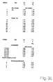
- Fig. 31 eine Tabelle mit bevorzugten Maßen für die Vorderteile der erfindungsgemäßen Schraubendreher-Einsätze.
- 1 to 3 are schematic longitudinal sections through three different sized front parts of a screwdriver insert according to the invention for Phillips screws, wherein the cross bars are not shown cut;
- 4 shows a schematic side view of a front part according to the invention, designed analogously to FIGS. 1 to 3;
- Figures 5 and 6 are sections taken along lines VV and VI-VI of Figure 4;
- 7 shows a partially sectioned side view of a screwdriver insert according to the invention with a front part according to FIGS. 4 to 6;
- 8 and 9 roughly schematically a pressing tool for producing a front part according to the invention according to Fig. 4;
- FIG. 10 is an enlarged side view of the front part of FIG. 4 in combination with an associated screw head shown in section; FIG.
- 11 is a view corresponding to FIG. 7 of a second embodiment of a screwdriver bit according to the invention;
- Fig. 12 is a section along the line XII-XII of Fig. 11;
- 13 to 16 are each a partially sectioned or uncut front view of three further embodiments of connection forms of the front part of hard metal with the drive part;
- 17 to 19 screwdriver inserts for Phillips screws of various sizes;
- 20 shows an exemplary embodiment of the screwdriver insert according to the invention, corresponding to FIG. 7, but with a convex anchoring element projecting from the drive part;
- Fig. 21 is a section taken along the line XXI-XXI;
- FIG. 22 shows a screwdriver insert corresponding to FIG. 17 for Phillips screws with a further embodiment of the anchoring element; FIG.
- Fig. 23 is a section along the line XXIII-XXIII;
- Fig. 24 is a section along the line XXIV-XXIV;
- FIG. 25 shows an embodiment analogous to FIG. 22, but with a front part for Pozidriv screws (PZ); FIG.
- 26 shows a partially, greatly enlarged longitudinal section through a front part of a screwdriver insert according to the invention for TORX® screws;
- Fig. 27 is a plan view (front view) of the screwdriver bit of Fig. 29;
- 28 shows a side view and front view of a screwdriver insert according to the invention for TORX® screws with outlet radius;
- 29 each a side view and front view (top view) of a screwdriver insert according to the invention for hexagonal screws with outlet radius;
- 30 is a side view and front view of a screwdriver insert according to the invention for Robertson screws with outlet radius. and
- Fig. 31 is a table of preferred dimensions for the front parts of the screwdriver bits according to the invention.
Fig. 1 zeigt ein Vorderteil 1 eines erfindungsgemäßen Schraubendreher-Einsatzes. Das Vorderteil 1 ist an seinem Vorderende mit einem Eindringabschnitt 2 in Form einer üblichen Kreuzspitze versehen, die zum Eindringen in das entsprechende Innenprofil einer Kreuzschlitzschraube dient. Die Kreuzspitze enthält vier kreuzförmig angeordnete Rippen oder Stege 3 mit Oberkanten 4, die nach vorn kegelförmig aufeinander zulaufen und an einem für die Zwecke der Erfindung unbedeutenden, abgeflachten Endabschnitt 5 enden. Zwischen den Stegen 3 sind Kreuzrillen oder -nuten mit ebenfalls bis zum Endabschnitt 5 konisch verlaufenden Nutenböden 6 angeordnet, die an der vom Endabschnitt 5 abgewandten Seite ab einer Stelle 7, die das rückwärtige Ende des Eindringabschnitts 2 definiert, radial nach außen gewölbt oder abgeschrägt verlaufen und dadurch einen nachfolgend als Auslauf 8 bezeichnetes Abschnitt bilden.Fig. 1 shows a
An den Auslauf 8 schließt sich nach rückwärts ein z. B. zylindrischer Basisabschnitt 9 an, der an einer rückwärtigen Stirnfläche 10 endet, die in der Regel senkrecht zu einer Mittel-oder Drehachse 11 des Vorderteils verläuft. Von der Stirnfläche 10 steht nach rückwärts noch ein Verankerungsabschnitt 12 in Form eines Zapfens ab, der einen im Vergleich zum Bauabschnitt 9 reduzierten Querschnitt besitzt, wobei der Eindringabschnitt 2, der Basisabschnitt 9 und der Verankerungsabschnitt 12 koaxial zur Achse 11 angeordnet sind. Diese Grundform des Vorderteils 1 ist bei allen Schraubendreher-Einsätzen der Erfindung im wesentlichen die gleiche, wobei jedoch die äußere Gestaltung und die Abmessungen vor allem der verschiedenen Abschnitte 2, 4 und 6 an das Innenprofil der jeweils zugeordneten Schraube und der Abschnitte 12 an die gewählte Verankerungsalt angepaßt sein müssen, wie weiter unten erläutert ist.At the
Fig. 2 zeigt ein zu Fig. 1 analoges Vorderteil 1 und dessen für die Erfindung wesentlichen Maße. Danach bezeichnet ein Maß L0 die Länge des Eindringabschnitts 2 zwischen dem Endabschnitt 5 und dem Auslauf 8, L1 die Länge des Vorderteils 1 zwischen dem Endabschnitt 5 und der Stirnfläche 10, LP die Profillänge, die sich aus der Summe der Länge L0 und der Länge LA des Auslaufs 8 ergibt, und LB die Länge des Basisabschnitts 9, so daß LP + LB = L1. Für die Länge LA des Auslaufs 8 folgt daraus LA = L1 - L0 - LB = LP - L0). Alle Längen werden dabei in Richtung der Längsachse 11 (Fig. 2) gemessen. Außerdem zeigt ein Vergleich der Fig. 1 bis 3, in denen gleiche Teile mit demselben Bezugszeichen versehen sind, daß diejenige Stelle 7, 7a bzw. 7b an der die konischen Bereiche der Nutenböden 6 des Eindringabschnitts 2 enden und in den Auslauf 8 übergehen, in Fig. 1 in gleicher Höbe mit den unteren Ender der Oberkanten 4 der Stege 3 liegt, während die entsprechende Stelle 7a bzw. 7b in Fig. 2 unterhalb und in Fig. 3 oberhalb des unteren Endes der Oberkanten 4 liegt. Das ist eine Folge davon, daß normalerweise sowohl ein Maß D1, das den Durchmesser des Vorderteils 1 am Ende der Länge L1, d. h. im Bereich des Basisabschnitts 9 bzw. der Stirnfläche 10 angibt, als auch die Kegelwinkel, unter denen die Oberkanten 4 der Stege 3 und die Nutenböden 6 verlaufen, durch Normen oder dgl. vorgegeben sind. Die Oberkanten 4 enden daher nach unten hin jeweils dort, wo sie einen gedachten Umfangszylinder des Basisabschnitts 9. schneiden. Schließlich bezeichnet d0 den Durchmesser am Ende der Länge LO, d. h. an den Stellen 7, 7a bzw. 7b.Fig. 2 shows an analogous to Fig. 1
Vorderteil 1 (Fig. 4 bis 6) und einem ebenfalls separat hergestellten Antriebsteil 14 (Fig. 7) zusammengesetzt, das z. B. zur Befestigung des Einsatzes im Futter eines Motorschraubers dient. Dabei wird das Vorderteil 1 aus Hartmetall, das Antriebsteil 14 dagegen aus einem für diese Zwecke üblichen Werkzeugstahl hergestellt. Zur koaxialen Verbindung dieser beiden Teile 1, 14 zu einem Schraubendreher-Einsatz (Fig. 7) ist das Antriebsteil 14 an einer dem Vorderteil 1 zugewandten Stirnseite mit einer in deren Oberfläche eingearbeiteten, mit ihrem Innenquerschnitt an den Außenquerschnitt des Verankerungsteils 12 angepaßten Ausnehmung 15 versehen. Die Verbindung erfolgt dann dadurch, daß das Verankerungsteil 12 in die Ausnehmung 15 eingeführt und in dieser derart verpreßt, verlötet oder auf andere Art befestigt wird, daß das Antriebsteil 14 die geforderten Drehmomente auf das Vorderteil 1 übertragen kann. Wie Fig. 7 zeigt, kann die Ausnehmung 15 in einem z. B. zylindrischen oder leicht konischen Übergangsabschnitt 16 ausgebildet sein, der sich an einen Abschnitt 17 mit üblichem Sechskant-Außenprofil des Antriebsteils 14 anschließt und einen bündigen Übergang vom Abschnitt 17 zum Basisabschnitt 9 bewirkt.Front part 1 (Fig. 4 to 6) and a likewise separately produced drive member 14 (Fig. 7) composed, the z. B. is used to attach the insert in the lining of a motor screwdriver. In this case, the
Die Herstellung des Vorderteils 1 erfolgt mit Hilfe eines in Fig. 8 und 9 schematisch angedeuteten Preßwerkzeugs 19. Dieses enthält eine Preßbuchse 20, die an einem Ende mit einer z. B. zylindrischen Aufnahmeöffnung 21 für einen z. B. ebenfalls zylindrischen Preßstempel 22 und am anderen Ende mit einer in sie eingesetzten Preßmatrize 23 versehen ist, die an einer der Aufnahmeöffnung 21 koaxial gegenüberliegenden Seite als Negativform 24 für das herzustellende Vorderteil 1, d. h. im Ausführungsbeispiel als Negativform für eine Kreuzspitze ausgebildet ist. Zwischen der Negativform 24 und der Aufnahmeöffnung 21 weist die Preßbuchse 20 einen Hohlraum 26 auf. Außerdem ist die Preßmatrize 20 mit einem zentralen Durchgang versehen, in den ein Auswerfer 25 eingesetzt ist. Der Preßstempel 22 ist an seiner der Preßmatrize 22 zugewandten Stirnfläche mit einer Ausnehmung 27 versehen, die als Negativform des Verankerungteils 12 ausgebildet ist.The preparation of the
Zur Herstellung des Vorderteils 1 wird zunächst bei eingeführtem und bis zur Preßmatrize 24 vorgeschobenen Auswerfer 25 der Hohlraum 26 mit dem gewünschten Hartmetallpulver gefüllt, wie in Fig. 8 durch das Bezugszeichen 28 angedeutet ist. Anschließend wird der Preßstempel 22 in die Aufnahmeöffnung 21 eingeführt und mit dem zur Verdichtung des Hartmetallpulvers 28 erforderlichen Druck in Richtung der Preßmatrize 23 vorgepreßt, wodurch das Hartmetallpulver 28 verdichtet und in die Form des Vorderteils 2 (Fig. 9) gebracht wird. Danach wird der Preßstempel 22 entfernt, der Auswerfer 25 vorgeschoben, um das Vorderteil 2 aus der Preßmatrize 22 und der Preßbuchse 20 auszustoßen, und das erhaltene Vorderteil 2 auf bei derartigen Preßverfahren übliche Weise z. B. bei 1100° C bis 1200° C gesintert: Die Hartmetallpulvermischung enthält z. B. Cobalt-, Molybdän-, und Wolframcarbid und ggf. Anteile an Eisen und führt durch den Preß- und Sintervorgang zu einem äußerst harten und verschleißfesten Vorderteil 2.To produce the
Durch die zweiteilige Ausbildung der erfindungsgemäßen Schraubendreher-Einsätze 2, 14 wird erreicht, daß die eigentliche Funktions- bzw. Wirkzone, die im Vorderteil 1 enthalten ist, mit einem vergleichsweise einfachen, kostengünstigen Verfahren hergestellt wird, bei dem aber dennoch optimale Preß-Verhältnisse erreicht werden. Nach der Verbindung des Vorderteils 1 mit dem Antriebsteil 14 entsteht dann ein Schraubendreher-Einsatz, der auch hohen Belastungen widersteht.Due to the two-part design of the screwdriver inserts 2, 14 according to the invention, it is achieved that the actual functional or active zone, which is contained in the
Zur Erzielung einer gleichmäßigen Druckverteilung und damit einer homogenen Gefügestruktur im Vorderteil 1 wird es im Rahmen der Erfindung für erforderlich gehalten, das Vorderteil 1 so klein wie möglich auszubilden, um im Werkzeug 19 möglichst geringe Reibungsverluste zu verursachen. Da die Form und die Größe des eigentlichen Eindringabschnitts 2 von der Innenprofilierung im Kopf der jeweils zugeordneten Schraube abhängt, wird zur Erreichung dieses Ziels von den folgenden Überlegungen ausgegangen:To achieve a uniform pressure distribution and thus a homogeneous microstructure in the
Zunächst ist klar, daß die oben erläuterten Abschnitte und Größen im Rahmen der Erfindung, wie sich aus der späteren Beschreibung ergibt, nicht nur für das Kreuzschlitz-System nach Fig. 1 bis 3, sondern entsprechend auch für andere Bit/Schrauben-Paarungen gelten. Hierzu zählen z. B. die Kreuzschlitz-Systeme nach Phillips und Pozidriv, die üblichen Sechskantsysteme, ferner die Mehrkant-, Vielzahn- oder Wellenformsysteme nach TORX® oder Vierkant-Robertson sowie verschiedene Sondersysteme wie z. B. Tri-Wing und Torque-Set.First of all, it is clear that the portions and sizes discussed above in the context of the invention, as will be apparent from the later description, apply not only to the Phillips system of FIGS. 1 to 3, but also to other bit / screw pairings. These include z. As the Phillips and Pozidriv Phillips systems, the usual hexagonal systems, further the TORX® or square Robertson polygonal, multi-tooth or waveform systems as well as various special systems such. B. Tri-Wing and Torque-Set.
Für die Bemessung der Eindringabschnitte 2 der Bits bzw. der zugehörigen Innenprofile der Schrauben gibt es z. B. DIN/ISO-Normen oder andere Normen und Vorschriften, die z. B. von den ursprünglichen Entwicklern der jeweiligen Profilsysteme vorgegeben wurden.For the dimensioning of the
Diese Normen und Vorschriften werden für die Zwecke der Erfindung übernommen, soweit dies für eine gute Funktion bzw. eine gute Paarung Bit/Schraube erforderlich ist. Dabei werden für Kreuzschlitz-Systeme die DIN-Normen 967, 7996 und 7997 und/oder EN-ISO 7045 bis 7047 zugrunde gelegt, nach denen die Schrauben der verschiedenen Gewindedurchmesser in Kreuzschlitzgrößen 0 bis 4 eingeteilt sind und zu jeder Größe Schrauben mit unterschiedlichen Köpfen und Innenprofilen und daher unterschiedlichen Eindringtiefen in diese gehören können.These standards and regulations are adopted for the purposes of the invention, as far as this is required for a good function or a good pairing bit / screw. It is based on the DIN standards 967, 7996 and 7997 and / or EN-ISO 7045 to 7047, according to which the screws of different thread diameters are divided into cross-slit sizes 0 to 4 and for each size screws with different heads and Internal profiles and therefore different penetration depths can belong in these.
Wichtig für die gute Passung von Kreuzschlitze und Innenprofil der Schraube ist es, daß die Kreuzspitze mit den Flanken der Stege 3 (Fig. 1) an den Flanken des Innenprofils der Schraube Flächenkontakt hat. Das tragende Profil der Kreuzspitze muß so lang sein, daß es in das Kreuzprofil der Schraube eintauchen kann, ohne daß etwa die Kreuzspitze an ihrem Auslauf 8, der nicht mehr der richtigen Kontur des Eindringabschnitts 2 entspricht, auf dem Rand des Kreuzschlitzprofils der Schraube aufsitzt. Dies ist schematisch in Fig. 10 angedeutet, die ein Vorderteil 1 gemäß Fig. 1 bis 7 zeigt, das in die profilierte Öffnung eines Schraubenkopfs 29 eintaucht, der eine Eindringtiefe T besitzt, die kleiner ist, als der Länge L0 des Eindringabschnitts 2 entspricht. Die Stelle 7, an der die Kreuznutenböden 6 in den Auslauf 8 übergehen, befindet sich dabei ausreichend weit außerhalb der Schraubenkopföffnung. Würde L0 < T gelten, würde der Eindringabschnitt 2 nur in einem Teil der Schraubenkopföffnung liegen, weil sich der Auslauf 8 auf den Schraubenkopf 29 auflegen würde. Außerdem hätte dies zur Folge, daß der gute Flächenkontakt zwischen den Eindringabschnitt 2 und den zugehörigen Flächen der Schraubenkopföffnung verloren ginge und der Einsatz mit etwas Spiel in der Schraube sitzen würde, was für die Übertragung hoher Drehmomente ungünstig ist. Bei L0 = T kann sich schließlich in Abhängigkeit von den jeweiligen Toleranzen ebenfalls der Fall L0 < T einstellen.
Bei dieser Festlegung wird andererseits selbstverständlich davon ausgegangen, daß die Profilmaße der Eindringabschnitte in dem zum Eindringen in die Schraube vorgesehenen Bereich im Querschnitt den festgelegten Normen in Zuordnung zum jeweiligen Kreuzschlitztyp und -Größe entsprechen.Important for the good fit of Phillips and inner profile of the screw is that the cross point with the flanks of the webs 3 (Fig. 1) on the flanks of the inner profile of the screw has surface contact. The supporting profile of the cross point must be so long that it can dive into the cross profile of the screw, without about the cross point at its
In this determination, on the other hand, it is understood, of course, that the profile dimensions of the penetrating portions in the area provided for penetration into the screw correspond in cross section to the specified standards in association with the respective cross-slot type and size.
Um zu einem für die Praxis brauchbaren Kompromiss zu gelangen, wird bei der Bemessung der Einsätze erfindungsgemäß die Länge L0 anhand desjenigen Schraubenkopfs einer der Profilgröße des Eindringabschnittes zugeordneten Schraubenserie bemessen, der nach der jeweiligen Norm oder sonstigen Vorschrift die größte Eindringtiefe T hat. Zunächst wird dazu von demjenigen Schraubentyp ausgegangen, durch deren Kopfform sich die größte Eindringtiefe T ergibt. Das sind im Fall von Kreuzschlitzschrauben z. B. Linsensenkschrauben nach EN-ISO 7047. Da bei allen anderen Schraubentypen die Eindringtiefe T deutlich kleiner ist, passen anhand der Linsensenkblechschrauben bemessene Einsätze auch auf die dasselbe Innenprofil aufweisenden Köpfe anderer Schrauben.In order to arrive at a practicable compromise in the design of the inserts according to the invention, the length L0 on the basis of that screw head one of Profile size of the Eindringabschnittes assigned screw series, which has the largest penetration depth T according to the relevant standard or other rule. First, it is assumed that the screw type, through whose head shape, the largest penetration depth T results. These are in the case of Phillips screws z. B. Lens countersunk screws according to EN-ISO 7047. As with all other types of screws, the penetration depth T is significantly smaller, measured on the basis of the lens sinker screws sized inserts also on the same inner profile having heads of other screws.
Gibt es zu irgendeiner Größe eines bestimmten Kreuzschlitzprofils Schrauben, die aufgrund unterschiedlicher Kopfformen zu unterschiedlichen Eindringtiefen T führen, wird zur Bemessung von L0 diejenige Schraube ausgewählt, die die größte Eindringtiefe T hat.If there are screws that lead to different penetration depths T due to different head shapes for any size of a particular cross-slot profile, the screw that has the greatest penetration depth T is selected to design L0.
Dies wird nachfolgend anhand eines konkreten Ausführungsbeispiels erläutert.This will be explained below with reference to a concrete embodiment.
Nach EN-ISO 7045 - 7047 (Typ Z, Pozidriv) können z. B. Linsensenkschrauben der Größe 2 mit Kreuzschlitz unterschiedlich genormte Eindringtiefen der Lehre haben, denen die Bereiche TMIN bis TMAX von 1,48/1,93 mm bis 2,9/3,35 mm zugeordnet sind. Erfindungsgemäß wird der größte vorkommende Bereich der größten Schraubenkopfform für die Bemessung von L0 herangezogen, indem L0 den Wert 3,35 mm erhält. Dadurch wird sichergestellt, daß das Vorderteil 1 in alle Schraubenköpfe mit voller Eindringtiefe T eintauchen kann. Ein Vorteil dieser Bemessungsweise von L0 besteht darin, daß L0 nicht größer gemacht wird, als für die gewünschte Funktion erforderlich ist.According to EN-ISO 7045 - 7047 (type Z, Pozidriv), z. B. countersunk square head screws with Phillips differently standardized penetration depths of the teaching, which the areas TMIN to TMAX of 1.48 / 1.93 mm to 2.9 / 3.35 mm are assigned. According to the invention, the largest occurring area of the largest screw head shape is used for the design of L0 by L0 is 3.35 mm. This ensures that the
Im Hinblick auf das Maß L1 wird erfindungsgemäß gefordert, daß es möglichst klein sein soll, um beim Preßvorgang die gewünschte gleichmäßige Druckverteilung zu gewährleisten. Dies wird erfindungsgemäß dadurch sichergestellt, daß L1 nicht größer als 2,5 · L0, vorzugsweise nicht größer als 2,2 · L0 und mit ganz besonderem Vorteil kleiner als 2,0 · L0 gewählt wird, was beim obigen Beispiel L1 = 8,5 mm bzw. 7,48 mm bzw. 6,80 mm entspricht. Dabei hängt die Größe von L1 bei Kreuzschlitzprofilen unter anderem davon ab, wie groß die Werte für LP und LB (Fig. 2) sein sollen. Im Hinblick auf LP hat sich als zweckmäßig erwiesen, den Auslauf 8 deutlich kleiner zu wählen, als dies bei herkömmlichen Bits möglich ist. Wird aber der Auslauf 8 zu klein gewählt, ergeben sich ungünstige Druckverteilungen beim Preßvorgang infolge des steilen Übergangs vom Basisabschnitt 9 zum Eindringabschnitt 2, während zu große Werte von LP die Gesamtlänge L 1 zu stark vergrößern würden. Für sich alleine betrachtet bedeutet eine kurze Profillänge LP, insbesondere bei Kreuzspitzen, daß die Gesamtoberfläche deutlich kleiner wird. Dadurch wird die Reibung beim Ausstoßen des Pressteiles aus der Matrize erheblich kleiner, zum anderen erhöht eine kurze Profillänge LP auch die Belastbarkeit. Als günstig gelten Verhältnisse von Lp/Lo im Bereich von ca. 1.25 bis 1.55. Im oben genannten Fall hat sich mit einer Länge LB von jenach Bitgröße um ca 0,8mm bis 1,5mm und höchstens 2,5 mm ein Wert LP von ca. 5,00 bis 5,25 mm als zweckmäßig erwiesen, was mit einem ausreichend großen Wert L1 = 6,00 bis 6,25 mm, d. h. L1 = 1,76 · L0 bis 1,84 · L0 zu einem kurzen und daher gut preßbaren Vorderteil 1 führt.With regard to the measure L1 is required according to the invention that it should be as small as possible to ensure the desired uniform pressure distribution during the pressing process. This is ensured according to the invention by choosing L1 not greater than 2.5 * L0, preferably not greater than 2.2 * L0, and with very particular advantage less than 2.0 * L0, which in the above example is L1 = 8.5 mm or 7.48 mm or 6.80 mm. Among other things, the size of L1 in cross-hatch profiles depends on how large the values for LP and LB should be (FIG. 2). With regard to LP has proved to be expedient to choose the
Für die drei anderen Größen 1, 3 und 4 nach EN-ISO 7045 - 7047 (Typ Z, Pozidriv) haben sich folgende Werte als zweckmäßig erwiesen:
- Größe 1:
- Hier liegt der Bereich ETMIN bis ETMAX bei 1,22
bis bis 2,08 für größere Schraubenköpfe. Erfindungsgemäß wird L0 = 2,1 mm, LP = 3,0 mm und L1 = 3,8 mm gewählt. - Größe 3:
- Hier liegt der Bereich ETMIN bis ETMAX bei 2,73
mm bis 3,18 mm. Erfindungsgemäß wird L0 = 4,4 mm, LP = 6,6 mm und L1 = 8,1 mm gewählt. - Größe 4:
- Hier liegt der Bereich ETMIN bis ETMAX bei 3,87
mm bis mm bis 6,05 mm für größere Schraubenköpfe. Erfindungsgemäß wird L0 = 6,6 mm LP = 8,8 mm und L1 = 10,3 mm gewählt.
- Size 1:
- Here, the range ETMIN to ETMAX is 1.22 to 1.47 mm for smaller and 1.83 to 2.08 for larger screw heads. According to the invention, L0 = 2.1 mm, LP = 3.0 mm and L1 = 3.8 mm are selected.
- Size 3:
- Here, the range ETMIN to ETMAX is 2.73 mm to 3.18 mm. According to the invention, L0 = 4.4 mm, LP = 6.6 mm and L1 = 8.1 mm are selected.
- Size 4:
- Here, the range ETMIN to ETMAX ranges from 3.87 mm to 4.32 mm for smaller and 5.6 mm to 6.05 mm for larger screw heads. According to the invention, L0 = 6.6 mm LP = 8.8 mm and L1 = 10.3 mm are selected.
Aus den obigen Werten ergibt sich, daß keiner der Werte für L1 größer als 2 - L0 mm ist und insbesondere für die kleineren Größen sehr kleine Werte für L1 erhalten werden können, selbst wenn L1 zu 2,5 · L0 bemessen wird. Ganz besonders bevorzugte Maße ergeben sich aus Fig. 31.It can be seen from the above values that none of the values for L1 is greater than 2 - L0 mm, and particularly for the smaller sizes, very small values for L1 can be obtained, even when L1 is rated at 2.5 · L0. Very particularly preferred dimensions are shown in FIG. 31.
Für andere Schraubenköpfe [z. B. Typ H (Phillips) nach EN-ISO 7045 - 7047] kann auf entsprechende Weise vorgegangen werden.For other screw heads [z. B. type H (Phillips) according to EN-ISO 7045 - 7047] can be proceeded in a similar manner.
Der Basisabschnitt 9 besteht aus einem kurzen, plattenförmigen Abschnitt, der hauptsächlich zur Anformung der Verankerungselemente 12 dient. Diese können aus konvexen, von der Stirnfläche 10 (Fig. 1) abstehenden oder aus konkaven, in die Stirnfläche 10 versenkten Formelementen bestehen. Anhand der Fig. 11 bis 24 werden nachfolgend einige Ausführungsbeispiele näher erläutert, bei denen die Vorderteile 1 im wesentlichen bis auf teilweise unterschiedliche Basisabschnitte dem Vorderteil 1 nach Fig. 1 bis 9 entsprechen. In analoger Weise entsprechen die Antriebsteile 14 im wesentlichen dem Antriebsteil 14 nach Fig. 7, weshalb jeweils nur die unterschiedlichen Teile mit anderen Bezugszeichen als bisher bezeichnet sind. Während, as Verankerungselement 12 nach Fig. 1 bis 9 ein Zylindrischer Zapfen ist, ist das Vorderteil 1 nach Fig. 11 und 12 mit einem Senkrecht von der anderen Stirnfläche der Basisabschnitts 9 abstehenden Verankerungselement 31 mit einem TORX- Profil versehen, das in eine Ausnehmung 32 des Antriebsteils 14 eingesetzt ist, die ein entsprechendes Innenprofil besitzt. Die feste Verbindung beider Teile 1,14 erfolgt z. B. durch Kleben, Löten, Verpressen od. dgl., wobei der unrunde Querschnitt der Verankerungselemente 31, 32 den Vorteil hat, daß durch Formschiuß eine drehfeste, das Übertragen hoher Drehmomente ermöglichende, Verbindung erzielt wird.The
Fig. 13 zeigt ein konkaves Verankerungselement 33 im Basisabschnitt 9 und ein entsprechendes, jedoch konvexes Verankerungselement 34 an Antriebsteil 14. Die Verbindung erfolgt z. B. durch Kleben oder Löten.FIG. 13 shows a
Fig. 14 zeigt zwei Verankerungselemente in Form ebener Flächen an der Unterseite des Basisabschnitts 9 bzw. an der Oberseite des Übergangsabschnitts 16 des Antriebsteils 14. Die beiden Verankerungsteile sind hier längs einer Grenzfläche 35 durch Schweißen fest miteinander verbunden.Fig. 14 shows two anchoring elements in the form of flat surfaces on the underside of the
Nach Fig. 15 ist das Vorderteil 1 mit einem Verankerungselement 36 in Form einer erhaben vom Basisabschnitt 9 abstehenden Keilrippe versehen, während ein Antriebsteil 37 an seiner dem Basisabschnitt 9 zugewandten Stirnfläche mit einem Verankerungselement 38 in Form einer entsprechenden, konkaven Keilnut versehen ist. Die Befestigung der beiden Verankerungselemente 36, 37 aneinander erfolgt durch Löten längs einer Lötnaht 39. Das Ausführungsbeispiel nach Fig. 15 unterscheidet sich außerdem dadurch von denen nach Fig. 7 bis 14, daß das Antriebsteil 37 zylindrisch ausgebildet ist.According to Fig. 15, the
Beim Ausführungsbeispiel nach Fig. 16 ist das zylindrische Antriebsteil 37 analog zu Fig. 14 durch Schweißen längs einer Schweißnaht 40 mit dem Vorderteil 1 verbunden. Im Gegensatz zu Fig. 7 bis 14 ist der Querschnitt des Antriebsteils 37 nach Fig. 13 und 14 etwas größer als der des Basisabschnitts 9 bzw. als der Durchmesser D1 in Fig. 2.In the embodiment according to FIG. 16, the
Fig. 17 und 18 zeigen im direkten Vergleich zwei erfindungsgemäße Schraubendreher-Einsätze, die sich im Bereich eines Basisabschnitts 9 bzw. 41 unterscheiden. Während der Basisabschnitt 9 in Fig. 17 wie in Fig. 1 bis 9 ausgebildet ist, weist der Basisabschnitt 41 im unmittelbaren Anschluß an einen Auslauf 42 eine sich radial erweiternde Zone 43 auf, die dann in eine dem Basisabschnitt 9 entsprechende Zone 44 übergeht. Dagegen unterscheidet sich das im direkten Vergleich mit Fig. 17 und 18 dargestellte Ausführungsbeispiel nach Fig. 19 dadurch von den Ausführungsbeispielen nach Fig. 7 bis 14, daß ein Antriebsteil 45 über einen Übergangsabschnitt 46 mit einem Basisabschnitt 47 eines Vorderteils 48 verbunden ist. Der Basisabschnitt 47 besitzt hier ein Maß D1 (Fig. 2), das im Gegensatz zu Fig. 7 größer als der Durchmesser des Sechskantabschnitts des Antriebsteils 45 ist, und der Übergangsabschnitt 46 dient in diesem Fall dazu, den kleineren Querschnitt des Sechskantabschnitts mit dem größeren Querschnitt des Basisabschnitts 47 zu verbinden. Das Verankerungselement ist hier beispielhaft so ausgeführt, wie zu Fig. 22 bis 24 beschrieben.FIGS. 17 and 18 show in a direct comparison two screwdriver inserts according to the invention, which differ in the region of a
Fig. 20 und 21 zeigen einen von der oberen Stirnseite des Antriebsteils 14 abstehendes Verankerungselement 48, das in einem entsprechenden, in die Stirnfläche des Basisabschnitts 9 eingearbeiteten Verankerungselement 49 in Form einer Ausnehmung steckt.FIGS. 20 and 21 show an anchoring
Gemäß Fig. 21 besitzen die Verankerungselemente 48 und 49 ein Bogenstern-Profil analog zu Fig. 12. Die Verbindung beider Verankerungselemente 48, 49 erfolgt z. B. durch Löten längs einer Lötnaht 50.21, the anchoring
Nach Fig. 22 bis 24 ist an dem Basisabschnitt 9 des Vorderteils 1 ein erhaben vorstehendes Verankerungselement 52 mit einem kreuzförmigen Profil angeformt, das in einem entsprechendem Verankerungselement 53 in Form eines Kreuzschlitzes steckt, der in der oberen Stirnfläche des Übergangsabschnitts 16 des Antriebsteils 14 ausgebildet ist. Die Befestigung erfolgt z. B. durch Kleben oder Löten. Diese Ausführungsform wird derzeit für die beste Variante der Verankerungselemente gehalten.Referring to FIGS. 22 to 24, a raised protruding anchoring
Fig. 25 zeigt schließlich ein Ausführungsbeispiel analog zu Fig. 17, bei dem ein Vorderteil 1a mit einem Eindringabschnitt 2a mit Pozidriv-Profil versehen, das wie in Fig. 22 bis 24 ausgeführt ist. Ein Basisabschnitt 9a ist mit einem vorstehenden Verankerungselement 12a versehen, das in ein entsprechendes Verankerungselement 15a in Form einer Ausnehmung ragt, die in die obere Stirnfläche des Übergangsabschnitts 16 des Antriebsteils 14 eingearbeitet ist. Die Verbindung der beiden Verankerungselemente 12a, 15a erfolgt durch Löten im Bereich der Kontaktflächen.Finally, FIG. 25 shows an exemplary embodiment analogous to FIG. 17, in which a front part 1a is provided with a
Im übrigen gilt für die Pozidriv-Einsätze (PZ) nach Fig. 25 im wesentlichen dasselbe wie für die anderen Kreuzschlitz-Einsätze (PH) nach Phillips. Wie Fig. 25 zeigt, ist L0 die Länge des Eindringabschnitts 2a, der sich bis zu einem Auslauf 8a erstreckt, während L1 die Gesamtlänge des Vorderteils 1a mit Ausnahme der Länge des Verankerungselements 12a ist. Auch für die Maße von L0 und L1 der Pozidriv-Einsätze gilt dasselbe wie für die der Phillips-Einsätze, d. h. es gilt L1 ≤ 2,5 · L0, vorzugsweise L1 ≤ 2,2 · L0 und mit ganz besonderen Vorteil L1 < 2 · L0, wobei L0 analog zur obigen Beschreibung ermittelt wird.Incidentally, the same applies to the Pozidriv inserts (PZ) of Fig. 25 as to the other Phillips (Ph) Phillips inserts. As shown in Fig. 25, L0 is the length of the penetrating
Ist aus irgendeinem Grund für eine Schraubengröße oder Schranbenkopfform nur ein einziger Bereich ETMIN bis ETMAX für die Eindringtiefe vorgegeben oder vorgeschrieben, kann L0 auch gleich dem Maß ETMAX zuzüglich eines kleinen Zuschlags zum Toleranzausgleich gewählt werden, da in diesem Fall die Länge L0 immer passend wäre.If, for some reason, only a single range ETMIN to ETMAX for the penetration depth is specified or specified for a screw size or cup form, L0 may also be chosen equal to ETMAX plus a small allowance for tolerance compensation, since in this case length L0 will always be would be suitable.
Im übrigen ist klar, daß die Länge der Verankerungselemente, in Richtung der Achse 11 (Fig. 2) gemessen, möglichst klein sein sollte, um die homogene Druckverteilung beim Preßvorgang nicht zu behindern. Da die Verankerungselemente jedoch auf der dem Preßstempel zugewandten Seite der Vorderteile 1, la angeordnet sind, ist ihre Länge weniger kritisch, als dies für die Längen L0 und L1 gilt. Abgesehen davon kann bei Bedarf vorgesehen werden, die Verankerungselemente in das Maß L1 einzubeziehen.Moreover, it is clear that the length of the anchoring elements, in the direction of the axis 11 (Fig. 2) measured, should be as small as possible, so as not to hinder the homogeneous pressure distribution during the pressing process. However, since the anchoring elements are arranged on the side of the
Was oben anhand von Schraubendreher-Einsätzen mit Kreuzschlitz-Profil erläutert wurde, gilt für Schraubendreher-Einsätze mit anderen Profilen entsprechend, z. B. für Innensechskant-, TORX® - und Robertson-Schrauben. Bei diesen Schraubendreher-Einsätzen haben die Eindringabschnitte ein in axialer Richtung im Querschnitt gleichmäßig - bei Robertson leicht konisch - verlaufendes Profil. Dabei geht das Profil mit gerundetem Auslauf in ein Basisteil über. Das hat den Vorteil, daß sich der Querschnitt der Hartmetallspitze (des Hartmetall-Funktionsteiles) in dem Bereich, in dem die Torsionskräfte bei Gebrauch wirksam werden, verstärkt. Die Verankerung im Antriebsteil erfolgt in gleicher Weise, wie oben ausführlich beschrieben wurde.What has been explained above with screwdriver inserts with cross-slot profile, applies to screwdriver inserts with other profiles accordingly, z. For hexagon socket, TORX® and Robertson screws. In these screwdriver inserts have the penetration sections in the axial direction in cross-section evenly - in Robertson slightly conical - extending profile. The profile with rounded outlet goes over into a base part. This has the advantage that the cross section of the hard metal tip (the hard metal functional part) in the area in which the torsional forces are effective in use reinforced. The anchoring in the drive part takes place in the same way as has been described in detail above.
Bei TORX® -Schrauben sind außerdem die minimalen Längen L0 des Eindringabschnitts durch Normen des Herstellers oder andere Vorschriften vorgegeben, die sich z. B. einem zugehörigen Datenblatt entnehmen lassen. Die Funktionslängen für die verschiedenen Profilgrößen werden daraus gegebenenfalls mit einem Zuschlag abgeleitet. Ähnlich wird bei anderen Profilen wie z. B. Sechskant- oder Robertson-Profilen vorgegangen. Dabei können die Eindringabschnitte mit Auslauf entsprechend dem längs eines Kreisbogens verlaufenden Auslauf 8,8a (z. B. Fig. 1, 25) in einen Basisabschnitt übergehen.For TORX® screws, the minimum lengths L0 of the penetration section are also specified by the manufacturer's standards or other regulations, such as: B. an associated data sheet. The function lengths for the different profile sizes are derived from this, if necessary with a surcharge. Similarly, in other profiles such. B. hexagonal or Robertson profiles. In this case, the penetration sections with outlet can pass into a base section in accordance with the
Die Anwendung der Erfindung auf TORX® - und andere Profile wird nachfolgend anhand der Fig. 26 bis 30 näher erläutert.The application of the invention to TORX® - and other profiles will be explained in more detail with reference to FIGS. 26 to 30.
Fig. 26 und 27 zeigen in Analogie zu Fig. 1 und 2 ein Vorderteil 58 eines erfindungsgemäßen, für TORX® -Schrauben bestimmten Schraubendreher-Einsatzes in einem stark vergrößerten Maßstab. Das Vorderteil 58 ist koaxial zu einer Längs- oder Drehachse 59 angeordnet und an seinem Vorderende mit einem Eindringabschnitt 60 versehen, der ein übliches TORX® -Profil aufweist, dessen wellenförmiger Verlauf sich insbesondere aus Fig. 27 ergibt, und der zum Eindringen in das entsprechende Innenprofil einer TORX®-Schraube dient. Das TORX® -Profil zeichnet sich durch in Umfangsrichtung aufeinander folgende, zur Achse 59 parallele Stege 61 und Nuten 62 (Fig. 27) mit gerundeten Kanten aus, die dem Profil längs eines gedachten Kreises einen wellenförmigen Verlauf geben. Das TORX® -Profil ist im ganzen Eindringabschnitt 60 in Richtung der Achse 59 gleich und endet an einem kegelförmigen, für die Zwecke der Erfindung unbedeutenden, abgeflachten Endabschnitt 63. An seiner vom Endabschnitt 63 abgewandten Rückseite sind die Nutenböden ab einer Stelle 64, die das rückwärtige Ende des Eindringabschnitts 60 definiert, radial nach außen gewölbt, wodurch analog zu den Ausläufen 8,8a ein Auslauf 65 entsteht, der an einem Basisabschnitt 66 endet, der im wesentlichen dem Basisabschnitt 9 nach Fig. 1 entspricht und eine rückwärtige Stirnfläche 67 aufweist, die in der Regel senkrecht zur Achse 59 verläuft. Von der Stirnfläche 67 steht nach rückwärts ein Verankerungselement 68 in einer Ausführungsform, wie in zu Fig. 22 bis 24 beschrieben,FIGS. 26 and 27 show, analogously to FIGS. 1 and 2, a
Die Grundform des Vorderteils 58 entspricht im wesentlichen der des Vorderteil 1 nach Fig. 1, weshalb ihm für die Zwecke der vorliegenden Erfindung dieselben Längen L0, L1, LP und LB sowie der Durchmesser D1 zugeordnet werden, wie dies oben anhand der Fig. 2 ausführlich erläutert wurde.The basic shape of the
Erfindungsgemäß wird ein Schraubendreher-Einsatz für TORX®-Schrauben gemäß Fig. 28 aus dem separat und einstückig hergestellten Vorderteil 58 und einem ebenfalls separat hergestellten Antriebsteil 69 zusammengesetzt, das z. B. in einem Abschnitt 70 ein übliches Sechskantprofil hat und analog zu Fig. 1 bis 27 mittels eines Übergangsab-schnitts 71 mit dem Vorderteil 58 verbunden ist. Der Übergangsabschnitt 71 ist dazu mit einem entsprechenden Verankerungselement 72 in Form einer in seiner vorderen Stirnfläche ausgebildeten Ausnehmung versehen. Die Verbindung der beiden Verankerungselemente 68, 72 erfolgt analog zu obigen Beschreibung durch Kleben, Schweißen, Löten oder durch sonstige Verbindungsverfahren.According to the invention, a screwdriver insert for TORX® screws according to FIG. 28 from the separately and integrally manufactured
Die Herstellung des Vorderteils 58 erfolgt analog zu den Kreuzspitz-Vorderteilen 1 aus einem Hartmetallpulver und mit Hilfe eines Preßwerkzeugs nach Fig. 8 und 9, dessen Preßbuchse 20 und gegebenenfalls Preßmatrize 23 entsprechend angepaßt werden.The production of the
Zur Sicherstellung einer gleichförmigen Druckverteilung beim Preßvorgang wird das Maß L0 wiederum möglichst kurz und vorzugsweise entsprechend denjenigen Emdringüefen T bemessen, die der Anbieter des jeweiligen TORX® -Systems in einem Datenblatt od. dgl. vorgibt. Dabei wird die Länge L0 vorzugsweise wenigstens gleich der vorgegebenen Eindringtiefe bemessen, wobei zweckmäßig noch eine Zugabe zum Toleranzausgleich hinzugefügt wird. Die Länge L1 bemißt sich dann analog zu den Kreuzspitzen zu maximal L1 = 2,5 · L0 vorzugsweise maximal L1 = 2,2 · L0 und mit ganz besonderem Vorteil zu L1 < 2,0 · L0. Das gilt unabhängig davon, ob für L0 die vorgeschriebene (minimale) Eindringtiefe T oder ein etwas größer oder ein etwas kleinerer Wert verwendet wird, weil sich für das Vorderteil 58 selbst bei voller Ausnutzung des Bereichs L1 = 2,5 · L0 nur sehr kurze, für die Anwendung des beschriebenen Preßverfahrens geeignete Werte ergeben.To ensure a uniform pressure distribution during the pressing process, the dimension L0 is again as short as possible and preferably measured according to those of the embrasures T which the supplier of the respective TORX® system specifies in a data sheet or the like. In this case, the length L0 is preferably dimensioned at least equal to the predetermined penetration depth, wherein an additional addition for tolerance compensation is expediently added. The length L1 is then measured analogously to the cross tips to a maximum of L1 = 2.5 · L0, preferably a maximum of L1 = 2.2 · L0 and with very particular advantage to L1 <2.0 · L0. This is true regardless of whether the prescribed (minimum) penetration depth T or a slightly greater or a slightly smaller value is used for L0, because for the
Nur beispielsweise wird in diesem Zusammenhang auf die TORX® -Systeme mit den Größen 15, 20, 30, 40 und 50 Bezug genommen, für die vom Hersteller bzw. Anbieter minimale Eindringtiefen 2,16 mm, 2,29 mm, 3,18 mm, 3,30 mm und 4,57 mm vorgeschrieben werden, die ein ausreichend tiefes Eindringen der TORX® -Profile in die Schraubenköpfe und eine Übertragung der geforderten Drehmomente garantieren sollen. Erfindungsgemäß wird für diese fünf Größen die Länge L0 z. B. zu 2,40 mm, 2,50 mm, 3,50 mm, 3,65 mm und 5,05 mm und die Länge L1 zu 4,1 mm, 4,8 mm, 5,8 mm, 6,95 mm und 8,35 mm gewählt, in welchem Fall die Ll-Werte weit unter dem zweifachen des LO-Wertes liegen. Ganz besonders bevorzugte Maße ergeben sich aus Fig. 31.For example, reference is made to TORX® systems of
Hinsichtlich der Werte LP, LB und D1 gelten dieselben Überlegungen, wie sie oben anhand der Kreuzspitz-Einsätze erläutert wurden.With regard to the values LP, LB and D1, the same considerations apply as explained above with reference to the Kreuzspitz inserts.
Fig. 29 zeigt einen Schraubendreher-Einsatz für Schrauben mit Sechskant-Innenprofilen. Dieser unterscheidet sich von dem Schraubendreher-Einsatz nach Fig. 26 bis 28 nur dadurch, daß er ein Vorderteil 74 mit einem Eindringabschnitt 75 aufweist, der mit einem üblichen Sechskantprofil versehen ist. Im übrigen sind die verschiedenen Teile dieselben, weshalb in Fig. 29 gleiche Teile mit denselben Bezugszeichen wie in Fig. 26 bis 28 vorgesehen sind. Ein Auslauf ist mit dem Bezugszeichen 76 versehen. Auch für die Größen L0, L1 usw. gilt dasselbe wie bei Schraubendreher-Einsätzen für TORX® -Schrauben, und zwar auch im Hinblick auf die Bemessung dieser Größen zur Erzielung einer optimalen Gefügestruktur beim Preßvorgang nach Fig. 8 und 9.Fig. 29 shows a screwdriver insert for screws with hexagon internal profiles. This differs from the screwdriver insert according to FIGS. 26 to 28 only in that it has a
Fig. 30 zeigt einen zweiteilig hergestellten Schraubendreher-Einsatz mit einem ein Robertson-Profil aufweisenden Vorderteil 77, das einen Eindringabschnitt 78 mit einem nach Art eines Vierkants ausgebildeten, quadratischen, aus der Draufsicht ersichtlichen Profil aufweist. Das Vorderteil 77 ist längs eines bogenförmig radial nach außen gewölbten Auslaufs 79 mit einem Basisabschnitt verbunden, der an seiner Rückseite mit dem Verankerungselement 68 versehen ist, das in das als Ausnehmung ausgebildete Verankerungselement 72 des vorzugsweise aus normalem Werkzeugstahl hergestellten Antriebsteils 69 gesteckt und in diesem befestigt wird. Da die Anordnung bis auf den Eindringabschnitt 78 dieselbe wie in Fig. 28 und 29 ist, sind zur Vereinfachung der Darstellung wiederum gleiche Teile mit denselben Bezugszeichen versehen. Dabei ist klar, daß z. B. der Übergangsabschnitt 71 in Abhängigkeit von der Form des jeweiligen Eindringabschnitts 60, 75 bzw. 78 unterschiedliche Formen aufweisen kann.30 shows a two-part screwdriver insert having a Robertson-
Im Hinblick auf die Maße L0, L1 usw. (vgl. Fig. 30) gilt dasselbe wie für die TORX® - und Sechskant-Einsätze (vgl. auch Fig. 31).With regard to the dimensions L0, L1, etc. (see Fig. 30), the same applies as for the TORX® and hexagonal inserts (see also Fig. 31).
Gegenüber einteiligen, z. B. durch Spritzgießen hergestellten Schraubendreher-Einsätzen (z. B. DE 42 41 005 A1) hat die beschriebene zweiteilige Ausführung den Vorteil, daß das kleine Vorderteil aus Hartmetall preßtechnisch und maßlich genauer herstellbar ist und in der Ebene der höchsten Torsionsspannung, d. h. in der Ebene der vorderen Stirnseite des Antriebsteiles, keine Einkerbungen aufweist, die durch Kerbspannung die Bruchgefahr erhöhen. Als solche Einkerbungen sind z. B. die unmittelbaren Übergänge der Kreuzstege in die Stirnfläche bei der einteiligen Ausführung nach DE 42 41 005 A1 anzusehen.Opposite one-piece, z. As described by injection molding screwdriver inserts (eg,
Die für die Kreuzschlitzprofile gewonnen Erkenntnisse gelten im Prinzip auch für andere Profile. Preßtechnisch sind allerdings Profile mit einem in axialer Richtung gleichmäßig verlaufendem Querschnitt günstiger als die Kreuzschlitzprofile. Deshalb ist bei den gleichmäßig verlaufenden Profilen ein größeres Verhältnis Länge zu Durchmesser zulässig, zumal der Durchmesser der Auswerferstempel mit rundem Querschnitt ausgeführt und/oder nahezu gleich dem Profildurchmesser sein kann. Die Einleitungsverhältnisse der Auswerferkraft in den Preßling sind daher günstiger.In principle, the insights gained for the cross-slit profiles also apply to other profiles. Pressing technology, however, profiles are cheaper with a uniform cross-section in the axial direction than the cross slot profiles. Therefore, in the evenly extending profiles, a greater length to diameter ratio is permissible, especially as the diameter of the ejector punches can be made with a round cross-section and / or can be almost equal to the profile diameter. The discharge conditions of Auswerferkraft in the compact are therefore cheaper.
Erfindungsgemäß wirkt sich dies dahingehend aus, daß bei Kreuzschlitzprofilen das Verhältnis L1/d0 = (Fig. 2) etwa 1,0 bis 1,2 betragen sollte, d. h. L1 und d0 etwa gleich groß sein sollten. Bei TORX® -Profilen mit Auslauf haben sich Verhältnisse L1/d0 (Fig. 26, 27) von etwa 0,9 bis 1,4 als zweckmäßig erwiesen, d. h. hier kann L1 im allgemeinen etwas größer als d0 sein. Bei Sechskantprofilen mit Auslauf liegen günstige Verhältnisse von L1 (Fig. 29) zu d0 bei ca. 1,4 bis 1,9, wo d0 das Eckmaß gemäß Fig. 29 in Millimetern ist: Bei Robertson-Profilen ergeben sich günstige Vorderteile mit L1/d0 (Fig. 30) von ca. 1,3 bis 1,5, wobei d0 wiederum das Eckmaß in Millimetern ist (Fig. 30).According to the invention will be affected to the extent that should be about 1.0 to 1.2 at Phillips profiles, the ratio L1 / d =0 (Fig. 2), ie L1 and d0 should be approximately the same size. Ratios L1 / d0 (Figures 26, 27) of about 0.9 to 1.4 have been found to be useful in TORX® spouted outlets, ie, L1 may generally be slightly larger than d0. In the case of hexagonal profiles with outlet, favorable ratios of L1 (FIG. 29) to d0 are approximately 1.4 to 1.9, where d0 is the angular dimension according to FIG. 29 in millimeters. Robertson profiles result in favorable front parts with L1 / d0 (Figure 30) from about 1.3 to 1.5, where d0 is again the girth in millimeters (Figure 30).
Die Erfindung ist nicht auf die beschriebenen Ausführungsbeispiele beschränkt, die auf vielfache Weise abgewandelt werden können. Dies gilt zunächst für die Form der Verankerungselemente, wobei auch die Anwendung von zwei oder mehr Verankerungselementen pro Bit denkbar wäre, wenn diese z. B. als mehrere Zapfen ausgebildet würden.The invention is not limited to the described embodiments, which can be modified in many ways. This applies initially to the shape of the anchoring elements, whereby the application of two or more anchoring elements per bit would be conceivable if these z. B. would be formed as a plurality of pins.
Weiter können die beschriebenen Größen L0, L1, d0 usw. anders bemessen werden, als oben beispielhaft angegeben ist. Insbesondere die Verhältnisse Länge zu Durchmesser sollten dabei stets so gewählt werden, daß sich möglichst kleine Umfangs- bzw. Berührungsflächen mit dem Preßwerkzeug ergeben, damit günstige Reibungsverhältnisse und kleine Auswerferkräfte erhalten werden. Weiter ist es möglich, für die Bemessung von L0 nicht die jeweils absolut größte vorkommende Eindringtiefe zugrunde zu legen. Vielmehr könnte hierfür auch z. B. der größte TMAX/TMIN-Bereich verwendet und die Länge L0 so gewählt werden, daß sie einem Wert entspricht, der etwa in der Mitte dieses Bereichs liegt. Dann dringen die Eindringabschnitte bei den größten Schrauben zwar nicht voll, aber dennoch ausreichend tief in die Ausnehmungen der Schraubenköpfe ein, um einen guten Sitz zu erzielen. Welche Dimensionierung im Einzelfall besonders günstig ist, läßt sich leicht anhand der obigen Erläuterungen sowohl durch Berechnungen als auch durch Versuche ermitteln. Dabei zeigt sich, daß das Verhältnis L1/d0 vorzugsweise durchweg kleiner als 2,2 und mit besonderem Vorteil kleiner als 2,0 sein sollte. Bei Einsätzen mit Auslauf haben sich sogar Verhältnisse von L1/d0, die kleiner als 1,5 sind, als besonders vorteilhaft erwiesen, wobei die Größe d0 durch den jeweils zugeordneten Schraubenkopf bestimnit ist. Weiter ist die erfindungsgemäße geringe Länge L1 nicht nur bei durch Pressen und unmittelbar nachfolgendes Sintern, sondern auch bei durch Spritzgießen hergestellten Vorderteilen vorteilhaft. Wie beim Pressen ist nämlich auch beim Spritzgießen meistens eine Entformung mittels eines Auswerfers erwünscht und daher eine Verkleinerung des Entformungswiderstands durch Reduzierung der Länge zweckmäßig. Zur Förderung des Spritzgießvorgangs wird der Hartmetall-Pulvermischung ein Anteil an thermoplastischem Fließmittel (z. B. Wachs oder Kunststoff) zugegeben, das dem Rohling vor dem Sintern wilder entzogen wird. Für die Vergleichmäßigung der Gefügestruktur der Einsätze hat sich außerdem die gewählte Korngrößenzusammensetzung der Hartmetall-Pulvermischung als wichtig erwiesen. Besonders vorteilhaft sind dabei Kornabstufungen in der Mischung von 0,5 µm bis 8 µm. Schließlich versteht sich, daß die verschiedenen Merkmale und Größen auch in anderen als den beschriebenen und dargestellten Kombinationen angewendet werden können.Further, the described quantities L0, L1, d0, etc. can be dimensioned differently than exemplified above. In particular, the ratios of length to diameter should always be chosen so that the smallest possible circumferential or contact surfaces arise with the pressing tool, so favorable friction conditions and small Auswerferkräfte be obtained. Furthermore, it is not possible to base the design of L0 on the absolutely largest occurring penetration depth. Rather, this could also z. For example, the largest TMAX / TMIN range is used and the length L0 is chosen to be a value that is approximately in the middle of that range. Then penetrate the penetration of the largest screws, although not fully, but still sufficiently deep into the recesses of the screw heads to achieve a good fit. Which dimensioning is particularly favorable in the individual case can easily be determined from the above explanations both by calculations and by tests. It turns out that the ratio L1 / d0 should preferably be less than 2.2 and with particular advantage less than 2.0. For inserts with spout even ratios of L1 / d0, which are smaller than 1.5, have proven to be particularly advantageous, the size d0 is bestimnit by the respective associated screw head. Furthermore, the short length L1 according to the invention is advantageous not only in the case of pressing and immediately following sintering, but also in front parts produced by injection molding. As in the pressing process, demoulding by means of an ejector is usually also desired in injection molding, and therefore a reduction of the demolding resistance by reducing the length is expedient. To promote the injection molding process, a proportion of thermoplastic flux (eg wax or plastic) is added to the cemented carbide powder mixture, which is removed from the blank more savagely before sintering. To even out the microstructure of the inserts, the selected grain size composition of the cemented carbide powder mixture has also proved to be important. Grain gradations in the mixture of 0.5 μm to 8 μm are particularly advantageous. Finally, it should be understood that the various features and sizes may be applied in combinations other than those described and illustrated.
Claims (12)
- Screwdriver bit having a drive section (14, 37, 45, 69) and a front section (1, 1a, 58, 74, 77) of length (L1) which is manufactured by moulding or by injection-moulding and subsequently sintering a hard metal powder (28) and which has a profiled penetrating section (2, 2a, 60, 75, 78) with a profile length (LP), and on its rear side a base section (9, 9a, 41, 47, 66) secured to the drive section (14, 37, 45, 69) and of length (LB),characterised in that the groove bases of the penetrating section (2, 2a, 60, 75, 78) are connected to the base section (9, 41, 47, 60) by a continuation (8, 8a, 42, 65, 76, 79) which is determined during moulding to avoid unfavourable pressure distributions and in each case is curved radially outwards, wherein- a length (LA) of the continuation measured in the direction of the longitudinal axis arises from the difference between the profile length (LP) and the length (LO) of the groove bases (6) measured in the direction of the longitudinal axis (11) as far as the continuation,- a diameter or width across corners (dO) of the penetrating section is measured in a plane perpendicular to the longitudinal axis (11) which lies at the end of the length (LO) and contains a point (7, 7a or 7b) at which the groove bases (6) merge into the continuation,- the size ratio of (L1) to (LO) is between 1.00 and 2.5,- the size ratio of (L1) to (dO) is between 0.9 and 2.2, and- the length (LB) of the base section is 2.5 mm at the most.
- Screwdriver bit according to claim 1,characterised in that the base section (9, 41, 47, 66) has a length (LB) of 0.5 mm to 2.5 mm.
- Screwdriver bit according to claim 1 or 2,characterised in that the penetrating section (2, 2a, 60, 75, 78) has a cross-tip profile, a TORX profile, a hexagonal profile or a Robertson profile and its length (LO), measured up to the continuation (8, 8a, 42, 65, 76, 79), if an associated screw size contains heads (29) having different required or desired penetrating depths (T), is selected as a function of the respectively largest minimum and maximum penetrating depths (T) for that screw size.
- Screwdriver bit according to one of claims 1 to 3,characterised in that the hard metal powder mixture (28) has a grain size of between 0.5 µm and 8 µm.
- Screwdriver bit according to one of claims 1 to 4,characterised in that the front section (1, 1a, 58, 74, 77) and the drive section (14, 37, 45, 69) are interconnected by means of bonding, soldering, pressing or welding.
- Screwdriver bit according to one of claims 1 to 5,characterised in that the facing end surfaces of the front section (1, 1a, 58, 74, 77) and of the drive section (14, 37, 45, 69) are provided with anchoring elements (12, 31 to 34, 36, 38, 48, 49, 52, 53, 68, 72) which engage with each other.
- Screwdriver bit according to claim 6,characterised in that the anchoring elements (31 to 34, 36, 38, 48, 49, 52, 53, 68, 72) fix the front section (1, 1a, 58, 74, 77) and the drive section (14, 37, 45, 69) so that they cannot be turned relative to one another due to engaging with each other in an interlocking manner.
- Screwdriver bit according to one of claims 6 or 7,characterised in that the anchoring elements (31 to 34, 36, 38, 48, 49, 52, 53, 56, 68, 72) have non-circular cross-sections.
- Screwdriver bit according to one of claims 6 to 8,characterised in that the anchoring elements comprise a portion (31, 36, 52) protruding from an end surface of the front section (1) and a recess (32, 37, 53) formed in an end surface of the drive section (14).
- Screwdriver bit according to one of claims 6 to 8,characterised in that the anchoring elements comprise a portion (34, 38) protruding from an end surface of the drive section (14) and a recess (33, 49) formed in an end surface of the front section (1, 1a).
- Screwdriver bit according to one or more of claims 1 to 10,characterised in that the anchoring element and the recesses are so matched to one another in respect of form and dimensions that a fixed force-locking and/or interlocking connection for transmitting torques which coaxially centres the two parts is produced by pressing the two parts together.
- Screwdriver bit according to one of claims 1 to 11,characterised in that the front section (1, 1a, 1b, 58, 74, 77) is produced by compression moulding.
Applications Claiming Priority (3)
| Application Number | Priority Date | Filing Date | Title |
|---|---|---|---|
| DE10010311 | 2000-03-06 | ||
| DE10010311 | 2000-03-06 | ||
| PCT/DE2001/000852WO2001066312A1 (en) | 2000-03-06 | 2001-03-06 | Screwdriver insets |
Publications (2)
| Publication Number | Publication Date |
|---|---|
| EP1175284A1 EP1175284A1 (en) | 2002-01-30 |
| EP1175284B1true EP1175284B1 (en) | 2006-08-16 |
Family
ID=7633331
Family Applications (1)
| Application Number | Title | Priority Date | Filing Date |
|---|---|---|---|
| EP01923507AExpired - LifetimeEP1175284B1 (en) | 2000-03-06 | 2001-03-06 | Screwdriver insets |
Country Status (7)
| Country | Link |
|---|---|
| US (2) | US20020129680A1 (en) |
| EP (1) | EP1175284B1 (en) |
| AT (1) | ATE336334T1 (en) |
| AU (1) | AU5027601A (en) |
| DE (2) | DE10190814D2 (en) |
| ES (1) | ES2270999T3 (en) |
| WO (1) | WO2001066312A1 (en) |
Families Citing this family (51)
| Publication number | Priority date | Publication date | Assignee | Title |
|---|---|---|---|---|
| EP1175284B1 (en) | 2000-03-06 | 2006-08-16 | Felo-Werkzeugfabrik Holland-Letz Gmbh | Screwdriver insets |
| US20040099106A1 (en)* | 2000-06-27 | 2004-05-27 | Martin Strauch | Screw tool and production method thereof |
| EP1422027B1 (en)* | 2002-11-22 | 2007-07-18 | Felo-Werkzeugfabrik Holland-Letz Gmbh | Screw driving tool, in particular screwdriver bit |
| DE20304246U1 (en) | 2003-03-14 | 2003-05-22 | Felo-Werkzeugfabrik Holland-Letz GmbH, 35279 Neustadt | Screwdriver insert, has penetration section with reduced length for cooperating with internal profile in screw |
| DE10362089B4 (en)* | 2003-10-21 | 2009-12-31 | Felo-Werkzeugfabrik Holland-Letz Gmbh | Screwdriver socket |
| US20050227772A1 (en)* | 2004-04-13 | 2005-10-13 | Edward Kletecka | Powdered metal multi-lobular tooling and method of fabrication |
| US8739660B2 (en)* | 2006-04-24 | 2014-06-03 | Ttapdrive As | Screw head and tool for use therewith |
| GB2437537A (en)* | 2006-04-24 | 2007-10-31 | Jone Edland | Screw head with hexalobular recess and corresponding tool |
| DE102007041574A1 (en)* | 2007-09-01 | 2009-03-05 | Wera-Werk Hermann Werner Gmbh & Co. Kg | Double-ended screwdriver bit, has hexagonal driving profiles joined by thinner intermediate section of reduced hardness |
| CN102271870A (en) | 2008-11-07 | 2011-12-07 | 米沃奇电动工具公司 | Tool bit |
| USD623036S1 (en) | 2008-11-07 | 2010-09-07 | Milwaukee Electric Tool Corporation | Insert bit |
| USD628456S1 (en)* | 2009-04-20 | 2010-12-07 | Jin-Tsai Lai | Tool bit |
| USD616280S1 (en)* | 2009-06-27 | 2010-05-25 | Cheng-Wei Su | Tool bit |
| USD614931S1 (en)* | 2009-06-27 | 2010-05-04 | Cheng-Wei Su | Tool bit |
| USD615380S1 (en)* | 2009-09-09 | 2010-05-11 | Cheng-Wei Su | Tool bit |
| USD711719S1 (en) | 2009-11-06 | 2014-08-26 | Milwaukee Electric Tool Corporation | Tool bit |
| US20110283842A1 (en)* | 2010-05-21 | 2011-11-24 | Rote Mate Industry Co., Ltd. | Screwdriver bit structure |
| US9132534B2 (en)* | 2010-05-21 | 2015-09-15 | Rote Mate Industry Co., Ltd | Screwdriver bit |
| USD653517S1 (en)* | 2010-12-09 | 2012-02-07 | Ibt Holdings, Llc | Tool bit |
| USD653096S1 (en)* | 2010-12-20 | 2012-01-31 | Ibt Holdings, Llc | Tool bit |
| USD645329S1 (en)* | 2011-01-26 | 2011-09-20 | Hsu Shao-Hsien | Tool bit |
| TW201309431A (en)* | 2011-08-16 | 2013-03-01 | Meeng Gang Entpr Co Ltd | Fabrication method of screwdriver bit |
| US9067307B2 (en)* | 2012-12-05 | 2015-06-30 | Burton Kozak | Hexa-lobed head bit |
| US9010223B2 (en)* | 2013-02-06 | 2015-04-21 | New Way Tools Co., Ltd. | Tool bit |
| EP2986418A4 (en)* | 2013-04-16 | 2016-12-21 | Univ Northeastern | UNIVERSAL SCREWDRIVER |
| TW201420284A (en)* | 2013-09-06 | 2014-06-01 | Great Metal Production Co Ltd E | Structure and manufacturing method for screwdriver driving portion |
| US9339918B2 (en)* | 2013-12-11 | 2016-05-17 | Hsiu-Hua Chang | Identifiable tool |
| US10022845B2 (en)* | 2014-01-16 | 2018-07-17 | Milwaukee Electric Tool Corporation | Tool bit |
| US11154969B2 (en) | 2016-04-27 | 2021-10-26 | Grip Holdings Llc | Fastener extractor device |
| TWI533977B (en)* | 2014-12-10 | 2016-05-21 | Convenient for small space operations | |
| US11897099B2 (en) | 2018-09-19 | 2024-02-13 | Grip Holdings Llc | Fastener extractor and dislodging tool apparatus |
| US12403574B2 (en) | 2016-04-27 | 2025-09-02 | Grip Holdings Llc | Fastener extractor device |
| US11590637B2 (en) | 2017-04-27 | 2023-02-28 | Grip Holdings Llc | Methods and apparatuses for extracting and dislodging fasteners |
| US12023786B2 (en) | 2017-02-15 | 2024-07-02 | Grip Holdings Llc | Multi-directional driver bit |
| EP3571016B1 (en)* | 2017-03-23 | 2021-08-11 | Grip Holdings LLC | Multi-grip socket bit |
| US11701757B2 (en) | 2018-09-19 | 2023-07-18 | Grip Holdings Llc | Anti-slip fastener remover tool |
| US11602828B2 (en) | 2019-07-30 | 2023-03-14 | Grip Holdings Llc | Multi-grip screw apparatus |
| US12434360B2 (en) | 2017-03-23 | 2025-10-07 | Grip Holdings Llc | Advanced holding apparatus |
| USD966063S1 (en) | 2018-03-07 | 2022-10-11 | Grip Holdings Llc | Socket |
| US12337449B2 (en) | 2017-07-14 | 2025-06-24 | Grip Holdings Llc | Foreign object removal socket adapter |
| US11638987B2 (en)* | 2017-12-01 | 2023-05-02 | Milwaukee Electric Tool Corporation | Wear resistant tool bit |
| US11161234B2 (en) | 2018-03-15 | 2021-11-02 | Grip Holdings Llc | Tool holding apparatus |
| USD921468S1 (en) | 2018-08-10 | 2021-06-08 | Milwaukee Electric Tool Corporation | Driver bit |
| EP3807050A4 (en)* | 2018-08-21 | 2021-08-18 | Grip Holdings LLC | ADVANCED HOLDING DEVICE |
| EP3953108B1 (en) | 2019-04-12 | 2023-06-07 | Grip Holdings LLC | Anti-slip multidirectional fastener remover tool |
| US11759918B2 (en) | 2019-05-09 | 2023-09-19 | Grip Holdings Llc | Anti-slip torque tool with integrated engagement features |
| US11541516B2 (en)* | 2019-09-25 | 2023-01-03 | Snap-On Incorporated | Fastener retention and anti-camout tool bit |
| USD889224S1 (en) | 2019-12-20 | 2020-07-07 | Grip Holdings Llc | Equal torque hex bit |
| CN115066318B (en) | 2020-02-13 | 2024-05-28 | 米沃奇电动工具公司 | Tool bit with bi-metallic tip |
| USD1042059S1 (en) | 2022-02-25 | 2024-09-17 | Grip Holdings Llc | Percussion drive |
| USD1026602S1 (en) | 2022-03-17 | 2024-05-14 | Grip Holdings Llc | Selectable twist tool |
Family Cites Families (20)
| Publication number | Priority date | Publication date | Assignee | Title |
|---|---|---|---|---|
| DE7044913U (en)* | Stanley Works | Tool in the shape of a long shaft with a working point | ||
| US1977845A (en)* | 1928-12-22 | 1934-10-23 | Cleveland Twist Drill Co | Cutting and forming tool, implement, and the like and method of making same |
| US2366682A (en)* | 1942-04-01 | 1945-01-02 | Champion Inc | Screw driver bit |
| US2804894A (en)* | 1954-08-20 | 1957-09-03 | Cornwall & Patterson Company | Screw driver |
| US3393722A (en)* | 1966-07-19 | 1968-07-23 | George W. Windham | Bit end of tool |
| GB1455003A (en)* | 1973-03-15 | 1976-11-10 | Iskra M | Screwdrivers and screws for use therewith |
| US3888144A (en)* | 1974-02-08 | 1975-06-10 | Joseph D Parsons | Screw and driver |
| DE2534729A1 (en)* | 1974-08-17 | 1976-02-26 | Marian Iskra | SCREWDRIVER BLADE |
| FR2469250A1 (en)* | 1979-11-12 | 1981-05-22 | Defougeres Pierre | Tapered cruciform bit for screw-driver - has identical tapered wings at ninety degree intervals and is in one pressed piece |
| DE8813187U1 (en) | 1988-10-20 | 1988-12-08 | Felo Holland-Letz GmbH & Co KG, 3577 Neustadt | Screwdriver blade or screwdriver bit |
| DE4121839C2 (en)* | 1991-07-02 | 2003-01-09 | Werner Hermann Wera Werke | Tool with torque transmitting work surfaces and method for manufacturing the same |
| DE9202273U1 (en) | 1992-02-21 | 1993-06-17 | Wera-Werk Hermann Werner Gmbh & Co, 5600 Wuppertal | A screwing tool designed in the form of a screwdriver or screwdriver bit |
| DE4241005A1 (en)* | 1992-12-05 | 1994-06-09 | Schmidt Ulrich Ush Schraubwerk | Screwdriver insert bit with insertable active zone - which is adjacent positively to stem or short intermediate part |
| DE4300446C2 (en)* | 1992-12-22 | 2002-12-19 | Werner Hermann Wera Werke | Screwing tools, especially screwdriver bits |
| DE4243608C2 (en)* | 1992-12-22 | 2000-10-19 | Werner Hermann Wera Werke | Tool |
| US5868047A (en)* | 1994-01-26 | 1999-02-09 | Vermont American Corporation | Insert bit for use with a powered screwdriver |
| JP4638562B2 (en)* | 1996-12-10 | 2011-02-23 | パーデュー・リサーチ・ファウンデーション | Biological material derived from vertebrate liver tissue |
| US6185771B1 (en)* | 1999-12-06 | 2001-02-13 | John E. Trusty, Sr. | Pocket tool having slidably extensible pliers |
| EP1175284B1 (en) | 2000-03-06 | 2006-08-16 | Felo-Werkzeugfabrik Holland-Letz Gmbh | Screwdriver insets |
| US6352011B1 (en)* | 2000-08-11 | 2002-03-05 | Fruehm Hermann | Two-ended screwdriver bits |
- 2001
- 2001-03-06EPEP01923507Apatent/EP1175284B1/ennot_activeExpired - Lifetime
- 2001-03-06AUAU50276/01Apatent/AU5027601A/ennot_activeAbandoned
- 2001-03-06ATAT01923507Tpatent/ATE336334T1/ennot_activeIP Right Cessation
- 2001-03-06ESES01923507Tpatent/ES2270999T3/ennot_activeExpired - Lifetime
- 2001-03-06WOPCT/DE2001/000852patent/WO2001066312A1/enactiveIP Right Grant
- 2001-03-06DEDE10190814Tpatent/DE10190814D2/ennot_activeExpired - Fee Related
- 2001-03-06DEDE50110735Tpatent/DE50110735D1/ennot_activeExpired - Lifetime
- 2001-11-06USUS09/992,900patent/US20020129680A1/ennot_activeAbandoned
- 2003
- 2003-05-19USUS10/441,135patent/US7168348B2/ennot_activeExpired - Fee Related
Also Published As
| Publication number | Publication date |
|---|---|
| US20020129680A1 (en) | 2002-09-19 |
| WO2001066312A1 (en) | 2001-09-13 |
| US7168348B2 (en) | 2007-01-30 |
| EP1175284A1 (en) | 2002-01-30 |
| ES2270999T3 (en) | 2007-04-16 |
| ATE336334T1 (en) | 2006-09-15 |
| DE50110735D1 (en) | 2006-09-28 |
| DE10190814D2 (en) | 2003-03-27 |
| AU5027601A (en) | 2001-09-17 |
| US20040139829A1 (en) | 2004-07-22 |
Similar Documents
| Publication | Publication Date | Title |
|---|---|---|
| EP1175284B1 (en) | Screwdriver insets | |
| EP1743724B1 (en) | Method for producing a form-locking coupling between a tool insert and a tool insert holder on a rotating tool | |
| DE60012766T2 (en) | DRILL, DRILLING TIP AND THEIR MANUFACTURE | |
| EP2318166B1 (en) | Tool for machining a work piece | |
| WO2007076968A1 (en) | Screw nut, method of production thereof and corresponding tool | |
| DE60012784T2 (en) | DISCONTINUING TOOL | |
| WO1997017153A1 (en) | Drilling tool with replaceable bit | |
| EP1616652A2 (en) | Tool for the finish forming without chip removal of a preformed thread, method of manufacturing such a tool and method of producing a thread | |
| EP3416575B1 (en) | Device for bone fixation | |
| DE202011050277U1 (en) | drilling | |
| EP1725355B1 (en) | Method for the production of hollow elements, hollow element and progressive composite tool | |
| WO2011023428A1 (en) | Tool | |
| EP1147841A1 (en) | Cutting insert and tool for milling | |
| DE20204848U1 (en) | Interchangeable drill tip and drilling tool arrangement | |
| DE3126355C2 (en) | Drilling screw | |
| DE10144990A1 (en) | Composite bit for screwdriver is manufactured from two segments made respectively of hard pressed and sintered metal and steel | |
| WO2005089973A1 (en) | Flow moulding drilling method with simultaneous thread and flow moulding drilling tool for carrying out said method | |
| WO2012163897A1 (en) | Drill | |
| DE19650453B4 (en) | A method of manufacturing an assembly nut and assembling nut made by the method | |
| DE3044001C2 (en) | ||
| EP1422027B1 (en) | Screw driving tool, in particular screwdriver bit | |
| WO2010034324A1 (en) | Threaded nut, method and tool for producing the same | |
| WO2007025679A1 (en) | Tool for machining workpieces | |
| EP2174739B1 (en) | Method for producing a driller, in particular a stone driller | |
| DE102005009030B4 (en) | Cutting tool, especially for micro and precision mold making |
Legal Events
| Date | Code | Title | Description |
|---|---|---|---|
| PUAI | Public reference made under article 153(3) epc to a published international application that has entered the european phase | Free format text:ORIGINAL CODE: 0009012 | |
| 17P | Request for examination filed | Effective date:20010926 | |
| AK | Designated contracting states | Kind code of ref document:A1 Designated state(s):AT BE CH CY DE DK ES FI FR GB GR IE IT LI LU MC NL PT SE TR | |
| AX | Request for extension of the european patent | Free format text:AL;LT;LV;MK;RO;SI | |
| 17Q | First examination report despatched | Effective date:20030310 | |
| GRAP | Despatch of communication of intention to grant a patent | Free format text:ORIGINAL CODE: EPIDOSNIGR1 | |
| GRAS | Grant fee paid | Free format text:ORIGINAL CODE: EPIDOSNIGR3 | |
| GRAA | (expected) grant | Free format text:ORIGINAL CODE: 0009210 | |
| AK | Designated contracting states | Kind code of ref document:B1 Designated state(s):AT BE CH CY DE DK ES FI FR GB GR IE IT LI LU MC NL PT SE TR | |
| PG25 | Lapsed in a contracting state [announced via postgrant information from national office to epo] | Ref country code:IT Free format text:LAPSE BECAUSE OF FAILURE TO SUBMIT A TRANSLATION OF THE DESCRIPTION OR TO PAY THE FEE WITHIN THE PRESCRIBED TIME-LIMIT;WARNING: LAPSES OF ITALIAN PATENTS WITH EFFECTIVE DATE BEFORE 2007 MAY HAVE OCCURRED AT ANY TIME BEFORE 2007. THE CORRECT EFFECTIVE DATE MAY BE DIFFERENT FROM THE ONE RECORDED. Effective date:20060816 Ref country code:FI Free format text:LAPSE BECAUSE OF FAILURE TO SUBMIT A TRANSLATION OF THE DESCRIPTION OR TO PAY THE FEE WITHIN THE PRESCRIBED TIME-LIMIT Effective date:20060816 Ref country code:IE Free format text:LAPSE BECAUSE OF FAILURE TO SUBMIT A TRANSLATION OF THE DESCRIPTION OR TO PAY THE FEE WITHIN THE PRESCRIBED TIME-LIMIT Effective date:20060816 Ref country code:NL Free format text:LAPSE BECAUSE OF FAILURE TO SUBMIT A TRANSLATION OF THE DESCRIPTION OR TO PAY THE FEE WITHIN THE PRESCRIBED TIME-LIMIT Effective date:20060816 | |
| REG | Reference to a national code | Ref country code:GB Ref legal event code:FG4D Free format text:NOT ENGLISH | |
| REG | Reference to a national code | Ref country code:CH Ref legal event code:EP | |
| REG | Reference to a national code | Ref country code:IE Ref legal event code:FG4D Free format text:LANGUAGE OF EP DOCUMENT: GERMAN | |
| REF | Corresponds to: | Ref document number:50110735 Country of ref document:DE Date of ref document:20060928 Kind code of ref document:P | |
| REG | Reference to a national code | Ref country code:CH Ref legal event code:NV Representative=s name:E. BLUM & CO. PATENTANWAELTE | |
| PG25 | Lapsed in a contracting state [announced via postgrant information from national office to epo] | Ref country code:DK Free format text:LAPSE BECAUSE OF FAILURE TO SUBMIT A TRANSLATION OF THE DESCRIPTION OR TO PAY THE FEE WITHIN THE PRESCRIBED TIME-LIMIT Effective date:20061116 Ref country code:SE Free format text:LAPSE BECAUSE OF FAILURE TO SUBMIT A TRANSLATION OF THE DESCRIPTION OR TO PAY THE FEE WITHIN THE PRESCRIBED TIME-LIMIT Effective date:20061116 | |
| GBT | Gb: translation of ep patent filed (gb section 77(6)(a)/1977) | Effective date:20061108 | |
| PG25 | Lapsed in a contracting state [announced via postgrant information from national office to epo] | Ref country code:PT Free format text:LAPSE BECAUSE OF FAILURE TO SUBMIT A TRANSLATION OF THE DESCRIPTION OR TO PAY THE FEE WITHIN THE PRESCRIBED TIME-LIMIT Effective date:20070116 | |
| NLV1 | Nl: lapsed or annulled due to failure to fulfill the requirements of art. 29p and 29m of the patents act | ||
| ET | Fr: translation filed | ||
| REG | Reference to a national code | Ref country code:IE Ref legal event code:FD4D | |
| REG | Reference to a national code | Ref country code:ES Ref legal event code:FG2A Ref document number:2270999 Country of ref document:ES Kind code of ref document:T3 | |
| PLBE | No opposition filed within time limit | Free format text:ORIGINAL CODE: 0009261 | |
| STAA | Information on the status of an ep patent application or granted ep patent | Free format text:STATUS: NO OPPOSITION FILED WITHIN TIME LIMIT | |
| 26N | No opposition filed | Effective date:20070518 | |
| REG | Reference to a national code | Ref country code:CH Ref legal event code:PFA Owner name:FELO-WERKZEUGFABRIK HOLLAND-LETZ GMBH Free format text:FELO-WERKZEUGFABRIK HOLLAND-LETZ GMBH#EMIL-ROESSLER-STRASSE 59#35279 NEUSTADT (DE) -TRANSFER TO- FELO-WERKZEUGFABRIK HOLLAND-LETZ GMBH#EMIL-ROESSLER-STRASSE 59#35279 NEUSTADT (DE) | |
| PG25 | Lapsed in a contracting state [announced via postgrant information from national office to epo] | Ref country code:MC Free format text:LAPSE BECAUSE OF NON-PAYMENT OF DUE FEES Effective date:20070331 | |
| PG25 | Lapsed in a contracting state [announced via postgrant information from national office to epo] | Ref country code:GR Free format text:LAPSE BECAUSE OF FAILURE TO SUBMIT A TRANSLATION OF THE DESCRIPTION OR TO PAY THE FEE WITHIN THE PRESCRIBED TIME-LIMIT Effective date:20061117 | |
| PG25 | Lapsed in a contracting state [announced via postgrant information from national office to epo] | Ref country code:CY Free format text:LAPSE BECAUSE OF FAILURE TO SUBMIT A TRANSLATION OF THE DESCRIPTION OR TO PAY THE FEE WITHIN THE PRESCRIBED TIME-LIMIT Effective date:20060816 Ref country code:LU Free format text:LAPSE BECAUSE OF NON-PAYMENT OF DUE FEES Effective date:20070306 | |
| PG25 | Lapsed in a contracting state [announced via postgrant information from national office to epo] | Ref country code:TR Free format text:LAPSE BECAUSE OF FAILURE TO SUBMIT A TRANSLATION OF THE DESCRIPTION OR TO PAY THE FEE WITHIN THE PRESCRIBED TIME-LIMIT Effective date:20060816 | |
| PGFP | Annual fee paid to national office [announced via postgrant information from national office to epo] | Ref country code:AT Payment date:20100930 Year of fee payment:10 | |
| PG25 | Lapsed in a contracting state [announced via postgrant information from national office to epo] | Ref country code:AT Free format text:LAPSE BECAUSE OF NON-PAYMENT OF DUE FEES Effective date:20110306 | |
| REG | Reference to a national code | Ref country code:DE Ref legal event code:R082 Ref document number:50110735 Country of ref document:DE Representative=s name:REHBERG HUEPPE + PARTNER, DE Ref country code:DE Ref legal event code:R082 Ref document number:50110735 Country of ref document:DE Representative=s name:REHBERG HUEPPE + PARTNER PATENTANWAELTE PARTG , DE | |
| REG | Reference to a national code | Ref country code:FR Ref legal event code:PLFP Year of fee payment:16 | |
| REG | Reference to a national code | Ref country code:FR Ref legal event code:PLFP Year of fee payment:17 | |
| PGFP | Annual fee paid to national office [announced via postgrant information from national office to epo] | Ref country code:CH Payment date:20170327 Year of fee payment:17 Ref country code:FR Payment date:20170323 Year of fee payment:17 Ref country code:DE Payment date:20170201 Year of fee payment:17 | |
| PGFP | Annual fee paid to national office [announced via postgrant information from national office to epo] | Ref country code:GB Payment date:20170327 Year of fee payment:17 Ref country code:BE Payment date:20170323 Year of fee payment:17 | |
| PGFP | Annual fee paid to national office [announced via postgrant information from national office to epo] | Ref country code:ES Payment date:20170323 Year of fee payment:17 Ref country code:IT Payment date:20170323 Year of fee payment:17 | |
| REG | Reference to a national code | Ref country code:DE Ref legal event code:R231 Ref document number:50110735 Country of ref document:DE | |
| PG25 | Lapsed in a contracting state [announced via postgrant information from national office to epo] | Ref country code:DE Free format text:LAPSE BECAUSE OF THE APPLICANT RENOUNCES Effective date:20171221 | |
| REG | Reference to a national code | Ref country code:CH Ref legal event code:PL | |
| GBPC | Gb: european patent ceased through non-payment of renewal fee | Effective date:20180306 | |
| REG | Reference to a national code | Ref country code:BE Ref legal event code:MM Effective date:20180331 | |
| PG25 | Lapsed in a contracting state [announced via postgrant information from national office to epo] | Ref country code:GB Free format text:LAPSE BECAUSE OF NON-PAYMENT OF DUE FEES Effective date:20180306 Ref country code:IT Free format text:LAPSE BECAUSE OF NON-PAYMENT OF DUE FEES Effective date:20180306 Ref country code:CH Free format text:LAPSE BECAUSE OF NON-PAYMENT OF DUE FEES Effective date:20180331 Ref country code:BE Free format text:LAPSE BECAUSE OF NON-PAYMENT OF DUE FEES Effective date:20180331 Ref country code:LI Free format text:LAPSE BECAUSE OF NON-PAYMENT OF DUE FEES Effective date:20180331 | |
| PG25 | Lapsed in a contracting state [announced via postgrant information from national office to epo] | Ref country code:FR Free format text:LAPSE BECAUSE OF NON-PAYMENT OF DUE FEES Effective date:20180331 | |
| REG | Reference to a national code | Ref country code:ES Ref legal event code:FD2A Effective date:20190904 | |
| PG25 | Lapsed in a contracting state [announced via postgrant information from national office to epo] | Ref country code:ES Free format text:LAPSE BECAUSE OF NON-PAYMENT OF DUE FEES Effective date:20180307 |