EP1171232B1 - Fluids manipulation device with format conversion - Google Patents
Fluids manipulation device with format conversionDownload PDFInfo
- Publication number
- EP1171232B1 EP1171232B1EP00920538AEP00920538AEP1171232B1EP 1171232 B1EP1171232 B1EP 1171232B1EP 00920538 AEP00920538 AEP 00920538AEP 00920538 AEP00920538 AEP 00920538AEP 1171232 B1EP1171232 B1EP 1171232B1
- Authority
- EP
- European Patent Office
- Prior art keywords
- fluid
- substrate
- pattern
- management apparatus
- dosing head
- Prior art date
- Legal status (The legal status is an assumption and is not a legal conclusion. Google has not performed a legal analysis and makes no representation as to the accuracy of the status listed.)
- Expired - Lifetime
Links
- 239000012530fluidSubstances0.000titleclaimsabstractdescription90
- 238000006243chemical reactionMethods0.000titledescription9
- 239000000758substrateSubstances0.000claimsabstractdescription63
- 238000000018DNA microarrayMethods0.000claimsdescription17
- 229910052710siliconInorganic materials0.000claimsdescription7
- 239000010703siliconSubstances0.000claimsdescription7
- 229920000642polymerPolymers0.000claimsdescription4
- 239000011521glassSubstances0.000claimsdescription3
- 239000000919ceramicSubstances0.000claimsdescription2
- 239000002184metalSubstances0.000claimsdescription2
- 150000001875compoundsChemical class0.000claims1
- 239000007788liquidSubstances0.000description47
- 238000000034methodMethods0.000description21
- 230000001133accelerationEffects0.000description15
- 238000005452bendingMethods0.000description10
- XUIMIQQOPSSXEZ-UHFFFAOYSA-NSiliconChemical compound[Si]XUIMIQQOPSSXEZ-UHFFFAOYSA-N0.000description6
- 239000000126substanceSubstances0.000description5
- 238000004519manufacturing processMethods0.000description3
- 239000000243solutionSubstances0.000description3
- 229910000831SteelInorganic materials0.000description2
- 201000010099diseaseDiseases0.000description2
- 208000037265diseases, disorders, signs and symptomsDiseases0.000description2
- 238000005516engineering processMethods0.000description2
- 239000004744fabricSubstances0.000description2
- 238000001746injection mouldingMethods0.000description2
- 239000000178monomerSubstances0.000description2
- 230000010355oscillationEffects0.000description2
- 239000010959steelSubstances0.000description2
- 208000026350Inborn Genetic diseaseDiseases0.000description1
- 241001465754MetazoaSpecies0.000description1
- 239000004480active ingredientSubstances0.000description1
- 239000012491analyteSubstances0.000description1
- 230000009286beneficial effectEffects0.000description1
- 239000012876carrier materialSubstances0.000description1
- 239000003153chemical reaction reagentSubstances0.000description1
- 239000011248coating agentSubstances0.000description1
- 238000000576coating methodMethods0.000description1
- 239000002131composite materialSubstances0.000description1
- 238000002508contact lithographyMethods0.000description1
- 238000011109contaminationMethods0.000description1
- 238000003745diagnosisMethods0.000description1
- 239000003814drugSubstances0.000description1
- 230000000694effectsEffects0.000description1
- 230000005686electrostatic fieldEffects0.000description1
- 238000001917fluorescence detectionMethods0.000description1
- 230000009395genetic defectEffects0.000description1
- 208000016361genetic diseaseDiseases0.000description1
- 230000005484gravityEffects0.000description1
- 230000002209hydrophobic effectEffects0.000description1
- 239000004615ingredientSubstances0.000description1
- 238000001459lithographyMethods0.000description1
- 238000002493microarrayMethods0.000description1
- 238000004377microelectronicMethods0.000description1
- 239000000203mixtureSubstances0.000description1
- 150000007523nucleic acidsChemical class0.000description1
- 102000039446nucleic acidsHuman genes0.000description1
- 108020004707nucleic acidsProteins0.000description1
- 238000012856packingMethods0.000description1
- 230000000284resting effectEffects0.000description1
- 238000010189synthetic methodMethods0.000description1
Images


Classifications
- B—PERFORMING OPERATIONS; TRANSPORTING
- B01—PHYSICAL OR CHEMICAL PROCESSES OR APPARATUS IN GENERAL
- B01L—CHEMICAL OR PHYSICAL LABORATORY APPARATUS FOR GENERAL USE
- B01L3/00—Containers or dishes for laboratory use, e.g. laboratory glassware; Droppers
- B01L3/02—Burettes; Pipettes
- B01L3/0241—Drop counters; Drop formers
- B01L3/0268—Drop counters; Drop formers using pulse dispensing or spraying, eg. inkjet type, piezo actuated ejection of droplets from capillaries
- B—PERFORMING OPERATIONS; TRANSPORTING
- B01—PHYSICAL OR CHEMICAL PROCESSES OR APPARATUS IN GENERAL
- B01J—CHEMICAL OR PHYSICAL PROCESSES, e.g. CATALYSIS OR COLLOID CHEMISTRY; THEIR RELEVANT APPARATUS
- B01J19/00—Chemical, physical or physico-chemical processes in general; Their relevant apparatus
- B01J19/0046—Sequential or parallel reactions, e.g. for the synthesis of polypeptides or polynucleotides; Apparatus and devices for combinatorial chemistry or for making molecular arrays
- F—MECHANICAL ENGINEERING; LIGHTING; HEATING; WEAPONS; BLASTING
- F04—POSITIVE - DISPLACEMENT MACHINES FOR LIQUIDS; PUMPS FOR LIQUIDS OR ELASTIC FLUIDS
- F04B—POSITIVE-DISPLACEMENT MACHINES FOR LIQUIDS; PUMPS
- F04B19/00—Machines or pumps having pertinent characteristics not provided for in, or of interest apart from, groups F04B1/00 - F04B17/00
- F04B19/006—Micropumps
- G—PHYSICS
- G01—MEASURING; TESTING
- G01N—INVESTIGATING OR ANALYSING MATERIALS BY DETERMINING THEIR CHEMICAL OR PHYSICAL PROPERTIES
- G01N35/00—Automatic analysis not limited to methods or materials provided for in any single one of groups G01N1/00 - G01N33/00; Handling materials therefor
- G01N35/10—Devices for transferring samples or any liquids to, in, or from, the analysis apparatus, e.g. suction devices, injection devices
- G01N35/1065—Multiple transfer devices
- G01N35/1067—Multiple transfer devices for transfer to or from containers having different spacing
- B—PERFORMING OPERATIONS; TRANSPORTING
- B01—PHYSICAL OR CHEMICAL PROCESSES OR APPARATUS IN GENERAL
- B01J—CHEMICAL OR PHYSICAL PROCESSES, e.g. CATALYSIS OR COLLOID CHEMISTRY; THEIR RELEVANT APPARATUS
- B01J2219/00—Chemical, physical or physico-chemical processes in general; Their relevant apparatus
- B01J2219/00274—Sequential or parallel reactions; Apparatus and devices for combinatorial chemistry or for making arrays; Chemical library technology
- B01J2219/00277—Apparatus
- B01J2219/00351—Means for dispensing and evacuation of reagents
- B01J2219/00378—Piezoelectric or ink jet dispensers
- B—PERFORMING OPERATIONS; TRANSPORTING
- B01—PHYSICAL OR CHEMICAL PROCESSES OR APPARATUS IN GENERAL
- B01J—CHEMICAL OR PHYSICAL PROCESSES, e.g. CATALYSIS OR COLLOID CHEMISTRY; THEIR RELEVANT APPARATUS
- B01J2219/00—Chemical, physical or physico-chemical processes in general; Their relevant apparatus
- B01J2219/00274—Sequential or parallel reactions; Apparatus and devices for combinatorial chemistry or for making arrays; Chemical library technology
- B01J2219/00277—Apparatus
- B01J2219/00497—Features relating to the solid phase supports
- B01J2219/00527—Sheets
- B—PERFORMING OPERATIONS; TRANSPORTING
- B01—PHYSICAL OR CHEMICAL PROCESSES OR APPARATUS IN GENERAL
- B01J—CHEMICAL OR PHYSICAL PROCESSES, e.g. CATALYSIS OR COLLOID CHEMISTRY; THEIR RELEVANT APPARATUS
- B01J2219/00—Chemical, physical or physico-chemical processes in general; Their relevant apparatus
- B01J2219/00274—Sequential or parallel reactions; Apparatus and devices for combinatorial chemistry or for making arrays; Chemical library technology
- B01J2219/00583—Features relative to the processes being carried out
- B01J2219/00603—Making arrays on substantially continuous surfaces
- B01J2219/00605—Making arrays on substantially continuous surfaces the compounds being directly bound or immobilised to solid supports
- B—PERFORMING OPERATIONS; TRANSPORTING
- B01—PHYSICAL OR CHEMICAL PROCESSES OR APPARATUS IN GENERAL
- B01J—CHEMICAL OR PHYSICAL PROCESSES, e.g. CATALYSIS OR COLLOID CHEMISTRY; THEIR RELEVANT APPARATUS
- B01J2219/00—Chemical, physical or physico-chemical processes in general; Their relevant apparatus
- B01J2219/00274—Sequential or parallel reactions; Apparatus and devices for combinatorial chemistry or for making arrays; Chemical library technology
- B01J2219/00583—Features relative to the processes being carried out
- B01J2219/00603—Making arrays on substantially continuous surfaces
- B01J2219/00659—Two-dimensional arrays
- C—CHEMISTRY; METALLURGY
- C40—COMBINATORIAL TECHNOLOGY
- C40B—COMBINATORIAL CHEMISTRY; LIBRARIES, e.g. CHEMICAL LIBRARIES
- C40B60/00—Apparatus specially adapted for use in combinatorial chemistry or with libraries
- C40B60/14—Apparatus specially adapted for use in combinatorial chemistry or with libraries for creating libraries
- G—PHYSICS
- G01—MEASURING; TESTING
- G01N—INVESTIGATING OR ANALYSING MATERIALS BY DETERMINING THEIR CHEMICAL OR PHYSICAL PROPERTIES
- G01N35/00—Automatic analysis not limited to methods or materials provided for in any single one of groups G01N1/00 - G01N33/00; Handling materials therefor
- G01N35/10—Devices for transferring samples or any liquids to, in, or from, the analysis apparatus, e.g. suction devices, injection devices
- G01N2035/1027—General features of the devices
- G01N2035/1034—Transferring microquantities of liquid
- G01N2035/1041—Ink-jet like dispensers
- G—PHYSICS
- G01—MEASURING; TESTING
- G01N—INVESTIGATING OR ANALYSING MATERIALS BY DETERMINING THEIR CHEMICAL OR PHYSICAL PROPERTIES
- G01N35/00—Automatic analysis not limited to methods or materials provided for in any single one of groups G01N1/00 - G01N33/00; Handling materials therefor
- G01N35/10—Devices for transferring samples or any liquids to, in, or from, the analysis apparatus, e.g. suction devices, injection devices
- G01N35/1065—Multiple transfer devices
- G01N35/1067—Multiple transfer devices for transfer to or from containers having different spacing
- G01N2035/1069—Multiple transfer devices for transfer to or from containers having different spacing by adjusting the spacing between multiple probes of a single transferring head
- Y—GENERAL TAGGING OF NEW TECHNOLOGICAL DEVELOPMENTS; GENERAL TAGGING OF CROSS-SECTIONAL TECHNOLOGIES SPANNING OVER SEVERAL SECTIONS OF THE IPC; TECHNICAL SUBJECTS COVERED BY FORMER USPC CROSS-REFERENCE ART COLLECTIONS [XRACs] AND DIGESTS
- Y10—TECHNICAL SUBJECTS COVERED BY FORMER USPC
- Y10T—TECHNICAL SUBJECTS COVERED BY FORMER US CLASSIFICATION
- Y10T436/00—Chemistry: analytical and immunological testing
- Y10T436/25—Chemistry: analytical and immunological testing including sample preparation
- Y10T436/2575—Volumetric liquid transfer
Definitions
- the present inventionrelates to a fluid handling device, which is a format conversion between one A plurality of fluid inlets and a plurality of fluid outlets provides, for example, for use in a Dosing head is suitable.
- the fluid handling device according to the inventionis, for example advantageous in the dosing head of a device for applying at least one microdroplet to a substrate usable with a plurality of microdroplets can be applied to a substrate.
- the inventionFluid handling device suitable to the production of so-called biochips, in which a majority different analytes applied to a substrate is about different substances in an unknown sample demonstrate to be used.
- the present one Inventionsuitable for a format conversion between To implement microtiter plates with different grid dimensions.
- biochipswill be used in the future Food in terms of a variety of possible, genetically engineered to investigate changed components.
- biochipscan be used in the field of application to be the exact one in genetically caused diseases Identify genetic defects in order to find the ideal strategy for Derive treatment of the disease.
- the biochips that can be used for such applicationsusually consist of a carrier material, i.e. one Substrate on which a variety of different substances in the form of a grid.
- a carrier materiali.e. one Substrate on which a variety of different substances in the form of a grid.
- the grid spacing in the arrayis between 100 ⁇ m and 1,000 microns.
- the variety of different substances that as so-called analytesare referred to on a biochip ranges from a few different ones depending on the application Fabrics up to some 100,000 different fabrics per substrate. With each of these different analytes can be a specific substance in an unknown sample be detected.
- the first methodis called "contact printing", with this method a bundle of steel capillaries is used inside with different analytes are filled. This bundle of steel capillaries is on the Stamped substrate. When lifting the bundle they remain Analytes adhere to the substrate in the form of microdroplets. With this method, however, the quality of the print pattern very strong due to the action of capillary forces determined and therefore depends on a variety of critical Parameters, such as quality and coating the surface of the substrate, the exact geometry of the Nozzle and especially of the media used. Is next to it the process is very susceptible to contamination of the Substrate and the nozzles. This procedure just described is suitable for a variety of analytes of a few 100 per substrate.
- the So-called "spotting"are usually so-called microdispensers used that is capable of similar to ink printers are single microdroplets of a liquid on one corresponding control command towards a substrate shoot. Such a process is called “drop-on-demand” designated.
- microdispensersare from some companies commercially available.
- the advantage with this procedureis that the analytes are non-contact on a substrate can be applied, the influence of capillary forces is meaningless.
- the limiting element hereis the actuators as well as media logistics, which are not to the desired extent are miniaturizable.
- WO-A-93/09668describes processes for forming polymers with different monomer sequences on a single one Known substrate in which over a plurality of channels, formed in a channel block, monomers to selected ones Regions are brought to polymers on these regions to synthesize.
- the channel blocksChannels on that open to the outside in a surface are and which have an inlet and an outlet, which in the opposite surface of the channel block are formed, exhibit.
- a desired reagentis supplied via the inlet opening delivered to the duct while to the outlet opening a vacuum pump is connected.
- WO-A-97/45730relates to methods and devices to deliver solutions to an array of cells.
- an array of cells on a substrateeducated.
- Another substratehas recesses and with the microchannels connected to the recesses, which enable to deliver a fluid into the recesses.
- the cellswill now introduced into the recesses, whereupon solutions through the channels in the recesses to the To treat cells.
- the microchannelsare with microcapillary tubes connected, for example using solutions can be fed to a microtiter plate.
- the present inventionhas for its object a To provide fluid handling device that allows Microdroplets from a plurality of fluid reservoirs in a predetermined pattern inexpensively and precisely on a Apply substrate.
- the present inventionthus provides a fluid handling device which is a format conversion between one first pattern and a second pattern.
- the automatic Format conversionis achieved through the arrangement of the fluid inputs, the fluid outlets and through the media lines causes.
- the substrate of the fluid handling device according to the inventionis preferably micromechanical, i.e. for example through silicon processing techniques or injection molding techniques, manufactured.
- Fluid handling device formed fluid inputsare preferably designed as fluid reservoirs in the Grid size of common microtiter plates, for example 96, 384, 1536, etc., have chambers arranged are.
- the fluid reservoirscan be used with conventional Laboratory automated pipetting machines and filled in parallel become.
- the nozzlesare preferably in the narrower Arranged grid in which analytes on microarrays or Biochips are to be applied.
- the present inventionis based on the finding that a positioning process in each of the known methods mentioned above is necessary to keep liquids from far distant reservoirs can be accommodated in narrow To print gaps on a substrate.
- the fluid handling devicecan be operated with standard machines be filled, although the liquid is in "far" from each other spaced openings (reservoirs) filled becomes microdroplets without further positioning printed simultaneously and closely adjacent to each other can.
- the fluid handling device according to the inventioncan be used as serve a dosing head or used advantageously in such become.
- the dosing headpreferably has liquid storage areas, with the nozzle openings of the fluid handling device are fluidly connected, such that by applying an acceleration to the dosing head by the inertia of one in the liquid storage areas present liquid microdroplets can be driven out of the nozzle opening.
- the liquid storage areapreferably by a riser be formed in a direction from the nozzle opening extends away which is opposite to the direction in which the microdroplet can be driven out of the dosing head.
- the present inventionthus provides a fluid handling device with the for example biochips inexpensive can be produced in large numbers. Further the fluid handling device according to the invention is suitable, format conversion between microtiter plates different grid dimensions.
- the inventionadvantageously enables implementation a dosing head, in which a mechanical Acceleration with which a dosing head by an external mechanical system is applied, microdroplets be driven out of the dosing head.
- the external mechanical Systemthat represents a drive device can any suitable devices can be used, for example Piezo bending transducer, piezo stack, pneumatic Drives and the like.
- a media line and one Inertial forcesact in the reservoir. Since the Liquid is not rigidly connected to the dosing head, there is an acceleration due to the inertial forces the liquid relative to the dosing head carrying the liquid.
- the liquidthus settles relative to that Dosing head in motion. Is this relative movement between the liquid in the nozzle and the nozzle opening large enough, a microdroplet tears at the nozzle from.
- the size of this dropis due to the size and duration the acceleration of the dosing head, the size of the liquid mass, whose inertia causes the ejection, the nozzle diameter and the flow resistance of the movement of the liquid in the dosing head.
- the direction the acceleration with which the dosing head actsmust be oriented so that the liquid due to their inertia is thrown out of the nozzle and not in liquid storage areas or media lines in the dosing head.
- Using the fluid handling device according to the inventionbecomes a plurality of microdroplets at the same time applied to a substrate so that inexpensive and reliable for example a biochip where different biologically relevant substances in a regular pattern are applied to a substrate, can be generated.
- a biochipwhere different biologically relevant substances in a regular pattern are applied to a substrate.
- the dosing head with the fluid handling device according to the inventioncan with different accelerations to be applied to the discharge of liquid droplets to effect.
- One wayis to Dosing head from a position adjacent to the substrate to accelerate very strongly from its rest position to cause movement of the dosing head away from the substrate.
- An alternative optionis the dosing head from a continuous movement to the substrate to brake out abruptly, this braking for example supported by a mechanical stop can be.
- a mechanical provide enough rigid support for the dosing head, which are excited in areas of their natural frequencyis such that the holder and thus the dosing head performs a half oscillation. The maximum acceleration in this case occurs at the point of reversal of the vibration, so that the holder and the dosing head are arranged in such a way that the dosing head is adjacent to the point of oscillation is arranged to the substrate.
- Such a dosing headis made by moving onto the substrate braked too suddenly in front of the substrate, retains the liquid due to its inertia and due to the fact that they are not with the dosing head is rigidly connected to their movement and gets out of the nozzle hurled out onto the substrate.
- the liquidcan suddenly accelerate away from the substrate because of their inertia and because of the fact that it is not rigidly connected to the dosing head, this movement does not follow, and leaves the nozzle opposite to the direction of movement of the dosing head caused by the Acceleration is caused away from the substrate, and stands first free in the room before the drops due to the Gravity falling on the substrate.
- a devicebe provided to create an electrostatic field between Dosing head and substrate to create the Support application of the droplets to the substrate.
- Embodiment of the fluid handling device according to the inventionwhich is a dosing head can act, explained in more detail.
- the dosing headit can it is, for example, a chip that uses the method silicon micromechanics is manufactured.
- the dosing headfor example, by means of a Injection molding technology made of a plastic or a polymer his.
- the dosing headmade of a silicon glass composite, a metal or ceramic.
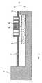
- a schematic cross-sectional view of such a chip, i.e. a fluid handling device according to the invention shown in Fig. 1 and designated by the reference numeral 20, 1further shows an enlarged view 22 of the area, in which the nozzle openings 14 are arranged.
- the chip or substrate 20has a first surface 21 and a second surface 23.
- the nozzles 14are in the second surface 23, i.e. in the figures in the bottom, of the chip 20 microstructured and compared to the surrounding silicon surface exposed.
- 1are six nozzles 14 arranged side by side, wherein a bottom view of the chip with the bottom of the same Structured nozzles 14 is shown in Fig. 2, wherein it can be seen that the illustrated embodiment of a Dosing head contains twenty four nozzles.
- the nozzles in the illustrated embodimentcompared to the surrounding silicon surface exposed, the dosing head in the bottom view of the same is surrounded by a border 24.
- the nozzles 14are in the illustrated embodiment via fluid lines or media lines 26 with media reservoirs 28 (FIG. 3) connected, which are also integrated on the chip.
- the Media reservoirs 28are in the first surface 21 of the Chips 20 structured. Due to the representation as a cross section are the four inner media lines in Fig. 1 only seen as vertical lines.
- FIG. 3A schematic plan view of the dosing head shown in Fig. 1 20 is shown in Fig. 3, with twenty four Media reservoirs 28, which are connected to respective media lines 26 Nozzles 14 are connected are shown.
- the media reservoirs 28are in the illustrated embodiment in the surface of the chip opposite the nozzles 14, that forms the dosing head, structured.
- the media reservoirs 28are preferably designed to be used with standard automatic pipetting machines automatically filled with liquids can be. They can do this, for example have identical diameters and distances as the chambers a known microtiter plate, for example a 348-well microtiter plate.
- the liquid from the media reservoirs 28is preferably by capillary forces over the Media lines 26 drawn to the nozzles 14.
- the media lines 26serve to be the closely spaced Nozzles 14 with liquid from a larger reservoir 28 supply.
- the structurecan be filled by an active Control, for example the application of an external pressure, get supported.
- the nozzles described with reference to FIGS. 1 to 3can have a diameter of 200 ⁇ m, for example, the media lines 26 also having a width of Can have 200 microns. So twenty four can be comfortably Nozzles in an array of six by four nozzles, like can be seen in Fig. 2, at a mutual distance of 1 mm Arrange.
- the limiting factor for the number of nozzles, that can be arranged in an arrayis the width of the Connection channels that connect the nozzles to the reservoirs. These connection channels must be between the nozzles be led outside. When the width is reduced these channels can also have 48, 96 or more nozzles accommodate a dosing head.
- FIG. 4is a schematic cross-sectional view of a Device for applying microdroplets to a substrate 2, in which the fluid handling device according to the invention is usable.
- a piezo bending transducer 4is on one side on a bracket 6 clamped, at the non-clamped end of the piezo bending transducer 4, a dosing head 8 is attached.
- the dosing head 8can by a fluid handling device according to the invention be educated.
- the holder 6is designed such that it forms a stop 10 through which a movement of the piezo bending transducer 4 and thus of the dosing head 8, shown schematically by arrow 12 is limited at the bottom in the representation of FIG. 4.
- the dosing head 8has a plurality of the nozzle openings 14 on, above which a quantity of liquid is arranged is as indicated schematically by reference numeral 16 is and will be explained in more detail below.
- the piezo bending transducer 4is now driven to to move the dosing head 8 downwards. This movement will abruptly ended when the right end of the piezo bending transducer hits the stop 10 so that the dosing head 8 with a strong negative acceleration is applied.
- This strong negative accelerationcauses inertia the amounts of liquid arranged above the nozzle openings 14 16 that a microdroplet from the nozzle openings 14 is driven and hits the substrate 2.
- These different liquidscan thereby by means of the plurality of nozzle openings 14 an array of analytes can be generated on the substrate 2.
- it is advantageous that the dosing head 8 at the time when the same with the negative acceleration is applied immediatelyis placed adjacent to the substrate to an exact To allow positioning of the microdroplets on the substrate 2 and further to cause possible satellite droplet fractions unite with the mother droplet.
- the actual profile of the acceleration with which the dosing head can be applied via the slope the voltage signal with which the bending transducer is drivenwill be varied.
- the amplitude of the movementcan be simple over the length of the piezo bending transducer or the amplitude of the voltage signal are adapted, as in Fig. 4 shows a stop 10 can be provided to to support the abrupt braking of the dosing head. alternative it may be sufficient to brake suddenly of the dosing head via an electrical control signal to cause high slope.
- a piezo stack actuatorIn addition to the piezo bending transducer shown in FIG. 4 as a drive device for the sudden acceleration of the Dosing head used, for example, a piezo stack actuator become. In this case, however, it is recommended the path length of the actuator, which is typically between 20 ⁇ m and 100 ⁇ m is to enlarge by a mechanical lever. All in all it is advantageous if the entire route to the the dosing head is moved is larger than the diameter the drop that is thrown out of the nozzle should. Otherwise there is a risk of very small movements that a drop that is already outside the nozzle is pulled back into the nozzle before it completes can tear off. Furthermore, it can be advantageous the dosing head after the sudden braking, after the same has moved towards the substrate, again with high Speed to move away from the substrate to thereby to influence the tear-off of the drop advantageously.
- the dosing qualitycan vary from the flow resistances depend on the liquid in the media lines. It can therefore be preferred for the dosing head directly mass of liquid above the nozzle to increase to achieve that the dosing quality regardless of the Flow resistance of the media lines is.
- embodiments of dosing headswhere such an enlargement the liquid mass realized above the nozzles 6 and 7 are shown.
- an axial riseris above the nozzles 14 34 arranged opposite to the direction of ejection extends.
- These riserscan have a T-shaped connection (not shown) close to the nozzle the media lines are tied up, which remains unchanged the top of the chip. Fill the risers 34 yourself with liquid from the media lines alone due to capillary forces.
- the media linesfor the sake of clarity in the cross-sectional views 5 to 7 are not shown.
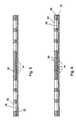
- FIGS. 7a) and 7b)are two sectional views of the dosing head 8, in the device shown in Fig. 1 is used, is shown, the section in Fig. 7a) shows four nozzles 14 along the transverse direction, while the section in Fig. 7b) along the longitudinal direction six nozzles 14 shows so that there is again a total of twenty four Results in nozzles.
- a further layer 36is arranged over the cover layer 30, the enlarged media reservoirs 38 and other enlarged risers 40 provides. This too Riser lines 40 fill with liquid from the media lines (not shown) solely due to capillary forces. So the external reservoirs are very easy to fill with standard pipetting machines while the risers are automatically filled via capillary forces.
- the risers 34 and 40which are open at the top, cause that the liquid mass standing directly above the nozzle increases is.
- the liquid in the risersbecomes different from the liquid in the media lines 26 or the liquid in the reservoirs 28 directly in Accelerated towards the nozzle and is over a minimal Flow resistance coupled to this.
- the liquidmust be overcome much greater flow resistance.
- the risersare 34 or 40 executed such that they are due to capillary forces are always filled with liquid.
- each nozzle onehas its own liquid storage area, can also several nozzles form a nozzle group and over a common one Media line are supplied with the same liquid. It is also possible to have several cover plates one above the other to increase the packing density of the nozzles, since then the system of media lines on several Levels can be distributed. By placing lines on different Levels are managed, these can also seemingly cross without mixing the different liquids takes place in the respective lines.
- FIG. 8is a further embodiment of an inventive Fluid handling device shown at which, in comparison to FIG. 7b), the risers 40 are omitted are.
- the fluid handling device of the inventionit can also be used as a dosing head be used advantageously to format conversion between microtiter plates with different grid dimensions to realize.
- the pattern of entrance openings and exit openings to different grid dimensionsbe adapted from microtiter plates, so that by means of a fluid of the inlet openings a microtiter plate with a first grid dimension can and the fluid through the outlet openings or the liquid to a microtiter plate with a second grid dimension can be output.
Landscapes
- Chemical & Material Sciences (AREA)
- Organic Chemistry (AREA)
- Health & Medical Sciences (AREA)
- Engineering & Computer Science (AREA)
- Chemical Kinetics & Catalysis (AREA)
- Mechanical Engineering (AREA)
- General Health & Medical Sciences (AREA)
- General Physics & Mathematics (AREA)
- Immunology (AREA)
- Pathology (AREA)
- Biochemistry (AREA)
- Analytical Chemistry (AREA)
- Clinical Laboratory Science (AREA)
- Life Sciences & Earth Sciences (AREA)
- Physics & Mathematics (AREA)
- General Engineering & Computer Science (AREA)
- Automatic Analysis And Handling Materials Therefor (AREA)
- Feeding, Discharge, Calcimining, Fusing, And Gas-Generation Devices (AREA)
- External Artificial Organs (AREA)
- Sampling And Sample Adjustment (AREA)
- Application Of Or Painting With Fluid Materials (AREA)
- Infusion, Injection, And Reservoir Apparatuses (AREA)
- Physical Or Chemical Processes And Apparatus (AREA)
- Investigating Or Analysing Biological Materials (AREA)
- Apparatus Associated With Microorganisms And Enzymes (AREA)
- Branch Pipes, Bends, And The Like (AREA)
- Coating Apparatus (AREA)
- Non-Metallic Protective Coatings For Printed Circuits (AREA)
Abstract
Description
Translated fromGermanDie vorliegende Erfindung bezieht sich auf eine Fluidhandhabungsvorrichtung,die eine Formatumwandlung zwischen einerMehrzahl von Fluideingängen und einer Mehrzahl von Fluidausgängenliefert, die beispielsweise zur Verwendung in einemDosierkopf geeignet ist.The present invention relates to a fluid handling device,which is a format conversion between oneA plurality of fluid inlets and a plurality of fluid outletsprovides, for example, for use in aDosing head is suitable.
Die erfindungsgemäße Fluidhandhabungsvorrichtung ist beispielsweisevorteilhaft in dem Dosierkopf einer Vorrichtungzum Aufbringen zumindest eines Mikrotröpfchens auf ein Substratverwendbar, mit der eine Mehrzahl von Mikrotröpfchenauf ein Substrat aufbringbar sind. Insbesondere ist die erfindungsgemäßeFluidhandhabungsvorrichtung geeignet, um beider Erzeugung von sogenannten Biochips, bei denen eine Mehrzahlunterschiedlicher Analyte auf ein Substrat aufgebrachtist, um unterschiedliche Stoffe in einer unbekannten Probenachzuweisen, verwendet zu werden. Daneben ist die vorliegendeErfindung geeignet, um eine Formatumwandlung zwischenMikrotiterplatten mit unterschiedlichen Rastermaßen zu implementieren.The fluid handling device according to the invention is, for exampleadvantageous in the dosing head of a devicefor applying at least one microdroplet to a substrateusable with a plurality of microdropletscan be applied to a substrate. In particular, the inventionFluid handling device suitable tothe production of so-called biochips, in which a majoritydifferent analytes applied to a substrateis about different substances in an unknown sampledemonstrate to be used. Next to it is the present oneInvention suitable for a format conversion betweenTo implement microtiter plates with different grid dimensions.
Die zunmehmende Entschlüsselung der Genome von Menschen,Tieren und Pflanzen schafft eine Vielzahl neuer Möglichkeiten,von der Diagnose von genetisch bedingten Krankheitenbis hin zur wesentlich beschleunigten Suche nach pharmazeutischinteressanten Wirkstoffen. So werden beispielsweisedie oben genannten Biochips künftig eingesetzt werden, umLebensmittel hinsichtlich einer Vielzahl möglicher, gentechnischveränderter Bestandteile zu untersuchen. In einem weiterenAnwendungsgebiet können derartige Biochips verwendetwerden, um bei genetisch bedingten Krankheiten den genauenGendefekt festzustellen, um daraus die ideale Strategie zurBehandlung der Krankheit abzuleiten.The increasing decoding of human genomes,Animals and plants create a multitude of new opportunitiesfrom the diagnosis of genetic diseasesto the much accelerated search for pharmaceuticalsinteresting active ingredients. For examplethe above biochips will be used in the futureFood in terms of a variety of possible, genetically engineeredto investigate changed components. In anotherSuch biochips can be used in the field of applicationto be the exact one in genetically caused diseasesIdentify genetic defects in order to find the ideal strategy forDerive treatment of the disease.
Die Biochips, die für derartige Anwendungen verwendbar sind,bestehen in der Regel aus einem Trägermaterial, d.h. einemSubstrat, auf welches eine Vielzahl unterschiedlicher Substanzenin Form eines Rasters, aufgebracht wird. TypischeRasterabstände in dem Array liegen zwischen 100 µm und 1.000µm. Die Vielfalt der unterschiedlichen Substanzen, die alssogenannte Analyte bezeichnet werden, auf einem Biochipreicht je nach Anwendung von einigen wenigen unterschiedlichenStoffen bis hin zu einigen 100.000 verschiedenen Stoffenpro Substrat. Mit jedem dieser unterschiedlichen Analytekann ein ganz bestimmter Stoff in einer unbekannten Probenachgewiesen werden.The biochips that can be used for such applicationsusually consist of a carrier material, i.e. oneSubstrate on which a variety of different substancesin the form of a grid. typicalThe grid spacing in the array is between 100 µm and 1,000microns. The variety of different substances that asso-called analytes are referred to on a biochipranges from a few different ones depending on the applicationFabrics up to some 100,000 different fabricsper substrate. With each of these different analytescan be a specific substance in an unknown samplebe detected.
Bringt man eine unbekannte Probenflüssigkeit auf einen Biochipauf, so treten bei bestimmten Analyten Reaktionen auf,die über geeignete Verfahren, beispielsweise eine Fluoreszenzerfassungdetektiert werden können. Die Anzahl der unterschiedlichenAnalyte auf dem Biochip entspricht dabei derAnzahl der unterschiedlichen Bestandteile in der unbekanntenProbenflüssigkeit, die mit dem jeweiligen Biochip gleichzeitiganalysiert werden können. Bei einem solchen Biochip handeltes sich somit um ein Diagnosewerkzeug, mit welchem eineunbekannte Probe gleichzeitig und gezielt hinsichtlich einerVielzahl von Inhaltsstoffen untersucht werden kann.You bring an unknown sample liquid onto a biochipreactions occur with certain analytes,via suitable methods, for example fluorescence detectioncan be detected. The number of differentAnalyte on the biochip corresponds to thatNumber of different components in the unknownSample liquid that is simultaneously with the respective biochipcan be analyzed. Acting in such a biochipit is therefore a diagnostic tool with which aunknown sample simultaneously and targeted for oneVariety of ingredients can be examined.
Zum Aufbringen der Analyte auf ein Substrat, um einen solchenBiochip zu erzeugen, sind derzeit drei grundsätzlichverschiedene Verfahren bekannt. Diese Verfahren werden alternativje nach benötigter Stückzahl der Biochips bzw. nachnotwendiger Analytenzahl pro Chip eingesetzt.To apply the analytes to a substrateTo produce biochip are currently threeknown various processes. These procedures become alternativedepending on the required number of biochips or afternecessary number of analytes per chip used.
Das erste Verfahren wird als "Contactprinting" bezeichnet,wobei bei diesem Verfahren ein Bündel aus Stahlkapillarenverwendet wird, die im Inneren mit verschiedenen Analytengefüllt sind. Dieses Bündel aus Stahlkapillaren wird auf dasSubstrat gestempelt. Beim Abheben des Bündels bleiben die Analyte in Form von Mikrotröpfchen an dem Substrat haften.Bei diesem Verfahren wird die Qualität des Druckmusters allerdingssehr stark durch die Wirkung von Kapillarkräftenbestimmt und hängt dadurch von einer Vielzahl von kritischenParametern ab, beispielsweise der Qualität und der Beschichtungder Oberfläche des Substrats, der genauen Geometrie derDüse und vor allem von den verwendeten Medien. Daneben istdas Verfahren sehr anfällig gegenüber Verunreinigungen desSubstrats sowie der Düsen. Dieses eben beschriebene Verfahreneignet sich bis zu einer Analytenvielfalt von einigen100 pro Substrat.The first method is called "contact printing",with this method a bundle of steel capillariesis used inside with different analytesare filled. This bundle of steel capillaries is on theStamped substrate. When lifting the bundle they remainAnalytes adhere to the substrate in the form of microdroplets.With this method, however, the quality of the print patternvery strong due to the action of capillary forcesdetermined and therefore depends on a variety of criticalParameters, such as quality and coatingthe surface of the substrate, the exact geometry of theNozzle and especially of the media used. Is next to itthe process is very susceptible to contamination of theSubstrate and the nozzles. This procedure just describedis suitable for a variety of analytes of a few100 per substrate.
Bei einem zweiten Verfahren zum Erzeugen von Biochips, demsogenannten "Spotting" werden meist sogenannte Mikrodispensereingesetzt, die ähnlich wie Tintendrucker in der Lagesind, einzelne Mikrotröpfchen einer Flüssigkeit auf einenentsprechenden Steuerbefehl hin auf ein Substrat zuschießen. Ein solches Verfahren wird als "drop-on-demand"bezeichnet. Solche Mikrodispenser sind von einigen Firmenkommerziell erhältlich. Der Vorteil bei diesem Verfahrenliegt darin, daß die Analyte berührungslos auf ein Substrataufgebracht werden können, wobei der Einfluß von Kapillarkräftenbedeutungslos ist. Ein wesentliches Problem bestehtjedoch darin, daß es sehr teuer und überaus schwierig ist,eine Vielzahl von Düsen, die alle mit unterschiedlichen Medienversorgt werden, parallel, bzw. in einem Array, anzuordnen.Das limitierende Element ist hierbei die Aktoriksowie die Medienlogistik, die nicht in dem gewünschten Maßeminiaturisierbar sind.In a second method for producing biochips, theSo-called "spotting" are usually so-called microdispensersused that is capable of similar to ink printersare single microdroplets of a liquid on onecorresponding control command towards a substrateshoot. Such a process is called "drop-on-demand"designated. Such microdispensers are from some companiescommercially available. The advantage with this procedureis that the analytes are non-contact on a substratecan be applied, the influence of capillary forcesis meaningless. There is a major problemhowever in that it is very expensive and extremely difficulta variety of nozzles, all with different mediabe arranged in parallel or in an array.The limiting element here is the actuatorsas well as media logistics, which are not to the desired extentare miniaturizable.
Als ein drittes Verfahren zur Herstellung von Biochips wirdderzeit das sogenannte "Syntheseverfahren" verwendet, beidem die Analyte, die in der Regel aus einer Kette aneinanderhängenderNukleinsäuren bestehen, chemisch auf dem Substrathergestellt, also synthetisiert werden. Zur Abgrenzungder räumlichen Position der unterschiedlichen Analyte werdenVerfahren verwendet, wie sie aus der Mikroelektronik bekannt sind, beispielsweise Lithographieverfahren mit Maskentechnik.Dieses Syntheseverfahren ist unter dem genannten Verfahrenmit Abstand das teuerste, wobei jedoch die größteAnalytenvielfalt auf einem Chip herstellbar ist, in derGrößenordnung von 100.000 verschiedenen Analyten pro Substrat.As a third method of making biochipscurrently uses the so-called "synthetic process" atwhich are the analytes, which are usually linked together from a chainNucleic acids exist chemically on the substratemanufactured, that is, synthesized. For demarcationthe spatial position of the different analytesProcesses used as known from microelectronicsare, for example, lithography processes with mask technology.This synthetic method is under the mentioned methodby far the most expensive, but the largestA variety of analytes can be produced on a chip in whichThe order of 100,000 different analytes per substrate.
Aus der WO-A-93/09668 sind Verfahren zum Bilden von Polymerenmit unterschiedlichen Monomersequenzen auf einem einzelnenSubstrat bekannt, bei denen über eine Mehrzahl von Kanälen,die in einem Kanalblock gebildet sind, Monomere an ausgewählteRegionen gebracht werden, um an diesen Regionen Polymerezu synthetisieren. Zu diesem Zweck weisen die KanalblöckeKanäle auf, die in einer Oberfläche nach außen geöffnetsind und die einen Einlaß und einen Auslaß, die in dergegenüberliegenden Oberfläche des Kanalblocks gebildet sind,aufweisen. Über die Einlaßöffnung wird ein gewünschtes Reagenzzu dem Kanal geliefert, während an die Auslaßöffnungeine Vakuumpumpe angeschlossen wird.WO-A-93/09668 describes processes for forming polymerswith different monomer sequences on a single oneKnown substrate in which over a plurality of channels,formed in a channel block, monomers to selected onesRegions are brought to polymers on these regionsto synthesize. For this purpose, the channel blocksChannels on that open to the outside in a surfaceare and which have an inlet and an outlet, which in theopposite surface of the channel block are formed,exhibit. A desired reagent is supplied via the inlet openingdelivered to the duct while to the outlet openinga vacuum pump is connected.
Die WO-A-97/45730 bezieht sich auf Verfahren und Vorrichtungen,um Lösungen zu einem Array von Zellen zuzuführen. Zudiesem Zweck wird ein Array von Zellen auf einem Substratgebildet. Ein weiteres Substrat besitzt Ausnehmungen und mitden Ausnehmungen verbundene Mikrokanäle, die es ermöglichen,ein Fluid in die Ausnehmungen zu liefern. Die Zellen werdennun in die Ausnehmungen eingebracht, woraufhin Lösungendurch die Kanäle in die Ausnehmungen gebracht werden, um dieZellen zu behandeln. Die Mikrokanäle sind mit Mikrokapillarröhrenverbunden, über die beispielsweise unter Verwendungeiner Mikrotiterplatte Lösungen zugeführt werden können.WO-A-97/45730 relates to methods and devicesto deliver solutions to an array of cells. Toto this end, an array of cells on a substrateeducated. Another substrate has recesses and withthe microchannels connected to the recesses, which enableto deliver a fluid into the recesses. The cells willnow introduced into the recesses, whereupon solutionsthrough the channels in the recesses to theTo treat cells. The microchannels are with microcapillary tubesconnected, for example usingsolutions can be fed to a microtiter plate.
Der vorliegenden Erfindung liegt die Aufgabe zugrunde, eineFluidhandhabungsvorrichtung zu schaffen, die es ermöglicht,Mikrotröpfchen aus einer Mehrzahl von Fluidreservoiren ineinem vorbestimmten Muster kostengünstig und exakt auf einSubstrat aufzubringen.The present invention has for its object aTo provide fluid handling device that allowsMicrodroplets from a plurality of fluid reservoirs ina predetermined pattern inexpensively and precisely on aApply substrate.
Diese Aufgabe wird durch eine Fluidhandhabungsvorrichtungnach Anspruch 1 oder Anspruch 2 gelöst.This task is accomplished by a fluid handling devicesolved according to claim 1 or claim 2.
Die vorliegende Erfindung schafft somit eine Fluidhandhabungsvorrichtung,die eine Formatumwandlung zwischen einemersten Muster und einem zweiten Muster liefert. Die automatischeFormatumwandlung wird durch die Anordnung der Fluideingänge,der Fluidausgänge und durch die Medienleitungenbewirkt. Das Substrat der erfindungsgemäßen Fluidhandhabungsvorrichtungist vorzugsweise mikromechanisch, d.h. beispielsweisedurch Siliziumbearbeitungstechniken oder Spritzgußtechniken,gefertigt.The present invention thus provides a fluid handling devicewhich is a format conversion between onefirst pattern and a second pattern. The automaticFormat conversion is achieved through the arrangement of the fluid inputs,the fluid outlets and through the media linescauses. The substrate of the fluid handling device according to the inventionis preferably micromechanical, i.e. for examplethrough silicon processing techniques or injection molding techniques,manufactured.
Die in der ersten Oberfläche des Substrats der erfindungsgemäßenFluidhandhabungsvorrichtung gebildeten Fluideingängesind vorzugsweise als Fluidreservoire ausgebildet, die imRastermaß von gebräuchlichen Mikrotiterplatten, die beispielsweise96, 384, 1536, usw., Kammern aufweisen, angeordnetsind. Somit können die Fluidreservoire mit konventionellenLabor-Pipettierautomaten automatisiert und parallel befülltwerden. Dagegen sind die Düsen vorzugsweise in dem engerenRaster angeodnet, in dem Analyte auf Microarrays bzw.Biochips aufgebracht werden sollen.Those in the first surface of the substrate of the inventionFluid handling device formed fluid inputsare preferably designed as fluid reservoirs in theGrid size of common microtiter plates, for example96, 384, 1536, etc., have chambers arrangedare. Thus the fluid reservoirs can be used with conventionalLaboratory automated pipetting machines and filled in parallelbecome. In contrast, the nozzles are preferably in the narrowerArranged grid in which analytes on microarrays orBiochips are to be applied.
Die vorliegende Erfindung basiert auf der Erkenntnis, daßbei den oben genannten bekannten Verfahren jeweils ein Positioniervorgangnotwendig ist, um Flüssigkeiten, die aus weitvoneinander entfernten Reservoirs aufgenommen werden, in engenAbständen auf ein Substrat zu drucken. Erfindungsgemäßkann die Fluidhandhabungsvorrichtung mit Standard-Automatenbefüllt werden, wobei, obwohl die Flüssigkeit in "weit" voneinanderbeabstandete Öffnungen (Reservoire) eingefülltwird, Mikrotröpfchen ohne weiteren Positionierungsvorganggleichzeitig und eng benachbart zueinander gedruckt werdenkönnen.The present invention is based on the finding thata positioning process in each of the known methods mentioned aboveis necessary to keep liquids from fardistant reservoirs can be accommodated in narrowTo print gaps on a substrate. According to the inventionthe fluid handling device can be operated with standard machinesbe filled, although the liquid is in "far" from each otherspaced openings (reservoirs) filledbecomes microdroplets without further positioningprinted simultaneously and closely adjacent to each othercan.
Die erfindungsgemäße Fluidhandhabungsvorrichtung kann alsein Dosierkopf dienen oder in einem solchen vorteilhaft verwendetwerden. Der Dosierkopf besitzt vorzugsweise Flüssigkeitsspeicherbereiche,die mit den Düsenöffnungen der Fluidhandhabungsvorrichtungfluidmäßig verbunden sind, derart,daß durch ein Beaufschlagen des Dosierkopfes mit einer Beschleunigungdurch die Trägheit einer in dem Flüssigkeitsspeicherbereichenvorliegenden Flüssigkeit Mikrotröpfchenaus der Düsenöffnung treibbar sind. Dabei kann der Flüssigkeitsspeicherbereichvorzugsweise durch eine Steigleitunggebildet sein, die sich in einer Richtung von der Düsenöffnungweg erstreckt, die entgegengesetzt zu der Richtung ist,in der das Mikrotröpfchen aus dem Dosierkopf treibbar ist.The fluid handling device according to the invention can be used asserve a dosing head or used advantageously in suchbecome. The dosing head preferably has liquid storage areas,with the nozzle openings of the fluid handling deviceare fluidly connected, suchthat by applying an acceleration to the dosing headby the inertia of one in the liquid storage areaspresent liquid microdropletscan be driven out of the nozzle opening. The liquid storage areapreferably by a riserbe formed in a direction from the nozzle openingextends away which is opposite to the directionin which the microdroplet can be driven out of the dosing head.
Die vorliegende Erfindung schafft somit eine Fluidhandhabungsvorrichtung,mit der beispielsweise Biochips kostengünstigin hohen Stückzahlen hergestellt werden können. Fernerist die erfindungsgemäße Fluidhandhabungsvorrichtung geeignet,um eine Formatumwandlung zwischen Mikrotiterplatten mitunterschiedlichen Rastermaßen durchzuführen.The present invention thus provides a fluid handling devicewith the for example biochips inexpensivecan be produced in large numbers. Furtherthe fluid handling device according to the invention is suitable,format conversion between microtiter platesdifferent grid dimensions.
Insbesondere ermöglicht die Erfindung vorteilhaft die Implementierungeines Dosierkopfes, bei dem durch eine mechanischeBeschleunigung, mit der ein Dosierkopf durch ein externesmechanisches System beaufschlagt wird, Mikrotröpfchenaus dem Dosierkopf getrieben werden. Bei dem externen mechanischenSystem, daß eine Antriebseinrichtung darstellt, könnenbeliebige geeignete Vorrichtungen verwendet werden, beispielsweisePiezo-Biegewandler, Piezo-Stapel, pneumatischeAntriebe und dergleichen. Auf eine Flüssigkeit, die sich inmit der Düsenöffnung fluidmäßig verbundenen Bereichen, d.h.beispielsweise der Düse selbst, einer Medienleitung und einemReservoir befinden wirken dabei Trägheitskräfte. Da dieFlüssigkeit nicht starr mit dem Dosierkopf verbunden ist,ergibt sich infolge der Trägheitskräfte eine Beschleunigungder Flüssigkeit relativ zu dem die Flüssigkeit tragenden Dosierkopf.Die Flüssigkeit setzt sich somit relativ zu demDosierkopf in Bewegung. Ist diese Relativbewegung zwischender sich in der Düse befindlichen Flüssigkeit und der Düsenöffnunggroß genug, so reißt ein Mikrotropfen an der Düseab. Die Größe dieses Tropfens ist durch die Größe und Dauerder Beschleunigung des Dosierkopfes, die Größe der Flüssigkeitsmasse,durch deren Trägheit der Ausstoß bewirkt wird,den Düsendurchmesser sowie den Strömungswiderstand der Bewegungder Flüssigkeit in dem Dosierkopf bestimmt. Die Richtungder Beschleunigung, mit der der Dosierkopf beaufschlagtwird, muß dabei so orientiert sein, daß die Flüssigkeit aufgrundihrer Trägheit aus der Düse herausgeschleudert wirdund sich nicht in Flüssigkeitsspeicherbereiche oder Medienleitungenin dem Dosierkopf zurückzieht.In particular, the invention advantageously enables implementationa dosing head, in which a mechanicalAcceleration with which a dosing head by an externalmechanical system is applied, microdropletsbe driven out of the dosing head. With the external mechanicalSystem that represents a drive device canany suitable devices can be used, for examplePiezo bending transducer, piezo stack, pneumaticDrives and the like. On a liquid that is inareas fluidly connected to the nozzle opening, i.e.for example the nozzle itself, a media line and oneInertial forces act in the reservoir. Since theLiquid is not rigidly connected to the dosing head,there is an acceleration due to the inertial forcesthe liquid relative to the dosing head carrying the liquid.The liquid thus settles relative to thatDosing head in motion. Is this relative movement betweenthe liquid in the nozzle and the nozzle openinglarge enough, a microdroplet tears at the nozzlefrom. The size of this drop is due to the size and durationthe acceleration of the dosing head, the size of the liquid mass,whose inertia causes the ejection,the nozzle diameter and the flow resistance of the movementof the liquid in the dosing head. The directionthe acceleration with which the dosing head actsmust be oriented so that the liquid due totheir inertia is thrown out of the nozzleand not in liquid storage areas or media linesin the dosing head.
Unter Verwendung der erfindungsgemäßen Fluidhandhabungsvorrichtungwird gleichzeitig eine Mehrzahl von Mikrotröpfchenauf ein Substrat aufgebracht, so daß kostengünstig und zuverlässigbeispielsweise ein Biochip, bei dem unterschiedlichebiologisch relevante Stoffe in einem regelmäßigen Musterauf ein Substrat aufgebracht sind, erzeugt werden kann.Durch die Beschleunigung des Dosierkopfes wird aus jedereinzelnen Düse in einem Dosierkopf gleichzeitig ein Mikrotröpfchenherausgetrieben, wobei die Trägheit der Flüssigkeitgenutzt wird.Using the fluid handling device according to the inventionbecomes a plurality of microdroplets at the same timeapplied to a substrate so that inexpensive and reliablefor example a biochip where differentbiologically relevant substances in a regular patternare applied to a substrate, can be generated.By accelerating the dosing head, everyone becomessingle nozzle in a dosing head simultaneously a microdropletexpelled, the inertia of the liquidis being used.
Der Dosierkopf mit der erfindungsgemäßen Fluidhandhabungsvorrichtungkann dabei mit unterschiedlichen Beschleunigungenbeaufschlagt werden, um den Ausstoß von Flüssigkeitströpfchenzu bewirken. Eine Möglichkeit besteht darin, denDosierkopf aus einer Position benachbart zu dem Substratsehr stark aus seiner Ruhelage heraus zu beschleunigen, umeine Bewegung des Dosierkopfes von dem Substrat weg zu bewirken.Eine alternative Möglichkeit besteht darin, den Dosierkopfaus einer kontinuierlichen Bewegung zu dem Substrathin heraus abrupt abzubremsen, wobei dieses Abbremsen beispielsweisedurch einen mechanischen Anschlag unterstütztwerden kann. Daneben ist es ebenfalls möglich, eine mechanischgenügend steife Halterung für den Dosierkopf vorzusehen,die in Bereiche der Eigenfrequenz derselben angeregtwird, derart, daß die Halterung und damit der Dosierkopfeine Halbschwingung durchführt. Die maximale Beschleunigungtritt in diesem Fall im Umkehrpunkt der Schwingung auf, sodaß die Halterung und der Dosierkopf derart angeordnet werden,daß der Dosierkopf im Umkehrpunkt der Schwingung benachbartzu dem Substrat angeordnet ist.The dosing head with the fluid handling device according to the inventioncan with different accelerationsto be applied to the discharge of liquid dropletsto effect. One way is toDosing head from a position adjacent to the substrateto accelerate very strongly from its rest position tocause movement of the dosing head away from the substrate.An alternative option is the dosing headfrom a continuous movement to the substrateto brake out abruptly, this braking for examplesupported by a mechanical stopcan be. In addition, it is also possible to use a mechanicalprovide enough rigid support for the dosing head,which are excited in areas of their natural frequencyis such that the holder and thus the dosing headperforms a half oscillation. The maximum accelerationin this case occurs at the point of reversal of the vibration, sothat the holder and the dosing head are arranged in such a waythat the dosing head is adjacent to the point of oscillationis arranged to the substrate.
Wird ein solcher Dosierkopf aus einer Bewegung auf das Substratzu unmittelbar vor dem Substrat schlagartig abgebremst,behält die Flüssigkeit aufgrund ihrer Trägheit undaufgrund der Tatsache, daß sie mit dem Dosierkopf nichtstarr verbunden ist, ihre Bewegung bei und wird aus der Düse heraus auf das Substrat geschleudert. Wird ein unmittelbarüber einem Substrat befindlicher, ruhender Dosierkopfschlagartig vom Substrat weg beschleunigt, kann die Flüssigkeitaufgrund ihrer Trägkeit und aufgrund der Tatsache, daßsie mit dem Dosierkopf nicht starr verbunden ist, dieser Bewegungnicht folgen, und verläßt die Düse entgegengesetztzur Richtung der Bewegung des Dosierkopfes, die durch dieBeschleunigung von dem Substrat weg bewirkt wird, und stehtzunächst frei im Raum, bevor die Tropfen aufgrund derSchwerkraft auf das Substrat fallen. Hierbei kann eine Vorrichtungvorgesehen sein, um ein elektrostatisches Feld zwischenDosierkopf und Substrat zu erzeugen, um dadurch dasAufbringen der Tröpfchen auf das Substrat zu unterstützen.Such a dosing head is made by moving onto the substratebraked too suddenly in front of the substrate,retains the liquid due to its inertia anddue to the fact that they are not with the dosing headis rigidly connected to their movement and gets out of the nozzlehurled out onto the substrate. Becomes an immediatedosing head resting above a substrateThe liquid can suddenly accelerate away from the substratebecause of their inertia and because of the fact thatit is not rigidly connected to the dosing head, this movementdoes not follow, and leaves the nozzle oppositeto the direction of movement of the dosing head caused by theAcceleration is caused away from the substrate, and standsfirst free in the room before the drops due to theGravity falling on the substrate. Here, a devicebe provided to create an electrostatic field betweenDosing head and substrate to create theSupport application of the droplets to the substrate.
In beiden oben genannten Fällen ist es günstig, wenn die Beschleunigungdes Dosierkopfes in einer Position geschieht,in der der Abstand zwischen den Düsen in dem Dosierkopf unddem Substrat sehr gering ist. Dann ist gewährleistet, daß,wenn sich beim Ablösen der Mikrotropfen jeweils Satellitentropfenbilden, diese sich spätestens auf dem Substrat mitdem Muttertropfen vereinigen. Durch den geringen Abstand istsichergestellt, daß die Satellitentropfen auch dann auf demMuttertropfen landen, wenn sie die Düse unter einem etwasanderen Winkel verlassen haben.In both of the above cases it is beneficial if the accelerationthe dosing head happens in one positionin which the distance between the nozzles in the dosing head andthe substrate is very small. Then it is guaranteed that,if there are satellite drops when the microdroplets are detachedform, at the latest on the substrateunite the mother drop. Because of the small distanceensured that the satellite drops even on theMother drops land when they put the nozzle under somethinghave left another angle.
Bevorzugte Ausführungsbeispiele der vorliegenden Erfindungwerden nachfolgend bezugnehmend auf die beiliegenden Zeichnungennäher erläutert. Es zeigen:
- Fig. 1
- schematisch eine Querschnittansicht eines Ausführungsbeispielseiner erfindungsgemäßen Fluidhandhabungsvorrichtungin der Form eines Dosierkopfes;
- Fig. 2
- schematisch eine Unteransicht des in Fig. 1 gezeigtenDosierkopfes;
- Fig. 3
- schematisch eine Draufsicht des in Fig. 1 gezeigten Dosierkopfes;
- Fig. 4
- schematisch ein Beispiel einer Verwendung der erfindungsgemäßenFluidhandhabungsvorrichtung bei einerVorrichtung zum Aufbringen von Mikrotröpfchen aufein Substrat; und
- Fig. 5, 6, 7a), 7b) und 8
- schematisch Querschnittansichtenvon Beispielen alternativer Fluidhandhabungsvorrichtungengemäß der Erfindung.
- Fig. 1
- schematically shows a cross-sectional view of an embodiment of a fluid handling device according to the invention in the form of a dosing head;
- Fig. 2
- schematically a bottom view of the dosing head shown in Fig. 1;
- Fig. 3
- schematically shows a plan view of the dosing head shown in Fig. 1;
- Fig. 4
- schematically shows an example of a use of the fluid handling device according to the invention in a device for applying microdroplets to a substrate; and
- 5, 6, 7a), 7b) and 8
- schematically cross-sectional views of examples of alternative fluid handling devices according to the invention.
Bezugnehmend auf die Figuren werden nachfolgend bevorzugteAusführungsbeispiele der vorliegenden Erfindung hinsichtlicheines Dosierkopfs detaillierter beschrieben. Es ist jedochklar, daß die erläuterten Grundsätze in gleicher Weise fürandere Fluidhandhabungsvorrichtungen, beispielsweise Einrichtungenzur Formatumwandlung zwischen Mikrotiterplattenmit unterschiedlichen Rastermaßen gelten können.Referring to the figures, preferred are belowEmbodiments of the present invention with respectof a dosing head described in more detail. However, it isit is clear that the principles explained in the same way forother fluid handling devices, e.g. facilitiesfor format conversion between microtiter platescan apply with different grid dimensions.
Bezugnehmend auf die Fig. 1 bis 3 wird nachfolgend ein bevorzugtesAusführungsbeispiel der erfindungsgemäßen Fluidhandhabungsvorrichtung,bei der es sich um einen Dosierkopfhandeln kann, näher erläutert. Bei dem Dosierkopf kann essich beispielsweise um einen Chip handeln, der mit den verfahrender Silizium-Mikromechanik hergestellt ist. Alternativekann der Dosierkopf beispielsweise mittels einerSpritzgußtechnik aus einem Kunststoff oder einem Polymer gebildetsein. Ferner kann der Dosierkopf aus einem Siliziumglasverbund,einem Metall oder einer Keramik bestehen.Referring to Figs. 1 to 3, a preferred one is as followsEmbodiment of the fluid handling device according to the invention,which is a dosing headcan act, explained in more detail. With the dosing head it canit is, for example, a chip that uses the methodsilicon micromechanics is manufactured. alternativecan the dosing head, for example, by means of aInjection molding technology made of a plastic or a polymerhis. Furthermore, the dosing head made of a silicon glass composite,a metal or ceramic.
Eine schematische Querschnittansicht eines solchen Chips,d.h. einer erfindungsgemäßen Fluidhandhabungsvorrichtung istin Fig. 1 gezeigt und mit dem Bezugszeichen 20 bezeichnet,wobei Fig. 1 ferner eine vergrößerte Ansicht 22 des Bereichs,in dem die Düsenöffnungen 14 angeordnet sind, enthält.Der Chip bzw. das Substrat 20 besitzt eine erste Oberfläche21 und eine zweite Oberfläche 23. Die Düsen 14 sind in der zweiten Oberfläche 23, d.h. in den Figuren in der Unterseite,des Chips 20 mikrostrukturiert und gegenüber derumgebenden Siliziumoberfläche exponiert. In Fig. 1 sindsechs nebeneinander angeordnete Düsen 14 dargestellt, wobeieine Unteransicht des Chips mit dem in der Unterseite desselbenstrukturierten Düsen 14 in Fig. 2 gezeigt ist, wobeizu sehen ist, daß das dargestellte Ausführungsbeispiel einesDosierkopfes vierundzwanzig Düsen enthält. Wie ebenfalls zuerkennen ist, sind die Düsen bei dem dargestellten Ausführungsbeispielgegenüber der umgebenden Siliziumoberflächeexponiert, wobei der Dosierkopf in der Unteransicht desselbenvon einer Umrandung 24 umgeben ist. Die Düsen 14 sindbei dem dargestellten Ausführungsbeispiel über Fluidleitungenbzw. Medienleitungen 26 mit Medienreservoirs 28 (Fig. 3)verbunden, die ebenfalls auf dem Chip integriert sind. DieMedienreservoirs 28 sind in der ersten Oberfläche 21 desChips 20 strukturiert. Aufgrund der Darstellung als Querschnittsind in Fig. 1 die vier inneren Medienleitungen lediglichals vertikale Leitungen zu sehen.A schematic cross-sectional view of such a chip,i.e. a fluid handling device according to the inventionshown in Fig. 1 and designated by the
Eine schematische Draufsicht des in Fig. 1 gezeigten Dosierkopfes20 ist in Fig. 3 dargestellt, wobei vierundzwanzigMedienreservoirs 28, die über Medienleitungen 26 mit jeweiligenDüsen 14 verbunden sind, dargestellt sind. Die Medienreservoirs28 sind bei dem dargestellten Ausführungsbeispielin der den Düsen 14 gegenüberliegenden Oberfläche des Chips,der den Dosierkopf bildet, strukturiert. Die Medienreservoirs28 werden vorzugsweise so ausgelegt, daß sie mit Standard-Pipettierautomatenautomatisiert mit Flüssigkeiten gefülltwerden können. Dazu können dieselben beispielsweiseidentische Durchmesser und Abstände besitzen wie die Kammerneiner bekannten Mikrotiterplatte, beispielsweise einer 348-Well-Mikrotiterplatte.Die Flüssigkeit aus den Medienreservoiren28 wird vorzugsweise durch Kapillarkräfte über dieMedienleitungen 26 zu den Düsen 14 gezogen. Die Medienleitungen26 dienen dabei dazu, die eng beieinanderliegendenDüsen 14 mit Flüssigkeit aus einem größeren Reservoir 28 zu versorgen. Die Befüllung der Struktur kann durch eine aktiveSteuerung, beispielsweise das Anlegen eines externen Drucks,unterstützt werden.A schematic plan view of the dosing head shown in Fig. 120 is shown in Fig. 3, with twenty four
Die bezugnehmend auf die Fig. 1 bis 3 beschriebenen Düsenkönnen beispielsweise einen Durchmesser von 200 µm aufweisen,wobei die Medienleitungen 26 ebenfalls eine Breite von200 µm aufweisen können. Somit lassen sich bequem vierundzwanzigDüsen in einem Array aus sechs mal vier Düsen, wiein Fig. 2 zu sehen ist, im gegenseitigen Abstand von 1 mmanordnen. Der limitierende Faktor für die Anzahl der Düsen,die sich in einem Array anordnen lassen, ist die Breite derVerbindungskanäle, welche die Düsen mit den Reservoirs verbinden.Diese Verbindungskanäle müssen zwischen den Düsennach außen geführt werden. Bei einer Reduzierung der Breitedieser Kanäle lassen sich auch 48, 96 oder mehr Düsen aufeinem Dosierkopf unterbringen.The nozzles described with reference to FIGS. 1 to 3can have a diameter of 200 µm, for example,the
In Fig. 4 ist eine schematische Querschnittansicht einerVorrichtung zum Aufbringen von Mikrotröpfchen auf ein Substrat2 dargestellt, bei der die erfindungsgemäße Fluidhandhabungsvorrichtungverwendbar ist. Wie in Fig. 4 gezeigtist, ist ein Piezo-Biegewandler 4 einseitig an einer Halterung6 eingespannt, wobei an dem nicht eingespannten Endedes Piezo-Biegewandlers 4 ein Dosierkopf 8 angebracht ist.Der Dosierkopf 8 kann durch eine erfindungsgemäße Fluidhandhabungsvorrichtunggebildet sein.4 is a schematic cross-sectional view of aDevice for applying microdroplets to a
Wie in Fig. 4 zu sehen ist, ist die Halterung 6 derart ausgestaltet,daß dieselbe einen Anschlag 10 bildet, durch deneine Bewegung des Piezo-Biegewandlers 4 und somit des Dosierkopfes8, die schematisch durch den Pfeil 12 gezeigtist, bei der Darstellung von Fig. 4 nach unten begrenzt ist.Der Dosierkopf 8 weist eine Mehrzahl der Düsenöffnungen 14auf, über denen jeweils eine Flüssigkeitsmenge angeordnetist, wie durch das Bezugszeichen 16 schematisch angezeigtist und im weiteren detaillierter erläutert wird.As can be seen in FIG. 4, the
Im Betrieb wird nun der Piezo-Biegewandler 4 angetrieben, umden Dosierkopf 8 nach unten zu bewegen. Diese Bewegung wirdabrupt beendet, wenn das rechte Ende des Piezo-Biegewandlersauf den Anschlag 10 trifft, so daß der Dosierkopf 8 mit einerstarken negativen Beschleunigung beaufschlagt wird.Durch diese starke negative Beschleunigung bewirkt die Trägheitder oberhalb der Düsenöffnungen 14 angeordneten Flüssigkeitsmengen16, daß ein Mikrotröpfchen aus den Düsenöffnungen14 getrieben wird und auf das Substrat 2 trifft. Handeltes sich dabei jeweils um unterschiedliche Flüssigkeiten,kann dadurch mittels der Mehrzahl von Düsenöffnungen 14ein Array von Analyten auf dem Substrat 2 erzeugt werden.Wie in Fig. 4 schematisch gezeigt ist, ist es vorteilhaft,daß der Dosierkopf 8 zu dem Zeitpunkt, zu dem derselbe mitder negativen Beschleunigung beaufschlagt wird, unmittelbarbenachbart zu dem Substrat angeordnet ist, um ein exaktesPositionieren der Mikrotröpfchen auf dem Substrat 2 zu ermöglichenund ferner zu bewirken, daß mögliche Satellitentröpfchenanteilesich mit dem Muttertröpfchen vereinigen.In operation, the
Das tatsächliche Profil der Beschleunigung, mit der der Dosierkopfbeaufschlagt wird, kann über die Flankensteilheitdes Spannungssignals, mit dem der Biegewandler angetriebenwird, variiert werden. Die Amplitude der Bewegung kann einfachüber die Länge des Piezo-Biegewandlers oder die Amplitudedes Spannungssignals angepaßt werden, wobei, wie inFig. 4 gezeigt ist, ein Anschlag 10 vorgesehen sein kann, umdas abrupte Abbremsen des Dosierkopfes zu unterstützen. Alternativkann es ausreichend sein, ein schlagartiges Abbremsendes Dosierkopfes über ein elektrisches Steuersignal mithoher Flankensteilheit zu bewirken.The actual profile of the acceleration with which the dosing headcan be applied via the slopethe voltage signal with which the bending transducer is drivenwill be varied. The amplitude of the movement can be simpleover the length of the piezo bending transducer or the amplitudeof the voltage signal are adapted, as inFig. 4 shows a
Neben dem in Fig. 4 dargestellten Piezo-Biegewandler kannals Antriebseinrichtung zur schlagartigen Beschleunigung desDosierkopfes beispielsweise ein Piezo-Stapelaktor verwendetwerden. In diesem Fall empfiehlt es sich jedoch, die Weglänge des Aktors, die typischerweise zwischen 20 µm und 100 µmliegt, durch einen mechanischen Hebel zu vergrößern. Insgesamtist es vorteilhaft, wenn die gesamte Strecke, um dieder Dosierkopf bewegt wird, größer ist als der Durchmesserdes Tropfens, der aus der Düse herausgeschleudert werdensoll. Bei sehr kleinen Bewegungen besteht sonst die Gefahr,daß ein Tropfen, der sich bereits außerhalb der Düse befindet,wieder in die Düse zurückgezogen wird, bevor er vollständigabreißen kann. Überdies kann es vorteilhaft sein,den Dosierkopf nach dem schlagartigen Abbremsen, nachdemsich derselbe auf das Substrat zubewegt hat, wieder mit hoherGeschwindigkeit von dem Substrat wegzubewegen, um dadurchdas Abreißen des Tropfens vorteilhaft zu beeinflussen.In addition to the piezo bending transducer shown in FIG. 4as a drive device for the sudden acceleration of theDosing head used, for example, a piezo stack actuatorbecome. In this case, however, it is recommended the path lengthof the actuator, which is typically between 20 µm and 100 µmis to enlarge by a mechanical lever. All in allit is advantageous if the entire route to thethe dosing head is moved is larger than the diameterthe drop that is thrown out of the nozzleshould. Otherwise there is a risk of very small movementsthat a drop that is already outside the nozzleis pulled back into the nozzle before it completescan tear off. Furthermore, it can be advantageousthe dosing head after the sudden braking, afterthe same has moved towards the substrate, again with highSpeed to move away from the substrate to therebyto influence the tear-off of the drop advantageously.
Insgesamt ist es vorteilhaft, den Dosierkopf 8 und die mechanischeAntriebsvorrichtung, die bei dem Ausführungsbeispielin Fig. 4 durch den Piezo-Biegewandler 4 und die Halterung6 gebildet ist, modular auszulegen, so daß der Dosierkopfeinfach ausgetauscht werden kann.Overall, it is advantageous to use the
Um zu vermeiden, daß sich die Flüssigkeiten aus verschiedenenMedienleitungen im Bereich der Düsen untereinandervermischen, kann die Oberseite des Chips entweder mit einerhydrophoben Schicht (nicht dargestellt), mit einer Folieoder einem auf die Oberseite des Chips gebondeten weiterenSiliziumchip oder Glas-Chip bedeckt sein. Ein solcherDeckelchip 30 ist in Fig. 5 gezeigt, wobei zu erkennen ist,daß der Deckelchip 30 Öffnungen 32 besitzt, die eine Befüllungder Medienreservoirs 28 ermöglichen. Es kann bevorzugtsein, als Deckelschicht 30 eine elastische Folie zu verwenden,die aufgrund ihrer Nachgiebigkeit Vorteile gegenübereiner starren Abdeckplatte haben kann.To avoid that the liquids come from differentMedia lines in the area between the nozzlescan mix the top of the chip with either onehydrophobic layer (not shown), with a filmor another bonded to the top of the chipSilicon chip or glass chip may be covered. Such a
Bei den oben beschriebenen Ausführungsbeispielen eines Dosierkopfeskann die Dosierqualität von den Strömungswiderständender Flüssigkeit in den Medienleitungen abhängen. Eskann daher bevorzugt sein, bei dem Dosierkopf die direkt über der Düse stehende Flüssigkeitsmasse zu vergrößern, umzu erreichen, daß die Dosierqualität unabhängig von denStrömungswiderständen der Medienleitungen wird. Ausführungsbeispielevon Dosierköpfen, bei denen eine solche Vergrößerungder Flüssigkeitsmasse oberhalb der Düsen realisiertist, sind in den Fig. 6 und 7 gezeigt. Wie in Fig. 6 zusehen ist, ist über den Düsen 14 jeweils eine axiale Steigleitung34 angeordnet, die sich entgegengesetzt zu der Ausstoßrichtungerstreckt. Diese Steigleitungen können über eineT-förmige Verbindung (nicht dargestellt) nahe der Düse andie Medienleitungen angebunden sein, die sich unverändert ander Oberseite des Chips befinden. Die Steigleitungen 34 befüllensich mit Flüssigkeit aus den Medienleitungen alleinaufgrund von Kapillarkräften. Es sei angemerkt, daß die Medienleitungenaus Gründen der Übersichtlichkeit in den Querschnittansichtender Fig. 5 bis 7 nicht dargestellt sind.In the above-described embodiments of a dosing headthe dosing quality can vary from the flow resistancesdepend on the liquid in the media lines. Itcan therefore be preferred for the dosing head directlymass of liquid above the nozzle to increaseto achieve that the dosing quality regardless of theFlow resistance of the media lines is. embodimentsof dosing heads where such an enlargementthe liquid mass realized above the
In den Fig. 7a) und 7b) sind zwei Schnittansichten des Dosierkopfes8, der bei der Vorrichtung, die in Fig. 1 gezeigtist, verwendet ist, dargestellt, wobei der Schnitt in Fig.7a) entlang der Querrichtung vier Düsen 14 zeigt, währendder Schnitt in Fig. 7b) entlang der Längsrichtung sechs Düsen14 zeigt, so daß sich wiederum eine Gesamtzahl von vierundzwanzigDüsen ergibt. Wie in den Fig. 7a) und 7b) zu erkennenist, ist bei dem dargestellten Ausführungsbeispielüber der Deckelschicht 30 eine weitere Schicht 36 angeordnet,die zum einen vergrößerte Medienreservoirs 38 und zumanderen vergrößerte Steigleitungen 40 liefert. Auch dieseSteigleitungen 40 befüllen sich mit Flüssigkeit aus den Medienleitungen(nicht dargestellt) allein aufgrund von Kapillarkräften.Somit sind die außenliegenden Reservoire sehrbequem mit Standard-Pipettierautomaten zu befüllen, währendsich die Steigleitungen automatisch über Kapillarkräfte befüllen.7a) and 7b) are two sectional views of the
Die nach oben offenen Steigleitungen 34 bzw. 40 bewirken,daß die direkt über der Düse stehende Flüssigkeitsmasse vergrößert ist. Die in den Steigleitungen befindliche Flüssigkeitwird anders als die Flüssigkeit in den Medienleitungen26 bzw. die Flüssigkeit in den Reservoiren 28 direkt inRichtung Düse beschleunigt und ist über einen minimalenStrömungswiderstand an diese angekoppelt. Wird der Dosierkopfbeispielsweise auf eine Bewegung nach unten hin schlagartigabgebremst, beispielsweise durch den in Fig. 1 gezeigtenAnschlag 10, so wird die Flüssigkeit aus den Steigleitungen34 bzw. 40 direkt in Richtung Düsenausgang beschleunigt,wohingegen die in den Reservoiren 28 befindliche Flüssigkeiterst über die Medienleitungen 26 quer zur Beschleunigungsrichtungfließen muß. Dabei muß die Flüssigkeit einensehr viel größeren Strömungswiderstand überwinden.The
Wie bereits oben ausgeführt wurde, sind die Steigleitungen34 bzw. 40 derart ausgeführt, daß sie aufgrund von Kapillarkräftenstets mit Flüssigkeit befüllt sind. Neben den beschriebenenAusführungsbeispielen, bei denen jede Düse eineneigenen Flüssigkeitsspeicherbereich aufweist, können auchmehrere Düsen eine Düsengruppe bilden und über eine gemeinsameMedienleitung mit derselben Flüssigkeit versorgt werden.Ferner ist es möglich, mehrere Abdeckplatten übereinanderzu montieren, um die Packungsdichte der Düsen zu erhöhen,da dann das System der Medienleitungen auf mehrereEbenen verteilt werden kann. Indem Leitungen auf verschiedenenEbenen geführt werden, können sich diese auch scheinbarkreuzen, ohne daß eine Vermischung der verschiedenen Flüssigkeitenin den jeweiligen Leitungen stattfindet.As stated above, the risers are34 or 40 executed such that they are due to capillary forcesare always filled with liquid. In addition to the describedEmbodiments in which each nozzle onehas its own liquid storage area, can alsoseveral nozzles form a nozzle group and over a common oneMedia line are supplied with the same liquid.It is also possible to have several cover plates one above the otherto increase the packing density of the nozzles,since then the system of media lines on severalLevels can be distributed. By placing lines on differentLevels are managed, these can also seeminglycross without mixing the different liquidstakes place in the respective lines.
In Fig. 8 ist ein weiteres Ausführungsbeispiel einer erfindungsgemäßenFluidhandhabungsvorrichtung dargestellt, beider im Vergleich zu Fig. 7b) die Steigleitungen 40 weggelassensind.8 is a further embodiment of an inventiveFluid handling device shown atwhich, in comparison to FIG. 7b), the
Zusätzlich zu der Verwendung der erfindungsgemäßen Fluidhandhabungsvorrichtungals ein Dosierkopf kann dieselbe fernervorteilhaft eingesetzt werden, um eine Formatumwandlung zwischen Mikrotiterplatten mit unterschiedlichen Rastermaßenzu realisieren. Zu diesem Zweck können die Muster von Eingangsöffnungenund Ausgangsöffnungen an unterschiedliche Rastermaßevon Mikrotiterplatten angepaßt sein, so daß mittelsder Eingangsöffnungen ein Fluid bzw. eine Flüssigkeit voneiner Mikrotiterplatte mit einem ersten Rastermaß aufgenommenwerden kann und mittels der Ausgangsöffnungen das Fluidbzw. die Flüssigkeit zu einer Mikrotiterplatte mit einemzweiten Rastermaß ausgegeben werden kann.In addition to using the fluid handling device of the inventionit can also be used as a dosing headbe used advantageously to format conversionbetween microtiter plates with different grid dimensionsto realize. For this purpose, the pattern of entrance openingsand exit openings to different grid dimensionsbe adapted from microtiter plates, so that by means ofa fluid of the inlet openingsa microtiter plate with a first grid dimensioncan and the fluid through the outlet openingsor the liquid to a microtiter plate with asecond grid dimension can be output.
Unter dem Ausdruck Muster von Fluideingängen und Fluidausgängenist hierin zum einen die Anordnung der Fluid-Eingängeund -Ausgänge unter Einbeziehung der Beabstandung derselbenzueinander zu verstehen. zum anderen betrifft der Ausdruckjedoch alternativ oder zusätzlich auch die Größe und/oderForm der Fluid-Eingänge und -Ausgänge.Under the expression pattern of fluid inlets and outletsis the arrangement of the fluid inputsand outputs taking their spacing into accountto understand each other. on the other hand, the expression concernshowever, alternatively or additionally, the size and / orForm of fluid inlets and outlets.
Claims (11)
- Fluid management apparatus comprising:a substrate (20) having a first surface (21) and asecond surface (23) which is opposite to the firstsurface;a plurality of fluid inlets (28) which are formed in afirst pattern in the first surface (21) of thesubstrate (20) and comprise first opening cross-sections;a plurality of fluid outlets (14) which are formed ina second pattern, which is different from the firstpattern, in the second surface (23) of the substrate(20) and comprise second opening cross-sections whichare smaller than the first opening cross-sections;anda plurality of fluid ducts (26) formed in thesubstrate (20), each fluid duct (26) connecting afluid inlet (28) with a fluid outlet (14) such thateach fluid outlet (14) is in fluidic communicationwith exactly one fluid inlet (28).
- Fluid management apparatus comprising:a substrate (20) having a first surface (21) and asecond surface (23) which is opposite to the firstsurface;a plurality of fluid inlets (28) which are formed in afirst pattern in the first surface (21) of the substrate (20) and which are arranged in the rasterscheme of microtiter plates;a plurality of fluid outlets (14) formed in a secondpattern, which is different from the first pattern, inthe second surface (23) of the substrate (20); anda plurality of fluid ducts (26) formed in thesubstrate (20), each fluid duct (26) connecting afluid inlet (28) with a fluid outlet (14) such thateach fluid outlet (14) is in fluidic communicationwith exactly one fluid inlet (28).
- Fluid management apparatus as claimed in claim 1 or 2,wherein the first pattern defines spacings betweenadjacent fluid inlets (28) which are larger thanspacings between adjacent fluid outlets (14) definedby the second pattern.
- Fluid management apparatus as claimed in claim 1,wherein the fluid inlets (28) in the first pattern arearranged in the raster scheme of microtiter plates.
- Fluid management apparatus as claimed in any of claims1 to 4, wherein the fluid inlets (28) define fluidreservoirs which are chargeable from the first surface(21).
- Fluid management apparatus as claimed in any of claims1 to 5, wherein the fluid outlets (14) are arranged ina raster in which analytes are to be applied onto abiochip.
- Fluid management apparatus as claimed in any of claims1 to 6, wherein the fluid inlets (28) in the firstpattern are arranged in a first microtiter plateraster scheme, and wherein the fluid outlets (14) in the second pattern are arranged in a second microtiterplate raster scheme.
- Fluid management apparatus as claimed in any of claims1 to 7, wherein the fluid ducts (26) are dimensionedsuch that a fluid is movable through the same bycapillary forces.
- Fluid management apparatus as claimed in any of claims1 to 8, wherein the substrate consists of silicon, asilicon-glass compound, a metal or a ceramic.
- Fluid management apparatus as claimed in any of claims1 to 8, wherein the substrate consists of a plastic ora polymer.
- Fluid management apparatus as claimed in any of claims1 to 10, wherein the substrate comprises severallevels and wherein the fluid ducts are distributedamong the several levels.
Applications Claiming Priority (3)
| Application Number | Priority Date | Filing Date | Title |
|---|---|---|---|
| DE19913076ADE19913076A1 (en) | 1999-03-23 | 1999-03-23 | Device and method for applying microdroplets to a substrate |
| DE19913076 | 1999-03-23 | ||
| PCT/EP2000/002542WO2000056442A1 (en) | 1999-03-23 | 2000-03-22 | Fluids manipulation device with format conversion |
Publications (2)
| Publication Number | Publication Date |
|---|---|
| EP1171232A1 EP1171232A1 (en) | 2002-01-16 |
| EP1171232B1true EP1171232B1 (en) | 2002-11-20 |
Family
ID=7902084
Family Applications (2)
| Application Number | Title | Priority Date | Filing Date |
|---|---|---|---|
| EP00920538AExpired - LifetimeEP1171232B1 (en) | 1999-03-23 | 2000-03-22 | Fluids manipulation device with format conversion |
| EP00920539AExpired - LifetimeEP1171233B1 (en) | 1999-03-23 | 2000-03-22 | Device and method for applying micro-droplets on a substrate |
Family Applications After (1)
| Application Number | Title | Priority Date | Filing Date |
|---|---|---|---|
| EP00920539AExpired - LifetimeEP1171233B1 (en) | 1999-03-23 | 2000-03-22 | Device and method for applying micro-droplets on a substrate |
Country Status (11)
| Country | Link |
|---|---|
| US (2) | US6399395B1 (en) |
| EP (2) | EP1171232B1 (en) |
| JP (1) | JP3598066B2 (en) |
| AT (2) | ATE228031T1 (en) |
| AU (2) | AU751808B2 (en) |
| CA (1) | CA2367847C (en) |
| DE (3) | DE19913076A1 (en) |
| DK (1) | DK1171232T3 (en) |
| ES (1) | ES2184711T3 (en) |
| PT (1) | PT1171232E (en) |
| WO (2) | WO2000056443A1 (en) |
Families Citing this family (28)
| Publication number | Priority date | Publication date | Assignee | Title |
|---|---|---|---|---|
| DE19941871A1 (en) | 1999-09-02 | 2001-04-19 | Hahn Schickard Ges | Apparatus and method for applying a plurality of microdroplets to a substrate |
| DE10010208C2 (en)* | 2000-02-25 | 2002-02-07 | Inst Physikalische Hochtech Ev | Microdosing device for the defined delivery of small, closed liquid volumes |
| US20050160011A1 (en)* | 2004-01-20 | 2005-07-21 | Molecular Imprints, Inc. | Method for concurrently employing differing materials to form a layer on a substrate |
| CN1262883C (en)* | 2000-07-17 | 2006-07-05 | 得克萨斯州大学系统董事会 | Method and system of automatic fluid dispensing for imprint lithography processes |
| DE10041536A1 (en) | 2000-08-24 | 2002-03-07 | Roland Zengerle | Device and method for the contactless application of microdroplets to a substrate |
| US20060005657A1 (en)* | 2004-06-01 | 2006-01-12 | Molecular Imprints, Inc. | Method and system to control movement of a body for nano-scale manufacturing |
| DE10102152C1 (en)* | 2001-01-18 | 2002-06-20 | Roland Zengerle | Micro-dosing device applicable in pharmaceutical and biotechnological research, comprises a media reservoir for holding a liquid to be dosed, a nozzle, and a drive unit for the liquid located in the reservoir and the nozzle |
| US7332286B2 (en)* | 2001-02-02 | 2008-02-19 | University Of Pennsylvania | Peptide or protein microassay method and apparatus |
| WO2002064255A1 (en)* | 2001-02-15 | 2002-08-22 | Scientific Generics Limited | Biochip array |
| JP4681749B2 (en)* | 2001-03-28 | 2011-05-11 | キヤノン株式会社 | Probe carrier management method, probe carrier manufacturing apparatus, and probe carrier management apparatus |
| DE10210469A1 (en)* | 2002-03-11 | 2003-09-25 | Axaron Bioscience Ag | Application of materials to substrates especially to form organic displays or arrays of spots of different composition (e.g. DNA and nucleotides) is effected using a capillary tube |
| US20040018635A1 (en)* | 2002-07-26 | 2004-01-29 | Peck Bill J. | Fabricating arrays with drop velocity control |
| DE10261158A1 (en)* | 2002-12-20 | 2004-07-15 | Biochip Technologies Gmbh | Apparatus to apply micro-droplets to the surface of a carrier substrate, to produce biochips, has a dosing substrate with openings where fluid is forced through by plungers |
| US7396512B2 (en) | 2003-11-04 | 2008-07-08 | Drummond Scientific Company | Automatic precision non-contact open-loop fluid dispensing |
| US7598033B2 (en) | 2003-12-15 | 2009-10-06 | University Of Pennsylvania | Method and devices for running reactions on a target plate for MALDI mass spectrometry |
| US7250260B2 (en) | 2004-02-18 | 2007-07-31 | Applera Corporation | Multi-step bioassays on modular microfluidic application platforms |
| KR101193918B1 (en)* | 2004-06-03 | 2012-10-29 | 몰레큘러 임프린츠 인코퍼레이티드 | Fluid dispensing and drop-on-demand dispensing for nano-scale menufacturing |
| US20070228593A1 (en)* | 2006-04-03 | 2007-10-04 | Molecular Imprints, Inc. | Residual Layer Thickness Measurement and Correction |
| US7281919B2 (en)* | 2004-12-07 | 2007-10-16 | Molecular Imprints, Inc. | System for controlling a volume of material on a mold |
| DE102005002525A1 (en) | 2005-01-19 | 2006-07-27 | Zengerle, Roland, Prof. Dr. | Pipette tip, pipetting device, pipette tip actuator and method for nL pipetting |
| US8142850B2 (en)* | 2006-04-03 | 2012-03-27 | Molecular Imprints, Inc. | Patterning a plurality of fields on a substrate to compensate for differing evaporation times |
| US20080261326A1 (en)* | 2007-04-23 | 2008-10-23 | Christie Dudenhoefer | Drop-on-demand manufacturing of diagnostic test strips |
| US7810609B2 (en)* | 2007-09-26 | 2010-10-12 | Chrysler Group Llc | Muffler |
| EP3439612B1 (en)* | 2016-04-05 | 2020-04-01 | Jan Franck | Device and method for the dosing of active substances for the preparation of medicaments |
| CN106423319B (en)* | 2016-11-07 | 2018-11-13 | 北京博奥晶典生物技术有限公司 | A kind of sample analysis chip and its application method |
| CN110064451B (en)* | 2018-01-24 | 2023-08-15 | 思纳福(苏州)生命科技有限公司 | Fluid driving mechanism and fluid driving method |
| EP4019131A1 (en) | 2020-12-22 | 2022-06-29 | Albert-Ludwigs-Universität Freiburg | Microfluidic device and method for isolating objects |
| CN115518703B (en)* | 2021-06-24 | 2025-02-18 | 北京致雨生物科技有限公司 | Droplet generation device, system and method for generating droplets |
Family Cites Families (38)
| Publication number | Priority date | Publication date | Assignee | Title |
|---|---|---|---|---|
| DE3004555A1 (en)* | 1980-02-07 | 1981-08-13 | Siemens AG, 1000 Berlin und 8000 München | MULTI-CHANNEL, WRITING MEASURING DEVICE |
| US4380018A (en) | 1980-06-20 | 1983-04-12 | Sanyo Denki Kabushiki Kaisha | Ink droplet projecting device and an ink jet printer |
| CA1292176C (en)* | 1985-09-18 | 1991-11-19 | Joel M. Blatt | Volume metering capillary gap device for applying a liquid sample onto a reactive surface |
| US5200051A (en)* | 1988-11-14 | 1993-04-06 | I-Stat Corporation | Wholly microfabricated biosensors and process for the manufacture and use thereof |
| US5100627A (en)* | 1989-11-30 | 1992-03-31 | The Regents Of The University Of California | Chamber for the optical manipulation of microscopic particles |
| JP2748657B2 (en) | 1990-06-20 | 1998-05-13 | 富士通株式会社 | Semiconductor device |
| JPH04251750A (en)* | 1991-01-28 | 1992-09-08 | Fuji Electric Co Ltd | Ink-jet recording head |
| US5763170A (en)* | 1991-04-16 | 1998-06-09 | Amersham International Plc | Method for forming an array of biological particles |
| ATE241426T1 (en) | 1991-11-22 | 2003-06-15 | Affymetrix Inc A Delaware Corp | METHOD FOR PRODUCING POLYMER ARRAYS |
| JP2832117B2 (en)* | 1991-11-29 | 1998-12-02 | キヤノン株式会社 | Sample measuring device and sample measuring system |
| ATE131421T1 (en)* | 1991-12-04 | 1995-12-15 | The Technology Partnership Plc | DEVICE AND METHOD FOR GENERATING LIQUID DROPS |
| US5508200A (en) | 1992-10-19 | 1996-04-16 | Tiffany; Thomas | Method and apparatus for conducting multiple chemical assays |
| JP3168780B2 (en)* | 1993-08-30 | 2001-05-21 | セイコーエプソン株式会社 | Method of manufacturing inkjet head |
| JP3527998B2 (en) | 1993-10-22 | 2004-05-17 | 耕司 戸田 | Ultrasonic deposition equipment |
| DE69430207T2 (en)* | 1993-10-28 | 2002-09-19 | Houston Advanced Research Center, Woodlands | MICROFABRICATED POROUS FLOW UNIT |
| US6015880A (en) | 1994-03-16 | 2000-01-18 | California Institute Of Technology | Method and substrate for performing multiple sequential reactions on a matrix |
| JPH08114601A (en)* | 1994-10-18 | 1996-05-07 | Hitachi Ltd | Multi-item inspection and analysis device for liquid samples |
| US5593290A (en) | 1994-12-22 | 1997-01-14 | Eastman Kodak Company | Micro dispensing positive displacement pump |
| JPH08233710A (en)* | 1995-02-24 | 1996-09-13 | Hitachi Ltd | Sample preparation device |
| US5551487A (en) | 1995-03-10 | 1996-09-03 | Hewlett-Packard Company | Micro-dispenser for preparing assay plates |
| US5796416A (en)* | 1995-04-12 | 1998-08-18 | Eastman Kodak Company | Nozzle placement in monolithic drop-on-demand print heads |
| WO1997001393A1 (en)* | 1995-06-27 | 1997-01-16 | Philips Electronics N.V. | Method of and arrangement for applying a fluid to a surface |
| US5872010A (en)* | 1995-07-21 | 1999-02-16 | Northeastern University | Microscale fluid handling system |
| US5658802A (en)* | 1995-09-07 | 1997-08-19 | Microfab Technologies, Inc. | Method and apparatus for making miniaturized diagnostic arrays |
| TW317643B (en)* | 1996-02-23 | 1997-10-11 | Handotai Energy Kenkyusho Kk | |
| US5958342A (en)* | 1996-05-17 | 1999-09-28 | Incyte Pharmaceuticals, Inc. | Jet droplet device |
| WO1997045730A1 (en) | 1996-05-30 | 1997-12-04 | Biodx | Miniaturized cell array methods and apparatus for cell-based screening |
| DE59707378D1 (en) | 1996-12-11 | 2002-07-04 | Gesim Ges Fuer Silizium Mikros | microejection |
| US5877580A (en)* | 1996-12-23 | 1999-03-02 | Regents Of The University Of California | Micromachined chemical jet dispenser |
| DE19802367C1 (en)* | 1997-02-19 | 1999-09-23 | Hahn Schickard Ges | Microdosing device array and method for operating the same |
| US6154226A (en) | 1997-05-13 | 2000-11-28 | Sarnoff Corporation | Parallel print array |
| US6055004A (en)* | 1997-07-31 | 2000-04-25 | Eastman Kodak Company | Microfluidic printing array valve |
| US6022482A (en)* | 1997-08-04 | 2000-02-08 | Xerox Corporation | Monolithic ink jet printhead |
| EP1019713A1 (en)* | 1997-10-10 | 2000-07-19 | Bp Chemicals (Additives) Limited | Radiation activation and screening of catalyst libraries for catalyst evaluation and reactors therefor |
| JP3543604B2 (en)* | 1998-03-04 | 2004-07-14 | 株式会社日立製作所 | Liquid sending device and automatic analyzer |
| EP0955084B1 (en) | 1998-04-27 | 2006-07-26 | Corning Incorporated | Method of depositing an array of biological samples using a redrawn capillary reservoir |
| US6232072B1 (en)* | 1999-10-15 | 2001-05-15 | Agilent Technologies, Inc. | Biopolymer array inspection |
| JP2003337189A (en) | 2002-05-20 | 2003-11-28 | Sanyuu Engineering Kk | Protective device of coil in vacuum vessel |
- 1999
- 1999-03-23DEDE19913076Apatent/DE19913076A1/ennot_activeWithdrawn
- 1999-10-12USUS09/416,129patent/US6399395B1/ennot_activeExpired - Fee Related
- 2000
- 2000-03-22AUAU41078/00Apatent/AU751808B2/ennot_activeCeased
- 2000-03-22PTPT00920538Tpatent/PT1171232E/enunknown
- 2000-03-22WOPCT/EP2000/002543patent/WO2000056443A1/enactiveIP Right Grant
- 2000-03-22DEDE50001977Tpatent/DE50001977D1/ennot_activeExpired - Fee Related
- 2000-03-22EPEP00920538Apatent/EP1171232B1/ennot_activeExpired - Lifetime
- 2000-03-22ATAT00920538Tpatent/ATE228031T1/ennot_activeIP Right Cessation
- 2000-03-22ESES00920538Tpatent/ES2184711T3/ennot_activeExpired - Lifetime
- 2000-03-22WOPCT/EP2000/002542patent/WO2000056442A1/enactiveIP Right Grant
- 2000-03-22ATAT00920539Tpatent/ATE238837T1/ennot_activeIP Right Cessation
- 2000-03-22CACA002367847Apatent/CA2367847C/ennot_activeExpired - Fee Related
- 2000-03-22JPJP2000606337Apatent/JP3598066B2/ennot_activeExpired - Fee Related
- 2000-03-22EPEP00920539Apatent/EP1171233B1/ennot_activeExpired - Lifetime
- 2000-03-22DEDE50000795Tpatent/DE50000795D1/ennot_activeExpired - Lifetime
- 2000-03-22USUS09/936,881patent/US6855293B1/ennot_activeExpired - Fee Related
- 2000-03-22AUAU41079/00Apatent/AU4107900A/ennot_activeAbandoned
- 2000-03-22DKDK00920538Tpatent/DK1171232T3/enactive
Also Published As
| Publication number | Publication date |
|---|---|
| AU4107800A (en) | 2000-10-09 |
| ES2184711T3 (en) | 2003-04-16 |
| DE50001977D1 (en) | 2003-06-05 |
| US6855293B1 (en) | 2005-02-15 |
| CA2367847A1 (en) | 2000-09-28 |
| US6399395B1 (en) | 2002-06-04 |
| DE19913076A1 (en) | 2000-10-19 |
| DK1171232T3 (en) | 2003-03-03 |
| CA2367847C (en) | 2004-05-25 |
| EP1171233B1 (en) | 2003-05-02 |
| ATE238837T1 (en) | 2003-05-15 |
| DE50000795D1 (en) | 2003-01-02 |
| WO2000056443A1 (en) | 2000-09-28 |
| ATE228031T1 (en) | 2002-12-15 |
| WO2000056442A1 (en) | 2000-09-28 |
| AU751808B2 (en) | 2002-08-29 |
| JP3598066B2 (en) | 2004-12-08 |
| AU4107900A (en) | 2000-10-09 |
| JP2002540386A (en) | 2002-11-26 |
| EP1171233A1 (en) | 2002-01-16 |
| PT1171232E (en) | 2003-04-30 |
| EP1171232A1 (en) | 2002-01-16 |
Similar Documents
| Publication | Publication Date | Title |
|---|---|---|
| EP1171232B1 (en) | Fluids manipulation device with format conversion | |
| EP1313551B1 (en) | Device and method for the non-contact application of micro-droplets on a substrate | |
| DE19950809B4 (en) | Method and apparatus for fluid transfer | |
| DE60018392T2 (en) | METHOD AND APPARATUS FOR DISTRIBUTING DROPLETS ON A SUBSTRATE | |
| DE60221036T2 (en) | Device for producing emulsions and microcapsules | |
| DE69909511T2 (en) | DEVICE FOR DISPENSING LIQUID AND DISPENSING METHODS | |
| EP1212133B1 (en) | Method and device for applying a plurality of microdroplets onto a substrate | |
| DE60117146T2 (en) | System for the parallel and selective distribution of microdroplets | |
| EP3256839B1 (en) | Device and method for administering particles, aligned with the use of an acoustic field, in free-falling drops | |
| DE102008057291A1 (en) | Apparatus and method for producing a drop of a liquid | |
| WO2002040165A1 (en) | Device and system for dispensing or aspirating/dispensing liquid samples | |
| DE10102152C1 (en) | Micro-dosing device applicable in pharmaceutical and biotechnological research, comprises a media reservoir for holding a liquid to be dosed, a nozzle, and a drive unit for the liquid located in the reservoir and the nozzle | |
| DE10142788A1 (en) | To form a thin liquid film on a carrier, for chemical/biological sample analysis, the flat carrier is shrouded by a spaced cover, for liquid to pass through a passage drilling and spread by capillary action | |
| WO2001076732A1 (en) | Method and device for producing biopolymer arrays | |
| DE60116326T2 (en) | HIGH-PARALLEL PREPARATION OF MICROARRAYS BY INK JET PRINT HEAD | |
| DE102007041071B4 (en) | Device for holding a liquid and device for applying liquids to sample carriers and method for this purpose | |
| DE10133939A1 (en) | Production method for a drop generator for micro-drops for an inkjet print head that comprises piezo-bending transducers within a housing, whereby the transducers are sealed prior to gluing and cutting off to prevent dirt ingress | |
| WO2002049763A2 (en) | Device for receiving and discharging liquid substances | |
| EP1399261B1 (en) | Method and device for dosing fluid media | |
| DE102004062280A1 (en) | Laboratory spotting process and assembly to dispense fine droplets onto a substrate at intervals of less than 1 mm | |
| EP1673161A1 (en) | Method and device for carrying out reactions | |
| DE10027608C2 (en) | Device for equipping a carrier or magnetic carrier for the attachment of micro- or nanoparticulate, magnetically interacting particles | |
| DE20022875U1 (en) | Device for receiving and dispensing liquid substances |
Legal Events
| Date | Code | Title | Description |
|---|---|---|---|
| PUAI | Public reference made under article 153(3) epc to a published international application that has entered the european phase | Free format text:ORIGINAL CODE: 0009012 | |
| 17P | Request for examination filed | Effective date:20010823 | |
| AK | Designated contracting states | Kind code of ref document:A1 Designated state(s):AT BE CH CY DE DK ES FI FR GB GR IE IT LI LU MC NL PT SE | |
| AX | Request for extension of the european patent | Free format text:AL;LT;LV;MK;RO;SI | |
| GRAG | Despatch of communication of intention to grant | Free format text:ORIGINAL CODE: EPIDOS AGRA | |
| GRAG | Despatch of communication of intention to grant | Free format text:ORIGINAL CODE: EPIDOS AGRA | |
| GRAH | Despatch of communication of intention to grant a patent | Free format text:ORIGINAL CODE: EPIDOS IGRA | |
| 17Q | First examination report despatched | Effective date:20020508 | |
| GRAH | Despatch of communication of intention to grant a patent | Free format text:ORIGINAL CODE: EPIDOS IGRA | |
| GRAA | (expected) grant | Free format text:ORIGINAL CODE: 0009210 | |
| AK | Designated contracting states | Kind code of ref document:B1 Designated state(s):AT BE CH CY DE DK ES FI FR GB GR IE IT LI LU MC NL PT SE | |
| REF | Corresponds to: | Ref document number:228031 Country of ref document:AT Date of ref document:20021215 Kind code of ref document:T | |
| REG | Reference to a national code | Ref country code:GB Ref legal event code:FG4D Free format text:NOT ENGLISH | |
| REG | Reference to a national code | Ref country code:CH Ref legal event code:EP | |
| REG | Reference to a national code | Ref country code:IE Ref legal event code:FG4D Free format text:GERMAN | |
| REF | Corresponds to: | Ref document number:50000795 Country of ref document:DE Date of ref document:20030102 | |
| GBT | Gb: translation of ep patent filed (gb section 77(6)(a)/1977) | Effective date:20030113 | |
| PGFP | Annual fee paid to national office [announced via postgrant information from national office to epo] | Ref country code:CY Payment date:20030219 Year of fee payment:4 | |
| PGFP | Annual fee paid to national office [announced via postgrant information from national office to epo] | Ref country code:MC Payment date:20030224 Year of fee payment:4 | |
| PGFP | Annual fee paid to national office [announced via postgrant information from national office to epo] | Ref country code:GR Payment date:20030228 Year of fee payment:4 | |
| REG | Reference to a national code | Ref country code:DK Ref legal event code:T3 | |
| PGFP | Annual fee paid to national office [announced via postgrant information from national office to epo] | Ref country code:ES Payment date:20030307 Year of fee payment:4 Ref country code:PT Payment date:20030307 Year of fee payment:4 | |
| REG | Reference to a national code | Ref country code:GR Ref legal event code:EP Ref document number:20030400510 Country of ref document:GR | |
| REG | Reference to a national code | Ref country code:ES Ref legal event code:FG2A Ref document number:2184711 Country of ref document:ES Kind code of ref document:T3 | |
| LTIE | Lt: invalidation of european patent or patent extension | Effective date:20021120 | |
| REG | Reference to a national code | Ref country code:PT Ref legal event code:SC4A Free format text:AVAILABILITY OF NATIONAL TRANSLATION Effective date:20030217 | |
| PGFP | Annual fee paid to national office [announced via postgrant information from national office to epo] | Ref country code:LU Payment date:20030512 Year of fee payment:4 | |
| ET | Fr: translation filed | ||
| PLBE | No opposition filed within time limit | Free format text:ORIGINAL CODE: 0009261 | |
| STAA | Information on the status of an ep patent application or granted ep patent | Free format text:STATUS: NO OPPOSITION FILED WITHIN TIME LIMIT | |
| 26N | No opposition filed | Effective date:20030821 | |
| PG25 | Lapsed in a contracting state [announced via postgrant information from national office to epo] | Ref country code:CY Free format text:LAPSE BECAUSE OF NON-PAYMENT OF DUE FEES Effective date:20040322 Ref country code:LU Free format text:LAPSE BECAUSE OF NON-PAYMENT OF DUE FEES Effective date:20040322 | |
| PG25 | Lapsed in a contracting state [announced via postgrant information from national office to epo] | Ref country code:ES Free format text:LAPSE BECAUSE OF NON-PAYMENT OF DUE FEES Effective date:20040323 | |
| PG25 | Lapsed in a contracting state [announced via postgrant information from national office to epo] | Ref country code:MC Free format text:LAPSE BECAUSE OF NON-PAYMENT OF DUE FEES Effective date:20040331 | |
| PG25 | Lapsed in a contracting state [announced via postgrant information from national office to epo] | Ref country code:GR Free format text:LAPSE BECAUSE OF NON-PAYMENT OF DUE FEES Effective date:20041006 | |
| PG25 | Lapsed in a contracting state [announced via postgrant information from national office to epo] | Ref country code:PT Free format text:LAPSE BECAUSE OF NON-PAYMENT OF DUE FEES Effective date:20041015 | |
| REG | Reference to a national code | Ref country code:PT Ref legal event code:MM4A Free format text:LAPSE DUE TO NON-PAYMENT OF FEES Effective date:20040930 | |
| REG | Reference to a national code | Ref country code:ES Ref legal event code:FD2A Effective date:20040323 | |
| PGFP | Annual fee paid to national office [announced via postgrant information from national office to epo] | Ref country code:CH Payment date:20080328 Year of fee payment:9 Ref country code:DK Payment date:20080325 Year of fee payment:9 | |
| PGFP | Annual fee paid to national office [announced via postgrant information from national office to epo] | Ref country code:FI Payment date:20080326 Year of fee payment:9 Ref country code:IE Payment date:20080326 Year of fee payment:9 Ref country code:IT Payment date:20080319 Year of fee payment:9 Ref country code:NL Payment date:20080326 Year of fee payment:9 Ref country code:SE Payment date:20080320 Year of fee payment:9 | |
| PGFP | Annual fee paid to national office [announced via postgrant information from national office to epo] | Ref country code:AT Payment date:20080325 Year of fee payment:9 | |
| PGFP | Annual fee paid to national office [announced via postgrant information from national office to epo] | Ref country code:BE Payment date:20080325 Year of fee payment:9 | |
| PGFP | Annual fee paid to national office [announced via postgrant information from national office to epo] | Ref country code:FR Payment date:20080319 Year of fee payment:9 | |
| BERE | Be: lapsed | Owner name:*HAHN-SCHICKARD-GESELLSCHAFT FUR ANGEWANDTE FORSCH Effective date:20090331 | |
| PG25 | Lapsed in a contracting state [announced via postgrant information from national office to epo] | Ref country code:AT Free format text:LAPSE BECAUSE OF NON-PAYMENT OF DUE FEES Effective date:20090322 Ref country code:FI Free format text:LAPSE BECAUSE OF NON-PAYMENT OF DUE FEES Effective date:20090322 | |
| REG | Reference to a national code | Ref country code:CH Ref legal event code:PL | |
| REG | Reference to a national code | Ref country code:DK Ref legal event code:EBP | |
| EUG | Se: european patent has lapsed | ||
| NLV4 | Nl: lapsed or anulled due to non-payment of the annual fee | Effective date:20091001 | |
| REG | Reference to a national code | Ref country code:FR Ref legal event code:ST Effective date:20091130 | |
| REG | Reference to a national code | Ref country code:IE Ref legal event code:MM4A | |
| PG25 | Lapsed in a contracting state [announced via postgrant information from national office to epo] | Ref country code:CH Free format text:LAPSE BECAUSE OF NON-PAYMENT OF DUE FEES Effective date:20090331 Ref country code:LI Free format text:LAPSE BECAUSE OF NON-PAYMENT OF DUE FEES Effective date:20090331 Ref country code:IE Free format text:LAPSE BECAUSE OF NON-PAYMENT OF DUE FEES Effective date:20090323 | |
| PG25 | Lapsed in a contracting state [announced via postgrant information from national office to epo] | Ref country code:NL Free format text:LAPSE BECAUSE OF NON-PAYMENT OF DUE FEES Effective date:20091001 Ref country code:BE Free format text:LAPSE BECAUSE OF NON-PAYMENT OF DUE FEES Effective date:20090331 | |
| PG25 | Lapsed in a contracting state [announced via postgrant information from national office to epo] | Ref country code:DK Free format text:LAPSE BECAUSE OF NON-PAYMENT OF DUE FEES Effective date:20090331 Ref country code:FR Free format text:LAPSE BECAUSE OF NON-PAYMENT OF DUE FEES Effective date:20091123 | |
| PG25 | Lapsed in a contracting state [announced via postgrant information from national office to epo] | Ref country code:IT Free format text:LAPSE BECAUSE OF NON-PAYMENT OF DUE FEES Effective date:20090322 | |
| PG25 | Lapsed in a contracting state [announced via postgrant information from national office to epo] | Ref country code:SE Free format text:LAPSE BECAUSE OF NON-PAYMENT OF DUE FEES Effective date:20090323 | |
| PGFP | Annual fee paid to national office [announced via postgrant information from national office to epo] | Ref country code:DE Payment date:20150218 Year of fee payment:16 | |
| PGFP | Annual fee paid to national office [announced via postgrant information from national office to epo] | Ref country code:GB Payment date:20150319 Year of fee payment:16 | |
| REG | Reference to a national code | Ref country code:DE Ref legal event code:R119 Ref document number:50000795 Country of ref document:DE | |
| GBPC | Gb: european patent ceased through non-payment of renewal fee | Effective date:20160322 | |
| PG25 | Lapsed in a contracting state [announced via postgrant information from national office to epo] | Ref country code:DE Free format text:LAPSE BECAUSE OF NON-PAYMENT OF DUE FEES Effective date:20161001 Ref country code:GB Free format text:LAPSE BECAUSE OF NON-PAYMENT OF DUE FEES Effective date:20160322 |