EP1170822B1 - Adapter antenna for mobile phones - Google Patents
Adapter antenna for mobile phonesDownload PDFInfo
- Publication number
- EP1170822B1 EP1170822B1EP01850119AEP01850119AEP1170822B1EP 1170822 B1EP1170822 B1EP 1170822B1EP 01850119 AEP01850119 AEP 01850119AEP 01850119 AEP01850119 AEP 01850119AEP 1170822 B1EP1170822 B1EP 1170822B1
- Authority
- EP
- European Patent Office
- Prior art keywords
- antenna
- adapter
- adapter antenna
- conductive
- condenser plate
- Prior art date
- Legal status (The legal status is an assumption and is not a legal conclusion. Google has not performed a legal analysis and makes no representation as to the accuracy of the status listed.)
- Expired - Lifetime
Links
- 239000004020conductorSubstances0.000claimsdescription7
- 239000002184metalSubstances0.000claimsdescription6
- 239000011888foilSubstances0.000claimsdescription3
- 239000003973paintSubstances0.000claimsdescription2
- 229920003023plasticPolymers0.000claimsdescription2
- 239000004033plasticSubstances0.000claimsdescription2
- 230000003190augmentative effectEffects0.000claims1
- PEZNEXFPRSOYPL-UHFFFAOYSA-N(bis(trifluoroacetoxy)iodo)benzeneChemical compoundFC(F)(F)C(=O)OI(OC(=O)C(F)(F)F)C1=CC=CC=C1PEZNEXFPRSOYPL-UHFFFAOYSA-N0.000description10
- 238000009826distributionMethods0.000description6
- 230000003044adaptive effectEffects0.000description3
- 238000000034methodMethods0.000description3
- 229910000679solderInorganic materials0.000description3
- 230000005540biological transmissionEffects0.000description2
- 230000008878couplingEffects0.000description2
- 238000010168coupling processMethods0.000description2
- 238000005859coupling reactionMethods0.000description2
- 239000013598vectorSubstances0.000description2
- 241001128189AntellaSpecies0.000description1
- 230000006978adaptationEffects0.000description1
- 230000004071biological effectEffects0.000description1
- 230000005684electric fieldEffects0.000description1
- 230000005404monopoleEffects0.000description1
- 230000005855radiationEffects0.000description1
- 238000005507sprayingMethods0.000description1
- 229910000859α-FeInorganic materials0.000description1
Images


Classifications
- H—ELECTRICITY
- H01—ELECTRIC ELEMENTS
- H01Q—ANTENNAS, i.e. RADIO AERIALS
- H01Q1/00—Details of, or arrangements associated with, antennas
- H01Q1/12—Supports; Mounting means
- H01Q1/22—Supports; Mounting means by structural association with other equipment or articles
- H01Q1/24—Supports; Mounting means by structural association with other equipment or articles with receiving set
- H01Q1/241—Supports; Mounting means by structural association with other equipment or articles with receiving set used in mobile communications, e.g. GSM
- H01Q1/242—Supports; Mounting means by structural association with other equipment or articles with receiving set used in mobile communications, e.g. GSM specially adapted for hand-held use
- H—ELECTRICITY
- H01—ELECTRIC ELEMENTS
- H01Q—ANTENNAS, i.e. RADIO AERIALS
- H01Q1/00—Details of, or arrangements associated with, antennas
- H01Q1/27—Adaptation for use in or on movable bodies
- H01Q1/32—Adaptation for use in or on road or rail vehicles
- H01Q1/325—Adaptation for use in or on road or rail vehicles characterised by the location of the antenna on the vehicle
- H—ELECTRICITY
- H01—ELECTRIC ELEMENTS
- H01Q—ANTENNAS, i.e. RADIO AERIALS
- H01Q9/00—Electrically-short antennas having dimensions not more than twice the operating wavelength and consisting of conductive active radiating elements
- H01Q9/04—Resonant antennas
- H01Q9/0407—Substantially flat resonant element parallel to ground plane, e.g. patch antenna
- H01Q9/0421—Substantially flat resonant element parallel to ground plane, e.g. patch antenna with a shorting wall or a shorting pin at one end of the element
- H—ELECTRICITY
- H04—ELECTRIC COMMUNICATION TECHNIQUE
- H04B—TRANSMISSION
- H04B1/00—Details of transmission systems, not covered by a single one of groups H04B3/00 - H04B13/00; Details of transmission systems not characterised by the medium used for transmission
- H04B1/38—Transceivers, i.e. devices in which transmitter and receiver form a structural unit and in which at least one part is used for functions of transmitting and receiving
- H04B1/3827—Portable transceivers
- H04B1/3877—Arrangements for enabling portable transceivers to be used in a fixed position, e.g. cradles or boosters
Definitions
- the inventionconcerns an adapter antenna which without contact can receive and transfer an electromagnatic wave within the near field of another antenna.
- the most common application of an adapter antennais for connection of a mobile telephone which temporarily is used within a vehicle to an external antenna located on the outside of the vehicle.
- All mobile telephonesare provided with a built-on first antenna, but not all models are provided with a coaxial outlet for connection to an external second antenna. If one wishes to use an external antenna with a mobile telephone lacking such an antenna outlet, an adapter antenna can be located near the first antenna and connected by a coaxial cable (33) to the second antenna.
- Antennaeare usually located in the far field of a first antenna, where the wave front is approximatively flat with the electric and magnetic field vectors at right angles to each other. In this case, the antennae do not influence the current distribution of each other, and they may be designed independently of each other.
- An adapter antennais located close to a first antenna in the near field of this. The electric and magnetic field vectors are here generally not at right angles to each other. The current distributions of the first antenna and the adapter antenna will influence each other.
- the transfer between the first antenna and the adapter antennashould be total, and all power from the first antenna should be collected by the adapter antenna, which in practise can never be acheived.
- the non-transferred powerwill radiate into the vehicle. This is a great disadvantage, the radiation has not fully recognized biological effects which were the reason for deciding to use an external antenna.
- These decribed conditionswhich are specific for adapter antenna compared to other types of antennae, mean that adapter antennae should be individually optimized for each type of first antenna. The optimizing may be more difficult if the telephone is of multiple N-band type, where N is larger than 1.
- Adapter antellafor such are known in from patents US 422095, GB 2266997, SE 50393U, US 577585, SE 504343, WO98/25323. These all use a coil as a coupling element.
- Adapter antennae suitable also for other types of telephone antennaecan be shaped as meander convolutions as described in patents SE 506726 and SE 507100.
- the document D1 EP-A-0 999 607discloses an antenna coupler for coupling a radio telecommunication device with an integral planar antenna to an external device.
- the intergral planar antenna of the radio telecommunication devicecomprises a first planar conductive antenna element.
- the antenna couplercomprises a second planar conductive antenna element which is essentially similar to the first planar conductive antenna element, a first conductive ground plane parallel to said second planar conductive antenna element and transmission means for conducting a radio frequency signal between said second planar conductive antenna element and the external device.
- the document EP-A-1 006 606, cited by the Examiner,discloses a holder and a method for transferring signals between apparatus and holder.
- the inventionrelates to a holder for a handheld apparatus for emitting radio signals, said apparatus comprising a patch-antenna.
- the holdercomprises a patch antenna which is adapted to cooperate with the corresponding patch antenna on an apparatus placed in the holder.
- adapter antennaeare not optimal for certain types of first antennae, such as inverted L, E and F(PIFA) antennae. Coils are less suitable for adapter antennae to these.
- One aim of the inventionis to acheive an optimal solution by utilizing the electric field component, implying acting as a condenser together with a suitable adaptive circuit.
- the inventioncan be used for single as well as multiple frequency band adapter antennae.
- the optimizingis made in the following steps:
- the components of the adapter antenna (2)are located on a circuit board (19,20) with circuit patterns of conductive metal on both sides.
- Alternative embodiments, not shown in a figure,may be circuit boards with conductive pattern on one side only, or metal foil conductors, or plastic boards with conductive surface patterns applied by metallizing, metal spraying, conductive paint or foil.
- the adaptive circuit at the port (32)is also located on the circuit board in the version shown by figures 5 and 6. Other designs of adaptive circuits with discrete or continuous components are commonly known and will not be discussed here.
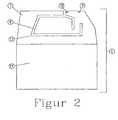
- FIG 2shows the PIFA antenna (6) of the mobile telephone (1), comprising a radiator (7) from sheet metal and a ground surface (11).
- the radiator (7)is connected to the mobile telephone electronics at the feed point (9) and forms a stub with a ground connection (10).
- the current distribution while transmitting in the 900 MHz bandis shown in figure 3 and in the 1800 MHz band in figure 4.
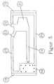
- the condenser plate (21)is located on the first side (19) of the circuit board, which is closest to the mobile telephone (1) when this is placed near the adapter antenna (2).
- the condenser plate (21)has two horns (22 and 23) of conductive material, covering the high current density regions close to the feed point (9) and the stub (10) of the PIFA antenna (6). In another embodiment not shown here, separate but electrically connected plates are located over the high current regions.
- the conductor (24)is located above the slot (8) so as not to be noticably influenced by the currents in the antenna (6).
- the ground plane of the adapter antennais located, comprising a ground plane island (28) and a ground plane loop (29).
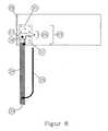
- a transfer (25)consisting of a coplanar waveguide (26) comprising a solder island (27) and ground plane islands (30 and 31), as well as a condenser towards ground, comprising a solder island (27) and a ground plane island (28).
- This condenserwill compensate the inductance of the conductor (24).
- the transfer (25)provides adapting to a 50 ohm coaxial cable.
- the other end (3) of the coaxial cablemay be connected to a second antenna (4) or to an amplifier unit not shown in the figure.
- Currents in the shield (34) of the coaxial cable (33)can be suppressed by means of a quarter wave trap (35). For use with several frequency bands, several wave traps may be supplied. Another possibility is to use a loss means, such as a ferrite ring, to extinguish any wave that could follow the outside of the shield.
- Optimizing the dimensions of the patternshould be made in such a way that not only provides a good transmission from the PIFA antenna (6) to the adapter antenna (2) as well as in the other direction, but also fulfills the demand that the impedance of the PIFA antenna in the feed point (9) should be influenced as little as possible.
Landscapes
- Engineering & Computer Science (AREA)
- Computer Networks & Wireless Communication (AREA)
- Remote Sensing (AREA)
- Signal Processing (AREA)
- Waveguide Aerials (AREA)
- Details Of Aerials (AREA)
- Support Of Aerials (AREA)
Description
- The invention concerns an adapter antenna which without contact can receive andtransfer an electromagnatic wave within the near field of another antenna. The most commonapplication of an adapter antenna is for connection of a mobile telephone which temporarily is usedwithin a vehicle to an external antenna located on the outside of the vehicle.
- All mobile telephones are provided with a built-on first antenna, but not all models areprovided with a coaxial outlet for connection to an external second antenna. If one wishes to use anexternal antenna with a mobile telephone lacking such an antenna outlet, an adapter antenna can belocated near the first antenna and connected by a coaxial cable (33) to the second antenna.
- In the following will be described what is peculiar for an adapter antenna compared toother antennae in general. Antennae are usually located in the far field of a first antenna, where thewave front is approximatively flat with the electric and magnetic field vectors at right angles to eachother. In this case, the antennae do not influence the current distribution of each other, and they maybe designed independently of each other. An adapter antenna is located close to a first antenna in thenear field of this. The electric and magnetic field vectors are here generally not at right angles to eachother. The current distributions of the first antenna and the adapter antenna will influence each other.In an ideal case the transfer between the first antenna and the adapter antenna should be total, and allpower from the first antenna should be collected by the adapter antenna, which in practise can neverbe acheived. In case of use in a vehicle, the non-transferred power will radiate into the vehicle. This isa great disadvantage, the radiation has not fully recognized biological effects which were the reasonfor deciding to use an external antenna. These decribed conditions, which are specific for adapterantenna compared to other types of antennae, mean that adapter antennae should be individuallyoptimized for each type of first antenna. The optimizing may be more difficult if the telephone is ofmultiple N-band type, where N is larger than 1.
- The most common type of antenna for mobile telephones is monopole or small helix.Adapter antella for such are known in from patents US 422095, GB 2266997, SE 50393U, US 577585,SE 504343, WO98/25323. These all use a coil as a coupling element. Adapter antennae suitable alsofor other types of telephone antennae can be shaped as meander convolutions as described in patentsSE 506726 and SE 507100.
- The document D1 EP-A-0 999 607, discloses an antenna coupler for coupling a radiotelecommunication device with an integral planar antenna to an external device. The intergral planarantenna of the radio telecommunication device comprises a first planar conductive antenna element.The antenna coupler comprises a second planar conductive antenna element which is essentiallysimilar to the first planar conductive antenna element, a first conductive ground plane parallel to saidsecond planar conductive antenna element and transmission means for conducting a radio frequencysignal between said second planar conductive antenna element and the external device.
- The document EP-A-1 006 606, cited by the Examiner, discloses a holder and a methodfor transferring signals between apparatus and holder. The invention relates to a holder for a handheldapparatus for emitting radio signals, said apparatus comprising a patch-antenna. The holder comprisesa patch antenna which is adapted to cooperate with the corresponding patch antenna on an apparatusplaced in the holder.
- The known types of adapter antennae are not optimal for certain types of first antennae,such as inverted L, E and F(PIFA) antennae. Coils are less suitable for adapter antennae to these. Oneaim of the invention is to acheive an optimal solution by utilizing the electric field component,implying acting as a condenser together with a suitable adaptive circuit. The invention can be used forsingle as well as multiple frequency band adapter antennae.
- The optimizing is made in the following steps:
- Determine the smallest condenser plate which can efficiently transfer the power.This is made by calculating or measuring the current distribution of the firstantenna and determining the surface or surfaces where the current density is large, and designing the condenser plate of the adapter antenna to have acorresponding surface.
- Choose feed point and means for matching the impedance of the coaxial cable,such as 50 ohm. At the other end of the coaxial cable the second antenna or aamplifier unit may be connected.
- Provide a suitable ground plane, such as a loop around the condenser plate.
- Optimize the adapter antenna while accounting for its influence upon theadaptation of the first antenna in its feed point.
- Fig. 1
- Mobile telephone with a built-in antenna, and an adapter antenna with a cable toan external antenna.
- Fig. 2
- PIFA-antenna for two frequency bands.
- Fig. 3
- Current distribution on a PIFA antenna at 900 MHz.
- Fig. 4
- Current distribution on a PIFA antenna at 1800 MHz.
- Fig. 5
- Pattern on the first side of the circuit board.
- Fig. 6
- Pattern on the second side of the circuit board.
- In the following the invention will be described in the context of an adapterantenna of a preferred type for use with a mobile telephone (1) with a built-in PIFA antenna(6) as seen in figure 2. The components of the adapter antenna (2) are located on a circuitboard (19,20) with circuit patterns of conductive metal on both sides. Alternativeembodiments, not shown in a figure, may be circuit boards with conductive pattern on oneside only, or metal foil conductors, or plastic boards with conductive surface patterns appliedby metallizing, metal spraying, conductive paint or foil. The adaptive circuit at the port (32) isalso located on the circuit board in the version shown by figures 5 and 6. Other designs ofadaptive circuits with discrete or continuous components are commonly known and will notbe discussed here.
- Figure 2 shows the PIFA antenna (6) of the mobile telephone (1), comprising aradiator (7) from sheet metal and a ground surface (11). In the radiator (7) is a cut-out slot (8).The radiator (7) is connected to the mobile telephone electronics at the feed point (9) andforms a stub with a ground connection (10). The current distribution while transmitting in the900 MHz band is shown in figure 3 and in the 1800 MHz band in figure 4. As was explainedin the description of the method of the invention it is desired to have as small a condenserplate as possible in the adapter antenna, though large enough to cover the most active regionsof the PIFA antenna.. In the 1800 MHz band these are close to the feed point (9) and the stub(10). The same holds for the 900 MHz band but then there is also a region at the corner (12) ofthe slot (8). It is, however, best to avoid using the field in the vicinity of the corner (12) sincethat would need a condenser plate too large for 1800 Mhz.
- This results in a design of the condenser plate (21) as shown in figure 5. Thecondenser plate (21) is located on the first side (19) of the circuit board, which is closest to themobile telephone (1) when this is placed near the adapter antenna (2). The condenser plate(21) has two horns (22 and 23) of conductive material, covering the high current densityregions close to the feed point (9) and the stub (10) of the PIFA antenna (6). In anotherembodiment not shown here, separate but electrically connected plates are located over thehigh current regions. The conductor (24) is located above the slot (8) so as not to be noticablyinfluenced by the currents in the antenna (6).
- On the first side (19) of the circuit board the ground plane of the adapter antennais located, comprising a ground plane island (28) and a ground plane loop (29).
- On the other side (21) of the circuit board, shown in figure 6, is a transfer (25)consisting of a coplanar waveguide (26) comprising a solder island (27) and ground planeislands (30 and 31), as well as a condenser towards ground, comprising a solder island (27)and a ground plane island (28). This condenser will compensate the inductance of theconductor (24). The transfer (25) provides adapting to a 50 ohm coaxial cable. The other end(3) of the coaxial cable may be connected to a second antenna (4) or to an amplifier unit notshown in the figure. Currents in the shield (34) of the coaxial cable (33) can be suppressed bymeans of a quarter wave trap (35). For use with several frequency bands, several wave trapsmay be supplied. Another possibility is to use a loss means, such as a ferrite ring, toextinguish any wave that could follow the outside of the shield.
- Optimizing the dimensions of the pattern should be made in such a way that notonly provides a good transmission from the PIFA antenna (6) to the adapter antenna (2) aswell as in the other direction, but also fulfills the demand that the impedance of the PIFAantenna in the feed point (9) should be influenced as little as possible.
- Mobile telephone
- 1
- Adapter antenna
- 2
- Coaxial cable
- 3
- External antenna
- 4
- PIFA antenna
- 6
- Radiator
- 7
- Slot
- 8
- Feed point
- 9
- Stub
- 10
- Ground plane
- 11
- Corner of slot
- 12
- Circuit board, first side
- 19
- Circuit board, second side
- 20
- Condenser plate
- 21
- First horn
- 22
- Second horn
- 23
- Conductor
- 24
- Transfer
- 25
- Coplanar wave guide
- 26
- Solder island
- 27
- Ground plane island
- 28
- Ground loop
- 29
- Ground plane island
- 30
- Ground plane island
- 31
- Port
- 32
- Coaxial cable
- 33
- Shield
- 34
- Wave trap
- 35
- Adapter
- 36
Claims (12)
- Adapter antenna (2) for contact-less transfer of electromagnetic waves within nfrequency bands; wherein n≥1, between a first antenna (6) of plane inverted L, E or F typebuilt into a mobile telephone (1) by means of a condenser plate (21, 22, 23) built intothe adapter antenna (2) and a port (32) of the adapter antenna (2) where a coaxial cable (3) canbe connected which connect the adapter antenna (2) with an outer, second antenna or anamplifier,characterized in that the condenser plate (21, 22, 23) is parallel to and situatedclose to a conductive surface of the first antenna (6) andin that the condenser plate(21, 22, 23) is shaped to cover surfaces close to a feed point (9) and a stub (10) of the firstantenna (6) and those regions of the radiating metal surface of the first antenna (6) where thesurface currents are relatively great in any of the n frequency bands, in order to utilize mainly theelectric component of the near field of the first antenna for the contact-less transfer.
- Adapter antenna (2) according to claim 1, supplemented with a ground planecomprising a ground plane island (28) and a ground plane loop (29), located outside of thecondenser plate (21, 22, 23).
- Adapter antenna (2) according to claim 1 or 2,characterized in that the adapterantenna (2) is provided with a conductor (24) which is located opposite a slot (8) of the firstantenna (6) and is connected to the condenser plate (21, 22, 23).
- Adapter antenna (2) according to claim 1, where the matching unit at theport (32) comprises a coplanar waveguide (26) and a condenser towards ground(27,28).
- Adapter antenna (2) according to claim 1 or 4, where the ground plane (28)is augmented by conductive ribbons (29) or wires, or strips of conductive material followingthe edges of the component (19) carrying the condenser plate (21).
- Adapter antenna (2) according to claims 1,4 or 5, where theconductive surfaces are located on a circuit board.
- Adapter antenna (2) according to claims 1,4,5 or 6, where theconductive surfaces are made of sheet metal.
- Adapter antenna (2) according to one of claims 1 and 4-7, where theconductive surfaces are made by metallizing of plastics.
- Adapter antenna (2) according to one of claims 1 and 4-8, where theconductive surfaces consist of conductive paint.
- Adapter antenna (2) according to one of claims 1 and 4-9, wherethe conductive surfaces are made from foil.
- Adapter antenna (2) according to one of claims 1 and 4-10, where thecoaxial cable (33) is provided with a wave trap (35) which suppresses currents in the shield(34) of the cable.
- Adapter antenna (2) according to one of claims 1 and 4-11, where thecoaxial cable (33) is provided with a component with high internal loss, which suppressescurrents in the shield (34) of the cable.
Applications Claiming Priority (2)
| Application Number | Priority Date | Filing Date | Title |
|---|---|---|---|
| SE0002575 | 2000-07-07 | ||
| SE0002575ASE523526C2 (en) | 2000-07-07 | 2000-07-07 | Adapter antenna designed to interact electromagnetically with an antenna built into a mobile phone |
Publications (2)
| Publication Number | Publication Date |
|---|---|
| EP1170822A1 EP1170822A1 (en) | 2002-01-09 |
| EP1170822B1true EP1170822B1 (en) | 2005-04-13 |
Family
ID=20280416
Family Applications (1)
| Application Number | Title | Priority Date | Filing Date |
|---|---|---|---|
| EP01850119AExpired - LifetimeEP1170822B1 (en) | 2000-07-07 | 2001-07-05 | Adapter antenna for mobile phones |
Country Status (4)
| Country | Link |
|---|---|
| US (1) | US6538607B2 (en) |
| EP (1) | EP1170822B1 (en) |
| DE (1) | DE60109995T2 (en) |
| SE (1) | SE523526C2 (en) |
Cited By (11)
| Publication number | Priority date | Publication date | Assignee | Title |
|---|---|---|---|---|
| US8466756B2 (en) | 2007-04-19 | 2013-06-18 | Pulse Finland Oy | Methods and apparatus for matching an antenna |
| US8473017B2 (en) | 2005-10-14 | 2013-06-25 | Pulse Finland Oy | Adjustable antenna and methods |
| US8564485B2 (en) | 2005-07-25 | 2013-10-22 | Pulse Finland Oy | Adjustable multiband antenna and methods |
| US8618990B2 (en) | 2011-04-13 | 2013-12-31 | Pulse Finland Oy | Wideband antenna and methods |
| US8629813B2 (en) | 2007-08-30 | 2014-01-14 | Pusle Finland Oy | Adjustable multi-band antenna and methods |
| US8648752B2 (en) | 2011-02-11 | 2014-02-11 | Pulse Finland Oy | Chassis-excited antenna apparatus and methods |
| US8786499B2 (en) | 2005-10-03 | 2014-07-22 | Pulse Finland Oy | Multiband antenna system and methods |
| US8847833B2 (en) | 2009-12-29 | 2014-09-30 | Pulse Finland Oy | Loop resonator apparatus and methods for enhanced field control |
| US9406998B2 (en) | 2010-04-21 | 2016-08-02 | Pulse Finland Oy | Distributed multiband antenna and methods |
| US9450291B2 (en) | 2011-07-25 | 2016-09-20 | Pulse Finland Oy | Multiband slot loop antenna apparatus and methods |
| US9673507B2 (en) | 2011-02-11 | 2017-06-06 | Pulse Finland Oy | Chassis-excited antenna apparatus and methods |
Families Citing this family (39)
| Publication number | Priority date | Publication date | Assignee | Title |
|---|---|---|---|---|
| US20010011224A1 (en)* | 1995-06-07 | 2001-08-02 | Stephen James Brown | Modular microprocessor-based health monitoring system |
| SE524825C2 (en)* | 2001-03-07 | 2004-10-12 | Smarteq Wireless Ab | Antenna coupling device cooperating with an internal first antenna arranged in a communication device |
| DE10131335A1 (en)* | 2001-06-28 | 2003-01-09 | Bisplinghoff Gisela | Adapter for a handsfree phone holder |
| FI115803B (en)* | 2002-12-02 | 2005-07-15 | Filtronic Lk Oy | Arrangement for connecting an additional antenna to a radio |
| USD488148S1 (en) | 2002-12-23 | 2004-04-06 | Cingular Wireless, Llc | Auxiliary antenna for a fixed antenna handset |
| USD495686S1 (en) | 2003-04-30 | 2004-09-07 | Cingular Wireless, Llc | Auxiliary antenna for an internal antenna handset |
| FI115172B (en) | 2003-07-24 | 2005-03-15 | Filtronic Lk Oy | Antenna arrangement for connecting an external device to a radio device |
| SE0502225L (en)* | 2005-10-10 | 2006-10-17 | Amc Centurion Ab | Antenna device |
| USD564520S1 (en)* | 2006-02-06 | 2008-03-18 | Microsoft Corporation | Housing for an electronic device |
| US7930814B2 (en)* | 2006-07-26 | 2011-04-26 | Raytheon Company | Manufacturing method for a septum polarizer |
| KR20140066264A (en)* | 2006-11-16 | 2014-05-30 | 갈트로닉스 코포레이션 리미티드 | Compact antenna |
| CN101217213B (en)* | 2007-12-26 | 2012-05-23 | 蒋小平 | Automobile top-mounted antenna device |
| FI20096134A0 (en) | 2009-11-03 | 2009-11-03 | Pulse Finland Oy | Adjustable antenna |
| FI20096251A0 (en) | 2009-11-27 | 2009-11-27 | Pulse Finland Oy | MIMO antenna |
| EP2534759B1 (en) | 2010-02-13 | 2013-11-13 | Peiker acustic GmbH & Co. KG | Arrangement for coupling a mobile phone to an external antenna |
| FI20105158L (en) | 2010-02-18 | 2011-08-19 | Pulse Finland Oy | ANTENNA EQUIPPED WITH SHELL RADIATOR |
| JP4875176B2 (en)* | 2010-02-19 | 2012-02-15 | 株式会社東芝 | Antenna and coupler |
| US8559869B2 (en) | 2011-09-21 | 2013-10-15 | Daniel R. Ash, JR. | Smart channel selective repeater |
| WO2012093391A2 (en) | 2011-01-03 | 2012-07-12 | Galtronics Corporation Ltd. | Compact broadband antenna |
| FI20115072A0 (en) | 2011-01-25 | 2011-01-25 | Pulse Finland Oy | Multi-resonance antenna, antenna module and radio unit |
| US8866689B2 (en) | 2011-07-07 | 2014-10-21 | Pulse Finland Oy | Multi-band antenna and methods for long term evolution wireless system |
| US9123990B2 (en) | 2011-10-07 | 2015-09-01 | Pulse Finland Oy | Multi-feed antenna apparatus and methods |
| US9531058B2 (en) | 2011-12-20 | 2016-12-27 | Pulse Finland Oy | Loosely-coupled radio antenna apparatus and methods |
| US9484619B2 (en) | 2011-12-21 | 2016-11-01 | Pulse Finland Oy | Switchable diversity antenna apparatus and methods |
| US8988296B2 (en) | 2012-04-04 | 2015-03-24 | Pulse Finland Oy | Compact polarized antenna and methods |
| US9979078B2 (en) | 2012-10-25 | 2018-05-22 | Pulse Finland Oy | Modular cell antenna apparatus and methods |
| US10069209B2 (en) | 2012-11-06 | 2018-09-04 | Pulse Finland Oy | Capacitively coupled antenna apparatus and methods |
| US10079428B2 (en) | 2013-03-11 | 2018-09-18 | Pulse Finland Oy | Coupled antenna structure and methods |
| US9647338B2 (en) | 2013-03-11 | 2017-05-09 | Pulse Finland Oy | Coupled antenna structure and methods |
| US9634383B2 (en) | 2013-06-26 | 2017-04-25 | Pulse Finland Oy | Galvanically separated non-interacting antenna sector apparatus and methods |
| US9680212B2 (en) | 2013-11-20 | 2017-06-13 | Pulse Finland Oy | Capacitive grounding methods and apparatus for mobile devices |
| US9590308B2 (en) | 2013-12-03 | 2017-03-07 | Pulse Electronics, Inc. | Reduced surface area antenna apparatus and mobile communications devices incorporating the same |
| US9350081B2 (en) | 2014-01-14 | 2016-05-24 | Pulse Finland Oy | Switchable multi-radiator high band antenna apparatus |
| US9948002B2 (en) | 2014-08-26 | 2018-04-17 | Pulse Finland Oy | Antenna apparatus with an integrated proximity sensor and methods |
| US9973228B2 (en) | 2014-08-26 | 2018-05-15 | Pulse Finland Oy | Antenna apparatus with an integrated proximity sensor and methods |
| US9722308B2 (en) | 2014-08-28 | 2017-08-01 | Pulse Finland Oy | Low passive intermodulation distributed antenna system for multiple-input multiple-output systems and methods of use |
| US9906260B2 (en) | 2015-07-30 | 2018-02-27 | Pulse Finland Oy | Sensor-based closed loop antenna swapping apparatus and methods |
| WO2018126247A2 (en) | 2017-01-02 | 2018-07-05 | Mojoose, Inc. | Automatic signal strength indicator and automatic antenna switch |
| TWI889172B (en)* | 2024-01-26 | 2025-07-01 | 飛捷科技股份有限公司 | External antenna kit |
Family Cites Families (13)
| Publication number | Priority date | Publication date | Assignee | Title |
|---|---|---|---|---|
| US4220955A (en) | 1979-05-29 | 1980-09-02 | Rockwell International Corporation | RF coupling device for connecting a hand held radio to an external device without removing the antenna |
| FR2519474B1 (en)* | 1982-01-05 | 1985-09-20 | Cables De Lyon Geoffroy Delore | DEVICE FOR PROTECTING A COAXIAL CABLE AGAINST LOW FREQUENCY AND HIGH POWER INTERFERENCE PULSES |
| FI84536C (en)* | 1989-05-22 | 1991-12-10 | Nokia Mobira Oy | RF connectors for connecting a radio telephone to an external antenna |
| GB2266997A (en)* | 1992-05-07 | 1993-11-17 | Wallen Manufacturing Limited | Radio antenna. |
| SE503930C2 (en)* | 1994-12-19 | 1996-09-30 | Allgon Ab | Wireless phone adapter |
| US5557287A (en) | 1995-03-06 | 1996-09-17 | Motorola, Inc. | Self-latching antenna field coupler |
| JP3521019B2 (en) | 1995-04-08 | 2004-04-19 | ソニー株式会社 | Antenna coupling device |
| US5668561A (en)* | 1995-11-13 | 1997-09-16 | Motorola, Inc. | Antenna coupler |
| US5852421A (en) | 1996-04-02 | 1998-12-22 | Qualcomm Incorporated | Dual-band antenna coupler for a portable radiotelephone |
| DK176625B1 (en)* | 1996-07-05 | 2008-12-01 | Ipcom Gmbh & Co Kg | Handheld device with antenna means for transmitting a radio signal |
| US5918189A (en)* | 1996-09-30 | 1999-06-29 | Nokia Mobile Phones, Ltd. | Exchangeable hardware module for radiotelephone |
| US6239769B1 (en) | 1996-12-18 | 2001-05-29 | Smarteq Wireless Ab | Antenna connector |
| FI106077B (en)* | 1998-11-04 | 2000-11-15 | Nokia Mobile Phones Ltd | Antenna connector and arrangement for connecting a radio telecommunication device to external devices |
- 2000
- 2000-07-07SESE0002575Apatent/SE523526C2/ennot_activeIP Right Cessation
- 2001
- 2001-07-05EPEP01850119Apatent/EP1170822B1/ennot_activeExpired - Lifetime
- 2001-07-05DEDE60109995Tpatent/DE60109995T2/ennot_activeExpired - Fee Related
- 2001-07-09USUS09/900,455patent/US6538607B2/ennot_activeExpired - Fee Related
Cited By (12)
| Publication number | Priority date | Publication date | Assignee | Title |
|---|---|---|---|---|
| US8564485B2 (en) | 2005-07-25 | 2013-10-22 | Pulse Finland Oy | Adjustable multiband antenna and methods |
| US8786499B2 (en) | 2005-10-03 | 2014-07-22 | Pulse Finland Oy | Multiband antenna system and methods |
| US8473017B2 (en) | 2005-10-14 | 2013-06-25 | Pulse Finland Oy | Adjustable antenna and methods |
| US8466756B2 (en) | 2007-04-19 | 2013-06-18 | Pulse Finland Oy | Methods and apparatus for matching an antenna |
| US8629813B2 (en) | 2007-08-30 | 2014-01-14 | Pusle Finland Oy | Adjustable multi-band antenna and methods |
| US8847833B2 (en) | 2009-12-29 | 2014-09-30 | Pulse Finland Oy | Loop resonator apparatus and methods for enhanced field control |
| US9406998B2 (en) | 2010-04-21 | 2016-08-02 | Pulse Finland Oy | Distributed multiband antenna and methods |
| US8648752B2 (en) | 2011-02-11 | 2014-02-11 | Pulse Finland Oy | Chassis-excited antenna apparatus and methods |
| US9673507B2 (en) | 2011-02-11 | 2017-06-06 | Pulse Finland Oy | Chassis-excited antenna apparatus and methods |
| US9917346B2 (en) | 2011-02-11 | 2018-03-13 | Pulse Finland Oy | Chassis-excited antenna apparatus and methods |
| US8618990B2 (en) | 2011-04-13 | 2013-12-31 | Pulse Finland Oy | Wideband antenna and methods |
| US9450291B2 (en) | 2011-07-25 | 2016-09-20 | Pulse Finland Oy | Multiband slot loop antenna apparatus and methods |
Also Published As
| Publication number | Publication date |
|---|---|
| US20020063659A1 (en) | 2002-05-30 |
| SE0002575D0 (en) | 2000-07-07 |
| EP1170822A1 (en) | 2002-01-09 |
| DE60109995T2 (en) | 2006-02-23 |
| DE60109995D1 (en) | 2005-05-19 |
| SE0002575L (en) | 2002-01-08 |
| US6538607B2 (en) | 2003-03-25 |
| SE523526C2 (en) | 2004-04-27 |
Similar Documents
| Publication | Publication Date | Title |
|---|---|---|
| EP1170822B1 (en) | Adapter antenna for mobile phones | |
| US6603430B1 (en) | Handheld wireless communication devices with antenna having parasitic element | |
| EP0697139B1 (en) | Hand-held transmitting and/or receiving apparatus | |
| KR100621335B1 (en) | Apparatus for Reducing Ground Effects in a Folder-Type Communication Handset Device | |
| US5668561A (en) | Antenna coupler | |
| AU2007294762B2 (en) | Printed circuit notch antenna | |
| KR100625121B1 (en) | Method and Apparatus for Reducing SAR Exposure in a Communication Handset Device | |
| EP0823748A2 (en) | Antenna | |
| CN1291363A (en) | Dual frequency band diversity antenna having papasitic rediating element | |
| EP1310014B1 (en) | Wireless terminal | |
| US6762724B2 (en) | Build-in antenna for a mobile communication terminal | |
| US20060181475A1 (en) | UWB antenna with unidirectional radiation pattern | |
| FI118069B (en) | Grounding device for a device using wireless data transmission | |
| EP0793293B1 (en) | Antenna unit | |
| US20020123312A1 (en) | Antenna systems including internal planar inverted-F Antenna coupled with external radiating element and wireless communicators incorporating same | |
| US7598912B2 (en) | Planar antenna structure | |
| KR101321537B1 (en) | Antenna, manufacturing method thereof, and mobile communication terminal using the same | |
| US7466273B2 (en) | Multiband antenna using whip having independent power feeding in wireless telecommunication terminal | |
| EP4475333A1 (en) | Apparatus and methods for inverted-l and inverted-f antennas | |
| US6314275B1 (en) | Hand-held transmitting and/or receiving apparatus | |
| EP3893329B1 (en) | Antenna for sending and/or receiving electromagnetic signals | |
| KR100861865B1 (en) | Wireless terminal | |
| JP3574420B2 (en) | Portable terminal | |
| US5920293A (en) | Radio frequency (RF) antenna coupler with an electrically extended ground plane | |
| CN216529334U (en) | Ultra-wideband antenna and wireless communication device |
Legal Events
| Date | Code | Title | Description |
|---|---|---|---|
| PUAI | Public reference made under article 153(3) epc to a published international application that has entered the european phase | Free format text:ORIGINAL CODE: 0009012 | |
| AK | Designated contracting states | Kind code of ref document:A1 Designated state(s):DE FR GB Kind code of ref document:A1 Designated state(s):AT BE CH CY DE DK ES FI FR GB GR IE IT LI LU MC NL PT SE TR | |
| AX | Request for extension of the european patent | Free format text:AL;LT;LV;MK;RO;SI | |
| 17P | Request for examination filed | Effective date:20020709 | |
| AKX | Designation fees paid | Free format text:DE FR GB | |
| 17Q | First examination report despatched | Effective date:20030710 | |
| GRAP | Despatch of communication of intention to grant a patent | Free format text:ORIGINAL CODE: EPIDOSNIGR1 | |
| GRAS | Grant fee paid | Free format text:ORIGINAL CODE: EPIDOSNIGR3 | |
| GRAA | (expected) grant | Free format text:ORIGINAL CODE: 0009210 | |
| AK | Designated contracting states | Kind code of ref document:B1 Designated state(s):DE FR GB | |
| REG | Reference to a national code | Ref country code:GB Ref legal event code:FG4D | |
| REG | Reference to a national code | Ref country code:IE Ref legal event code:FG4D | |
| REF | Corresponds to: | Ref document number:60109995 Country of ref document:DE Date of ref document:20050519 Kind code of ref document:P | |
| PGFP | Annual fee paid to national office [announced via postgrant information from national office to epo] | Ref country code:GB Payment date:20050615 Year of fee payment:5 | |
| PGFP | Annual fee paid to national office [announced via postgrant information from national office to epo] | Ref country code:DE Payment date:20050701 Year of fee payment:5 | |
| PLBE | No opposition filed within time limit | Free format text:ORIGINAL CODE: 0009261 | |
| STAA | Information on the status of an ep patent application or granted ep patent | Free format text:STATUS: NO OPPOSITION FILED WITHIN TIME LIMIT | |
| 26N | No opposition filed | Effective date:20060116 | |
| EN | Fr: translation not filed | ||
| PG25 | Lapsed in a contracting state [announced via postgrant information from national office to epo] | Ref country code:GB Free format text:LAPSE BECAUSE OF NON-PAYMENT OF DUE FEES Effective date:20060705 | |
| PG25 | Lapsed in a contracting state [announced via postgrant information from national office to epo] | Ref country code:DE Free format text:LAPSE BECAUSE OF NON-PAYMENT OF DUE FEES Effective date:20070201 | |
| GBPC | Gb: european patent ceased through non-payment of renewal fee | Effective date:20060705 | |
| PG25 | Lapsed in a contracting state [announced via postgrant information from national office to epo] | Ref country code:FR Free format text:LAPSE BECAUSE OF NON-PAYMENT OF DUE FEES Effective date:20050731 | |
| PG25 | Lapsed in a contracting state [announced via postgrant information from national office to epo] | Ref country code:FR Free format text:LAPSE BECAUSE OF NON-PAYMENT OF DUE FEES Effective date:20050413 |