EP1168960B1 - Information remote monitor (irm) medical device - Google Patents
Information remote monitor (irm) medical deviceDownload PDFInfo
- Publication number
- EP1168960B1 EP1168960B1EP01906960AEP01906960AEP1168960B1EP 1168960 B1EP1168960 B1EP 1168960B1EP 01906960 AEP01906960 AEP 01906960AEP 01906960 AEP01906960 AEP 01906960AEP 1168960 B1EP1168960 B1EP 1168960B1
- Authority
- EP
- European Patent Office
- Prior art keywords
- data
- patient
- irm
- data transfer
- remote monitor
- Prior art date
- Legal status (The legal status is an assumption and is not a legal conclusion. Google has not performed a legal analysis and makes no representation as to the accuracy of the status listed.)
- Expired - Lifetime
Links
- 230000006854communicationEffects0.000claimsdescription49
- 238000004891communicationMethods0.000claimsdescription49
- 238000012546transferMethods0.000claimsdescription25
- 230000005540biological transmissionEffects0.000claimsdescription17
- 230000007774longtermEffects0.000claimsdescription3
- 238000003032molecular dockingMethods0.000claims2
- 230000002596correlated effectEffects0.000claims1
- 230000000007visual effectEffects0.000claims1
- 230000000747cardiac effectEffects0.000description27
- 238000012544monitoring processMethods0.000description25
- 230000000638stimulationEffects0.000description9
- 238000000034methodMethods0.000description8
- QVGXLLKOCUKJST-UHFFFAOYSA-Natomic oxygenChemical compound[O]QVGXLLKOCUKJST-UHFFFAOYSA-N0.000description7
- 238000007726management methodMethods0.000description7
- 229910052760oxygenInorganic materials0.000description7
- 239000001301oxygenSubstances0.000description7
- 102100026827Protein associated with UVRAG as autophagy enhancerHuman genes0.000description6
- 101710102978Protein associated with UVRAG as autophagy enhancerProteins0.000description6
- 238000012545processingMethods0.000description6
- 238000010586diagramMethods0.000description5
- 230000006870functionEffects0.000description5
- 230000001684chronic effectEffects0.000description4
- 239000003814drugSubstances0.000description4
- 229940079593drugDrugs0.000description4
- 230000000004hemodynamic effectEffects0.000description4
- 238000012360testing methodMethods0.000description4
- 238000002560therapeutic procedureMethods0.000description4
- 230000036284oxygen consumptionEffects0.000description3
- 206010007559Cardiac failure congestiveDiseases0.000description2
- 208000017667Chronic DiseaseDiseases0.000description2
- 208000001871TachycardiaDiseases0.000description2
- 238000013528artificial neural networkMethods0.000description2
- 208000006218bradycardiaDiseases0.000description2
- 230000036471bradycardiaEffects0.000description2
- 230000001413cellular effectEffects0.000description2
- 238000013480data collectionMethods0.000description2
- 238000013500data storageMethods0.000description2
- 238000013461designMethods0.000description2
- 238000012377drug deliveryMethods0.000description2
- 230000000694effectsEffects0.000description2
- 230000036541healthEffects0.000description2
- 239000007943implantSubstances0.000description2
- 230000006794tachycardiaEffects0.000description2
- 240000006240Linum usitatissimumSpecies0.000description1
- 238000013459approachMethods0.000description1
- 230000007175bidirectional communicationEffects0.000description1
- 230000004397blinkingEffects0.000description1
- 238000009534blood testMethods0.000description1
- 229940030602cardiac therapy drugDrugs0.000description1
- 230000000295complement effectEffects0.000description1
- 230000006835compressionEffects0.000description1
- 238000007906compressionMethods0.000description1
- 239000004020conductorSubstances0.000description1
- 238000012937correctionMethods0.000description1
- 230000008878couplingEffects0.000description1
- 238000010168coupling processMethods0.000description1
- 238000005859coupling reactionMethods0.000description1
- 238000001514detection methodMethods0.000description1
- 238000003745diagnosisMethods0.000description1
- 238000002405diagnostic procedureMethods0.000description1
- 201000010099diseaseDiseases0.000description1
- 208000037265diseases, disorders, signs and symptomsDiseases0.000description1
- 230000002526effect on cardiovascular systemEffects0.000description1
- 238000011156evaluationMethods0.000description1
- 239000012464large bufferSubstances0.000description1
- 210000003205muscleAnatomy0.000description1
- 230000001537neural effectEffects0.000description1
- 230000000926neurological effectEffects0.000description1
- 230000003287optical effectEffects0.000description1
- 210000000056organAnatomy0.000description1
- 230000000737periodic effectEffects0.000description1
- 238000002360preparation methodMethods0.000description1
- 230000008569processEffects0.000description1
- 238000011084recoveryMethods0.000description1
- 230000036279refractory periodEffects0.000description1
- 238000011160researchMethods0.000description1
- 238000012552reviewMethods0.000description1
- 230000006641stabilisationEffects0.000description1
- 238000011105stabilizationMethods0.000description1
- 230000001360synchronised effectEffects0.000description1
- 230000001960triggered effectEffects0.000description1
Images


Classifications
- A—HUMAN NECESSITIES
- A61—MEDICAL OR VETERINARY SCIENCE; HYGIENE
- A61B—DIAGNOSIS; SURGERY; IDENTIFICATION
- A61B5/00—Measuring for diagnostic purposes; Identification of persons
- A61B5/0002—Remote monitoring of patients using telemetry, e.g. transmission of vital signals via a communication network
- A—HUMAN NECESSITIES
- A61—MEDICAL OR VETERINARY SCIENCE; HYGIENE
- A61B—DIAGNOSIS; SURGERY; IDENTIFICATION
- A61B2560/00—Constructional details of operational features of apparatus; Accessories for medical measuring apparatus
- A61B2560/02—Operational features
- A61B2560/0242—Operational features adapted to measure environmental factors, e.g. temperature, pollution
- A61B2560/0247—Operational features adapted to measure environmental factors, e.g. temperature, pollution for compensation or correction of the measured physiological value
- A61B2560/0257—Operational features adapted to measure environmental factors, e.g. temperature, pollution for compensation or correction of the measured physiological value using atmospheric pressure
- Y—GENERAL TAGGING OF NEW TECHNOLOGICAL DEVELOPMENTS; GENERAL TAGGING OF CROSS-SECTIONAL TECHNOLOGIES SPANNING OVER SEVERAL SECTIONS OF THE IPC; TECHNICAL SUBJECTS COVERED BY FORMER USPC CROSS-REFERENCE ART COLLECTIONS [XRACs] AND DIGESTS
- Y10—TECHNICAL SUBJECTS COVERED BY FORMER USPC
- Y10S—TECHNICAL SUBJECTS COVERED BY FORMER USPC CROSS-REFERENCE ART COLLECTIONS [XRACs] AND DIGESTS
- Y10S128/00—Surgery
- Y10S128/903—Radio telemetry
- Y—GENERAL TAGGING OF NEW TECHNOLOGICAL DEVELOPMENTS; GENERAL TAGGING OF CROSS-SECTIONAL TECHNOLOGIES SPANNING OVER SEVERAL SECTIONS OF THE IPC; TECHNICAL SUBJECTS COVERED BY FORMER USPC CROSS-REFERENCE ART COLLECTIONS [XRACs] AND DIGESTS
- Y10—TECHNICAL SUBJECTS COVERED BY FORMER USPC
- Y10S—TECHNICAL SUBJECTS COVERED BY FORMER USPC CROSS-REFERENCE ART COLLECTIONS [XRACs] AND DIGESTS
- Y10S128/00—Surgery
- Y10S128/904—Telephone telemetry
Definitions
- the present inventiongenerally relates to medical devices. Specifically, the invention relates to an interface device implemented to telemetrically and wirelessly transmit physiologic and cardiac data obtained from one or more implantable medical devices (IMDs). More specifically, the invention relates to an information remote monitor (IRM) medical device, having data communications with the IMDs and a remote computer/server that is accessible by Medtronic, Inc. and other care providers to seamlessly and continuously transfer data and enable remote monitoring and management of patients with chronic disease.
- IRMinformation remote monitor
- the IRMis placed in the patient's home/room to access the IMD and transmit stored data via various data transmission schemes to a remote server or other expert centers.
- the present inventionrelates generally to telemetry systems for uplink and downlink telemetry transmission between at least one implantable medical device and an IRM.
- the IRMis implemented to overcome the problems encountered in providing patient services that are generally limited to in-hospital operations.
- Yet another condition of the prior art practicerequires that a patient visit a clinic center for occasional retrieval of data from the IMD to assess the operation of the device and gather patient history for both clinical and research purposes. Further, if a patient with IMDs is taking a drug, it is often clinically prudent to monitor the dose and its impact on the performance of the IMD. Furthermore, the IMD may be adapted to monitor the patient's drug intake, compliance and effectiveness by directly measuring the dose of the drug in the patient. Normally, such data is acquired by having the patient in a hospital/clinic to download the stored data from the IMD or by direct examination, such as, for example, a blood test. Depending on the frequency of data collection, this procedure of assessing a chronic condition of a patient with IMDs may pose serious difficulty and inconvenience for patients who live in rural areas or have limited mobility.
- a programming headis used for facilitating two-way communication between IMDs and the programmer.
- a programming headis positioned on the patient's body over the IMD side such that one or more antennae within the head can send RF signals to, and receive RF signals from, an antenna disposed within the hermetic enclosure of the IMD or disposed within the connector block of the IMD in accordance with common practice in the art.
- procedures that require downlink and uplink using programmersrequire that the patient be present at the hospital or clinic.
- a programmer of this typeis described in more detail in U.S. Patent No. 5,345,362 issued to Thomas J. Winkler, entitled PORTABLE COMPUTER APPARATUS WITH ARTICULATING DISPLAY PANEL.
- U.S. Patent No. 3,769,965 issued to Raddi et aldiscloses a monitor apparatus for implanted pulse generator. Specifically, a monitor apparatus is disclosed for monitoring electrical stimulation signals due to either natural or artificial electrical stimulation of a body part via a communication link such that the repetition rate of the electrical stimulation signals can be determined.
- the monitor apparatuscomprises the subsystems: a transducer; a communication link or network; and a receiver.
- the transduceris adapted to sense the electrical stimulation signals generated either naturally or by an electronic organ stimulator, such as an implanted cardiac pacer, and to convert the electrical stimulation signals to audible signals such as tone bursts.
- the receiveris adapted to measure the time interval between received tone bursts.
- the receiveris further adapted to display or indicate to an observer the time interval between received tone burst. If desired, the receiver can be adapted to indicate directly the repetition rate of the stimulation signals. The information is then utilized by an observer for diagnostic purposes.
- the monitor apparatusalso includes a test means for testing the integrity of the apparatus including the transducer, the communication link and the receiver.
- U.S. Patent No. 3,885,552 issued to Kennedydiscloses a diagnostic method and system for the detection and transmission of data from a remote location to a central location.
- U.S. Patent No. 4,142,533 issued to Brownlee et aldiscloses a monitoring system for cardiac pacers. It discloses a complete system for telemetering and monitoring the functioning of an implanted pacemaker as well as controlling the testing of the functions from a remotely located central facility is disclosed specifically comprising the provision of capabilities for directly and simultaneously transmitting from the pacer, electrical signals indicative of multiple pacer functions, such as, pacer rate, cell voltage, refractory period, heart rate with pacer inhibited, R-wave level and sensing margin, sensing circuit and other component failure, cardiac electrode lead break, and hermetic integrity.
- the indicative signalsare picked up at the patient's location for local analysis and/or telephonically communicated to a remote central monitoring station.
- the central stationmay control testing of the pacemaker functions by transmitting command signals back telephonically for coupling through cooperating external and implanted inductances or magnetically controlled switches to the implanted pacer circuitry.
- U.S. Patent No. 5,467,773 issued to Bergelson et aldiscloses cardiac pacing remote monitoring system.
- Remote monitoring of cardiac electrical activity and/or pacemakerfunction under extensive control by personnel at a central station over the operation of a monitoring instrument at the patient's home, to thereby reduce reliance on active participation by the patient and to enhance useful information and suppress undesirable information in the signals transmitted between the home monitoring unit and the central station.
- U.S. Patent No. 5,626,630 to Markowitz et aldiscloses a medical telemetry system using an implanted passive transponder.
- the telemetry systemincludes a remote monitoring station, a repeater worn externally by a patient and a quasipassive transponder attached to a device implanted in the patient.
- the remote monitoring stationcommunicates to the repeater to initiate an interrogation routine between the repeater and the transponder to extract patient condition information from the implanted device.
- the repeaterreceives the condition information, it relays it to the remote monitoring station.
- the transponderis specially designed to operate with an extremely low level of power, less than 1 nW/baud, and to be compatible for attachment to existing implanted devices.
- the transpondercan operate at a very high data rate, including a rate of about 100 kbps.
- U.S. Patent No. 5,720,770 to Nappholz et aldiscloses a cardiac stimulation system with enhanced communication and control capability.
- a cardiac stimulation systemwhich delivers long term cardiac therapy without a personal supervision by a physician.
- the systemincludes a cardiac stimulation device implanted in a patient and an external device in constant or periodic communication with the cardiac device.
- the external deviceis used to control the pacemaker operation.
- the external devicereceives updates of the condition of the patient and the operation of the cardiac device and the therapy provided by the cardiac device.
- This informationis transmitted by the external device over a standard telephone network which may consist of hardwired network, a cellular network, or a combination thereof to a remote control device operating near the physician and/or a monitoring station used for monitoring and data logging information from a plurality of patients.
- the cardiac device, through the external devicecan also communicate directly and exchange information with the patient over an RF channel.
- the external devicemay be provided with ground position indication system for locating the patient geographically in an emergency.
- U.S. Patent No. 5,944,659 to Flach et alrelates to architecture for TDMA medical telemetry system.
- a medical telemetry systemis provided for collecting the real-time physiologic data of patients (including ambulatory patients) of a medical facility, and for transferring the data via RF to a real-time data distribution network for monitoring and display.
- the systemincludes battery-powered remote telemeters which attach to respective patients, and which collect and transmit (in data packets) the physiologic data of the patients.
- the remote telemeterscommunicate bi-directionally with a number of ceiling-mounted RF transceivers, referred to as "VCELLs," using a wireless TDMA protocol.
- the VCELLswhich are hardwire-connected to a LAN, forward the data packets received from the telemeters to patient monitoring stations on the LAN.
- the VCELLsare distributed throughout the medical facility such that different VCELLs provide coverage for different patient areas.
- the remote telemeterscontinuously assess the quality of the RF links offered by different nearby VCELLs (by scanning the frequencies on which different VCELLs operate), and connect to those VCELLs which offer the best link conditions.
- each remote telemetermaintains connections with two different VCELLs at-a-time, and transmits all data packets (on different frequencies and during different timeslots) to both VCELLs; the system thereby provides space, time and frequency diversity on wireless data packet transfers from the telemeters.
- the telemeters and VCELLsalso implement a patient location protocol for enabling the monitoring of the locations of individual patients.
- the architecturecan accommodate a large number of patients (e.g., 500 or more) while operating within the transmission power limits of the VHF medical telemetry band.
- U.S. Patent No. 6,073,046 issued to Pattel et aldiscloses a heart monitor system to enable a medical facility, after discharge of a cardiovascular patient, to remain in contact with the patient.
- the patientis provided with a multiple lead EKG terminal spread placed on the body, and the signals therefrom are collected and transmitted. They are transmitted to a remote central location.
- the transmitted EKG datais analyzed. It is compared with normal EKG signals and signals captured in time from the same patient as part of the patient history.
- the evaluationis done through a neural network which forms an output signal automatically or through intervention of a cardiologist sending an alarm condition signal to the patient instructing the patient to get immediate treatment at the patient's location or to otherwise go to a specific medical facility.
- Signal preparationincludes providing EKG signals through a multiplexer, conversation into a digital data, removal of bias signals, stabilization of this EKG base line, compression and data transmission through a modulator.
- the receive signalis reconstructed to provide an EKG signal of the patient which is then evaluated in the neural network.
- transmitterireceiver repeater stations and synchronous satellitesare used to convey these signals.
- U.S. Patent No. 6,162,180 issued to Miesel et aldiscloses a non-invasive cardiac monitoring system and method with communications interface. Specifically, a system and method for determining a patient's cardiac output in a non-invasive manner and transmitting cardiac output data to a remote host processor, a communications system, or a local output device is disclosed.
- a noninvasive cardiac monitoring approachutilizes an implantable medical device coupled to an oxygen sensor. The oxygen sensor provides venous oxygen saturation data to the implantable medical device. An oxygen consumption unit produces oxygen consumption data using air exhaled by a patient.
- a processing unitcalculates a cardiac output result in real-time using the venous oxygen saturation data, the oxygen consumption data, and arterial oxygen saturation data assumed to be about 100% or acquired using a sensor external to the patient.
- the implantable medical devicemay transmit the venous oxygen saturation data to the processing unit using electromagnetic signals or acoustic signals.
- the implantable medical devicemay be a pacemaker, a pacemaker. cardioverter, defibrillator (PCD), an oxygen sensing device, or an implantable hemodynamic monitor.
- the processing unitmay store the cardiac output data/result for a period of time and/or communicate the cardiac output result to the remote host processor substantially in real-time via a communications interface.
- the interfacemay include a modem, a computer interface, a network interface, or a communications system interface, for example.
- the processing unitmay communicate the cardiac output result to the remote host processor in an analog, digital or optical form.
- the IRM of the present inventionis intended to provide means for a patient to transmit data from their residence to a health care provider and/or remote server.
- the designis focused on making the process very easy and automated for the patient.
- the complete system of the IRM in conjunction with a server, a web browser and a remote communication systemallows the patient to stay in their home, thus reducing patient visits to the physician or the hospital, while increasing the level of care at a reduced cost.
- the present inventionrelates to a communications system between one or more implanted devices (IMDs) in a patient and an associated information remote monitor (IRM) located at a distance from the IMDs to enable the transmission of physiologic and cardiac data from at least one of the IMDs.
- IMDsimplanted devices
- IRMinformation remote monitor
- the IRMincludes software adapted to communicate with Chronicle ⁇ which is an implantable hemodynamic monitor.
- the Chronicle ⁇without limitation, stores trend data in a large buffer in RAM with resolution ranges from a few seconds to several minutes, depending on storage time interval.
- the IRMis implemented to collect patient/medical device data in a patient's home for transmission to a remote server or clinician to enable remote and chronic patient monitoring and management.
- the IRMis adapted to download data from an external pressure reference (EPR) simultaneous with downloading data from the Chronicle ⁇ using a wireless telemetry data transfer.
- EPRexternal pressure reference
- the IRMis adapted for connection to a PC to use the PC for data transfer.
- the PCmay be used to control the IRM and program the implanted device thereby implementing the IRM as a programmer.
- the IRMcould transfer EPR and Chronicle ⁇ (IMD) data through the PC to a server or a remote clinical/physician center.
- the IRMmay also, via a modem and other wireless communications media, transfer the data to a server or the remote center.
- the IRMutilizes an integral modem to dial a server and transfer data via FTP, PPP and TC/PIP protocols.
- the IRMincludes various structures to promote ease of use in the home environment. Specifically, ergonomic structures in combination with user interface instructions, displays and audible communication make the IRM a user friendly device for application in the home environment.
- the present inventionrelates to the transmission of physiologic and cardiac data obtained from preferably a Chronicle ⁇ implantable heart monitor to a remote computer or server that is accessible by Medtronic and other care providers.
- the IRMis ergonomically designed for home use and includes a highly simplified but effective user interface to enable the patient to use the device without assistance from others.
- the IRMincludes software that is adaptable to communicate with various types of IMDs, including but not limited to neural implants, drug delivery systems and other medical devices, for the purposes of this disclosure
- the Chronicle ⁇is considered the IMD with which data communication and transmission are effectuated.
- Chronicle ⁇is a hemodynamic monitor and includes circuitry for data storage, recovering and processing of pressure, electrogram, heart rate, core temperature, and activity data. Triggered events cause high resolution data collection that is beat to beat for approximately 18 minutes before and after 6 minutes post event.
- Triggered eventscause high resolution data collection that is beat to beat for approximately 18 minutes before and after 6 minutes post event.
- the bradycardia trigger and tachycardia triggerare automatic, and the patient activated trigger requires the application of the antenna by placing it at the IMD's position in the patient's body.
- a wireless communicationmay be implemented using, for example, various types of RF signals blue tooth or equivalent.
- a communication between the IMD and the IRMcould be via direct antenna placement or telemetrically within a range of a few feet.
- the IMDmay employ, for example, an elongated antenna which projects outward from the housing of the IMD as described in the cited Villaseca et al application, or may employ a coil antenna located external the housing.
- FIG. 1is a simplified schematic diagram representation of a functional uplink and downlink bi-directional communication in accordance with the present invention.
- IMDssuch as IMD 10, 10' and 10" may be implanted in patient 12. It may also be possible for the IMDs to have internal communications, B, B' and B''.
- the IMDsmay consist of cardiac device 10, drug delivery device 10', neurological drug device 10" and many others as may be needed to provide the necessary therapy, diagnosis and clinical care to patient 12.
- IMD 10is also shown to have wireless communication with programmer 11 via wireless telemetry line 18".
- any downlink and uplink operations that implement programmer 11would require the patient to go to the hospital or clinic. This is particularly because programmer 11 is rather robust. Programmer 11 is also expensive and technically complicated to operate, and is not easily adaptable for in-home use by patients.
- the present inventionprovides tailored services that parallel some of the operations of programmer 11 at reduced cost and in user friendly settings
- programmer 11after an uplink or downlink could communicate via communication lines 15 with PC 17 or with a Medtronic server 21 via link 19.
- Communication lines 15 and 19represent, without limitation, a modem, an ISDN line, cable, RF, telephone line and may also represent a secure intranet, internet, extranet or World-Wide Web environments to enable data transmission between programmer 11, PC 17 and server/computer 21.
- PC 17which is in bi-directional data communication with server 21 would enable access to stored data and can transfer information between them.
- One aspect of the uplink and downlink operation, using programmer 11,requires either a physician or a technician to be able to operate programmer 11.
- External pressure reference EPR13measures and records barometric pressure which is necessary for correlation to atmospheric pressure.
- the Chronicle ⁇is generally used in patients with chronic CHF, undergoing serial clinical management. It is generally used to complement existing CHF therapies and disease management regimens in order to provide precise therapy management, early intervention by remote monitoring of impending decompensation and to improve quality of life. In this regard, the use of programmer 11 outside the hospital or clinic environment becomes highly impractical.
- IRM 20is shown in data communications with IMD 10.
- IMD 10is implanted in patient 12 beneath the patient's skin or muscle, and is electrically coupled to heart 16 of patient 12 through pace/sense electrodes and lead conductors, or at least one cardiac pacing lead 14 in a manner known in the art.
- IMD 10may represent Chronicle ⁇ which contains an operating system that may employ a microcomputer or a digital state machine for timing, sensing, data storage, recovery and processing of pressure, electrogram, heart rate and other related data, to thereby monitor the hemodynamic environment.
- IRM 20includes telemetry hardware and software which implement an automatic gain control, for instance AGC algorithm to a low, easier positioning of antenna 18 by patient 12.
- a wireless communication line 18'could also be implemented.
- the placement of antenna 18 by the patient on IMD 10, without limitation,is considered the preferred procedure to trigger data transfer or uplink.
- IRM 20includes ergonomic features that make it highly compatible for in-home use by a patient.
- the upright shape of IRM 20enables the unit to sit on a counter or on a nightstand.
- the user interface, including a start button,are located in positions which make them highly accessible to the patient.
- IRM 20 and EPR 24are adapted to transfer time stamped long term barometric pressure data to enable correction of cardiac pressure readings due to barometric pressure uplinked from Chronicle ⁇ , (IMD 10) to IRM 20.
- EPR 24is generally carried by patient 12 or a belt implement 32 or is kept in close proximity to patient 12. EPR 24 is used to derive reference pressure data for use in combination with absolute pressure derived from Chronicle ⁇ (IMD 10).
- IMD 10absolute pressure derived from Chronicle ⁇
- IRM 20is shown in telemetry communication with Chronicle ⁇ IMD 10.
- cardiac datais transmitted to IMD 10 via lead 14 as described hereinabove.
- telemetry communicationis established between IMD 10 and IRM 20. Communication could be via antenna 18 or wireless communication such as RF signals 18' as is discussed hereinbelow.
- Patient 12triggers an uplink session by installing EPR 24 in a designated slot and push the start button.
- the microcontroller in IRM 20will look for EPR 24 and if it confirms the existence of EPR 24 it will start downloading barometer data into IRM 20. Thereafter, telemetry is enabled and data will start being transmitted from IMD 10.
- IRM 20When all the data from IMD 10 is telemetered down, then IRM 20 will try to transmit the data out via transmission line 26 which may include a phone line, a cable modem, an ISD line, a cable or equivalent wireless data transmission system to transfer the data to server 30.
- transmission line 26may include a phone line, a cable modem, an ISD line, a cable or equivalent wireless data transmission system to transfer the data to server 30.
- FIG. 3Aa perspective view of IRM 20 is shown with antenna 18, which antenna should be placed at the implant position to enable telemetry link in accordance with one embodiment of the present invention.
- FIG. 3Bis a perspective drawing representing the various structures of IRM 20.
- IRM 20includes back panel 40 with support cradles attached externally thereof.
- Support cradles 50enable to securely stow antenna 18 when not in use.
- aperture 52is designed to allow easy movement and access for cords and wires to connect to a panel behind back panel 40.
- Support structure 42separates back panel 40 and front structure 44.
- support structure 42may be used to store the cord of antenna 18.
- Structure 44represents the side panels that connect the back panels via support structure 42 to the front panel which includes panel 46 and interface panel 48.
- Top structure of IRM 20includes slot 54 fitted for installing EPR 24 in position to download information into IRM 20.
- Button 56is a push down start button that a patient or an operator needs to push in order to initiate the operations of IRM 20.
- IRM 20shown with antenna 18 in stowed position in support cradle 50.
- the power cord for antenna 18is shown pulled through aperture 52 and disposed frontally at panel 40.
- Figure 4Bshows power panel 60 which is disposed behind panel 40.
- Power panel 60includes power plug 62 to which a power cord could be attached to supply power to the IRM.
- Serial port 64is implemented to connect the IRM 20 to PC 27, for example (See Figure 1 or Figure 2).
- Telephone connections 66may be used to connect to a telephone jack and optionally a caller ID box in communication with an answering machine and a telephone.
- Dialing sequence switch 68is placed in either a standard position which is up, or to dial a special number, down.
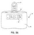
- FIG. 5Ashows EPR 24 poised on top of slot 54 which it must engage to enable download of barometric pressure used for correlation to atmospheric pressure from EPR 24 to IRM 20.
- Figure 5Bshows EPR 24 positioned/engaged in slot 54 to download barometric data into IRM 20.
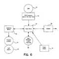
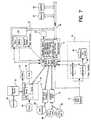
- FIG. 6is a block diagram representing the various components in accordance with the present invention.
- main microcontroller 72is an operable electric communication with EPR interface 74.
- EPR interface 74is located in slots 54 to enable engagement between EPR 24 and IRM 20.
- telemetry board 70is in electrical communication with main microcontroller 72.
- telemetry board 70is connected to flexible antenna 18. As discussed hereinabove, when antenna 18 is placed on implantable medical device such as Chronicle ⁇ , telemetry communication is established. Through this communication, data contained in IMD 10 is transferred to IRM 20.
- main microcontroller 72is connected to a power supply and modem 78 or equivalent.
- User interface LED buttons 48operate via main microcontroller logic as will be discussed hereinbelow.
- EPR serial, interface 74is in operable data communication with microcontroller 72 and EPR connector 80. It should be noted that EPR connector 80 is disposed in slots 54 (See Figure 5A) to engage EPR 24.
- Microprocessor 81is connected to telemetry circuit 82 which in turn is connected to antenna 18.
- Clocks 86 and 88run various functions of microcontroller 81. Further, internal LED are represented by block 84.
- Microcontroller 72is in operable electrical and data communication with microcontroller 81 and clock 88. Further, microcontroller 72 is in data and operable electrical communication with modem 78 which in turn is connected to phone jacks 66.
- Power supply for microcontroller 72includes voltage regulator 83 that regulates modem, memory and the user interface, and voltage regulator 85 which regulates telemetry and related circuits.
- the systemis adapted to use a twelve volt DC as a power supply.
- User interface 90includes front panel LEDs, buttons, speakers and beepers, in addition to LCDs.
- the LCDcould provide a graphic LCD display and actual text.
- the LCDmay also have multilingual programmable text, including help instructions.
- Data bus 98sends data out to memory 94. Similarly, data is sent out to EEPROM 96 via data bus 98.
- Clock 92runs microcontroller 72.
- IRM 20 of the present inventioncould be used as an interface to transfer medical device information via the known wireless communication systems, patient data to remote location for review in chronic monitoring.
- IRM 20operates in conjunction with EPR 24.
- EPR 24is generally worn by the patient or kept in close proximity to monitor environment of biometric pressure.
- IRM 20is connected to a power outlet via connection 62.
- IRM 20may also be connected to a telephone line via telephone connection 66, but this connection is not necessary for the IRM to work properly.
- a dialing sequence switchshould be placed in the right setting. Most homes would use a standard sequence with switch 68 in an up position.
- a green power light on interface panel 48will come on. This green light is an indication that IRM 20 is on.
- EPR 24is placed in slot 54 on top of IRM 20. The patient would then place antenna 18 over IMD 10. While holding antenna 18 over IMD 10, the patient would push start button 56 on top of IRM 20. Thereafter, a green LED will blink indicating that IRM 20 is gathering information from EPR 24 and IMD 10. When data transmission is complete the light will stop blinking and a second green light will come on.
- the second green lightwill start to blink when IRM 20 is transferring data to the remote station. Subsequently, when IRM 20 is done sending information, the second light will turn off and two or more beeps will sound. The patient then will remove EPR 24 from IRM 20 and wear it as a pager or keep it in the vicinity until it is time to use IRM 20 again.
Landscapes
- Health & Medical Sciences (AREA)
- Life Sciences & Earth Sciences (AREA)
- Engineering & Computer Science (AREA)
- Heart & Thoracic Surgery (AREA)
- Molecular Biology (AREA)
- Biophysics (AREA)
- Pathology (AREA)
- Biomedical Technology (AREA)
- Computer Networks & Wireless Communication (AREA)
- Medical Informatics (AREA)
- Physics & Mathematics (AREA)
- Surgery (AREA)
- Animal Behavior & Ethology (AREA)
- General Health & Medical Sciences (AREA)
- Public Health (AREA)
- Veterinary Medicine (AREA)
- Measuring And Recording Apparatus For Diagnosis (AREA)
Description
evaluated in the neural network. As appropriate, transmitterireceiver repeater stations andsynchronous satellites are used to convey these signals.
cardiac output result to the remote host processor substantially in real-time via acommunications interface. The interface may include a modem, a computer interface,a network interface, or a communications system interface, for example. Theprocessing unit may communicate the cardiac output result to the remote host processorin an analog, digital or optical form.
Further, using similar data transmission systems,
Claims (7)
- A remote medical data transfer system in which data from one or more implanted medical devices (10,10', 10") in apatient is transferred to a remote server or physician, the data transfer system comprising:said information remote monitor (20) having engagement means to download said barometric data from the external pressure reference (24)and further implementing the wireless communication to uplink the one or more implanted medical devices (10,10', 10")to transfer patient data in real time and to thereby integrate the patient data and the external pressure reference (24)for transmission to the remote server or physician via said data transfer medium.an information remote monitor (20) in wireless communication with the one or more implanted medical devices (10,10', 10");an external pressure reference (24) containing long term barometric pressure data; anda data transfer medium in operable communications with the information remote monitor (20);
- The data transfer system of claim 1 wherein said information remote monitor (20) includes telemetry hardwareand software and promotes ease of use by the patient.
- The data transfer system of claim 1 wherein said information remote monitor (20) includes an integral modemto dial a server and transfer medical/patient data via FTP, PPP and TC/PIP protocols.
- The data transfer system of claim 1 wherein said external pressure reference (24) engages said information remote monitor (20) via adocking port to allow data from the external pressure reference (24) to be downloaded.
- The data transfer system of claim 4 wherein said docking port is adapted to acceptand cradle said external pressure reference (24) for ease of use by the patient.
- The data transfer system of claim 1 wherein said information remote monitor (20) includes ergonomicstructures.
- The data transfer system of claim 1 wherein said information remote monitor (20) includes a user interfacesystem including visual displays, tones and correlated graphics.
Applications Claiming Priority (3)
| Application Number | Priority Date | Filing Date | Title |
|---|---|---|---|
| US18028500P | 2000-02-04 | 2000-02-04 | |
| US180285P | 2000-02-04 | ||
| PCT/US2001/003589WO2001056467A1 (en) | 2000-02-04 | 2001-02-02 | Information remote monitor (irm) medical device |
Publications (2)
| Publication Number | Publication Date |
|---|---|
| EP1168960A1 EP1168960A1 (en) | 2002-01-09 |
| EP1168960B1true EP1168960B1 (en) | 2004-10-06 |
Family
ID=22659891
Family Applications (1)
| Application Number | Title | Priority Date | Filing Date |
|---|---|---|---|
| EP01906960AExpired - LifetimeEP1168960B1 (en) | 2000-02-04 | 2001-02-02 | Information remote monitor (irm) medical device |
Country Status (4)
| Country | Link |
|---|---|
| US (1) | US6805667B2 (en) |
| EP (1) | EP1168960B1 (en) |
| DE (1) | DE60106141T2 (en) |
| WO (1) | WO2001056467A1 (en) |
Cited By (1)
| Publication number | Priority date | Publication date | Assignee | Title |
|---|---|---|---|---|
| US7555348B1 (en) | 2004-11-19 | 2009-06-30 | Pacesetter, Inc. | Remote transtelephonic monitor user interface |
Families Citing this family (102)
| Publication number | Priority date | Publication date | Assignee | Title |
|---|---|---|---|---|
| US20030036746A1 (en) | 2001-08-16 | 2003-02-20 | Avi Penner | Devices for intrabody delivery of molecules and systems and methods utilizing same |
| US6353761B1 (en)* | 1999-08-20 | 2002-03-05 | Cardiac Pacemakers, Inc. | Cardiac rhythm management system with user interface for threshold test |
| US6622050B2 (en)* | 2000-03-31 | 2003-09-16 | Medtronic, Inc. | Variable encryption scheme for data transfer between medical devices and related data management systems |
| US6735479B2 (en)* | 2000-06-14 | 2004-05-11 | Medtronic, Inc. | Lifestyle management system |
| US7024248B2 (en) | 2000-10-16 | 2006-04-04 | Remon Medical Technologies Ltd | Systems and methods for communicating with implantable devices |
| US20020143576A1 (en)* | 2001-03-28 | 2002-10-03 | Rainer Nolvak | Remote patient health management system |
| JP4498636B2 (en) | 2001-04-27 | 2010-07-07 | 日本サーモスタット株式会社 | Thermostat device |
| US6783492B2 (en)* | 2001-06-26 | 2004-08-31 | Steven Dominguez | System and method for monitoring body functions |
| US20030093503A1 (en)* | 2001-09-05 | 2003-05-15 | Olympus Optical Co., Ltd. | System for controling medical instruments |
| US20030088666A1 (en)* | 2001-11-07 | 2003-05-08 | Engel Glenn R. | Data collection node that utilizes HTTP transfer protocols for autonomous data transfers |
| US7060030B2 (en)* | 2002-01-08 | 2006-06-13 | Cardiac Pacemakers, Inc. | Two-hop telemetry interface for medical device |
| US7261733B1 (en)* | 2002-06-07 | 2007-08-28 | Endovascular Technologies, Inc. | Endovascular graft with sensors design and attachment methods |
| DE10300735A1 (en)* | 2003-01-11 | 2004-07-22 | Corscience Gmbh & Co.Kg | Method for detecting a fibrillation state and device for defibrillation |
| US20040210273A1 (en)* | 2003-04-18 | 2004-10-21 | Medtronic, Inc. | Presentation of patient image with implantable medical device information |
| US7182738B2 (en)* | 2003-04-23 | 2007-02-27 | Marctec, Llc | Patient monitoring apparatus and method for orthosis and other devices |
| US7031745B2 (en)* | 2003-05-12 | 2006-04-18 | Shen Ein-Yiao | Cellular phone combined physiological condition examination and processing device |
| US7462149B2 (en)* | 2003-05-19 | 2008-12-09 | Alcohol Monitoring Systems, Inc. | Method and apparatus for remote blood alcohol monitoring |
| US7311665B2 (en)* | 2003-05-19 | 2007-12-25 | Alcohol Monitoring Systems, Inc. | Bio-information sensor monitoring system and method |
| US7440805B2 (en)* | 2003-07-30 | 2008-10-21 | Cardiac Pacemakers, Inc. | Implantable pulse generator system and method for utilizing communication protocols |
| US20050059867A1 (en)* | 2003-09-13 | 2005-03-17 | Cheng Chung Yuan | Method for monitoring temperature of patient |
| US7617002B2 (en)* | 2003-09-15 | 2009-11-10 | Medtronic, Inc. | Selection of neurostimulator parameter configurations using decision trees |
| US7252090B2 (en) | 2003-09-15 | 2007-08-07 | Medtronic, Inc. | Selection of neurostimulator parameter configurations using neural network |
| US7184837B2 (en) | 2003-09-15 | 2007-02-27 | Medtronic, Inc. | Selection of neurostimulator parameter configurations using bayesian networks |
| US7239926B2 (en) | 2003-09-15 | 2007-07-03 | Medtronic, Inc. | Selection of neurostimulator parameter configurations using genetic algorithms |
| WO2005031632A2 (en)* | 2003-09-24 | 2005-04-07 | Medtronic, Inc. | Apparatus and method for serving medical device application content to a remote computing device |
| US7009494B2 (en)* | 2003-11-21 | 2006-03-07 | Eastman Kodak Company | Media holder having communication capabilities |
| US20070167850A1 (en)* | 2004-01-15 | 2007-07-19 | Russell James K | Adaptive physiological monitoring system and methods of using the same |
| US7330762B2 (en)* | 2004-06-07 | 2008-02-12 | Neuro And Cardiac Technologies, Llc | Method and system for providing pulsed electrical stimulation to provide therapy for erectile/sexual dysfunction, prostatitis, prostatitis pain, and chronic pelvic pain |
| US20050283380A1 (en)* | 2004-06-18 | 2005-12-22 | Garduno Ramon S | Delivery service for a health management system |
| FR2872695B1 (en)* | 2004-07-09 | 2007-10-05 | Hartmann Thierry | ALARM DEVICE FOR PREVENTING SUDDEN INFANT DEATH |
| US8634926B2 (en)* | 2004-09-08 | 2014-01-21 | Medtronic, Inc. | Clinic based instrument system for remote processing and access to implanted systems information |
| US20060064133A1 (en) | 2004-09-17 | 2006-03-23 | Cardiac Pacemakers, Inc. | System and method for deriving relative physiologic measurements using an external computing device |
| US20060064134A1 (en)* | 2004-09-17 | 2006-03-23 | Cardiac Pacemakers, Inc. | Systems and methods for deriving relative physiologic measurements |
| US7840275B2 (en)* | 2004-10-01 | 2010-11-23 | Medtronic, Inc. | In-home remote monitor with smart repeater, memory and emergency event management |
| US7813808B1 (en) | 2004-11-24 | 2010-10-12 | Remon Medical Technologies Ltd | Implanted sensor system with optimized operational and sensing parameters |
| EP1681803A1 (en)* | 2005-01-18 | 2006-07-19 | BIOTRONIK CRM Patent AG | Patient device |
| US20100312129A1 (en) | 2005-01-26 | 2010-12-09 | Schecter Stuart O | Cardiovascular haptic handle system |
| US20060167529A1 (en) | 2005-01-26 | 2006-07-27 | Schecter Stuart O | Method and algorithm for defining the pathologic state from a plurality of intrinsically and extrinsically derived signals |
| US20090030332A1 (en)* | 2005-01-26 | 2009-01-29 | Schecter Stuart O | microfabricated cardiac sensor with tactile feedback and method and apparatus for calibrating the same using a plurality of signals |
| GB0504844D0 (en)* | 2005-03-10 | 2005-04-13 | Zarlink Semiconductor Ab | Radiolink maintenance lock |
| DE102005011667A1 (en)* | 2005-03-14 | 2006-09-28 | Siemens Ag | Medical examination or treatment device, in particular X-ray or CT device |
| US8251904B2 (en) | 2005-06-09 | 2012-08-28 | Roche Diagnostics Operations, Inc. | Device and method for insulin dosing |
| CA2613241A1 (en) | 2005-06-21 | 2007-01-04 | Cardiomems, Inc. | Method of manufacturing implantable wireless sensor for in vivo pressure measurement |
| US7769460B2 (en)* | 2005-07-29 | 2010-08-03 | Medtronic, Inc. | Transmembrane sensing device for sensing bladder condition |
| US7742815B2 (en) | 2005-09-09 | 2010-06-22 | Cardiac Pacemakers, Inc. | Using implanted sensors for feedback control of implanted medical devices |
| US7595723B2 (en) | 2005-11-14 | 2009-09-29 | Edwards Lifesciences Corporation | Wireless communication protocol for a medical sensor system |
| US8634925B2 (en)* | 2005-11-30 | 2014-01-21 | Medtronic, Inc. | Portable programmer for providing patient status information |
| US20070142727A1 (en)* | 2005-12-15 | 2007-06-21 | Cardiac Pacemakers, Inc. | System and method for analyzing cardiovascular pressure measurements made within a human body |
| US20070226013A1 (en)* | 2006-03-07 | 2007-09-27 | Cardiac Pacemakers, Inc. | Method and apparatus for automated generation and transmission of data in a standardized machine-readable format |
| US20090131959A1 (en)* | 2006-04-20 | 2009-05-21 | Liquidia Technologies Inc. | Biological Vessel Flow Control Devices and Methods |
| US7840276B2 (en)* | 2006-04-26 | 2010-11-23 | Medtronic, Inc. | Generic device programmer network interface |
| US7715920B2 (en) | 2006-04-28 | 2010-05-11 | Medtronic, Inc. | Tree-based electrical stimulator programming |
| US8380300B2 (en)* | 2006-04-28 | 2013-02-19 | Medtronic, Inc. | Efficacy visualization |
| US8306624B2 (en) | 2006-04-28 | 2012-11-06 | Medtronic, Inc. | Patient-individualized efficacy rating |
| US20080021521A1 (en)* | 2006-07-18 | 2008-01-24 | Cardiac Pacemakers, Inc. | Implantable Medical Device Communication System |
| US7955268B2 (en) | 2006-07-21 | 2011-06-07 | Cardiac Pacemakers, Inc. | Multiple sensor deployment |
| US10003862B2 (en) | 2007-03-15 | 2018-06-19 | Endotronix, Inc. | Wireless sensor reader |
| US8154389B2 (en) | 2007-03-15 | 2012-04-10 | Endotronix, Inc. | Wireless sensor reader |
| KR20090128499A (en) | 2007-03-19 | 2009-12-15 | 인슐린 메디컬 엘티디 | Drug delivery devices |
| US8622991B2 (en) | 2007-03-19 | 2014-01-07 | Insuline Medical Ltd. | Method and device for drug delivery |
| US9220837B2 (en) | 2007-03-19 | 2015-12-29 | Insuline Medical Ltd. | Method and device for drug delivery |
| EP2231229A1 (en) | 2007-12-18 | 2010-09-29 | Insuline Medical Ltd. | Drug delivery device with sensor for closed-loop operation |
| WO2009102613A2 (en) | 2008-02-11 | 2009-08-20 | Cardiac Pacemakers, Inc. | Methods of monitoring hemodynamic status for ryhthm discrimination within the heart |
| US8369960B2 (en) | 2008-02-12 | 2013-02-05 | Cardiac Pacemakers, Inc. | Systems and methods for controlling wireless signal transfers between ultrasound-enabled medical devices |
| EP2331201B1 (en)* | 2008-10-01 | 2020-04-29 | Inspire Medical Systems, Inc. | System for treating sleep apnea transvenously |
| WO2010042291A1 (en) | 2008-10-10 | 2010-04-15 | Cardiac Pacemakers, Inc. | Systems and methods for determining cardiac output using pulmonary artery pressure measurements |
| CA2743027C (en) | 2008-11-07 | 2016-04-12 | Insuline Medical Ltd. | Device and method for drug delivery |
| JP5575789B2 (en) | 2008-11-19 | 2014-08-20 | インスパイア・メディカル・システムズ・インコーポレイテッド | How to treat sleep-disordered breathing |
| US8632470B2 (en) | 2008-11-19 | 2014-01-21 | Cardiac Pacemakers, Inc. | Assessment of pulmonary vascular resistance via pulmonary artery pressure |
| US8685093B2 (en) | 2009-01-23 | 2014-04-01 | Warsaw Orthopedic, Inc. | Methods and systems for diagnosing, treating, or tracking spinal disorders |
| US8126736B2 (en) | 2009-01-23 | 2012-02-28 | Warsaw Orthopedic, Inc. | Methods and systems for diagnosing, treating, or tracking spinal disorders |
| JP2012521864A (en) | 2009-03-31 | 2012-09-20 | インスパイア・メディカル・システムズ・インコーポレイテッド | Percutaneous access method in a system for treating sleep-related abnormal breathing |
| US8257289B2 (en)* | 2010-02-03 | 2012-09-04 | Tyco Healthcare Group Lp | Fitting of compression garment |
| US10541048B2 (en)* | 2010-02-18 | 2020-01-21 | Siemens Healthcare Gmbh | System for monitoring and visualizing a patient treatment process |
| JP5432767B2 (en)* | 2010-02-25 | 2014-03-05 | 日本光電工業株式会社 | Remote maintenance system and relay unit |
| US20120083712A1 (en) | 2010-09-30 | 2012-04-05 | Tyco Healthcare Group Lp | Monitoring Compliance Using Venous Refill Detection |
| WO2012092197A2 (en) | 2010-12-27 | 2012-07-05 | Medtronic, Inc. | Application limitations for a medical communication module and host device |
| US8942828B1 (en) | 2011-04-13 | 2015-01-27 | Stuart Schecter, LLC | Minimally invasive cardiovascular support system with true haptic coupling |
| US9265958B2 (en) | 2011-04-29 | 2016-02-23 | Cyberonics, Inc. | Implantable medical device antenna |
| US9259582B2 (en) | 2011-04-29 | 2016-02-16 | Cyberonics, Inc. | Slot antenna for an implantable device |
| US9240630B2 (en) | 2011-04-29 | 2016-01-19 | Cyberonics, Inc. | Antenna shield for an implantable medical device |
| US9089712B2 (en) | 2011-04-29 | 2015-07-28 | Cyberonics, Inc. | Implantable medical device without antenna feedthrough |
| USD679813S1 (en)* | 2011-05-19 | 2013-04-09 | Shl Telemedicine International Ltd. | Portable heart monitor |
| US20150039045A1 (en) | 2011-08-11 | 2015-02-05 | Inspire Medical Systems, Inc. | Method and system for applying stimulation in treating sleep disordered breathing |
| US10013082B2 (en) | 2012-06-05 | 2018-07-03 | Stuart Schecter, LLC | Operating system with haptic interface for minimally invasive, hand-held surgical instrument |
| US10206592B2 (en) | 2012-09-14 | 2019-02-19 | Endotronix, Inc. | Pressure sensor, anchor, delivery system and method |
| JP2016516489A (en) | 2013-03-15 | 2016-06-09 | ウィリアム エル ハンター | Apparatus, system and method for monitoring hip replacements |
| CN113274173A (en) | 2013-06-23 | 2021-08-20 | 卡纳里医疗公司 | Devices, systems, and methods for monitoring knee replacements |
| CN103908231A (en)* | 2014-04-25 | 2014-07-09 | 湖南三谊医疗科技有限公司 | Wireless ambulatory blood pressure and pulse monitoring system |
| US20160033308A1 (en)* | 2014-08-04 | 2016-02-04 | Infineon Technologies Ag | Intelligent gauge devices and related systems and methods |
| CA2998709A1 (en) | 2014-09-17 | 2016-03-24 | Canary Medical Inc. | Devices, systems and methods for using and monitoring medical devices |
| WO2016149344A1 (en) | 2015-03-19 | 2016-09-22 | Inspire Medical Systems, Inc. | Stimulation for treating sleep disordered breathing |
| CN113456450B (en) | 2015-10-09 | 2025-01-07 | Kpr美国有限责任公司 | Compression Garment Compliance |
| KR102854603B1 (en) | 2016-03-23 | 2025-09-04 | 카나리 메디칼 아이엔씨. | Implantable reporting processor for an alert implant |
| US11191479B2 (en)* | 2016-03-23 | 2021-12-07 | Canary Medical Inc. | Implantable reporting processor for an alert implant |
| US11615257B2 (en) | 2017-02-24 | 2023-03-28 | Endotronix, Inc. | Method for communicating with implant devices |
| US10430624B2 (en) | 2017-02-24 | 2019-10-01 | Endotronix, Inc. | Wireless sensor reader assembly |
| US10993669B2 (en) | 2017-04-20 | 2021-05-04 | Endotronix, Inc. | Anchoring system for a catheter delivered device |
| CA3069230C (en) | 2017-07-19 | 2024-06-11 | Endotronix, Inc. | Physiological monitoring system |
| US12232985B2 (en) | 2019-06-06 | 2025-02-25 | Canary Medical Inc. | Intelligent joint prosthesis |
| US20210366610A1 (en) | 2019-06-06 | 2021-11-25 | Canary Medical Inc. | Intelligent joint prosthesis |
| CN115514590B (en)* | 2021-06-03 | 2024-01-05 | 台达电子工业股份有限公司 | Electric vehicle component, electric vehicle data collection system and electric vehicle data collection method |
Family Cites Families (20)
| Publication number | Priority date | Publication date | Assignee | Title |
|---|---|---|---|---|
| US3769965A (en) | 1971-02-23 | 1973-11-06 | Esb Inc | Monitor apparatus for implanted pulse generator |
| US3885552A (en) | 1972-11-16 | 1975-05-27 | Pacemaker Diagnostic Clinic Of | Cardiac function monitoring system and method for use in association with cardiac pacer apparatus |
| US4142533A (en) | 1976-10-28 | 1979-03-06 | Research Corporation | Monitoring system for cardiac pacers |
| US5113869A (en) | 1990-08-21 | 1992-05-19 | Telectronics Pacing Systems, Inc. | Implantable ambulatory electrocardiogram monitor |
| US5345362A (en) | 1993-04-29 | 1994-09-06 | Medtronic, Inc. | Portable computer apparatus with articulating display panel |
| US5467773A (en) | 1993-05-21 | 1995-11-21 | Paceart Associates, L.P. | Cardiac patient remote monitoring using multiple tone frequencies from central station to control functions of local instrument at patient's home |
| US5404877A (en) | 1993-06-04 | 1995-04-11 | Telectronics Pacing Systems, Inc. | Leadless implantable sensor assembly and a cardiac emergency warning alarm |
| US5626630A (en) | 1994-10-13 | 1997-05-06 | Ael Industries, Inc. | Medical telemetry system using an implanted passive transponder |
| DE69615007T2 (en) | 1995-02-27 | 2002-06-13 | Medtronic, Inc. | EXTERNAL REFERENCE PROBE FOR A PATIENT |
| US6238338B1 (en)* | 1999-07-19 | 2001-05-29 | Altec, Inc. | Biosignal monitoring system and method |
| US5720770A (en) | 1995-10-06 | 1998-02-24 | Pacesetter, Inc. | Cardiac stimulation system with enhanced communication and control capability |
| US5944659A (en) | 1995-11-13 | 1999-08-31 | Vitalcom Inc. | Architecture for TDMA medical telemetry system |
| US5749900A (en)* | 1995-12-11 | 1998-05-12 | Sulzer Intermedics Inc. | Implantable medical device responsive to heart rate variability analysis |
| US5904708A (en)* | 1998-03-19 | 1999-05-18 | Medtronic, Inc. | System and method for deriving relative physiologic signals |
| US6073046A (en) | 1998-04-27 | 2000-06-06 | Patel; Bharat | Heart monitor system |
| US6152885A (en) | 1998-04-30 | 2000-11-28 | Medtronic, Inc. | Barometric pressure sensor for use with implantable absolute pressure sensor |
| US6162180A (en) | 1998-12-28 | 2000-12-19 | Medtronic, Inc. | Non-invasive cardiac monitoring system and method with communications interface |
| US6416471B1 (en)* | 1999-04-15 | 2002-07-09 | Nexan Limited | Portable remote patient telemonitoring system |
| US6190326B1 (en)* | 1999-04-23 | 2001-02-20 | Medtrac Technologies, Inc. | Method and apparatus for obtaining patient respiratory data |
| US6250309B1 (en)* | 1999-07-21 | 2001-06-26 | Medtronic Inc | System and method for transferring information relating to an implantable medical device to a remote location |
- 2001
- 2001-02-02WOPCT/US2001/003589patent/WO2001056467A1/enactiveIP Right Grant
- 2001-02-02EPEP01906960Apatent/EP1168960B1/ennot_activeExpired - Lifetime
- 2001-02-02USUS09/776,265patent/US6805667B2/ennot_activeExpired - Lifetime
- 2001-02-02DEDE60106141Tpatent/DE60106141T2/ennot_activeExpired - Lifetime
Cited By (1)
| Publication number | Priority date | Publication date | Assignee | Title |
|---|---|---|---|---|
| US7555348B1 (en) | 2004-11-19 | 2009-06-30 | Pacesetter, Inc. | Remote transtelephonic monitor user interface |
Also Published As
| Publication number | Publication date |
|---|---|
| US20020045804A1 (en) | 2002-04-18 |
| EP1168960A1 (en) | 2002-01-09 |
| WO2001056467A1 (en) | 2001-08-09 |
| DE60106141T2 (en) | 2005-02-10 |
| US6805667B2 (en) | 2004-10-19 |
| DE60106141D1 (en) | 2004-11-11 |
Similar Documents
| Publication | Publication Date | Title |
|---|---|---|
| EP1168960B1 (en) | Information remote monitor (irm) medical device | |
| US7299085B2 (en) | Remote monitoring of implanted medical device and surface ECG signals | |
| US9775532B2 (en) | Remote control of implantable device through medical implant communication service band | |
| US6584352B2 (en) | Leadless fully automatic pacemaker follow-up | |
| US8639317B2 (en) | Wireless ECG in implantable devices | |
| US7848813B2 (en) | System and method for real-time remote monitoring of implantable medical devices | |
| US6804558B2 (en) | System and method of communicating between an implantable medical device and a remote computer system or health care provider | |
| US7149773B2 (en) | System and method of automated invoicing for communications between an implantable medical device and a remote computer system or health care provider | |
| US7181505B2 (en) | System and method for remote programming of an implantable medical device | |
| US20020052539A1 (en) | System and method for emergency communication between an implantable medical device and a remote computer system or health care provider | |
| US20110230734A1 (en) | Communication device, communication system and communication method for an implantable medical device | |
| WO2001052934A9 (en) | System and method of communicating between an implantable medical device and a remote computer system or health care provider |
Legal Events
| Date | Code | Title | Description |
|---|---|---|---|
| PUAI | Public reference made under article 153(3) epc to a published international application that has entered the european phase | Free format text:ORIGINAL CODE: 0009012 | |
| 17P | Request for examination filed | Effective date:20011031 | |
| AK | Designated contracting states | Kind code of ref document:A1 Designated state(s):AT BE CH CY DE DK ES FI FR GB GR IE IT LI LU MC NL PT SE TR | |
| AX | Request for extension of the european patent | Free format text:AL;LT;LV;MK;RO;SI | |
| GRAP | Despatch of communication of intention to grant a patent | Free format text:ORIGINAL CODE: EPIDOSNIGR1 | |
| RBV | Designated contracting states (corrected) | Designated state(s):DE FR | |
| GRAS | Grant fee paid | Free format text:ORIGINAL CODE: EPIDOSNIGR3 | |
| RAP1 | Party data changed (applicant data changed or rights of an application transferred) | Owner name:MEDTRONIC, INC. | |
| GRAA | (expected) grant | Free format text:ORIGINAL CODE: 0009210 | |
| AK | Designated contracting states | Kind code of ref document:B1 Designated state(s):DE FR | |
| REG | Reference to a national code | Ref country code:IE Ref legal event code:FG4D | |
| REF | Corresponds to: | Ref document number:60106141 Country of ref document:DE Date of ref document:20041111 Kind code of ref document:P | |
| LTIE | Lt: invalidation of european patent or patent extension | Effective date:20041006 | |
| ET | Fr: translation filed | ||
| PLBE | No opposition filed within time limit | Free format text:ORIGINAL CODE: 0009261 | |
| STAA | Information on the status of an ep patent application or granted ep patent | Free format text:STATUS: NO OPPOSITION FILED WITHIN TIME LIMIT | |
| 26N | No opposition filed | Effective date:20050707 | |
| REG | Reference to a national code | Ref country code:FR Ref legal event code:PLFP Year of fee payment:16 | |
| REG | Reference to a national code | Ref country code:FR Ref legal event code:PLFP Year of fee payment:17 | |
| REG | Reference to a national code | Ref country code:FR Ref legal event code:PLFP Year of fee payment:18 | |
| PGFP | Annual fee paid to national office [announced via postgrant information from national office to epo] | Ref country code:DE Payment date:20180227 Year of fee payment:18 | |
| PGFP | Annual fee paid to national office [announced via postgrant information from national office to epo] | Ref country code:FR Payment date:20180227 Year of fee payment:18 | |
| REG | Reference to a national code | Ref country code:DE Ref legal event code:R119 Ref document number:60106141 Country of ref document:DE | |
| PG25 | Lapsed in a contracting state [announced via postgrant information from national office to epo] | Ref country code:DE Free format text:LAPSE BECAUSE OF NON-PAYMENT OF DUE FEES Effective date:20190903 | |
| PG25 | Lapsed in a contracting state [announced via postgrant information from national office to epo] | Ref country code:FR Free format text:LAPSE BECAUSE OF NON-PAYMENT OF DUE FEES Effective date:20190228 |