EP1168678B1 - Data transmission system using a human body as a signal transmission path - Google Patents
Data transmission system using a human body as a signal transmission pathDownload PDFInfo
- Publication number
- EP1168678B1 EP1168678B1EP00113564AEP00113564AEP1168678B1EP 1168678 B1EP1168678 B1EP 1168678B1EP 00113564 AEP00113564 AEP 00113564AEP 00113564 AEP00113564 AEP 00113564AEP 1168678 B1EP1168678 B1EP 1168678B1
- Authority
- EP
- European Patent Office
- Prior art keywords
- transceiver
- signal
- data
- electrode
- data transmission
- Prior art date
- Legal status (The legal status is an assumption and is not a legal conclusion. Google has not performed a legal analysis and makes no representation as to the accuracy of the status listed.)
- Expired - Lifetime
Links
Images


Classifications
- B—PERFORMING OPERATIONS; TRANSPORTING
- B60—VEHICLES IN GENERAL
- B60R—VEHICLES, VEHICLE FITTINGS, OR VEHICLE PARTS, NOT OTHERWISE PROVIDED FOR
- B60R25/00—Fittings or systems for preventing or indicating unauthorised use or theft of vehicles
- B60R25/20—Means to switch the anti-theft system on or off
- B60R25/2027—Means to switch the anti-theft system on or off with data signals passing through the human body
- G—PHYSICS
- G07—CHECKING-DEVICES
- G07C—TIME OR ATTENDANCE REGISTERS; REGISTERING OR INDICATING THE WORKING OF MACHINES; GENERATING RANDOM NUMBERS; VOTING OR LOTTERY APPARATUS; ARRANGEMENTS, SYSTEMS OR APPARATUS FOR CHECKING NOT PROVIDED FOR ELSEWHERE
- G07C9/00—Individual registration on entry or exit
- G07C9/20—Individual registration on entry or exit involving the use of a pass
- G07C9/28—Individual registration on entry or exit involving the use of a pass the pass enabling tracking or indicating presence
- H—ELECTRICITY
- H04—ELECTRIC COMMUNICATION TECHNIQUE
- H04B—TRANSMISSION
- H04B13/00—Transmission systems characterised by the medium used for transmission, not provided for in groups H04B3/00 - H04B11/00
- H04B13/005—Transmission systems in which the medium consists of the human body
Definitions
- the present inventionrelates to a data transmission system using a human body as a signal path, and more particularly to a system composed of a first transceiver adapted in use to be worn on a human body and a second transceiver adapted to be connected to an associated equipment which utilize data transmitted from the first transceiver.
- U.S. Patent No. 4,591,854discloses a data transmission system using the human body as a signal path.
- the systemincludes a portable transmitter in the form of a wrist watch to be worn on a user, and a control unit or signal receiver.
- the transmitterhas a pair of electrodes on the back of the wrist watch for direct contact with the skin of the user.
- One electrodeacts as a signal electrode which is connected through a portion of the user's body to a touch electrode of the signal receiver, while the other electrode acts as a ground electrode which is coupled through or not through the other portion of the user's body to a circuit ground of the signal receiver to complete a signal path through the user's body for data transmission from the wrist watch to the signal receiver.
- the signal receiverincludes a touch sensor to detect touching state and non-touching state of the touch electrode so as to enable the signal receiver to receive the data from the wrist watch when the touching is detected for the purpose of avoiding accidental enabling of equipment connected to the signal receiver by radiated signals.
- the wrist watchhas to be always ready for transmitting the data or has to include a manual start switch for starting transmission of data.
- a battery energizing electronic components of the wrist watchis likely to be soon exhausted.
- the wrist watchis designed to include the start switch, it adds a cumbersome manual operation, thereby detracting from the touch-responsive data transmission.
- EP-A-843 425discloses a data transmission system according to the preamble of claim 1.
- the first signat transmitter and the first modulator of the first transceivercan be kept deenergized until the user touches the touch electrode of the second transceiver, thereby saving energy during non-operated condition and assuring a prolonged battery life of the first transceiver.
- the transmission of the first datacan be made automatically simply by touching the touch electrode and without requiring any additional starting procedure. This is particularly advantageous in a case where the first transceiver is realized in the form of a battery operated wrist watch for use in a keyless entry system for access to a vehicle, restricted equipment, and restricted area.
- the second transceiverfurther includes a second modulator for converting second data into a second modulated voltage signal which is applied between the touch electrode and the second circuit ground for bilateral data transmission between the first and second transceivers.
- the first transceiverincludes a first demodulator for converting the second modulated signal, which is detected through the signal electrode, into the second data.
- the first controllerhas a function of modifying the first data in accordance with the second data.
- the first signal transmitterincludes a current regulator which keeps a current flowing between the signal electrode and the ground electrode substantially at a fixed level for the purpose of successfully making reliable data transmission irrespective of differing electrical resistance of differing portions of the skin in contact with the signal and ground electrodes.
- At least one of the signal electrode, the ground electrode, and the touch electrodemay be coated with an insulation layer for making capacitive coupling with the user's body, avoiding the occurrence of electrical double layer at the interface between the user's skin and the electrode which would cause electrical polarization, the source of undesired noise.
- the second circuit groundmay be connected to the ground through a ground line for reducing impedance between the second circuit ground and the ground to which the ground electrode is connected through the user's body.
- the second transceiveris preferred to have an electrically conductive chassis to which the second circuit ground is connected.
- the second circuit groundmay be connected to an electrically conductive sheet which is adapted to be installed on a site such that the human body wearing the first transceiver stands on the conductive sheet.
- the first transceivermay additionally include a display for indication of the first data so that the user can check the data.
- the data memory of the first transceivermay be detachable to the first transceiver so that the data memory can be installed on a separate writer for rewriting the first data or can be replaced with another data memory.
- the first transceiveris held on a disk with the signal electrode and the ground electrode being arranged on one face of the disk.
- the first transceivercan be readily incorporated into a wrist watch with the disk forming the back plate of the watch.
- the first transceivermay be held on a ring with the signal electrode and the ground electrode being arranged on an interior face of the ring.
- the first transceivercan be easy to be carried on the user as well.
- the second transceivermay be configured such that the touch sensor and the second controller are constantly energized by a power source to be always read for operation, while the second signal detector and the second demodulator are selectively energized by the power source.
- the second controlleris responsive to the touch signal to energize the second signal detector and the second demodulator.
- the second signal detector and the second demodulatorare kept deenergized until the second controller receives the touch signal for saving the power while the second transceiver is non-operating condition of not receiving the first data from the first transceiver.
- the second controllerhas a function of deenergizing the second signal detector and the second demodulator after deriving the first data. More preferably, the second controller is configured to provide a predetermined time period for receiving the first demodulated voltage signal and to deenergize the second signal detector and the second demodulator after the elapse of the predetermined time period.
- the systemincludes a portable transceiver 10 (hereinafter referred to as a first transceiver) adapted to be worn on the human body, and an associated transceiver 30 (hereinafter referred to as a second transceiver) adapted to be installed on an equipment 50 which utilizes data transmitted from the first transceiver for controlled operation of the equipment.
- the first transceiver 10has a signal electrode 11 and a ground electrode 12 which are held in contact with the user's body.
- a signal pathis established which extends from the signal electrode 11 through a portion of the user's body, the touch electrode 31, an internal circuit of the second transceiver 30, a circuit ground of the second transceiver 30, a ground G, the other portion of the user's body, the ground electrode 12 and an internal circuit of the first transceiver 10.
- the signal path extending through the human bodyis indicated by dotted lines.
- a voltage signal applied across the electrodes 11 and 12is transmitted to the second transceiver 30 when the user touches the touch electrode 31.
- the circuit ground of the second transceiver 30is connected through a ground line 54 to the ground G for the sake of simplicity.
- the circuit groundmay be capacitively connected to the ground G or even capacitively connected directly to the major portion of the user's body for establishing the signal path.
- the first transceiver 10includes a battery 14 and various circuits energized by the battery.
- the circuitsincludes a data memory 15 storing data to be transmitted, a controller 16, a modulator 17 modulating the data into a modulated voltage signal, a signal transmitter 18 applying the modulated voltage signal across the signal electrode 11 and the ground electrode 12 which are spaced each other by about 5 to 10 mm.
- a start signal detector 20which is connected to detect a start signal transmitted from the second transceiver 30 through the signal electrode 11 . The start signal is received across the signal electrode 11 and a circuit ground 19.
- the circuit ground 19may be connected to the ground electrode 12.
- the controller 16 and the start signal detector 20are constantly energized by the battery 14 to be ready for detecting the start signal from the second transceiver 30.
- the controller 16In the non-operative condition where the first transceiver 10 is not transmitting the data, the controller 16 is kept in a sleep mode of consuming less electric current from the battery 14.
- the start signal detector 20wakes up the controller 16 which in turn energizes the data memory 15, the modulator 17, and the signal transmitter 18 by the battery 14 to apply the modulated voltage signal across the signal electrode 11 and the ground electrode 12 for initiating the data transmission.
- the controller 16incorporates a timer which starts upon detection of the start signal to provide a predetermined time during which the data is transmitted.
- the controller 16After the elapse of the predetermined time, the controller 16 responds to deenergize the modulator 17, the signal transmitter 18 and the data memory 15.
- the controller 16includes power switches 21 and 22 which are actuated by the output of the start signal detector 20 and the timer to selectively energize and deenergize the modulator 17, the signal transmitter 18 and the data memory 15. Dotted lines in FIG. 2 show power supply lines from the battery. Any other means for determining the end of the data transmission may be utilized instead of the timer. Thus, after transmitting the data, the controller 16 goes back into the sleep mode of consuming less current or energy but being kept ready to detect of the start signal for another data transmission.
- the signal transmitter 18is designed to flow substantially constant current between the signal electrode 11 and the ground electrode 12 when applying the modulated voltage signal thereacross irrespective of varying electrical resistance between the electrodes through a portion of the human body, thereby assuring reliable data transmission to the second transceiver 30.
- the first transceiver 10optionally includes a display 24 for visual indication of the data stored In the data memory 15.
- the second transceiver 30includes various circuits connected to the touch electrode 31 disposed outside or on the exterior of a housing of the transceiver.
- the circuitsare energized by a power source 51 provided in the equipment 50 to which the second transceiver 30 is attached.
- the circuitsare commonly connected to a circuit ground 39 which is in turn connected to a ground terminal 59 of the equipment for connection with the ground G.
- the circuitsincludes a touch sensor 32 which is connected to the touch electrode 32 to give a touch signal when the touch electrode 31 is touched by the user's body.
- a start signal generator 33Also included in the circuits are a start signal generator 33 , a signal detector 34 , a demodulator 35 , and a controller 36 which controls the operations of the circuits.
- the start signal generator 33applies the start signal to the touch electrode 31 in response to the touch signal.
- the start signal generatedis, for example, a uniform AC voltage signal.
- the signal detector 34detects the modulated voltage signal which is transmitted from the first transceiver and received across the touch electrode 31 and the circuit ground 39. The modulated voltage signal thus detected is demodulated at the demodulator 35 to derive the first data which is then fed to the equipment to be processed thereat.
- the controller 36 and the touch sensor 32are energized to be ready for detection of the touching.
- the touch sensor 32gives the touch signal to the controller 36 which responds to close switches 41 and 42 to energize the start signal generator 33 , the signal detector 34 , and the demodulator 35 , thereby generating the start signal and making the circuits ready for receiving the data from the first transceiver.
- the controller 36also includes a timer which starts, upon receiving the touch signal, to provide a predetermined time interval during which the data transmission from the first transceiver 10 is expected to complete.
- the controller 36responds to open the switches 41 and 42, deenergizing the start signal generator 33, the signal detector 34, and the demodulator 35.
- the second transceiver 30is kept in a sleep mode of consuming less electricity until the touch electrode 31 is touched. Dotted lines in FIG. 3 show power supply lines.
- the second transceiver 30further includes an interface 44 for transferring the data to the equipment as well as for receiving the power supply therefrom.
- the circuits of the first transceiver 10are integrated into a single chip 60 which is mounted on a disk 61 together with the button-shaped battery 14.
- the signal electrode 11 and the ground electrode 12are disposed on the back of the disk 61 .
- the disk 61is incorporated into a wrist watch as a back plate thereof, as shown in FIG. 5, so that the electrodes 11 and 12 can be always kept in contact with the arm of the user.
- the chip 60may be incorporated together with the button-shaped battery 14 in a gem-like shell 64 which is supported on top of a ring 65.
- the signal electrode 11 and the ground electrode 12are disposed on the interior of the ring 4 to be always kept in contact with the finger of the user.
- the circuit of the second transceiver 30may be integrated into a single chip so as to be readily incorporated or attached to the equipment. At least one of the signal electrode 11, the ground electrode 12, and the touch electrode 31 may be covered with a dielectric material to establish a capacitive coupling to the corresponding portion of the user's body, avoiding the electrical double layers at the interface between the electrode and the user's body for reliable data transmission.
- the circuits of the first and second transceiversare shown according to their functions in FIGS. 2 and 3 for easy understanding of the operations of the transceivers. Therefore, the modulator 17 and the demodulator 35 may be realized by software schemes included in the respective controllers 16 and 36 , rather than by hardware schemes.
- the second transceivermay include a chassis of electrically conductive material to which the circuit ground is coupled.
- the chassishas a sufficient surface area for establishing a strong capacitive coupling to the ground G for effective data transmission through the human body between the first and second transceivers.
- the circuit ground of the second transceivermay be directly connected to the ground G by means of a conductive wire or line.
- itmay be effective to use an electrically conductive sheet which is adapted to be installed on a site such that the human body wearing the first transceiver stands on the conductive sheet
- FIG. 7shows one typical application of the present system for a keyless entry system of a vehicle.
- the first transceiver 10 in the form of the wrist watchis carried by the user, while the two second transceivers 30 are embedded in a door 80 of the vehicle to be connected commonly to a door lock mechanism 85.
- One transceiver 30is utilized as a door opening sensor with the touch electrode 31 forming a door handle 81, while the other transceiver 30 is utilized as a door locking sensor with the touch electrode 31 forming a door lock 82.
- the circuit grounds of the two transceivers 30are commonly connected to a body of the vehicle.
- the data stored in the data memory of the first transceiver 10is transmitted to the second transceiver 30 in a manner as described hereinbefore.
- the datawhich is an identification data for the vehicle, is compared with a reference data stored in the door lock mechanism.
- the door lock mechanism 85operates to unlock the door.
- the assoclated transceiver 30gives the received data to the mechanism 85 which responds to identify the received data and operate to lock the door when the received data is coincide with the reference data.
- the second transceivermay be specifically designed such that the controller 36 stores the reference data and has a function of comparing the received data with the reference data so as to give a unlock signal and a lock signal for actuating the mechanism 85 to unlock and lock the door.
- the present systemcan be also adapted to an ignition system for starting the vehicle's engine.
- the second transceivercan be embedded in a suitable area around a vehicle's dashboard with the touch electrode exposed at an easily accessible position.
- the user wearing the first transceivercan be easy to start the engine simply by touching the touch electrode.
- FIGS. 8 and 9there is shown a data transmission system in accordance with a second embodiment of the present invention which is designed to effect a bilateral data transmission between a first transceiver 10A and a second transceiver 30A.
- These transceiversare identical to those of the first embodiment except that the first transceiver 10A further includes a demodulator 25 for demodulating data transmitted from the second transceiver 30A and that the second transceiver 30A further includes a modulator 37 for modulating the data to be transmitted from the second transceiver 30A.
- Like circuit componentsare designated by like reference numerals with a suffix letter of "A".
- the modulator 37 of the second transceiver 30Agives a modulated voltage signal indicative of the data to be transmitted to the first transceiver 10A.
- the signal transmitter 33A of the second transceiver 30Ais responsible for applying the modulated voltage signal to the touch electrode 31A for data transmission to the first transceiver.
- the voltage signalalso acts as the start signal for starting the data transmission from the first transceiver 10A to the second transceiver 30A.
- the signal transmitter 33Aserves as the start signal generator 33 of the first embodiment in this connection
- the signal detector 20A of the first transceiver 10Adetects the modulated voltage signal transmitted from the second transceiver 30A and therefore serves as the start signal detector 20 of the first embodiment.
- the touch sensor 32Aprovides a touch signal in response to which the controller 36A energizes the modulator 37, the signal transmitter 33A, the demodulator 35A, and the signal detector 34A.
- the controller 36Aretrieves the data from a data memory 52A of the equipment 50 and instructs to give and apply the modulated voltage signal indicative of the data.
- the controller 16A of the first transceiver 10Aactivates the data memory 15A and performs a suitable processing of the data from the data memory 15A in consideration of the data received from the second transceiver 30A.
- the controller 16Aupdates the data of the data memory 15A depending upon the result of the processing. Thereafter, the controller 16A activates the modulator 17A and the signal transmitter 18A so as to transmit the modulated voltage signal indicative of the updated data to the second transceiver 30A through the electrodes 11A and 12A.
- the modulated voltage signal received at the second transceiver 30Ais converted into the data which is utilized by the controller 36A for a controlled operation of an equipment or passed to the equipment to be processed thereat for a specific operation of the equipment. In this manner, the two-way data transmission is made between the first and second transceivers in a half-duplex manner.
- the systemmay be designed to have more than one data transmission cycles in which the one-way data transmission from either of the first and the second transceiver repeats twice or more.
- the data in the data memory 15A of the first transceiver 10Ais modified or updated by the data transmitted from the second transceiver 30A.
- the first transceiver 10A as well as the second transceiver 30Aare designed to be of less energy consumption type. That is, the first transceiver 10A is kept in the sleep mode of energizing only the controller 16A and the signal detector 20A until the modulated voltage signal is received from the second transceiver 30A, and comes back again in the sleep mode after the data transmission between the first and second transceivers are completed.
- the data memory 15A, the modulator 17A, the signal transmitter 18A, and the demodulator 25are energized by closure of the switches 21A and 22A only for a predetermined time period starting from receiving the modulated voltage signal from the second transceiver 30A.
- the second transceiver 30Ais kept in the sleep mode of energizing only the controller 36A and the touch sensor 32A until the touch electrode 31A is touched by the human body, and come back to the sleep mode after the data transmission between the first and second transceivers are completed.
- the signal transmitter 33A, the modulator 37, the signal detector 34A, and the demodulator 35Aare energized by closure of switches 41A and 42A only for a predetermined time period starting from the touch electrode being touched.
- the data transmission between the first and second transceiversis completed. Therefore, if a person not wearing the first transceiver touches the touch electrode of the second transceiver, the whole circuits of the first and the second transceivers are energized only for the limited time periods, respectively, for saving the energy.
- FIG. 10shows a specific application of the data transmission system of the second embodiment to an automated gate installed on a railway station or the like which charges the person utilizing an associated facility.
- the data in the first transceiver 10Aincludes information as contained a conventional ticket or pass.
- the second transceiver 30Ais embedded in a gate 90 and is connected to a power source in the gate.
- the circuit ground of the second transceiveris connected to an electrically conductive sheet 94 on which the person stands for enhancing the capacitive coupling between the human body and the circuit ground. Alternately, the circuit ground may be simply connected to the ground.
- the data transmissionstarts between the first and second transceivers and the data received at the second transceiver is processed to see whether the data Indicates information which permits the person to pass through the gate.
- Such data processingis made in the controller of the second transceiver or a gate controller 91 equipped In the gate 90 to receive the data from the second transceiver. If the data shows that the person is permitted to pass through, the gate controller 91 Is activated to open a door 92.
- the data on either one of the first and second transceiverscan be modified by the data in view of the data on the other transceiver.
- the present systemenables a ticket-less gate system which is free from using the conventional ticket or pass and is therefore convenient for the user.
- the data of the first transceiver 10Acan be renewed at an expense of corresponding fee with the use of the second transceiver 30A as a ticket machine. That is, the data of the first transceiver 10A can be written by data transfer from the second transceiver 30A.
- the data memory of the first transceiver 10Acan be made detachable so that the data can be renewed with the use of a separate data writer. The data in the data memory is indicated at the display for confirmation by the user.
- the present systemcan be well adapted for a cashless transaction though electronic money.
- the first transceiver 10Ais adapted to store the electronic money in the data memory, while the second transceiver is Installed at a register in a shop or POS (point of sale) terminal.
- POSpoint of sale
- the data indicating the charge of the product or the serviceis transmitted to the data memory of the first transceiver.
- the data or the electronic money for settlement of the chargeis transmitted from the first transceiver to the second transceiver to update the data processed at the POS terminal.
- the electronic money in the first transceiveris subtracted by the charge to update the electronic money which is indicated at the display for confirmation by the user.
- the electronic money of the first transceivercan be written at a bank or financial institution by the data transmission from the second transceiver installed as a money generating device in exchange of a cash or deposited money.
- the data memorymay be detachable to the first transceiver so as to placed singly in a dedicated money generating device for rewriting the electronic money.
- the electronic money stored in the first transceivercan be checked at the display of the first transceiver.
- the present systemcan be well adapted for a pay phone system in which the second transceiver is installed in a pay phone with the touch electrode exposed on a handset.
- the data transmission between the first and second transceivercan be made for payment of the telephone charges.
Landscapes
- Engineering & Computer Science (AREA)
- Physics & Mathematics (AREA)
- General Physics & Mathematics (AREA)
- Computer Networks & Wireless Communication (AREA)
- Signal Processing (AREA)
- Mechanical Engineering (AREA)
- Near-Field Transmission Systems (AREA)
Description
- The present invention relates to a data transmission system using ahuman body as a signal path, and more particularly to a system composed ofa first transceiver adapted in use to be worn on a human body and a secondtransceiver adapted to be connected to an associated equipment which utilizedata transmitted from the first transceiver.
- U.S. Patent No. 4,591,854 discloses a data transmission system usingthe human body as a signal path. The system includes a portable transmitterin the form of a wrist watch to be worn on a user, and a control unit or signalreceiver. The transmitter has a pair of electrodes on the back of the wristwatch for direct contact with the skin of the user. One electrode acts as asignal electrode which is connected through a portion of the user's body to atouch electrode of the signal receiver, while the other electrode acts as aground electrode which is coupled through or not through the other portion ofthe user's body to a circuit ground of the signal receiver to complete a signalpath through the user's body for data transmission from the wrist watch to thesignal receiver. The signal receiver includes a touch sensor to detecttouching state and non-touching state of the touch electrode so as to enablethe signal receiver to receive the data from the wrist watch when the touchingis detected for the purpose of avoiding accidental enabling of equipmentconnected to the signal receiver by radiated signals. To enable this automaticreception of the data at the signal receiver, the wrist watch has to be alwaysready for transmitting the data or has to include a manual start switch forstarting transmission of data. When the wrist watch is designed to be constantly energized to be always ready for the data transmission, a batteryenergizing electronic components of the wrist watch is likely to be soonexhausted. When the wrist watch is designed to include the start switch, itadds a cumbersome manual operation, thereby detracting from thetouch-responsive data transmission.
- EP-A-843 425 discloses a data transmission system according to the preamble of claim 1.
- In view of the insufficiencies, it is the aim of the present invention toprovide a touch-responsive data transmission system which is capable ofelongating the battery life of the transceiver worn on the user's body yetassuring one-touch data transmission. This aim is achieved by a data transmissionSystemaccordingto claim1.
- Thus, the first signat transmitterand the first modulator of the first transceiver can be kept deenergized until theuser touches the touch electrode of the second transceiver, thereby savingenergy during non-operated condition and assuring a prolonged battery life ofthe first transceiver. Also, the transmission of the first data can be madeautomatically simply by touching the touch electrode and without requiring anyadditional starting procedure. This is particularly advantageous in a casewhere the first transceiver is realized in the form of a battery operated wristwatch for use in a keyless entry system for access to a vehicle, restrictedequipment, and restricted area.
- Preferably, the second transceiver further includes a second modulatorfor converting second data into a second modulated voltage signal which isapplied between the touch electrode and the second circuit ground for bilateraldata transmission between the first and second transceivers. To receive thesecond data from the second transceiver, the first transceiver includes a firstdemodulator for converting the second modulated signal, which is detectedthrough the signal electrode, into the second data. Further, the first controllerhas a function of modifying the first data in accordance with the second data. This arrangement is advantageous when the present system is utilized in anautomated gate which permits the entry of a person wearing the firsttransceiver at a certain charge or fare. Thus, each time the person passesthrough the gate, the fee determined by the second data is subtracted from acredit stored as the first data of the first transceiver for updating the first databy the second data.
- The first signal transmitter includes a current regulatorwhich keeps a current flowing between the signal electrode and the groundelectrode substantially at a fixed level for the purpose of successfully makingreliable data transmission irrespective of differing electrical resistance ofdiffering portions of the skin in contact with the signal and ground electrodes.
- At least one of the signal electrode, the ground electrode, and the touchelectrode may be coated with an insulation layer for making capacitivecoupling with the user's body, avoiding the occurrence of electrical doublelayer at the interface between the user's skin and the electrode which wouldcause electrical polarization, the source of undesired noise.
- The second circuit ground may be connected to the ground through aground line for reducing impedance between the second circuit ground and theground to which the ground electrode is connected through the user's body.
- Also, the second transceiver is preferred to have an electricallyconductive chassis to which the second circuit ground is connected.
- Further, the second circuit ground may be connected to an electricallyconductive sheet which is adapted to be installed on a site such that thehuman body wearing the first transceiver stands on the conductive sheet.Thus, it is possible to reduce the impedance between the second circuitground and the user's body for reliable data transmission from the firsttransceiver to the second transceiver through the user's body.
- The first transceiver may additionally include a display for indication ofthe first data so that the user can check the data. The data memory of the first transceiver may be detachable to the first transceiver so that the datamemory can be installed on a separate writer for rewriting the first data or canbe replaced with another data memory..
- The first transceiver is held on a disk with the signal electrode and theground electrode being arranged on one face of the disk. Thus, the firsttransceiver can be readily incorporated into a wrist watch with the disk formingthe back plate of the watch.
- Alternately, the first transceiver may be held on a ring with the signalelectrode and the ground electrode being arranged on an interior face of thering. Thus, the first transceiver can be easy to be carried on the user as well.
- The second transceiver may be configured such that the touch sensorand the second controller are constantly energized by a power source to bealways read for operation, while the second signal detector and the seconddemodulator are selectively energized by the power source. The secondcontroller is responsive to the touch signal to energize the second signaldetector and the second demodulator. Thus, the second signal detector andthe second demodulator are kept deenergized until the second controllerreceives the touch signal for saving the power while the second transceiver isnon-operating condition of not receiving the first data from the first transceiver.
- In addition, the second controller has a function of deenergizing thesecond signal detector and the second demodulator after deriving the first data.More preferably, the second controller is configured to provide apredetermined time period for receiving the first demodulated voltage signaland to deenergize the second signal detector and the second demodulatorafter the elapse of the predetermined time period.
- These and still other objects and advantageous features of the presentinvention will become more apparent from the following description of thepreferred embodiments when taken in conjunction with the attached drawings.
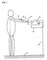
- FIG. 1 is a schematic view illustrating a basic concept of a data transmissionsystem in accordance with the present invention;
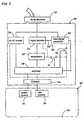
- FIG. 2 is a block diagram of a portable transceiver of the above systemadapted to be worn on the user's body;;
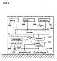
- FIG. 3 is a block diagram of an associated transceiver of the above systemadapted to be installed to an equipment utilizing the transmitted data;
- FIG. 4 is a perspective view of the portable transceiver;
- FIG. 5 is a perspective view of the portable transceiver incorporated in a wristwatch;
- FIG. 6 is a perspective view of the portable transceiver realized in the form of aring;
- FIG. 7 is schematic view of the system utilized for a keyless entry system for avehicle;
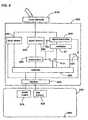
- FIG. 8 is a block diagram of a portable transceiver utilized in a datatransmission system In accordance with another embodiment of the presentinvention;
- FIG. 9 is a block diagram of an associated transceiver of the above system;and
- FIG. 10 is a schematic view of the system utilized in an automated gatesystem.
- Referring first to FIG. 1, there is shown a principle of a data transmissionsystem using a human body as a signal transmission path. The systemincludes a portable transceiver10 (hereinafter referred to as a first transceiver)adapted to be worn on the human body, and an associated transceiver30(hereinafter referred to as a second transceiver) adapted to be installed on an
equipment 50 which utilizes data transmitted from the first transceiver forcontrolled operation of the equipment. Thefirst transceiver 10 has asignal electrode 11 and aground electrode 12 which are held in contact with theuser's body. When the user wearing thefirst transceiver 10 touches atouchelectrode 31 of thesecond transceiver 30, a signal path is established whichextends from thesignal electrode 11 through a portion of the user's body, thetouch electrode 31, an internal circuit of thesecond transceiver 30, a circuitground of thesecond transceiver 30, a groundG, the other portion of theuser's body, theground electrode 12 and an internal circuit of thefirsttransceiver 10. The signal path extending through the human body isindicated by dotted lines. Thus, a voltage signal applied across theelectrodes second transceiver 30 when theuser touches thetouch electrode 31. In FIG. 1, the circuit ground of thesecond transceiver 30 is connected through aground line 54 to the ground Gfor the sake of simplicity. However, the circuit ground may be capacitivelyconnected to the ground G or even capacitively connected directly to the majorportion of the user's body for establishing the signal path. - As shown in FIG. 2, the
first transceiver 10 includes abattery 14 andvarious circuits energized by the battery. The circuits includes adata memory 15 storing data to be transmitted, acontroller 16, amodulator 17 modulatingthe data into a modulated voltage signal, asignal transmitter 18 applying themodulated voltage signal across thesignal electrode 11 and thegroundelectrode 12 which are spaced each other by about 5 to 10 mm. Alsoincluded in the circuits is astart signal detector 20 which is connected todetect a start signal transmitted from thesecond transceiver 30 through thesignal electrode 11. The start signal is received across thesignal electrode 11 and acircuit ground 19. Thecircuit ground 19 may be connected to theground electrode 12. Only thecontroller 16 and thestart signal detector 20are constantly energized by thebattery 14 to be ready for detecting the startsignal from thesecond transceiver 30. In the non-operative condition wherethefirst transceiver 10 is not transmitting the data, thecontroller 16 is kept in a sleep mode of consuming less electric current from thebattery 14. When thestart signal is received as a consequence of the user touching thetouchelectrode 31, thestart signal detector 20 wakes up thecontroller 16 which inturn energizes thedata memory 15, themodulator 17, and thesignaltransmitter 18 by thebattery 14 to apply the modulated voltage signal acrossthesignal electrode 11 and theground electrode 12 for initiating the datatransmission. Thecontroller 16 incorporates a timer which starts upondetection of the start signal to provide a predetermined time during which thedata is transmitted. After the elapse of the predetermined time, thecontroller 16 responds to deenergize themodulator 17, thesignal transmitter 18 and thedata memory 15. For this purpose, thecontroller 16 includes power switches21 and22 which are actuated by the output of thestart signal detector 20 andthe timer to selectively energize and deenergize themodulator 17, thesignaltransmitter 18 and thedata memory 15. Dotted lines in FIG. 2 show powersupply lines from the battery. Any other means for determining the end of thedata transmission may be utilized instead of the timer. Thus, aftertransmitting the data, thecontroller 16 goes back into the sleep mode ofconsuming less current or energy but being kept ready to detect of the startsignal for another data transmission. - The
signal transmitter 18 is designed to flow substantially constantcurrent between thesignal electrode 11 and theground electrode 12 whenapplying the modulated voltage signal thereacross irrespective of varyingelectrical resistance between the electrodes through a portion of the humanbody, thereby assuring reliable data transmission to thesecond transceiver 30.Further, thefirst transceiver 10 optionally includes adisplay 24 for visualindication of the data stored In thedata memory 15. - As shown inFIG. 3, the
second transceiver 30 includes various circuitsconnected to thetouch electrode 31 disposed outside or on the exterior of ahousing of the transceiver. The circuits are energized by apower source 51 provided in theequipment 50 to which thesecond transceiver 30 is attached.The circuits are commonly connected to acircuit ground 39 which is in turnconnected to aground terminal 59 of the equipment for connection with theground G. The circuits includes atouch sensor 32 which is connected to thetouch electrode 32 to give a touch signal when thetouch electrode 31 istouched by the user's body. Also included in the circuits are astart signalgenerator 33, asignal detector 34, ademodulator 35, and acontroller 36which controls the operations of the circuits. Thestart signal generator 33applies the start signal to thetouch electrode 31 in response to the touchsignal. The start signal generated is, for example, a uniform AC voltagesignal. Thesignal detector 34 detects the modulated voltage signal which istransmitted from the first transceiver and received across thetouch electrode 31 and thecircuit ground 39. The modulated voltage signal thus detected isdemodulated at thedemodulator 35 to derive the first data which is then fed tothe equipment to be processed thereat. - Under the non-operating condition where the touch electrode is nottouched by the human body, only the
controller 36 and thetouch sensor 32 areenergized to be ready for detection of the touching. Upon thetouch electrode 31 being touched, thetouch sensor 32 gives the touch signal to thecontroller 36 which responds to closeswitches start signalgenerator 33, thesignal detector 34, and thedemodulator 35, therebygenerating the start signal and making the circuits ready for receiving the datafrom the first transceiver. Thecontroller 36 also includes a timer which starts,upon receiving the touch signal, to provide a predetermined time intervalduring which the data transmission from thefirst transceiver 10 is expected tocomplete. After the elapse of the predetermined time interval, thecontroller 36 responds to open theswitches start signalgenerator 33, thesignal detector 34, and thedemodulator 35. Thus, thesecond transceiver 30 is kept in a sleep mode of consuming less electricity until thetouch electrode 31 is touched. Dotted lines in FIG. 3 show powersupply lines. Thesecond transceiver 30 further includes aninterface 44 fortransferring the data to the equipment as well as for receiving the powersupply therefrom. - As shown in FIG. 4, the circuits of the
first transceiver 10 are integratedinto asingle chip 60 which is mounted on adisk 61 together with thebutton-shapedbattery 14. Thesignal electrode 11 and theground electrode 12 are disposed on the back of thedisk 61. Thedisk 61 is incorporated into awrist watch as a back plate thereof, as shown in FIG. 5, so that theelectrodes chip 60 may be incorporated together with the button-shapedbattery 14 ina gem-like shell 64 which is supported on top of aring 65. Thesignalelectrode 11 and theground electrode 12 are disposed on the interior of thering4 to be always kept in contact with the finger of the user. Likewise, thecircuit of thesecond transceiver 30 may be integrated into a single chip so asto be readily incorporated or attached to the equipment. At least one of thesignal electrode 11, theground electrode 12, and thetouch electrode 31 maybe covered with a dielectric material to establish a capacitive coupling to thecorresponding portion of the user's body, avoiding the electrical double layersat the interface between the electrode and the user's body for reliable datatransmission. - It is noted that the circuits of the first and second transceivers are shownaccording to their functions in FIGS. 2 and 3 for easy understanding of theoperations of the transceivers. Therefore, the
modulator 17 and thedemodulator 35 may be realized by software schemes included in therespective controllers - The second transceiver may include a chassis of electrically conductivematerial to which the circuit ground is coupled. The chassis has a sufficientsurface area for establishing a strong capacitive coupling to the groundG for effective data transmission through the human body between the first andsecond transceivers. Altemately, the circuit ground of the second transceivermay be directly connected to the ground G by means of a conductive wire orline. Further, in order to enhance the electrostatic coupling between thehuman body and the circuit ground of the second transceiver, it may beeffective to use an electrically conductive sheet which is adapted to beinstalled on a site such that the human body wearing the first transceiverstands on the conductive sheet
- FIG. 7 shows one typical application of the present system for a keylessentry system of a vehicle. The
first transceiver 10 in the form of the wristwatch is carried by the user, while the twosecond transceivers 30 areembedded in adoor 80 of the vehicle to be connected commonly to adoorlock mechanism 85. Onetransceiver 30 is utilized as a door opening sensorwith thetouch electrode 31 forming adoor handle 81, while theothertransceiver 30 is utilized as a door locking sensor with thetouch electrode 31forming adoor lock 82. The circuit grounds of the twotransceivers 30 arecommonly connected to a body of the vehicle. When the user wearing thefirst transceiver 10 touches thedoor handle 81, the data stored in the datamemory of thefirst transceiver 10 is transmitted to thesecond transceiver 30in a manner as described hereinbefore. The data, which is an identificationdata for the vehicle, is compared with a reference data stored in the door lockmechanism. When the received data is judged to coincide with the referencedata, thedoor lock mechanism 85 operates to unlock the door. When theuser touches thedoor lock 82 on the other hand, theassoclated transceiver 30gives the received data to themechanism 85 which responds to identify thereceived data and operate to lock the door when the received data is coincidewith the reference data. Alternately, the second transceiver may bespecifically designed such that thecontroller 36 stores the reference data andhas a function of comparing the received data with the reference data so as to give a unlock signal and a lock signal for actuating themechanism 85 tounlock and lock the door. - Likewise, the present system can be also adapted to an ignition systemfor starting the vehicle's engine. For instance, the second transceiver can beembedded in a suitable area around a vehicle's dashboard with the touchelectrode exposed at an easily accessible position. Thus, the user wearingthe first transceiver can be easy to start the engine simply by touching thetouch electrode.
- Referring to FIGS. 8 and 9, there is shown a data transmission system inaccordance with a second embodiment of the present invention which isdesigned to effect a bilateral data transmission between a
first transceiver 10Aand asecond transceiver 30A. These transceivers are identical to those ofthe first embodiment except that thefirst transceiver 10A further includes ademodulator 25 for demodulating data transmitted from thesecond transceiver 30A and that thesecond transceiver 30A further includes amodulator 37 formodulating the data to be transmitted from thesecond transceiver 30A. Likecircuit components are designated by like reference numerals with a suffixletter of "A". Themodulator 37 of thesecond transceiver 30A gives amodulated voltage signal indicative of the data to be transmitted to thefirsttransceiver 10A. Thesignal transmitter 33A of thesecond transceiver 30A isresponsible for applying the modulated voltage signal to thetouch electrode 31A for data transmission to the first transceiver. The voltage signal also actsas the start signal for starting the data transmission from thefirst transceiver 10A to thesecond transceiver 30A. In this sense, thesignal transmitter 33Aserves as thestart signal generator 33 of the first embodiment in thisconnection, thesignal detector 20A of thefirst transceiver 10A detects themodulated voltage signal transmitted from thesecond transceiver 30A andtherefore serves as thestart signal detector 20 of the first embodiment. - In operation, when the user wearing the
first transceiver 10A touches thetouch electrode 31A of the second transceiver, thetouch sensor 32A providesa touch signal in response to which thecontroller 36A energizes themodulator 37, thesignal transmitter 33A, thedemodulator 35A, and thesignal detector 34A. At first, thecontroller 36A retrieves the data from adata memory 52A oftheequipment 50 and instructs to give and apply the modulated voltage signalindicative of the data. In response to the voltage signal from thesecondtransceiver 30A, thecontroller 16A of thefirst transceiver 10A activates thedata memory 15A and performs a suitable processing of the data from thedata memory 15A in consideration of the data received from thesecondtransceiver 30A. Thecontroller 16A updates the data of thedata memory 15A depending upon the result of the processing. Thereafter, thecontroller 16A activates themodulator 17A and thesignal transmitter 18A so as totransmit the modulated voltage signal indicative of the updated data to thesecond transceiver 30A through theelectrodes second transceiver 30A is converted into thedata which is utilized by thecontroller 36A for a controlled operation of anequipment or passed to the equipment to be processed thereat for a specificoperation of the equipment. In this manner, the two-way data transmission ismade between the first and second transceivers in a half-duplex manner.Depending upon a specific application to which the system is applied, thesystem may be designed to have more than one data transmission cycles inwhich the one-way data transmission from either of the first and the secondtransceiver repeats twice or more. In such case, the data in thedata memory 15A of thefirst transceiver 10A is modified or updated by the data transmittedfrom thesecond transceiver 30A. - Also in this embodiment, the
first transceiver 10A as well as thesecondtransceiver 30A are designed to be of less energy consumption type. That is,thefirst transceiver 10A is kept in the sleep mode of energizing only thecontroller 16A and thesignal detector 20A until the modulated voltage signal is received from thesecond transceiver 30A, and comes back again in the sleepmode after the data transmission between the first and second transceiversare completed. In other words, thedata memory 15A, themodulator 17A, thesignal transmitter 18A, and thedemodulator 25 are energized by closure of theswitches second transceiver 30A. It iswithin the predetermined time period that the data transmission between thefirst and second transceivers is completed. Likewise, thesecond transceiver 30A is kept in the sleep mode of energizing only thecontroller 36A and thetouch sensor 32A until thetouch electrode 31A is touched by the human body,and come back to the sleep mode after the data transmission between the firstand second transceivers are completed. Thus, thesignal transmitter 33A, themodulator 37, thesignal detector 34A, and thedemodulator 35A areenergized by closure ofswitches - FIG. 10 shows a specific application of the data transmission system ofthe second embodiment to an automated gate installed on a railway station orthe like which charges the person utilizing an associated facility. When thesystem is applied to the automated gate of the rail way station, the data in the
first transceiver 10A includes information as contained a conventional ticket orpass. Thesecond transceiver 30A is embedded in agate 90 and isconnected to a power source in the gate. The circuit ground of the secondtransceiver is connected to an electricallyconductive sheet 94 on which theperson stands for enhancing the capacitive coupling between the human body and the circuit ground. Alternately, the circuit ground may be simplyconnected to the ground. As soon as the person wearing thefirst transceiver 10A touches thetouch electrode 31A exposed on top of thegate 90, the datatransmission starts between the first and second transceivers and the datareceived at the second transceiver is processed to see whether the dataIndicates information which permits the person to pass through the gate.Such data processing is made in the controller of the second transceiver or agate controller 91 equipped In thegate 90 to receive the data from the secondtransceiver. If the data shows that the person is permitted to pass through,thegate controller 91 Is activated to open adoor 92. In the like manner as ina conventional automated ticket gate, the data on either one of the first andsecond transceivers can be modified by the data in view of the data on theother transceiver. Thus, the present system enables a ticket-less gatesystem which is free from using the conventional ticket or pass and istherefore convenient for the user. - In this connection, the data of the
first transceiver 10A can be renewed atan expense of corresponding fee with the use of thesecond transceiver 30Aas a ticket machine. That is, the data of thefirst transceiver 10A can bewritten by data transfer from thesecond transceiver 30A. Alternately, thedata memory of thefirst transceiver 10A can be made detachable so that thedata can be renewed with the use of a separate data writer. The data in thedata memory is indicated at the display for confirmation by the user. - Further, the present system can be well adapted for a cashlesstransaction though electronic money. In this application, the
first transceiver 10A is adapted to store the electronic money in the data memory, while thesecond transceiver is Installed at a register in a shop or POS (point of sale)terminal. When the user wearing the first transceiver touches the touchelectrode of the POS terminal, for example, at the reception of a product orservice, the data indicating the charge of the product or the service is transmitted to the data memory of the first transceiver. Subsequently, thedata or the electronic money for settlement of the charge is transmitted fromthe first transceiver to the second transceiver to update the data processed atthe POS terminal. At the same time, the electronic money in the firsttransceiver is subtracted by the charge to update the electronic money whichis indicated at the display for confirmation by the user. The electronic moneyof the first transceiver can be written at a bank or financial institution by thedata transmission from the second transceiver installed as a money generatingdevice in exchange of a cash or deposited money. Further, the data memorymay be detachable to the first transceiver so as to placed singly in a dedicatedmoney generating device for rewriting the electronic money. The electronicmoney stored in the first transceiver can be checked at the display of the firsttransceiver. - Further, the present system can be well adapted for a pay phone systemin which the second transceiver is installed in a pay phone with the touchelectrode exposed on a handset. Thus, when the user wearing the firsttransceiver grasps the handset, the data transmission between the first andsecond transceiver can be made for payment of the telephone charges.
- 10
- first transceiver
- 11
- signal electrode
- 12
- ground electrode
- 14
- battery
- 15
- data memory
- 16
- controller
- 17
- modulator
- 18
- signal transmitter
- 19
- circuit ground
- 20
- start signal detector
- 21
- switch
- 22
- switch
- 24
- display
- 25
- demodulator
- 30
- second transceiver
- 31
- touch electrode
- 32
- touch sensor
- 33
- start signal generator
- 34
- signal detector
- 35
- demodulator
- 36
- controller
- 37
- modulator
- 41
- switch
- 42
- switch
- 44
- interface
- 50
- equipment
- 54
- ground line
- 59
- ground terminal
- 60
- chip
- 61
- dis
Claims (14)
- A data transmission system using a human body as a signal transmission path,said system comprising a first transceiver (10) adapted to be worn on a humanbody, and a second transceiver (30) adapted to be connected to an associated devicewhich utilizes data transmitted from said first transceiver,
said first transceiver (10) comprising:said second transceiver (30) comprising:a battery (14);a ground electrode (12) for direct contact with the human body to establish anelectrical connection through the human body to a ground;a signal electrode (11) spaced from said ground electrode;a data memory (15) for storing first data to be transmitted;a first modulator (17) which is energized selectively by said battery for convertingsaid first data into a first modulated voltage signal;a first signal transmitter (18) which is energized selectively by said battery toapply the first modulated voltage signal across said signal electrode andsaid ground electrode;a start signal detector (20) which is constantly energized by said battery fordetecting a start signal; anda first controller (16) which is constantly energized by said battery and is connectedto said start signal detector so as to energize said first modulator andsaid first signal transmitter for applying said first modulated voltage signal inresponse to said start signal, andcharacterized in thata second circuit ground (39) adapted to be connected to the ground;a single touch electrode (31) for direct contact with a portion of the humanbody wearing said first transceiver,a second signal detector (34) connected across said touch electrode and saidsecond circuit ground to detect said first modulated voltage signal;a second demodulator (35) for converting said first modulated voltage signalback into said first data;a start signal generator (33) for generating said start signal;a touch sensor (32) which is connected to said touch electrode to give a touchsignal when said touch electrode is touched by the human body;a second controller (36) which energizes said start signal generator to providesaid start signal only in response to said touch signal, thereby enabling datatransmission from said first transceiver to said second transceiver,
said start signal generator provides said start signal through said touchelectrode (31),
said signal electrode (11) is arranged for direct contact with the humanbody and for receiving said start signal, and said first signal transmitter (10) includesa current regulator which keeps a current flowing between said signalelectrode (11) and said ground electrode (12) substantially at a fixed level. - The data transmission system as set forth in claim 1, whereinsaid first controller (16) has a function of deenergizing said first modulator (17) andsaid signal transmitter (18) after transmitting said data.
- The data transmission system as set forth in claim 1, whereinsaid second transceiver (30A) further includes:a second modulator (37) for converting second data into a second modulatedvoltage signal which is applied between said touch electrode (31A) and said secondcircuit ground (39A);said first transceiver (10A) further including:a first demodulator (25) for converting said second modulated signal, which isdetected through said signal electrode (11A), into said second data, andsaid first controller (10A) having a function of modifying said first data in accordancewith said second data.
- The data transmission system as set forth in claim 1, whereinat least one of said signal electrode (11), said ground electrode (12) , and saidtouch electrode (31) is covered with an insulation layer.
- The data transmission system as set forth in claim 1, wherein
said second circuit ground (39) is connected to a ground line which is directly connectedto the ground. - The data transmission system as set forth in claim 1, wherein
said second transceiver (30) has an electrically conductive chassis to which saidsecond circuit ground is connected. - The data transmission system as set forth in claim 1, wherein
said second circuit ground (39A) is connected to an electrically conductive sheet(49) which is adapted to be installed on a site such that the human body wearingsaid first transceiver stands on said conductive sheet. - The data transmission system as set forth in claim 1, wherein
said first transceiver (10) includes a display (24) for indication of said first data. - The data transmission system as set forth in claim 1, wherein
said data memory (15) is detachably mounted to said first transceiver (10). - The data transmission system as set forth in claim 1, wherein
said first transceiver (10) is held on a disk (61) with said signal electrode (11) and
said ground electrode (12) being arranged on one face of said disk. - The data transmission system as set forth in claim 1, wherein
said first transceiver (10) is held on a ring (65) with said signal electrode (11) and
said ground electrode (12) being arranged on an interior face of said ring. - The data transmission system as set forth in claim 1, wherein
said second transceiver (30) has a power source which energizes said touch sensor(32) and said second controller (36) constantly by said power source, whileenergizing said second signal detector (34) and said second demodulator (35) selectivelyby said power source, said second controller (36) responsive to saidtouch signal to energize said second signal detector (34) and said second demodulator(35). - The data transmission system as set forth in claim 12, wherein
said second controller (36) has a function of deenergizing said second signal detector(34) and said second demodulator (35) after deriving said first data. - The data transmission system as set forth in claim 12, wherein
said second controller (36) has a function of providing a predetermined time periodfor receiving said first demodulated voltage signal and deenergizing said secondsignal detector (34) and said second demodulator (35) after the elapse of saidpredetermined time period.
Priority Applications (4)
| Application Number | Priority Date | Filing Date | Title |
|---|---|---|---|
| DE60004980TDE60004980T2 (en) | 2000-06-27 | 2000-06-27 | Data transmission system using a human body as a signal transmission path |
| EP00113564AEP1168678B1 (en) | 2000-06-27 | 2000-06-27 | Data transmission system using a human body as a signal transmission path |
| TW089112706ATW517213B (en) | 2000-06-27 | 2000-06-28 | Data transmission system using human body as the signal transmission path |
| US09/605,357US6771161B1 (en) | 2000-06-27 | 2000-06-29 | Data transmission system using a human body as a signal transmission path |
Applications Claiming Priority (2)
| Application Number | Priority Date | Filing Date | Title |
|---|---|---|---|
| EP00113564AEP1168678B1 (en) | 2000-06-27 | 2000-06-27 | Data transmission system using a human body as a signal transmission path |
| US09/605,357US6771161B1 (en) | 2000-06-27 | 2000-06-29 | Data transmission system using a human body as a signal transmission path |
Publications (2)
| Publication Number | Publication Date |
|---|---|
| EP1168678A1 EP1168678A1 (en) | 2002-01-02 |
| EP1168678B1true EP1168678B1 (en) | 2003-09-03 |
Family
ID=33300882
Family Applications (1)
| Application Number | Title | Priority Date | Filing Date |
|---|---|---|---|
| EP00113564AExpired - LifetimeEP1168678B1 (en) | 2000-06-27 | 2000-06-27 | Data transmission system using a human body as a signal transmission path |
Country Status (4)
| Country | Link |
|---|---|
| US (1) | US6771161B1 (en) |
| EP (1) | EP1168678B1 (en) |
| DE (1) | DE60004980T2 (en) |
| TW (1) | TW517213B (en) |
Cited By (2)
| Publication number | Priority date | Publication date | Assignee | Title |
|---|---|---|---|---|
| US8704651B2 (en) | 2007-02-01 | 2014-04-22 | Hella Kgaa Hueck & Co. | Method for attributing equipment operation to a specific operator |
| CN104809774A (en)* | 2014-01-28 | 2015-07-29 | 华创车电技术中心股份有限公司 | Vehicle starting management method |
Families Citing this family (78)
| Publication number | Priority date | Publication date | Assignee | Title |
|---|---|---|---|---|
| DE10132031A1 (en)* | 2001-07-03 | 2003-01-23 | Texas Instruments Deutschland | Process for enabling authenticated access of an individual to a protected area and security system for carrying out the process |
| US7352996B2 (en)* | 2002-03-29 | 2008-04-01 | Ncr Corporation | System and method for coupling users to a retail computer system with low risk of eavesdropping |
| EP1530526B1 (en)* | 2002-08-15 | 2008-10-15 | Ident Technology AG | Circuit for selectively producing switching signals |
| US7009488B2 (en)* | 2002-09-25 | 2006-03-07 | Hrl Laboratories, Llc | Selective equipment lockout |
| US7412229B2 (en) | 2002-10-02 | 2008-08-12 | Nippon Telephone And Telegraph Corporation | Sales apparatus and method of transmitting and receiving merchandise information by electric field induced in human body |
| KR100873683B1 (en)* | 2003-01-25 | 2008-12-12 | 한국과학기술연구원 | Human Body Communication Method, Human Body Communication System and Capsule Endoscope |
| US8155586B2 (en)* | 2003-01-25 | 2012-04-10 | Korea Institute Of Science And Technology | Method and system for data communication using a body |
| US7312788B2 (en)* | 2003-03-11 | 2007-12-25 | Fraunhofer-Gesellschaft Zur Foerderung Der Angewandten Forschung E.V. | Gesture-based input device for a user interface of a computer |
| JP2005034520A (en)* | 2003-07-18 | 2005-02-10 | Tokai Rika Co Ltd | Physical condition monitoring system |
| FR2869859B1 (en)* | 2004-05-04 | 2007-08-17 | Valeo Securite Habitacle Sas | SYSTEM FOR HANDS-FREE ACCESS AND FUNCTION CONTROL OF A MOTOR VEHICLE |
| FR2872468B1 (en)* | 2004-06-30 | 2007-10-19 | Valeo Securite Habitacle Sas | DEVICE FOR ACCESSING A VEHICLE USING A CIRCULATING CURRENT THROUGH THE BODY |
| DE102004037587A1 (en)* | 2004-08-03 | 2006-02-23 | Enocean Gmbh | Energy self-sufficient electronic system |
| EP1798876A4 (en)* | 2004-10-05 | 2010-04-14 | Takaharu Sekine | Working condition detection device |
| DE102004050071A1 (en)* | 2004-10-13 | 2006-04-27 | Daimlerchrysler Ag | Mobile identification sensor detecting device for vehicle, has two inner identification receivers arranged in neck rest of vehicle front seats, where signal coupling is formed between sensor and receivers as capacitive coupling |
| EP1815442A1 (en)* | 2004-11-16 | 2007-08-08 | Koninklijke Philips Electronics N.V. | Identification system and method of operating same |
| WO2006056424A2 (en)* | 2004-11-23 | 2006-06-01 | Ident Technology Ag | Closing arrangement |
| EP1821432B1 (en)* | 2004-12-08 | 2011-07-06 | Seiko Instruments Inc. | Information transmission through-human-body system and transmitter/receiver |
| DE102005003488B4 (en)* | 2005-01-25 | 2009-03-19 | Sick Ag | Capacitive sensor and monitoring method |
| KR100842250B1 (en)* | 2005-12-08 | 2008-06-30 | 한국전자통신연구원 | Apparatus for communications sensing human touch and method thereof |
| KR100772525B1 (en)* | 2005-12-08 | 2007-11-01 | 한국전자통신연구원 | apparatus and method for providing service based on touch and play, and the system using the same |
| KR100725228B1 (en)* | 2005-12-16 | 2007-06-04 | 한국과학기술원 | Data communication device and module using human body |
| JP4539551B2 (en)* | 2005-12-20 | 2010-09-08 | ソニー株式会社 | Information processing system and method, information processing apparatus and method, and program |
| KR100723638B1 (en)* | 2006-01-12 | 2007-06-04 | 한국과학기술원 | Wireless Audio Transceiver Using Human Body |
| DE102006008144A1 (en)* | 2006-02-20 | 2007-08-23 | Huf Hülsbeck & Fürst Gmbh & Co. Kg | Handle for e.g. boot door of motor vehicle, has electronic unit with communication area that is operated in two conditions, where area acts as transmitting unit in one condition to transmit waking signal to person and transmitter |
| DE102006048372A1 (en)* | 2006-02-20 | 2007-09-20 | Huf Hülsbeck & Fürst Gmbh & Co. Kg | switching device |
| US20070200824A1 (en)* | 2006-02-24 | 2007-08-30 | Choo Eugene K | Wireless foldable mouse |
| AT503301B1 (en) | 2006-05-04 | 2007-09-15 | Evva Werke | Access control device, has lock with blocking element, actuation element, electronic key, electric circuit with receiving unit for reception of identification data from key, and evaluation circuit for determining access authorization |
| US8594568B2 (en)* | 2006-05-08 | 2013-11-26 | Koninklijke Philips N.V. | Method of transferring application data from a first device to a second device, and a data transfer system |
| KR100799571B1 (en)* | 2006-06-20 | 2008-01-30 | 한국전자통신연구원 | Communication device using human body and method |
| AT503122B1 (en)* | 2006-07-25 | 2007-08-15 | Evva Werke | Access control device for use in radio-remote controlled locks, particularly for closing and releasing car doors, has reception unit in form of device which is separate from lock, and comprises capacitive coupling face |
| JP2008050892A (en) | 2006-08-28 | 2008-03-06 | Alps Electric Co Ltd | Keyless entry device |
| EP2127161A2 (en)* | 2007-02-14 | 2009-12-02 | Kaba AG | System and portable device for transmitting identification signals |
| US8643469B2 (en)* | 2007-03-05 | 2014-02-04 | Kaba Ag | Access control system, and closing mechanism |
| EP2191458A4 (en) | 2007-08-19 | 2012-02-15 | Ringbow Ltd | Finger-worn devices and related methods of use |
| US8535223B2 (en) | 2008-02-28 | 2013-09-17 | Koninklijke Philips N.V. | Wireless patient monitoring using streaming of medical data with body-coupled communication |
| DE102008013476A1 (en)* | 2008-03-10 | 2009-09-17 | Volkswagen Ag | Method and device for generating a user recognition signal |
| TWI368188B (en)* | 2008-03-18 | 2012-07-11 | Univ Nat Taiwan | Intra-body biomedical communication system (ibc) and the method use of |
| JP2010003012A (en)* | 2008-06-18 | 2010-01-07 | Denso Corp | Guidance system |
| US8668145B2 (en) | 2009-04-21 | 2014-03-11 | Technology Innovators Inc. | Automatic touch identification system and method thereof |
| US8297499B2 (en)* | 2009-04-21 | 2012-10-30 | Technology Innovators Inc. | Automatic touch identification system and method thereof |
| US9703398B2 (en)* | 2009-06-16 | 2017-07-11 | Microsoft Technology Licensing, Llc | Pointing device using proximity sensing |
| US20100321159A1 (en)* | 2009-06-18 | 2010-12-23 | Authentec, Inc. | Touch based data communication using biometric finger sensor and associated methods |
| JP5271183B2 (en)* | 2009-07-22 | 2013-08-21 | アルプス電気株式会社 | Communication apparatus and communication method |
| CN103945131B (en)* | 2010-02-19 | 2018-05-01 | 株式会社尼康 | The image acquisition method of electronic equipment and electronic equipment |
| JP2011259172A (en)* | 2010-06-08 | 2011-12-22 | Sony Corp | Communication device, communication system, mode changeover method and program |
| KR101261687B1 (en)* | 2010-08-09 | 2013-05-06 | 주식회사 팬택 | Broadcasting System and Method for using human body communication |
| US8457692B2 (en)* | 2010-10-07 | 2013-06-04 | Research In Motion Limited | Method and system for preventing device operation when driving |
| JP2012113383A (en)* | 2010-11-22 | 2012-06-14 | Toshiba Corp | Human body communication device and authentication method therefor |
| WO2013056071A1 (en) | 2011-10-14 | 2013-04-18 | Beam Technologies, Llc | Oral health care implement and system with oximetry sensor |
| AT512076A1 (en)* | 2011-10-18 | 2013-05-15 | Evva Sicherheitstechnologie | METHOD OF ACCESS CONTROL |
| US20130176100A1 (en)* | 2012-01-08 | 2013-07-11 | Tk Holdings Inc. | Automated electronic device network pairing based on electric field coupling |
| US20150329080A1 (en)* | 2012-10-18 | 2015-11-19 | Johnson Controls Automotive Electronics Sas | Control transmitter for a motor vehicle and in particular for a device for closing a motor vehicle, and control system particularly for a motor vehicle |
| AT513659B1 (en) | 2012-11-14 | 2015-11-15 | Evva Sicherheitstechnologie | Method for transmitting data between a first transmitting and / or receiving device and a second transmitting and / or receiving device |
| AT513658B9 (en) | 2012-11-14 | 2016-02-15 | Evva Sicherheitstechnologie | Method for transmitting data between a first transmitting and / or receiving device and a second transmitting and / or receiving device |
| AT513656A1 (en) | 2012-11-14 | 2014-06-15 | Evva Sicherheitstechnologie | Data transfer device |
| EP2929445B1 (en) | 2012-12-07 | 2020-02-05 | Joyson Safety Systems Acquisition LLC | System for automated network pairing using electric field coupling |
| AT513934A3 (en) | 2013-02-05 | 2021-04-15 | Evva Sicherheitstechnologie | Method and device for access control |
| US20140235216A1 (en)* | 2013-02-18 | 2014-08-21 | Microchip Technology Incorporated | Using bodycom to modify the configuration of a device based upon context |
| US20140310900A1 (en)* | 2013-03-05 | 2014-10-23 | Beam Technologies, Llc | Toothbrush and System with Sensors and User Identification |
| US20140283021A1 (en)* | 2013-03-14 | 2014-09-18 | Beam Technologies, Llc | User Identification System for Parental and Security Controls |
| US9564032B2 (en)* | 2013-05-31 | 2017-02-07 | Motorola Solutions, Inc | Enhanced security system |
| US9117340B2 (en)* | 2013-06-04 | 2015-08-25 | Igt | Player tracking through touch surface signal conduits |
| US20150044969A1 (en)* | 2013-08-09 | 2015-02-12 | Microchip Technology Incorporated | Wireless Transmission System and Method |
| US9916707B2 (en) | 2013-08-19 | 2018-03-13 | Arm Ip Limited | Interacting with embedded devices within a user's environment |
| KR101869624B1 (en) | 2013-11-22 | 2018-06-21 | 선전 구딕스 테크놀로지 컴퍼니, 리미티드 | Secure human fingerprint sensor |
| WO2015081326A1 (en)* | 2013-11-27 | 2015-06-04 | Shenzhen Huiding Technology Co., Ltd. | Wearable communication devices for secured transaction and communication |
| WO2015134458A1 (en) | 2014-03-04 | 2015-09-11 | Tk Holdings Inc. | System and method for controlling a human machine interface (hmi) device |
| US9606682B2 (en)* | 2014-04-21 | 2017-03-28 | Avago Technologies General Ip (Singapore) Pte. Ltd. | Wearable device for generating capacitive input |
| EP3140928B1 (en)* | 2014-05-09 | 2019-06-26 | Sony Corporation | Wearable wireless electronic devices and methods of providing communications via wearable wireless electronic devices |
| US9396378B2 (en)* | 2014-06-12 | 2016-07-19 | Yahoo! | User identification on a per touch basis on touch sensitive devices |
| US9354011B2 (en) | 2014-06-25 | 2016-05-31 | Anfcs, Llc | Magazine based, firearm safety apparatus for modifying existing firearms employing a digital, close proximity communications system and a low power electro-permanent magnet interlock system |
| KR20160129874A (en) | 2014-07-07 | 2016-11-09 | 선전 후이딩 테크놀로지 컴퍼니 리미티드 | Integration of touch screen and fingerprint sensor assembly |
| US9606662B2 (en) | 2015-06-10 | 2017-03-28 | International Business Machines Corporation | Touch interface with person recognition |
| CN104983143B (en)* | 2015-07-31 | 2017-03-01 | 福州臻美网络科技有限公司 | a smart bracelet |
| DE102016203521A1 (en) | 2016-03-03 | 2017-09-07 | Volkswagen Aktiengesellschaft | Method and system for authenticating a user and a motor vehicle |
| US11642026B2 (en)* | 2019-02-20 | 2023-05-09 | Electronics And Telecommunications Research Institute | Human body sensing device |
| US11233583B2 (en)* | 2019-10-28 | 2022-01-25 | Electronics And Telecommunications Research Institute | Human body communication device having single electrode |
| GEP20207171B (en)* | 2020-02-14 | 2020-10-26 | Davit Tofchishvili | Method for trade and system for implementation thereof |
Family Cites Families (14)
| Publication number | Priority date | Publication date | Assignee | Title |
|---|---|---|---|---|
| EP0109184A3 (en)* | 1982-10-12 | 1985-07-24 | Roundel Electronics Limited | Identification system |
| JPS60119873A (en)* | 1983-11-29 | 1985-06-27 | 日産自動車株式会社 | Locking controller for vehicle |
| JPS6146639A (en)* | 1984-08-11 | 1986-03-06 | Matsushita Electric Works Ltd | Information transmitter |
| US5471212A (en)* | 1994-04-26 | 1995-11-28 | Texas Instruments Incorporated | Multi-stage transponder wake-up, method and structure |
| EP0824799B1 (en) | 1995-05-08 | 2002-08-21 | Massachusetts Institute Of Technology | System for non-contact sensing and signalling using human body as signal transmission medium |
| DE19547560C2 (en)* | 1995-12-20 | 2000-01-13 | Daimler Chrysler Ag | Device for body-bound data transmission between two end devices |
| US5682032A (en)* | 1996-02-22 | 1997-10-28 | Philipp; Harald | Capacitively coupled identity verification and escort memory apparatus |
| US5796827A (en)* | 1996-11-14 | 1998-08-18 | International Business Machines Corporation | System and method for near-field human-body coupling for encrypted communication with identification cards |
| JP3425347B2 (en) | 1996-12-12 | 2003-07-14 | 日本電信電話株式会社 | Information transmission device via human body |
| US6346886B1 (en)* | 1996-12-20 | 2002-02-12 | Carlos De La Huerga | Electronic identification apparatus |
| JPH10266651A (en)* | 1997-03-25 | 1998-10-06 | Yazaki Corp | Key entry system |
| US6211799B1 (en)* | 1997-11-06 | 2001-04-03 | Massachusetts Institute Of Technology | Method and apparatus for transbody transmission of power and information |
| US6580356B1 (en)* | 1998-11-05 | 2003-06-17 | Eckhard Alt | Advanced personal identification systems and techniques |
| US6034617A (en)* | 1998-12-04 | 2000-03-07 | Eaton Corporation | Operator intent based passive keyless vehicle control system |
- 2000
- 2000-06-27EPEP00113564Apatent/EP1168678B1/ennot_activeExpired - Lifetime
- 2000-06-27DEDE60004980Tpatent/DE60004980T2/ennot_activeExpired - Lifetime
- 2000-06-28TWTW089112706Apatent/TW517213B/ennot_activeIP Right Cessation
- 2000-06-29USUS09/605,357patent/US6771161B1/ennot_activeExpired - Fee Related
Cited By (2)
| Publication number | Priority date | Publication date | Assignee | Title |
|---|---|---|---|---|
| US8704651B2 (en) | 2007-02-01 | 2014-04-22 | Hella Kgaa Hueck & Co. | Method for attributing equipment operation to a specific operator |
| CN104809774A (en)* | 2014-01-28 | 2015-07-29 | 华创车电技术中心股份有限公司 | Vehicle starting management method |
Also Published As
| Publication number | Publication date |
|---|---|
| DE60004980T2 (en) | 2004-07-22 |
| EP1168678A1 (en) | 2002-01-02 |
| DE60004980D1 (en) | 2003-10-09 |
| US6771161B1 (en) | 2004-08-03 |
| TW517213B (en) | 2003-01-11 |
Similar Documents
| Publication | Publication Date | Title |
|---|---|---|
| EP1168678B1 (en) | Data transmission system using a human body as a signal transmission path | |
| JP3319462B2 (en) | Data transmission system using human body as signal transmission path | |
| US20180082488A1 (en) | Parking meter and a device therefor | |
| US7543755B2 (en) | Electronic key, electronic locking apparatus, electronic security system, and key administering server | |
| US7742995B2 (en) | Pre-authenticated identification token | |
| EP3625729B1 (en) | Biometric enrolment | |
| US20250165951A1 (en) | Systems and methods for performing transactions | |
| US5682032A (en) | Capacitively coupled identity verification and escort memory apparatus | |
| US6489883B1 (en) | Non-contact data carrier system | |
| US8730012B2 (en) | Enabling identification token for a timed period | |
| US8474710B2 (en) | Access control proximity card with actuation sensor | |
| KR101756238B1 (en) | Smart card and control method thereof and nfc terminal and control method thereof | |
| JP4103589B2 (en) | Electronic key, electronic key system, key management server | |
| JP2003188833A (en) | Mobile data communication apparatus and two-way communication system | |
| JP3838901B2 (en) | Contact / contactless IC card | |
| JP2003132031A (en) | Data communication device | |
| JP2000036065A (en) | Non-contact type automatic ticket examination machine | |
| KR200209515Y1 (en) | Mobile phone battery pack equipped with opticpay transmitter | |
| KR20020019350A (en) | Method for data accurate of card reader using wireless type telecommunication unit | |
| JPH03197197A (en) | Bracelet-shaped non-contact recording medium | |
| JPH06266918A (en) | Non-contact gate system |
Legal Events
| Date | Code | Title | Description |
|---|---|---|---|
| PUAI | Public reference made under article 153(3) epc to a published international application that has entered the european phase | Free format text:ORIGINAL CODE: 0009012 | |
| AK | Designated contracting states | Kind code of ref document:A1 Designated state(s):AT BE CH CY DE DK ES FI FR GB GR IE IT LI LU MC NL PT SE Kind code of ref document:A1 Designated state(s):DE FR GB | |
| AX | Request for extension of the european patent | Free format text:AL;LT;LV;MK;RO;SI | |
| 17P | Request for examination filed | Effective date:20020117 | |
| 17Q | First examination report despatched | Effective date:20020424 | |
| AKX | Designation fees paid | Free format text:DE FR GB | |
| GRAH | Despatch of communication of intention to grant a patent | Free format text:ORIGINAL CODE: EPIDOS IGRA | |
| RBV | Designated contracting states (corrected) | Designated state(s):DE FR GB | |
| GRAS | Grant fee paid | Free format text:ORIGINAL CODE: EPIDOSNIGR3 | |
| GRAA | (expected) grant | Free format text:ORIGINAL CODE: 0009210 | |
| AK | Designated contracting states | Kind code of ref document:B1 Designated state(s):DE FR GB | |
| REG | Reference to a national code | Ref country code:GB Ref legal event code:FG4D | |
| REF | Corresponds to: | Ref document number:60004980 Country of ref document:DE Date of ref document:20031009 Kind code of ref document:P | |
| REG | Reference to a national code | Ref country code:IE Ref legal event code:FG4D | |
| ET | Fr: translation filed | ||
| PLBE | No opposition filed within time limit | Free format text:ORIGINAL CODE: 0009261 | |
| STAA | Information on the status of an ep patent application or granted ep patent | Free format text:STATUS: NO OPPOSITION FILED WITHIN TIME LIMIT | |
| 26N | No opposition filed | Effective date:20040604 | |
| REG | Reference to a national code | Ref country code:IE Ref legal event code:MM4A | |
| PGFP | Annual fee paid to national office [announced via postgrant information from national office to epo] | Ref country code:DE Payment date:20120620 Year of fee payment:13 | |
| PGFP | Annual fee paid to national office [announced via postgrant information from national office to epo] | Ref country code:FR Payment date:20120619 Year of fee payment:13 Ref country code:GB Payment date:20120627 Year of fee payment:13 | |
| REG | Reference to a national code | Ref country code:DE Ref legal event code:R119 Ref document number:60004980 Country of ref document:DE | |
| GBPC | Gb: european patent ceased through non-payment of renewal fee | Effective date:20130627 | |
| REG | Reference to a national code | Ref country code:FR Ref legal event code:ST Effective date:20140228 | |
| PG25 | Lapsed in a contracting state [announced via postgrant information from national office to epo] | Ref country code:DE Free format text:LAPSE BECAUSE OF NON-PAYMENT OF DUE FEES Effective date:20140101 Ref country code:GB Free format text:LAPSE BECAUSE OF NON-PAYMENT OF DUE FEES Effective date:20130627 | |
| PG25 | Lapsed in a contracting state [announced via postgrant information from national office to epo] | Ref country code:FR Free format text:LAPSE BECAUSE OF NON-PAYMENT OF DUE FEES Effective date:20130701 | |
| REG | Reference to a national code | Ref country code:DE Ref legal event code:R079 Ref document number:60004980 Country of ref document:DE Free format text:PREVIOUS MAIN CLASS: H04B0010130000 Ipc:H04B0010258100 | |
| REG | Reference to a national code | Ref country code:DE Ref legal event code:R119 Ref document number:60004980 Country of ref document:DE Effective date:20140101 Ref country code:DE Ref legal event code:R079 Ref document number:60004980 Country of ref document:DE Free format text:PREVIOUS MAIN CLASS: H04B0010130000 Ipc:H04B0010258100 Effective date:20140610 |