EP1168025A2 - Cable having side-emitting fiber under transparent or translucent cable jacket - Google Patents
Cable having side-emitting fiber under transparent or translucent cable jacketDownload PDFInfo
- Publication number
- EP1168025A2 EP1168025A2EP01401601AEP01401601AEP1168025A2EP 1168025 A2EP1168025 A2EP 1168025A2EP 01401601 AEP01401601 AEP 01401601AEP 01401601 AEP01401601 AEP 01401601AEP 1168025 A2EP1168025 A2EP 1168025A2
- Authority
- EP
- European Patent Office
- Prior art keywords
- cable
- conduit
- optical fiber
- emitting optical
- cables
- Prior art date
- Legal status (The legal status is an assumption and is not a legal conclusion. Google has not performed a legal analysis and makes no representation as to the accuracy of the status listed.)
- Ceased
Links
Images


Classifications
- G—PHYSICS
- G02—OPTICS
- G02B—OPTICAL ELEMENTS, SYSTEMS OR APPARATUS
- G02B6/00—Light guides; Structural details of arrangements comprising light guides and other optical elements, e.g. couplings
- G02B6/44—Mechanical structures for providing tensile strength and external protection for fibres, e.g. optical transmission cables
- G02B6/4479—Manufacturing methods of optical cables
- G02B6/4482—Code or colour marking
- G—PHYSICS
- G02—OPTICS
- G02B—OPTICAL ELEMENTS, SYSTEMS OR APPARATUS
- G02B6/00—Light guides; Structural details of arrangements comprising light guides and other optical elements, e.g. couplings
- G02B6/0001—Light guides; Structural details of arrangements comprising light guides and other optical elements, e.g. couplings specially adapted for lighting devices or systems
- G02B6/0005—Light guides; Structural details of arrangements comprising light guides and other optical elements, e.g. couplings specially adapted for lighting devices or systems the light guides being of the fibre type
- G02B6/0006—Coupling light into the fibre
- G—PHYSICS
- G02—OPTICS
- G02B—OPTICAL ELEMENTS, SYSTEMS OR APPARATUS
- G02B6/00—Light guides; Structural details of arrangements comprising light guides and other optical elements, e.g. couplings
- G02B6/0001—Light guides; Structural details of arrangements comprising light guides and other optical elements, e.g. couplings specially adapted for lighting devices or systems
- G02B6/0005—Light guides; Structural details of arrangements comprising light guides and other optical elements, e.g. couplings specially adapted for lighting devices or systems the light guides being of the fibre type
- G02B6/001—Light guides; Structural details of arrangements comprising light guides and other optical elements, e.g. couplings specially adapted for lighting devices or systems the light guides being of the fibre type the light being emitted along at least a portion of the lateral surface of the fibre
- G—PHYSICS
- G02—OPTICS
- G02B—OPTICAL ELEMENTS, SYSTEMS OR APPARATUS
- G02B6/00—Light guides; Structural details of arrangements comprising light guides and other optical elements, e.g. couplings
- G02B6/46—Processes or apparatus adapted for installing or repairing optical fibres or optical cables
- G02B6/56—Processes for repairing optical cables
- G02B6/562—Processes for repairing optical cables locatable, e.g. using magnetic means
- G—PHYSICS
- G02—OPTICS
- G02B—OPTICAL ELEMENTS, SYSTEMS OR APPARATUS
- G02B6/00—Light guides; Structural details of arrangements comprising light guides and other optical elements, e.g. couplings
- G02B6/24—Coupling light guides
- G02B6/36—Mechanical coupling means
- G02B6/38—Mechanical coupling means having fibre to fibre mating means
- G02B6/3807—Dismountable connectors, i.e. comprising plugs
- G02B6/381—Dismountable connectors, i.e. comprising plugs of the ferrule type, e.g. fibre ends embedded in ferrules, connecting a pair of fibres
- G02B6/3817—Dismountable connectors, i.e. comprising plugs of the ferrule type, e.g. fibre ends embedded in ferrules, connecting a pair of fibres containing optical and electrical conductors
- G—PHYSICS
- G02—OPTICS
- G02B—OPTICAL ELEMENTS, SYSTEMS OR APPARATUS
- G02B6/00—Light guides; Structural details of arrangements comprising light guides and other optical elements, e.g. couplings
- G02B6/24—Coupling light guides
- G02B6/36—Mechanical coupling means
- G02B6/38—Mechanical coupling means having fibre to fibre mating means
- G02B6/3807—Dismountable connectors, i.e. comprising plugs
- G02B6/3895—Dismountable connectors, i.e. comprising plugs identification of connection, e.g. right plug to the right socket or full engagement of the mating parts
- Y—GENERAL TAGGING OF NEW TECHNOLOGICAL DEVELOPMENTS; GENERAL TAGGING OF CROSS-SECTIONAL TECHNOLOGIES SPANNING OVER SEVERAL SECTIONS OF THE IPC; TECHNICAL SUBJECTS COVERED BY FORMER USPC CROSS-REFERENCE ART COLLECTIONS [XRACs] AND DIGESTS
- Y10—TECHNICAL SUBJECTS COVERED BY FORMER USPC
- Y10S—TECHNICAL SUBJECTS COVERED BY FORMER USPC CROSS-REFERENCE ART COLLECTIONS [XRACs] AND DIGESTS
- Y10S385/00—Optical waveguides
- Y10S385/901—Illuminating or display apparatus
Definitions
- the present inventionrelates to an optically detectable transmission cable, method for manufacturing the same, and a method for identifying optically detectable cables in a complex cabling system. More particularly, the present invention relates to a transmission cable having a side-emitting optical fiber included in a transparent or translucent cable jacket in order to assist in identifying the transmission cable at any point along its length.
- Communication networkstypically involve a distribution system in which main transmission lines are routed into a building or office to a distribution point. At the distribution point, several communication lines or cables are split from the main lines and directed into various sublevel systems including wiring closets and patch panels, from which more cables are subsequently routed to individual devices such as telephones, computers, fax machines, etc.
- Interconnections at the sublevel systemsare also provided in connection with switches and receiver/transmitter units at intervals along a communication line for regenerating, for example, optical signals.
- These optical/electrical interfaces, in connection with test equipment and monitoring devices, at various sites within the systemhave large communication panels to which large numbers of communication lines may be connected.
- a patch panelmay consist of several modules each having hundreds of input/output adapters which are connected to numerous communication lines. These communication lines may consist of a bundles of cables with separated ends for making individual connections.
- an optically observable cablehaving a transmission cable and a side-emitting optical fiber disposed on a periphery of the transmission cable and extending along a length of the transmission cable wherein the transmission cable and side-emitting optical fiber are enclosed in at least a partially translucent cable jacket.
- the optically observable cableis illuminated along its entire length when light is provided at an end of the side-emitting optical fiber, such that that the optically observable cable may be detected at any point along its length.
- Another object of the present inventionis to provide a communication system having a plurality of optically detectable cables including a transmission unit for transmitting communication signals through the plurality of optically detectable cables and a receiving unit for receiving the transmitted communication signals, wherein each of the optically detectable cables includes a conduit for conducting the communication signals, a side-emitting optical fiber, and a cabling jacket housing the conduit and side-emitting optical fiber, wherein the cabling jacket has a translucent portion to allow the side-emitting optical fiber to be observed.
- Yet a further object of the inventionis to provide a method of manufacturing a cable having a side-emitting optical fiber by pulling a conduit for conducting signals into a cable forming device, pulling a side-emitting optical fiber into the cable forming device along side said conduit for conducting a signal, and extruding a cable jacket onto or around the conduit and side-emitting optical fiber as the conduit and the side-emitting optical fiber are pulled into said cable forming device, wherein at least a portion of said cable jacket is made of a translucent material to allow the side-emitting optical fiber to be observed therethrough.
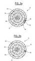
- Figs. 1a and 1billustrate cross sections of a fiber optic communication cable 5 having a side-emitting optical fiber 50 according to an exemplary embodiment of the present invention.
- the fiber optic communication cable 5preferably has an optical fiber 10, such as a step index single-mode or graded index multi-mode optical fiber with protective UV cured acrylate coating/cladding, a buffer 20 made of a buffer jacket material such as PVC, an aramid strength layer 30, and a cable jacket 40 made of a flexible insulating material, for example, PVC.
- a preferred embodimentutilizes a .250 mm outer diameter optical fiber 10 upjacked to a .900 mm outer diameter buffer 20.
- the fiber optic communication cable 5 of this embodimenthas a side-emitting optical fiber 50 disposed on an outer periphery of the aramid strength layer 30 and, as shown in Fig. 1a, is embedded in a translucent cable jacketing material 45.
- Aramid strength layer 30is preferably Dupont KEVLAR® or Akzo Twaron®.
- the translucent jacketing material 45is a flexible translucent insulating material, and allows the side emitting optical fiber to be observed therethrough.
- the remaining portion of cable jacket 40is made of a traditional opaque jacketing material, preferably a flame retardant PVC.
- Side emitting optical fibers 50are well known in the art and commercially available for a wide variety of uses. Some examples of commercially available side-emitting optical fibers are the Side Glow ® Fiber Optic Cable manufactured by Super Vision International, Inc. (http//www.svision.com), the side-emitting optical fibers available from Intelite, Inc. (http//www. intelite.com), and the V-grade Luminous side-emitting optical fibers available from Asahi Chemical Industry Co., Ltd. (http://www.asahi-kasei.co.jp). These side-emitting optical fibers are not used for transmission of data, as are ordinary optical fibers, but are used primarily for decorative purposes such as illuminating swimming pools, floor light, etc.
- the present inventionutilizes the luminescent advantages of the side-emitting optical fiber along with all the advantages of optical transmission fibers to provide a highly efficient and optically detectable transmission cable.
- the fiber optic communications cable 5 illustrated in Fig. 1b.is similar to that of Fig. 1a, except that the cable jacket is made completely of translucent jacketing material 45, thus the manufacturing process may be simplified as discussed in further detail below.
- Figs. 1c and 1dillustrate this embodiment where the side-emitting optical fiber 50 is positioned entirely underneath cable jacket 40.
- Figs. 1c and 1dexplicitly show this minor variation from Figs. 1a and 1d, the inventors contemplate the same in regard to any of the following embodiments.
- Figs. 2a and 2billustrate cross-sections of a fiber optic communication cable 5 according to a second embodiment of the present invention.
- the embodiment shown in Figs. 2a and 2bis similar to the first embodiment, except that the side-emitting optical fiber 50 is located on an outer perimeter of cable jacket 40, and an additional cable jacket 70 houses the side-emitting optical fiber 50 and is the outermost layer of the fiber optic communication cable 5.
- a portion of cable jacket 70is made of translucent material 75 for exposing the side-emitting optical fiber 50, while the remaining portion of cable jacket 70 is made of opaque jacketing material.
- the fiber optic communication cable illustrated in Fig. 2bis similar to that of Fig. 2a, except that the cable jacket 70 is made entirely from translucent material 75. In this manner, the manufacturing process may be simplified.
- One unique feature of the fiber optic communication cable 5 of the second embodimentis that a pre-existing fiber optic cable may be improved by adding a side-emitting optical fiber 50 to its periphery and enclose the cable in a translucent jacket to add optically detectable characteristics.
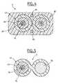
- Figs. 3a and 3billustrate cross sections of a dual fiber optic communications cable 6 having a side-emitting optical fiber 50 according to a third embodiment of the present invention.
- the cable jacket 40has a translucent portion 45, which joins the two optical fibers 10 and houses the side-emitting optical fiber 50 inside.
- the entire cable jacketmay be made of translucent material 45 to simplify a manufacturing process.
- Fig. 3cillustrates this embodiment where instead of placing the side-emitting optical fiber 50 in the middle portion of cable jacket 45, it is positioned underneath the cable jacket 45 of one of the optical fibers for transmission 50.
- Fig. 4illustrates a cross-section of a dual fiber optic communication cable 6 having two side-emitting optical fibers 50 according to a fourth embodiment of the present invention.
- two optical fibers 10 for transmissionare encapsulated in a translucent cable jacket 60 along with two side-emitting optical fibers 50.
- a communication cablemay be optically detected via the side-emitting optical fibers no matter which side of the cable that is exposed to an observer, as there is a side emitting optical fiber located on two sides of the communication cable.
- Fig. 5illustrates a modified fiber optic communication cable 5 having a side-emitting optical fiber 50.
- the communication cable 5is shown in a zip cord configuration with the side-emitting optical fiber 50 running adjacent to the optical fiber for transmission 10.
- the cable jacketis made entirely of translucent jacketing material 45.
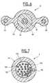
- Fig. 7illustrates a cross section of a modified cable 7 having a side-emitting optical fiber 50.
- electrical conductors 100are used as the means for conducting signals.
- Electrical conductors 100are twisted pairs having copper conductors 101 and insulators 102, although any known wiring configuration is contemplated, such as a solid power conductor, and power control cables.
- the modified cable 7may have a conductive shielding member 105 disposed between the twisted copper pairs and cable jacket 45 to reduce EM interference and prevent noise.
- Securing the side emitting fiber to the cablecan vary as shown in the case where the side emitting fiber can be under the jacket as in figure 1c-1d, encapsulated by the jacket material as shown in figure 1a-b, or barely encapsulated as shown in 2a-b.
- the inventorscontemplate all combinations of securing the side emitting fiber to the foregoing embodiments and any variations as mentioned.
- the cables having side-emitting optical fibershave been described above primarily in reference to fiber optic communication cables having side-emitting optical fibers.
- any of the embodimentsmay be equally implemented with electrically conductive cables, pneumatic tubes for conducting air or water, as well as any other type of longitudinal conduit in which it would be desirable to improve optical detectability. Examples of such embodiments are described below.
- the translucent jacketing material of the foregoing embodimentsmay be tinted with or without color shading pigment and allows the side emitting fibers to be seen when illuminated with a light source. Additionally, the side-emitting optical fibers of the present invention may be clear or tinted with color as both are commercially available.
- color-tinted translucent jacketing material or color tinted side-emitting optical fibers in a communication system having numerous optically detectable cables as shown in Fig. 8promotes the ability to illuminate the side-emitting fibers of multiple cables simultaneously while detecting an individual cable by observing the color of the light emanating from the respective cables.
- Fig. 8illustrates a generic communication system, for example, two patch panels, including a transmission unit 200, a receiving unit 300, and numerous optically detectable communication cables 400 connected therebetween to accommodate the transmission of communication signals.
- Each of the optically detectable communication cableshave side-emitting optical fibers 50, as illustrated by the cross section.
- the illustrated cross section of one of the optically detectable communication cables 400is similar to the fiber optic communication cable 5 illustrated in Fig 1, but could also be implemented via any of the contemplated cable configurations.
- the side-emitting optical fiber 50is embedded in translucent jacketing material 45 of the cable jacket 40.
- the translucent jacketing materialis designated as having a violet tint.
- optically detectable cableshave the same color, for example, clear
- individual cablesmay be optically distinguished by inputting detecting light into cable ends of the cables to be detect.
- the cable or cables to be detectedlight up along their respective axes.
- a method for detecting individual cables of a complex cabling systemfor example, the communication system of Fig. 8, is illustrated in Fig. 9.
- a light source or detector lightis positioned at an interface housing an end of a cable or cables to be detected.
- the cable endshave an adapter or interface to promote connection of the cable ends to different communication or wiring connection ports on the communications system.
- the communication systemmay have a detecting light source, such as an LED, laser, or incandescent lamp, built in to each of the connection ports so that disconnecting the cable to be detected from its respective connection port is not necessary.
- a detecting light sourcesuch as an LED, laser, or incandescent lamp
- the detecting light sourcetransmits light into the interface housing of the respective cables to be detected.
- a userobserves light emitted from the side-emitting optical fiber along an axis of the respective cables to be detected.
- a hand-held detecting lightmay be used.
- This hand-held detection light sourcemay either be adapted to be connected to the cable end interface, or by injecting the detecting light through the side of the cables 400 into the side-emitting optical fiber 50.
- a useris required to manually position the detecting light source at the interface housing an end of a cable or cables to be detected.
- the detecting lighttransmits light into the cables to be detected, and the user detects individual cables by observing light emitted along their axes.
- the hand-held detecting lightmay also be an LED, laser, or incandescent light source.
- multiple cablesmay be illuminated at one time and the cables are detected by the color of light emitted along their respective axes.
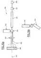
- FIG. 10aillustrates a cable forming device 500 for manufacturing the above-described cables.
- an optical fiberis drawn from a fiber payoff roll 510, along with aramid yarns from a plurality of aramid payoffs 530, and a side-emitting optical fiber from side-emitting fiber payoff 550, into a cable forming device.
- the strands of the respective payoffsare pulled through lay plate 560 and cross-head tip and die 565 by a pulling device 567 or capstan.
- a translucent jacketing material 45is extruded onto the fibers from extruder 540.
- the extruded cableis then pulled through cooling trough 566 and the finished cable is collected on take-up reel 568.
- the aforementioned manufacturing processproduces a cable having a side-emitting optical fiber and an entirely translucent cable jacket.
- Fig. 10bshows a modification to the cable forming machine for producing a cable having an opaque outer jacket where only a portion the cable jacket is made of translucent jacketing material 45.
- a second extruder 545is used with a striping tip to stripe the opaque cable jacket with a translucent portion.
- Dual extruders for striping cablesare well known in the art and thus are not explained in significant detail.
- Opaque jacketing materialsmay have flame retardant fillers, thus this option may serve to provide a more flame-resistant cable having a side-emitting optical fiber than that with an entirely translucent cabling jacket.
- the foregoing manufacturing method using cable manufacturing device 500is not limited to fiber optic cables, but may be used to produce electrical conductor cables as would be apparent to one of ordinary skill in the art.
- the cable manufacturing device 500may also be setup to pull more than one optical fiber or electrical conductor into a single cable or form any of the cable-embodiments described above.
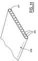
- FIG. 11illustrates an optical fiber ribbon 600 having a plurality of optical fibers 610 disposed inside the optical fiber ribbon 600.
- a side emitting optical fiber 611is disposed at a location of the ribbon 600 so that the location of the ribbon 600 may be determined, for example, in dense ribbon control panels.
- Another advantage of the side-emitting fiber in the ribbonis that it becomes a position identifier and a point to reference the other optical fibers from, when an operation such as splicing is desired. This allows for the operator or the splicing machine to detect/confirm that the fibers from each ribbon are aligned correctly without the operator having to use individual fiber colors or outer ribbon print markings to indicate the correct match-up.
- Fig. 12illustrates a hose 620 having a side-emitting optical fiber 621 disposed along the length of the hose 620.
- the hosemay be a conduit for air, water, gases, fluids or conductors, in which for example, it is desired to locate the hose at any point along its length in a dense hydraulic control box or panel.
- a hose coupling 622is disposed on an end of hose 620.
- Hose coupling 622has a coupling channel 623 for receiving the side-emitting optical fiber 621.
- a light source 624such as an LED, is positioned in the hose coupling 622 for providing light to the side-emitting optical fiber 621. Power can be provided through a light source connector 625 to illuminate light source 624.
- Fig. 13illustrates an embodiment where a MT-RJ cable is adapted for a side-emitting optical fiber.
- MT-RJ cablesare a common configuration of cables known in the art, thus detailed a description is omitted.
- an MT connector 720has a light source or switch 721 and a power source 722.
- the connector 720has a plurality of receiving holes for receiving the cable 700.
- the receiving holesmay include optical transmission fiber receiving holes 723 for transmission of data, a side-emitting optical fiber receiving hole 724 for receiving side-emitting optical fiber 705, and a conductor receiving hole 725 for providing power to cable conductor 710.
- Cable jackethas a translucent portion thereof to allow side-emitting optical fiber 705 to be observed therethrough.
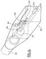
- Fig. 14illustrates one example of a side-emitting and optical fiber connector 800.
- a cable or conduit 810has a side-emitting optical fiber 820, and is capped with the connector 800.
- aramid 811surrounds a communications optical fiber 812 and is adapted for connection to a communications port by an optical fiber precision connector ceramic pin 813.
- Connector 800also has power source pins 814 which provide power to LED 825. Switch 830, when closed, provides power to LED 825 via power pins 814. In this manner, LED 825 illuminates and end of side-emitting optical fiber 820 for detection purposes.
- Connector 800is illustrated as a rectangular box to enhance drawing comprehension, but may be any number of shapes as the skilled artisan would recognize. Additionally, the connector 800 is provided only to promote understanding of a potential connection device, and can be adapted in numerous ways as would be apparent to one of ordinary skill.
Landscapes
- Physics & Mathematics (AREA)
- General Physics & Mathematics (AREA)
- Optics & Photonics (AREA)
- Engineering & Computer Science (AREA)
- Manufacturing & Machinery (AREA)
- Light Guides In General And Applications Therefor (AREA)
- Communication Cables (AREA)
Abstract
Description
The present invention relates to an optically detectable transmissioncable, method for manufacturing the same, and a method for identifyingoptically detectable cables in a complex cabling system. More particularly, thepresent invention relates to a transmission cable having a side-emittingoptical fiber included in a transparent or translucent cable jacket in order toassist in identifying the transmission cable at any point along its length.
Communication networks typically involve a distribution system inwhich main transmission lines are routed into a building or office to adistribution point. At the distribution point, several communication lines orcables are split from the main lines and directed into various sublevel systemsincluding wiring closets and patch panels, from which more cables aresubsequently routed to individual devices such as telephones, computers, faxmachines, etc.
Interconnections at the sublevel systems are also provided inconnection with switches and receiver/transmitter units at intervals along acommunication line for regenerating, for example, optical signals. Theseoptical/electrical interfaces, in connection with test equipment and monitoringdevices, at various sites within the system have large communication panelsto which large numbers of communication lines may be connected. A patchpanel may consist of several modules each having hundreds of input/outputadapters which are connected to numerous communication lines. Thesecommunication lines may consist of a bundles of cables with separated endsfor making individual connections.
Consequently, in such wiring systems, there are significantly largeamounts of cables present. Identification of individual cables becomesproblematic in that the cables may be intricately intertwined and/or positionedin inaccessible areas. The connections of these communication lines to andfrom the panels are often made by technicians, where the technician needs toidentify the cable and the adapter to which the cable is to be connected or disconnected. Because of the enormous amount of cables that may bepresent in such a complex cabling system, a technician may have difficultyfinding a particular cable to which an operation is to be performed. Therefore,there exists a need to efficiently identify individual cables of a complex cablingsystem at any point along the length of an individual cable.
Conventionally, it is well known in the art to provide cables with colorcoded stripes to assist in identifying individual cables. However, when asizeable number of cables are present, the number of color-coded cablesavailable may be insufficient. Thus, the color stripes of a complex cablingsystem are repetitively used, making identification of a particular cableimpossible. Additionally, in small enclosed spaces with poor lighting, such as awiring closet, it is difficult to ascertain one color from another.
It is therefore an object of the present invention to solve the foregoingproblems, by providing a cable which is easily identifiable along an entirelength, even when the cable is located in the vicinity of numerous othercables, and/or in a poorly lit environment. In order to achieve this object andothers, an optically observable cable is provided having a transmission cableand a side-emitting optical fiber disposed on a periphery of the transmissioncable and extending along a length of the transmission cable wherein thetransmission cable and side-emitting optical fiber are enclosed in at least apartially translucent cable jacket. The optically observable cable is illuminatedalong its entire length when light is provided at an end of the side-emittingoptical fiber, such that that the optically observable cable may be detected atany point along its length.
Another object of the present invention is to provide a communicationsystem having a plurality of optically detectable cables including atransmission unit for transmitting communication signals through the pluralityof optically detectable cables and a receiving unit for receiving the transmittedcommunication signals, wherein each of the optically detectable cablesincludes a conduit for conducting the communication signals, a side-emittingoptical fiber, and a cabling jacket housing the conduit and side-emitting optical fiber, wherein the cabling jacket has a translucent portion to allow theside-emitting optical fiber to be observed.
It is yet another object of the present invention to provide a methodfor detecting individual cables amongst a plurality of cables having side-emittingfibers by positioning a light source at an interface housing an end ofa cable to be detected, transmitting light from the light source into theinterface, and observing light emitted from the side-emitting optical fiber ofthe cable to be detected.
Yet a further object of the invention is to provide a method ofmanufacturing a cable having a side-emitting optical fiber by pulling a conduitfor conducting signals into a cable forming device, pulling a side-emittingoptical fiber into the cable forming device along side said conduit forconducting a signal, and extruding a cable jacket onto or around the conduitand side-emitting optical fiber as the conduit and the side-emitting opticalfiber are pulled into said cable forming device, wherein at least a portion ofsaid cable jacket is made of a translucent material to allow the side-emittingoptical fiber to be observed therethrough.
These and other objects of the invention will become apparent asdescribed below in reference to the appended drawings.
As described below in reference to the drawings, like referencenumerals are intended to represent like elements in the subsequentillustrations.
Figs. 1a and 1b illustrate cross sections of a fiberoptic communicationcable 5 having a side-emittingoptical fiber 50 according to an exemplaryembodiment of the present invention. The fiberoptic communication cable 5preferably has anoptical fiber 10, such as a step index single-mode or gradedindex multi-mode optical fiber with protective UV cured acrylatecoating/cladding, abuffer 20 made of a buffer jacket material such as PVC,anaramid strength layer 30, and acable jacket 40 made of a flexibleinsulating material, for example, PVC. A preferred embodiment utilizes a.250 mm outer diameteroptical fiber 10 upjacked to a .900 mmouterdiameter buffer 20.
The fiberoptic communication cable 5 of this embodiment has a side-emittingoptical fiber 50 disposed on an outer periphery of thearamid strength layer 30 and, as shown in Fig. 1a, is embedded in a translucent cablejacketingmaterial 45. Aramidstrength layer 30 is preferably DupontKEVLAR® or Akzo Twaron®. Thetranslucent jacketing material 45 is aflexible translucent insulating material, and allows the side emitting opticalfiber to be observed therethrough. The remaining portion ofcable jacket 40 ismade of a traditional opaque jacketing material, preferably a flame retardantPVC.
Side emittingoptical fibers 50 are well known in the art andcommercially available for a wide variety of uses. Some examples ofcommercially available side-emitting optical fibers are the Side Glow ® FiberOptic Cable manufactured by Super Vision International, Inc.(http//www.svision.com), the side-emitting optical fibers available fromIntelite, Inc. (http//www. intelite.com), and the V-grade Luminous side-emittingoptical fibers available from Asahi Chemical Industry Co., Ltd.(http://www.asahi-kasei.co.jp). These side-emitting optical fibers are not usedfor transmission of data, as are ordinary optical fibers, but are used primarilyfor decorative purposes such as illuminating swimming pools, floor light, etc.
The present invention utilizes the luminescent advantages of the side-emittingoptical fiber along with all the advantages of optical transmissionfibers to provide a highly efficient and optically detectable transmission cable.
The fiberoptic communications cable 5 illustrated in Fig. 1b. is similarto that of Fig. 1a, except that the cable jacket is made completely oftranslucent jacketing material 45, thus the manufacturing process may besimplified as discussed in further detail below. Figs. 1c and 1d illustrate thisembodiment where the side-emittingoptical fiber 50 is positioned entirelyunderneathcable jacket 40. Although Figs. 1c and 1d explicitly show thisminor variation from Figs. 1a and 1d, the inventors contemplate the same inregard to any of the following embodiments.
Figs. 2a and 2b illustrate cross-sections of a fiberoptic communicationcable 5 according to a second embodiment of the present invention. Theembodiment shown in Figs. 2a and 2b is similar to the first embodiment, except that the side-emittingoptical fiber 50 is located on an outer perimeterofcable jacket 40, and anadditional cable jacket 70 houses the side-emittingoptical fiber 50 and is the outermost layer of the fiberoptic communicationcable 5. In Fig. 2a, a portion ofcable jacket 70 is made oftranslucentmaterial 75 for exposing the side-emittingoptical fiber 50, while theremaining portion ofcable jacket 70 is made of opaque jacketing material.
The fiber optic communication cable illustrated in Fig. 2b is similar tothat of Fig. 2a, except that thecable jacket 70 is made entirely fromtranslucent material 75. In this manner, the manufacturing process may besimplified. One unique feature of the fiberoptic communication cable 5 of thesecond embodiment is that a pre-existing fiber optic cable may be improvedby adding a side-emittingoptical fiber 50 to its periphery and enclose thecable in a translucent jacket to add optically detectable characteristics.
Figs. 3a and 3b illustrate cross sections of a dual fiberopticcommunications cable 6 having a side-emittingoptical fiber 50 according to athird embodiment of the present invention. In this embodiment, there are twooptical fibers 10 for data transmission. As shown in Fig. 3a, thecable jacket 40, has atranslucent portion 45, which joins the twooptical fibers 10 andhouses the side-emittingoptical fiber 50 inside.
As with the previous embodiments, and as shown in Fig. 3b, the entirecable jacket may be made oftranslucent material 45 to simplify amanufacturing process. Fig. 3c illustrates this embodiment where instead ofplacing the side-emittingoptical fiber 50 in the middle portion ofcable jacket 45, it is positioned underneath thecable jacket 45 of one of the optical fibersfortransmission 50.
Fig. 4 illustrates a cross-section of a dual fiberoptic communicationcable 6 having two side-emittingoptical fibers 50 according to a fourthembodiment of the present invention. Here, twooptical fibers 10 fortransmission, are encapsulated in atranslucent cable jacket 60 along with twoside-emittingoptical fibers 50. In this embodiment, a communication cablemay be optically detected via the side-emitting optical fibers no matter which side of the cable that is exposed to an observer, as there is a side emittingoptical fiber located on two sides of the communication cable.
While the previous embodiments have only been described as usingone side-emittingoptical fiber 50, the inventors contemplate the use of two ormore side-emitting optical fibers in any of the embodiments described herein,as well as those that would be apparent to one with ordinary skill in the art.
Fig. 5 illustrates a modified fiberoptic communication cable 5 having aside-emittingoptical fiber 50. As illustrated, thecommunication cable 5 isshown in a zip cord configuration with the side-emittingoptical fiber 50running adjacent to the optical fiber fortransmission 10. Here, the cablejacket is made entirely oftranslucent jacketing material 45.
Fig. 6 illustrates a cross-section of a fiberoptic communication cable 5having a side emittingoptical fiber 50 and aconductor 80 according to a fifthembodiment of the present invention. Cable jacket is made fromtranslucentjacketing material 45, and encapsulates theoptical fiber 10 for transmission,the side-emittingoptical fiber 50, and theelectrical conductor 80, which maybe a copper wire. In this embodiment, thecommunication cable 5 is desirablefor applications which use both optical and electrical signal transmissions,such as a circuit where power is needed.
Fig. 7 illustrates a cross section of a modifiedcable 7 having a side-emittingoptical fiber 50. Here,electrical conductors 100 are used as themeans for conducting signals.Electrical conductors 100 are twisted pairshavingcopper conductors 101 andinsulators 102, although any known wiringconfiguration is contemplated, such as a solid power conductor, and powercontrol cables. Additionally, although not necessary, the modifiedcable 7 mayhave aconductive shielding member 105 disposed between the twistedcopper pairs andcable jacket 45 to reduce EM interference and prevent noise.
Securing the side emitting fiber to the cable can vary as shown in thecase where the side emitting fiber can be under the jacket as in figure 1c-1d,encapsulated by the jacket material as shown in figure 1a-b, or barelyencapsulated as shown in 2a-b. The inventors contemplate all combinations of securing the side emitting fiber to the foregoing embodiments and anyvariations as mentioned.
While specific fiber optic and electrical cables have been described inrespect to preferred embodiments, the inventors contemplate all combinationsof the foregoing embodiments and any variations which would be apparent toskilled artisans, but are too numerous to specifically describe.
For example, the cables having side-emitting optical fibers have beendescribed above primarily in reference to fiber optic communication cableshaving side-emitting optical fibers. However, one with ordinary skill in the artwould understand that any of the embodiments may be equally implementedwith electrically conductive cables, pneumatic tubes for conducting air orwater, as well as any other type of longitudinal conduit in which it would bedesirable to improve optical detectability. Examples of such embodiments aredescribed below.
The translucent jacketing material of the foregoing embodiments maybe tinted with or without color shading pigment and allows the side emittingfibers to be seen when illuminated with a light source. Additionally, the side-emittingoptical fibers of the present invention may be clear or tinted withcolor as both are commercially available.
Using color-tinted translucent jacketing material or color tinted side-emittingoptical fibers in a communication system having numerous opticallydetectable cables as shown in Fig. 8, promotes the ability to illuminate theside-emitting fibers of multiple cables simultaneously while detecting anindividual cable by observing the color of the light emanating from therespective cables.
Fig. 8 illustrates a generic communication system, for example, twopatch panels, including atransmission unit 200, a receivingunit 300, andnumerous opticallydetectable communication cables 400 connectedtherebetween to accommodate the transmission of communication signals.Each of the optically detectable communication cables have side-emittingoptical fibers 50, as illustrated by the cross section. Solely by way of example, the illustrated cross section of one of the opticallydetectablecommunication cables 400 is similar to the fiberoptic communication cable 5illustrated in Fig 1, but could also be implemented via any of thecontemplated cable configurations.
As shown in Fig. 5, the side-emittingoptical fiber 50 is embedded intranslucent jacketing material 45 of thecable jacket 40. Here, the translucentjacketing material is designated as having a violet tint. When a detecting lightis put into the ends of the opticallydetectable cables 400, the individual cableemitting a violet light along its axis may be easily detected amongst thevarious other cables present (i.e. red, blue, clear, green, etc).
However, if all the optically detectable cables have the same color, forexample, clear, individual cables may be optically distinguished by inputtingdetecting light into cable ends of the cables to be detect. The cable or cablesto be detected light up along their respective axes.
A method for detecting individual cables of a complex cabling system,for example, the communication system of Fig. 8, is illustrated in Fig. 9. Atstep S1, a light source or detector light is positioned at an interface housingan end of a cable or cables to be detected. Typically, the cable ends have anadapter or interface to promote connection of the cable ends to differentcommunication or wiring connection ports on the communications system.
The communication system may have a detecting light source, such asan LED, laser, or incandescent lamp, built in to each of the connection portsso that disconnecting the cable to be detected from its respective connectionport is not necessary. In this case, when initiated at step S2, the detectinglight source transmits light into the interface housing of the respective cablesto be detected. To detect individual cables at step S3, a user observes lightemitted from the side-emitting optical fiber along an axis of the respectivecables to be detected.
However, if the communication system does not have a built-indetecting light source, a hand-held detecting light may be used. This hand-helddetection light source may either be adapted to be connected to the cable end interface, or by injecting the detecting light through the side of thecables 400 into the side-emittingoptical fiber 50. Here, a user is required tomanually position the detecting light source at the interface housing an end ofa cable or cables to be detected. The detecting light transmits light into thecables to be detected, and the user detects individual cables by observinglight emitted along their axes. The hand-held detecting light may also be anLED, laser, or incandescent light source.
As previously stated, if various colors of translucent jacketing materialor side-emitting fibers are used for each cable, multiple cables may beilluminated at one time and the cables are detected by the color of lightemitted along their respective axes.
Now, a method of manufacturing a cable having side emitting opticalfiber will be explained. Fig. 10a illustrates acable forming device 500 formanufacturing the above-described cables. Here, an optical fiber is drawnfrom afiber payoff roll 510, along with aramid yarns from a plurality ofaramid payoffs 530, and a side-emitting optical fiber from side-emittingfiberpayoff 550, into a cable forming device. The strands of the respective payoffsare pulled throughlay plate 560 and cross-head tip and die 565 by a pullingdevice 567 or capstan. As the fibers are arranged by the lay plate andcompressed by the cross-head tip and die 565, atranslucent jacketingmaterial 45 is extruded onto the fibers fromextruder 540. The extruded cableis then pulled throughcooling trough 566 and the finished cable is collectedon take-upreel 568. The aforementioned manufacturing process produces acable having a side-emitting optical fiber and an entirely translucent cablejacket.
On the other hand, Fig. 10b shows a modification to the cable formingmachine for producing a cable having an opaque outer jacket where only aportion the cable jacket is made oftranslucent jacketing material 45. For thistype of cable, asecond extruder 545 is used with a striping tip to stripe theopaque cable jacket with a translucent portion. Dual extruders for stripingcables are well known in the art and thus are not explained in significant detail. Opaque jacketing materials may have flame retardant fillers, thus thisoption may serve to provide a more flame-resistant cable having a side-emittingoptical fiber than that with an entirely translucent cabling jacket.
The foregoing manufacturing method usingcable manufacturing device 500 is not limited to fiber optic cables, but may be used to produce electricalconductor cables as would be apparent to one of ordinary skill in the art. Thecable manufacturing device 500 may also be setup to pull more than oneoptical fiber or electrical conductor into a single cable or form any of thecable-embodiments described above.
Examples of other embodiments of conduits having side-emittingoptical fibers are illustrated in Figs. 11-13, respectively. Fig. 11 illustrates anoptical fiber ribbon 600 having a plurality ofoptical fibers 610 disposed insidetheoptical fiber ribbon 600. A side emittingoptical fiber 611 is disposed at alocation of theribbon 600 so that the location of theribbon 600 may bedetermined, for example, in dense ribbon control panels.
Another advantage of the side-emitting fiber in the ribbon, is that itbecomes a position identifier and a point to reference the other optical fibersfrom, when an operation such as splicing is desired. This allows for theoperator or the splicing machine to detect/confirm that the fibers from eachribbon are aligned correctly without the operator having to use individual fibercolors or outer ribbon print markings to indicate the correct match-up.
Fig. 12 illustrates ahose 620 having a side-emittingoptical fiber 621disposed along the length of thehose 620. The hose may be a conduit for air,water, gases, fluids or conductors, in which for example, it is desired to locatethe hose at any point along its length in a dense hydraulic control box orpanel. As illustrated, ahose coupling 622 is disposed on an end ofhose 620.Hose coupling 622 has acoupling channel 623 for receiving the side-emittingoptical fiber 621. Alight source 624, such as an LED, is positioned in thehosecoupling 622 for providing light to the side-emittingoptical fiber 621. Powercan be provided through alight source connector 625 to illuminatelightsource 624.
Fig. 13 illustrates an embodiment where a MT-RJ cable is adapted for aside-emitting optical fiber. MT-RJ cables are a common configuration of cablesknown in the art, thus detailed a description is omitted. Here, anMTconnector 720 has a light source or switch 721 and apower source 722. Theconnector 720 has a plurality of receiving holes for receiving thecable 700.The receiving holes may include optical transmissionfiber receiving holes 723for transmission of data, a side-emitting opticalfiber receiving hole 724 forreceiving side-emittingoptical fiber 705, and aconductor receiving hole 725for providing power tocable conductor 710. Cable jacket has a translucentportion thereof to allow side-emittingoptical fiber 705 to be observedtherethrough.
Fig. 14 illustrates one example of a side-emitting andoptical fiberconnector 800. As illustrated, a cable orconduit 810 has a side-emittingoptical fiber 820, and is capped with theconnector 800. Here,aramid 811surrounds a communicationsoptical fiber 812 and is adapted for connectionto a communications port by an optical fiber precision connectorceramic pin 813.Connector 800 also has power source pins 814 which provide power toLED 825.Switch 830, when closed, provides power toLED 825 via power pins814. In this manner,LED 825 illuminates and end of side-emittingopticalfiber 820 for detection purposes.
Although there have been described preferred embodiments of thisnovel invention, many variations and modifications are possible and theembodiments described herein are not limited by the specific disclosureabove, but rather should be limited only by the scope of the appended claims.
Claims (23)
- An optically observable cable comprising:
a transmission cable;a side-emitting optical fiber disposed on a periphery of saidtransmission cable and extending along a length of said transmission cable;anda cable jacket encapsulating said transmission cable and saidside-emitting optical fiber, wherein said cable jacket is at least partiallytranslucent. - The optically observable cable according to claim 1, wherein saidtransmission cable comprises a conduit for conducting signals, and aninsulating jacket.
- The optically observable cable according to claim 2, wherein saidconduit comprises an optical fiber.
- The optically observable cable according to claim 2, wherein saidconduit comprises an electrical conductor.
- An optically detectable cable comprising:a conduit for conducting a signal;a side emitting fiber optic fiber disposed adjacent to said conduitand running a length of said conduit; anda cable jacket disposed around said conduit and said sideemitting fiber, said cable jacket having a translucent portion thereof forallowing said side emitting fiber optic cable to be optically exposed throughsaid cable jacket.
- The optically detectable cable according to claim 5, wherein saidconduit for conducting said signal comprises an optical fiber and an aramiddisposed around said optical fiber.
- The optically detectable cable according to claim 5, wherein saidconduit comprises at least one electrical conductor.
- The optically detectable cable according to claim 7, wherein said atleast one electrical conductor is insulated with an insulating material, andwherein the insulated electrical conductor is housed by a conductive shieldingmember.
- The optically detectable cable according to claim 5, wherein thecable jacket is made entirely of a translucent material.
- An optically detectable conduit comprising:a longitudinal conduit;a side-emitting optical fiber disposed along a length of saidlongitudinal conduit; anda conduit jacket for housing said longitudinal conduit and side-emittingoptical fiber, said conduit jacket having at least a partially translucentportion thereof, so as to allow said side-emitting optical fiber to be opticallyexposed therethrough.
- The optically detectable conduit according to claim 10, whereinsaid optically detectable conduit is a ribbon cable, wherein said longitudinalconduit comprises a plurality of communication optical fibers, and whereinsaid side-emitting optical fiber is disposed along said plurality ofcommunication optical fibers as a position identifier and a point of referencefor said ribbon cable.
- A method for detecting individual cables from amongst a pluralityof signal transmission cables each having side-emitting optical fibers, saidmethod comprising:positioning a light source at an interface which houses an end ofa cable to be detected;transmitting light from said light source into said interface; andobserving light emitted along an axis of the cable to bedetected.
- The method for detecting individual cables according to claim 12,further comprising, identifying individual cables by a color of light emittedalong the axes of said plurality of signal transmission cables.
- A method for detecting individual cables from amongst a pluralityof signal transmission cables each having side-emitting optical fibers, saidmethod comprising:positioning a hand-held light source near a side-emitting opticalfiber located in a cable to be detected;injecting light from said hand-held light source into said side-emittingoptical fiber of said cable to be detected; andobserving light emitted along an axis of the cable to bedetected.
- A method of manufacturing a cable having a side-emitting opticalfiber comprising:(a) pulling a conduit for conducting signals into a cable formingdevice;(b) pulling a side-emitting optical fiber into the cable formingdevice along side said conduit for conducting a signal; and(c) extruding a cable jacket onto said conduit and side-emittingoptical fiber as said conduit and said side-emitting optical fiber are pulled intosaid cable forming device, wherein at least a portion of said cable jacket ismade of a translucent material to allow the side-emitting optical fiber to beobserved there through.
- The method of manufacturing the cable according to claim 15,wherein said conduit for conducting signals is a communications optical fiber.
- The method of manufacturing the cable according to claim 15,wherein said conduit for conducting signals is an electrical conductor.
- The method of manufacturing the cable according to claim 16,further comprising pulling a plurality of aramid yarns into the cable formingdevice such that said communications optical fiber is surrounded therewith toform a cable core, and the side-emitting optical fiber is disposed along side aperiphery of said cable core.
- The method of manufacturing the cable according to anyone ofclaims 15 to 18, wherein there are at least two conduits for conductingsignals.
- The method of manufacturing the cable according to anyone ofclaims 15 to 19, wherein there are at least two side-emitting optical fibers.
- A communication system having a plurality of optically detectablecables, said communication system comprising:a transmission unit for transmitting communication signalsthrough said plurality of optically detectable cables; anda receiving unit for receiving the transmitted communicationsignals, wherein each of said optically detectable cables comprises a conduitfor conducting said communication signals, a side emitting optical fiberdisposed adjacent to said conduit and running a length of said conduit; and acable jacket disposed around said conduit and said side emitting optical fiber,said cable jacket having a translucent portion thereof for allowing said sideemitting optical fiber to be optically exposed through said cable jacket.
- The communication system according to claim 21, wherein each ofthe translucent portions of the cable jackets of said plurality of opticallydetectable cables are various colors such that each of said plurality ofoptically detectable cable are distinguishable from one another.
- A connector for connecting an optically detectable cable having aconduit and a side-emitting optical fiber, said connector comprising:wherein said connector body includes an interface for interfacingsaid conduit with a desired conduit interface connection.a connector body for receiving an end of said opticallydetectable cable; anda light source disposed in said connector and adapted toilluminate the side-emitting optical fiber of said optically detectable cable;
Applications Claiming Priority (2)
| Application Number | Priority Date | Filing Date | Title |
|---|---|---|---|
| US09/604,972US6347172B1 (en) | 2000-06-28 | 2000-06-28 | Cable having side-emitting fiber under transparent or translucent cable jacket |
| US604972 | 2000-06-28 |
Publications (2)
| Publication Number | Publication Date |
|---|---|
| EP1168025A2true EP1168025A2 (en) | 2002-01-02 |
| EP1168025A3 EP1168025A3 (en) | 2002-01-09 |
Family
ID=24421755
Family Applications (1)
| Application Number | Title | Priority Date | Filing Date |
|---|---|---|---|
| EP01401601ACeasedEP1168025A3 (en) | 2000-06-28 | 2001-06-18 | Cable having side-emitting fiber under transparent or translucent cable jacket |
Country Status (2)
| Country | Link |
|---|---|
| US (1) | US6347172B1 (en) |
| EP (1) | EP1168025A3 (en) |
Cited By (21)
| Publication number | Priority date | Publication date | Assignee | Title |
|---|---|---|---|---|
| EP2345918A1 (en)* | 2010-01-19 | 2011-07-20 | Nexans | Optical fibre including an outer layer suitable for emitting visible light radiation |
| WO2013122825A1 (en)* | 2012-02-13 | 2013-08-22 | Corning Cable Systems Llc | Visual tracer system for fiber optic cable |
| WO2014200902A1 (en)* | 2013-06-10 | 2014-12-18 | Corning Optical Communications LLC | Optical fiber cable assembly comprising optical tracer fiber |
| WO2015023459A1 (en)* | 2013-08-12 | 2015-02-19 | Corning Optical Communications LLC | Optical fiber cable assembly comprising optical tracer fiber |
| US9304278B1 (en) | 2015-03-31 | 2016-04-05 | Corning Optical Communications LLC | Traceable cable with side-emitting optical fiber and method of forming the same |
| WO2016081298A1 (en)* | 2014-11-18 | 2016-05-26 | Corning Optical Communications LLC | Traceable optical fiber cable and filtered viewing device for enhanced traceability |
| EP3096077A1 (en)* | 2015-05-20 | 2016-11-23 | Corning Optical Communications LLC | Traceable cable with side-emitting optical fiber and method of forming the same |
| WO2017074670A1 (en)* | 2015-10-30 | 2017-05-04 | Corning Optical Communications LLC | Traceable cable assembly and connector |
| EP2557444A4 (en)* | 2010-04-05 | 2017-06-21 | Fujikura Co., Ltd. | Optical fiber tape core wire, optical fiber cable, and wiring pattern |
| EP3196893A4 (en)* | 2014-07-23 | 2017-08-02 | ZTE Corporation | Object recognition method and device |
| EP3211465A4 (en)* | 2014-10-20 | 2017-11-29 | ZTE Corporation | Quartz plastic composite optical fiber assembly, recognition method and device |
| CN107771295A (en)* | 2015-05-20 | 2018-03-06 | 康宁光电通信有限责任公司 | Traceable cable and its forming method with side launching fiber |
| US10107983B2 (en) | 2016-04-29 | 2018-10-23 | Corning Optical Communications LLC | Preferential mode coupling for enhanced traceable patch cord performance |
| US10185111B2 (en) | 2016-04-08 | 2019-01-22 | Corning Optical Communications LLC | Traceable end point cable assembly |
| US10222560B2 (en) | 2016-12-21 | 2019-03-05 | Corning Research & Development Corporation | Traceable fiber optic cable assembly with fiber guide and tracing optical fibers for carrying light received from a light launch device |
| US10228526B2 (en) | 2015-03-31 | 2019-03-12 | Corning Optical Communications LLC | Traceable cable with side-emitting optical fiber and method of forming the same |
| US10234614B2 (en) | 2017-01-20 | 2019-03-19 | Corning Research & Development Corporation | Light source assemblies and systems and methods with mode homogenization |
| US10338317B2 (en) | 2015-07-17 | 2019-07-02 | Corning Optical Communications LLC | Systems and methods for traceable cables |
| US10534135B2 (en) | 2015-07-17 | 2020-01-14 | Corning Optical Communications LLC | Systems and methods for tracing cables and cables for such systems and methods |
| US10539758B2 (en) | 2017-12-05 | 2020-01-21 | Corning Research & Development Corporation | Traceable fiber optic cable assembly with indication of polarity |
| US10539747B2 (en) | 2017-12-05 | 2020-01-21 | Corning Research & Development Corporation | Bend induced light scattering fiber and cable assemblies and method of making |
Families Citing this family (48)
| Publication number | Priority date | Publication date | Assignee | Title |
|---|---|---|---|---|
| GB9820854D0 (en)* | 1998-09-24 | 1998-11-18 | Lifor Limited | Fibre optic based directional way finding apparatus and method |
| US20020131121A1 (en)* | 2001-03-13 | 2002-09-19 | Muthu Jeganathan | Transceiver, system, and method for free-space optical communication and tracking |
| ATE433007T1 (en)* | 2002-05-02 | 2009-06-15 | Fatzer Ag | LUMINOUS ROPE |
| US20030210780A1 (en)* | 2002-05-10 | 2003-11-13 | Pratt Steven Duane | Device housing having one or more optical fibers |
| US6823120B2 (en) | 2002-07-31 | 2004-11-23 | Corning Cable Systems Llc | Transmit/receive optical cables |
| US7195561B2 (en)* | 2002-09-24 | 2007-03-27 | Intec, Inc. | Video game controller with illuminated cable |
| US20040223691A1 (en)* | 2003-03-10 | 2004-11-11 | Buelow Roger F. | Light pipe with directional side-light extraction |
| US7164819B2 (en)* | 2003-03-10 | 2007-01-16 | Fiberstars, Inc. | Side-light extraction by light pipe-surface alteration and light-extraction devices extending radially beyond the outer cladding |
| US7020369B2 (en)* | 2004-07-08 | 2006-03-28 | Berwick Offray Llc | Ribbon with fiber optics |
| SE528408C2 (en)* | 2005-03-07 | 2006-11-07 | Interactive Inst Ii Ab | A method and apparatus for visual indication of power or power consumption in an electrical cable |
| US7329857B1 (en) | 2006-03-01 | 2008-02-12 | Sandia Corporation | Side-emitting fiber optic position sensor |
| WO2009155037A2 (en) | 2008-05-28 | 2009-12-23 | Adc Telecommunications, Inc. | Fiber optic cable |
| WO2010062646A1 (en)* | 2008-10-28 | 2010-06-03 | Adc Telecommunications, Inc. | Flat drop cable |
| WO2011050181A2 (en) | 2009-10-21 | 2011-04-28 | Adc Telecommunications, Inc. | Flat drop cable with center strength member |
| US8475083B2 (en)* | 2010-03-31 | 2013-07-02 | University Court Of The University Of St. Andrews | Umbilical for underwater diving |
| WO2011143401A2 (en) | 2010-05-14 | 2011-11-17 | Adc Telecommunications, Inc. | Splice enclosure arrangement for fiber optic cables |
| WO2011146720A2 (en) | 2010-05-19 | 2011-11-24 | Adc Telecommunications, Inc. | Flat drop cable with medial bump |
| US8322871B1 (en)* | 2010-05-26 | 2012-12-04 | Telect, Inc. | Optical fiber tracing system |
| US8885998B2 (en) | 2010-12-09 | 2014-11-11 | Adc Telecommunications, Inc. | Splice enclosure arrangement for fiber optic cables |
| US9739966B2 (en) | 2011-02-14 | 2017-08-22 | Commscope Technologies Llc | Fiber optic cable with electrical conductors |
| JP6228110B2 (en) | 2011-04-28 | 2017-11-08 | エル イー エス エス・リミテッド | Waveguide device for illumination system |
| US8781281B2 (en) | 2011-07-21 | 2014-07-15 | Adc Telecommunications, Inc. | Drop cable with angled reinforcing member configurations |
| US8805141B2 (en) | 2011-10-07 | 2014-08-12 | Corning Incorporated | Optical fiber illumination systems and methods |
| US9974630B2 (en) | 2012-04-13 | 2018-05-22 | Orthoaccel Technologies, Inc. | Laser orthodontic devices |
| WO2013188973A1 (en)* | 2012-06-18 | 2013-12-27 | Universite Laval | Optogenetic probe |
| US9316802B2 (en) | 2012-08-24 | 2016-04-19 | Commscope Technologies Llc | Optical fiber cable having reinforcing layer of tape heat-bonded to jacket |
| US9557505B2 (en) | 2013-03-18 | 2017-01-31 | Commscope Technologies Llc | Power and optical fiber interface |
| CN105247805B (en) | 2013-03-18 | 2017-12-08 | 阿德斯电信公司 | Framework for wireless network |
| CN105247627B (en) | 2013-05-14 | 2018-08-10 | 阿德斯电信公司 | Power/Fiber Optic Hybrid Cable |
| EP3028085B1 (en) | 2013-07-29 | 2017-10-11 | Prysmian S.p.A. | Optical cable for terrestrial networks |
| US9213134B2 (en)* | 2013-08-06 | 2015-12-15 | Verizon Patent And Licensing Inc. | Alignment for splicing multi-core optical fibers |
| WO2015056220A1 (en) | 2013-10-18 | 2015-04-23 | Tissot Yann | Holder and systems for waveguide-based illumination |
| EP2871708B1 (en)* | 2013-11-07 | 2021-06-16 | Swisscom AG | Communication cable with illumination |
| CN105445872B (en)* | 2014-05-30 | 2018-12-07 | 徕心光电股份有限公司 | Optical cable module |
| CN105182484B (en)* | 2014-05-30 | 2018-09-25 | 徕心光电股份有限公司 | Optical cable module and method of manufacturing the same |
| WO2016001227A1 (en) | 2014-06-30 | 2016-01-07 | Koninklijke Philips N.V. | System for anti-biofouling |
| US9857515B2 (en) | 2014-07-28 | 2018-01-02 | Corning Incorporated | Side-emitting optical fiber system and assembly with light-emitting jacket members |
| WO2016096770A1 (en)* | 2014-12-16 | 2016-06-23 | Koninklijke Philips N.V. | A marine cable device adapted for the prevention of fouling |
| US10598880B2 (en) | 2015-03-04 | 2020-03-24 | Commscope Technologies Llc | Hybrid conduit system |
| JP6627486B2 (en)* | 2015-12-18 | 2020-01-08 | 日立金属株式会社 | Optical fiber cable and optical fiber cable identification method |
| US10793449B2 (en) | 2016-04-27 | 2020-10-06 | Arizona Board Of Regents On Behalf Of Arizona State University | Fiber-optic integrated membrane reactor |
| US10036867B2 (en) | 2016-08-31 | 2018-07-31 | International Business Machines Corporation | Illuminating cable for enhanced traceability |
| WO2018089623A1 (en) | 2016-11-09 | 2018-05-17 | Commscope, Inc. Of North Carolina | Exchangeable powered infrastructure module |
| CN108022690A (en)* | 2017-12-06 | 2018-05-11 | 山东太平洋光纤光缆有限公司 | A kind of pipe band laying optoelectronic composite cable and manufacture method |
| US11754778B2 (en) | 2018-11-21 | 2023-09-12 | Arizona Board Of Regents On Behalf Of Arizona State University | Photoresponsive polymer coated optical fibers for water treatment |
| CN110850539B (en)* | 2019-11-15 | 2021-03-16 | 烽火通信科技股份有限公司 | Optical signal-based identification optical cable and preparation method thereof |
| US12029826B2 (en) | 2021-02-08 | 2024-07-09 | Arizona Board Of Regents On Behalf Of Arizona State University | UV-C wavelength side-emitting optical fibers |
| EP4400762A1 (en)* | 2021-09-09 | 2024-07-17 | Kyocera Corporation | Light-emitting device |
Family Cites Families (11)
| Publication number | Priority date | Publication date | Assignee | Title |
|---|---|---|---|---|
| KR970004993B1 (en) | 1992-05-01 | 1997-04-10 | 스미도모덴기고오교오 가부시기가이샤 | Method for identifying an optical fiber using a pattern of reflected light |
| US5617497A (en)* | 1993-05-21 | 1997-04-01 | Super Vision International, Inc. | Lateral illumination fiber optic cable device and method of manufacture |
| US5577147A (en) | 1994-03-31 | 1996-11-19 | Lucent Technologies Inc. | Magnetically locatable optical fiber cables containing integrated magnetic marker materials |
| IL113674A (en) | 1995-05-09 | 1998-06-15 | Laser Ind Ltd | Side-emitting optical fibers for lasers with orientation markings |
| EP0961901A1 (en)* | 1996-01-19 | 1999-12-08 | Lumenyte International Corporation | Side lighting optical conduit |
| US5708499A (en) | 1996-07-24 | 1998-01-13 | Lucent Technologies Inc. | Optical components for live-fiber identifier and coupler |
| US5995702A (en)* | 1997-04-08 | 1999-11-30 | Roblon A/S | Side radiating cable with increased light output |
| US5905837A (en) | 1997-07-22 | 1999-05-18 | Nec Usa, Inc. | Side emitting optical fiber |
| US5982967A (en)* | 1997-12-12 | 1999-11-09 | Lucent Technologies Inc. | Color-coded optical fiber cable and a method for manufacturing the same |
| EP0939274A3 (en)* | 1998-02-25 | 2000-05-24 | Koninklijke Philips Electronics N.V. | Fibre optical cable with lateral diffusion of light |
| US6275644B1 (en)* | 1998-12-15 | 2001-08-14 | Transmatic, Inc. | Light fixture including light pipe having contoured cross-section |
- 2000
- 2000-06-28USUS09/604,972patent/US6347172B1/ennot_activeExpired - Fee Related
- 2001
- 2001-06-18EPEP01401601Apatent/EP1168025A3/ennot_activeCeased
Cited By (33)
| Publication number | Priority date | Publication date | Assignee | Title |
|---|---|---|---|---|
| FR2955399A1 (en)* | 2010-01-19 | 2011-07-22 | Nexans | OPTICAL FIBER COMPRISING AN OUTER LAYER CAPABLE OF TRANSMITTING VISIBLE LUMINOUS RADIATION |
| EP2345918A1 (en)* | 2010-01-19 | 2011-07-20 | Nexans | Optical fibre including an outer layer suitable for emitting visible light radiation |
| EP2557444A4 (en)* | 2010-04-05 | 2017-06-21 | Fujikura Co., Ltd. | Optical fiber tape core wire, optical fiber cable, and wiring pattern |
| US9671551B2 (en) | 2012-02-13 | 2017-06-06 | Corning Optical Communications LLC | Visual tracer system for fiber optic cable |
| CN104169771B (en)* | 2012-02-13 | 2018-05-29 | 康宁光电通信有限责任公司 | For the vision tracker system of optical cable |
| WO2013122825A1 (en)* | 2012-02-13 | 2013-08-22 | Corning Cable Systems Llc | Visual tracer system for fiber optic cable |
| CN104169771A (en)* | 2012-02-13 | 2014-11-26 | 康宁光电通信有限责任公司 | Visual tracer system for fiber optic cable |
| US8620123B2 (en) | 2012-02-13 | 2013-12-31 | Corning Cable Systems Llc | Visual tracer system for fiber optic cable |
| WO2014200902A1 (en)* | 2013-06-10 | 2014-12-18 | Corning Optical Communications LLC | Optical fiber cable assembly comprising optical tracer fiber |
| WO2015023459A1 (en)* | 2013-08-12 | 2015-02-19 | Corning Optical Communications LLC | Optical fiber cable assembly comprising optical tracer fiber |
| US9429731B2 (en) | 2013-08-12 | 2016-08-30 | Corning Optical Communications LLC | Optical fiber cable assembly comprising optical tracer fiber |
| EP3196893A4 (en)* | 2014-07-23 | 2017-08-02 | ZTE Corporation | Object recognition method and device |
| EP3211465A4 (en)* | 2014-10-20 | 2017-11-29 | ZTE Corporation | Quartz plastic composite optical fiber assembly, recognition method and device |
| US10107974B2 (en) | 2014-10-20 | 2018-10-23 | Zte Corporation | Quartz plastic composite optical fiber assembly, recognition method and device |
| US10379309B2 (en) | 2014-11-18 | 2019-08-13 | Corning Optical Communications LLC | Traceable optical fiber cable and filtered viewing device for enhanced traceability |
| WO2016081298A1 (en)* | 2014-11-18 | 2016-05-26 | Corning Optical Communications LLC | Traceable optical fiber cable and filtered viewing device for enhanced traceability |
| US10228526B2 (en) | 2015-03-31 | 2019-03-12 | Corning Optical Communications LLC | Traceable cable with side-emitting optical fiber and method of forming the same |
| US9304278B1 (en) | 2015-03-31 | 2016-04-05 | Corning Optical Communications LLC | Traceable cable with side-emitting optical fiber and method of forming the same |
| CN107771295A (en)* | 2015-05-20 | 2018-03-06 | 康宁光电通信有限责任公司 | Traceable cable and its forming method with side launching fiber |
| US10101553B2 (en) | 2015-05-20 | 2018-10-16 | Corning Optical Communications LLC | Traceable cable with side-emitting optical fiber and method of forming the same |
| EP3096077A1 (en)* | 2015-05-20 | 2016-11-23 | Corning Optical Communications LLC | Traceable cable with side-emitting optical fiber and method of forming the same |
| US10338317B2 (en) | 2015-07-17 | 2019-07-02 | Corning Optical Communications LLC | Systems and methods for traceable cables |
| US10534135B2 (en) | 2015-07-17 | 2020-01-14 | Corning Optical Communications LLC | Systems and methods for tracing cables and cables for such systems and methods |
| WO2017074670A1 (en)* | 2015-10-30 | 2017-05-04 | Corning Optical Communications LLC | Traceable cable assembly and connector |
| US10101545B2 (en) | 2015-10-30 | 2018-10-16 | Corning Optical Communications LLC | Traceable cable assembly and connector |
| US10185111B2 (en) | 2016-04-08 | 2019-01-22 | Corning Optical Communications LLC | Traceable end point cable assembly |
| US10107983B2 (en) | 2016-04-29 | 2018-10-23 | Corning Optical Communications LLC | Preferential mode coupling for enhanced traceable patch cord performance |
| US10222561B2 (en) | 2016-12-21 | 2019-03-05 | Corning Research & Development Corporation | Light launch device for transmitting light into a traceable fiber optic cable assembly with tracing optical fibers |
| US10222560B2 (en) | 2016-12-21 | 2019-03-05 | Corning Research & Development Corporation | Traceable fiber optic cable assembly with fiber guide and tracing optical fibers for carrying light received from a light launch device |
| US10545298B2 (en) | 2016-12-21 | 2020-01-28 | Corning Research & Development Corporation | Traceable fiber optic cable assembly with illumination structure and tracing optical fibers for carrying light received from a light launch device |
| US10234614B2 (en) | 2017-01-20 | 2019-03-19 | Corning Research & Development Corporation | Light source assemblies and systems and methods with mode homogenization |
| US10539758B2 (en) | 2017-12-05 | 2020-01-21 | Corning Research & Development Corporation | Traceable fiber optic cable assembly with indication of polarity |
| US10539747B2 (en) | 2017-12-05 | 2020-01-21 | Corning Research & Development Corporation | Bend induced light scattering fiber and cable assemblies and method of making |
Also Published As
| Publication number | Publication date |
|---|---|
| EP1168025A3 (en) | 2002-01-09 |
| US6347172B1 (en) | 2002-02-12 |
Similar Documents
| Publication | Publication Date | Title |
|---|---|---|
| US6347172B1 (en) | Cable having side-emitting fiber under transparent or translucent cable jacket | |
| US9671551B2 (en) | Visual tracer system for fiber optic cable | |
| US5463706A (en) | Light traceable transmission conduit assembly | |
| US20180172925A1 (en) | Traceable end point cable assembly having a tracing waveguide | |
| US5666453A (en) | Fiber optic jumper cables and tracing method using same | |
| WO2005106899A1 (en) | An optically traceable transmission cable for transmitting data or electricity and a traceable conduit | |
| US9176295B2 (en) | Stranded optical cable with connectors | |
| WO2008048955A2 (en) | Patch cord with a light pipe | |
| US20050052174A1 (en) | Traceable patch cable and connector assembly and method for identifying patch cable ends | |
| WO2014035022A1 (en) | Fusion splicer having added optical fiber inspection function | |
| KR101879390B1 (en) | Device for identifying optical line with optical fiber cables | |
| US20090087152A1 (en) | Optical Cable, Arrangement for Connecting a Multiplicity of Optical Waveguides, and Method for Manufacturing an Optical Cable | |
| EP3211465B1 (en) | Quartz plastic composite optical fiber assembly, recognition method and device | |
| KR102068185B1 (en) | cable structure including optic fiber cable | |
| CN114063231B (en) | Optical fiber distribution panel capable of identifying fiber core and short-distance communication system | |
| CN216749443U (en) | Multi-core easy-to-separate photoelectric hybrid cable for indoor wiring | |
| JP2019066889A (en) | Fiber optic cable | |
| KR100516822B1 (en) | Optical Jumer Code | |
| CN109357844B (en) | Quick line hunting system of visible light | |
| KR100576152B1 (en) | Optical signal detector | |
| CN221101103U (en) | Optical fiber jumper wire for recognizing photoelectric end head | |
| KR100320369B1 (en) | Multi-fiber jumper cord | |
| CN210427866U (en) | Optical fiber movable connector | |
| KR20200010885A (en) | Optical And Power Composite Cable And Optical And Power Composite Jumper Cord | |
| KR20230001302U (en) | Multi-core optical cable for an environment of complicated bundle use |
Legal Events
| Date | Code | Title | Description |
|---|---|---|---|
| PUAI | Public reference made under article 153(3) epc to a published international application that has entered the european phase | Free format text:ORIGINAL CODE: 0009012 | |
| PUAL | Search report despatched | Free format text:ORIGINAL CODE: 0009013 | |
| AK | Designated contracting states | Kind code of ref document:A2 Designated state(s):AT BE CH CY DE DK ES FI FR GB GR IE IT LI LU MC NL PT SE TR | |
| AX | Request for extension of the european patent | Free format text:AL;LT;LV;MK;RO;SI | |
| AK | Designated contracting states | Kind code of ref document:A3 Designated state(s):AT BE CH CY DE DK ES FI FR GB GR IE IT LI LU MC NL PT SE TR | |
| AX | Request for extension of the european patent | Free format text:AL;LT;LV;MK;RO;SI | |
| 17P | Request for examination filed | Effective date:20020709 | |
| AKX | Designation fees paid | Free format text:AT BE CH CY DE DK ES FI FR GB GR IE IT LI LU MC NL PT SE TR | |
| 17Q | First examination report despatched | Effective date:20081128 | |
| STAA | Information on the status of an ep patent application or granted ep patent | Free format text:STATUS: THE APPLICATION HAS BEEN REFUSED | |
| 18R | Application refused | Effective date:20100701 |