EP1167754A2 - Turning device for the rotor of a wind turbine - Google Patents
Turning device for the rotor of a wind turbineDownload PDFInfo
- Publication number
- EP1167754A2 EP1167754A2EP01115171AEP01115171AEP1167754A2EP 1167754 A2EP1167754 A2EP 1167754A2EP 01115171 AEP01115171 AEP 01115171AEP 01115171 AEP01115171 AEP 01115171AEP 1167754 A2EP1167754 A2EP 1167754A2
- Authority
- EP
- European Patent Office
- Prior art keywords
- toothed
- shaft
- tool
- toothed disc
- locking element
- Prior art date
- Legal status (The legal status is an assumption and is not a legal conclusion. Google has not performed a legal analysis and makes no representation as to the accuracy of the status listed.)
- Granted
Links
- 230000005540biological transmissionEffects0.000claimsdescription3
- 230000001154acute effectEffects0.000claimsdescription2
- 238000007654immersionMethods0.000claims1
- 238000009434installationMethods0.000description3
- 208000012886VertigoDiseases0.000description2
- 230000008878couplingEffects0.000description2
- 238000010168coupling processMethods0.000description2
- 238000005859coupling reactionMethods0.000description2
- 238000004519manufacturing processMethods0.000description2
- 102000011842Serrate-Jagged ProteinsHuman genes0.000description1
- 108010036039Serrate-Jagged ProteinsProteins0.000description1
- 230000000712assemblyEffects0.000description1
- 238000000429assemblyMethods0.000description1
- 230000015572biosynthetic processEffects0.000description1
- 230000035939shockEffects0.000description1
Images


Classifications
- F—MECHANICAL ENGINEERING; LIGHTING; HEATING; WEAPONS; BLASTING
- F01—MACHINES OR ENGINES IN GENERAL; ENGINE PLANTS IN GENERAL; STEAM ENGINES
- F01D—NON-POSITIVE DISPLACEMENT MACHINES OR ENGINES, e.g. STEAM TURBINES
- F01D25/00—Component parts, details, or accessories, not provided for in, or of interest apart from, other groups
- F01D25/34—Turning or inching gear
- F01D25/36—Turning or inching gear using electric motors
- F—MECHANICAL ENGINEERING; LIGHTING; HEATING; WEAPONS; BLASTING
- F03—MACHINES OR ENGINES FOR LIQUIDS; WIND, SPRING, OR WEIGHT MOTORS; PRODUCING MECHANICAL POWER OR A REACTIVE PROPULSIVE THRUST, NOT OTHERWISE PROVIDED FOR
- F03D—WIND MOTORS
- F03D13/00—Assembly, mounting or commissioning of wind motors; Arrangements specially adapted for transporting wind motor components
- F03D13/10—Assembly of wind motors; Arrangements for erecting wind motors
- F—MECHANICAL ENGINEERING; LIGHTING; HEATING; WEAPONS; BLASTING
- F03—MACHINES OR ENGINES FOR LIQUIDS; WIND, SPRING, OR WEIGHT MOTORS; PRODUCING MECHANICAL POWER OR A REACTIVE PROPULSIVE THRUST, NOT OTHERWISE PROVIDED FOR
- F03D—WIND MOTORS
- F03D80/00—Details, components or accessories not provided for in groups F03D1/00 - F03D17/00
- F03D80/50—Maintenance or repair
- F—MECHANICAL ENGINEERING; LIGHTING; HEATING; WEAPONS; BLASTING
- F05—INDEXING SCHEMES RELATING TO ENGINES OR PUMPS IN VARIOUS SUBCLASSES OF CLASSES F01-F04
- F05B—INDEXING SCHEME RELATING TO WIND, SPRING, WEIGHT, INERTIA OR LIKE MOTORS, TO MACHINES OR ENGINES FOR LIQUIDS COVERED BY SUBCLASSES F03B, F03D AND F03G
- F05B2230/00—Manufacture
- F05B2230/60—Assembly methods
- F—MECHANICAL ENGINEERING; LIGHTING; HEATING; WEAPONS; BLASTING
- F05—INDEXING SCHEMES RELATING TO ENGINES OR PUMPS IN VARIOUS SUBCLASSES OF CLASSES F01-F04
- F05B—INDEXING SCHEME RELATING TO WIND, SPRING, WEIGHT, INERTIA OR LIKE MOTORS, TO MACHINES OR ENGINES FOR LIQUIDS COVERED BY SUBCLASSES F03B, F03D AND F03G
- F05B2260/00—Function
- F05B2260/30—Retaining components in desired mutual position
- F05B2260/31—Locking rotor in position
- F—MECHANICAL ENGINEERING; LIGHTING; HEATING; WEAPONS; BLASTING
- F05—INDEXING SCHEMES RELATING TO ENGINES OR PUMPS IN VARIOUS SUBCLASSES OF CLASSES F01-F04
- F05D—INDEXING SCHEME FOR ASPECTS RELATING TO NON-POSITIVE-DISPLACEMENT MACHINES OR ENGINES, GAS-TURBINES OR JET-PROPULSION PLANTS
- F05D2230/00—Manufacture
- F05D2230/60—Assembly methods
- Y—GENERAL TAGGING OF NEW TECHNOLOGICAL DEVELOPMENTS; GENERAL TAGGING OF CROSS-SECTIONAL TECHNOLOGIES SPANNING OVER SEVERAL SECTIONS OF THE IPC; TECHNICAL SUBJECTS COVERED BY FORMER USPC CROSS-REFERENCE ART COLLECTIONS [XRACs] AND DIGESTS
- Y02—TECHNOLOGIES OR APPLICATIONS FOR MITIGATION OR ADAPTATION AGAINST CLIMATE CHANGE
- Y02E—REDUCTION OF GREENHOUSE GAS [GHG] EMISSIONS, RELATED TO ENERGY GENERATION, TRANSMISSION OR DISTRIBUTION
- Y02E10/00—Energy generation through renewable energy sources
- Y02E10/70—Wind energy
- Y02E10/72—Wind turbines with rotation axis in wind direction
- Y—GENERAL TAGGING OF NEW TECHNOLOGICAL DEVELOPMENTS; GENERAL TAGGING OF CROSS-SECTIONAL TECHNOLOGIES SPANNING OVER SEVERAL SECTIONS OF THE IPC; TECHNICAL SUBJECTS COVERED BY FORMER USPC CROSS-REFERENCE ART COLLECTIONS [XRACs] AND DIGESTS
- Y02—TECHNOLOGIES OR APPLICATIONS FOR MITIGATION OR ADAPTATION AGAINST CLIMATE CHANGE
- Y02P—CLIMATE CHANGE MITIGATION TECHNOLOGIES IN THE PRODUCTION OR PROCESSING OF GOODS
- Y02P70/00—Climate change mitigation technologies in the production process for final industrial or consumer products
- Y02P70/50—Manufacturing or production processes characterised by the final manufactured product
Definitions
- the inventionrelates to a device for rotating a rotor or coupled shaft of a wind turbine. Such a device is used in particular for single sheet assembly and for replacement individual blades of the rotor of the wind turbine are required.
- the rotoris rotated with the help of a special drive unit that is located between the gearbox and the generator is arranged and with the "fast" wave, so is connected to the transmission output shaft. That kind of rotation
- the rotoris very tool-intensive and because of the installation and removal of the Drive unit also quite time consuming.
- the inventionis based on the object of a device for rotating a with a rotor connected or coupled shaft of a wind turbine to create, which is characterized by a simplified structure and for the Standard tools can be used.
- a shaft of a wind power plantuses a tool which has a rotationally drivable drive shaft.
- This toolis fixed with its housing to a holding element, which in turn on a component of the wind turbine with the exception of the shaft and attachable to parts connected to the shaft.
- On the drive shafta pinion is attached to the tool, which meshes with a toothed disc, which can be connected to the shaft.
- the toolis either a hand-operated tool or a motor tool (e.g. a drill). in the latter case are particularly suitable for motor-driven screwdrivers (so called torque wrenches) while as hand operated tools especially creaking or ratchet wrenches. hand-operated
- motor-driven screwdriversso called torque wrenches
- hand operated toolsespecially creaking or ratchet wrenches.
- toolsare only used in wind turbines Diameters of smaller rotors can be used.
- the attachment of the tool to the holding element of the inventionis expediently brought into engagement with one another Gears on the tool housing and on the holding element. So they point commercially available screwdrivers for tightening and loosening screw nuts in the area of the end of the drive shaft that receives the nut concentric external gear part, which in a corresponding Internal toothing part of a through hole of the holding element can be inserted is. In this way, the housing is uncomplicated and simply non-rotatable Holding element stored. On that facing away from the housing of the tool Side of the holding element protruding end of the drive shaft then mesh the pinion with the toothed disc.
- the toothed disk provided according to the inventionis particularly advantageous as a brake disc for a parking disc brake of the wind turbine is trained.
- Wind turbineshave several of the lag braking devices serving to rotate the rotor. They are in general equipped with a disc brake on the "fast" Shaft is arranged. Because of the lower torque of the "fast” Shaft it is an advantage if the tooth lock washer is on the "fast” shaft is arranged. Because then the tool only needs a comparatively small one Apply torque to the rotor even in the event of an imbalance to be able to rotate.
- the toothed disk of the device according to the inventioncan have helical teeth exhibit. Furthermore, the teeth can be substantially radial from the Protruding toothed lock washer or at an acute angle to the radial extent run, as is the case with a bevel gear. Finally the teeth can also protrude axially from the pulley. Training of the pinion corresponds to the formation of the teeth of the toothed disc. In the case of a conical toothed lock washer, the pinion should also be conical his. Depending on the space available in the machine housing, one of the previously mentioned variants of the toothed disc and pinion can be used. Finally, the special design of the toothed disc and pinion also depends depends on how the holding element and in particular the tool relative to Toothed washer can be arranged, which is also not least of all depending on the space available in the machine housing of the wind turbine is.
- the device according to the inventioncan, as already described above, use especially when mounting a single blade rotor.
- the device according to the inventioncan also be used in connection with the replacement of individual rotor blades can be used. Focus when replacing individual rotor blades, however, it is necessary to determine the rotor, to secure against unwanted rotation.
- locking elements in the form of longitudinally displaceable locking bolts usedwhich immerse in axial or radial holes in the brake disc.
- a certain disadvantage of these systemsis that the Brake disc can only be determined in a few rotational positions and that taking up these rotational positions can be problematic.
- the locking elementtherefore expediently points to his the teeth of the toothed disc end at least one projection on the in the locking position of the locking element between two teeth of the Immersed toothed lock washer. It is useful if instead of a projection there are several projections on the locking element, which then, by the way also a single protrusion, comb with the toothed lock washer.
- the locking elementcan be moved towards and away from the teeth of the toothed disk guided on a guide part that on a component or a component the wind turbine with the exception of the shaft and the toothed washer as well other elements connected to the shaft is mounted.
- Locking elementin its locking position and its release position To secure against unwanted movements, it is advantageous if that Locking element can be fixed on the guide part in these two positions.
- the locking elementis moved between the two positions expediently with the help of a hand crank.
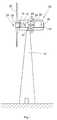
- Fig. 1shows a side view of a wind turbine 10 with some of its essentials Assemblies.
- the wind turbine 10has a tower 12 on which A machine housing 14 (nacelle) mounted rotatably about a vertical axis is arranged. Inside the machine housing 14 is the so-called “Slow” shaft 16 is rotatably supported by a shaft bearing 18. On the wave 16, the hub 20 of a rotor 24 having a plurality of rotor blades 22 is attached.
- the “slow” shaft 16is connected to a gear 26, the is housed in the machine housing 14.
- the gear 26is so called “fast” shaft 28 connected to a generator 30.
- On the Shaft 28is a parking disc brake 32 with a brake disc 34.
- the Disc brakewith a device 36 for locking the brake disc 34 and combined with a device 38 for rotating the brake disc 34.
- Figs. 2-4is the device 36 for locking the brake disk 34 shown. Furthermore, some details of the disc brake are also in the figures 32 recognizable.
- This disc brake 32has two brake shoes 40 on (only one of these two brake shoes can be seen in the figures), which axially towards and by means of a pressing device 42 on the brake disc 34 are movable away. These components of the disc brake 32 are on one Retaining element 44 attached, which via the screws 46 on the housing of the Gear 26 is attached.
- the brake disc 34is provided with teeth 50 on its circumference 48.
- This toothing 50consists of a plurality of radially projecting teeth.
- the brake disc 34is a toothed disc 52.
- the Locking element 54has on its opposite the toothed disc 52 End 56 on two projections 58 which are designed in the manner of teeth 60, which can dip between the teeth 50 of the toothed disk 52.
- Fig. 2is the locking element 54 in dashed lines and in its release position shown in which it is out of engagement with the toothed disc 52.
- Fig. 3shows the locking position of the locking element 54, in its Teeth 50 are immersed between the teeth 50 of the toothed disk 52. Further 3 and 4 show different sectional views to illustrate the Structure of the locking device 36.
- the locking device 36is provided with a mounting part 62 which over the Screws 64 is attached to the housing of the transmission 26.
- a guide part 66On the assembly part 62 is a guide part 66, which consists of two side parts 68 and a central part which springs back relative to these two side parts 68 70 exists.
- the two side parts 68are connected to one another via a cover part 72 connected.
- the locking element 54In the space between the parts 68 to 72 the locking element 54 is guided radially to the toothed disk 52.
- the movement of the Locking element 54takes place with the help of a hand crank 74, which is on a rear Plate 76 of the guide member 66 is rotatably mounted.
- Hand crank 74can be a shaft 77 provided with an external thread twist that in threaded engagement with an internally threaded bore 78 of the locking element 54 stands. Accordingly, by turning the crank handle 74 Locking element 54, due to its rectangular cross-sectional shape Twists are securely arranged in the guide part 66, moved back and forth.
- the locking element 54can be by means of a spring-loaded locking pin 80 both in its locking position as well as in its release position on the guide part 66 or on the latter Set cover part 72. This prevents it from shocks to an unwanted rotation of the crank handle 74 and thus to one Movement of the locking element 54 comes.
- the spring-loaded locking bolt 80engages one of two receiving bores 82 in the locking element 54.
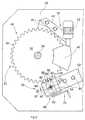
- FIG 5 and 6show the attachment of the device 38 for rotating the brake or. Toothed washer 34, 52 on the guide part 66.
- the Cover part 72 with the locking pin 80removed from the guide part 66 and a plate-shaped holding part 84 screwed to the side parts 68 of the guide part 66.
- This holding part 84has a radially outward toothing 50 of FIG Toothed disk 52 arranged through opening 86 with a ring 88 with Internal teeth 89 on.
- An external toothing elementis in the through opening 86 90 of an electrically operated torque screwdriver 92 can be used, with its housing 94, the external toothing element 90 is firmly connected is.
- the drive shaftruns coaxially with the external toothing element 90 96, the coupling end in this case designed as an outer square is.
- a pinion 98whose teeth 100 mesh with the teeth 50 of the toothed disk 52.
- the pinion 98is against an unintentional detachment from the drive shaft 96 is supported on the latter. This is done for example by radial screwing, pinning, Bolting or the like
Landscapes
- Engineering & Computer Science (AREA)
- Mechanical Engineering (AREA)
- General Engineering & Computer Science (AREA)
- Life Sciences & Earth Sciences (AREA)
- Sustainable Development (AREA)
- Sustainable Energy (AREA)
- Chemical & Material Sciences (AREA)
- Combustion & Propulsion (AREA)
- Wind Motors (AREA)
Abstract
Description
Translated fromGermanDie Erfindung betrifft eine Vorrichtung zum Drehen einer mit einem Rotor verbundenenoder gekoppelten Welle einer Windkraftanlage. Eine derartige Vorrichtungwird insbesondere für die Einzelblattmontage und für die Auswechslungeinzelner Blätter des Rotors der Windkraftanlage benötigt.The invention relates to a device for rotating a rotoror coupled shaft of a wind turbine. Such a deviceis used in particular for single sheet assembly and for replacementindividual blades of the rotor of the wind turbine are required.
Bei der Installation einer Windkraftanlage wird der Rotor auf dem Boden liegendvormontiert und danach als eine Einheit mittels eines Krans an der"langsamen" Welle des auf dem Turm befindlichen Maschinengehäuses(Gondel) angebracht. Diese Vorgehensweise hat sich bewährt, setzt jedochvoraus, dass um den Turm der Windkraftanlage herum ausreichend Platz vorhandenist. Unter beengten Verhältnissen und insbesondere bei Off-Shore-Windkraftanlagenist diese Art der Montage des Rotors nicht möglich. In solchenFällen bedient man sich der Einzelblattmontage, bei der zunächst dieNabe an die "langsame" Welle des Maschinengehäuses angebracht und alsdanndie einzelnen Rotorblätter an der Nabe befestigt werden. Da die Rotorblattbefestigungentweder unter vertikaler oder horizontaler Ausrichtung desRotorblattes erfolgt, muss der Rotor nach jeder Blattmontage gedreht werden,um das nächste Rotorblatt anbringen zu können. Die Drehung des Rotors erfolgtdabei mit Hilfe eines speziellen Antriebsaggregats, das zwischen dem Getriebeund dem Generator angeordnet wird und mit der "schnellen" Welle, alsomit der Ausgangswelle des Getriebes verbunden wird. Diese Art der Drehungdes Rotors ist recht werkzeugintensiv und wegen des Ein- und Ausbaus desAntriebsaggregats auch recht zeitaufwendig.When installing a wind turbine, the rotor is lying on the groundpre-assembled and then as a unit by means of a crane on the"slow" shaft of the machine housing on the tower(Gondola) attached. This approach has proven itself, but continuesthat there is sufficient space around the tower of the wind turbineis. In cramped conditions and especially in off-shore wind turbinesthis type of rotor assembly is not possible. In suchCases use single sheet assembly, in which theHub attached to the "slow" shaft of the machine housing and thenthe individual rotor blades are attached to the hub. Because the rotor blade attachmentwith either the vertical or horizontal orientation of theRotor blade occurs, the rotor must be turned after each blade assembly,to be able to attach the next rotor blade. The rotor is rotatedwith the help of a special drive unit that is located between the gearboxand the generator is arranged and with the "fast" wave, sois connected to the transmission output shaft. That kind of rotationThe rotor is very tool-intensive and because of the installation and removal of theDrive unit also quite time consuming.
Der Erfindung liegt die Aufgabe zu Grunde, eine Vorrichtung zum Drehen einermit einem Rotor verbundenen oder gekoppelten Welle einer Windkraftanlage zu schaffen, die sich durch einen vereinfachten Aufbau auszeichnet und für dieStandardwerkzeuge verwendet werden können.The invention is based on the object of a device for rotating awith a rotor connected or coupled shaft of a wind turbineto create, which is characterized by a simplified structure and for theStandard tools can be used.
Zur Lösung dieser Aufgabe wird mit der Erfindung eine Vorrichtung zumDrehen einer mit einem Rotor verbundenen oder gekoppelten Welle einerWindkraftanlage vorgeschlagen, die versehen ist mit
- einer Zahnscheibe, die mit der Welle verbindbar ist,
- einem Halteelement, das an einer Komponente der Windkraftanlage mitAusnahme der Zahnscheibe und der Welle anbringbar ist,
- einem Werkzeug mit einer drehend antreibbaren Antriebswelle und einemGehäuse, das an dem Halteelement ortsfest anbringbar ist, und
- einem Ritzel zum Befestigen an der Antriebswelle des Werkzeuges, wobeidas Ritzel in seinem an der Antriebswelle des Werkzeuges befestigten Zustandund bei an dem Halteelement angebrachten Gehäuse des Werkzeugesmit der Zahnscheibe kämmt.
- a toothed lock washer that can be connected to the shaft,
- a holding element which can be attached to a component of the wind power plant with the exception of the toothed disk and the shaft,
- a tool with a rotatably drivable drive shaft and a housing which can be fixedly attached to the holding element, and
- a pinion for attachment to the drive shaft of the tool, the pinion meshing with the toothed disk in its state fastened to the drive shaft of the tool and with the housing of the tool attached to the holding element.
Als Werkzeug zum Antreiben der mit dem Rotor verbundenen oder gekoppeltenWelle einer Windkraftanlage wird erfindungsgemäß ein Werkzeug verwendet,das eine drehend antreibbare Antriebswelle aufweist. Dieses Werkzeugwird mit seinem Gehäuse ortsfest an einem Halteelement angebracht, das seinerseitsan einer Komponente der Windkraftanlage mit Ausnahme der Welleund mit der Welle verbundenen Teilen anbringbar ist. Auf der Antriebswelledes Werkzeuges wird ein Ritzel befestigt, das mit einer Zahnscheibe kämmt,die mit der Welle verbindbar ist. Mit dieser konstruktiv recht einfachen undmontagefreundlichen Vorrichtung lässt sich nun die Welle und damit der Rotordrehen, und zwar auch dann, wenn der Rotor auf Grund des Fehlens ein odermehrerer Rotorblätter eine starke Unwucht aufweist.As a tool to drive those connected or coupled to the rotorAccording to the invention, a shaft of a wind power plant uses a toolwhich has a rotationally drivable drive shaft. This toolis fixed with its housing to a holding element, which in turnon a component of the wind turbine with the exception of the shaftand attachable to parts connected to the shaft. On the drive shafta pinion is attached to the tool, which meshes with a toothed disc,which can be connected to the shaft. With this constructively quite simple andThe shaft and thus the rotor can now be installed with ease of installationturn, even if the rotor due to the lack of one orseveral rotor blades has a strong imbalance.
Bei dem Werkzeug handelt es sich entweder um ein handbetriebenes Werkzeugoder um ein motorisches Werkzeug (beispielsweise Bohrmaschine). Imletztgenannten Fall eignen sich insbesondere motorisch betriebene Schrauber(so genannte Drehmomentschrauber), während als handbetriebene Werkzeuge insbesondere Knarren oder Ratschenschlüssel in Frage kommen. HandbetriebeneWerkzeuge sind allerdings lediglich bei Windkraftanlagen mit imDurchmesser kleineren Rotoren einsetzbar.The tool is either a hand-operated toolor a motor tool (e.g. a drill). in thethe latter case are particularly suitable for motor-driven screwdrivers(so called torque wrenches) while as hand operated toolsespecially creaking or ratchet wrenches. hand-operatedHowever, tools are only used in wind turbinesDiameters of smaller rotors can be used.
Die Anbringung des Werkzeugs an dem Halteelement der erfindungsgemäßenVorrichtung erfolgt zweckmäßigerweise durch in Eingriff miteinander bringbareVerzahnungen am Werkzeuggehäuse und am Halteelement. So weisen diehandelsüblichen Schrauber zum Festziehen und Lösen von Schraubenmutternim Bereich des der Aufnahme der Nuss dienenden Endes der Antriebswelle einkonzentrisches Außenverzahnungsteil auf, das in ein korrespondierendesInnenverzahnungsteil eines Durchgangsloches des Halteelements einsteckbarist. Auf diese Weise ist das Gehäuse unkompliziert und einfach drehfest amHalteelement gelagert. Auf das an der dem Gehäuse des Werkzeuges abgewandtenSeite des Halteelements überstehenden Ende der Antriebswelle lässtsich dann das Ritzel mit der Zahnscheibe kämmend aufsetzen.The attachment of the tool to the holding element of the inventionThe device is expediently brought into engagement with one anotherGears on the tool housing and on the holding element. So they pointcommercially available screwdrivers for tightening and loosening screw nutsin the area of the end of the drive shaft that receives the nutconcentric external gear part, which in a correspondingInternal toothing part of a through hole of the holding element can be insertedis. In this way, the housing is uncomplicated and simply non-rotatableHolding element stored. On that facing away from the housing of the toolSide of the holding element protruding end of the drive shaftthen mesh the pinion with the toothed disc.
Die Sicherung des Ritzels an und die Kupplung des Ritzels mit der Antriebswelleerfolgt in ähnlicher Weise wie es bei einer auf die Antriebswelle aufsteckbarenNuss der Fall ist.Securing the pinion and coupling the pinion to the drive shafttakes place in a similar manner to that which can be plugged onto the drive shaftNut is the case.
Besonders vorteilhaft ist es, wenn die erfindungsgemäß vorgesehene Zahnscheibeals Bremsscheibe für eine Feststell-Scheibenbremse der Windkraftanlageausgebildet ist. Windkraftanlagen verfügen über mehrere der Verzögerungder Rotation des Rotors dienenden Bremsvorrichtungen. Sie sind im allgemeinenmit einer Scheibenbremse ausgestattet, die auf der "schnellen"Welle angeordnet ist. Wegen des geringeren Drehmoments der "schnellen"Welle ist es von Vorteil, wenn auch die Zahnscheibe auf der "schnellen" Welleangeordnet ist. Denn dann braucht das Werkzeug nur ein vergleichsweise geringesDrehmoment aufzubringen, um den Rotor auch im Falle einer Unwuchtdrehen zu können. Aus Gründen der Platzersparnis und der Herstellungskostenist es nun zweckmäßig, die zumeist vorhandene Bremsscheibe gezahnt unddamit als Zahnscheibe auszubilden, um dann diese Zahnscheibe sowohl zum Bremsen des Rotors als auch zum Antreiben des Rotors im Falle der Installation,Montage und Demontage der Rotorblätter verwenden zu können.It when the toothed disk provided according to the invention is particularly advantageousas a brake disc for a parking disc brake of the wind turbineis trained. Wind turbines have several of the lagbraking devices serving to rotate the rotor. They are in generalequipped with a disc brake on the "fast"Shaft is arranged. Because of the lower torque of the "fast"Shaft it is an advantage if the tooth lock washer is on the "fast" shaftis arranged. Because then the tool only needs a comparatively small oneApply torque to the rotor even in the event of an imbalanceto be able to rotate. For reasons of space saving and manufacturing costsit is now appropriate to serrate the usually existing brake disc andto train as a toothed washer, then this toothed washer both forBraking the rotor as well as driving the rotor in case of installation,To be able to use assembly and disassembly of the rotor blades.
Die Zahnscheibe der erfindungsgemäßen Vorrichtung kann eine Schrägverzahnungaufweisen. Ferner können die Zähne im wesentlichen radial von derZahnscheibe abstehen oder aber auch unter einem spitzen Winkel zur Radialerstreckungverlaufen, wie es bei einem Kegelzahnrad der Fall ist. Schließlichkönnen die Zähne auch axial von der Zahnscheibe abstehen. Die Ausbildungdes Ritzels ist korrespondierend zur Ausbildung der Zähne der Zahnscheibe.Im Falle einer Kegel-Zahnscheibe sollte auch das Ritzel kegelförmig ausgebildetsein. Je nach den Platzverhältnissen im Maschinengehäuse kann eine derzuvor genannten Varianten der Zahnscheibe nebst Ritzel eingesetzt werden.Schließlich hängt die spezielle Ausgestaltung von Zahnscheibe und Ritzel auchdavon ab, wie das Halteelement und insbesondere das Werkzeug relativ zurZahnscheibe angeordnet werden kann, was ebenfalls nicht zuletzt auch vonden Platzverhältnissen im Maschinengehäuse der Windkraftanlage abhängigist.The toothed disk of the device according to the invention can have helical teethexhibit. Furthermore, the teeth can be substantially radial from theProtruding toothed lock washer or at an acute angle to the radial extentrun, as is the case with a bevel gear. Finallythe teeth can also protrude axially from the pulley. Trainingof the pinion corresponds to the formation of the teeth of the toothed disc.In the case of a conical toothed lock washer, the pinion should also be conicalhis. Depending on the space available in the machine housing, one of thepreviously mentioned variants of the toothed disc and pinion can be used.Finally, the special design of the toothed disc and pinion also dependsdepends on how the holding element and in particular the tool relative toToothed washer can be arranged, which is also not least of alldepending on the space available in the machine housing of the wind turbineis.
Die erfindungsgemäße Vorrichtung lässt sich, wie vorstehend bereits beschrieben,insbesondere bei der Einzelblattmontage eines Rotors einsetzen. Darüberhinaus kann die erfindungsgemäße Vorrichtung auch im Zusammenhang mitder Auswechslung einzelner Rotorblätter verwendet werden. Hauptaugenmerkbei der Auswechslung einzelner Rotorblätter ist es jedoch, den Rotor festzustellen,also gegen eine ungewollte Drehung zu sichern. Hierzu werden imStand der Technik Arretierelemente in Form von längsverschiebbaren Arretierbolzeneingesetzt, die in axiale oder radiale Bohrungen der Bremsscheibe eintauchen.Ein gewisser Nachteil dieser Systeme besteht darin, dass sich dieBremsscheibe lediglich in einigen wenigen Drehstellungen feststellen lässt unddass das Einnehmen dieser Drehstellungen mitunter problematisch ist.The device according to the invention can, as already described above,use especially when mounting a single blade rotor. About thatIn addition, the device according to the invention can also be used in connection withthe replacement of individual rotor blades can be used. focuswhen replacing individual rotor blades, however, it is necessary to determine the rotor,to secure against unwanted rotation. For this purpose, inState of the art locking elements in the form of longitudinally displaceable locking boltsused, which immerse in axial or radial holes in the brake disc.A certain disadvantage of these systems is that theBrake disc can only be determined in a few rotational positions andthat taking up these rotational positions can be problematic.
Nachdem erfindungsgemäß bereits eine Zahnscheibe auf der Welle vorhandenist, ist es zweckmäßig, deren Verzahnung nunmehr auch zum Sperren, d.h. zum Feststellen der Zahnscheibe und damit auch zum Feststellen des Rotorszu verwenden. Das Arretierelement weist also zweckmäßigerweise an seinemden Zähnen der Zahnscheibe zugewandten Ende mindestens einen Vorsprungauf, der in der Feststellposition des Arretierelements zwischen zwei Zähne derZahnscheibe eintaucht. Zweckmäßig ist es, wenn anstelle eines Vorsprungsmehrere Vorsprünge am Arretierelement vorhanden sind, die dann, wie übrigensauch ein einzelner Vorsprung, mit der Zahnscheibe kämmen. Das Arretierelementist auf die Zähne der Zahnscheibe zu und von diesen weg bewegbaran einem Führungsteil geführt, das an einem Bauteil oder einer Komponenteder Windkraftanlage mit Ausnahme der Welle und der Zahnscheibe sowieanderen mit der Welle verbundenen Elementen gelagert ist.After a toothed disc already exists on the shaft according to the inventionit is expedient to interlock them now for locking, i.e.to lock the lock washer and thus to lock the rotorto use. The locking element therefore expediently points to histhe teeth of the toothed disc end at least one projectionon the in the locking position of the locking element between two teeth of theImmersed toothed lock washer. It is useful if instead of a projectionthere are several projections on the locking element, which then, by the wayalso a single protrusion, comb with the toothed lock washer. The locking elementcan be moved towards and away from the teeth of the toothed diskguided on a guide part that on a component or a componentthe wind turbine with the exception of the shaft and the toothed washer as wellother elements connected to the shaft is mounted.
Um das Arretierelement in seiner Arretierungsposition und seiner Freigabepositiongegen ungewollte Bewegungen zu sichern, ist es von Vorteil, wenn dasArretierelement am Führungsteil in diesen beiden Positionen festlegbar ist. DasVerfahren des Arretierelements zwischen den beiden Positionen erfolgtzweckmäßigerweise mit Hilfe einer Handkurbel.Around the locking element in its locking position and its release positionTo secure against unwanted movements, it is advantageous if thatLocking element can be fixed on the guide part in these two positions. TheThe locking element is moved between the two positionsexpediently with the help of a hand crank.
Wie vorstehend beschrieben, lässt ich also die Zahnscheibe auf konstruktiveinfache und montage- sowie bedienerfreundliche Weise mit einer Arretiervorrichtungkombinieren. Unter dem Gesichtspunkt der Herstellungskosten ist esvon Vorteil, wenn die Teile der erfindungsgemäßen Vorrichtung zum Drehendes Rotors mit Ausnahme der Zahnscheibe erst im Bedarfsfall montiert werden.Für die Montage des Halteelements eignet sich dann insbesondere dasFührungsteil, an dem das Arretierelement geführt ist. Denn auch dieses Führungsteilist im Bereich der Verzahnung der Zahnscheibe angeordnet; in diesemBereich muss auch das Werkzeug zum Drehen der Zahnscheibe mittelsdes Ritzels angeordnet werden. Nicht zuletzt auch aus Platzgründen solltenalso sowohl die Arretiervorrichtung als auch die Drehvorrichtung nahe beieinanderangeordnet sein.As described above, I leave the pulley on constructivelysimple and easy to assemble and operate with a locking devicecombine. From the point of view of manufacturing costs, it isadvantageous if the parts of the device according to the invention for turningof the rotor with the exception of the toothed lock washer should only be installed if necessary.This is particularly suitable for mounting the holding elementGuide part on which the locking element is guided. Because this guide part toois arranged in the area of the toothing of the toothed disc; in thisThe area must also use the tool to turn the toothed lock washerof the pinion. Not least for reasons of spaceSo both the locking device and the rotating device close to each otherbe arranged.
Nachfolgend wird anhand der Figuren ein Ausführungsbeispiel der Erfindungnäher erläutert. Im einzelnen zeigen:
- Fig. 1
- in Seitenansicht eine Windkraftanlage zur Verdeutlichung der Positioninnerhalb des Maschinengehäuses, an der die erfindungsgemäßeDrehvorrichtung anzubringen ist,
- Fig. 2
- eine Ansicht entlang der Linie II-II der Fig. 1 auf die Feststell-Scheibenbremsemit Umfangszahnung zum wahlweisen Feststellen oderDrehen der Bremsscheibe, wobei in Fig. 2 neben der Feststell-Scheibenbremsedie Vorrichtung zur Arretierung der Bremsscheibe dargestelltist,
- Fig. 3
- eine Darstellung ähnlich der gemäß Fig. 2 jedoch mit aufgeschnittenerArretiervorrichtung,
- Fig. 4
- einen Schnitt durch die Arretiervorrichtung gemäß IV-IV der Fig. 2,
- Fig. 5
- eine Darstellung ähnlich der in Fig. 2 jedoch mit an der Arretiervorrichtungbefestigter Vorrichtung zum Drehen der Bremsscheibe und
- Fig. 6
- eine Darstellung auf die Bremsscheibe mit Drehvorrichtung gemäßdem Pfeil VI der Fig. 5.
- Fig. 1
- a side view of a wind power plant to illustrate the position within the machine housing at which the rotating device according to the invention is to be attached,
- Fig. 2
- 2 shows a view along the line II-II of FIG. 1 of the locking disc brake with circumferential toothing for optional locking or turning of the brake disc, the device for locking the brake disc being shown in FIG. 2 in addition to the locking disc brake,
- Fig. 3
- 2 shows a representation similar to that of FIG. 2, but with the locking device cut open,
- Fig. 4
- 3 shows a section through the locking device according to IV-IV of FIG. 2,
- Fig. 5
- a representation similar to that in Fig. 2 but with the locking device attached to the device for rotating the brake disc and
- Fig. 6
- a representation of the brake disc with a rotating device according to the arrow VI of FIG .. 5
Fig. 1 zeigt in Seitenansicht eine Windkraftanlage 10 mit einigen ihrer wesentlichenBaugruppen. Die Windkraftanlage 10 weist einen Turm 12 auf, auf demum eine Vertikalachse drehbar gelagert ein Maschinengehäuse 14 (Gondel)angeordnet ist. Innerhalb des Maschinengehäuses 14 ist die so genannte"langsame" Welle 16 über ein Wellenlager 18 drehbar gelagert. An der Welle16 ist die Nabe 20 eines mehrere Rotorblätter 22 aufweisenden Rotors 24 angebracht.Die "langsame" Welle 16 ist mit einem Getriebe 26 verbunden, dasim Maschinengehäuse 14 untergebracht ist. Das Getriebe 26 ist über die so genannte "schnelle" Welle 28 mit einem Generator 30 verbunden. Auf derWelle 28 befindet sich eine Feststell-Scheibenbremse 32 mit einer Bremsscheibe34. Bei diesem Ausführungsbeispiel der Windkraftanlage 10 ist dieScheibenbremse mit einer Vorrichtung 36 zum Arretieren der Bremsscheibe 34und mit einer Vorrichtung 38 zum Verdrehen der Bremsscheibe 34 kombiniert.Diese Vorrichtungen werden nachfolgend anhand der Fign. 2 bis 6 erläutert.Fig. 1 shows a side view of a
In den Fign. 2 bis 4 ist die Vorrichtung 36 zum Arretieren der Bremsscheibe 34dargestellt. Ferner sind in den Figuren auch einige Einzelheiten der Scheibenbremse32 zu erkennen. Diese Scheibenbremse 32 weist zwei Bremsbacken 40auf (in den Figuren ist lediglich eine dieser beiden Bremsbacken zu erkennen),die mittels einer Anpressvorrichtung 42 axial auf die Bremsscheibe 34 zu- undwegbewegbar sind. Diese Komponenten der Scheibenbremse 32 sind an einemHalteelement 44 angebracht, das über die Schrauben 46 an dem Gehäuse desGetriebes 26 befestigt ist.In Figs. 2-4 is the
Die Bremsscheibe 34 ist an ihrem Umfang 48 mit einer Zahnung 50 versehen.Diese Zahnung 50 besteht aus einer Vielzahl von radial abstehenden Zähnen.Insoweit handelt es sich bei der Bremsscheibe 34 um eine Zahnscheibe 52. Mitden Zähnen 50 dieser Zahnscheibe 52 wirkt ein Arretierelement 54 zusammen,das radial auf die Zahnscheibe 52 zu und von dieser weg bewegbar ist. DasArretierelement 54 weist an seinem der Zahnscheibe 52 gegenüberliegendenEnde 56 zwei Vorsprünge 58 auf, die nach Art von Zähnen 60 ausgebildet sind,welche zwischen die Zähne 50 der Zahnscheibe 52 eintauchen können. In Fig.2 ist das Arretierelement 54 in gestrichelten Linien und in seiner Freigabepositiondargestellt, in der es außer Eingriff mit der Zahnscheibe 52 steht.The
Fig. 3 zeigt die Arretierungsposition des Arretierelements 54, in der seineZähne 50 zwischen die Zähne 50 der Zahnscheibe 52 eingetaucht sind. Fernerzeigen Fig. 3 und 4 verschiedenen Schnittansichten zur Verdeutlichung desAufbaus der Arretiervorrichtung 36.Fig. 3 shows the locking position of the locking
Die Arretiervorrichtung 36 ist mit einem Montageteil 62 versehen, das über dieSchrauben 64 an dem Gehäuse des Getriebes 26 befestigt ist. Auf dem Montageteil62 befindet sich ein Führungsteil 66, das aus zwei Seitenteilen 68 undeinem gegenüber diesen beiden Seitenteilen 68 zurückspringenden Mittelteil70 besteht. Die beiden Seitenteile 68 sind über ein Deckelteil 72 miteinanderverbunden. In dem sich zwischen den Teilen 68 bis 72 ergebenden Raum istdas Arretierelement 54 radial zur Zahnscheibe 52 geführt. Die Bewegung desArretierelements 54 erfolgt mit Hilfe einer Handkurbel 74, die an einer rückwärtigenPlatte 76 des Führungsteils 66 drehbar gelagert ist. Mit Hilfe derHandkurbel 74 lässt sich eine mit einem Außengewinde versehene Welle 77verdrehen, die in Gewindeeingriff mit einer Innengewindebohrung 78 des Arretierelements54 steht. Durch Drehen der Handkurbel 74 wird demzufolge dasArretierelement 54, das auf Grund seiner rechteckigen Querschnittsform gegenVerdrehungen gesichert im Führungsteil 66 angeordnet ist, vor- und zurückbewegt.The locking
Wie anhand von Fig. 4 zu erkennen ist, lässt sich das Arretierelement 54 mittelseines federbelasteten Feststellbolzens 80 sowohl in seiner Arretierungspositionals auch in seiner Freigabeposition am Führungsteil 66 bzw. an dessenDeckelteil 72 festlegen. Dadurch wird verhindert, dass es durch Erschütterungenzu einer ungewollten Verdrehung der Handkurbel 74 und damit zu einerBewegung des Arretierelements 54 kommt. Der federbelastete Feststellbolzen80 greift eine von zwei Aufnahmebohrungen 82 im Arretierelement 54.As can be seen from FIG. 4, the locking
Fig. 5 und 6 zeigen den Anbau der Vorrichtung 38 zum Verdrehen der Brems-bzw.Zahnscheibe 34,52 an dem Führungsteil 66. Zu diesem Zweck wird dasDeckelteil 72 mit dem Feststellbolzen 80 vom Führungsteil 66 entfernt und einplattenförmiges Halteteil 84 mit den Seitenteilen 68 des Führungsteils 66 verschraubt.Dieses Halteteil 84 weist eine radial auswärts der Zahnung 50 derZahnscheibe 52 angeordnete Durchgangsöffnung 86 mit einem Ring 88 mitInnenverzahnung 89 auf. In die Durchgangsöffnung 86 ist ein Außenverzahnungselement90 eines elektrisch betriebenen Drehmomentschraubers 92 einsetzbar, mit dessen Gehäuse 94 das Außenverzahnungselement 90 fest verbundenist. Koaxial zum Außenverzahnungselement 90 verläuft die Antriebswelle96, deren Kupplungsende in diesem Fall als Außenvierkant ausgebildetist. Auf die Antriebswelle 96 ist ein Ritzel 98 aufgesteckt, dessen Zähne 100mit der Verzahnung 50 der Zahnscheibe 52 kämmen. Das Ritzel 98 ist gegenein unbeabsichtigtes Ablösen von der Antriebswelle 96 auf dieser gelagert.Dies erfolgt beispielsweise durch eine radiale Verschraubung, Verstiftelung,Verbolzung o.dgl.5 and 6 show the attachment of the
Bei Betrieb des Drehmomentschraubers 92 dreht sich das Ritzel 98, welchesinfolge dessen die Bremsscheibe 34 drehend antreibt. Somit lässt sich der mitder Welle 28 über das Getriebe 26 und die Welle 16 gekoppelte Rotor 24 mitHilfe des Drehmomentschraubers 92 in die für die Montage bzw. Auswechslungder Rotorblätter jeweils erforderliche Stellung verdrehen.When the
Claims (15)
Translated fromGermanApplications Claiming Priority (2)
| Application Number | Priority Date | Filing Date | Title |
|---|---|---|---|
| DE10031473 | 2000-06-28 | ||
| DE10031473ADE10031473C1 (en) | 2000-06-28 | 2000-06-28 | Device for rotating a shaft of a wind power plant connected or coupled to a rotor |
Publications (3)
| Publication Number | Publication Date |
|---|---|
| EP1167754A2true EP1167754A2 (en) | 2002-01-02 |
| EP1167754A3 EP1167754A3 (en) | 2007-03-14 |
| EP1167754B1 EP1167754B1 (en) | 2016-08-10 |
Family
ID=7647086
Family Applications (1)
| Application Number | Title | Priority Date | Filing Date |
|---|---|---|---|
| EP01115171.9AExpired - LifetimeEP1167754B1 (en) | 2000-06-28 | 2001-06-22 | Turning device for the rotor of a wind turbine |
Country Status (3)
| Country | Link |
|---|---|
| EP (1) | EP1167754B1 (en) |
| DE (1) | DE10031473C1 (en) |
| DK (1) | DK1167754T3 (en) |
Cited By (31)
| Publication number | Priority date | Publication date | Assignee | Title |
|---|---|---|---|---|
| EP1659286A1 (en)* | 2004-11-18 | 2006-05-24 | Eickhoff Maschinenfabrik GmbH | Turning device for a wind generator power train |
| ITMI20081340A1 (en)* | 2008-07-23 | 2010-01-24 | Rolic Invest Sarl | WIND GENERATOR |
| WO2009140954A3 (en)* | 2008-05-21 | 2010-04-15 | Innovative Windpower Ag | Device for fixing a rotor in an electric machine |
| US7808149B2 (en) | 2004-09-20 | 2010-10-05 | Wilic S.Ar.L. | Generator/electric motor, in particular for wind power plants, cable controlled plants or for hydraulic plants |
| EP2116722A3 (en)* | 2008-05-06 | 2011-04-27 | REpower Systems AG | Positioning of the rotor of a wind energy device |
| WO2011060884A3 (en)* | 2009-11-18 | 2011-07-21 | Robert Bosch Gmbh | Generator transmission |
| US20110187107A1 (en)* | 2009-01-05 | 2011-08-04 | Mitsubishi Heavy Industries, Ltd. | Wind turbine generator and method of controlling the wind turbine generator |
| WO2012052024A1 (en) | 2010-10-18 | 2012-04-26 | Vestas Wind Systems A/S | Wind turbine power transmission system and method of installing a wind farm including same |
| US20120133147A1 (en)* | 2011-10-11 | 2012-05-31 | Mitsubishi Heavy Industries, Ltd. | Turning device for wind turbine rotor and wind turbine generator including the same |
| US8210810B2 (en) | 2010-02-03 | 2012-07-03 | Mitsubishi Heavy Industries, Ltd. | Rotor turning device for wind turbine generator and rotor turning method |
| US20120237152A1 (en)* | 2009-09-15 | 2012-09-20 | Ricardo Uk Ltd. | Bearing For Wind Turbine |
| US20120266708A1 (en)* | 2010-01-11 | 2012-10-25 | Alstom Wind S.L.U. | Locking Device Of A Wind Turbine Auxiliary Drive |
| CN102792019A (en)* | 2010-02-23 | 2012-11-21 | Emb系统股份公司 | Positioning device for a wind power station and wind power station |
| WO2013004344A2 (en) | 2011-07-05 | 2013-01-10 | Robert Bosch Gmbh | Gearbox comprising a multi-stage planetary gear |
| EP2565441A1 (en) | 2011-09-02 | 2013-03-06 | Envision Energy (Denmark) ApS | Pitch lock system |
| WO2013045290A1 (en)* | 2011-09-26 | 2013-04-04 | Repower Systems Se | Mobile rotary drive for a rotor of a wind power plant |
| EP2615727A1 (en)* | 2012-01-11 | 2013-07-17 | Siemens Aktiengesellschaft | Armature assembly apparatus |
| DE102013203678A1 (en) | 2012-03-29 | 2013-10-02 | Envision Energy (Denmark) A.P.S. | System for locking the blade adjustment |
| WO2013178831A1 (en)* | 2012-05-30 | 2013-12-05 | J. Pinilla Uson, S.L.U. | Portable device for transmitting movement to a wind generator via the brake disk |
| DE102012222637A1 (en) | 2012-12-10 | 2014-06-12 | Senvion Se | Turn drive for a wind turbine and method for rotating the rotor shaft of a wind turbine |
| WO2015084173A1 (en)* | 2013-12-05 | 2015-06-11 | Xemc Darwind B.V. | A method of handling a direct drive wind turbine blade; and a direct drive wind turbine assembly |
| EP2927480A1 (en)* | 2014-03-31 | 2015-10-07 | Alstom Renovables España, S.L. | Wind turbine rotor rotation |
| EP2987999A1 (en) | 2014-08-22 | 2016-02-24 | Areva Wind GmbH | Device and method for turning a rotor of a wind turbine |
| EP2573384B1 (en)* | 2011-09-21 | 2017-04-12 | Siemens Aktiengesellschaft | Method to rotate the rotor of a wind turbine and means to use in this method |
| WO2018108506A1 (en)* | 2016-12-14 | 2018-06-21 | Wobben Properties Gmbh | Rotor arresting device for a wind turbine and method |
| WO2018134331A1 (en)* | 2017-01-19 | 2018-07-26 | Senvion Gmbh | Method for rotating the rotor of a wind turbine |
| CN109306940A (en)* | 2017-07-28 | 2019-02-05 | 大连华锐重工德国有限公司 | The auxiliary drive device of rotor for wind power plant |
| US10454342B2 (en) | 2016-03-30 | 2019-10-22 | Siemens Gamesa Renewable Energy A/S | Rotational movement control of an electric generator by means of a turning device |
| US10491075B2 (en) | 2016-03-30 | 2019-11-26 | Siemens Gamesa Renewable Energy A/S | Stator assembly for an electric generator with accommodation space |
| US10746159B2 (en) | 2016-10-20 | 2020-08-18 | Vestas Wind Systems A/S | Rotor restraining and rotating apparatus and method for wind turbines |
| EP3719310A1 (en)* | 2019-04-04 | 2020-10-07 | General Electric Company | Rotor turning device for a wind turbine rotor |
Families Citing this family (28)
| Publication number | Priority date | Publication date | Assignee | Title |
|---|---|---|---|---|
| ITBZ20010043A1 (en) | 2001-09-13 | 2003-03-13 | High Technology Invest Bv | ELECTRIC GENERATOR OPERATED BY WIND ENERGY. |
| DE10213501A1 (en)* | 2002-03-26 | 2003-10-16 | Gen Electric | Wind power plant with safety device, safety device, switch arrangement for a safety device and method for operating a wind power plant with safety device |
| DE10305543C5 (en) | 2003-02-10 | 2011-04-28 | Aloys Wobben | Method for assembling rotor blades and a rotor blade for a wind energy plant |
| DK1611351T3 (en) | 2003-03-21 | 2008-06-16 | Vestas Wind System As | Method of moving a wind turbine's rotating members during transport or downtime, nacelle, auxiliary device and its use |
| DE10334448B4 (en)* | 2003-07-29 | 2005-09-01 | Renk Ag | Wind turbine |
| DE102004013624A1 (en)* | 2004-03-19 | 2005-10-06 | Sb Contractor A/S | Method for operating a wind turbine and wind turbine |
| ITBZ20050062A1 (en) | 2005-11-29 | 2007-05-30 | High Technology Invest Bv | PERMANENT MAGNET ROTOR FOR GENERATORS AND ELECTRIC MOTORS |
| ES2344023T3 (en) | 2005-09-21 | 2010-08-16 | Wilic S.A.R.L. | BEARING SEALING PROVISION WITH LABYRINTH SEAL AND COMBINED THREAD TYPE GASKET. |
| ITBZ20050063A1 (en) | 2005-11-29 | 2007-05-30 | High Technology Invest Bv | LAMIERINI PACKAGE FOR GENERATORS AND ELECTRIC MOTORS AND PROCEDURE FOR ITS IMPLEMENTATION |
| ITMI20081122A1 (en) | 2008-06-19 | 2009-12-20 | Rolic Invest Sarl | WIND GENERATOR PROVIDED WITH A COOLING SYSTEM |
| DE102008044900B4 (en)* | 2008-08-29 | 2010-07-08 | Winergy Ag | Wind turbine gearbox and auxiliary drive for a wind turbine gearbox |
| IT1391939B1 (en) | 2008-11-12 | 2012-02-02 | Rolic Invest Sarl | WIND GENERATOR |
| IT1391770B1 (en) | 2008-11-13 | 2012-01-27 | Rolic Invest Sarl | WIND GENERATOR FOR THE GENERATION OF ELECTRICITY |
| IT1393937B1 (en) | 2009-04-09 | 2012-05-17 | Rolic Invest Sarl | WIND TURBINE |
| IT1393707B1 (en) | 2009-04-29 | 2012-05-08 | Rolic Invest Sarl | WIND POWER PLANT FOR THE GENERATION OF ELECTRICITY |
| IT1394723B1 (en) | 2009-06-10 | 2012-07-13 | Rolic Invest Sarl | WIND POWER PLANT FOR THE GENERATION OF ELECTRICITY AND ITS CONTROL METHOD |
| IT1395148B1 (en) | 2009-08-07 | 2012-09-05 | Rolic Invest Sarl | METHOD AND APPARATUS FOR ACTIVATION OF AN ELECTRIC MACHINE AND ELECTRIC MACHINE |
| IT1397081B1 (en) | 2009-11-23 | 2012-12-28 | Rolic Invest Sarl | WIND POWER PLANT FOR THE GENERATION OF ELECTRICITY |
| IT1398060B1 (en) | 2010-02-04 | 2013-02-07 | Wilic Sarl | PLANT AND METHOD OF COOLING OF AN ELECTRIC GENERATOR OF AN AIR SPREADER, AND AIRCONDITIONER INCLUDING SUCH A COOLING PLANT |
| IT1399201B1 (en) | 2010-03-30 | 2013-04-11 | Wilic Sarl | AEROGENERATOR AND METHOD OF REMOVING A BEARING FROM A AIRCONDITIONER |
| IT1399511B1 (en) | 2010-04-22 | 2013-04-19 | Wilic Sarl | ELECTRIC GENERATOR FOR A VENTILATOR AND AEROGENER EQUIPPED WITH THIS ELECTRIC GENERATOR |
| DE102010039628A1 (en) | 2010-08-20 | 2012-02-23 | Ssb Service Gmbh | Rotor locking device and method for locking a rotor of a wind turbine |
| ITMI20110377A1 (en) | 2011-03-10 | 2012-09-11 | Wilic Sarl | ROTARY ELECTRIC MACHINE FOR AEROGENERATOR |
| ITMI20110378A1 (en) | 2011-03-10 | 2012-09-11 | Wilic Sarl | ROTARY ELECTRIC MACHINE FOR AEROGENERATOR |
| ITMI20110375A1 (en) | 2011-03-10 | 2012-09-11 | Wilic Sarl | WIND TURBINE |
| DE102011106428B3 (en)* | 2011-07-02 | 2012-10-25 | Nordex Energy Gmbh | Apparatus and method for rotating a rotor shaft of a wind turbine |
| DE102012215575A1 (en) | 2012-09-03 | 2014-03-06 | Wobben Properties Gmbh | Method and control device for a wind energy plant and computer program product, digital storage medium and wind energy plant |
| CN112664392B (en) | 2019-10-15 | 2025-09-05 | 通用电气可再生能源西班牙有限公司 | System and method for locking a wind turbine rotor during extended maintenance |
Citations (1)
| Publication number | Priority date | Publication date | Assignee | Title |
|---|---|---|---|---|
| GB555439A (en) | 1941-03-22 | 1943-08-23 | Morgan Smith S Co | Wind turbine |
Family Cites Families (5)
| Publication number | Priority date | Publication date | Assignee | Title |
|---|---|---|---|---|
| US5035575A (en)* | 1988-02-01 | 1991-07-30 | I.K. Trading Aps. | Yawing system for a wind mill |
| US4960006A (en)* | 1988-09-19 | 1990-10-02 | General Electric Company | Turning gear engagement device |
| JPH0756216B2 (en)* | 1992-04-20 | 1995-06-14 | 株式会社ジュピターコーポレーション | Rotor rotation device for jet engine inspection |
| DE19638877C2 (en)* | 1996-09-23 | 1999-11-18 | Wolfgang Heyng | Timing belt drive wheel for a vehicle wheel |
| US5741965A (en)* | 1996-11-29 | 1998-04-21 | Hernandez; Carlos M. | Aircraft jet engine testing tool |
- 2000
- 2000-06-28DEDE10031473Apatent/DE10031473C1/ennot_activeExpired - Lifetime
- 2001
- 2001-06-22EPEP01115171.9Apatent/EP1167754B1/ennot_activeExpired - Lifetime
- 2001-06-22DKDK01115171.9Tpatent/DK1167754T3/enactive
Patent Citations (1)
| Publication number | Priority date | Publication date | Assignee | Title |
|---|---|---|---|---|
| GB555439A (en) | 1941-03-22 | 1943-08-23 | Morgan Smith S Co | Wind turbine |
Non-Patent Citations (1)
| Title |
|---|
| HAU, ERICH: "Windkraftanlagen", 1988, SPRINGER-VERLAG, pages: 254 |
Cited By (59)
| Publication number | Priority date | Publication date | Assignee | Title |
|---|---|---|---|---|
| US7808149B2 (en) | 2004-09-20 | 2010-10-05 | Wilic S.Ar.L. | Generator/electric motor, in particular for wind power plants, cable controlled plants or for hydraulic plants |
| EP1659286A1 (en)* | 2004-11-18 | 2006-05-24 | Eickhoff Maschinenfabrik GmbH | Turning device for a wind generator power train |
| US7958797B2 (en) | 2004-11-18 | 2011-06-14 | Eickhoff Maschinenfabrik Gmbh | Turning device |
| EP2116722A3 (en)* | 2008-05-06 | 2011-04-27 | REpower Systems AG | Positioning of the rotor of a wind energy device |
| US8450871B2 (en) | 2008-05-06 | 2013-05-28 | Repower Systems Se | Positioning of a rotor of a wind power plant |
| CN101598106B (en)* | 2008-05-06 | 2013-02-06 | 再生动力系统欧洲公司 | Positioning of a rotor of a wind power plant |
| WO2009140954A3 (en)* | 2008-05-21 | 2010-04-15 | Innovative Windpower Ag | Device for fixing a rotor in an electric machine |
| ITMI20081340A1 (en)* | 2008-07-23 | 2010-01-24 | Rolic Invest Sarl | WIND GENERATOR |
| EP2148090A1 (en)* | 2008-07-23 | 2010-01-27 | Rolic Invest Sarl | Locking assembly for the rotor of a wind power turbine |
| US20110187107A1 (en)* | 2009-01-05 | 2011-08-04 | Mitsubishi Heavy Industries, Ltd. | Wind turbine generator and method of controlling the wind turbine generator |
| US9556901B2 (en)* | 2009-09-15 | 2017-01-31 | Ricardo Uk Ltd. | Bearing for wind turbine |
| US20120237152A1 (en)* | 2009-09-15 | 2012-09-20 | Ricardo Uk Ltd. | Bearing For Wind Turbine |
| WO2011060884A3 (en)* | 2009-11-18 | 2011-07-21 | Robert Bosch Gmbh | Generator transmission |
| US9194374B2 (en)* | 2010-01-11 | 2015-11-24 | Alstom Renewable Technologies | Locking device of a wind turbine auxiliary drive |
| US20120266708A1 (en)* | 2010-01-11 | 2012-10-25 | Alstom Wind S.L.U. | Locking Device Of A Wind Turbine Auxiliary Drive |
| US8210810B2 (en) | 2010-02-03 | 2012-07-03 | Mitsubishi Heavy Industries, Ltd. | Rotor turning device for wind turbine generator and rotor turning method |
| AU2010200663A8 (en)* | 2010-02-03 | 2012-11-01 | Mitsubishi Heavy Industries, Ltd. | Rotor turning device for wind turbine generator and rotor turning method |
| CN102792019B (en)* | 2010-02-23 | 2015-05-06 | Ktr制动系统有限公司 | Positioning devices for wind power installations and wind power installations |
| CN102792019A (en)* | 2010-02-23 | 2012-11-21 | Emb系统股份公司 | Positioning device for a wind power station and wind power station |
| US9309868B2 (en) | 2010-10-18 | 2016-04-12 | Vestas Wind Systems A/S | Wind turbine power transmission system and method of installing a wind farm including same |
| WO2012052023A1 (en)* | 2010-10-18 | 2012-04-26 | Vestas Wind Systems A/S | Wind turbine power transmission system |
| US8907517B2 (en) | 2010-10-18 | 2014-12-09 | Vestas Wind Systems A/S | Wind turbine power transmission system |
| CN103168169B (en)* | 2010-10-18 | 2015-11-25 | 维斯塔斯风力系统有限公司 | Wind turbine power transmission system and erection comprise the method for the wind energy turbine set of this system |
| WO2012052024A1 (en) | 2010-10-18 | 2012-04-26 | Vestas Wind Systems A/S | Wind turbine power transmission system and method of installing a wind farm including same |
| CN103168169A (en)* | 2010-10-18 | 2013-06-19 | 维斯塔斯风力系统有限公司 | Wind turbine power transmission system and method of installing a wind farm including the same |
| WO2013004344A2 (en) | 2011-07-05 | 2013-01-10 | Robert Bosch Gmbh | Gearbox comprising a multi-stage planetary gear |
| DE102011106534A1 (en) | 2011-07-05 | 2013-01-10 | Robert Bosch Gmbh | Gearbox with a multi-stage planetary gearbox |
| DE102011106534B4 (en) | 2011-07-05 | 2024-04-04 | Zf Friedrichshafen Ag | Gearbox with a multi-stage planetary gear |
| EP2565441A1 (en) | 2011-09-02 | 2013-03-06 | Envision Energy (Denmark) ApS | Pitch lock system |
| US9181926B2 (en) | 2011-09-02 | 2015-11-10 | Envision Energy (Denmark) Aps | Blade pitch lock system for a wind turbine |
| EP2573384B1 (en)* | 2011-09-21 | 2017-04-12 | Siemens Aktiengesellschaft | Method to rotate the rotor of a wind turbine and means to use in this method |
| US9556854B2 (en) | 2011-09-26 | 2017-01-31 | Senvion Se | Mobile rotary drive for a rotor of a wind power plant |
| WO2013045290A1 (en)* | 2011-09-26 | 2013-04-04 | Repower Systems Se | Mobile rotary drive for a rotor of a wind power plant |
| US20120133147A1 (en)* | 2011-10-11 | 2012-05-31 | Mitsubishi Heavy Industries, Ltd. | Turning device for wind turbine rotor and wind turbine generator including the same |
| US8246308B2 (en)* | 2011-10-11 | 2012-08-21 | Mitsubishi Heavy Industries, Ltd. | Turning device for wind turbine rotor and wind turbine generator including the same |
| EP2615727A1 (en)* | 2012-01-11 | 2013-07-17 | Siemens Aktiengesellschaft | Armature assembly apparatus |
| US9601974B2 (en) | 2012-01-11 | 2017-03-21 | Siemens Aktiengesellschaft | Armature assembly apparatus |
| US9015925B2 (en) | 2012-01-11 | 2015-04-28 | Siemens Aktiengesellschaft | Method for assembling an armature of an electrical machine |
| CN103208890A (en)* | 2012-01-11 | 2013-07-17 | 西门子公司 | Armature Assembly Apparatus |
| CN103362739A (en)* | 2012-03-29 | 2013-10-23 | 远景能源(江苏)有限公司 | Pitch lock system |
| DE102013203678A1 (en) | 2012-03-29 | 2013-10-02 | Envision Energy (Denmark) A.P.S. | System for locking the blade adjustment |
| WO2013178831A1 (en)* | 2012-05-30 | 2013-12-05 | J. Pinilla Uson, S.L.U. | Portable device for transmitting movement to a wind generator via the brake disk |
| WO2014090690A1 (en) | 2012-12-10 | 2014-06-19 | Repower Systems Se | Turn drive for a wind turbine and method for rotating the rotor shaft of a wind turbine |
| DE102012222637A1 (en) | 2012-12-10 | 2014-06-12 | Senvion Se | Turn drive for a wind turbine and method for rotating the rotor shaft of a wind turbine |
| EP2929176B1 (en) | 2012-12-10 | 2018-09-12 | Senvion GmbH | Turn drive for a wind turbine and method for rotating the rotor shaft of a wind turbine |
| EP2929176B2 (en)† | 2012-12-10 | 2023-07-19 | Siemens Gamesa Renewable Energy Service GmbH | Turn drive for a wind turbine and method for rotating the rotor shaft of a wind turbine |
| WO2015084173A1 (en)* | 2013-12-05 | 2015-06-11 | Xemc Darwind B.V. | A method of handling a direct drive wind turbine blade; and a direct drive wind turbine assembly |
| EP2927480A1 (en)* | 2014-03-31 | 2015-10-07 | Alstom Renovables España, S.L. | Wind turbine rotor rotation |
| EP2987999A1 (en) | 2014-08-22 | 2016-02-24 | Areva Wind GmbH | Device and method for turning a rotor of a wind turbine |
| US10454342B2 (en) | 2016-03-30 | 2019-10-22 | Siemens Gamesa Renewable Energy A/S | Rotational movement control of an electric generator by means of a turning device |
| US10491075B2 (en) | 2016-03-30 | 2019-11-26 | Siemens Gamesa Renewable Energy A/S | Stator assembly for an electric generator with accommodation space |
| US10746159B2 (en) | 2016-10-20 | 2020-08-18 | Vestas Wind Systems A/S | Rotor restraining and rotating apparatus and method for wind turbines |
| WO2018108506A1 (en)* | 2016-12-14 | 2018-06-21 | Wobben Properties Gmbh | Rotor arresting device for a wind turbine and method |
| RU2722121C1 (en)* | 2016-12-14 | 2020-05-27 | Воббен Пропертиз Гмбх | Arresting device for rotor of wind-driven power plant and method |
| US11480152B2 (en) | 2016-12-14 | 2022-10-25 | Wobben Properties Gmbh | Rotor arresting device for a wind turbine and method |
| WO2018134331A1 (en)* | 2017-01-19 | 2018-07-26 | Senvion Gmbh | Method for rotating the rotor of a wind turbine |
| CN109306940A (en)* | 2017-07-28 | 2019-02-05 | 大连华锐重工德国有限公司 | The auxiliary drive device of rotor for wind power plant |
| EP3719310A1 (en)* | 2019-04-04 | 2020-10-07 | General Electric Company | Rotor turning device for a wind turbine rotor |
| US10975732B2 (en) | 2019-04-04 | 2021-04-13 | General Electric Company | Rotor turning device for balancing a wind turbine rotor |
Also Published As
| Publication number | Publication date |
|---|---|
| EP1167754B1 (en) | 2016-08-10 |
| EP1167754A3 (en) | 2007-03-14 |
| DK1167754T3 (en) | 2016-11-28 |
| DE10031473C1 (en) | 2002-02-28 |
Similar Documents
| Publication | Publication Date | Title |
|---|---|---|
| DE10031473C1 (en) | Device for rotating a shaft of a wind power plant connected or coupled to a rotor | |
| EP1167755B1 (en) | Locking device for the rotor of a wind turbine | |
| EP2218908B1 (en) | Wind turbine with a blocking device of a rotor blade | |
| EP1659286B1 (en) | Turning device for a wind generator power train | |
| DE10305543B4 (en) | Method for assembling rotor blades and a rotor blade for a wind energy plant | |
| EP3350464B1 (en) | Planetary gear train for a wind turbine with slidably mounted planet gears | |
| EP1887221B1 (en) | Wind turbine and blade pitch angle adjustment device therefor | |
| DE19955244A1 (en) | Winding machine has rotator which is equipped with power joint portion driven by portable drive unit | |
| DE202010011356U1 (en) | Sun-driven amplification drive tool | |
| EP2960490B1 (en) | Rotating tool for rotating a component that can be rotated on a bearing of wind energy plant | |
| EP1880785A2 (en) | Tool fitting for a disc-shaped tool | |
| EP0470428A2 (en) | Lid latch for laboratory centrifuges, rotating at medium or high speed | |
| DE102019111185A1 (en) | Clamping device for a screw connection | |
| DE2127620A1 (en) | Torque wrench | |
| DE2737767C2 (en) | Wind turbine | |
| DE202010011355U1 (en) | Coaxial sun-driven screw and nut structure | |
| DE102006019743B4 (en) | Powered tool and method for moving elements relative to an object | |
| DE102008044079A1 (en) | steering gear | |
| DE2935423A1 (en) | FASTENING DEVICE FOR A MULTI-SPINDLE HEAD OF A MACHINING MACHINE | |
| DE102020110537B4 (en) | Torque screwdriver as power screwdriver | |
| DE10207396A1 (en) | Compact planetary gear unit comprises a shaft held in a housing by a bearing combination and includes a winder | |
| EP3379077A1 (en) | Rotary joint of a wind power plant and toothing for a rotary joint | |
| DE4425961A1 (en) | Planetary gear unit and its use | |
| DE1982397U (en) | SCREW WRENCH LIKE A SOCKET WRENCH. | |
| DE102024105357B3 (en) | Hand-held, motor-driven tool, especially petrol chainsaw |
Legal Events
| Date | Code | Title | Description |
|---|---|---|---|
| PUAI | Public reference made under article 153(3) epc to a published international application that has entered the european phase | Free format text:ORIGINAL CODE: 0009012 | |
| AK | Designated contracting states | Kind code of ref document:A2 Designated state(s):AT BE CH CY DE DK ES FI FR GB GR IE IT LI LU MC NL PT SE TR | |
| AX | Request for extension of the european patent | Free format text:AL;LT;LV;MK;RO;SI | |
| RAP1 | Party data changed (applicant data changed or rights of an application transferred) | Owner name:GENERAL ELECTRIC COMPANY | |
| PUAL | Search report despatched | Free format text:ORIGINAL CODE: 0009013 | |
| AK | Designated contracting states | Kind code of ref document:A3 Designated state(s):AT BE CH CY DE DK ES FI FR GB GR IE IT LI LU MC NL PT SE TR | |
| AX | Request for extension of the european patent | Extension state:AL LT LV MK RO SI | |
| 17P | Request for examination filed | Effective date:20070515 | |
| AKX | Designation fees paid | Designated state(s):DE DK FI | |
| 17Q | First examination report despatched | Effective date:20080624 | |
| GRAP | Despatch of communication of intention to grant a patent | Free format text:ORIGINAL CODE: EPIDOSNIGR1 | |
| INTG | Intention to grant announced | Effective date:20160128 | |
| RIC1 | Information provided on ipc code assigned before grant | Ipc:F01D 25/36 20060101ALI20160119BHEP Ipc:F03D 1/06 20060101AFI20160119BHEP | |
| GRAS | Grant fee paid | Free format text:ORIGINAL CODE: EPIDOSNIGR3 | |
| GRAA | (expected) grant | Free format text:ORIGINAL CODE: 0009210 | |
| AK | Designated contracting states | Kind code of ref document:B1 Designated state(s):DE DK FI | |
| REG | Reference to a national code | Ref country code:DE Ref legal event code:R096 Ref document number:50116580 Country of ref document:DE | |
| REG | Reference to a national code | Ref country code:DK Ref legal event code:T3 Effective date:20161122 | |
| REG | Reference to a national code | Ref country code:DE Ref legal event code:R097 Ref document number:50116580 Country of ref document:DE | |
| PLBE | No opposition filed within time limit | Free format text:ORIGINAL CODE: 0009261 | |
| STAA | Information on the status of an ep patent application or granted ep patent | Free format text:STATUS: NO OPPOSITION FILED WITHIN TIME LIMIT | |
| 26N | No opposition filed | Effective date:20170511 | |
| REG | Reference to a national code | Ref country code:DE Ref legal event code:R119 Ref document number:50116580 Country of ref document:DE | |
| PG25 | Lapsed in a contracting state [announced via postgrant information from national office to epo] | Ref country code:DE Free format text:LAPSE BECAUSE OF NON-PAYMENT OF DUE FEES Effective date:20180103 | |
| PGFP | Annual fee paid to national office [announced via postgrant information from national office to epo] | Ref country code:FI Payment date:20200520 Year of fee payment:20 Ref country code:DK Payment date:20200526 Year of fee payment:20 | |
| REG | Reference to a national code | Ref country code:DK Ref legal event code:EUP Expiry date:20210622 | |
| REG | Reference to a national code | Ref country code:FI Ref legal event code:MAE | |
| P01 | Opt-out of the competence of the unified patent court (upc) registered | Effective date:20230530 |