EP1165291B1 - Wrench - Google Patents
WrenchDownload PDFInfo
- Publication number
- EP1165291B1 EP1165291B1EP00918988AEP00918988AEP1165291B1EP 1165291 B1EP1165291 B1EP 1165291B1EP 00918988 AEP00918988 AEP 00918988AEP 00918988 AEP00918988 AEP 00918988AEP 1165291 B1EP1165291 B1EP 1165291B1
- Authority
- EP
- European Patent Office
- Prior art keywords
- wrench
- ring
- ring member
- segments
- workpiece
- Prior art date
- Legal status (The legal status is an assumption and is not a legal conclusion. Google has not performed a legal analysis and makes no representation as to the accuracy of the status listed.)
- Expired - Lifetime
Links
- 230000002093peripheral effectEffects0.000claimsdescription6
- 230000003247decreasing effectEffects0.000description2
- 230000000295complement effectEffects0.000description1
- 230000009977dual effectEffects0.000description1
- 230000000694effectsEffects0.000description1
- 238000012986modificationMethods0.000description1
- 230000004048modificationEffects0.000description1
Images


Classifications
- B—PERFORMING OPERATIONS; TRANSPORTING
- B25—HAND TOOLS; PORTABLE POWER-DRIVEN TOOLS; MANIPULATORS
- B25B—TOOLS OR BENCH DEVICES NOT OTHERWISE PROVIDED FOR, FOR FASTENING, CONNECTING, DISENGAGING OR HOLDING
- B25B13/00—Spanners; Wrenches
- B25B13/02—Spanners; Wrenches with rigid jaws
- B25B13/04—Spanners; Wrenches with rigid jaws of ring jaw type
- B—PERFORMING OPERATIONS; TRANSPORTING
- B25—HAND TOOLS; PORTABLE POWER-DRIVEN TOOLS; MANIPULATORS
- B25B—TOOLS OR BENCH DEVICES NOT OTHERWISE PROVIDED FOR, FOR FASTENING, CONNECTING, DISENGAGING OR HOLDING
- B25B13/00—Spanners; Wrenches
- B25B13/48—Spanners; Wrenches for special purposes
- B25B13/50—Spanners; Wrenches for special purposes for operating on work of special profile, e.g. pipes
- B25B13/52—Chain or strap wrenches
Definitions
- the present inventionrelates to wrenches according to the preamble of claim 1 (see, for example, US-A-4 967 612) (also known as “spanners”, particularly in the United Kingdom), and in particular to “ring” wrenches.
- a wrenchis a tool for applying torque to a nut, bolt, screw or the like (hereinafter referred to, for convenience, as a "workpiece") for the purpose of tightening or slackening the workpiece.
- the wrenchhas a head portion shaped to engage the periphery of the workpiece in a non-rotatable manner such that a force applied to rotate the head transmits torque to the workpiece.
- the workpiecegenerally has a polygonal shape, typically hexagonal or square, and the head of the wrench has a complementary shape and size.
- the head of a ring wrenchis configured to substantially surround the periphery of the workpiece.
- a conventional ring wrenchhas a ring-shaped head with a hexagonally shaped inside surface, each section of which is substantially flat.
- the flat surface and comers on the inner surface of the headengage the flat surfaces and comers of the nut to be tightened or slackened.
- the headis rotated in the appropriate direction the nut is slackened or tightened as required.
- the headis undersized, damaged or worn, it is very likely that the head will 'slip' and rotate around the nut instead of properly gripping or engaging the flats and comers of the nut.
- ring wrenchesare known from US 4 967 612.
- the first of thesediscloses a wrench having a ring portion pivotable at one side and has a free end portion at the opposite end of the ring from the pivot.
- a pawl memberis provided to contact the outer surface of the ring portion once the ring portion is in place over a nut, for example, to push the ring against a nut as torque increases from the wrench lever in a radial direction.
- the forces generated on the nutare inefficiently applied and undue slippage on the nut may occur.
- said first cam surfaceis generally convex.
- said outer surface of said free end portionis generally concave.
- said first cam surfaceis formed integrally with said wrench or said first cam surface is provided by an insert.
- said ring membercomprises a plurality of segments.
- said segmentsdefine a generally polygonal inner surface of said ring member.
- each of said segmentshas an inner surface which is generally convex in the circumferential direction of said ring member.
- At least some of said segmentsare formed integrally with one another and said ring member is adapted to deform resiliently at junctions between adjacent, integrally formed segments.
- said junctions between adjacent, integrally formed ringshave a reduced thickness in the radial direction as compared with the remainder of said segments.
- said junctionscomprise portions of the inner surface of said ring member which are generally concave in the circumferential direction of said ring member.
- the inner surface of said ring memberis corrugated.
- said head portionincludes means for limiting movement of said free end of said ring member relative to said fixed end thereof in said predetermined direction.
- said head portionincludes means for limiting movement of said free end of said ring member relative to said fixed end thereof in a direction opposite to said predetermined direction.
- said head portionincludes hinge means whereby at least a portion of said ring member may be pivoted in the plane of said ring member relative to the remainder of said head portion.
- said ring membercomprises a plurality of segments and said hinge means is located between at least one pair of adjacent segments.
- the wrenchincludes resilient bias means associated with said hinge means and adapted to bias said ring member towards a closed position.
- a wrench in accordance with the inventionincludes a head portion 10 connected to a shaft or handle 12.
- the head portion 10is in the form of a ring 14 intended to substantially surround the peripheral surface of a workpiece such as a nut, bolt or screw.
- a workpiecesuch as a nut, bolt or screw.
- the inner surface of the head 10engages the peripheral surface of the workpiece.
- Fig. 1shows the wrench in its "rest" condition, with no torque applied.
- the ring 14has a first, fixed end 16 connected to the shaft 12 and a second, free end 18 which terminates close to the first end 16 but which is not connected thereto or to the shaft 12.
- the ring 14is divided into segments 20a-f corresponding in number to the number of faces of the peripheral surface of the workpiece with which the wrench is intended to be used, such that the inner surface of the ring 14 has a generally polygonal configuration.
- the inner surface 22 of each segment 20a-fis generally convex, such that the thickness of the ring 14 varies around its circumference, being thinnest at the junctions 24a-e between adjacent segments.
- the junctions 24a-eare radiused (concave).
- the free end 18comprises part of the end segment 20f of the ring 14.
- the head 10further includes a cam portion 26 located radially outwards from the end segment 20f of the ring 14 and defining a first cam surface 28 adapted to co-operate with a second cam surface 30 provided by the outer surface of the end segment 20f of the ring 14.
- the first cam surface 28is preferably generally convex and the second cam surface 30 is preferably generally concave (such that the outer surface of the end segment 20f of the ring is configured as a decreasing ramp).
- the first cam surface 28may be provided by an insert in the cam portion 26 such as a cylindrical pin or roller 32. Adjacent the cam portion 26 there is provided an abutment surface 34, generally parallel to an end surface 36 of the free end 18 of the ring 14 and spaced therefrom by a gap 38.
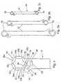
- Figs. 2a to 2cshow a set of dual-head wrenches 40 incorporating the head design illustrated in Fig. 1.
- wrenches in accordance with the present inventionmay be provided in a variety of sizes to suit standard workpiece sizes, with single or dual heads.
- a dual-head wrenchcould incorporate a first head in accordance with the invention and a second conventional head.
- Fig. 3billustrates a nut 42 engaging a bolt 44
- Fig. 3ashows the wrench of Fig. 1 engaging the nut 42. It is common for the nuts, bolt heads etc to become worn in use, so that the corners 46 of the nut between its peripheral faces wear flat as shown in Fig. 3b. The head of a conventional wrench will tend to slip around a worn nut of this type.
- the ringis being stretched from the position of the last segment 20f which is secured against the nut.
- the force transmitted around the ring 14also acts to deform the ring at the segment junctions 24a-e.
- the convex shape of inner surfaces 22 of the ring segments 20a-falso serve to enhance the grip between the ring 14 and the peripheral surfaces of the workpiece. Even if the workpiece is damaged, worn or undersized, providing there is sufficient initial contact and friction between the ring and the workpiece, the ring 14 will deform inwards to provide increased grip enabling further torque to be applied to rotate the workpiece.
- the junctions 24a-e between adjacent segments 20a-f of the ring 14provide "integral hinges", allowing the ring to deform elastically and close around the workpiece.
- the surfaces 34 and 36limit the deformation of the ring 14 when torque is applied in the direction of the arrow 48. However, if torque was applied in the opposite direction (arrow 50 in Fig. 1), there is a risk that the ring 14 would be damaged by being deformed plastically.
- Figs. 4a and 4billustrate a further embodiment of the invention which is similar to that of Fig. 1 except that the head 10 includes means for preventing the ring 14 from opening excessively if the head 10 is rotated in the direction indicated by the arrow 50.
- the free end 18 of the ring 14is provided with an outward projection 52 which co-operates with a corresponding recess 54 formed in the cam portion 26.
- the insert 32 of Fig. 1is omitted and the first cam surface 28 is formed integrally with the cam portion 26.
- Fig.5.illustrates a further embodiment similar to Fig. 1 and Fig. 2, with a different configuration of a catch arrangement to prevent opening of the ring.
- the free end 56 of the end segment 20f of the ring 14is extended and is accommodated by a notch or channel 58 formed in the head portion 10 adjacent the cam portion 26.
- the extended free end 56 and notch 58co-operate to limit movement of the end segment 20f of the ring 14 both in the direction of the arrow 48 and in the direction of the arrow 50.
- Other equivalent arrangementsmay be employed in these or any of the other embodiments of the invention to limit movement of the end segment 20f in either or both of the directions 48 and 50.
- Fig. 5again includes an insert 32 which provides the first cam surface 28 of the wrench. It will be understood that an insert of this type may be included in any of the embodiments of the invention, or the first cam surface 28 may be formed as an integral part of the head of the wrench in any of the embodiments of the invention.
- the head of the wrenchcomprises a substantially closed ring which, in use, substantially surrounds the workpiece.
- this arrangementmeans that, in certain circumstances, it may be difficult or impossible for the wrench to engage a particular workpiece.
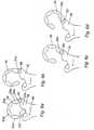
- Figs 6a-6dillustrate a further embodiment of the present invention in which the ring defined by the head of the wrench is provided with a hinge or pivot 60, enabling the ring 14 to be opened in order to engage a workpiece.
- the hinge 60is provided at the junction 24a between first and second segments adjacent the fixed end 16 of the ring 14.
- Fig. 6ashows the ring closed, in position for use.
- Figs. 6b, 6c and 6dillustrate the use of the hinge 60 to open the ring 14. This embodiment is particularly useful where the ring 14 of the wrench is to be fitted around, for example, a nut located on a length of pipe.
- the hinge 60allows the ring 14 to be opened out to allow it to be easily fitted around the workpiece.
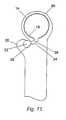
- Fig.7shows a wrench in accordance with the present invention similar to that of Figs 6 a-d, but with an integral first cam surface 28 rather than an insert.
- the convex inner surfaces 22 of the ring segments 20a-fhave less curvature than in the embodiment of Fig.1. This provides a larger surface area of contact between these surfaces and the surfaces of the workpiece.
- the junctions 24a-eare radiused so as to be substantially semicircular in profile.
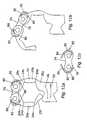
- Fig.8shows further embodiment of a wrench in accordance with present invention, similar to that of Figs 6 a-d, but with a hinge provided by ball and socket joint 62 which, in this example, is located between the second and third ring segments 20b,20c.
- Fig. 9shows a wrench in accordance with the present invention similar to that of Figs 6 a-d, with a knuckle joint 64 providing a hinge between the first and second ring segments 20a,20b..
- This embodimentis shown in its working position, where a torque is to be applied in the direction shown by arrow 48, such that the free end 18 of the ring 14 moves freely towards the abutment 34.
- the extent of this free movementis determined by a gap 66 formed by the knuckle joint between the adjacent ring segments 20a,20b. Once this gap 66 has been closed, any additional torque will cause the ring 14 to deform and the area inside the ring to decrease. The abutment of the segments 20a,20b provides additional leverage.
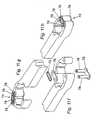
- Figs. 10a, 10b and 10cshow a wrench in accordance with the present invention similar to that of Figs 6 a-d, with an extended ball and socket joint 68 providing a hinge between the second and third ring segments 20b, 20c.
- This figurealso shows the extent to which the ring 14 may be opened to allow an object to be fitted inside the ring.
- the ring 14moves freely until an extension portion 71 of the ball and socket joint 68, connected to the third ring segment 20c, abuts against the outer surface of the second ring segment 20b. Thereafter, the area inside the ring is decreased by deformation of the ring about the junctions 24c-e between the segments 20c-f.
- Figs. 11a-eillustrate a further embodiment of the present invention in which the third and fourth ring segments 20c, 20d are hingeably connected by a chain link 74.
- chain linkas used herein means an arrangement in which a plate member 76 having a figure-of-eight configuration is disposed on either side of the ring 14 and pivot pins 78 extend between the plates 76 through bores formed at the ends of the adjacent ring segments 20c, 20d.
- Thisis a preferred form of hinge for use in accordance with the present invention and may be employed to interconnect one or more pairs of ring segments other than or in addition to the third and fourth segments as shown in this embodiment.
- Fig. 11ashows the wrench in its working position (closed) and Figs.
- FIG. 11b-eshow the ring 14 progressively opening from the working position.
- FIGs. 11f to 11hillustrate the chain link 74 in more detail.
- Fig. 11fis an exploded view of the chain link 74, also including a spring clip 79 which would normally be included in a chain link of this type.
- Fig. 11gshows the ring 14 hinged open and Fig. 11h shows the ring 14 hinged closed.
- Figs. 12a and 12bshow a further embodiment of the invention, similar to that of Figs. 11a-e, in which the chain link hinge 74 is provided with resilient bias means comprising spring elements 80 which tend to urge the ring 14 towards its normal closed, working position, illustrated in Fig. 12a.
- the combination of the hinge and resilient bias meansgenerally provides a junction between the adjacent ring sections connected by the hinge 74 (segments 20c,20d in this preferred example) which is more flexible than the "integral hinges" provided by the junctions 24a,b,d,e between the other pairs of adjacent segments.
- the use of such resilient bias meansthat the wrench operates in a substantially identical manner to that of the embodiment of Fig. 1 when rotated in the direction 48.
- the resilient bias means associated with the hinge 74allows the ring 14 to open slightly so that the ring 14 may rotate relative to the workpiece, thereby providing a type of ratchet mechanism so that the wrench does not need to be removed from the workpiece between successive strokes in the "working direction" 48.
- the bias meansallows the ring to rotate relative to the workpiece on the return stroke, and urges the ring segments back into their working position for the next working stroke.
- the spring elements 80are formed integrally with the plates 76 of the chain link 74, comprising resilient arms 82 which extend from either end of the plates 76, curving in the plane of the plates 76 around the outer ends thereof, and having end portions 84 which are bent out of the plane of the plates 76.
- the end portions 84 of the arms 82project into and engage with apertures 86 formed in the side faces of the adjacent ring segments 20c,20d.
- the ring 14may be opened against the return force of the spring elements 80 as seen in Fig. 12b, allowing the wrench to engage, for example, a nut located on a length of pipe, as in the previous embodiments of the invention incorporating hinged rings.
- Fig. 13shows a further embodiment of the present invention in which the inside surface of the ring 14 is substantially circular, rather than polygonal.
- the inner surface of the ring 14is provided with corrugations or serrations 90 which grip the workpiece inside the ring on application of a torque.
- the ring 14 as a wholeis sufficiently flexible to deform and close around the workpiece.
- the size, shape and distribution of the corrugations 90will depend on the nature of the intended workpiece.
- This embodimentmay also be modified to incorporate variations of the cam surfaces, stops and catches, hinges etc. described in relation to previous embodiments.
- the segmented rings of previous embodimentsmay be provided with serrations or corrugations on their inner surfaces.
Landscapes
- Engineering & Computer Science (AREA)
- Mechanical Engineering (AREA)
- Details Of Spanners, Wrenches, And Screw Drivers And Accessories (AREA)
- Valve-Gear Or Valve Arrangements (AREA)
- Devices For Conveying Motion By Means Of Endless Flexible Members (AREA)
- Valve Device For Special Equipments (AREA)
- Feeding Of Workpieces (AREA)
- Clamps And Clips (AREA)
- Measuring Volume Flow (AREA)
- Measuring Pulse, Heart Rate, Blood Pressure Or Blood Flow (AREA)
- External Artificial Organs (AREA)
Abstract
Description
As in the case of conventional wrenches, wrenches inaccordance with the present invention may be providedin a variety of sizes to suit standard workpiece sizes,with single or dual heads. A dual-head wrench could incorporate a first head in accordance with theinvention and a second conventional head.
Fig. 9 shows a wrench in accordance with the presentinvention similar to that of Figs 6 a-d, with a knucklejoint 64 providing a hinge between the first and
Claims (17)
- A wrench having a head portion (10) adapted to engage and applytorque to a workpiece (42) and turning means (12) for turning said headportion (10), said head portion (10) including a flexible ring portion (14)attached to said turning means (12) at one end and free at its other end, saidring portion (14) having an inner working surface for engaging the workpiece(42), and said turning means (12) including clamping means (32) forclamping the free end (36) of the ring portion (14) against the workpiecewhen the turning means (12) is turned in a predetermined direction (48),characterised in that a portion (18) of the flexible ring portion (14) at oradjacent the free end (36) thereof has an external, first cam surface (30) whichdefines a wedge shape with the inner working surface of said portion (18),said wedge shape being directed to increase in thickness towards the free end(36) of the flexible ring portion (14), and said clamping means (32) comprisesa second cam surface (28) arranged to cooperate with said wedge-shapedportion (18) so that when torque is applied to said head portion (10) in saidpredetermined direction (48), said wedge-shaped portion (18) is urged in sucha peripheral direction relative to the workpiece as to tend to close the flexiblering portion (14) around said workpiece (42).
- A wrench as claimed in claim 1, wherein said cam surface (28) isgenerally convex.
- A wrench as claimed in claim 1 or claim 2, wherein said outer surface(30) of said free end portion (14) is generally concave.
- A wrench as claimed in any preceding claim, wherein said cam surface(28) is formed integrally with said wrench.
- A wrench as claimed in any of claims 2 to 4, wherein said cam surface(28) is provided by an insert (32).
- A wrench as claimed in any preceding claim, wherein said ring member(14) comprises a plurality of segments (20a-f).
- A wrench as claimed in claim 6, wherein said segments (20a-f) define agenerally polygonal inner surface of said ring member (14).
- A wrench as claimed in claim 6 or claim 7, wherein each of saidsegments (20a-f) has an inner surface which is generally convex in thecircumferential direction of said ring member (14).
- A wrench as claimed in any one of claims 6 to 8, wherein at least someof said segments (20a-f) are formed integrally with one another and said ringmember (14) is adapted to deform resiliently at junctions (24a-e) betweenadjacent, integrally formed segments.
- A wrench as claimed in claim 9, wherein said junctions (24a-e) betweenadjacent, integrally formed rings have a reduced thickness in the radialdirection as compared with the remainder of said segments (20a-f).
- A wrench as claimed in claim 10, wherein said junctions (24a-e)comprise portions of the inner surface of said ring member which aregenerally concave in the circumferential direction of said ring member (14).
- A wrench as claimed in any preceding claim, wherein the inner surfaceof said ring member is corrugated.
- A wrench as claimed in any preceding claim, wherein said head portion(10) includes means for limiting movement of said portion (18) of said ringmember (14) relative to said fixed end (16) thereof in said predetermineddirection (48).
- A wrench as claimed in any preceding claim, wherein said head portion(10) includes means for limiting movement of said portion (18) of said ringmember (14) relative to said fixed end (16) thereof in a direction (50) oppositeto said predetermined direction (48).
- A wrench as claimed in any preceding claim, wherein said head portion(10) includes hinge means (60,62,64,68,72,74) whereby at least a portion ofsaid ring member (14) may be pivoted in the plane of said ring member (14)relative to the remainder of said head portion (10).
- A wrench as claimed in claim 15, wherein said ring member comprisesa plurality of segments (20a-f) and wherein said hinge means(60,62,64,68,72,74) is located between at least one pair of adjacent segments(20a-f).
- A wrench as claimed in claim 14 or claim 15, including resilient biasmeans (80) associated with said hinge means (60,62,64,68,72,74) and adaptedto bias said ring member towards a closed position.
Applications Claiming Priority (3)
| Application Number | Priority Date | Filing Date | Title |
|---|---|---|---|
| GB9907059 | 1999-03-29 | ||
| GBGB9907059.1AGB9907059D0 (en) | 1999-03-29 | 1999-03-29 | Smart spanner |
| PCT/GB2000/001204WO2000058057A1 (en) | 1999-03-29 | 2000-03-29 | Wrench |
Publications (2)
| Publication Number | Publication Date |
|---|---|
| EP1165291A1 EP1165291A1 (en) | 2002-01-02 |
| EP1165291B1true EP1165291B1 (en) | 2004-05-12 |
Family
ID=10850467
Family Applications (1)
| Application Number | Title | Priority Date | Filing Date |
|---|---|---|---|
| EP00918988AExpired - LifetimeEP1165291B1 (en) | 1999-03-29 | 2000-03-29 | Wrench |
Country Status (10)
| Country | Link |
|---|---|
| US (1) | US6978701B1 (en) |
| EP (1) | EP1165291B1 (en) |
| JP (1) | JP2002539963A (en) |
| CN (1) | CN1247364C (en) |
| AT (1) | ATE266501T1 (en) |
| AU (1) | AU3975200A (en) |
| DE (1) | DE60010681T2 (en) |
| ES (1) | ES2220450T3 (en) |
| GB (2) | GB9907059D0 (en) |
| WO (1) | WO2000058057A1 (en) |
Families Citing this family (37)
| Publication number | Priority date | Publication date | Assignee | Title |
|---|---|---|---|---|
| IE20010943A1 (en)* | 2001-10-26 | 2003-04-30 | Seamus Duffy | A Fold-away Wrench Set, Comprising of Two Wrench Headsets for Applying Torque to Known Bits and Fasteners |
| IE20010953A1 (en)* | 2001-10-30 | 2003-04-30 | Seamus Duffy | Clamp Drive Socket Bar |
| GB0218339D0 (en)* | 2002-08-08 | 2002-09-18 | Smart Tools Ltd | Torque tightening wrench |
| CN100562406C (en)* | 2004-08-13 | 2009-11-25 | 钻岩气动有限公司 | Hand vice |
| GB0721222D0 (en)* | 2007-10-29 | 2007-12-05 | Buchanan Nigel A | Wrench |
| GB0814014D0 (en) | 2008-07-31 | 2008-09-10 | Buchanan Nigel A | Line wrenches |
| US7913589B2 (en)* | 2008-11-17 | 2011-03-29 | Chen-Tsung Chen | Adjustable wrench that clamps a workpiece exactly and tightly |
| EP2601016A2 (en)* | 2010-08-06 | 2013-06-12 | American Grease Stick Company | Wrench with trigger |
| DE102012200644A1 (en) | 2012-01-18 | 2013-07-18 | Hilti Aktiengesellschaft | wrench |
| US9021923B2 (en)* | 2012-10-23 | 2015-05-05 | Unison Industries, Llc | Torque wrench adaptor tool assembly and methods of operating the same |
| US9205539B2 (en) | 2013-04-01 | 2015-12-08 | Emerson Electric Co. | Wrench |
| USD717619S1 (en) | 2013-04-01 | 2014-11-18 | Ridge Tool Company | Tool handle |
| USD739192S1 (en) | 2013-04-01 | 2015-09-22 | Ridge Tool Company | Insert for tool |
| USD742707S1 (en) | 2013-04-01 | 2015-11-10 | Ridge Tool Company | Tool head |
| US9434055B2 (en) | 2013-04-01 | 2016-09-06 | Ridge Tool Company | Replaceable gripping inserts for wrenches |
| USD749924S1 (en) | 2014-08-29 | 2016-02-23 | Ridge Tool Company | Wrench |
| USD748958S1 (en) | 2014-08-29 | 2016-02-09 | Ridge Tool Company | Wrench |
| USD750944S1 (en) | 2014-08-29 | 2016-03-08 | Ridge Tool Company | Wrench |
| DE102014225916B4 (en)* | 2014-12-15 | 2016-07-14 | NUBIUS GROUP Präzisionswerkzeuge GmbH | Key with conical surface |
| TW201714713A (en)* | 2015-10-20 | 2017-05-01 | yu-xiang Huang | Clamp body structure whereby screw members of different specifications or tubes of different diameters can be clamped between the third body and the first body |
| DE202016100497U1 (en) | 2016-02-01 | 2016-02-15 | Chun-Wei Yang | pipe wrench |
| GB201704196D0 (en) | 2017-03-16 | 2017-05-03 | Buchanan Nigel Alexander | Low profile line wrench |
| CA3069334A1 (en)* | 2017-07-11 | 2019-01-17 | Integrity Engineering Solutions Pty Ltd | Backup wrenches |
| CN112008639B (en)* | 2019-05-31 | 2021-11-19 | 胡厚飞 | Fast reciprocating operation wrench |
| TWI704034B (en) | 2019-05-31 | 2020-09-11 | 胡厚飛 | Wrench for fast reciprocating operation |
| TWI695758B (en) | 2019-06-28 | 2020-06-11 | 胡厚飛 | Wrench for reciprocating operation of connecting fasteners |
| US11247311B2 (en) | 2019-10-22 | 2022-02-15 | The Boeing Company | Wrench head |
| US11224958B2 (en) | 2019-10-22 | 2022-01-18 | The Boeing Company | Wrench head |
| US11229992B2 (en) | 2019-10-22 | 2022-01-25 | The Boeing Company | Wrench head |
| US11318588B2 (en) | 2019-10-22 | 2022-05-03 | The Boeing Company | Wrench head |
| US11235442B2 (en) | 2019-10-22 | 2022-02-01 | The Boeing Company | Wrench head |
| US11235440B2 (en) | 2019-10-22 | 2022-02-01 | The Boeing Company | Wrench head |
| US11351662B2 (en) | 2019-10-22 | 2022-06-07 | The Boeing Company | Wrench head |
| US11267106B2 (en) | 2019-10-22 | 2022-03-08 | The Boeing Company | Wrench head |
| US11267108B2 (en) | 2019-10-22 | 2022-03-08 | The Boeing Company | Wrench head |
| GB202110518D0 (en) | 2021-07-21 | 2021-09-01 | Buchanan Nigel | Ratcheting 3 Jaw Wrench |
| GB202110473D0 (en) | 2021-07-21 | 2021-09-01 | Buchanan Nigel | Push on pull off wrench |
Family Cites Families (16)
| Publication number | Priority date | Publication date | Assignee | Title |
|---|---|---|---|---|
| US1051562A (en)* | 1911-09-19 | 1913-01-28 | Firm Of C H Winterhoff | Wrench. |
| US1177620A (en)* | 1915-08-09 | 1916-04-04 | Hardin L Hardeman | Pipe-wrench. |
| US1464128A (en) | 1922-02-24 | 1923-08-07 | Coes Wrench Company | Nut wrench |
| US1584861A (en)* | 1924-03-18 | 1926-05-18 | Homer A Jones | Flexible wrench |
| US1666353A (en) | 1924-07-14 | 1928-04-17 | Adolph C Schelf | Wrench |
| GB235434A (en) | 1924-09-11 | 1925-06-18 | Karl Ridel | Improvements in tongs for gripping pipes or other round articles |
| US1610387A (en)* | 1925-02-25 | 1926-12-14 | James E Pennington | Wrench |
| US1569148A (en)* | 1925-05-01 | 1926-01-12 | Donald M Stainbrook | Pipe wrench |
| US2436329A (en) | 1942-03-24 | 1948-02-17 | Westinghouse Electric Corp | Phenol formaldehyde resin-glycinin protein emulsion |
| US2426498A (en)* | 1943-10-22 | 1947-08-26 | Republic Aviat Corp | Clamp structure |
| US2435329A (en)* | 1944-12-09 | 1948-02-03 | Don M Stainbrook | Pipe wrench |
| US2457223A (en)* | 1945-11-06 | 1948-12-28 | Clyde H Green | Pivoted outer jaw pipe wrench |
| DE1603767A1 (en) | 1967-11-09 | 1971-02-18 | Daimler Benz Ag | Ring spanner |
| US4145938A (en)* | 1977-10-11 | 1979-03-27 | Laird Jr Jonathan L | Strap wrench |
| US4967612A (en)* | 1989-10-13 | 1990-11-06 | Russell Sparling | Flare nut wrench |
| US6431032B1 (en)* | 2000-12-15 | 2002-08-13 | Armen Kuryan | Alex wrench |
- 1999
- 1999-03-29GBGBGB9907059.1Apatent/GB9907059D0/ennot_activeCeased
- 2000
- 2000-03-29DEDE60010681Tpatent/DE60010681T2/ennot_activeExpired - Lifetime
- 2000-03-29EPEP00918988Apatent/EP1165291B1/ennot_activeExpired - Lifetime
- 2000-03-29AUAU39752/00Apatent/AU3975200A/ennot_activeAbandoned
- 2000-03-29WOPCT/GB2000/001204patent/WO2000058057A1/enactiveIP Right Grant
- 2000-03-29GBGB0123981Apatent/GB2363588B/ennot_activeExpired - Fee Related
- 2000-03-29USUS09/937,767patent/US6978701B1/ennot_activeExpired - Lifetime
- 2000-03-29ESES00918988Tpatent/ES2220450T3/ennot_activeExpired - Lifetime
- 2000-03-29JPJP2000607794Apatent/JP2002539963A/enactivePending
- 2000-03-29ATAT00918988Tpatent/ATE266501T1/ennot_activeIP Right Cessation
- 2000-03-29CNCN00807685.5Apatent/CN1247364C/ennot_activeExpired - Fee Related
Also Published As
| Publication number | Publication date |
|---|---|
| US6978701B1 (en) | 2005-12-27 |
| CN1351533A (en) | 2002-05-29 |
| ES2220450T3 (en) | 2004-12-16 |
| CN1247364C (en) | 2006-03-29 |
| GB2363588B (en) | 2003-07-30 |
| AU3975200A (en) | 2000-10-16 |
| DE60010681T2 (en) | 2005-05-19 |
| GB0123981D0 (en) | 2001-11-28 |
| JP2002539963A (en) | 2002-11-26 |
| DE60010681D1 (en) | 2004-06-17 |
| EP1165291A1 (en) | 2002-01-02 |
| ATE266501T1 (en) | 2004-05-15 |
| GB2363588A (en) | 2002-01-02 |
| WO2000058057A1 (en) | 2000-10-05 |
| GB9907059D0 (en) | 1999-05-19 |
Similar Documents
| Publication | Publication Date | Title |
|---|---|---|
| EP1165291B1 (en) | Wrench | |
| EP3595845B1 (en) | Line wrench heads and line wrenches | |
| US6904833B2 (en) | Asymmetric wrench and fastener system | |
| US20080276762A1 (en) | Torque transmission mechanism | |
| US5092203A (en) | Wrench openings | |
| US8677864B1 (en) | Compact cam actuated adjustable socket | |
| US7418890B2 (en) | Wrench with split ring | |
| US5456143A (en) | Open end ratchet wrench | |
| US20020139226A1 (en) | Articulated wrench | |
| US7201086B2 (en) | Wrench with articulating head | |
| CA2234179C (en) | Rotary wrenching tool | |
| EP1603710A1 (en) | Wrench socket | |
| US20040237731A1 (en) | Adjustable wrench | |
| GB2382319A (en) | A resiliently clamping wrench | |
| JP3223283U (en) | wrench | |
| CA2641825C (en) | Wrenches | |
| KR100373422B1 (en) | A wrench | |
| KR20040003872A (en) | A screw coupler and screw driver for the same |
Legal Events
| Date | Code | Title | Description |
|---|---|---|---|
| PUAI | Public reference made under article 153(3) epc to a published international application that has entered the european phase | Free format text:ORIGINAL CODE: 0009012 | |
| 17P | Request for examination filed | Effective date:20011024 | |
| AK | Designated contracting states | Kind code of ref document:A1 Designated state(s):AT BE CH CY DE DK ES FI FR GB GR IE IT LI LU MC NL PT SE | |
| RAP1 | Party data changed (applicant data changed or rights of an application transferred) | Owner name:SMART TOOLS LIMITED | |
| 17Q | First examination report despatched | Effective date:20020128 | |
| RAP3 | Party data changed (applicant data changed or rights of an application transferred) | Owner name:SMART TOOLS LIMITED | |
| GRAP | Despatch of communication of intention to grant a patent | Free format text:ORIGINAL CODE: EPIDOSNIGR1 | |
| GRAS | Grant fee paid | Free format text:ORIGINAL CODE: EPIDOSNIGR3 | |
| GRAA | (expected) grant | Free format text:ORIGINAL CODE: 0009210 | |
| AK | Designated contracting states | Kind code of ref document:B1 Designated state(s):AT BE CH CY DE DK ES FI FR GB GR IE IT LI LU MC NL PT SE | |
| PG25 | Lapsed in a contracting state [announced via postgrant information from national office to epo] | Ref country code:CH Free format text:LAPSE BECAUSE OF FAILURE TO SUBMIT A TRANSLATION OF THE DESCRIPTION OR TO PAY THE FEE WITHIN THE PRESCRIBED TIME-LIMIT Effective date:20040512 Ref country code:NL Free format text:LAPSE BECAUSE OF FAILURE TO SUBMIT A TRANSLATION OF THE DESCRIPTION OR TO PAY THE FEE WITHIN THE PRESCRIBED TIME-LIMIT Effective date:20040512 Ref country code:LI Free format text:LAPSE BECAUSE OF FAILURE TO SUBMIT A TRANSLATION OF THE DESCRIPTION OR TO PAY THE FEE WITHIN THE PRESCRIBED TIME-LIMIT Effective date:20040512 Ref country code:FI Free format text:LAPSE BECAUSE OF FAILURE TO SUBMIT A TRANSLATION OF THE DESCRIPTION OR TO PAY THE FEE WITHIN THE PRESCRIBED TIME-LIMIT Effective date:20040512 Ref country code:BE Free format text:LAPSE BECAUSE OF FAILURE TO SUBMIT A TRANSLATION OF THE DESCRIPTION OR TO PAY THE FEE WITHIN THE PRESCRIBED TIME-LIMIT Effective date:20040512 Ref country code:AT Free format text:LAPSE BECAUSE OF FAILURE TO SUBMIT A TRANSLATION OF THE DESCRIPTION OR TO PAY THE FEE WITHIN THE PRESCRIBED TIME-LIMIT Effective date:20040512 | |
| REG | Reference to a national code | Ref country code:GB Ref legal event code:FG4D | |
| REG | Reference to a national code | Ref country code:CH Ref legal event code:EP | |
| REG | Reference to a national code | Ref country code:IE Ref legal event code:FG4D | |
| REF | Corresponds to: | Ref document number:60010681 Country of ref document:DE Date of ref document:20040617 Kind code of ref document:P | |
| PG25 | Lapsed in a contracting state [announced via postgrant information from national office to epo] | Ref country code:GR Free format text:LAPSE BECAUSE OF FAILURE TO SUBMIT A TRANSLATION OF THE DESCRIPTION OR TO PAY THE FEE WITHIN THE PRESCRIBED TIME-LIMIT Effective date:20040812 Ref country code:SE Free format text:LAPSE BECAUSE OF FAILURE TO SUBMIT A TRANSLATION OF THE DESCRIPTION OR TO PAY THE FEE WITHIN THE PRESCRIBED TIME-LIMIT Effective date:20040812 Ref country code:DK Free format text:LAPSE BECAUSE OF FAILURE TO SUBMIT A TRANSLATION OF THE DESCRIPTION OR TO PAY THE FEE WITHIN THE PRESCRIBED TIME-LIMIT Effective date:20040812 | |
| NLV1 | Nl: lapsed or annulled due to failure to fulfill the requirements of art. 29p and 29m of the patents act | ||
| REG | Reference to a national code | Ref country code:CH Ref legal event code:PL | |
| REG | Reference to a national code | Ref country code:ES Ref legal event code:FG2A Ref document number:2220450 Country of ref document:ES Kind code of ref document:T3 | |
| ET | Fr: translation filed | ||
| PLBE | No opposition filed within time limit | Free format text:ORIGINAL CODE: 0009261 | |
| STAA | Information on the status of an ep patent application or granted ep patent | Free format text:STATUS: NO OPPOSITION FILED WITHIN TIME LIMIT | |
| PG25 | Lapsed in a contracting state [announced via postgrant information from national office to epo] | Ref country code:LU Free format text:LAPSE BECAUSE OF NON-PAYMENT OF DUE FEES Effective date:20050329 Ref country code:CY Free format text:LAPSE BECAUSE OF FAILURE TO SUBMIT A TRANSLATION OF THE DESCRIPTION OR TO PAY THE FEE WITHIN THE PRESCRIBED TIME-LIMIT Effective date:20050329 Ref country code:IE Free format text:LAPSE BECAUSE OF NON-PAYMENT OF DUE FEES Effective date:20050329 | |
| PG25 | Lapsed in a contracting state [announced via postgrant information from national office to epo] | Ref country code:MC Free format text:LAPSE BECAUSE OF NON-PAYMENT OF DUE FEES Effective date:20050331 | |
| 26N | No opposition filed | Effective date:20050215 | |
| REG | Reference to a national code | Ref country code:IE Ref legal event code:MM4A | |
| REG | Reference to a national code | Ref country code:GB Ref legal event code:732E | |
| REG | Reference to a national code | Ref country code:FR Ref legal event code:TP | |
| PG25 | Lapsed in a contracting state [announced via postgrant information from national office to epo] | Ref country code:PT Free format text:LAPSE BECAUSE OF NON-PAYMENT OF DUE FEES Effective date:20041012 | |
| REG | Reference to a national code | Ref country code:ES Ref legal event code:PC2A | |
| PGFP | Annual fee paid to national office [announced via postgrant information from national office to epo] | Ref country code:ES Payment date:20140324 Year of fee payment:15 | |
| PGFP | Annual fee paid to national office [announced via postgrant information from national office to epo] | Ref country code:IT Payment date:20140331 Year of fee payment:15 Ref country code:FR Payment date:20140331 Year of fee payment:15 | |
| PG25 | Lapsed in a contracting state [announced via postgrant information from national office to epo] | Ref country code:IT Free format text:LAPSE BECAUSE OF NON-PAYMENT OF DUE FEES Effective date:20150329 | |
| REG | Reference to a national code | Ref country code:FR Ref legal event code:ST Effective date:20151130 | |
| PG25 | Lapsed in a contracting state [announced via postgrant information from national office to epo] | Ref country code:FR Free format text:LAPSE BECAUSE OF NON-PAYMENT OF DUE FEES Effective date:20150331 | |
| REG | Reference to a national code | Ref country code:ES Ref legal event code:FD2A Effective date:20160428 | |
| PG25 | Lapsed in a contracting state [announced via postgrant information from national office to epo] | Ref country code:ES Free format text:LAPSE BECAUSE OF NON-PAYMENT OF DUE FEES Effective date:20150330 | |
| REG | Reference to a national code | Ref country code:GB Ref legal event code:732E Free format text:REGISTERED BETWEEN 20170305 AND 20170308 | |
| REG | Reference to a national code | Ref country code:DE Ref legal event code:R081 Ref document number:60010681 Country of ref document:DE Owner name:STENTIFORD, NEIL, NOTTINGHAM, GB Free format text:FORMER OWNER: SMC CORP..LTD., NOTTINHAM, NOTTINGHAMSHIRE, GB Ref country code:DE Ref legal event code:R082 Ref document number:60010681 Country of ref document:DE Representative=s name:MAMMEL UND MASER, PATENTANWAELTE, DE | |
| PGFP | Annual fee paid to national office [announced via postgrant information from national office to epo] | Ref country code:GB Payment date:20170316 Year of fee payment:18 | |
| PGFP | Annual fee paid to national office [announced via postgrant information from national office to epo] | Ref country code:DE Payment date:20170609 Year of fee payment:18 | |
| REG | Reference to a national code | Ref country code:DE Ref legal event code:R119 Ref document number:60010681 Country of ref document:DE | |
| GBPC | Gb: european patent ceased through non-payment of renewal fee | Effective date:20180329 | |
| PG25 | Lapsed in a contracting state [announced via postgrant information from national office to epo] | Ref country code:DE Free format text:LAPSE BECAUSE OF NON-PAYMENT OF DUE FEES Effective date:20181002 | |
| PG25 | Lapsed in a contracting state [announced via postgrant information from national office to epo] | Ref country code:GB Free format text:LAPSE BECAUSE OF NON-PAYMENT OF DUE FEES Effective date:20180329 |