EP1163879A2 - Lancing mechanism - Google Patents
Lancing mechanismDownload PDFInfo
- Publication number
- EP1163879A2 EP1163879A2EP01112875AEP01112875AEP1163879A2EP 1163879 A2EP1163879 A2EP 1163879A2EP 01112875 AEP01112875 AEP 01112875AEP 01112875 AEP01112875 AEP 01112875AEP 1163879 A2EP1163879 A2EP 1163879A2
- Authority
- EP
- European Patent Office
- Prior art keywords
- lance
- forcing plunger
- linkage
- lancing mechanism
- forcing
- Prior art date
- Legal status (The legal status is an assumption and is not a legal conclusion. Google has not performed a legal analysis and makes no representation as to the accuracy of the status listed.)
- Granted
Links
Images


Classifications
- A—HUMAN NECESSITIES
- A61—MEDICAL OR VETERINARY SCIENCE; HYGIENE
- A61B—DIAGNOSIS; SURGERY; IDENTIFICATION
- A61B5/00—Measuring for diagnostic purposes; Identification of persons
- A61B5/15—Devices for taking samples of blood
- A61B5/151—Devices specially adapted for taking samples of capillary blood, e.g. by lancets, needles or blades
- A61B5/15186—Devices loaded with a single lancet, i.e. a single lancet with or without a casing is loaded into a reusable drive device and then discarded after use; drive devices reloadable for multiple use
- A61B5/15188—Constructional features of reusable driving devices
- A61B5/15192—Constructional features of reusable driving devices comprising driving means, e.g. a spring, for retracting the lancet unit into the driving device housing
- A61B5/15194—Constructional features of reusable driving devices comprising driving means, e.g. a spring, for retracting the lancet unit into the driving device housing fully automatically retracted, i.e. the retraction does not require a deliberate action by the user, e.g. by terminating the contact with the patient's skin
- A—HUMAN NECESSITIES
- A61—MEDICAL OR VETERINARY SCIENCE; HYGIENE
- A61B—DIAGNOSIS; SURGERY; IDENTIFICATION
- A61B5/00—Measuring for diagnostic purposes; Identification of persons
- A61B5/15—Devices for taking samples of blood
- A61B5/150007—Details
- A61B5/150015—Source of blood
- A61B5/150022—Source of blood for capillary blood or interstitial fluid
- A—HUMAN NECESSITIES
- A61—MEDICAL OR VETERINARY SCIENCE; HYGIENE
- A61B—DIAGNOSIS; SURGERY; IDENTIFICATION
- A61B5/00—Measuring for diagnostic purposes; Identification of persons
- A61B5/15—Devices for taking samples of blood
- A61B5/150007—Details
- A61B5/150374—Details of piercing elements or protective means for preventing accidental injuries by such piercing elements
- A61B5/150381—Design of piercing elements
- A61B5/150412—Pointed piercing elements, e.g. needles, lancets for piercing the skin
- A—HUMAN NECESSITIES
- A61—MEDICAL OR VETERINARY SCIENCE; HYGIENE
- A61B—DIAGNOSIS; SURGERY; IDENTIFICATION
- A61B5/00—Measuring for diagnostic purposes; Identification of persons
- A61B5/15—Devices for taking samples of blood
- A61B5/151—Devices specially adapted for taking samples of capillary blood, e.g. by lancets, needles or blades
- A61B5/15101—Details
- A61B5/15103—Piercing procedure
- A61B5/15107—Piercing being assisted by a triggering mechanism
- A61B5/15113—Manually triggered, i.e. the triggering requires a deliberate action by the user such as pressing a drive button
- A—HUMAN NECESSITIES
- A61—MEDICAL OR VETERINARY SCIENCE; HYGIENE
- A61B—DIAGNOSIS; SURGERY; IDENTIFICATION
- A61B5/00—Measuring for diagnostic purposes; Identification of persons
- A61B5/15—Devices for taking samples of blood
- A61B5/151—Devices specially adapted for taking samples of capillary blood, e.g. by lancets, needles or blades
- A61B5/15101—Details
- A61B5/15115—Driving means for propelling the piercing element to pierce the skin, e.g. comprising mechanisms based on shape memory alloys, magnetism, solenoids, piezoelectric effect, biased elements, resilient elements, vacuum or compressed fluids
- A61B5/15117—Driving means for propelling the piercing element to pierce the skin, e.g. comprising mechanisms based on shape memory alloys, magnetism, solenoids, piezoelectric effect, biased elements, resilient elements, vacuum or compressed fluids comprising biased elements, resilient elements or a spring, e.g. a helical spring, leaf spring, or elastic strap
- A—HUMAN NECESSITIES
- A61—MEDICAL OR VETERINARY SCIENCE; HYGIENE
- A61B—DIAGNOSIS; SURGERY; IDENTIFICATION
- A61B5/00—Measuring for diagnostic purposes; Identification of persons
- A61B5/15—Devices for taking samples of blood
- A61B5/151—Devices specially adapted for taking samples of capillary blood, e.g. by lancets, needles or blades
- A61B5/15101—Details
- A61B5/15126—Means for controlling the lancing movement, e.g. 2D- or 3D-shaped elements, tooth-shaped elements or sliding guides
- A61B5/15128—Means for controlling the lancing movement, e.g. 2D- or 3D-shaped elements, tooth-shaped elements or sliding guides comprising 2D- or 3D-shaped elements, e.g. cams, curved guide rails or threads
Definitions
- the present inventionrelates generally to blood monitoring devices, and, more particularly, to a lancing mechanism for lancing a user's skin to obtain a sample of blood for analysis.
- the obtaining of bloodis as painless as possible.
- One example of a need for painlessly obtaining a sample of bloodis in connection with a blood glucose monitoring system where a user must frequently use the system to monitor the user's blood glucose level.
- Those who have irregular blood glucose concentration levelsare medically required to regularly self-monitor their blood glucose concentration level.
- An irregular blood glucose levelcan be brought on by a variety of reasons including illness such as diabetes.
- the purpose of monitoring the blood glucose concentration levelis to determine the blood glucose concentration level and then to take corrective action, based upon whether the level is too high or too low, to bring the level back within a normal range.
- the failure to take corrective actioncan have serious implications.
- blood glucose levels drop too low -known as hypoglycemia -
- a personcan become nervous, shaky, and confused. That person's judgment may become impaired and that person may eventually pass out.
- a personcan also become very ill if their blood glucose level becomes too high - a condition known as hyperglycemia. Both conditions, hypoglycemia and hyperglycemia, are both potentially life-threatening emergencies.
- One method of monitoring a person's blood glucose levelis with a portable, hand-held blood glucose testing device.
- the portable nature of these devicesenables the users to conveniently test their blood glucose levels wherever the user may be.
- a drop of bloodis obtained from the fingertip using a separate lancing device.
- the lancing devicecontains a needle lance to puncture the skin.
- the bloodis harvested using the blood glucose testing device.
- the bloodis drawn inside of the testing device which then determines the concentration of glucose in the blood.
- the results of the testare communicated to the user via a display on the testing device.
- An insufficient lancingcan result in an erroneous analysis if the user does not recognize that the lancing has not produced the requisite volume of blood for analysis. Or, if the user does recognize an insufficient lancing has occurred, the user must re-lance resulting in another laceration in the user's skin and more pain. The user may eventually have to replace the lance which has degraded over time.
- a lancing mechanism for puncturing skincomprises a lance having a penetration end which is adapted to puncture skin.
- the penetration end of the lanceis movable from a first position to a second position during a forward stroke and between the second position and the first position during a return stroke.
- a forcing plungerapplies a force to the lance to move the lance from the first position to the second during the forward stroke.
- the forcing plungeris adapted to engage the lance during the forward stroke to move the penetration end of the lance from the first position to the second position and to disengage the lance when the penetration end of the lance approaches the second position.
- a first resilient member coupled to the lancemoves the first end of the lance from the second position to the first position during the return stroke.
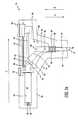
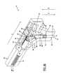
- the lancing mechanism 10includes a lance 12 disposed within a housing 14.
- the lance 12has a sharp penetration end 16 which is capable of puncturing skin to obtain of drop of blood for analysis.
- the penetration end 16 of the lance 12extends beyond the housing 14 through an aperture 18 disposed in the housing 14 to puncture a user's skin. After making the initial laceration in the user's skin, the lance 12 is drawn back within the housing 14.
- the lancing mechanism 10is designed to fire the lance 12 without experiencing the aforementioned oscillations associated with prior art lancing devices. During a forward stroke, the penetration end 16 of the lance 12 is moved to its penetration depth while engaged by a forcing plunger 20 via a linkage 22. Once the penetration end 16 of the lance has reached its penetration depth, the lance 12 beings its return stroke wherein a first compression spring 24 causes the lance 12 to ascend back into the bounds of the housing 14.
- the forcing plunger 20provides the force necessary to move the penetration end 16 of the lance 12 through a user's skin to the penetration depth.
- the forcing plunger 20transmits the force provided to it by a second compression spring 26 through the linkage 22 to the lance 12.
- the forcing plunger 20is drawn back to the pre-firing position with a slider 28 thus compressing the second compression spring 26.
- the forcing plunger 20is held in place by a trigger 30. When depressed, the trigger 30 releases the forcing plunger 20 thus firing the lancing mechanism 10.
- the lancing device 10 of the present inventionremedies the aforementioned problems associated with prior art lancing devices by moving the lance 12 a known length during a forward stoke with a linkage 22.
- the penetration depth of the lanceis not based on a spring constant and the extension of that spring past the static length of the spring.
- the lance 12which is positioned in the housing in a pre-firing position (FIG. 1a) is movable in the direction indicated by arrow A during the forward stroke and in the direction indicated by arrow B during the return stroke.
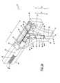
- the housing 14contains a first channel 32 which constrains the lateral movement of the lance 12.
- the first channel 32is substantially parallel to a longitudinal axis of the lance 12.
- the lance 12has a base 34 which travels along with the lance 12 in a second channel 36.
- the first compression spring 24is disposed in the second channel 36 between the base 34 and a shelf 38 formed at the intersection of the second channel 36 and the first channel 32.
- the base 34contains an outwardly extending tab 40 which mates with a corresponding linear slot 41 (FIG. 3a) disposed within the housing 14. The tab 40 and the corresponding linear slot 41 maintain the linear alignment of the base 34.
- the housing 14contains a third channel 42 which constrains the lateral movement of the forcing plunger 20.
- the third channel 42is substantially parallel to a longitudinal axis of the forcing plunger 20.
- the forcing plunger 20is disposed within the housing 14 substantially perpendicular to the lance 12.
- the second compression spring 26is disposed between a base 44 of the forcing plunger 20 and the a base 46 of the third channel 42.
- the forcing plunger 20moves in the direction indicated by the arrow C from a pre-firing position (FIG. 1a) to a post-firing position (FIG. 3a). The movement of the forcing plunger 20 from the pre-firing position to the post-firing position coincides with the forward and return stroke of the lance 12.
- the forcing plunger 20has a rounded end 48 which contains outwardly extending tabs 50 which mate with corresponding slots 52 disposed in the housing 14.
- the combination of the outwardly extending tabs 50 and the corresponding slots 52aide in maintaining the linear movement of the forcing plunger 20 when advancing from the pre-firing position to the post-firing position.
- the housing 14contains an hollow portion 54 to accommodate the rotation of the linkage 22 during the operation of the lancing mechanism.
- the linkage 22is pivotally coupled to the base 34 via a pin 56.
- the linkage 22has a curved receiving end 58 which is designed to engage the rounded end 48 of the forcing plunger 20.
- FIGS. 1a and 1bIn order to lance a user's skin, a user holds the lancing mechanism 10 by a handle portion 60 of the housing 14 in a manner such that the portion of the housing 14 containing the aperture 18 is pressed against the user's skin.
- the forcing plunger 20In FIGS. 1a and 1b, the forcing plunger 20 is shown in the pre-firing position. The user depresses the trigger 30 of the lancing mechanism 10 to release the forcing plunger 20. Upon being released, the forcing plunger 20 rapidly accelerates in the direction indicated of the arrow C. In the pre-firing position, the rounded end 48 of the forcing plunger 20 is substantially in contact with the curved receiving end 58 of the linkage 22.
- the curved receiving end 58contains a lip 62 which maintains the contact between the curved receiving end 58 of the linkage 22 and the rounded end 48 of the forcing plunger 20.
- the linear movement of the plunger 20 in the direction of the arrow Cforces the linkage 22 to move linearly in the direction of arrow A and to rotate in the clockwise direction. In turn, the aforementioned movement of the linkage 22 forces the lance 12 linearly downward in the direction of the arrow A.
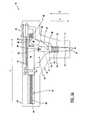
- depression of the trigger 30fires the forcing plunger 20.
- the forcing plunger 20rapidly advances from the pre-firing position in the direction of arrow C.
- the forcing plunger 20engages the linkage 22 which intern propels the lance 12 downward in the direction of arrow A.
- the linkage 22has rotated in the clockwise position such that it is shown in approximately the twelve o'clock position.
- the linkage 22has also been moved downward by the forcing plunger 20 a distance sufficient for the lance 12 to extend beyond the housing a distance X about equivalent to the penetration depth.
- the forward stroke of the lance 12concludes when the distance X is at a maximum.
- the forcing plunger 20continues to move in the direction of the arrow C which in turn further rotates the linkage 22 in the clockwise direction.
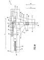
- the first compression spring 24forces the lance 12 and the linkage 22 upward to the position shown in FIGS. 3a and 3b. No oscillation of the lance 12 occurs because the first compression spring 24 is prohibited from extending to its static length.
- the outwardly extending tab 40 on the base 34 of the lance 12engages an upper end 68 of the slot 41 to prevent any further movement of the lance in the direction of the arrow B.
- a firing of the lancing mechanism 10results in only one forward and one return stroke of the lance 12.
- the lancing mechanism 10eliminates the multiple oscillations of the lance into and out of the laceration created in the user's skin which is a problem associated with some prior art lancing devices. This problem is remedied because the length of the forward stroke of the lance 12 of the lancing mechanism 10 is not dependant on the spring constant of a spring which moves a prior art lance and the extension of that spring past its static length.
- the forward stroke of the lance 12is dependant on the length of the linkage 22. Accordingly, in various embodiments of the present invention, the length of the linkage 22 is varied in order to change the penetration depth of the lancing device 12.
- the penetration depth of the lancing mechanism 10remains consistent over the life of the lancing mechanism 10 because the penetration depth is dependant on the length of the linkage 22. Conversely, the penetration depth of a prior art lance tends to degrade over time because the mechanical properties of the spring which moves the lance tend to degrade over time. Any oscillations of the lance 12 due to the first compression spring 24 are suppressed and do not cause repeated lancings because the combination of the tab 40 and the slot 41 prohibit the spring 24 form extending past its static length.
- the lancing mechanism 10is shown with the slider 28 drawing the forcing plunger 20 from the post-firing position (FIG. 3a) to the pre-firing position (FIG. 1a).
- the slider 28,which is biased in the far right position by a third compression spring 70 as shown in FIG. 3a, is used to move the lancing mechanism 10 back into the pre-firing position.
- the usersimply slides the slider 28 to the left as viewed in FIG. 4a to ready the lancing mechanism 10 for firing.
- the sliding of the forcing plunger 20pushes the linkage 22 into place for firing.
- a backside 72 of the forcing plunger 20contacts the linkage 22 causing the linkage 22 to rotate in the counterclockwise direction to the firing position.
- a wire springbiases the linkage 22 back in the clockwise direction so that the curved receiving end 58 of the linkage 22 engages the rounded end 48 of the plunger.
- the third spring 70biases the slider 28 back to the right so that the slider 28 does not interfere with the forcing plunger 20 during the firing of the lancing mechanism 10.
- the lancing mechanism 10is designed to be light-weight and compact allowing the user to carry the lancing mechanism 10 on the user's person.
- the various structural componentssuch as the housing 14, the forcing plunger 20, the linkage 22, the slider 28, the trigger 30, etc. are made out of a light-weight, rigid material such as, for example, plastic.
- the lancing mechanism 10is also designed so that the user can operate the mechanism 10 with a single hand thus freeing the fingers of the user's other hand for lancing.
- the usergrasps the handle 62 portion of the housing 14 with the user's left-hand, for example.
- the usercontacts the portion of the housing 14 containing the aperture 18 against the user's skin, such as the skin on one of the user's right-hand fingers.
- the userthen depresses the trigger 30 with a left-hand finger or thumb to fire the lancing mechanism.
Landscapes
- Health & Medical Sciences (AREA)
- Life Sciences & Earth Sciences (AREA)
- Heart & Thoracic Surgery (AREA)
- Surgery (AREA)
- Biophysics (AREA)
- Pathology (AREA)
- Engineering & Computer Science (AREA)
- Biomedical Technology (AREA)
- Hematology (AREA)
- Medical Informatics (AREA)
- Molecular Biology (AREA)
- Physics & Mathematics (AREA)
- Animal Behavior & Ethology (AREA)
- General Health & Medical Sciences (AREA)
- Public Health (AREA)
- Veterinary Medicine (AREA)
- Dermatology (AREA)
- Measurement Of The Respiration, Hearing Ability, Form, And Blood Characteristics Of Living Organisms (AREA)
- Surgical Instruments (AREA)
Abstract
Description
Claims (23)
- A lancing mechanism for puncturing skin, comprising:a lance having a penetration end being adapted to puncture skin, thepenetration end of the lance being movable from a first position to a secondposition during a forward stroke, the penetration end of the lance beingmovable between the second position and the first position during a returnstroke;a forcing plunger being adapted to apply a force to the lance to move thelance from the first position to the second during the forward stroke, theforcing plunger being adapted to engage the lance during the forward stroketo move the penetration end of the lance from the first position to the secondposition, the forcing plunger being adapted to disengage the lance when thepenetration end of the lance approaches the second position; anda first resilient member coupled to the lance being adapted to move the firstend of the lance from the second position to the first position during the returnstroke.
- The lancing mechanism of claim 1 further comprising a housing wherein theforcing plunger, the lance, and the first resilient member are disposed withinthe housing, the housing having an aperture disposed therein, the penetrationend of the lance being bounded by the housing when in the first position, thepenetration end of the lance extending through the aperture when in thesecond position.
- The lancing mechanism of claim 2 further comprising a linkage having a firstend and a second end disposed within the housing between the forcingplunger and the lance, the linkage being adapted to couple the forcing plungerto the lance during the forward stroke, the second end of the linkage beingpivotally coupled to the lance, the first end of the linkage being adapted to engage the forcing plunger during the forward stroke and to disengage theforcing plunger during the return stoke.
- The lancing mechanism of claim 3 wherein the forcing plunger has a roundedend and the first end of the linkage is generally C-shaped.
- The lancing mechanism of claim 4 wherein the generally C-shaped first endof the linkage has a lip, the lip being adapted to engage the rounded end of theforcing plunger.
- The lancing mechanism of claim 5 wherein the forcing plunger is movablefrom a pre-firing position to a post-firing position when applying the force tothe lance, the mechanism further comprising a second resilient member beingadapted to move the forcing plunger from the pre-firing position to the post-firingposition.
- The lancing mechanism of claim 6 wherein the lip is adapted to disengage therounded end of the forcing plunger as the forcing plunger nears the post-firingposition.
- The lancing mechanism of claim 6 wherein the second resilient member is acompression spring.
- The lancing mechanism of claim 6 further comprising a trigger being adaptedto release the forcing plunger from the pre-firing position
- The lancing mechanism of claim 1 in combination with a blood glucosetesting device.
- The lancing mechanism of claim 1 wherein the first resilient member is acompression spring.
- A lancing mechanism for puncturing skin in order to obtain a sample ofblood, the mechanism comprising:a housing;a lance disposed within the housing, the lance having a penetration end beingadapted to puncture skin, the lance being moveable in a direction substantiallyparallel to a longitudinal axis of the lance, the penetration end of the lancebeing movable from a first position to a second position during a forwardstroke, the penetration end of the lance being movable between the secondposition and the first position during a return stroke;a forcing plunger disposed within the housing such that a longitudinal axis ofthe forcing plunger is substantially perpendicular to the longitudinal axis ofthe lance, the forcing plunger being movable in a direction substantiallyparallel to the longitudinal axis of the forcing plunger from a pre-firingposition to a post-firing position, the forcing plunger having a first end and asecond end,a first resilient member being adapted to move the forcing plunger from thepre-firing position to the post-firing position;a linkage member having a first end and a second end, the second end of thelance being pivotally coupled to the lance, the first end of the linkage memberbeing adapted to engage the forcing plunger during the forward stroke tomove the penetration end from the first position to the second position, thefirst end of the linkage member moving in a direction substantially parallel tothe longitudinal axis of the forcing plunger during the forward stoke, thesecond end of the linkage member moving in a direction substantially parallelto the longitudinal axis of the lance during the forward stroke, the first end ofthe linkage member being adapted to disengage the forcing plunger during thereturn stoke; anda second resilient member being adapted to move the penetration end fromthe second position to the first position during the return stroke.
- The lancing mechanism of claim 12 wherein the first resilient member is acompression spring.
- The lancing mechanism of claim 12 wherein the second resilient member is acompression spring
- The lancing mechanism of claim 12 in combination with a blood glucosetesting device.
- The lancing mechanism of claim 12 further comprising a trigger beingadapted to release the forcing plunger from the pre-firing position.
- The lancing mechanism of claim 12 wherein the first end of the forcingplunger is generally rounded and the first end of the linkage is generally C-shaped.
- The lancing mechanism of claim 17 wherein the generally C-shaped first endof the linkage has a lip, the lip being adapted to engage the generally roundedfirst end of the forcing plunger.
- The lancing mechanism of claim 18 wherein the lip is adapted to disengagethe rounded end of the forcing plunger as the forcing plunger nears the post-firingposition.
- A method for lancing a user's skin to obtain a sample of blood with a lancingmechanism, the lancing mechanism including a forcing plunger, a linkagehaving a first and a second end, and a lance, the first end of the linkage beingpivotally coupled to the lance, the method comprising:propelling the forcing plunger from a pre-firing position to a post-firingposition with a first resilient member;engaging the linkage pivotally coupled to a lance with the forcing plunger;moving the lance from a first position to a second position with the forcingplunger engaged to the linkage during a forward stroke of the lance; anddisengaging the forcing plunger from the linkage.
- The method of claim 20 further comprising moving the lance from the secondposition to the first position with a second resilient member.
- The method of claim 21 further comprising moving the forcing plunger fromthe post-firing position to the pre-firing position with a slider.
- The method of claim 22 further comprising maintaining the forcing plunger inthe pre-firing position with a trigger.
Applications Claiming Priority (2)
| Application Number | Priority Date | Filing Date | Title |
|---|---|---|---|
| US21126900P | 2000-06-13 | 2000-06-13 | |
| US211269P | 2000-06-13 |
Publications (3)
| Publication Number | Publication Date |
|---|---|
| EP1163879A2true EP1163879A2 (en) | 2001-12-19 |
| EP1163879A3 EP1163879A3 (en) | 2002-12-11 |
| EP1163879B1 EP1163879B1 (en) | 2005-03-16 |
Family
ID=22786201
Family Applications (1)
| Application Number | Title | Priority Date | Filing Date |
|---|---|---|---|
| EP01112875AExpired - LifetimeEP1163879B1 (en) | 2000-06-13 | 2001-06-01 | Lancing mechanism |
Country Status (6)
| Country | Link |
|---|---|
| US (1) | US6607543B2 (en) |
| EP (1) | EP1163879B1 (en) |
| JP (1) | JP2002045351A (en) |
| AU (1) | AU768626B2 (en) |
| CA (1) | CA2348694C (en) |
| DE (1) | DE60109358T2 (en) |
Cited By (3)
| Publication number | Priority date | Publication date | Assignee | Title |
|---|---|---|---|---|
| JP2007125383A (en)* | 2005-10-28 | 2007-05-24 | Lifescan Scotland Ltd | Sample monitoring system having a built-in puncture device |
| EP1779780A3 (en)* | 2005-10-28 | 2009-07-29 | Lifescan Scotland Limited | Compact lancing apparatus |
| WO2013089917A1 (en)* | 2011-12-15 | 2013-06-20 | Facet Technologies, Llc | Latch mechanism for preventing lancet oscillation in a lancing device |
Families Citing this family (73)
| Publication number | Priority date | Publication date | Assignee | Title |
|---|---|---|---|---|
| US6561989B2 (en)* | 2000-07-10 | 2003-05-13 | Bayer Healthcare, Llc | Thin lance and test sensor having same |
| US20050049522A1 (en)* | 2002-10-30 | 2005-03-03 | Allen John J | Method of lancing skin for the extraction of blood |
| US20040193202A1 (en)* | 2003-03-28 | 2004-09-30 | Allen John J. | Integrated lance and strip for analyte measurement |
| US20040193072A1 (en)* | 2003-03-28 | 2004-09-30 | Allen John J. | Method of analyte measurement using integrated lance and strip |
| US7473264B2 (en)* | 2003-03-28 | 2009-01-06 | Lifescan, Inc. | Integrated lance and strip for analyte measurement |
| EP1614382B1 (en)* | 2003-04-11 | 2012-07-11 | ARKRAY, Inc. | Needle insertion device |
| US20190357827A1 (en) | 2003-08-01 | 2019-11-28 | Dexcom, Inc. | Analyte sensor |
| US20050187525A1 (en)* | 2004-02-19 | 2005-08-25 | Hilgers Michael E. | Devices and methods for extracting bodily fluid |
| WO2009048462A1 (en) | 2007-10-09 | 2009-04-16 | Dexcom, Inc. | Integrated insulin delivery system with continuous glucose sensor |
| WO2005089333A2 (en)* | 2004-03-15 | 2005-09-29 | Oakville Hong Kong Company Limited | Lancet device and method of use |
| MXPA06010784A (en) | 2004-03-26 | 2006-12-15 | Unomedical As | Injector device for infusion set. |
| US20050284773A1 (en)* | 2004-06-29 | 2005-12-29 | Allen John J | Method of preventing reuse in an analyte measuring system |
| US20050284757A1 (en)* | 2004-06-29 | 2005-12-29 | Allen John J | Analyte measuring system which prevents the reuse of a test strip |
| US8062250B2 (en) | 2004-08-10 | 2011-11-22 | Unomedical A/S | Cannula device |
| EP1841359A1 (en)* | 2004-09-09 | 2007-10-10 | Bayer Healthcare, LLC | Damping system for a lancet using compressed air |
| US20080119884A1 (en)* | 2004-09-09 | 2008-05-22 | Flora Bruce A | Single Puncture Lancing Fixture with Depth Adjustment and Control of Contact Force |
| BRPI0516235A (en)* | 2004-10-21 | 2008-08-26 | Bayer Healthcare Llc | sensor distribution device and sensor extraction mechanism |
| US20060100656A1 (en)* | 2004-10-28 | 2006-05-11 | Olson Lorin P | Compact lancing device |
| US20060100655A1 (en)* | 2004-10-28 | 2006-05-11 | Koon-Wah Leong | Combined lancing and auxiliary device |
| US9788771B2 (en) | 2006-10-23 | 2017-10-17 | Abbott Diabetes Care Inc. | Variable speed sensor insertion devices and methods of use |
| CN101163446A (en) | 2005-03-04 | 2008-04-16 | 拜尔保健有限公司 | Lancet-release mechanism |
| US8784444B2 (en)* | 2005-03-04 | 2014-07-22 | Bayer Healthcare Llc | Lancet release mechanism |
| US7985199B2 (en) | 2005-03-17 | 2011-07-26 | Unomedical A/S | Gateway system |
| EP1903927A2 (en)* | 2005-06-30 | 2008-04-02 | Bayer Healthcare, LLC | Single-puncture lancing system |
| US8048098B2 (en)* | 2005-07-14 | 2011-11-01 | Bayer Healthcare Llc | Lancing device for one skin puncture |
| US8617195B2 (en)* | 2005-08-04 | 2013-12-31 | Bayer Healthcare Llc | Lancing device |
| EP1762259B2 (en) | 2005-09-12 | 2025-01-01 | Unomedical A/S | Inserter for an infusion set with a first and second spring units |
| DK1962926T3 (en) | 2005-12-23 | 2009-09-28 | Unomedical As | injection device |
| US20070173876A1 (en)* | 2006-01-20 | 2007-07-26 | Lifescan, Inc. | Lancing device with dampened spring |
| WO2007098771A2 (en) | 2006-02-28 | 2007-09-07 | Unomedical A/S | Inserter for infusion part and infusion part provided with needle protector |
| JP4916748B2 (en) | 2006-03-30 | 2012-04-18 | シスメックス株式会社 | Analysis apparatus and analysis method |
| US20070255181A1 (en)* | 2006-04-27 | 2007-11-01 | Lifescan Scotland, Ltd. | Lancing device with integrated light source |
| CA2653631A1 (en) | 2006-06-07 | 2007-12-13 | Unomedical A/S | Inserter |
| CA2653764A1 (en) | 2006-06-09 | 2007-12-13 | Unomedical A/S | Mounting pad |
| JP2009545341A (en) | 2006-08-02 | 2009-12-24 | ウノメディカル アクティーゼルスカブ | Cannula and delivery device |
| EP1917990A1 (en) | 2006-10-31 | 2008-05-07 | Unomedical A/S | Infusion set |
| CA2671441C (en)* | 2006-12-01 | 2015-10-20 | Medipurpose Pte Ltd | A device for performing an incision |
| KR20090117749A (en)* | 2007-02-02 | 2009-11-12 | 우노메디컬 에이/에스 | Drug supply |
| WO2008092782A1 (en)* | 2007-02-02 | 2008-08-07 | Unomedical A/S | Injection site for injecting medication |
| JP2010521666A (en)* | 2007-03-12 | 2010-06-24 | バイエル・ヘルスケア・エルエルシー | Single sensor meter system that does not require sensor operation and method using the same |
| US8303615B2 (en)* | 2007-03-12 | 2012-11-06 | Bayer Healthcare Llc | Lancet-eject mechanism |
| EP2155311B1 (en) | 2007-06-20 | 2013-01-02 | Unomedical A/S | A method and an apparatus for making a catheter |
| AU2008270327A1 (en)* | 2007-07-03 | 2009-01-08 | Unomedical A/S | Inserter having bistable equilibrium states |
| DE602008005153D1 (en) | 2007-07-10 | 2011-04-07 | Unomedical As | INSERT WITH TWO SPRINGS |
| AU2008277766A1 (en)* | 2007-07-18 | 2009-01-22 | Unomedical A/S | Inserter device with controlled acceleration |
| ATE522240T1 (en) | 2008-02-13 | 2011-09-15 | Unomedical As | SEAL BETWEEN A CANNULAR PART AND A FLUID PATH |
| US9566384B2 (en)* | 2008-02-20 | 2017-02-14 | Unomedical A/S | Insertion device with horizontally moving part |
| AU2009331635A1 (en) | 2008-12-22 | 2011-06-23 | Unomedical A/S | Medical device comprising adhesive pad |
| DK3689237T3 (en) | 2009-07-23 | 2021-08-16 | Abbott Diabetes Care Inc | Method of preparation and system for continuous analyte measurement |
| AU2010277755A1 (en) | 2009-07-30 | 2012-02-02 | Unomedical A/S | Inserter device with horizontal moving part |
| KR20120047896A (en) | 2009-08-07 | 2012-05-14 | 우노메디컬 에이/에스 | Delivery device with sensor and one or more cannulas |
| EP3001194B1 (en) | 2009-08-31 | 2019-04-17 | Abbott Diabetes Care, Inc. | Medical devices and methods |
| LT3622883T (en)* | 2010-03-24 | 2021-08-25 | Abbott Diabetes Care, Inc. | Medical device inserters and processes of inserting and using medical devices |
| KR20130018783A (en) | 2010-03-30 | 2013-02-25 | 우노메디컬 에이/에스 | Medical device |
| EP2433663A1 (en) | 2010-09-27 | 2012-03-28 | Unomedical A/S | Insertion system |
| EP2436412A1 (en) | 2010-10-04 | 2012-04-04 | Unomedical A/S | A sprinkler cannula |
| JP5948256B2 (en)* | 2011-02-14 | 2016-07-06 | 株式会社旭ポリスライダー | Lancet device |
| EP2697650B1 (en) | 2011-04-15 | 2020-09-30 | Dexcom, Inc. | Advanced analyte sensor calibration and error detection |
| WO2013050277A1 (en) | 2011-10-05 | 2013-04-11 | Unomedical A/S | Inserter for simultaneous insertion of multiple transcutaneous parts |
| EP2583715A1 (en) | 2011-10-19 | 2013-04-24 | Unomedical A/S | Infusion tube system and method for manufacture |
| US9440051B2 (en) | 2011-10-27 | 2016-09-13 | Unomedical A/S | Inserter for a multiplicity of subcutaneous parts |
| EP4026488B1 (en) | 2015-12-30 | 2023-07-19 | Dexcom, Inc. | Transcutaneous analyte sensor systems and methods |
| US11071478B2 (en) | 2017-01-23 | 2021-07-27 | Abbott Diabetes Care Inc. | Systems, devices and methods for analyte sensor insertion |
| EP3618712A1 (en) | 2017-05-03 | 2020-03-11 | Abbott Diabetes Care Inc. | Systems, devices, and methods with duration-based adjustment of sensor data |
| EP4111949B1 (en) | 2017-06-23 | 2023-07-26 | Dexcom, Inc. | Transcutaneous analyte sensors, applicators therefor, and needle hub comprising anti-rotation feature |
| JP7126544B2 (en) | 2017-07-07 | 2022-08-26 | ニューロダーム リミテッド | Vial adapter, method and filling system for filling a reservoir of a drug delivery device with a flowable drug using the vial adapter |
| US20230123806A1 (en) | 2017-07-07 | 2023-04-20 | Neuroderm, Ltd. | Device for subcutaneous delivery of fluid medicament |
| US11331022B2 (en) | 2017-10-24 | 2022-05-17 | Dexcom, Inc. | Pre-connected analyte sensors |
| US20190120785A1 (en) | 2017-10-24 | 2019-04-25 | Dexcom, Inc. | Pre-connected analyte sensors |
| CN112423664B (en) | 2018-06-07 | 2025-01-21 | 雅培糖尿病护理公司 | Focused sterilization and sterilized sub-assemblies for analyte monitoring systems |
| USD926325S1 (en) | 2018-06-22 | 2021-07-27 | Dexcom, Inc. | Wearable medical monitoring device |
| CA3188510A1 (en) | 2020-08-31 | 2022-03-03 | Vivek S. RAO | Systems, devices, and methods for analyte sensor insertion |
| AU2022206656A1 (en)* | 2021-01-05 | 2023-07-20 | Becton, Dickinson And Company | Needle hub for drug delivery device |
Family Cites Families (16)
| Publication number | Priority date | Publication date | Assignee | Title |
|---|---|---|---|---|
| US3797488A (en)* | 1972-07-10 | 1974-03-19 | Ampoules Inc | Ampoule applicator with one-way clutch |
| US4449529A (en)* | 1981-11-18 | 1984-05-22 | Becton Dickinson And Company | Automatic retractable lancet assembly |
| US4517978A (en)* | 1983-01-13 | 1985-05-21 | Levin Paul D | Blood sampling instrument |
| US4735203A (en)* | 1986-12-12 | 1988-04-05 | Ryder International Corporation | Retractable lancet |
| US5196025A (en)* | 1990-05-21 | 1993-03-23 | Ryder International Corporation | Lancet actuator with retractable mechanism |
| US5318583A (en)* | 1992-05-05 | 1994-06-07 | Ryder International Corporation | Lancet actuator mechanism |
| US5267963A (en)* | 1992-08-21 | 1993-12-07 | Nicholas Bachynsky | Medication injection device |
| US5304193A (en)* | 1993-08-12 | 1994-04-19 | Sam Zhadanov | Blood lancing device |
| US5545174A (en)* | 1994-01-11 | 1996-08-13 | Sherwood Medical Company | Finger stick device |
| US5527334A (en)* | 1994-05-25 | 1996-06-18 | Ryder International Corporation | Disposable, retractable lancet |
| US5628764A (en)* | 1995-03-21 | 1997-05-13 | Schraga; Steven | Collar lancet device |
| US5643306A (en)* | 1996-03-22 | 1997-07-01 | Stat Medical Devices Inc. | Disposable lancet |
| US5741288A (en)* | 1996-06-27 | 1998-04-21 | Chemtrak, Inc. | Re-armable single-user safety finger stick device having reset for multiple use by a single patient |
| US5782852A (en)* | 1996-09-27 | 1998-07-21 | International Technidyne Corporation | Plastic incision blade |
| US6022366A (en)* | 1998-06-11 | 2000-02-08 | Stat Medical Devices Inc. | Lancet having adjustable penetration depth |
| US6231531B1 (en)* | 1999-04-09 | 2001-05-15 | Agilent Technologies, Inc. | Apparatus and method for minimizing pain perception |
- 2001
- 2001-05-21USUS09/861,438patent/US6607543B2/ennot_activeExpired - Lifetime
- 2001-05-25CACA002348694Apatent/CA2348694C/ennot_activeExpired - Fee Related
- 2001-06-01EPEP01112875Apatent/EP1163879B1/ennot_activeExpired - Lifetime
- 2001-06-01DEDE60109358Tpatent/DE60109358T2/ennot_activeExpired - Lifetime
- 2001-06-04AUAU50119/01Apatent/AU768626B2/ennot_activeCeased
- 2001-06-07JPJP2001172685Apatent/JP2002045351A/enactivePending
Cited By (9)
| Publication number | Priority date | Publication date | Assignee | Title |
|---|---|---|---|---|
| JP2007125383A (en)* | 2005-10-28 | 2007-05-24 | Lifescan Scotland Ltd | Sample monitoring system having a built-in puncture device |
| EP1779780A3 (en)* | 2005-10-28 | 2009-07-29 | Lifescan Scotland Limited | Compact lancing apparatus |
| EP1779781A3 (en)* | 2005-10-28 | 2009-07-29 | Lifescan Scotland Ltd | Analyte monitoring system with integrated lancing apparatus |
| WO2013089917A1 (en)* | 2011-12-15 | 2013-06-20 | Facet Technologies, Llc | Latch mechanism for preventing lancet oscillation in a lancing device |
| US9844331B2 (en) | 2011-12-15 | 2017-12-19 | Facet Technologies, Llc | Latch mechanism for preventing lancet oscillation in a lancing device |
| US10820849B2 (en) | 2011-12-15 | 2020-11-03 | Facet Technologies, Llc | Latch mechanism for preventing lancet oscillation in a lancing device |
| US11564603B2 (en) | 2011-12-15 | 2023-01-31 | Facet Technologies, Llc | Latch mechanism for preventing lancet oscillation in a lancing device |
| US11883171B2 (en) | 2011-12-15 | 2024-01-30 | Facet Technologies, Llc | Latch mechanism for preventing lancet oscillation in a lancing device |
| US12329524B2 (en) | 2011-12-15 | 2025-06-17 | Facet Technologies, Llc | Latch mechanism for preventing lancet oscillation in a lancing device |
Also Published As
| Publication number | Publication date |
|---|---|
| JP2002045351A (en) | 2002-02-12 |
| DE60109358T2 (en) | 2006-01-26 |
| CA2348694C (en) | 2007-09-11 |
| US6607543B2 (en) | 2003-08-19 |
| DE60109358D1 (en) | 2005-04-21 |
| EP1163879A3 (en) | 2002-12-11 |
| EP1163879B1 (en) | 2005-03-16 |
| AU5011901A (en) | 2001-12-20 |
| AU768626B2 (en) | 2003-12-18 |
| US20010056284A1 (en) | 2001-12-27 |
| CA2348694A1 (en) | 2001-12-13 |
Similar Documents
| Publication | Publication Date | Title |
|---|---|---|
| US6607543B2 (en) | Lancing mechanism | |
| US6045567A (en) | Lancing device causing reduced pain | |
| US7144404B2 (en) | Lancing device | |
| EP1031319B1 (en) | Lancing device having a releasable connector | |
| CN1981702B (en) | Analyte monitoring system with integrated lancing apparatus | |
| US7655019B2 (en) | Blood sampling device | |
| CA1268093A (en) | Disposable retracting medical lancet | |
| US5871494A (en) | Reproducible lancing for sampling blood | |
| JP4772777B2 (en) | Compact multipurpose lansing device | |
| US6451040B1 (en) | Adjustable endcap for lancing device | |
| US20080119884A1 (en) | Single Puncture Lancing Fixture with Depth Adjustment and Control of Contact Force | |
| CN101309642A (en) | Blood collection device and method of use | |
| US20090131966A1 (en) | Single-puncture lancing system | |
| JPH01185245A (en) | Blood collecting piercing tool | |
| JP2005021291A (en) | Puncture tool | |
| EP1847219B1 (en) | Lancing device | |
| US8197503B2 (en) | Side loading lancing device | |
| MXPA06008844A (en) | Dampening and retraction mechanism for a lancing device | |
| GB2374020A (en) | Apparatus and method for sampling blood | |
| HK1104163A (en) | Analyte monitoring system with integrated lancing apparatus |
Legal Events
| Date | Code | Title | Description |
|---|---|---|---|
| PUAI | Public reference made under article 153(3) epc to a published international application that has entered the european phase | Free format text:ORIGINAL CODE: 0009012 | |
| AK | Designated contracting states | Kind code of ref document:A2 Designated state(s):AT BE CH CY DE DK ES FI FR GB GR IE IT LI LU MC NL PT SE TR | |
| AX | Request for extension of the european patent | Free format text:AL;LT;LV;MK;RO;SI | |
| PUAL | Search report despatched | Free format text:ORIGINAL CODE: 0009013 | |
| AK | Designated contracting states | Kind code of ref document:A3 Designated state(s):AT BE CH CY DE DK ES FI FR GB GR IE IT LI LU MC NL PT SE TR | |
| AX | Request for extension of the european patent | Free format text:AL;LT;LV;MK;RO;SI | |
| 17P | Request for examination filed | Effective date:20030611 | |
| AKX | Designation fees paid | Designated state(s):DE FR GB IT | |
| 17Q | First examination report despatched | Effective date:20031126 | |
| GRAP | Despatch of communication of intention to grant a patent | Free format text:ORIGINAL CODE: EPIDOSNIGR1 | |
| GRAS | Grant fee paid | Free format text:ORIGINAL CODE: EPIDOSNIGR3 | |
| GRAA | (expected) grant | Free format text:ORIGINAL CODE: 0009210 | |
| AK | Designated contracting states | Kind code of ref document:B1 Designated state(s):DE FR GB IT | |
| REG | Reference to a national code | Ref country code:GB Ref legal event code:FG4D | |
| REG | Reference to a national code | Ref country code:IE Ref legal event code:FG4D | |
| REF | Corresponds to: | Ref document number:60109358 Country of ref document:DE Date of ref document:20050421 Kind code of ref document:P | |
| PLBE | No opposition filed within time limit | Free format text:ORIGINAL CODE: 0009261 | |
| STAA | Information on the status of an ep patent application or granted ep patent | Free format text:STATUS: NO OPPOSITION FILED WITHIN TIME LIMIT | |
| ET | Fr: translation filed | ||
| 26N | No opposition filed | Effective date:20051219 | |
| PGFP | Annual fee paid to national office [announced via postgrant information from national office to epo] | Ref country code:GB Payment date:20110628 Year of fee payment:11 | |
| PGFP | Annual fee paid to national office [announced via postgrant information from national office to epo] | Ref country code:IT Payment date:20110624 Year of fee payment:11 | |
| GBPC | Gb: european patent ceased through non-payment of renewal fee | Effective date:20120601 | |
| PG25 | Lapsed in a contracting state [announced via postgrant information from national office to epo] | Ref country code:IT Free format text:LAPSE BECAUSE OF NON-PAYMENT OF DUE FEES Effective date:20120601 | |
| PG25 | Lapsed in a contracting state [announced via postgrant information from national office to epo] | Ref country code:GB Free format text:LAPSE BECAUSE OF NON-PAYMENT OF DUE FEES Effective date:20120601 | |
| REG | Reference to a national code | Ref country code:FR Ref legal event code:PLFP Year of fee payment:16 | |
| PGFP | Annual fee paid to national office [announced via postgrant information from national office to epo] | Ref country code:FR Payment date:20160628 Year of fee payment:16 | |
| PGFP | Annual fee paid to national office [announced via postgrant information from national office to epo] | Ref country code:DE Payment date:20170628 Year of fee payment:17 | |
| REG | Reference to a national code | Ref country code:FR Ref legal event code:ST Effective date:20180228 | |
| PG25 | Lapsed in a contracting state [announced via postgrant information from national office to epo] | Ref country code:FR Free format text:LAPSE BECAUSE OF NON-PAYMENT OF DUE FEES Effective date:20170630 | |
| REG | Reference to a national code | Ref country code:DE Ref legal event code:R119 Ref document number:60109358 Country of ref document:DE | |
| PG25 | Lapsed in a contracting state [announced via postgrant information from national office to epo] | Ref country code:DE Free format text:LAPSE BECAUSE OF NON-PAYMENT OF DUE FEES Effective date:20190101 |