EP1162919B1 - Orthopedic system having detachable bone anchors - Google Patents
Orthopedic system having detachable bone anchorsDownload PDFInfo
- Publication number
- EP1162919B1 EP1162919B1EP00906136AEP00906136AEP1162919B1EP 1162919 B1EP1162919 B1EP 1162919B1EP 00906136 AEP00906136 AEP 00906136AEP 00906136 AEP00906136 AEP 00906136AEP 1162919 B1EP1162919 B1EP 1162919B1
- Authority
- EP
- European Patent Office
- Prior art keywords
- bone
- fastener
- orthopedic
- connecting portion
- proximal
- Prior art date
- Legal status (The legal status is an assumption and is not a legal conclusion. Google has not performed a legal analysis and makes no representation as to the accuracy of the status listed.)
- Expired - Lifetime
Links
- 210000000988bone and boneAnatomy0.000titleclaimsabstractdescription141
- 230000000399orthopedic effectEffects0.000titleclaimsabstractdescription56
- 239000000463materialSubstances0.000claimsabstractdescription19
- 230000007246mechanismEffects0.000claimsdescription25
- 230000008878couplingEffects0.000claimsdescription23
- 238000010168coupling processMethods0.000claimsdescription23
- 238000005859coupling reactionMethods0.000claimsdescription23
- 238000000034methodMethods0.000claimsdescription16
- 238000007920subcutaneous administrationMethods0.000claimsdescription5
- 238000004873anchoringMethods0.000claimsdescription2
- 238000002513implantationMethods0.000claims2
- 230000008439repair processEffects0.000abstractdescription15
- 238000001356surgical procedureMethods0.000description8
- 210000004373mandibleAnatomy0.000description6
- 238000007596consolidation processMethods0.000description4
- 239000003638chemical reducing agentSubstances0.000description3
- 238000013461designMethods0.000description3
- 238000012986modificationMethods0.000description3
- 230000004048modificationEffects0.000description3
- 230000011164ossificationEffects0.000description3
- 238000000926separation methodMethods0.000description3
- 230000004913activationEffects0.000description2
- 239000000560biocompatible materialSubstances0.000description2
- 230000006835compressionEffects0.000description2
- 238000007906compressionMethods0.000description2
- 230000036541healthEffects0.000description2
- 239000007943implantSubstances0.000description2
- 230000003993interactionEffects0.000description2
- 230000009467reductionEffects0.000description2
- 229920000954PolyglycolidePolymers0.000description1
- 229910001069Ti alloyInorganic materials0.000description1
- 230000000712assemblyEffects0.000description1
- 238000000429assemblyMethods0.000description1
- 230000008901benefitEffects0.000description1
- 230000008468bone growthEffects0.000description1
- 230000000295complement effectEffects0.000description1
- 239000002131composite materialSubstances0.000description1
- 230000008602contractionEffects0.000description1
- 230000001054cortical effectEffects0.000description1
- 230000035876healingEffects0.000description1
- 238000011065in-situ storageMethods0.000description1
- 208000015181infectious diseaseDiseases0.000description1
- 238000003780insertionMethods0.000description1
- 230000037431insertionEffects0.000description1
- 229910052751metalInorganic materials0.000description1
- 239000002184metalSubstances0.000description1
- 229920003023plasticPolymers0.000description1
- 239000004033plasticSubstances0.000description1
- 229920000747poly(lactic acid)Polymers0.000description1
- 229920006149polyester-amide block copolymerPolymers0.000description1
- 230000008569processEffects0.000description1
- 238000013519translationMethods0.000description1
- 239000011800void materialSubstances0.000description1
- 238000003466weldingMethods0.000description1
Images


Classifications
- A—HUMAN NECESSITIES
- A61—MEDICAL OR VETERINARY SCIENCE; HYGIENE
- A61B—DIAGNOSIS; SURGERY; IDENTIFICATION
- A61B17/00—Surgical instruments, devices or methods
- A61B17/56—Surgical instruments or methods for treatment of bones or joints; Devices specially adapted therefor
- A61B17/58—Surgical instruments or methods for treatment of bones or joints; Devices specially adapted therefor for osteosynthesis, e.g. bone plates, screws or setting implements
- A61B17/60—Surgical instruments or methods for treatment of bones or joints; Devices specially adapted therefor for osteosynthesis, e.g. bone plates, screws or setting implements for external osteosynthesis, e.g. distractors, contractors
- A61B17/66—Alignment, compression or distraction mechanisms
- A61B17/663—Alignment, compression or distraction mechanisms for jaw bones, e.g. subcutaneous distractors with external access
- A—HUMAN NECESSITIES
- A61—MEDICAL OR VETERINARY SCIENCE; HYGIENE
- A61B—DIAGNOSIS; SURGERY; IDENTIFICATION
- A61B17/00—Surgical instruments, devices or methods
- A61B17/56—Surgical instruments or methods for treatment of bones or joints; Devices specially adapted therefor
- A61B17/58—Surgical instruments or methods for treatment of bones or joints; Devices specially adapted therefor for osteosynthesis, e.g. bone plates, screws or setting implements
- A61B17/68—Internal fixation devices, including fasteners and spinal fixators, even if a part thereof projects from the skin
- A61B17/80—Cortical plates, i.e. bone plates; Instruments for holding or positioning cortical plates, or for compressing bones attached to cortical plates
- A61B17/8061—Cortical plates, i.e. bone plates; Instruments for holding or positioning cortical plates, or for compressing bones attached to cortical plates specially adapted for particular bones
- A61B17/8071—Cortical plates, i.e. bone plates; Instruments for holding or positioning cortical plates, or for compressing bones attached to cortical plates specially adapted for particular bones for the jaw
- A—HUMAN NECESSITIES
- A61—MEDICAL OR VETERINARY SCIENCE; HYGIENE
- A61B—DIAGNOSIS; SURGERY; IDENTIFICATION
- A61B17/00—Surgical instruments, devices or methods
- A61B17/56—Surgical instruments or methods for treatment of bones or joints; Devices specially adapted therefor
- A61B17/58—Surgical instruments or methods for treatment of bones or joints; Devices specially adapted therefor for osteosynthesis, e.g. bone plates, screws or setting implements
- A61B17/68—Internal fixation devices, including fasteners and spinal fixators, even if a part thereof projects from the skin
- A61B17/84—Fasteners therefor or fasteners being internal fixation devices
- A61B17/86—Pins or screws or threaded wires; nuts therefor
- A61B17/866—Material or manufacture
- A—HUMAN NECESSITIES
- A61—MEDICAL OR VETERINARY SCIENCE; HYGIENE
- A61B—DIAGNOSIS; SURGERY; IDENTIFICATION
- A61B17/00—Surgical instruments, devices or methods
- A61B2017/00004—(bio)absorbable, (bio)resorbable or resorptive
- Y—GENERAL TAGGING OF NEW TECHNOLOGICAL DEVELOPMENTS; GENERAL TAGGING OF CROSS-SECTIONAL TECHNOLOGIES SPANNING OVER SEVERAL SECTIONS OF THE IPC; TECHNICAL SUBJECTS COVERED BY FORMER USPC CROSS-REFERENCE ART COLLECTIONS [XRACs] AND DIGESTS
- Y10—TECHNICAL SUBJECTS COVERED BY FORMER USPC
- Y10S—TECHNICAL SUBJECTS COVERED BY FORMER USPC CROSS-REFERENCE ART COLLECTIONS [XRACs] AND DIGESTS
- Y10S606/00—Surgery
- Y10S606/902—Cortical plate specifically adapted for a particular bone
- Y10S606/903—Cranial and facial plate
- Y10S606/904—Jaw plate
- Y—GENERAL TAGGING OF NEW TECHNOLOGICAL DEVELOPMENTS; GENERAL TAGGING OF CROSS-SECTIONAL TECHNOLOGIES SPANNING OVER SEVERAL SECTIONS OF THE IPC; TECHNICAL SUBJECTS COVERED BY FORMER USPC CROSS-REFERENCE ART COLLECTIONS [XRACs] AND DIGESTS
- Y10—TECHNICAL SUBJECTS COVERED BY FORMER USPC
- Y10S—TECHNICAL SUBJECTS COVERED BY FORMER USPC CROSS-REFERENCE ART COLLECTIONS [XRACs] AND DIGESTS
- Y10S606/00—Surgery
- Y10S606/907—Composed of particular material or coated
- Y10S606/908—Bioabsorbable material
Definitions
- the present inventionrelates to an orthopedic system and, more particularly, to an improved orthopedic system.
- fixation devicesor fixators
- fixatorsare used to stabilize bone segments and to facilitate the healing of bones at a bone repair site.
- bone repair siterefers to any bone region which is bounded on opposing sides by relatively healthy bone regions to which orthopedic devices can be secured, such as an osteotomy or a fracture.
- Reduction and distraction devicesare used to gradually adjust the relative orientation and spacing of the bone parts on opposing sides of a bone repair site.
- Fixatorsgenerally consist of transcutaneous pins or screws secured in the bone on either side of the bone repair site.
- An adjustable external fixation mechanismis attached to the pins, allowing the relative positions of the pins to be adjusted, thus aligning the bone regions across the bone repair site.
- the fixation mechanismis locked in place to maintain the alignment. After the bone repair site has healed, the fixator is removed from the patient.
- Reducers and distractorstypically have structure similar to fixators, except that they additionally include a mechanism which allows controlled incremental adjustment of the distance between parts of the device on opposing sides of the bone repair site.
- distractorsare used to perform distraction osteogenesis. This procedure was perfected by the Russian orthopedic doctor, Gavriel Ilizarov. A typical procedure of this type involves at most an osteotomy completely separating the bone into two segments, or at least an incision of the cortical portion of the bone. Then, the bone segments on either side of the osteotomy (or the medullary or cancellous portion of the bone on either side of the incision) may be expanded. This gradual separation allows new bone to form in the osteotomy void.
- the distraction phaseis followed by a consolidation phase, during which the distractor is held fixed, and the new bone growth gains strength. Following the consolidation phase, the distractor is removed from the patient.
- the design of the early fixators and distractorswhich used bone pins and screws to attach the device to the bone are known to have certain problems. For example, numerous pins are needed to attach a single device; at a minimum, two pins are required, but typically, many more are used. Each pin involves a transcutaneous incision, thus multiplying the risk of infection to the patient. Furthermore, a pin clamp or coupling is required to join the fixation/distraction mechanism to the pins, and the design and operation of these couplings are complicated by the difficulty in aligning the pins accurately when they are inserted into the bone.
- the pinsextend in a generally perpendicular direction from the insertion site, they cause the resultant overall device to stick out quite far from the patient's body (i.e., the device has a high profile), and the device is unsightly.
- a high-profile deviceis more subject to bumps and snags than one which is completely located close to the patient's body. Such seemingly aesthetic considerations are also important because a high-profile device may be rejected by prospective patients, especially children.
- modem low-profile fixation/distraction systemssuch as that disdosed in the Robinson patent suffer from the drawback that their use necessitates two substantial, invasive, surgical procedures: one to implant the device, and another to remove it after the fixation/distraction procedure is complete. Unnecessary surgical procedures are of course undesirable, based on both considerations of health care costs and the medical risks associated with surgery.
- An apparatus for subcutaneous internal fixationis known from US 5,569,248 MATHEWS.
- This known apparatuscomprises bone screws as bone anchors.
- the bone screwsare provided with a distal threaded segment and coaxially a proximal threaded segment.
- the distal segmentis screwed into a bone, e.g. a pedicle while the proximal segment serves to fasten a bone plate to the bone screws by means of a nut that may be screwed onto the proximal threaded segment.
- DE-U-29716635discloses an orthopedic system comprising two bone anchors fixedly linked to a distraction device.
- the inventionsolves this problem by means of an orthopedic system comprising the features of claim 1.
- the present inventionaddresses the need in the art by providing an orthopedic device, such as a bone fixator, reducer, or distractor, with detachable bone anchors, such that after the completion of the orthopedic process, the orthopedic device can be remotely disengaged, from outside the patient, from the subcutaneous bone anchors, leaving only the subcutaneous bone anchors implanted in the patient.
- an orthopedic devicesuch as a bone fixator, reducer, or distractor
- the orthopedic system of the present inventionincludes at least two bone anchors. Each of these anchors has a bone-contacting surface and fastener-connecting portion. There is a fastener associated with each bone anchor; the fastener includes a device connecting portion for connection to an orthopedic device (such as a distractor), and a anchor-connecting portion for establishing a releasable mechanical coupling with the fastener-connecting portion of the associated anchor.
- An orthopedic devicesuch as a distractor, is coupled to the device-connecting portions of each fastener in order to perform the desired procedure. After the orthopedic procedure involving the orthopedic device is complete, the mechanical couplings of the fasteners to the bone anchors can be released, allowing the fasteners and device to be easily removed from the patient without requiring the removal of the bone anchors.
- the bone anchorsare in the form of bone plates, and may be made in full or in part from any appropriate bio-compatible material, such as a bio-absorbable (resorbable) material.
- the platesWhen formed as bone plate, the plates may have one or more screw holes adapted to receive a bone screw.
- the bone screwsmay also comprise a bio-absorbable material, in which case the material selected for the screws should be such that the screws will take at least as long to be absorbed by the patient's body as the bone plates.
- the releasable coupling of at least one of the bone anchors and fastenermay comprise a detent mechanism.
- the release of the detent mechanismis prevented when the orthopedic device is substantially fully coupled to the device-connecting portion of that fastener; this avoids undesired release of the system while it is in use.
- Release of the detent mechanismis permitted when the orthopedic device is at least partially uncoupled from the device-connecting portion of that fastener, such that the system can be disassembled when desired.
- One of the fastenersmay have an anchor-connecting portion comprising a shoe; in this embodiment, the bone anchor associated with that fastener will have a fastener-connecting portion comprising an engagement cavity.
- the shoe and cavityare sized and shaped to allow the shoe to be slidingly received by the cavity.
- the shoe and engagement cavitymay have a corresponding substantially rectangular shape, in which case the releasable mechanical coupling of the fastener to the bone anchor is a slip lock.
- the shoe and the associated engagement cavityhave a corresponding substantially tapered shape, in which case the releasable mechanical coupling of the fastener to the bone anchor is a frictional lock.
- An orthopedic distraction system for distracting first and second osteotomically separated bone sectionsmay comprise a distal bone plate, a distal fastener, a proximal bone plate, a proximal fastener, and a distraction device.
- the distal bone plateis designed to be subcutaneously implanted and attached to the first bone section, and is provided with screw holes adapted to receive bone screws, a bone-contacting surface, and a first engagement cavity having a substantially rectangular shape.
- the distal fastener associated with the distal bone platehas a device-connecting portion and a shoe.
- the shoeis shaped and sized to correspond to the first engagement cavity. In this way, when the shoe is slidingly accepted by the first engagement cavity, a slip lock of the distal fastener to the distal bone plate is produced.
- the proximal bone plateis also designed to be subcutaneously implanted, and is attached to the second bone section.
- the proximal bone platehas screw holes adapted to receive bone screws, a bone-contacting surface, and a second engagement cavity.
- a proximal fasteneris provided, to be associated with the proximal bone plate; this proximal fastener has a device-connecting portion and a anchor-connecting portion.
- the releasable coupling of the proximal bone plate and proximal fastenercomprises a detent mechanism.
- both fastenerscan be released from their corresponding bone plates, allowing the fasteners and distraction device to be easily removed from the patient without requinng the removal of the bone plates.
- the orthopedic device of the present inventionis discussed herein with reference to a preferred embodiment adapted to be used in a linear distraction of a mandible.
- the inventionis not limited to mandibular distraction, or indeed to distraction generally, but rather finds general application for use with any orthopedic device that involves anchoring devices to bone.
- the orthopedic system 10generally consists of distraction assembly 12, proximal and distal foot plates (or bone plates) 14 and 16, respectively, and proximal and distal fasteners 18 and 20, respectively.
- the distraction assembly 12has a proximal, or adjustment end 22, and a distal end 24.
- the orthopedic system 10is affixed to mandible 5 by bone screws 8 which are inserted through screw-holes in foot plates 14 and 16. In use, the entire orthopedic system 10 is implanted subcutaneously, except for the adjustment end 22 of the distraction assembly 12, which extends subcutaneously through a small incision in the skin.
- proximalis used to refer to the end of the device associated with the proximal end of the distraction assembly that extends outwards transcutaneously
- distalis used to refer to the other end of the device.
- the distraction assembly 12generally consists of a lead screw 102, an outer sleeve 202, and an inner sleeve 302.
- lead screw 102is journaled within in outer sleeve 202, such that screw 102 can rotate, but not translate axially, relative to sleeve 202.
- Inner sleeve 302has internal threading which interacts with the external threading 106 on screw 102.
- rotation of screw 102is translated to linear motion of the inner sleeve 302, like a nut being driven on a bolt, causing telescopic expansion or contraction of the overall assembly 12.
- Lead screw 102has a distal shaft portion 104 provided with external screw threading 106, an enlarged-diameter intermediate portion 108, a proximal shaft portion 110, and a proximal, or adjustment end 112. Adjustment end 112 is provided with a tool interface 114, such as a hexagonal surface which can be driven a standard hexagonal driving tool.
- the outer sleeve 202has two different inside cavity portions.
- the proximal cavity portion 206has an inside diameter sized so as to slidably accept the proximal shaft portion 110 of the screw 102.
- the distal cavity portion 208has an inside diameter sized so as to slidably accept the inner sleeve-302.
- Inner sleeve 302is provided with internal threading that matches the external threading 106 on screw 102, and an exterior surface 306 which is generally smooth except for longitudinal slot 308. Slot 308 extends from the proximal end 310 of the sleeve towards the distal end 312.
- the proximal fastener 18is best understood by reference to FIGS. 6A and 6B. It has a device-connecting portion comprising an internally-threaded bore 188 which accepts the external threading on the distal end of the outer sleeve 202.
- the proximal fasteneralso has a bone anchor-connecting portion comprising shoe 182.
- the shoemay have a rectangular shape, as shown in FIG. 6B, or may have a tapered shape, depending on the shape selected for the cavity 142 in proximal bone plate 14.
- This shoe 182is provided with a sprung arm 184, on the end of which is a projection 186.
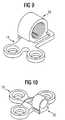
- FIG. 9shows the fastener 18 in an intermediate stage of being releasably mechanically coupled or uncoupled from plate 14.
- the distal fastener 20is best understood by reference to FIGS. 7A and 7B. it has a device-connecting portion comprising a bore 28 which accepts the distal end of the inner sleeve 302.
- the distal fasteneralso has a bone anchor-connecting portion comprising shoe 220.
- the shoemay have a substantially rectangular shape, as shown in FIG. 8B, or a substantially tapered shape, as shown in FIG. 7B.
- the shape of the shoeis selected to correspond to the shape of the cavity 162 in the plate 16.
- FIG. 10shows the fastener 20 in an intermediate stage of being releasably mechanically coupled or uncoupled from plate 16.
- the proximal shaft portion 112 of lead screw 102is slideably received within the proximal cavity portion 206 of outer sleeve 202, such that screw 102 is free to rotate relative to the outer sleeve 202.
- a region of the proximal shaft portion 110, and the adjustment end 112 of screw 102extend out from the proximal end 204 of the sleeve.
- a collar 116is attached to the screw on the extending region of the proximal shaft portion by pin 118. The collar 116 and the enlarged-diameter intermediate shaft portion 108 prevent axial translation of the screw 102 relative to outer sleeve 202. In this way, screw 120 is effectively journaled within the outer sleeve 202.
- inner sleeve 302interacts with the external screw threading 106 of lead screw 102, while at the same time the smooth exterior surface 306 of the inner sleeve is in sliding relation with the smooth inner surface of the proximal cavity portion 208 of outer sleeve 202. In this way, inner-sleeve 302 is in sliding, telescoping relation with outer sleeve 202.
- Guide pin 210is press-fit into a hole which extends through the thickness of the outer sleeve 202.
- the end of the guide pin which extends inwardsprojects sufficiently beyond the inner surface of the outer sleeve so as to interact with the longitudinal slot 308 provided on the exterior surface of the inner sleeve 302.
- longitudinal slot 308 and guide pin 210form a keyway which prevents relative rotation of the sleeves about the longitudinal axis X-X of the device (designated X-X in FIG. 3).
- Foot plates 14 and 16serve as the bone anchors, and can be made from any biocompatible material such as metal, plastic, or composites.
- the foot platesare bone plates made of a titanium alloy.
- the foot platescan be made from a bio-absorbable material. The choice of material from which to construct the foot plates is a routine design matter which depends purely on the particular medical application in which the system according to this invention is used.
- the foot platesare provided with screw holes 9 to accept the bone screws 8 which affix the device to the bone on either side of the patient's bone repair site. These holes are preferably countersunk to reduce the height of projection of the screw heads above the foot plate surface after the device is fully implanted.
- the foot plateshave a bottom, or bone-contacting surface 15 which may be flat or may be shaped to conform to the contours of the bone to which it is being attached.
- the distal foot plate 16is provided with a fastener-connecting portion comprising the slot-like engagement cavity 162 which accepts the shoe 220 of the distal fastener.
- the engagement cavitymay have a substantially rectangular shape.
- the side walls 166 of the cavityare parallel with the longitudinal axis X-X of the device, as shown in FIG. 8A, and the shoe 220 has a substantially rectangular shape corresponding to the shape of the cavity 162.
- the shape and size of the shoeis selected to allow the shoe 220 to be slidingly received by the cavity 162, creating a slip lock of the fastener 20 to foot plate 16.
- the slip lockis_a releasable mechanical coupling which is easily released by the application of a force separating the fastener 20 from foot plate 16.
- the engagement cavitymay have a substantially tapered shape, in which case side walls 166 are tapered relative to the longitudinal axis X-X of the device, as shown in FIG. 5A.
- the shoe 220 in this embodimenthas a substantially tapered shape corresponding to the shape of cavity 162.
- the shape and size of the shoe in this embodimentcreates a frictional lock of the fastener 20 to the foot plate 16.
- the frictional lockis a releasable mechanical coupling, but requires more separating force to achieve the release than does the coupling in the slip lock embodiment described above.
- the foot plateis mounted with the open end of the cavity facing the bone repair site, that is, the orientation shown in FIG. 1.
- the distraction forcewill tend to drive the shoe 220 of the distal fastener 20 into the engagement cavity 162, resulting in a releasable mechanical coupling of the fastener 20 and plate 16 resulting from the interaction of the shoe 220 with the cavity 162.
- the foot platecould be mounted with the open end of the cavity facing away from the bone repair site, such that the compression force would tend to produce the above-described coupling.
- the screw holes of plate 16are located around the cavity 162. This geometry has been found to provide a good combination of accessibility to the screws and holding strength when the device of the present invention is used in the distraction of a mandible. However, it is to be understood that the location of the screw holes and the contoured shape of the plate 16 as seen in FIG. 5A is not a critical aspect of the present invention; other screw hole placements and plate shapes could be used without departing from the scope of the present invention.
- the proximal foot plate 14is also provided with a fastener-connecting portion comprising an engagement cavity 142.
- This engagement cavitymay utilize the tapered wall geometry similar to that of the cavity 162 as described above and shown in FIG. 5A, in which case the proximal fastener 18 would have a wedge-shaped shoe similar to that of fastener 20, as shown in FIG. 7B.
- the activation force applied to the devicewould then result in a frictional lock providing a releasable mechanical coupling of the fastener 18 to the plate 14.
- the cavity 142will utilize side walls 144 which are parallel to the longitudinal axis X-X of the device, and the releasable mechanical coupling will be a slip lock.
- This detent mechanismis comprised of parts of the proximal foot plate 14, proximal fastener 18, and also sleeve 202.
- the bottom surface 145 of the cavityis provided with a depression 147, which may be in the form of a truncated spherical volume section.
- the shoe 182 of proximal fastener 18is provided with a naturally sprung arm 184. Arm 184 is provided on its bottom surface with a "bump" or projection 186 complementary to the shape of depression 147.
- the projection 186 and depression 147operate as a detent mechanism to prevent axial separation of fastener 18 from plate 14.
- the spring arm 184may deflect upwards such that the projection 186 becomes disengaged from depression 147, thus disengaging the detent mechanism.
- the force provided by spnng arm 184 alonecan serve to hold the detent mechanism in the engaged position under low forces.
- sleeve 202is threaded into bore 188. it completely prevents upwards motion of arm 184, thus preventing disengagement of the detent mechanism even when subjected to substantial forces, such as those generated during when the device is removed from the patient.
- the screw holes of plate 14are offset both to one side of axial centerline X-X of the device, and are placed such that the plate as a whole takes on the shape similar to an upper case "Y".
- This geometryhas been found to provide a good combination of accessibility to the screws and holding strength when the device of the present invention is used in the distraction of a mandible.
- the location of the screw holes and the contoured shape of the plate 14 as seen in FIG. 4Ais not a necessary part of the present invention; other screw hole placements and plate shapes could be used without departing from the scope of the present invention.
- fasteners and foot plates of the system of the present inventionare separate parts, as opposed to being integrally formed. Furthermore, due to the way in which they are mechanically joined in an conveniently releaseable locked way, they are capable of being separated after the device has served its purpose in the orthopedic procedure - the fasteners and foot plates are not permanently joined, for example by welding, nor are they joined by some other means which would make their separation difficult or inconvenient. Furthermore, the mechanical coupling of the fasteners and foot plates of the present invention does not require any additional parts to achieve the coupling.
- the surgeonmakes an incision, performs the distraction, permits consolidation, then removes the distraction assembly, leaving the foot plates affixed to the bone, and closes the incision.
- the lead screw 102is first inserted into the outer sleeve 202, after the sleeve has first been provided with guide pin 210.
- the collar 116is installed on the region of the proximal shaft portion 112 which extends out from the proximal end 204 of the outer sleeve 202.
- the collar 116is captivated on the shaft by pressing a pin through matching holes in the collar and proximal shaft portion.
- the outer sleeve 202is then threaded into the proximal fastener 18, after the fastener has first been slid into, and lockingly engaged with, foot plate 14 (using the detent mechanism described above).
- the lead screw 102is then threaded into inner sleeve 302, care being taken that the longitudinal slot on sleeve 302 is properly engaging with guide pin 210.
- the distal fastener 20is then pressed and pinned onto the distal end of the inner sleeve 302, and finally, is engaged with the distal foot plate 16.
- a small incisionis made of appropriate size to permit access to the bone necessary to attach the foot plates, and in a location appropriately offset from the bone repair site bearing in mind that only the proximal end of the distraction device will extend percutaneously through the incision once implanted.
- the assembled systemis carefully guided into the percutaneous opening and positioned relative to the bone repair site.
- the foot platesare then affixed to the bone using bone screws, and the incision is closed, with only the proximal end of the device extending percutaneously.
- the distraction osteogenesis procedureis performed by turning the lead screw using the tool interface 114. Counter-clockwise rotation of the screw will result in axial lengthening of the device, resulting in a distraction force being communicated to the bones through the foot plates.
- the deviceis removed, or disengaged, by reversing the direction of rotation of the lead screw 102.
- the amount of reverse (i.e., clockwise) rotationdepends on the thread pitch of the lead screw, but typically, at least ten full clockwise rotations will be required to cause the distal fastener 20 to disengage from the distal foot plate 16.
- the sleeve 202is unthreaded from fastener 18 sufficiently to allow sprung arm 184 to flex, such that when the device is now pushed towards the bone surface, the detent mechanism holding proximal fastener 18 to corresponding proximal foot plate 14 is released, unseating the device from the proximal foot plate.
- the entire activation portion of the device(lead screw, sleeves, and fasteners) is now disengaged from the patient, and can now be gently removed through the percutaneous port, leaving only the foot plates (and associated bone screws) in the patient.
- the percutaneous portis closed using standard surgical procedures.
- the foot plates 14 and 16may be formed of a bio-absorbable material. Any bio-absorbable material may be used, either natural or synthetic (for example polylactides, polyglycolides, or polyesteramides). By forming the foot plates from a bio-absorbable material, the foot plates may be left in situ after the completion of the distraction osteogenesis. By appropriate selection of the bio-absorbable materials, the foot plates will begin to absorb after their mechanical strength is no longer required for the procedure, and over time the foot plates will substantially or totally be resorbed by the body. By eliminating the need for a second surgical procedure to remove the foot plates, this invention advantageously reduces health care costs as well as the medical risks associated with even the most carefully performed surgery.
- the bone screws 8 used to affix the foot plates to the bonemay also be made of bio-absorbable material, either the same material as the foot plates, or a different material. In this case, it may be desirable to select the bio-absorbable materials such that the screws are not absorbed until after the foot plates are substantially absorbed. If the screws were to be absorbed first, this would create the undesirable situation of the foot plates coming loose from the attachment site and being free to migrate subcutaneously.
- the particular linear distractor embodiment shown in FIG. 1could be used, without any structural modifications, in well-known orthopedic applications other than mandibular distraction; for example it is entirely appropriate for use in the distraction of long bones.
- various other well-known distraction and fixation assembliescould be substituted for the distraction assembly 12 described above, without departing from the scope of the present invention.
- an assembly providing both linear and angular distractioncould be provided to bridge the bone repair site and mechanically link the foot plates.
Landscapes
- Health & Medical Sciences (AREA)
- Orthopedic Medicine & Surgery (AREA)
- Life Sciences & Earth Sciences (AREA)
- Surgery (AREA)
- Medical Informatics (AREA)
- Engineering & Computer Science (AREA)
- Biomedical Technology (AREA)
- Heart & Thoracic Surgery (AREA)
- Nuclear Medicine, Radiotherapy & Molecular Imaging (AREA)
- Molecular Biology (AREA)
- Animal Behavior & Ethology (AREA)
- General Health & Medical Sciences (AREA)
- Public Health (AREA)
- Veterinary Medicine (AREA)
- Neurology (AREA)
- Surgical Instruments (AREA)
- Prostheses (AREA)
Abstract
Description
Claims (13)
- An orthopedic system comprising:wherebyA) at least two bone anchors for anchoring the system to a patient's bone, each anchor havinga bone-contacting surface and a fastener-connecting portion; andB) a fastener (18;20) associated with each of the bone anchors, each fastener (18;20) having adevice-connecting portion and an anchor-connecting portion,C) the anchor-connecting portion of the fastener (18;20) and the fastener-connecting portion of the associated boneanchor (14,16) providing a releasable mechanical coupling of the fastener (18;20) to the bone anchor;andC) an orthopedic device coupled to the device-connecting portions of each fastener (18;20),D) the bone anchors are bone plates (14;16); andE) after the orthopedic procedure is complete, the mechanical coupling of the bone plates(14;16) to the fasteners (18;20) can be released, allowing the fasteners (18;20) and orthopedicdevice to be removed from the patient without removal of the bone plates.
- Orthopedic system according to claim 1, wherein the bone plates (14;16) are made of a bio-absorbablematerial.
- Orthopedic system according to claim 1 or 2, wherein each bone plate (14;16) has at leastone screw hole (9) adapted to receive a bone screw (8) to anchor the plate (14;16) to the bone.
- Orthopedic system according to claim 3, wherein the bone plates (14;16) are made of a bio-absorbablematerial.
- Orthopedic system according to claim 4, further comprising bone screws (8) made of a bio-absorbablematerial which takes at least as long as the bone plates (14;16) to be absorbed inthe patient.
- Orthopedic system according to one of the claims 1 to 5, wherein the orthopedic device is adistractor.
- Orthopedic system according to claim 1, wherein the releasable coupling of at leastone of the bone plates (14;16) and the associated fastener (18;20) comprises a detentmechanism, the release of the detent mechanism being prevented when the orthopedicdevice is substantially fully coupled to the device-connecting portion of that fastener(18;20) and release of the detent mechanism being permitted when the orthopedicdevice is at least partially uncoupled from the device-connecting portion of that fastener(18;20).
- Orthopedic system according to claim 1, wherein the anchor-connecting portion of atleast one fastener (18;20) comprises a shoe (182;220), and the fastener-connectingportion of the bone plate (14;16) associated with that at least one fastener (18;20)comprises an engagement cavity (142;162); wherein the shoe (182;220) is sized andshaped to be slidingly received by the engagement cavity (142;162).
- Orthopedic system according to claim 8, wherein the shoe (182;220) and theassociated engagement cavity (142;162) have a corresponding substantiallyrectangular shape; whereby the releasable mechanical coupling is a slip lock.
- Orthopedic system according to claim 8, wherein the shoe (182;220) and theassociated engagement cavity (142;162) have a corresponding substantially taperedshape; whereby the releasable mechanical coupling is a frictional lock.
- Orthopedic distraction system for distracting first and second osteotomicallyseparated bone sections of a patient according to claim 6, wherein the systemcomprises:A) a distal bone plate (16) for subcutaneous implantation and attachment to the firstbone section, the distal bone plate (16) having screw holes (9) adapted to receive bonescrews (8), a bone-contacting surface, and a first engagement cavity (162) having asubstantially rectangular shape;B) a distal fastener (20) associated with the distal bone plate (16) and having a device-connectingportion and a shoe (220), the shoe (220) being shaped and sized tocorrespond to the first engagement cavity (162); whereby the shoe (220) is slidingly accepted by the first engagement cavity (162) producing a slip lock of thedistal fastener (20) to the distal bone plate (16);C) a proximal bone plate (14) for subcutaneous implantation and attachment to thesecond bone section, the proximal bone plate (14) having screw holes (9) adapted toreceive bone screws (8), a bone-contacting surface, and a second engagementcavity (142);D) a proximal fastener (18) associated with the proximal bone plate (14) and having adevice-connecting portion and a anchor-connecting portion, wherein proximal boneplate (14) and proximal fastener (18) are releasably coupled by a detent mechanism;andE) an orthopedic device coupled to the device-connecting portions of each fastener(18;20), whereinF) the release of the detent mechanism is prevented when the orthopedic device is atleast substantially fully coupled to the device-connecting portion of the proximalfastener (18), and release of the detent mechanism is permitted when the orthopedicdevice is at least partially uncoupled from the device-connecting portion of theproximal fastener (18), and further wherein both fasteners (18;20) can be releasedfrom their corresponding bone plates (14;16), allowing the fasteners (18;20) anddistraction device to be removed from the patient without removal of the bone plates(14;16).
- Orthopedic system of claim 11, wherein the bone plates (14;16) are made of abio-absorbable material.
- Orthopedic system of claim 12, further comprising bone screws (8) made of a bio-absorbablematerial which takes at least as long as the bone plates (14;16) to beabsorbed in the patient.
Applications Claiming Priority (3)
| Application Number | Priority Date | Filing Date | Title |
|---|---|---|---|
| US09/274,698US6423069B1 (en) | 1999-03-23 | 1999-03-23 | Orthopedic system having detachable bone anchors |
| US274698 | 1999-03-23 | ||
| PCT/CH2000/000136WO2000056235A1 (en) | 1999-03-23 | 2000-03-09 | Orthopedic system having detachable bone anchors |
Publications (2)
| Publication Number | Publication Date |
|---|---|
| EP1162919A1 EP1162919A1 (en) | 2001-12-19 |
| EP1162919B1true EP1162919B1 (en) | 2003-12-10 |
Family
ID=23049260
Family Applications (1)
| Application Number | Title | Priority Date | Filing Date |
|---|---|---|---|
| EP00906136AExpired - LifetimeEP1162919B1 (en) | 1999-03-23 | 2000-03-09 | Orthopedic system having detachable bone anchors |
Country Status (14)
| Country | Link |
|---|---|
| US (3) | US6423069B1 (en) |
| EP (1) | EP1162919B1 (en) |
| JP (1) | JP4357123B2 (en) |
| KR (1) | KR100604453B1 (en) |
| CN (1) | CN1188085C (en) |
| AT (1) | ATE255853T1 (en) |
| AU (1) | AU746972B2 (en) |
| CA (1) | CA2364691C (en) |
| DE (1) | DE60007092T2 (en) |
| ES (1) | ES2209822T3 (en) |
| NZ (1) | NZ513994A (en) |
| TW (1) | TW515711B (en) |
| WO (1) | WO2000056235A1 (en) |
| ZA (1) | ZA200106770B (en) |
Cited By (1)
| Publication number | Priority date | Publication date | Assignee | Title |
|---|---|---|---|---|
| EP2742883A1 (en) | 2012-12-12 | 2014-06-18 | Stryker Leibinger GmbH & Co. KG | Surgical distance adjusting assembly for a bone distractor |
Families Citing this family (80)
| Publication number | Priority date | Publication date | Assignee | Title |
|---|---|---|---|---|
| US6423069B1 (en)* | 1999-03-23 | 2002-07-23 | Synthes (Usa) | Orthopedic system having detachable bone anchors |
| WO2001041662A1 (en)* | 1999-12-09 | 2001-06-14 | Macropore | Completely resorbable connective tissue distraction devices and techniques |
| AR033840A1 (en)* | 2000-10-04 | 2004-01-07 | Synthes Ag | AN ORTHOPEDIC DEVICE TO MODIFY THE DISTANCE BETWEEN THE MAXILAR AND THE CIGOMA OF A PATIENT |
| US6908469B2 (en) | 2000-10-04 | 2005-06-21 | Synthes (Usa) | Compact maxillary distractor |
| YU73000A (en)* | 2000-11-22 | 2003-02-28 | Milorad Mitković | Internal fixator of bones |
| JP2002263128A (en)* | 2001-03-12 | 2002-09-17 | Koseki Ika Kk | Maxilla extending device |
| BE1014998A3 (en)* | 2001-05-02 | 2004-08-03 | Mommaerts Maurice | Distraction device for repairing jawbone following osteotomy, includes expansion screws, plates and cylinder for bidirectional distraction |
| JP2003135478A (en)* | 2001-11-05 | 2003-05-13 | Koseki Ika Kk | Alveolar bone extender |
| US20060235408A1 (en)* | 2001-11-09 | 2006-10-19 | Wang Robert C | Apparatus and methods for bone fracture fixation |
| US7235077B1 (en) | 2001-11-09 | 2007-06-26 | Board Of Regents Of The University And Community College System Of Nevada On Behalf Of The University Of Nevada, Reno | Bone fixation device and method |
| US7892241B2 (en) | 2001-11-20 | 2011-02-22 | Osteomed, L.P. | Method and system for facial osteodistraction using a cannulated device |
| US7621922B2 (en)* | 2001-11-20 | 2009-11-24 | Osteomed L.P. | Facial osteodistraction device |
| US6589250B2 (en)* | 2001-11-20 | 2003-07-08 | Stephen A. Schendel | Maxillary distraction device |
| US7311711B2 (en)* | 2001-12-21 | 2007-12-25 | Cole J Dean | Surgical distractor frame |
| DE50312765D1 (en)* | 2002-01-23 | 2010-07-15 | Albino Triaca | DISTRACTION DEVICE FOR ORTHODONTIC / SURGICAL PURPOSES ON THE LOWER SIDE |
| ATE476930T1 (en) | 2002-02-20 | 2010-08-15 | Stephen Ritland | DEVICE FOR CONNECTING HAND SCREWS |
| DE10212815A1 (en)* | 2002-03-22 | 2003-10-02 | Ernst Fuchs | Distraction device for osteogenesis |
| ATE552789T1 (en) | 2002-05-08 | 2012-04-15 | Stephen Ritland | DYNAMIC FIXATION DEVICE |
| US7291152B2 (en)* | 2003-04-18 | 2007-11-06 | Abdou M Samy | Bone fixation system and method of implantation |
| US20050049595A1 (en) | 2003-09-03 | 2005-03-03 | Suh Sean S. | Track-plate carriage system |
| US7909860B2 (en) | 2003-09-03 | 2011-03-22 | Synthes Usa, Llc | Bone plate with captive clips |
| US7635366B2 (en)* | 2003-12-29 | 2009-12-22 | Abdou M Samy | Plating system for bone fixation and method of implantation |
| US20050234448A1 (en)* | 2004-03-19 | 2005-10-20 | Mccarthy James | Implantable bone-lengthening device |
| US7604643B2 (en)* | 2004-04-06 | 2009-10-20 | Synthes Usa, Llc | Adjustable tool for cannulated fasteners |
| US7485121B2 (en) | 2004-05-04 | 2009-02-03 | Synthes (Usa) | Midface distractor |
| US7686836B2 (en)* | 2004-05-13 | 2010-03-30 | Kls-Martin, L.P. | Bone distractor and method |
| EP1758511A4 (en)* | 2004-06-14 | 2008-12-03 | M S Abdou | Occipital fixation system and method of use |
| US7875033B2 (en)* | 2004-07-19 | 2011-01-25 | Synthes Usa, Llc | Bone distraction apparatus |
| US7854752B2 (en) | 2004-08-09 | 2010-12-21 | Theken Spine, Llc | System and method for dynamic skeletal stabilization |
| CA2574277A1 (en)* | 2004-08-09 | 2006-02-23 | Innovative Spinal Technologies, Inc. | System and method for dynamic skeletal stabilization |
| US20060058798A1 (en)* | 2004-08-24 | 2006-03-16 | Roman Shawn D | Bone distractor with ratchet mechanism |
| US7771434B2 (en)* | 2004-10-08 | 2010-08-10 | Kls-Martin, Lp | Bone distractor apparatus |
| WO2006058221A2 (en) | 2004-11-24 | 2006-06-01 | Abdou Samy M | Devices and methods for inter-vertebral orthopedic device placement |
| AU2006214001B2 (en) | 2005-02-18 | 2011-05-26 | Samy Abdou | Devices and methods for dynamic fixation of skeletal structure |
| US8870920B2 (en)* | 2005-10-07 | 2014-10-28 | M. Samy Abdou | Devices and methods for inter-vertebral orthopedic device placement |
| US8025681B2 (en) | 2006-03-29 | 2011-09-27 | Theken Spine, Llc | Dynamic motion spinal stabilization system |
| US8303630B2 (en)* | 2006-07-27 | 2012-11-06 | Samy Abdou | Devices and methods for the minimally invasive treatment of spinal stenosis |
| WO2008024373A2 (en)* | 2006-08-21 | 2008-02-28 | Abdou M Samy | Bone screw systems and methods of use |
| US20080065073A1 (en)* | 2006-09-08 | 2008-03-13 | Michael Perriello | Offset dynamic motion spinal stabilization system |
| US7909610B1 (en) | 2006-12-21 | 2011-03-22 | Amato Craniofacial Engineering, LLC | Computer-aided system of orthopedic surgery |
| DE102007028087B4 (en)* | 2007-06-11 | 2014-05-15 | Aesculap Ag | Modular implant part and knee joint prosthesis |
| WO2009046024A1 (en)* | 2007-10-01 | 2009-04-09 | Physical Sciences, Inc. | Distraction osteogenesis methods and devices |
| AU2008318535B2 (en)* | 2007-10-31 | 2014-06-19 | Wright Medical Technology, Inc. | Orthopedic device |
| US8968192B2 (en)* | 2008-06-06 | 2015-03-03 | Warsaw Orthopedic, Inc. | Systems and methods for tissue retraction |
| EP2133033A1 (en)* | 2008-06-11 | 2009-12-16 | Surgi-Tec NV | Alveolar distractor |
| DE102008034300A1 (en)* | 2008-07-23 | 2010-01-28 | Lucas Automotive Gmbh | Vehicle disc brake |
| US20100075270A1 (en)* | 2008-09-19 | 2010-03-25 | Figueroa Alvaro A | Angularly adjustable maxillary distractor and method of distraction |
| US20100104999A1 (en)* | 2008-10-23 | 2010-04-29 | Bulloch Scott E | Apparatus, System, and Method for Intra-Oral Distraction |
| EP2289440B1 (en)* | 2009-08-27 | 2013-05-29 | Stryker Leibinger GmbH & Co. KG | Bone anchor, orthopaedic device and orthopaedic system |
| JP5710622B2 (en)* | 2009-09-24 | 2015-04-30 | ジンテス ゲゼルシャフト ミット ベシュレンクテル ハフツング | Distractor with removable stirrup base |
| US8764806B2 (en) | 2009-12-07 | 2014-07-01 | Samy Abdou | Devices and methods for minimally invasive spinal stabilization and instrumentation |
| US8435270B2 (en) | 2010-04-29 | 2013-05-07 | Synthes Usa, Llc | Orthognathic implant and methods of use |
| US9066733B2 (en) | 2010-04-29 | 2015-06-30 | DePuy Synthes Products, Inc. | Orthognathic implant and methods of use |
| US9308026B2 (en)* | 2011-04-20 | 2016-04-12 | Ramon L. Ruiz | Distractor device including multiple diameter internal post and related methods |
| EP2701620A1 (en) | 2011-04-26 | 2014-03-05 | Synthes GmbH | Hinged fixation devices for combined upper jaw correction |
| US8845728B1 (en) | 2011-09-23 | 2014-09-30 | Samy Abdou | Spinal fixation devices and methods of use |
| US20130226240A1 (en) | 2012-02-22 | 2013-08-29 | Samy Abdou | Spinous process fixation devices and methods of use |
| US20130261624A1 (en)* | 2012-03-30 | 2013-10-03 | Osteomed Llc | Maxillary implant for advancement, expansion and stabilization of repositioned bone sections |
| US9198767B2 (en) | 2012-08-28 | 2015-12-01 | Samy Abdou | Devices and methods for spinal stabilization and instrumentation |
| CN103654978B (en)* | 2012-09-14 | 2016-06-29 | 陈碧芝 | Alveolar bone augmentation device and its longitudinal augmentation kit |
| US9320617B2 (en) | 2012-10-22 | 2016-04-26 | Cogent Spine, LLC | Devices and methods for spinal stabilization and instrumentation |
| EP2735276B1 (en) | 2012-11-27 | 2018-09-05 | Stryker European Holdings I, LLC | Pediatric internal mandibular distractor |
| US9468479B2 (en) | 2013-09-06 | 2016-10-18 | Cardinal Health 247, Inc. | Bone plate |
| USD779065S1 (en) | 2014-10-08 | 2017-02-14 | Nuvasive, Inc. | Anterior cervical bone plate |
| US9931138B2 (en)* | 2014-10-15 | 2018-04-03 | Globus Medical, Inc. | Orthopedic extendable rods |
| FR3027791A1 (en)* | 2014-11-03 | 2016-05-06 | Yoomed | DEVICE FOR INDUCING OR CORRECTING MANDIBULAR GROWTH. |
| WO2016073743A1 (en)* | 2014-11-05 | 2016-05-12 | Johnston Jr Thomas S | Detachable actuator arm for distraction devices |
| US10166053B2 (en) | 2014-12-30 | 2019-01-01 | Stryker European Holdings I, Llc | Distractor with bidirectional rotation control |
| RU2599370C1 (en)* | 2015-04-20 | 2016-10-10 | Государственное Бюджетное учреждение здравоохранения города Москвы "Детская городская клиническая больница святого Владимира Департамента здравоохранения города Москвы" | Method for expansion of ramus of mandible and compression-expansion device for its implementation |
| US10857003B1 (en) | 2015-10-14 | 2020-12-08 | Samy Abdou | Devices and methods for vertebral stabilization |
| US10744000B1 (en) | 2016-10-25 | 2020-08-18 | Samy Abdou | Devices and methods for vertebral bone realignment |
| US10973648B1 (en) | 2016-10-25 | 2021-04-13 | Samy Abdou | Devices and methods for vertebral bone realignment |
| RU2676399C1 (en)* | 2017-10-03 | 2018-12-28 | Федеральное Государственное Бюджетное Образовательное Учреждение Высшего Образования Московский государственный медико-стоматологический университет имени А.И. Евдокимова Министерства здравоохранения Российской Федерации (ФГБОУ ВО МГМСУ имени А.И. Евдокимова Минздрава России) | Implant for osteosynthesis of fragments in fracture of condylar process of mandible |
| KR102108106B1 (en)* | 2017-10-20 | 2020-05-08 | 주식회사 제일메디칼코퍼레이션 | Bone distractor |
| US11399871B2 (en)* | 2018-06-21 | 2022-08-02 | Wendy L. Johnston | Bone distraction device having a quick release disengagement mechanism |
| BR112021003874A2 (en)* | 2018-08-29 | 2021-05-18 | Amdt Holdings, Inc. | adjustable support sets for external fastening systems |
| US11179248B2 (en) | 2018-10-02 | 2021-11-23 | Samy Abdou | Devices and methods for spinal implantation |
| US11806055B2 (en)* | 2019-09-19 | 2023-11-07 | Kls Martin, Inc. | Customized bone distraction method, device and system |
| US20210186643A1 (en)* | 2019-12-20 | 2021-06-24 | Endotact | Distraction device with reflector |
| US12213703B2 (en) | 2022-02-23 | 2025-02-04 | DePuy Synthes Products, Inc. | Three dimensional distractors |
Family Cites Families (54)
| Publication number | Priority date | Publication date | Assignee | Title |
|---|---|---|---|---|
| US2250417A (en)* | 1939-12-02 | 1941-07-22 | Zimmer Mfg Company | Fracture reduction and retention device |
| US3604414A (en) | 1968-08-29 | 1971-09-14 | Nicomedes Borges | Bone setting device |
| DE2601938C3 (en) | 1976-01-20 | 1979-08-02 | Messerschmitt-Boelkow-Blohm Gmbh, 8000 Muenchen | Telescopically adjustable guide rail for a distraction device |
| DE3134120A1 (en) | 1981-08-28 | 1983-03-17 | Anton Dr. 4400 Münster Härle | CLAMPING DEVICE FOR AN OSTEOSYNTHESIS PLATE |
| US4550449A (en) | 1982-11-08 | 1985-11-05 | Johnson & Johnson Products Inc. | Absorbable bone fixation device |
| US5013315A (en) | 1985-07-12 | 1991-05-07 | Minnesota Mining And Manufacturing Company | Semiabsorbable bone plate spacer |
| US5152687A (en) | 1987-10-30 | 1992-10-06 | Kyocera Corporation | Composite implant member |
| DE3831657A1 (en)* | 1988-09-17 | 1990-03-22 | Boehringer Ingelheim Kg | DEVICE FOR THE OSTEOSYNTHESIS AND METHOD FOR THE PRODUCTION THEREOF |
| US5522817A (en) | 1989-03-31 | 1996-06-04 | United States Surgical Corporation | Absorbable surgical fastener with bone penetrating elements |
| CA2013539C (en) | 1989-03-31 | 1999-07-06 | Thomas W. Sander | Absorbable surgical fastener with bone penetrating elements |
| DE4007306C1 (en) | 1990-03-08 | 1991-05-23 | Eska Medical Luebeck Medizintechnik Gmbh & Co, 2400 Luebeck, De | Implant for use in bone surgery - comprises two plates geared to allow relative external adjustment after fixture |
| US5147358A (en) | 1990-10-23 | 1992-09-15 | Remmler Daniel J | Cranial fixation-distraction and positioning apparatus and method |
| US5820369A (en) | 1991-02-25 | 1998-10-13 | Nobel Biocare Ab | Subperiosteal bone anchor |
| CA2062012C (en) | 1991-03-05 | 2003-04-29 | Randall D. Ross | Bioabsorbable interference bone fixation screw |
| CA2063159C (en) | 1991-03-22 | 1999-06-15 | Thomas W. Sander | Orthopedic fastener |
| US5275601A (en) | 1991-09-03 | 1994-01-04 | Synthes (U.S.A) | Self-locking resorbable screws and plates for internal fixation of bone fractures and tendon-to-bone attachment |
| US5201733A (en) | 1992-01-21 | 1993-04-13 | Etheredge Iii James L | Method and apparatus for internal fixation of fractures |
| US5171279A (en) | 1992-03-17 | 1992-12-15 | Danek Medical | Method for subcutaneous suprafascial pedicular internal fixation |
| US5885283A (en) | 1992-08-04 | 1999-03-23 | Gittleman; Neal B. | Osteogenic mandibular distention apparatus and method |
| US5484439A (en) | 1992-09-16 | 1996-01-16 | Alphatec Manufacturing, Inc. | Modular femur fixation device |
| US5904479A (en) | 1992-11-12 | 1999-05-18 | Staples; Jeffrey J. | Orthodontic palate expander apparatus |
| US5364396A (en) | 1993-03-29 | 1994-11-15 | Robinson Randolph C | Distraction method and apparatus |
| DE4316794C1 (en) | 1993-05-19 | 1994-10-13 | Joerg Bischof | Device for the distraction of bones |
| US6187004B1 (en) | 1993-07-14 | 2001-02-13 | Jeffrey A. Fearon | Subcutaneous bone expansion device |
| DE9401911U1 (en) | 1994-02-05 | 1994-06-16 | Normed Medizin-Technik Vertriebs-GmbH, 78532 Tuttlingen | Device for distraction of bone segments |
| US5829971A (en) | 1994-04-04 | 1998-11-03 | Razdolsky; Yan | Osteodistraction device for use in mandibular distraction osteogenesis and a method of making the device |
| US5622493A (en) | 1994-04-04 | 1997-04-22 | Razdolsky; Yan | Mandibular distration device for use in mandibular distraction osteogenesis |
| CA2186199A1 (en) | 1994-04-04 | 1995-10-05 | Yan Razdolsky | Method of making an oral osteodistraction device |
| US5735688A (en) | 1996-02-22 | 1998-04-07 | Razdolsky; Yan | Attachments for a mandibular distraction device for use in mandibular distraction osteogenesis |
| DE29501880U1 (en) | 1995-02-06 | 1995-05-24 | Karl Leibinger Medizintechnik GmbH & Co. KG, 78570 Mühlheim | Bone extension device |
| JP3566967B2 (en) | 1995-07-03 | 2004-09-15 | ジンテーズ アクチエンゲゼルシャフト クール | Bone fragment fixation device |
| EP0770359A1 (en)* | 1995-10-05 | 1997-05-02 | Medicon e.G. Chirurgiemechaniker-Genossenschaft | Distraction device for bone segments |
| DE19538323A1 (en) | 1995-10-14 | 1997-04-17 | Mueller Paul A | Traction device for correction of an upper jaw |
| EP0865258B1 (en) | 1995-12-01 | 2000-06-21 | David A. Walker | Telescopic bone plate for use in bone lengthening by distraction osteogenesis |
| US5672177A (en) | 1996-01-31 | 1997-09-30 | The General Hospital Corporation | Implantable bone distraction device |
| US5891144A (en)* | 1996-05-10 | 1999-04-06 | Jaquet Orthopedie S.A. | External fixator |
| US5827287A (en) | 1996-06-10 | 1998-10-27 | Howmedica Inc. | High strength internal bone fixation devices and process for forming same |
| US5700263A (en) | 1996-06-17 | 1997-12-23 | Schendel; Stephen A. | Bone distraction apparatus |
| BE1010602A4 (en) | 1996-09-04 | 1998-11-03 | Mommaerts Maurice Yves | Apparatus for intra-oral distractieosteotomie. |
| DE19637938A1 (en) | 1996-09-17 | 1998-03-26 | Juergen Harms | Bone plate |
| US5895387A (en) | 1996-10-09 | 1999-04-20 | Romulo Guerrero | Method of craniofacial bone distraction |
| US5976142A (en) | 1996-10-16 | 1999-11-02 | Chin; Martin | Apparatus and method for distraction osteogenesis of small alveolar bone |
| US5769850A (en)* | 1996-10-16 | 1998-06-23 | Chin; Martin | Apparatus and method for submergible, self-retaining distraction osteogenesis |
| US5885290A (en) | 1996-12-09 | 1999-03-23 | Guerrero; Cesar A. | Intra-oral bone distraction device |
| US5827286A (en)* | 1997-02-14 | 1998-10-27 | Incavo; Stephen J. | Incrementally adjustable tibial osteotomy fixation device and method |
| US6113599A (en)* | 1997-06-04 | 2000-09-05 | Kalpa Engineering, Inc. | Apparatus for internal mandibular distraction |
| WO1999004715A1 (en) | 1997-07-21 | 1999-02-04 | Roger Minoretti | Intraoral distractor for callus distraction in the lower jaw |
| DE29716635U1 (en) | 1997-09-16 | 1997-10-30 | Karl Leibinger Medizintechnik GmbH & Co. KG, 78570 Mühlheim | Distraction device for the treatment of bone defects |
| US6171313B1 (en) | 1998-07-02 | 2001-01-09 | Yan Razdolsky | Distraction apparatus for subapical osteotomy and vertical segment distraction and ridge augmentation |
| BR9815996A (en) | 1998-08-25 | 2001-05-02 | Medartis Ag | Osteosynthetic fixation device |
| FR2787698B1 (en) | 1998-10-27 | 2001-05-18 | Obl | INTRAORAL MANDIBULAR DISTRACTOR |
| US6139316A (en) | 1999-01-26 | 2000-10-31 | Sachdeva; Rohit C. L. | Device for bone distraction and tooth movement |
| US6423069B1 (en) | 1999-03-23 | 2002-07-23 | Synthes (Usa) | Orthopedic system having detachable bone anchors |
| US6277124B1 (en) | 1999-10-27 | 2001-08-21 | Synthes (Usa) | Method and apparatus for ratcheting adjustment of bone segments |
- 1999
- 1999-03-23USUS09/274,698patent/US6423069B1/ennot_activeExpired - Lifetime
- 2000
- 2000-03-09CACA002364691Apatent/CA2364691C/ennot_activeExpired - Fee Related
- 2000-03-09ESES00906136Tpatent/ES2209822T3/ennot_activeExpired - Lifetime
- 2000-03-09ATAT00906136Tpatent/ATE255853T1/enactive
- 2000-03-09WOPCT/CH2000/000136patent/WO2000056235A1/enactiveIP Right Grant
- 2000-03-09CNCNB008053626Apatent/CN1188085C/ennot_activeExpired - Fee Related
- 2000-03-09JPJP2000606144Apatent/JP4357123B2/ennot_activeExpired - Fee Related
- 2000-03-09DEDE60007092Tpatent/DE60007092T2/ennot_activeExpired - Lifetime
- 2000-03-09KRKR1020017012062Apatent/KR100604453B1/ennot_activeExpired - Fee Related
- 2000-03-09AUAU27920/00Apatent/AU746972B2/ennot_activeCeased
- 2000-03-09NZNZ513994Apatent/NZ513994A/ennot_activeIP Right Cessation
- 2000-03-09EPEP00906136Apatent/EP1162919B1/ennot_activeExpired - Lifetime
- 2000-03-13TWTW089104478Apatent/TW515711B/ennot_activeIP Right Cessation
- 2001
- 2001-08-16ZAZA200106770Apatent/ZA200106770B/enunknown
- 2002
- 2002-04-22USUS10/127,775patent/US6884243B2/ennot_activeExpired - Lifetime
- 2005
- 2005-04-22USUS11/113,277patent/US20050209594A1/ennot_activeAbandoned
Cited By (1)
| Publication number | Priority date | Publication date | Assignee | Title |
|---|---|---|---|---|
| EP2742883A1 (en) | 2012-12-12 | 2014-06-18 | Stryker Leibinger GmbH & Co. KG | Surgical distance adjusting assembly for a bone distractor |
Also Published As
| Publication number | Publication date |
|---|---|
| KR100604453B1 (en) | 2006-07-26 |
| CA2364691A1 (en) | 2000-09-28 |
| JP4357123B2 (en) | 2009-11-04 |
| TW515711B (en) | 2003-01-01 |
| CN1345204A (en) | 2002-04-17 |
| AU2792000A (en) | 2000-10-09 |
| EP1162919A1 (en) | 2001-12-19 |
| CA2364691C (en) | 2007-11-20 |
| ES2209822T3 (en) | 2004-07-01 |
| US20020116002A1 (en) | 2002-08-22 |
| US6423069B1 (en) | 2002-07-23 |
| WO2000056235A1 (en) | 2000-09-28 |
| CN1188085C (en) | 2005-02-09 |
| ZA200106770B (en) | 2002-03-05 |
| DE60007092D1 (en) | 2004-01-22 |
| US6884243B2 (en) | 2005-04-26 |
| DE60007092T2 (en) | 2004-06-09 |
| US20050209594A1 (en) | 2005-09-22 |
| ATE255853T1 (en) | 2003-12-15 |
| KR20020036939A (en) | 2002-05-17 |
| AU746972B2 (en) | 2002-05-09 |
| JP2002538931A (en) | 2002-11-19 |
| NZ513994A (en) | 2003-02-28 |
Similar Documents
| Publication | Publication Date | Title |
|---|---|---|
| EP1162919B1 (en) | Orthopedic system having detachable bone anchors | |
| EP1499250B1 (en) | Compact maxillary distractor | |
| JP4945439B2 (en) | Sternum repair system | |
| US5474553A (en) | System for setting tubular bone fractures | |
| US7645279B1 (en) | Bone fixation method | |
| US20100152737A1 (en) | Adjustable bone plate | |
| AU2005302550A1 (en) | Adjustable bone plate | |
| JP2003512124A (en) | Method and apparatus for pawl adjustment of bone segments | |
| JP2008546449A5 (en) | ||
| CA2424108C (en) | Maxillary distractor | |
| CA2029897A1 (en) | Setting device for tubular bone fractures | |
| US7914531B1 (en) | Bone fixation system and methods |
Legal Events
| Date | Code | Title | Description |
|---|---|---|---|
| PUAI | Public reference made under article 153(3) epc to a published international application that has entered the european phase | Free format text:ORIGINAL CODE: 0009012 | |
| 17P | Request for examination filed | Effective date:20010806 | |
| AK | Designated contracting states | Kind code of ref document:A1 Designated state(s):AT BE CH CY DE DK ES FI FR GB GR IE IT LI LU MC NL PT SE | |
| AX | Request for extension of the european patent | Free format text:AL;LT;LV;MK;RO;SI | |
| GRAH | Despatch of communication of intention to grant a patent | Free format text:ORIGINAL CODE: EPIDOS IGRA | |
| GRAS | Grant fee paid | Free format text:ORIGINAL CODE: EPIDOSNIGR3 | |
| GRAA | (expected) grant | Free format text:ORIGINAL CODE: 0009210 | |
| AK | Designated contracting states | Kind code of ref document:B1 Designated state(s):AT BE CH CY DE DK ES FI FR GB GR IE IT LI LU MC NL PT SE | |
| PG25 | Lapsed in a contracting state [announced via postgrant information from national office to epo] | Ref country code:FR Free format text:LAPSE BECAUSE OF FAILURE TO SUBMIT A TRANSLATION OF THE DESCRIPTION OR TO PAY THE FEE WITHIN THE PRESCRIBED TIME-LIMIT Effective date:20031210 Ref country code:CY Free format text:LAPSE BECAUSE OF FAILURE TO SUBMIT A TRANSLATION OF THE DESCRIPTION OR TO PAY THE FEE WITHIN THE PRESCRIBED TIME-LIMIT Effective date:20031210 Ref country code:BE Free format text:LAPSE BECAUSE OF FAILURE TO SUBMIT A TRANSLATION OF THE DESCRIPTION OR TO PAY THE FEE WITHIN THE PRESCRIBED TIME-LIMIT Effective date:20031210 Ref country code:FI Free format text:LAPSE BECAUSE OF FAILURE TO SUBMIT A TRANSLATION OF THE DESCRIPTION OR TO PAY THE FEE WITHIN THE PRESCRIBED TIME-LIMIT Effective date:20031210 | |
| REG | Reference to a national code | Ref country code:GB Ref legal event code:FG4D | |
| REG | Reference to a national code | Ref country code:CH Ref legal event code:NV Representative=s name:DR. LUSUARDI AG Ref country code:CH Ref legal event code:EP | |
| REG | Reference to a national code | Ref country code:IE Ref legal event code:FG4D | |
| REF | Corresponds to: | Ref document number:60007092 Country of ref document:DE Date of ref document:20040122 Kind code of ref document:P | |
| PG25 | Lapsed in a contracting state [announced via postgrant information from national office to epo] | Ref country code:LU Free format text:LAPSE BECAUSE OF NON-PAYMENT OF DUE FEES Effective date:20040309 Ref country code:IE Free format text:LAPSE BECAUSE OF NON-PAYMENT OF DUE FEES Effective date:20040309 | |
| PG25 | Lapsed in a contracting state [announced via postgrant information from national office to epo] | Ref country code:SE Free format text:LAPSE BECAUSE OF FAILURE TO SUBMIT A TRANSLATION OF THE DESCRIPTION OR TO PAY THE FEE WITHIN THE PRESCRIBED TIME-LIMIT Effective date:20040310 Ref country code:GR Free format text:LAPSE BECAUSE OF FAILURE TO SUBMIT A TRANSLATION OF THE DESCRIPTION OR TO PAY THE FEE WITHIN THE PRESCRIBED TIME-LIMIT Effective date:20040310 Ref country code:DK Free format text:LAPSE BECAUSE OF FAILURE TO SUBMIT A TRANSLATION OF THE DESCRIPTION OR TO PAY THE FEE WITHIN THE PRESCRIBED TIME-LIMIT Effective date:20040310 | |
| PG25 | Lapsed in a contracting state [announced via postgrant information from national office to epo] | Ref country code:MC Free format text:LAPSE BECAUSE OF NON-PAYMENT OF DUE FEES Effective date:20040331 | |
| LTIE | Lt: invalidation of european patent or patent extension | Effective date:20031210 | |
| REG | Reference to a national code | Ref country code:ES Ref legal event code:FG2A Ref document number:2209822 Country of ref document:ES Kind code of ref document:T3 | |
| PLBE | No opposition filed within time limit | Free format text:ORIGINAL CODE: 0009261 | |
| STAA | Information on the status of an ep patent application or granted ep patent | Free format text:STATUS: NO OPPOSITION FILED WITHIN TIME LIMIT | |
| 26N | No opposition filed | Effective date:20040913 | |
| EN | Fr: translation not filed | ||
| REG | Reference to a national code | Ref country code:IE Ref legal event code:MM4A | |
| PGFP | Annual fee paid to national office [announced via postgrant information from national office to epo] | Ref country code:NL Payment date:20060220 Year of fee payment:7 | |
| REG | Reference to a national code | Ref country code:CH Ref legal event code:PUE Owner name:SYNTHES GMBH Free format text:SYNTHES AG CHUR#GRABENSTRASSE 15#7002 CHUR (CH) -TRANSFER TO- SYNTHES GMBH#EIMATTSTRASSE 3#4436 OBERDORF (CH) | |
| REG | Reference to a national code | Ref country code:GB Ref legal event code:732E | |
| NLS | Nl: assignments of ep-patents | Owner name:SYNTHES GMBH Effective date:20061030 | |
| NLV4 | Nl: lapsed or anulled due to non-payment of the annual fee | Effective date:20071001 | |
| PG25 | Lapsed in a contracting state [announced via postgrant information from national office to epo] | Ref country code:PT Free format text:LAPSE BECAUSE OF NON-PAYMENT OF DUE FEES Effective date:20040510 | |
| PG25 | Lapsed in a contracting state [announced via postgrant information from national office to epo] | Ref country code:NL Free format text:LAPSE BECAUSE OF NON-PAYMENT OF DUE FEES Effective date:20071001 | |
| PGFP | Annual fee paid to national office [announced via postgrant information from national office to epo] | Ref country code:DE Payment date:20170228 Year of fee payment:18 Ref country code:CH Payment date:20170314 Year of fee payment:18 | |
| PGFP | Annual fee paid to national office [announced via postgrant information from national office to epo] | Ref country code:AT Payment date:20170227 Year of fee payment:18 Ref country code:GB Payment date:20170308 Year of fee payment:18 | |
| PGFP | Annual fee paid to national office [announced via postgrant information from national office to epo] | Ref country code:ES Payment date:20170214 Year of fee payment:18 Ref country code:IT Payment date:20170320 Year of fee payment:18 | |
| REG | Reference to a national code | Ref country code:DE Ref legal event code:R119 Ref document number:60007092 Country of ref document:DE | |
| REG | Reference to a national code | Ref country code:CH Ref legal event code:PL | |
| REG | Reference to a national code | Ref country code:AT Ref legal event code:MM01 Ref document number:255853 Country of ref document:AT Kind code of ref document:T Effective date:20180309 | |
| GBPC | Gb: european patent ceased through non-payment of renewal fee | Effective date:20180309 | |
| PG25 | Lapsed in a contracting state [announced via postgrant information from national office to epo] | Ref country code:DE Free format text:LAPSE BECAUSE OF NON-PAYMENT OF DUE FEES Effective date:20181002 Ref country code:AT Free format text:LAPSE BECAUSE OF NON-PAYMENT OF DUE FEES Effective date:20180309 | |
| PG25 | Lapsed in a contracting state [announced via postgrant information from national office to epo] | Ref country code:LI Free format text:LAPSE BECAUSE OF NON-PAYMENT OF DUE FEES Effective date:20180331 Ref country code:GB Free format text:LAPSE BECAUSE OF NON-PAYMENT OF DUE FEES Effective date:20180309 Ref country code:IT Free format text:LAPSE BECAUSE OF NON-PAYMENT OF DUE FEES Effective date:20180309 Ref country code:CH Free format text:LAPSE BECAUSE OF NON-PAYMENT OF DUE FEES Effective date:20180331 | |
| REG | Reference to a national code | Ref country code:ES Ref legal event code:FD2A Effective date:20190904 | |
| PG25 | Lapsed in a contracting state [announced via postgrant information from national office to epo] | Ref country code:ES Free format text:LAPSE BECAUSE OF NON-PAYMENT OF DUE FEES Effective date:20180310 |