EP1162521A1 - Snap-action actuating device and watch provided with such a device - Google Patents
Snap-action actuating device and watch provided with such a deviceDownload PDFInfo
- Publication number
- EP1162521A1 EP1162521A1EP00202007AEP00202007AEP1162521A1EP 1162521 A1EP1162521 A1EP 1162521A1EP 00202007 AEP00202007 AEP 00202007AEP 00202007 AEP00202007 AEP 00202007AEP 1162521 A1EP1162521 A1EP 1162521A1
- Authority
- EP
- European Patent Office
- Prior art keywords
- pusher
- spring element
- support
- spring
- box
- Prior art date
- Legal status (The legal status is an assumption and is not a legal conclusion. Google has not performed a legal analysis and makes no representation as to the accuracy of the status listed.)
- Granted
Links
- 239000013013elastic materialSubstances0.000claimsabstractdescription3
- 229910001220stainless steelInorganic materials0.000abstractdescription2
- 239000010935stainless steelSubstances0.000abstractdescription2
- 230000006835compressionEffects0.000description3
- 238000007906compressionMethods0.000description3
- 239000002184metalSubstances0.000description3
- 230000003068static effectEffects0.000description3
- 230000007423decreaseEffects0.000description2
- 230000000694effectsEffects0.000description2
- 238000004519manufacturing processMethods0.000description2
- 240000008042Zea maysSpecies0.000description1
- 238000005452bendingMethods0.000description1
- 230000000295complement effectEffects0.000description1
- 230000005489elastic deformationEffects0.000description1
- 239000011343solid materialSubstances0.000description1
Images

Classifications
- G—PHYSICS
- G04—HOROLOGY
- G04C—ELECTROMECHANICAL CLOCKS OR WATCHES
- G04C3/00—Electromechanical clocks or watches independent of other time-pieces and in which the movement is maintained by electric means
- G04C3/001—Electromechanical switches for setting or display
- G—PHYSICS
- G04—HOROLOGY
- G04B—MECHANICALLY-DRIVEN CLOCKS OR WATCHES; MECHANICAL PARTS OF CLOCKS OR WATCHES IN GENERAL; TIME PIECES USING THE POSITION OF THE SUN, MOON OR STARS
- G04B3/00—Normal winding of clockworks by hand or mechanically; Winding up several mainsprings or driving weights simultaneously
- G04B3/04—Rigidly-mounted keys, knobs or crowns
- G04B3/048—Operation exclusively by axial movement of a push-button, e.g. for chronographs
- H—ELECTRICITY
- H01—ELECTRIC ELEMENTS
- H01H—ELECTRIC SWITCHES; RELAYS; SELECTORS; EMERGENCY PROTECTIVE DEVICES
- H01H13/00—Switches having rectilinearly-movable operating part or parts adapted for pushing or pulling in one direction only, e.g. push-button switch
- H01H13/02—Details
- H01H13/26—Snap-action arrangements depending upon deformation of elastic members
- H01H13/48—Snap-action arrangements depending upon deformation of elastic members using buckling of disc springs
- H—ELECTRICITY
- H01—ELECTRIC ELEMENTS
- H01H—ELECTRIC SWITCHES; RELAYS; SELECTORS; EMERGENCY PROTECTIVE DEVICES
- H01H2215/00—Tactile feedback
- H01H2215/004—Collapsible dome or bubble
- H01H2215/02—Reversed domes
Definitions
- the present inventionrelates to a click control device comprising a support, a pusher mounted mobile on the support so as to have a translational travel along an axis, and a spring element capable of exerting on the push a reactive force which passes through a maximum during the stroke of the pusher.
- the inventionalso relates to a watch comprising a case and a device of this type.
- Such a snap-action control devicealso called a snap action
- a snap actionis usable in particular for actuating a contact blade of a switch electric, in particular for controlling functions of an electronic device portable.
- the push-button of such a devicecan also produce a command. purely mechanical.
- Such devicesare used, for example, to control the start and stopping mechanical or electric chronograph watches.
- the click functioncauses the pusher to remain ineffective as long as the pressure exerted does not exceed one reactive force limit value, then this limit being exceeded, the device changes abruptly because the pressure required to complete the function is less than this limit value. It is thus possible to start or stop a counter with precision.
- the parts ensuring the click functionmake usually part of the chronograph mechanism and are fixed on a bridge or on the movement plate.
- the force to be overcomeis generated by a device of the type long necklace, with a spring working in flexion, which cooperates with a cam, like the provides for example the patent CH 642 220.
- Devices of this typerequire a large volume, which is a serious handicap in a watch.
- An object of the present inventionis to provide a control device with simple and space-saving click. Additionally, the device should be easy to manufacture and assemble and reliable in operation.
- the present inventionrelates, according to a first aspect, to a click-type control device of the type indicated in the preamble, characterized in that the spring element comprises an elongated sheet of elastic material, interposed between the pusher and the support and having at least one central zone arranged in its central part and at least one pair of support zones located at the ends of said sheet, the pair of support zones and the central zone being intended to rest one against the pusher and the other against the support so that the stroke of the pusher tends to flex longitudinally said sheet, and in that said leaf has at rest a curved or V-shaped cross section
- the spring elementdoes not need to be rigidly attached to the support, which should therefore not be particularly robust. It suffices that the bearing areas of the spring element are maintained at the correct locations, for example by the pusher or by a housing in which this element is freely fitted. In fact, the spring element does not need to be fixed neither to the support nor to the pusher. Another advantage is that such an element can be very small, especially no larger than the pusher head, and which can be produced and mount the entire device at a very low price.
- the lattercomprises, in its central part, an orifice through which passes a rod of the pusher.
- said pair of support zonesis located on a concave face, and the middle zone on a convex face of the element to spring.
- the supportis in abutment against the concave face and the push against the convex face.
- the spring elementis positioned relative to the support and push button.
- itincludes cutouts in the vicinity of its opposite ends in contact with the pusher.
- the latteris provided with protrusions engaged in these cutouts to ensure the relative positioning of the spring element and the pusher.
- the pusheritself can be guided in a way classic compared to the support.
- the present inventionalso relates to a watch fitted with a box and a control device as defined above.
- the boxforms the support for the control device
- the pusherhas a head arranged outside of the box and a rod engaged in a hole in the box and opening out inside the latter.
- the spring elementis arranged in a recess of a outer face of the box and cooperates with the head of the pusher.
- both the pusher head and the spring element of the controlcan be elongated, preferably oval.
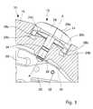
- the device shown in the drawingcomprises a support formed by a box of shows 10, a pusher 12 mounted movable in translation along an axis A-A on the box 10, and a spring element 14 interposed between the box 10 and the pusher 12.
- the box 10can be made of any solid material, for example made of metal or plastic. It has a middle part 16 and a bottom 17, which define a housing 18 in which is disposed a watch movement 20. In the watch described here, the base 17 forms the plate of the movement 20.
- the middle part 16is pierced with a cylindrical hole 22 whose axis, coincident with the axis A-A, is oriented radially, connecting the housing 18 outside the box 10.
- the middle part 16comprises on its external surface an elongated recess 24 whose side wall 24a is for example in the shape of an oval cylinder.
- the bottom of the recess 24has two opposite recesses 24b, adjacent to the wall 24a, and a curved central portion 24c having a shape of a spherical cap whose center is on the axis A-A pusher 12.
- the pusher 12comprises a cylindrical rod 26, preferably made of metal, engaged in the hole 22, and a head 28 advantageously made of plastic, fixed to the rod 26 by overmolding and disposed outside of the box 10.
- the rod 26has a diameter slightly less than that of hole 22, so that it can slide there freely. It is provided with two grooves 26a and 26b arranged so that, when the pusher 12 is in place, the groove 26a is inside the housing 18, flush with the inner wall of the middle part 16, and the groove 26b in the part median of hole 22.
- An O-ring 34disposed in the groove 26b, is in contact with the wall of the hole 22 all around, to seal the passage of the pusher 12 in the hole 22 of the middle 16.
- the head 28 of the pusher 12has an elongated shape which corresponds to that of the recess 24, so that it can slide there but without being able to rotate.
- She herehas a cap shape having a domed outer portion 28a, integral of the rod 26, and an oval cylindrical portion 28b extending from the outer portion towards the middle part 16, inside the recess 24.
- the head 28has a 28d concave inner surface in the shape of a truncated cone.
- the cylindrical portion 28bis provided, on its internal face, with two protrusions formed by fingers 28c extending respectively from the head to the interior of each recess 24b and of which the function will be specified later.
- Spring 14is formed from a thin sheet of stainless steel, shaped general oval and provided in its center with a round orifice 14a whose diameter is slightly higher than that of the rod 26, so that the latter can slide there freely.
- the oval shapehas a large axis B-B and a small axis C-C, these axes being perpendicular to each other and perpendicular to the axis A-A of hole 22.
- the sheet forming the spring 14is notched at the two ends of the major axis of the oval, to form cutouts 14b intended to receive the fingers 28c. She is curved or folded so as to have a shape inscribed on a surface geometric generated by a generator parallel to the longitudinal axis B-B, with a concave face 14c and a convex face 14d.
- the springhas a shape general roof which has two flat walls connected to each other by a portion rounded, thus forming a substantially V-shaped cross section.
- the springhas rotational symmetry about the axis A-A, thus that symmetry with respect to its median longitudinal plane passing through the axes A-A and B-B.
- the spring element 14is arranged in the recess 24, so that the rod 26 passes through the hole 14a when it is engaged in the hole 22 and its face concave 14c is in abutment against the head 28, on at least one pair of bearing zones 36 located near the ends of its oval shape, while its convex face 14d is in abutment against the central portion 24c of the support by at least one zone median 38 near the push rod.
- the spring element 14is positioned relative to the pusher 12 by the engagement of the fingers 28c in the cutouts 14b, so that it does not rub against the side wall 24a.
- the support zones of the spring 14 against the head 28are found along the edges of the cutouts 14b. In the initial position shown in Figure 1, there are in fact two of these support zones 36 on either side of each cutout 14b.
- the convex face of the central part of the spring 14bears against the box 10 on two median zones 38 located on either side of the orifice 14a.
- the spring 14behaves like a beam supported in its middle part and subjected to a force at its two ends.
- the beamtends to bend on the one hand in the direction of its length, but also to flatten in its transverse direction C-C because of the tensile stresses which act along its two edges parallel to B-B.
- the curved or V-shaped shape of the springtends to open.
- the arrangement of the spring and its bearing zonesis symmetrical with respect to its plane longitudinal median, the forces and deformations are also symmetrical and do not require no fixing means to stabilize the spring.
- the reaction force of the beamis a function of its deflection and the moment static inertia of its cross section.
- this moment of inertiais all the more high that the V is closed.
- the Vdeviates during the stroke of the pusher, which reduces the moment static inertia.
- the force necessary to make flexing the beamdecreases as the arrow increases.
- maintaining the pressurecauses a sudden push in of the pusher, which gives rise to the function of click.
- the leaf spring 30then suddenly comes into contact with the pin 32, thus ensuring the desired electrical contact.
- the transverse spacing between the two support zones 36 at each end of the spring 14also contributes to flattening the cross section thereof, but this effect complementary is not essential.
- the spring 14 described abovecan not only be made inexpensively, but also is very easy to assemble and does not require great robustness of the support, since the greatest force applied to it is the pressure on the pusher. If this pressure exceeds the maximum reactive force of the spring, it will be absorbed by the fingers 28c abutting the watch case.
- the spring elementcould be turned over if the bearing surfaces corresponding to the box and the pusher are reversed. Many others solutions are possible.
- the spring elementcould for example have a round or rectangular shape, or even have a left surface.
- the static moment of inertiamust decrease when the element is subjected to a bending. This condition is satisfied when the section of the element according to a plane defined by the axes A-A and C-C, which is perpendicular to the axis B-B along which flexion takes place, is curved in a rest position, i.e. when the element is not subjected to elastic deformation.
- the spring elementcould also be placed inside the box, or even in a housing made in the box and intended for this purpose. On the other hand, the spring element could be extended by one or more blades carrying out themselves the electrical contact in place of the leaf spring 30.
- the devicecould also be used for push buttons used in devices other than watches, such as phones or computers.
Landscapes
- Physics & Mathematics (AREA)
- General Physics & Mathematics (AREA)
- Push-Button Switches (AREA)
- Electric Clocks (AREA)
- Clamps And Clips (AREA)
- Telephone Function (AREA)
- Lock And Its Accessories (AREA)
- Electromechanical Clocks (AREA)
Abstract
Description
Translated fromFrenchLa présente invention se rapporte à un dispositif de commande à décliccomportant un support, un poussoir monté mobile sur le support de façon à avoir unecourse de translation selon un axe, et un élément à ressort capable d'exercer sur lepoussoir une force réactive qui passe par un maximum pendant la course dupoussoir. L'invention concerne aussi une montre comportant une boíte et un dispositifde commande de ce type.The present invention relates to a click control devicecomprising a support, a pusher mounted mobile on the support so as to have atranslational travel along an axis, and a spring element capable of exerting on thepush a reactive force which passes through a maximum during the stroke of thepusher. The invention also relates to a watch comprising a case and a deviceof this type.
Un tel dispositif de commande à déclic, dit aussi à action brusque, estutilisable en particulier pour actionner une lame de contact d'un interrupteurélectrique, notamment pour commander des fonctions d'un appareil électroniqueportable. Cependant le poussoir d'un tel dispositif peut aussi produire une commandepurement mécanique.Such a snap-action control device, also called a snap action, isusable in particular for actuating a contact blade of a switchelectric, in particular for controlling functions of an electronic deviceportable. However, the push-button of such a device can also produce a command.purely mechanical.
De tels dispositifs sont utilisés, par exemple, pour commander le départ etl'arrêt des montres chronographes mécaniques ou électriques. La fonction de déclicfait que le poussoir reste sans effet tant que la pression exercée ne dépasse pas unevaleur limite de la force réactive, puis cette limite étant dépassée, le dispositif changebrusquement d'état, car la pression nécessaire à terminer la fonction est inférieure àcette valeur limite. Il est ainsi possible de faire partir ou arrêter un compteur avecprécision.Such devices are used, for example, to control the start andstopping mechanical or electric chronograph watches. The click functioncauses the pusher to remain ineffective as long as the pressure exerted does not exceed onereactive force limit value, then this limit being exceeded, the device changesabruptly because the pressure required to complete the function is less thanthis limit value. It is thus possible to start or stop a counter withprecision.
Dans de telles montres connues, les pièces assurant la fonction de déclic fontd'habitude partie du mécanisme de chronographe et sont fixées sur un pont ou sur laplatine du mouvement. La force à vaincre est engendrée par un dispositif de typesautoir, avec un ressort travaillant en flexion, qui coopère avec une came, comme leprévoit par exemple le brevet CH 642 220. Les dispositifs de ce type nécessitent unvolume important, ce qui est un lourd handicap dans une montre.In such known watches, the parts ensuring the click function makeusually part of the chronograph mechanism and are fixed on a bridge or on themovement plate. The force to be overcome is generated by a device of the typelong necklace, with a spring working in flexion, which cooperates with a cam, like theprovides for example the patent CH 642 220. Devices of this type require alarge volume, which is a serious handicap in a watch.
Il a également été proposé de réaliser des poussoirs à déclic dans lesquelscette fonction est assurée par un élément à ressort monté sur la boíte ou le poussoir.Une solution de cet ordre est représentée dans le brevet CH 629 647. Dans cedocument, l'élément à ressort est réalisé au moyen d'une pièce annulaire, déformableradialement, qui glisse sur une surface de came et franchit une bosse de cettesurface. Une telle solution nécessite peu de place, mais il est difficile de maítriser lepoint de déclic et la force à appliquer pour assurer la fonction.It has also been proposed to produce click pushers in whichthis function is provided by a spring element mounted on the box or the pusher.A solution of this order is represented in patent CH 629 647. In thisdocument, the spring element is produced by means of an annular, deformable partradially, which slides on a cam surface and crosses a bump of thisarea. Such a solution requires little space, but it is difficult to control theclick point and the force to be applied to ensure the function.
On connaít par ailleurs, dans le domaine spécifique des interrupteursélectriques, des dispositifs de commande utilisant des ressorts à déclic pour produireune action brusque. Un type de ressort à déclic peu encombrant, illustré par exemple dans le brevet US 4 234 769, est formé par une lame flexible droite qui est maintenuecourbée longitudinalement par compression entre deux butées fixes. Toutefois ceressort a deux positions stables et, dans une commande par bouton-poussoir, celanécessite un ressort de rappel supplémentaire. Un autre inconvénient est que lacompression permanente exige un support assez robuste qui peut constituer unélément gênant dans un petit appareil tel qu'une montre.We also know, in the specific field of switcheselectrical, control devices using snap springs to producesudden action. A space-saving type of snap spring, illustrated for examplein US Patent 4,234,769, is formed by a straight flexible blade which is heldcurved longitudinally by compression between two fixed stops. However thisspring has two stable positions and, in a push button control, thisrequires an additional return spring. Another disadvantage is that thepermanent compression requires a fairly robust support which can constitute aannoying element in a small device such as a watch.
On peut pallier en partie ces inconvénients en incorporant la lame courbée parcompression dans une lame-ressort plus grande qui forme un cadre autour d'elle etqui sera elle-même fléchie par le poussoir, par exemple comme le montre le brevetUS 5 075 524. Ce système nécessite toutefois une course relativement grande dupoussoir et s'avère donc trop encombrant dans un appareil aussi petit qu'une montre.En outre, la fixation de cet élément à ressort exige aussi un support robuste et uncertain encombrement.These disadvantages can be partially overcome by incorporating the curved bladecompression in a larger leaf spring which forms a frame around it andwhich will itself be bent by the pusher, for example as shown in the patentUS 5,075,524. However, this system requires a relatively large stroke of thepush button and is therefore too bulky in a device as small as a watch.In addition, fixing this spring element also requires a sturdy support and asome bulk.
Un but de la présente invention est de réaliser un dispositif de commande àdéclic simple et peu encombrant. A titre additionnel, le dispositif devrait être facile àfabriquer et à monter et fiable en fonctionnement.An object of the present invention is to provide a control device withsimple and space-saving click. Additionally, the device should be easy tomanufacture and assemble and reliable in operation.
Dans ce but, la présente invention concerne, selon un premier aspect, undispositif de commande à déclic du genre indiqué en préambule, caractérisé en ceque l'élément à ressort comporte une feuille allongée en matériau élastique,interposée entre le poussoir et le support et ayant au moins une zone médianedisposée dans sa partie centrale et au moins une paire de zones d'appui situées auxextrémités de ladite feuille, la paire de zones d'appui et la zone médiane étantdestinées à s'appuyer l'une contre le poussoir et l'autre contre le support de sorte quela course du poussoir tend à fléchir longitudinalement ladite feuille, et en ce que laditefeuille présente au repos une section transversale incurvée ou en forme de V.To this end, the present invention relates, according to a first aspect, to aclick-type control device of the type indicated in the preamble, characterized inthat the spring element comprises an elongated sheet of elastic material,interposed between the pusher and the support and having at least one central zonearranged in its central part and at least one pair of support zones located at theends of said sheet, the pair of support zones and the central zone beingintended to rest one against the pusher and the other against the support so thatthe stroke of the pusher tends to flex longitudinally said sheet, and in that saidleaf has at rest a curved or V-shaped cross section
Un avantage de cet agencement est que l'élément à ressort n'a pas besoind'être fixé rigidement au support, lequel ne doit donc pas être particulièrementrobuste. Il suffit que les zones d'appui de l'élément à ressort soient maintenues auxemplacements corrects, par exemple par le poussoir ou grâce à un logement danslequel cet élément est librement emboíté. En fait, l'élément à ressort n'a besoin d'êtrefixé ni au support, ni au poussoir. Un autre avantage est qu'un tel élément peut êtretrès petit, notamment pas plus grand que la tête du poussoir, et qu'on peut fabriqueret monter l'ensemble du dispositif à un prix très bas.An advantage of this arrangement is that the spring element does not needto be rigidly attached to the support, which should therefore not be particularlyrobust. It suffices that the bearing areas of the spring element are maintained at thecorrect locations, for example by the pusher or by a housing inwhich this element is freely fitted. In fact, the spring element does not need to befixed neither to the support nor to the pusher. Another advantage is that such an element can bevery small, especially no larger than the pusher head, and which can be producedand mount the entire device at a very low price.
De préférence, afin d'assurer de bonnes conditions de travail du poussoir et del'élément à ressort, ce dernier comporte, dans sa partie centrale, un orifice à traverslequel passe une tige du poussoir.Preferably, in order to ensure good working conditions for the pusher andthe spring element, the latter comprises, in its central part, an orifice throughwhich passes a rod of the pusher.
Dans un mode de réalisation préféré, ladite paire de zones d'appui est situéesur une face concave, et la zone médiane sur une face convexe de l'élément àressort. De manière avantageuse, le support est en appui contre la face concave et lepoussoir contre la face convexe.In a preferred embodiment, said pair of support zones is locatedon a concave face, and the middle zone on a convex face of the element tospring. Advantageously, the support is in abutment against the concave face and thepush against the convex face.
Pour garantir que les conditions de travail restent les mêmes au cours de la viedu produit, il est souhaitable que l'élément à ressort soit positionné par rapport ausupport et au poussoir. Il comporte, à cet effet, des découpes au voisinage de sesextrémités opposées en contact avec le poussoir. En outre, ce dernier est muni deprotubérances engagées dans ces découpes pour assurer le positionnement relatif del'élément à ressort et du poussoir. Le poussoir lui-même peut être guidé de manièreclassique par rapport au support.To ensure that working conditions remain the same throughout lifeof the product, it is desirable that the spring element is positioned relative to thesupport and push button. To this end, it includes cutouts in the vicinity of itsopposite ends in contact with the pusher. In addition, the latter is provided withprotrusions engaged in these cutouts to ensure the relative positioning ofthe spring element and the pusher. The pusher itself can be guided in a wayclassic compared to the support.
De bonnes conditions de fabrication ont été obtenues lorsque la forme del'élément à ressort comporte deux parois planes reliées entre elles par une portionarrondie. Cette structure permet, en outre, de garantir un déclic net et de bienmaítriser la force à appliquer, de manière à ce que, pour un même modèle, elle soitpratiquement la même d'une pièce à l'autre.Good manufacturing conditions have been obtained when the form ofthe spring element has two flat walls connected to each other by a portionrounded. This structure also makes it possible to guarantee a clear click and goodcontrol the force to be applied, so that, for the same model, it ispractically the same from one room to another.
La présente invention se rapporte également à une montre munie d'une boíteet d'un dispositif de commande tel que défini plus haut. Dans cette montre, la boíteforme le support du dispositif de commande, le poussoir comporte une tête disposéeà l'extérieur de la boíte et une tige engagée dans un trou de la boíte et débouchant àl'intérieur de cette dernière. L'élément à ressort est disposé dans un évidement d'uneface extérieure de la boíte et coopère avec la tête du poussoir.The present invention also relates to a watch fitted with a boxand a control device as defined above. In this watch, the boxforms the support for the control device, the pusher has a head arrangedoutside of the box and a rod engaged in a hole in the box and opening outinside the latter. The spring element is arranged in a recess of aouter face of the box and cooperates with the head of the pusher.
L'épaisseur des montres joue un rôle important du point de vue esthétique.Aussi, afin de réduire cette épaisseur autant que possible tout en ayant des poussoirsfaciles à manipuler, tant la tête du poussoir que l'élément à ressort du dispositif decommande peuvent être de forme allongée, de préférence ovale.The thickness of the watches plays an important role from an aesthetic point of view.Also, in order to reduce this thickness as much as possible while having pusherseasy to handle, both the pusher head and the spring element of thecontrol can be elongated, preferably oval.
D'autres avantages et caractéristiques de l'invention ressortiront de ladescription suivante d'un mode de réalisation préféré, en référence aux dessinsannexés dans lesquels :
Le dispositif représenté au dessin comporte un support formé d'une boíte demontre 10, un poussoir 12 monté mobile en translation selon un axe A-A sur la boíte10, et un élément à ressort 14 interposé entre la boíte 10 et le poussoir 12.The device shown in the drawing comprises a support formed by a box of
La boíte 10 peut être réalisée en n'importe quel matériau solide, par exempleen métal ou en plastique. Elle comporte une carrure 16 et un fond 17, qui définissentun logement 18 dans lequel est disposé un mouvement de montre 20. Dans la montredécrite ici, le fond 17 forme la platine du mouvement 20. La carrure 16 est percée d'untrou cylindrique 22 dont l'axe, confondu avec l'axe A-A, est orienté radialement, reliantle logement 18 à l'extérieur de la boíte 10. Au voisinage du trou 22, la carrure 16comprend sur sa surface externe un évidement allongé 24 dont la paroi latérale 24aest par exemple en forme de cylindre ovale. Le fond de l'évidement 24 comporte deuxrenfoncements opposés 24b, adjacents à la paroi 24a, et une portion centrale bombée24c présentant une forme de calotte sphérique dont le centre se trouve sur l'axe A-Adu poussoir 12.The
Le poussoir 12 comporte une tige cylindrique 26, de préférence en métal,engagée dans le trou 22, et une tête 28 avantageusement en plastique, fixée à la tige26 par surmoulage et disposée à l'extérieur de la boíte 10. La tige 26 présente undiamètre légèrement inférieur à celui du trou 22, de façon qu'elle puisse y coulisserlibrement. Elle est munie de deux gorges 26a et 26b disposées de manière que,lorsque le poussoir 12 est en place, la gorge 26a se trouve à l'intérieur du logement18, affleurant la paroi intérieure de la carrure 16, et la gorge 26b dans la partiemédiane du trou 22.The
Un ressort-lame 30, faisant partie d'une pièce métallique 29 fixée sur lemouvement et reliée à l'un des pôles de la pile électrique alimentant le mouvement20, comporte une échancrure 31 pour s'engager dans la gorge 26a et empêcher ainsile poussoir 12 d'être retiré du trou 22. Il assure en outre une fonction de contactélectrique, son extrémité libre allant s'appliquer contre une goupille 32 d'une carte àcircuits imprimés 33 fixée au fond 17, lorsque le poussoir 12 est pressé suffisamment,comme on l'expliquera plus loin.A
Un joint torique 34, disposé dans la gorge 26b, est en contact avec la paroi dutrou 22 sur tout son pourtour, pour assurer l'étanchéité du passage du poussoir 12dans le trou 22 de la carrure 16.An O-
La tête 28 du poussoir 12 a une forme allongée qui correspond à celle del'évidement 24, de sorte qu'elle peut y coulisser mais sans pouvoir tourner. Elleprésente ici une forme de calotte ayant une portion extérieure bombée 28a, solidairede la tige 26, et une portion cylindrique ovale 28b s'étendant de la portion extérieureen direction de la carrure 16, à l'intérieur de l'évidement 24. La tête 28 présente unesurface intérieure concave 28d en forme de tronc de cône. La portion cylindrique 28best munie, sur sa face interne, de deux protubérances formées par des doigts 28c s'étendant respectivement de la tête à l'intérieur de chaque renfoncement 24b et dontla fonction sera précisée plus loin.The
Le ressort 14 est formé d'une feuille mince d'acier inoxydable, de formegénérale ovale et munie en son centre d'un orifice rond 14a dont le diamètre estlégèrement supérieur à celui de la tige 26, de manière à ce que cette dernière puissey coulisser librement. La forme ovale a un grand axe B-B et un petit axe C-C, cesaxes étant perpendiculaires entre eux et perpendiculaires à l'axe A-A du trou 22.
La feuille formant le ressort 14 est entaillée aux deux extrémités du grand axede l'ovale, pour former des découpes 14b destinées recevoir les doigts 28c. Elle estincurvée ou pliée de manière à présenter une forme inscrite sur une surfacegéométrique engendrée par une génératrice parallèle à l'axe longitudinal B-B, avecune face concave 14c et une face convexe 14d.The sheet forming the
Dans le mode de réalisation représenté au dessin, le ressort a une formegénérale en toit qui présente deux parois planes reliées entre elles par une portionarrondie, formant ainsi une section transversale sensiblement en forme de V. Onrelèvera que le ressort présente une symétrie de rotation autour de l'axe A-A, ainsiqu'une symétrie par rapport à son plan longitudinal médian passant par les axes A-Aet B-B.In the embodiment shown in the drawing, the spring has a shapegeneral roof which has two flat walls connected to each other by a portionrounded, thus forming a substantially V-shaped cross section.will note that the spring has rotational symmetry about the axis A-A, thusthat symmetry with respect to its median longitudinal plane passing through the axes A-Aand B-B.
L'élément à ressort 14 est disposé dans l'évidement 24, de manière que la tige26 le traverse par l'orifice 14a lorsqu'elle est engagée dans le trou 22 et que sa faceconcave 14c soit en appui contre la tête 28, sur au moins une paire de zones d'appui36 situées à proximité des extrémités de sa forme ovale, tandis que sa face convexe14d est en appui contre la portion centrale 24c du support par au moins une zonemédiane 38 à proximité de la tige du poussoir. L'élément à ressort 14 est positionnérelativement au poussoir 12 par l'engagement des doigts 28c dans les découpes 14b,de sorte qu'il ne frotte pas contre la paroi latérale 24a.The
Dans l'exemple représenté, les zones d'appui du ressort 14 contre la tête 28 setrouvent le long des bords des découpes 14b. Dans la position initiale représentée enfigure 1, il y a en fait deux de ces zones d'appui 36 de part et d'autre de chaquedécoupe 14b. La face convexe de la partie centrale du ressort 14 s'appuie contre laboíte 10 sur deux zones médianes 38 situées de part et d'autre de l'orifice 14a.In the example shown, the support zones of the
Lorsque l'utilisateur d'une montre munie d'un dispositif tel que décrit plus hautactionne le poussoir 12, il exerce sur la tête 28 une pression manuelle qui tend à fairepénétrer la tige 26 à l'intérieur de la boíte 10. La tête 28 prend appui, au voisinage deses doigts 28c, contre la face concave 14c du ressort 14, plus précisément sur lesdeux paires de zones d'appui 36 situés aux extrémités du ressort 14, dont les zones médianes 38 sont en appui contre la portion centrale 24c bombée du logement 24. Lapression engendre ainsi une force qui tend à déformer le ressort 14.When the user of a watch fitted with a device as described aboveactuates the
De la sorte, le ressort 14 se comporte comme une poutre appuyée dans sapartie médiane et soumise à une force à ses deux extrémités. Sous l'effet de lapression manuelle sur le poussoir, la poutre tend à fléchir d'une part dans le sens desa longueur, mais aussi à s'aplatir dans sa direction transversale C-C à cause descontraintes de traction qui agissent le long de ses deux bords parallèlement à B-B.Autrement dit, la forme incurvée ou en V du ressort tend à s'ouvrir. Comme ladisposition du ressort et de ses zones d'appui est symétrique par rapport à son planlongitudinal médian, les efforts et les déformations sont également symétriques et nenécessitent aucun moyen de fixation pour stabiliser le ressort.In this way, the
La force de réaction de la poutre est fonction de sa flèche et du momentd'inertie statique de sa section transversale. Or, ce moment d'inertie est d'autant plusélevé que le V est fermé. En d'autres termes, en soumettant la poutre à une forcesuffisante, le V s'écarte durant la course du poussoir, ce qui diminue le momentd'inertie statique. Il arrive un moment au-delà duquel la force nécessaire pour fairefléchir la poutre diminue lorsque la flèche augmente. Passé ce point, le maintien de lapression provoque un enfoncement brutal du poussoir, ce qui engendre la fonction dedéclic. Le ressort-lame 30 entre alors brusquement en contact avec la goupille 32,assurant ainsi le contact électrique voulu.The reaction force of the beam is a function of its deflection and the momentstatic inertia of its cross section. However, this moment of inertia is all the morehigh that the V is closed. In other words, by subjecting the beam to a forcesufficient, the V deviates during the stroke of the pusher, which reduces the momentstatic inertia. There comes a time beyond which the force necessary to makeflexing the beam decreases as the arrow increases. After this point, maintaining thepressure causes a sudden push in of the pusher, which gives rise to the function ofclick. The
L'espacement transversal entre les deux zones d'appui 36 à chaque extrémitédu ressort 14 contribue aussi à aplatir la section transversale de celui-ci, mais cet effetcomplémentaire n'est pas indispensable.The transverse spacing between the two
En relâchant le poussoir, celui-ci revient seul à sa place, sous l'actionconjuguée du ressort 14 et du ressort-lame 30. Comme le ressort 14 fournit une forcede rappel sur toute la course du poussoir, la force du ressort-lame 30 n'est pasindispensable. Ce dernier pourrait aussi être rappelé par le ressort 14 par l'entremisede la tige 26.By releasing the pusher, it returns to its place alone, under the actionconjugate of the
Des essais effectués ont montré qu'avec un ressort 14 réalisé à partir d'unetôle de 0,06 mm d'épaisseur, ayant une largeur de 3,50 mm, une longueur active de5,00 mm (définie par la distance entre les deux découpes 14b), un trou central 14a de1,40 mm de diamètre et une ouverture du V égale à 140°, la force à appliquer sur lepoussoir est égale à environ 7 N.Tests carried out have shown that with a
On comprend aisément que le ressort 14 décrit ci-dessus peut non seulementêtre fabriqué à peu de frais, mais aussi est très facile à monter et ne nécessite pasune grande robustesse du support, puisque la plus grande force qui lui est appliquée est la pression sur le poussoir. Si cette pression dépasse la force réactive maximaledu ressort, elle sera absorbée par les doigts 28c butant contre la boíte de montre.It is easily understood that the
Il est bien évident que le mode de réalisation décrit n'est qu'une variante parmid'autres. L'élément à ressort pourrait être retourné si les surfaces d'appuicorrespondantes de la boíte et du poussoir sont inversées. De nombreuses autressolutions sont envisageables. L'élément à ressort pourrait par exemple avoir uneforme ronde ou rectangulaire, ou encore présenter une surface gauche. Dans tous lescas, il faut que le moment d'inertie statique diminue lorsque l'élément est soumis àune flexion. Cette condition est satisfaite lorsque la section de l'élément selon un plandéfini par les axes A-A et C-C, qui est perpendiculaire à l'axe B-B le long duquels'effectue la flexion, est incurvée dans une position de repos, c'est-à-dire quandl'élément n'est pas soumis à une déformation élastique.It is obvious that the embodiment described is only one variant amongothers. The spring element could be turned over if the bearing surfacescorresponding to the box and the pusher are reversed. Many otherssolutions are possible. The spring element could for example have around or rectangular shape, or even have a left surface. In all thecase, the static moment of inertia must decrease when the element is subjected toa bending. This condition is satisfied when the section of the element according to a planedefined by the axes A-A and C-C, which is perpendicular to the axis B-B along whichflexion takes place, is curved in a rest position, i.e. whenthe element is not subjected to elastic deformation.
L'élément à ressort pourrait également être disposé à l'intérieur de la boíte,voire dans un logement pratiqué dans la boíte et destiné à cet effet. D'autre part,l'élément à ressort pourrait être prolongé par une ou plusieurs lames réalisant elles-mêmesle contact électrique à la place du ressort-lame 30.The spring element could also be placed inside the box,or even in a housing made in the box and intended for this purpose. On the other hand,the spring element could be extended by one or more blades carrying out themselvesthe electrical contact in place of the
Le dispositif pourrait également être utilisé pour des boutons-poussoirs utilisésdans d'autres appareils que les montres, par exemple des téléphones ou desordinateurs.The device could also be used for push buttons usedin devices other than watches, such as phones orcomputers.
Claims (10)
Translated fromFrenchPriority Applications (4)
| Application Number | Priority Date | Filing Date | Title |
|---|---|---|---|
| DE60044023TDE60044023D1 (en) | 2000-06-07 | 2000-06-07 | Snap action actuator and clock equipped with such a device |
| EP00202007AEP1162521B1 (en) | 2000-06-07 | 2000-06-07 | Snap-action actuating device and watch provided with such a device |
| ES00202007TES2340355T3 (en) | 2000-06-07 | 2000-06-07 | RATCHET CONTROL AND WATCH DEVICE PROVIDED WITH SUCH DEVICE. |
| AT00202007TATE461472T1 (en) | 2000-06-07 | 2000-06-07 | ACTUATING DEVICE WITH SNAP EFFECT AND WATCH EQUIPPED WITH SUCH DEVICE |
Applications Claiming Priority (1)
| Application Number | Priority Date | Filing Date | Title |
|---|---|---|---|
| EP00202007AEP1162521B1 (en) | 2000-06-07 | 2000-06-07 | Snap-action actuating device and watch provided with such a device |
Publications (2)
| Publication Number | Publication Date |
|---|---|
| EP1162521A1true EP1162521A1 (en) | 2001-12-12 |
| EP1162521B1 EP1162521B1 (en) | 2010-03-17 |
Family
ID=8171608
Family Applications (1)
| Application Number | Title | Priority Date | Filing Date |
|---|---|---|---|
| EP00202007AExpired - LifetimeEP1162521B1 (en) | 2000-06-07 | 2000-06-07 | Snap-action actuating device and watch provided with such a device |
Country Status (4)
| Country | Link |
|---|---|
| EP (1) | EP1162521B1 (en) |
| AT (1) | ATE461472T1 (en) |
| DE (1) | DE60044023D1 (en) |
| ES (1) | ES2340355T3 (en) |
Cited By (4)
| Publication number | Priority date | Publication date | Assignee | Title |
|---|---|---|---|---|
| FR2851845A1 (en)* | 2003-02-27 | 2004-09-03 | Itt Mfg Enterprises Inc | SWITCHING DEVICE THAT CAN BE EQUIPPED WITH A CENTRAL LIGHT SOURCE, AND KEYBOARD KEY OF AN ELECTRICAL DEVICE COMPRISING SUCH A SWITCHING DEVICE. |
| EP1589552A1 (en)* | 2004-04-21 | 2005-10-26 | Hosiden Corporation | Push-on Switch |
| CN100501890C (en)* | 2004-04-21 | 2009-06-17 | 星电株式会社 | push on switch |
| EP4092490A1 (en)* | 2021-05-19 | 2022-11-23 | Meco S.A. | Device for controlling a timepiece movement with touch return and timepiece, in particular a watch, including such a device |
Citations (7)
| Publication number | Priority date | Publication date | Assignee | Title |
|---|---|---|---|---|
| FR1157462A (en)* | 1956-08-24 | 1958-05-29 | Jaeger Ets Ed | Maneuvering device with sudden release |
| DE2360167A1 (en)* | 1973-12-03 | 1975-06-05 | Marquardt J & J | Snap-action push-button switch - has moving contact arm with snap-action leaf spring between two support bearings |
| US3928741A (en)* | 1974-09-16 | 1975-12-23 | Texas Instruments Inc | Momentary contact single pole switch |
| FR2335930A1 (en)* | 1975-12-20 | 1977-07-15 | Telefonbau & Normalzeit Gmbh | Electrical pushbutton switch for romote control system - has deflecting strip making contact with printed circuit conductors |
| US4234769A (en) | 1978-02-22 | 1980-11-18 | Aktieselskabet Mec Mekanisk Elektrisk Compagni Af 1975 | Electrical switch having a floating bridge member |
| CH629647GA3 (en) | 1978-03-24 | 1982-05-14 | ||
| US5075524A (en) | 1989-08-30 | 1991-12-24 | Stocko Metallwarenfabriken Henkels Und Sohn Gmbh & Co. | Electric pushbutton switch |
- 2000
- 2000-06-07EPEP00202007Apatent/EP1162521B1/ennot_activeExpired - Lifetime
- 2000-06-07ESES00202007Tpatent/ES2340355T3/ennot_activeExpired - Lifetime
- 2000-06-07ATAT00202007Tpatent/ATE461472T1/ennot_activeIP Right Cessation
- 2000-06-07DEDE60044023Tpatent/DE60044023D1/ennot_activeExpired - Lifetime
Patent Citations (7)
| Publication number | Priority date | Publication date | Assignee | Title |
|---|---|---|---|---|
| FR1157462A (en)* | 1956-08-24 | 1958-05-29 | Jaeger Ets Ed | Maneuvering device with sudden release |
| DE2360167A1 (en)* | 1973-12-03 | 1975-06-05 | Marquardt J & J | Snap-action push-button switch - has moving contact arm with snap-action leaf spring between two support bearings |
| US3928741A (en)* | 1974-09-16 | 1975-12-23 | Texas Instruments Inc | Momentary contact single pole switch |
| FR2335930A1 (en)* | 1975-12-20 | 1977-07-15 | Telefonbau & Normalzeit Gmbh | Electrical pushbutton switch for romote control system - has deflecting strip making contact with printed circuit conductors |
| US4234769A (en) | 1978-02-22 | 1980-11-18 | Aktieselskabet Mec Mekanisk Elektrisk Compagni Af 1975 | Electrical switch having a floating bridge member |
| CH629647GA3 (en) | 1978-03-24 | 1982-05-14 | ||
| US5075524A (en) | 1989-08-30 | 1991-12-24 | Stocko Metallwarenfabriken Henkels Und Sohn Gmbh & Co. | Electric pushbutton switch |
Cited By (7)
| Publication number | Priority date | Publication date | Assignee | Title |
|---|---|---|---|---|
| FR2851845A1 (en)* | 2003-02-27 | 2004-09-03 | Itt Mfg Enterprises Inc | SWITCHING DEVICE THAT CAN BE EQUIPPED WITH A CENTRAL LIGHT SOURCE, AND KEYBOARD KEY OF AN ELECTRICAL DEVICE COMPRISING SUCH A SWITCHING DEVICE. |
| WO2004077474A1 (en)* | 2003-02-27 | 2004-09-10 | Itt Manufacturing Enterprises Inc. | A switch device capable of being fitted with a central light source, and a keypad key for electrical equipment including such a switch device |
| EP1589552A1 (en)* | 2004-04-21 | 2005-10-26 | Hosiden Corporation | Push-on Switch |
| US6995324B2 (en) | 2004-04-21 | 2006-02-07 | Hosiden Corporation | Push-on switch |
| CN100501890C (en)* | 2004-04-21 | 2009-06-17 | 星电株式会社 | push on switch |
| EP4092490A1 (en)* | 2021-05-19 | 2022-11-23 | Meco S.A. | Device for controlling a timepiece movement with touch return and timepiece, in particular a watch, including such a device |
| US12124219B2 (en) | 2021-05-19 | 2024-10-22 | Meco Sa | Device for controlling a horological movement with tactile feedback and timepiece, in particular a watch, comprising such a device |
Also Published As
| Publication number | Publication date |
|---|---|
| EP1162521B1 (en) | 2010-03-17 |
| ES2340355T3 (en) | 2010-06-02 |
| ATE461472T1 (en) | 2010-04-15 |
| DE60044023D1 (en) | 2010-04-29 |
Similar Documents
| Publication | Publication Date | Title |
|---|---|---|
| EP0001031B1 (en) | Push button switch with snap action | |
| EP0570647B1 (en) | Switch latch for a circuit breaker and circuit breakers incorporating it | |
| FR2865492A1 (en) | Locking assembly for locking e.g. door with tractor, has plastic operating unit with stop block movable with stop arm, from engaged to disengaged position, where block in engaged position maintains plastic rotor in locked position | |
| EP0823065B1 (en) | Resilient hinge for spectacles | |
| FR2513434A1 (en) | MECHANISM WITH INJURY TRIPPING, IN PARTICULAR FOR SWITCH | |
| EP0302070B1 (en) | Miniature switch with sudden break | |
| EP1162521B1 (en) | Snap-action actuating device and watch provided with such a device | |
| FR2503444A1 (en) | SUSPENDED RUPTURE SWITCH | |
| FR2460536A1 (en) | MULTIPLE SELECTIVE SWITCH, IN PARTICULAR FOR MOTOR VEHICLES | |
| FR2565730A1 (en) | Rocker operated push button electric switch | |
| EP0498212B1 (en) | Push-button mechanism for a timepiece | |
| FR2489702A1 (en) | SWITCH OPERATED BY A BALL ROLLING ON IT AND ITS APPLICATION IN AN ELECTRIC BILLIARD | |
| CH648953A5 (en) | ELECTRIC SWITCH WITH PREARMED CONTACT SPRING. | |
| FR3114436A1 (en) | Set of parts allowing the realization of a switch | |
| EP0403329A1 (en) | Circuit breaker with automatic tripping, particularly protective switch and fault-current protective switch | |
| EP4388569B1 (en) | Manual control device with a toroidal element for returning the control button | |
| EP0246131B1 (en) | Electrical bistable commutating device | |
| EP3685234B1 (en) | Device for controlling at least one electronic function of a portable object | |
| EP1670009B1 (en) | Operation mechanism for a multipole switch | |
| EP0130861B1 (en) | Tumbler switch | |
| CH686020B5 (en) | A control device has push-button switch. | |
| EP1170764B1 (en) | Push switch | |
| CH704691A1 (en) | Push button system for actuating functional actuating member placed inside case of e.g. electronic watch, has complementary guiding member connecting case and button head so as to partially resume operating efforts of system | |
| CH714517A2 (en) | Device for controlling at least one electronic function of a portable object | |
| CH695076A5 (en) | Push-push switch e.g. two-way switch, has interlocking unit defining, at rest, centered position of sheave relative to actuation finger, and having excrescences, on sheave, that engage in respective recesses provided on finger, at rest |
Legal Events
| Date | Code | Title | Description |
|---|---|---|---|
| PUAI | Public reference made under article 153(3) epc to a published international application that has entered the european phase | Free format text:ORIGINAL CODE: 0009012 | |
| AK | Designated contracting states | Kind code of ref document:A1 Designated state(s):AT BE CH CY DE DK ES FI FR GB GR IE IT LI LU MC NL PT SE | |
| AX | Request for extension of the european patent | Free format text:AL;LT;LV;MK;RO;SI | |
| 17P | Request for examination filed | Effective date:20020612 | |
| AKX | Designation fees paid | Free format text:AT BE CH CY DE DK ES FI FR GB GR IE IT LI LU MC NL PT SE | |
| RAP1 | Party data changed (applicant data changed or rights of an application transferred) | Owner name:ETA SA MANUFACTURE HORLOGERE SUISSE | |
| 17Q | First examination report despatched | Effective date:20080625 | |
| GRAP | Despatch of communication of intention to grant a patent | Free format text:ORIGINAL CODE: EPIDOSNIGR1 | |
| GRAS | Grant fee paid | Free format text:ORIGINAL CODE: EPIDOSNIGR3 | |
| GRAA | (expected) grant | Free format text:ORIGINAL CODE: 0009210 | |
| AK | Designated contracting states | Kind code of ref document:B1 Designated state(s):AT BE CH CY DE DK ES FI FR GB GR IE IT LI LU MC NL PT SE | |
| REG | Reference to a national code | Ref country code:GB Ref legal event code:FG4D Free format text:NOT ENGLISH | |
| REG | Reference to a national code | Ref country code:CH Ref legal event code:EP | |
| REG | Reference to a national code | Ref country code:IE Ref legal event code:FG4D | |
| REG | Reference to a national code | Ref country code:CH Ref legal event code:NV Representative=s name:ICB INGENIEURS CONSEILS EN BREVETS SA | |
| REF | Corresponds to: | Ref document number:60044023 Country of ref document:DE Date of ref document:20100429 Kind code of ref document:P | |
| REG | Reference to a national code | Ref country code:ES Ref legal event code:FG2A Ref document number:2340355 Country of ref document:ES Kind code of ref document:T3 | |
| REG | Reference to a national code | Ref country code:NL Ref legal event code:VDEP Effective date:20100317 | |
| PGFP | Annual fee paid to national office [announced via postgrant information from national office to epo] | Ref country code:ES Payment date:20100611 Year of fee payment:11 | |
| PG25 | Lapsed in a contracting state [announced via postgrant information from national office to epo] | Ref country code:FI Free format text:LAPSE BECAUSE OF FAILURE TO SUBMIT A TRANSLATION OF THE DESCRIPTION OR TO PAY THE FEE WITHIN THE PRESCRIBED TIME-LIMIT Effective date:20100317 | |
| PGFP | Annual fee paid to national office [announced via postgrant information from national office to epo] | Ref country code:AT Payment date:20100521 Year of fee payment:11 | |
| REG | Reference to a national code | Ref country code:IE Ref legal event code:FD4D | |
| PG25 | Lapsed in a contracting state [announced via postgrant information from national office to epo] | Ref country code:SE Free format text:LAPSE BECAUSE OF FAILURE TO SUBMIT A TRANSLATION OF THE DESCRIPTION OR TO PAY THE FEE WITHIN THE PRESCRIBED TIME-LIMIT Effective date:20100317 Ref country code:NL Free format text:LAPSE BECAUSE OF FAILURE TO SUBMIT A TRANSLATION OF THE DESCRIPTION OR TO PAY THE FEE WITHIN THE PRESCRIBED TIME-LIMIT Effective date:20100317 Ref country code:GR Free format text:LAPSE BECAUSE OF FAILURE TO SUBMIT A TRANSLATION OF THE DESCRIPTION OR TO PAY THE FEE WITHIN THE PRESCRIBED TIME-LIMIT Effective date:20100618 Ref country code:CY Free format text:LAPSE BECAUSE OF FAILURE TO SUBMIT A TRANSLATION OF THE DESCRIPTION OR TO PAY THE FEE WITHIN THE PRESCRIBED TIME-LIMIT Effective date:20100317 | |
| PGFP | Annual fee paid to national office [announced via postgrant information from national office to epo] | Ref country code:GB Payment date:20100527 Year of fee payment:11 | |
| BERE | Be: lapsed | Owner name:ETA SA MANUFACTURE HORLOGERE SUISSE Effective date:20100630 | |
| PLBE | No opposition filed within time limit | Free format text:ORIGINAL CODE: 0009261 | |
| STAA | Information on the status of an ep patent application or granted ep patent | Free format text:STATUS: NO OPPOSITION FILED WITHIN TIME LIMIT | |
| PG25 | Lapsed in a contracting state [announced via postgrant information from national office to epo] | Ref country code:PT Free format text:LAPSE BECAUSE OF FAILURE TO SUBMIT A TRANSLATION OF THE DESCRIPTION OR TO PAY THE FEE WITHIN THE PRESCRIBED TIME-LIMIT Effective date:20100719 Ref country code:IE Free format text:LAPSE BECAUSE OF FAILURE TO SUBMIT A TRANSLATION OF THE DESCRIPTION OR TO PAY THE FEE WITHIN THE PRESCRIBED TIME-LIMIT Effective date:20100317 Ref country code:DK Free format text:LAPSE BECAUSE OF FAILURE TO SUBMIT A TRANSLATION OF THE DESCRIPTION OR TO PAY THE FEE WITHIN THE PRESCRIBED TIME-LIMIT Effective date:20100317 Ref country code:MC Free format text:LAPSE BECAUSE OF NON-PAYMENT OF DUE FEES Effective date:20100630 | |
| 26N | No opposition filed | Effective date:20101220 | |
| PG25 | Lapsed in a contracting state [announced via postgrant information from national office to epo] | Ref country code:BE Free format text:LAPSE BECAUSE OF NON-PAYMENT OF DUE FEES Effective date:20100630 | |
| GBPC | Gb: european patent ceased through non-payment of renewal fee | Effective date:20110607 | |
| PG25 | Lapsed in a contracting state [announced via postgrant information from national office to epo] | Ref country code:AT Free format text:LAPSE BECAUSE OF NON-PAYMENT OF DUE FEES Effective date:20110607 | |
| REG | Reference to a national code | Ref country code:AT Ref legal event code:MM01 Ref document number:461472 Country of ref document:AT Kind code of ref document:T Effective date:20110607 | |
| PG25 | Lapsed in a contracting state [announced via postgrant information from national office to epo] | Ref country code:GB Free format text:LAPSE BECAUSE OF NON-PAYMENT OF DUE FEES Effective date:20110607 | |
| PG25 | Lapsed in a contracting state [announced via postgrant information from national office to epo] | Ref country code:LU Free format text:LAPSE BECAUSE OF NON-PAYMENT OF DUE FEES Effective date:20100607 | |
| REG | Reference to a national code | Ref country code:ES Ref legal event code:FD2A Effective date:20130823 | |
| PG25 | Lapsed in a contracting state [announced via postgrant information from national office to epo] | Ref country code:ES Free format text:LAPSE BECAUSE OF NON-PAYMENT OF DUE FEES Effective date:20110608 | |
| REG | Reference to a national code | Ref country code:FR Ref legal event code:PLFP Year of fee payment:16 | |
| PGFP | Annual fee paid to national office [announced via postgrant information from national office to epo] | Ref country code:DE Payment date:20150521 Year of fee payment:16 | |
| PGFP | Annual fee paid to national office [announced via postgrant information from national office to epo] | Ref country code:FR Payment date:20150526 Year of fee payment:16 Ref country code:IT Payment date:20150529 Year of fee payment:16 | |
| REG | Reference to a national code | Ref country code:DE Ref legal event code:R119 Ref document number:60044023 Country of ref document:DE | |
| REG | Reference to a national code | Ref country code:FR Ref legal event code:ST Effective date:20170228 | |
| PG25 | Lapsed in a contracting state [announced via postgrant information from national office to epo] | Ref country code:FR Free format text:LAPSE BECAUSE OF NON-PAYMENT OF DUE FEES Effective date:20160630 Ref country code:DE Free format text:LAPSE BECAUSE OF NON-PAYMENT OF DUE FEES Effective date:20170103 | |
| PG25 | Lapsed in a contracting state [announced via postgrant information from national office to epo] | Ref country code:IT Free format text:LAPSE BECAUSE OF NON-PAYMENT OF DUE FEES Effective date:20160607 | |
| PGFP | Annual fee paid to national office [announced via postgrant information from national office to epo] | Ref country code:CH Payment date:20190522 Year of fee payment:20 | |
| REG | Reference to a national code | Ref country code:CH Ref legal event code:PL |