EP1159052B1 - Sealing system for filter - Google Patents
Sealing system for filterDownload PDFInfo
- Publication number
- EP1159052B1 EP1159052B1EP00910290AEP00910290AEP1159052B1EP 1159052 B1EP1159052 B1EP 1159052B1EP 00910290 AEP00910290 AEP 00910290AEP 00910290 AEP00910290 AEP 00910290AEP 1159052 B1EP1159052 B1EP 1159052B1
- Authority
- EP
- European Patent Office
- Prior art keywords
- filter
- construction
- filter element
- seal member
- element arrangement
- Prior art date
- Legal status (The legal status is an assumption and is not a legal conclusion. Google has not performed a legal analysis and makes no representation as to the accuracy of the status listed.)
- Expired - Lifetime
Links
- 238000007789sealingMethods0.000titleclaimsabstractdescription53
- 238000010276constructionMethods0.000claimsabstractdescription164
- 238000000034methodMethods0.000claimsdescription19
- 238000003780insertionMethods0.000claimsdescription4
- 230000037431insertionEffects0.000claimsdescription4
- 229920005830Polyurethane FoamPolymers0.000claimsdescription2
- 239000011496polyurethane foamSubstances0.000claimsdescription2
- 230000002093peripheral effectEffects0.000claims3
- XTWZHJXJIIUEJP-UHFFFAOYSA-N4-acetamidobenzoic acid;2-(dimethylamino)ethanolChemical compoundCN(C)CCO.CC(=O)NC1=CC=C(C(O)=O)C=C1XTWZHJXJIIUEJP-UHFFFAOYSA-N0.000claims1
- 239000012530fluidSubstances0.000description26
- 239000000463materialSubstances0.000description22
- 239000010410layerSubstances0.000description21
- 238000011144upstream manufacturingMethods0.000description14
- 239000011324beadSubstances0.000description13
- 239000000835fiberSubstances0.000description13
- 238000001914filtrationMethods0.000description12
- 239000000853adhesiveSubstances0.000description8
- 230000001070adhesive effectEffects0.000description8
- 230000006835compressionEffects0.000description7
- 238000007906compressionMethods0.000description7
- 239000000565sealantSubstances0.000description7
- 239000011236particulate materialSubstances0.000description5
- 238000004804windingMethods0.000description5
- 239000012948isocyanateSubstances0.000description4
- 150000002513isocyanatesChemical class0.000description4
- 239000002245particleSubstances0.000description4
- 239000011347resinSubstances0.000description4
- 229920005989resinPolymers0.000description4
- 238000013459approachMethods0.000description3
- 239000001913celluloseSubstances0.000description3
- 229920002678cellulosePolymers0.000description3
- 230000008859changeEffects0.000description3
- 239000000356contaminantSubstances0.000description3
- 239000000428dustSubstances0.000description3
- 230000035699permeabilityEffects0.000description3
- 239000004033plasticSubstances0.000description3
- 229920003023plasticPolymers0.000description3
- 229920002635polyurethanePolymers0.000description3
- 239000004814polyurethaneSubstances0.000description3
- 230000008569processEffects0.000description3
- 241000255777LepidopteraSpecies0.000description2
- 230000004323axial lengthEffects0.000description2
- -1for exampleSubstances0.000description2
- 238000004519manufacturing processMethods0.000description2
- 239000007769metal materialSubstances0.000description2
- 239000000203mixtureSubstances0.000description2
- 229920000728polyesterPolymers0.000description2
- 239000002356single layerSubstances0.000description2
- 230000007704transitionEffects0.000description2
- 239000004604Blowing AgentSubstances0.000description1
- JOYRKODLDBILNP-UHFFFAOYSA-NEthyl urethaneChemical compoundCCOC(N)=OJOYRKODLDBILNP-UHFFFAOYSA-N0.000description1
- 239000004677NylonSubstances0.000description1
- 239000004721Polyphenylene oxideSubstances0.000description1
- ATJFFYVFTNAWJD-UHFFFAOYSA-NTinChemical compound[Sn]ATJFFYVFTNAWJD-UHFFFAOYSA-N0.000description1
- 150000001412aminesChemical class0.000description1
- 239000011230binding agentSubstances0.000description1
- 238000009835boilingMethods0.000description1
- 239000006229carbon blackSubstances0.000description1
- 239000003054catalystSubstances0.000description1
- 239000007795chemical reaction productSubstances0.000description1
- 238000002485combustion reactionMethods0.000description1
- 238000004891communicationMethods0.000description1
- 230000003247decreasing effectEffects0.000description1
- 150000002009diolsChemical class0.000description1
- 238000006073displacement reactionMethods0.000description1
- 239000000975dyeSubstances0.000description1
- 229920001971elastomerPolymers0.000description1
- 239000011152fibreglassSubstances0.000description1
- 239000000446fuelSubstances0.000description1
- 230000005484gravityEffects0.000description1
- 239000012943hotmeltSubstances0.000description1
- 125000002887hydroxy groupChemical group[H]O*0.000description1
- 238000009434installationMethods0.000description1
- 239000007788liquidSubstances0.000description1
- 230000007246mechanismEffects0.000description1
- 238000000465mouldingMethods0.000description1
- 229920001778nylonPolymers0.000description1
- 239000000049pigmentSubstances0.000description1
- 229920000570polyetherPolymers0.000description1
- 229920005862polyolPolymers0.000description1
- 150000003077polyolsChemical class0.000description1
- 239000011148porous materialSubstances0.000description1
- 238000010248power generationMethods0.000description1
- 238000002360preparation methodMethods0.000description1
- 239000000047productSubstances0.000description1
- QQONPFPTGQHPMA-UHFFFAOYSA-NpropyleneNatural productsCC=CQQONPFPTGQHPMA-UHFFFAOYSA-N0.000description1
- 125000004805propylene groupChemical group[H]C([H])([H])C([H])([*:1])C([H])([H])[*:2]0.000description1
- 239000002990reinforced plasticSubstances0.000description1
- 230000000284resting effectEffects0.000description1
- 238000005096rolling processMethods0.000description1
- 238000000926separation methodMethods0.000description1
- 238000007493shaping processMethods0.000description1
- 239000004094surface-active agentSubstances0.000description1
- 238000012360testing methodMethods0.000description1
- 150000004072triolsChemical class0.000description1
- 230000000007visual effectEffects0.000description1
- XLYOFNOQVPJJNP-UHFFFAOYSA-NwaterSubstancesOXLYOFNOQVPJJNP-UHFFFAOYSA-N0.000description1
- 230000003245working effectEffects0.000description1
Images


Classifications
- B—PERFORMING OPERATIONS; TRANSPORTING
- B01—PHYSICAL OR CHEMICAL PROCESSES OR APPARATUS IN GENERAL
- B01D—SEPARATION
- B01D46/00—Filters or filtering processes specially modified for separating dispersed particles from gases or vapours
- B01D46/52—Particle separators, e.g. dust precipitators, using filters embodying folded corrugated or wound sheet material
- B01D46/521—Particle separators, e.g. dust precipitators, using filters embodying folded corrugated or wound sheet material using folded, pleated material
- B01D46/525—Particle separators, e.g. dust precipitators, using filters embodying folded corrugated or wound sheet material using folded, pleated material which comprises flutes
- B01D46/527—Particle separators, e.g. dust precipitators, using filters embodying folded corrugated or wound sheet material using folded, pleated material which comprises flutes in wound arrangement
- B—PERFORMING OPERATIONS; TRANSPORTING
- B01—PHYSICAL OR CHEMICAL PROCESSES OR APPARATUS IN GENERAL
- B01D—SEPARATION
- B01D46/00—Filters or filtering processes specially modified for separating dispersed particles from gases or vapours
- B01D46/0001—Making filtering elements
- B—PERFORMING OPERATIONS; TRANSPORTING
- B01—PHYSICAL OR CHEMICAL PROCESSES OR APPARATUS IN GENERAL
- B01D—SEPARATION
- B01D46/00—Filters or filtering processes specially modified for separating dispersed particles from gases or vapours
- B01D46/10—Particle separators, e.g. dust precipitators, using filter plates, sheets or pads having plane surfaces
- B—PERFORMING OPERATIONS; TRANSPORTING
- B01—PHYSICAL OR CHEMICAL PROCESSES OR APPARATUS IN GENERAL
- B01D—SEPARATION
- B01D2265/00—Casings, housings or mounting for filters specially adapted for separating dispersed particles from gases or vapours
- B01D2265/02—Non-permanent measures for connecting different parts of the filter
- B01D2265/028—Snap, latch or clip connecting means
- B—PERFORMING OPERATIONS; TRANSPORTING
- B01—PHYSICAL OR CHEMICAL PROCESSES OR APPARATUS IN GENERAL
- B01D—SEPARATION
- B01D2271/00—Sealings for filters specially adapted for separating dispersed particles from gases or vapours
- B01D2271/02—Gaskets, sealings
- B—PERFORMING OPERATIONS; TRANSPORTING
- B01—PHYSICAL OR CHEMICAL PROCESSES OR APPARATUS IN GENERAL
- B01D—SEPARATION
- B01D2271/00—Sealings for filters specially adapted for separating dispersed particles from gases or vapours
- B01D2271/02—Gaskets, sealings
- B01D2271/027—Radial sealings
- B—PERFORMING OPERATIONS; TRANSPORTING
- B01—PHYSICAL OR CHEMICAL PROCESSES OR APPARATUS IN GENERAL
- B01D—SEPARATION
- B01D2275/00—Filter media structures for filters specially adapted for separating dispersed particles from gases or vapours
- B01D2275/20—Shape of filtering material
- B01D2275/208—Oval shape
- B—PERFORMING OPERATIONS; TRANSPORTING
- B01—PHYSICAL OR CHEMICAL PROCESSES OR APPARATUS IN GENERAL
- B01D—SEPARATION
- B01D2279/00—Filters adapted for separating dispersed particles from gases or vapours specially modified for specific uses
- B01D2279/60—Filters adapted for separating dispersed particles from gases or vapours specially modified for specific uses for the intake of internal combustion engines or turbines
- Y—GENERAL TAGGING OF NEW TECHNOLOGICAL DEVELOPMENTS; GENERAL TAGGING OF CROSS-SECTIONAL TECHNOLOGIES SPANNING OVER SEVERAL SECTIONS OF THE IPC; TECHNICAL SUBJECTS COVERED BY FORMER USPC CROSS-REFERENCE ART COLLECTIONS [XRACs] AND DIGESTS
- Y10—TECHNICAL SUBJECTS COVERED BY FORMER USPC
- Y10S—TECHNICAL SUBJECTS COVERED BY FORMER USPC CROSS-REFERENCE ART COLLECTIONS [XRACs] AND DIGESTS
- Y10S55/00—Gas separation
- Y10S55/30—Exhaust treatment
Definitions
- This disclosureconcerns filter constructions for engines and methods of filtering and filter preparation.
- the disclosuredescribes a filter arrangement having a sealing system.
- Gas streamsoften carry particulate material therein.
- air intake streams to engines for motorized vehicles or power generation equipment, gas streams directed to gas turbines, and air streams to various combustion furnacesoften include particulate material therein.
- the particulate materialshould it reach the internal workings of the various mechanisms involved, can cause substantial damage thereto. It is therefore preferred, for such systems, to remove the particulate material from the gas flow upstream of the engine, turbine, furnace or other equipment involved.
- a variety of air filter or gas filter arrangementshave been developed for particulate removal. In general, however, continued improvements are sought.
- WO9740908discloses a conical filter having fluted filter media and an axial scal.
- the filter elements in WO9740908are formed by winding layers of filter media to form a circular cross section. The elements are moved axially as they are wound or placed on a shaping form while the sealant is still pliable to shape the element.
- WO9741939discloses a plastic end disc for an annular filter element, through which flow is radial.
- EP0581695discloses a filter assembly with deformable sealing end caps.
- U.S. Patent 3,695,437discloses an oil filter with an anti-drain back valve.
- the filter elementis cylindrical with radial flow, and utilizes an axial sealing system.
- EP0704233discloses a spin-on filter having a pleated element and radial flow. An axially directed sealing system is used.
- the air flow systemcomprises a filter element construction including a media pack and a sealing system.
- the sealing systemwill have a frame arrangement and a seal member, where the frame arrangement includes an extension projecting axially from one of the flow faces of the media pack.
- the seal memberis supported by the extension of the frame arrangement.
- Filter element constructionsare described herein. Preferred filter element constructions will include ones such as those characterized above.
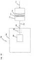
- FIG. 1is a perspective view of a first embodiment of a filter pack 50.
- the preferred filter pack 50 depictedincludes filter media 55 and a sealing system 60.
- the filter media 55is designed to remove particulates from a fluid, such as air, passing through the filter media 55, while the sealing system 60 is designed to seal the filter pack 50 against a sidewall of a housing or duct, as shown in FIGS. 8 and 9.
- sealingit is meant that the sealing system 60, under normal conditions, prevents unintended levels of fluid from passing through a region between the filter pack 50 and the sidewall of the housing or duct; i.e., the sealing system 60 inhibits fluid flow from avoiding passage through the filtering media 55 of filter pack 50.
- the filter media 55will be configured for straight-through flow.
- straight-through flowit is meant that the filter media 55 is configured in a construction 100 with a first flow face 105 (corresponding to an inlet end, in the illustrated embodiment) and an opposite, second flow face 110 (corresponding to an outlet end, in the illustrated embodiment), with fluid flow entering in one direction 114 through the first flow face 105 and exiting in the same direction 116 from the second flow face 110.
- the fluidwill enter through the inlet of the housing in one direction, enter the filter construction 100 through the first flow face 105 in the same direction, exit the filter construction 100 in the same direction from the second flow face 110, and exit the housing through the housing outlet also in the same direction.
- first flow face 105is described above as corresponding to an inlet end
- second flow face 110is described above as corresponding to an outlet end
- the inlet and outlet endscan be reversed. That is, the first flow face 105 depicted in FIG. 1 can correspond to an outlet end, while the second flow face 110 depicted in FIG. 1 can correspond to an inlet end.
- first flow face 105 and the second flow face 110are depicted as planar and as parallel. In other embodiments, the first flow face 105 and the second flow face 110 can be non-planar, for example, frusto-conical. Further, the first flow face 105 and second flow face 110 need not be parallel to each other.
- the filter construction 100will be a wound construction. That is, the construction 100 will typically include a layer of filter media that is turned completely or repeatedly about a center point. Typically, the wound construction will be a coil, in that a layer of filter media will be rolled a series of turns around a center point. In arrangements where a wound, coiled construction is used, the filter construction 100 will be a roll of filter media, typically permeable fluted filter media.
- FIG. 2is schematic, perspective view demonstrating the principles of operation of certain preferred media usable in the filter constructions herein.
- a fluted constructionis generally designated at 122.
- the fluted construction 122includes: a layer 123 of corrugations having a plurality of flutes 124 and a face sheet 132.
- the FIG. 2 embodimentshows two sections of the face sheet 132, at 132A (depicted on top of the corrugated layer 123) and at 132B (depicted below the corrugated layer 123).
- the preferred media construction 125 used in arrangements described hereinwill include the corrugated layer 123 secured to the bottom face sheet 132B.
- this media construction 125When using this media construction 125 in a rolled construction, it typically will be wound around itself, such that the bottom face sheet 132B will cover the top of the corrugated layer 123.
- the face sheet 132 covering the top of the corrugated layeris depicted as 132A. It should be understood that the face sheet 132A and 132B are the same sheet 132.
- the flute chambers 124When using this type of media construction 125, the flute chambers 124 preferably form alternating peaks 126 and troughs 128.
- the troughs 128 and peaks 126divide the flutes into an upper row and lower row.
- the upper flutesform flute chambers 136 closed at the downstream end, while flute chambers 134 having their upstream end closed form the lower row of flutes.
- the fluted chambers 134are closed by a first end bead 138 that fills a portion of the upstream end of the flute between the fluting sheet 130 and the second facing sheet 132B.
- a second end bead 140closes the downstream end of alternating flutes 136.
- both the first end bead 138 and second end bead 140are straight along all portions of the media construction 125, never deviating from a straight path.
- the first end bead 138is both straight and never deviates from a position at or near one of the ends of the media construction 125
- the second end bead 140is both straight and never deviates from a position at or near one of the ends of the media construction 125.
- the flutes 124 and end beads 138, 140provide the media construction 125 that can be formed into filter construction 100 and be structurally self-supporting without a housing.
- unfiltered fluidsuch as air
- the flute chambers 136have their upstream ends 146 open.
- the unfiltered fluid flowis not permitted to pass through the downstream ends 148 of the flute chambers 136 because their downstream ends 148 are closed by the second end bead 140. Therefore, the fluid is forced to proceed through the fluting sheet 130 or face sheets 132.
- the unfiltered fluidpasses through the fluting sheet 130 or face sheets 132, the fluid is cleaned or filtered.
- the cleaned fluidis indicated by the unshaded arrow 150.
- the fluidthen passes through the flute chambers 134 (which have their upstream ends 151 closed) to flow through the open downstream end 152 (Fig. 1) out the fluted construction 122.
- the unfiltered fluidcan flow through the fluted sheet 130, the upper facing sheet 132A, or lower facing sheet 132B, and into a flute chamber 134.
- the media construction 125will be prepared and then wound to form a rolled construction 100 of filter media.
- the media construction 125 preparedincludes the sheet of corrugations 123 secured with the end bead 138 to the bottom face sheet 132B (as shown in FIG. 2, but without the top face sheet 132A).
- the media construction 125will include a leading edge at one end and a trailing edge at the opposite end, with a top lateral edge and a bottom lateral edge extending between the leading and trailing edges.
- leading edgeit is meant the edge that will be initially turned or rolled, such that it is at or adjacent to the center or core of the rolled construction.
- the “trailing edge”will be the edge on the outside of the rolled construction, upon completion of the turning or coiling process.
- the leading edge and the trailing edgeshould be sealed between the corrugated sheet 123 and the bottom face sheet 132B, before winding the sheet into a coil, in these types of media constructions 125.
- the seal at the leading edgeis formed as follows: (a) the corrugated sheet 123 and the bottom face sheet 132B are cut or sliced along a line or path extending from the top lateral edge to the bottom lateral edge (or, from the bottom lateral edge to the top lateral edge) along a flute 124 forming a peak 126 at the highest point (or apex) of the peak 126; and (b) sealant is applied between the bottom face sheet 132B and the sheet of corrugations 123 along the line or path of cut.
- the seal at the trailing edgecan be formed analogously to the process of forming the seal at the leading edge. While a number of different types of sealant may be used for forming these seals, one usable material is a non-foamed sealant available from H.B. Fuller, St. Paul, Minnesota, identified under the designation HL0842.
- the media construction 125When using the media construction 125, it may be desired by the system designer to wind the construction 125 into a rolled construction of filter media, such as the filter construction 100 of FIG. 1.
- a variety of wayscan be used to coil or roll the media. Attention is directed to FIG. 3.
- the media construction 125is wound about a center mandrel 154 or other element to provide a mounting member for winding.
- the center mandrel 154may be removed or left to plug to act as a core at the center of the cylindrical filter construction 100 (FIG. 1).
- non-round center winding membersmay be utilized for making other filtering media shapes, such as filter media having an oblong, oval, rectangular, or racetrack-shaped profile.
- the media construction 125can also be wound without a mandrel or center core.
- One method of forming a coreless rolled constructionis as follows: (a) the troughs 128 of the first few corrugations of the corrugated sheet 123 spaced from the leading edge are scored from the top lateral edge to the bottom lateral edge (or from the bottom lateral edge to the top lateral edge) to help in rolling the construction 125; for example, the first four corrugations from the leading edge will have a score line cut along the troughs 128; (b) the bead 140 of sealant is applied along the top of the sheet of corrugation 123 along the lateral edge opposite from the lateral edge having end bead 138; (c) the leading edge is initially turned or rolled over against itself and then pinched together to be sealed with the sealant bead 140; and (d) the remaining corrugated sheet 123 having the bottom face sheet 132B secured thereto is coiled or rolled or turned around the pinched leading edge.
- coreless constructionscan be made from the media construction 125 by automated processes, as described in U.S. Patent Nos. 5,543,007 and 5,435,870, each incorporated by reference herein.
- the media constructioncan be rolled by hand.
- the system designerWhen using rolled constructions such as the filter construction 100, the system designer will want to ensure that the outside periphery of the construction 100 is closed or locked in place to prevent the filter construction 100 from unwinding.
- the outside peripheryis wrapped with a periphery layer.
- the periphery layercan be a non-porous, adhesive material, such as plastic with an adhesive on one side.
- the periphery layerprevents the filter construction 100 from unwinding and prevents the fluid from passing through the outside periphery of the filter construction 100, maintaining straight-through flow through the filter construction 100.
- the filter construction 100is secured in its rolled construction by sealing the trailing edge of the media construction 125 with an adhesive or sealant along a line 160 (Fig. 1) to secure the trailing edge to the outside surface of the filter construction 100.
- a bead of hot-meltmay be applied along the line 160.
- FIG. 1the second flow face 110 is shown schematically. There is a portion at 112 in which the flutes including the open ends 152 and closed ends 148 are depicted. It should be understood that this section 112 is representative of the entire flow face 110. For the sake of clarity and simplicity, the flutes are not depicted in the other remaining portions of the flow face 110.
- Top and bottom plan views, as well as side elevational views of a filter pack 50 usable in the systems and arrangements described hereinare depicted in copending and commonly assigned U.S. Patent Application Serial No. 29/101,193, filed February 26, 1999, and entitled, "Filter Element Having Sealing System," herein incorporated by reference.
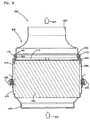
- FIG. 9the filter construction 100 is shown installed in a housing 305 (which can be part of an air intake duct into an engine or turbo).
- a housing 305which can be part of an air intake duct into an engine or turbo.
- airflows into the housing 305 at 306, through the filter construction 100, and out of the housing 305 at 307.
- a sealing system 60will be needed to ensure that air flows through the media construction 100, rather than bypass it.
- the particular sealing system 60 depictedincludes a frame construction 170 and a seal member 250.
- the frame construction 170provides a support structure or backing against which the seal member 250 can be compressed against to form a radial seal 172 with the duct or housing 305.
- the frame construction 170includes a rigid projection 174 that projects or extends from at least a portion of one of the first and second flow faces 105,110 of the filter construction 100.
- the rigid projection 174in the particular arrangement shown in FIG. 5, extends axially from the second flow face 110 of the filter construction 100.
- the particular FIG. 5 embodimentshows the projection 174 axially projecting above the entire second flow face 110, due to the planar shape of the second flow face 110.
- the projection 174can be designed to project above only a portion of the flow face. For example, in a frusto-conical filter construction, there could be a center portion at or near the core that extends above the projection 174.
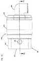
- FIG. 6depicts a cross-sectional view the particular frame construction 170 depicted in FIG. 5.
- the projection 174 shownhas a pair of opposite sides 176, 178 joined by an end tip 180.
- one of the first and second sides 176, 178will provide a support or backing to the seal member 250 such that a seal 172 can be formed between and against the selected side 176 or 178 and the appropriate surface of the housing or duct.
- the projection 174will be a continuous member forming a closed loop structure 182 (FIG. 4).
- the seal member 250can engage or be adjacent to either an interior side 184 of the loop structure 182, or the exterior side 186 of the loop structure 182.
- the seal member 250When engaging the interior side 184 of the loop structure 182, the seal member 250 can be compressed between the projection 174 and a tubular member inserted within the loop, such that the projection 174 and seal member 250 circumscribes the tubular member. This would form a radial seal between and against the outer portion of the tubular member and the interior side 176 of the projection 174 (and the loop structure 182).
- the seal member 250can also engage the exterior portion 186 of the loop structure 182.
- a housing or ductmay circumscribe the projection 174 and loop structure 182 including the seal member 250 to form a seal between and against the outer side 178 of the projection 174 and an inner surface of the housing or duct.
- the seal member 250engages or covers both of the interior side 184 and exterior side 186 of the loop structure 182. In the particular embodiment shown in FIG. 5, the seal member 250 engages the end tip 180 of the projection 174 as well, such that the seal member 250 covers the projection 174 from the exterior side 186, over the end tip 180, and to the interior side 184.
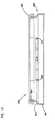
- FIG. 4is a schematic, plan view of the sealing system 60 of FIG. 1;
- FIG. 5is a fragmented, schematic, cross-sectional view of the filter pack 50 of FIG. 1 installed in housing 305; and
- FIG. 6is a schematic, cross-sectional view of the frame construction 170 of the sealing system 60 of FIG. 4.
- the frame construction 170will include a frame 205.
- the frame 205may be a variety of shapes. In the particular embodiment illustrated in FIG. 4, the shape of the frame 205 is generally circular.
- the frame 205 depicted in FIG. 4is convenient in that it is arranged and configured for attachment to the second flow face 110 of the filter construction 100.
- the frame 205has a band, skirt, or depending lip 251 that is generally circular and has an inside diameter.
- the inside diameteris approximately equal to the outside diameter of the filter construction 100.
- the depending lip 251depends or extends down a first distance from a bottom 252 surface of cross braces 210.
- the depending lip 251is arranged and configured to extend radially around the second flow face 110 the filter construction 100.
- the depending lip 251extends radially around the second flow face 110 of the filter media 100, such that the depending lip 251 extends inboard the first distance of the second flow face 110 of the filter construction 100, defining an overlap region 255.
- the frame 205is preferably secured to the filter construction 100.
- a variety of ways to secure the frame 205 to the filter construction 100are possible.
- One particularly preferred way to secure the frame 205 to the filter construction 100is by use of an adhesive.
- the adhesiveis oriented in the overlap region 255 between the depending lip 251 and the filter construction 100.
- the adhesivepermanently affixes the frame 205 to the filter construction 100 while preventing the fluid from leaking out through the overlap region 255 between the filter construction 100 and the frame 205.
- the frame 205may be temporarily attached to the filter construction 100. By the term “temporarily,” it is meant that the frame 205 may be removed from the filter construction 100 without damaging either the sealing system 60 or the filter construction 100.
- Cross braces 210support the frame 205.
- supportit is meant that the cross braces 210 prevent the frame 205 from radially collapsing under the forces exerted around the circumference of the frame 205.
- the particular projection 174 depictedpreferably includes a tip portion 263, or annular sealing support.
- the tip portion 263is generally circular and is arranged and configured for insertion into a housing or duct. When circular, the tip portion 263 defines an inside diameter.
- the frame 205includes a step 253. The step 253 provides a transition area between the larger inside diameter of the depending lip 251 and the smaller inside diameter of the tip portion 263.
- the tip portion 263provides support for the compressible seal member 250.
- the compressible seal member 250is preferably constructed and arranged to be sufficiently compressible to be compressed between the tip portion 263 of the frame 205 and a sidewall 260 of a housing or duct. When sufficiently compressed between the tip portion 263 and the sidewall 260, radial seal 172 is formed between the filter pack 50 and the sidewall 260.
- a variety of waysare possible to secure the seal member 250 to the tip portion 263.
- One particularly convenient and preferred wayis by molding the seal member 250 to engage, cover, or overlap both the outer radial side 270 of the tip portion 263 and the inner radial side 271 of the tip portion 263, including the end tip 180 (FIG. 7).
- One particular embodiment of this configurationis depicted in FIG. 7.
- the seal member 250, in FIG. 7,completely covers the tip portion 263.
- the tip portion 263 of the frame 205defines a wall or support structure between and against which a radial seal 172 may be formed by the compressible seal member 250.
- the compression of the compressible seal member 250 at the sealing system 60is preferably sufficient to form a radial seal under insertion pressures of no greater than 36 kg (80 lbs)., typically, no greater than 22,7 kg (50 lbs)., for example, about 9-18 kg (20-40 lbs)., and light enough to permit convenient and easy change out by hand.
- the amount of compression of the compressible seal member 250is at least fifteen percent, preferably no greater than forty percent, and typically between twenty and thirty-three percent.
- amount of compressionit is meant the physical displacement of an outermost portion of the seal member 250 radially toward the tip portion 263 as a percentage of the outermost portion of the seal member 250 in a resting, undisturbed state and not installed within a duct or subject to other forces.
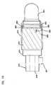
- FIG. 7is an enlarged schematic, fragmented view of a particular preferred seal member 250 in an uncompressed state.
- the seal member 250is a stepped cross-sectional configuration of decreasing outermost dimensions (diameter, when circular) from a first end 264 to a second end 265, to achieve desirable sealing.
- Preferred specifications for the profile of the particular arrangement shown in FIG. 7are as follows: a polyurethane foam material having a plurality of (preferably at least three) progressively larger steps configured to interface with the sidewall 260 (FIG. 5) and provide a fluid-tight seal.
- the compressible seal member 250defines a gradient of increasing internal diameters of surfaces for interfacing with the sidewall 260. Specifically, in the example shown in FIG. 7, the compressible seal member 250 defines three steps 266, 267, 268. The cross-sectional dimension or width of the steps 266, 267, 268 increases the further the step 266, 267, 268 is from the second end 265 of the compressible seal member 250. The smaller diameter at the second end 265 allows for easy insertion into a duct or housing. The larger diameter at the first end 264 ensures a tight seal.
- the compressible seal member 250needs to be compressed when the element is mounted in the housing 305 or duct. In many preferred constructions, it is compressed between about fifteen percent and forty percent (often about twenty to thirty-three percent) of its thickness, in the thickest portion, to provide for a strong robust seal yet still be one that can result from hand installation of the element with forces on the order of 36 kg (80 pounds) or less, preferably 22,7 kg (50 pounds) or less, and generally 9 - 18 kg (20-40 pounds).
- the filter pack 50can be arranged and configured to be press-fit against the sidewall 260 of the housing 305 or duct.
- the compressible seal member 250is compressed between the sidewall 260 and the tip portion 263 of the frame 205. After compression, the compressible seal member 250 exerts a force against the sidewall 260 as the compressible seal member 250 tries to expand outwardly to its natural state, forming radial seal 172 between and against the tip portion 263 and the sidewall 260.
- FIG. 8is a schematic, perspective view of an air cleaner 300.
- the filter pack 50is designed to be inserted into a housing 305 of an air cleaner 300.
- the housing 305is typically part of ductwork in airflow communication with an air intake system for an engine.
- ductworkor "duct” will include structures such as pipes, tubes, and air cleaner housings.
- the housing 305includes a body member or a first housing compartment 310 and a removable cover or second housing compartment 315.
- the first housing compartment 310is affixed to an object, such as a truck.
- the second housing compartment 315is removably secured to the first housing compartment 310 by a latching device 320.
- the latching device 320includes a plurality of latches 325.
- the first and second housing compartments 310, 315are circular.
- the first housing compartment 310has an outlet region 330.
- the outlet region 330is designed to allow the fluid to flow out of the filter assembly 300 during use.
- the second housing compartment 315has an inlet region 335.
- the inlet region 335is designed to allow the fluid to flow into the filter assembly 300 during use.
- the housing 305will be an in-line housing.
- the outlet region 330 and inlet region 335are coaxially aligned, to permit air to flow through the inlet region 335 and flow through the outlet region 330 in the same direction. This can be seen in FIG. 9.
- the filter pack 50is preferably constructed and arranged to be press-fit against the sidewall 260 of the housing 305.
- the second end 110 of the filter pack 50 with the attached frame 205 and compressible seal member 250is inserted into the first housing compartment 310.
- the filter pack 50is press-fit into the first housing compartment 310 such that the compressible seal member 250 is compressed between and against the tip portion 263 of the frame 205 and the sidewall 260 of the first housing compartment 310, to form radial seal 172 therebetween.
- the fluidenters the housing assembly 300 at the inlet region 335 of the second housing compartment 315, in the direction shown at 306.
- the fluidpasses through the filter construction 100.
- contaminantsare removed from the fluid.
- the fluidexits the housing assembly 300 at the outlet region 330, in the direction of 307.
- the compressible seal member 250 of the sealing system 60forms radial seal 172 to prevent contaminated fluid from exiting the housing assembly 300, without first passing through the filter construction 100.
- the filter pack 50can have additional separators for ensuring that the appropriate degree of filtering is conducted.
- the separatorscan be either upstream of the filter pack 50 or downstream of the filter pack 50, depending upon the particular application and the desired results.
- These separatorscan take the form of pre-cleaners in some embodiments, or post-cleaners (such as safety filters or secondary filters).
- these separatorsmay be in the form of single or multiple layers of filtering media, located either upstream or downstream of the filter construction 100.
- the filter media used in these applicationswill typically be selected based upon the degree of filtering desired and the amount of restriction introduced by the filter media.
- a layer of mediasuch as a sieve or screen can be used upstream of the filter construction 100. It may also be desired to introduce an additional amount of filtering just downstream of the filter construction 100. This can be accomplished by a layer (or multiple layers) of media immediately downstream of the filter construction 100.
- FIG. 17illustrates an alternative embodiment of the filter pack 50, shown generally at 50'.
- the filter pack 50'is configured and constructed analogously as the filter pack 50, illustrated in FIG. 1, with the exception of the first flow face 105', that corresponds to an upstream or an inlet end 106'.
- FIG. 17illustrates an end elevational view of the filter pack 50', viewing the upstream end 106'.
- the entire upstream end 106'is covered by a layer of media 107' for separating large particles from the gas stream before the gas stream reaches the filter construction 100.
- the media 107'can be of a variety of types.
- the media 107'will be sized to allow for the removal of particles such as butterflies, leaves, large clumps of dirt, and other types of debris.
- One type of media usablehas the following characteristics and properties: polyester material; 50% of the fibers being about 15 denier and 50% of the fibers being about 6 denier by weight; the binder holding the fibers together being oil resistant rubber modified PVC; a basis weight of (6.6 oz/yd 2 ) 224 g/m 2 ; a thickness of about 9,4 mm (0.37 inches); a permeability of about 1068 m/min (3500 ft/m) in a 6,25 mm (0.5 in.) H 2 O restriction.
- FIG. 18is an end elevational view of an alternative embodiment of the filter pack 55, as viewed from the second flow face 110".
- the filter pack 50" shown in FIG. 18is constructed analogously as the filter pack 50 of FIG. 1, with the exception of an additional separator 111" located downstream of the filter construction 100.
- the separator 111"is in the form of a layer of media 112" located downstream of the filter construction 100.
- the layer of media 112"can be either immediately adjacent and against the filter construction 100, or it may be located downstream of the frame 205".
- the media 112"is immediately downstream of and against the filter construction 100. That is, the media 112" is located between the filter construction 100 and the cross braces 210" of the frame 205".
- the type of media 112" utilizedwill depend upon the desired degree of filtering and the amount of restriction that is introduced.
- the media 112"can be a single layer or multiple layers. In the one illustrated in FIG 18, the media 112" includes nonwoven, nonpleated, fibrous depth media 113".
- One usable material for depth media 113"has the following characteristics: 1 layer of (4.0-4.8 oz/yd 2 ) 136-163 g/m 2 polyester fiber depth media (mixed fibers); (0.55-0.70") 14-18 mm thickness freestate (as measured under 1,4 mbar (0.002 psi) compression); average fiber diameter about 21.0 micron (mass weighted average) or about 16.3 micron (length weighted average); permeability (minimum) (500 ft/min) 152 m/min.; free state solidity about 0.6-1.0%, typically about 0.7%.
- a filter pack 50that includes both an upstream filter 107' and a downstream filter 111".
- FIG. 10is a perspective view of another embodiment of a filter pack 450.
- the filter pack 450includes filter media 455 and a sealing system 460.
- the filter media 455is designed to remove contaminants from a fluid, such as air, passing through the filter media 455.
- the sealing system 460is designed to seal the filter media 455 to a housing or duct.
- the filter media 455will be configured in a filter construction 470 with a first flow face 471 and an opposite, second flow face 472. Attention is directed to FIG. 11.
- the filter construction 470is configured for straight-through flow. This means, as explained above, that fluid to be filtered will enter the first flow face 471 in a certain direction 477 (FIG. 10) and exit the second flow face 472 in the same direction 478 (FIG. 10).
- the filter construction 470can have a variety of configurations and cross-sectional shapes. In the particular embodiment illustrated in FIG. 11, the filter construction 470 has a non-circular cross-section. In particular, the FIG. 11 embodiment of the filter construction 470 has an ob-round or "racetrack" cross-sectional shape. By “racetrack” cross-sectional shape, it is meant that the filter construction 470 includes first and second semicircular ends 511, 512 joined by a pair of straight segments 513, 514.
- the filter construction 470will be a wound construction. That is, the construction 470 will include a layer of filter media that is turned completely or repeatedly about a centerpoint. In certain preferred arrangements, the wound construction will be a coil, in that a layer of filter media will be rolled a series of turns about a centerpoint. In further preferred arrangements, the filter construction 470 will be a rolled construction, typically a roll of filter media, for example permeable fluted filter media.
- a single-faced filter mediasuch as the filter media 122 illustrated in FIG. 2, is wound about a center mandrel or other structure to provide a mounting member for winding.
- the center mandrelmay be removed or left to plug the center of the filter construction 470.
- a center core 454is illustrated as occupying the center of the coil of filter media 455.
- FIGS. 10 and 11certain portions 475 are depicted showing the flutes, including the open and closed ends. It should be understood that this portion or section 475 is representative of the entire flow face 472 (as well as the first flow face 471). For the sake of clarity and simplicity, the flutes are not depicted in the other remaining portions of the flow face 472.
- Top and bottom plan views, as well as side elevational views of the filter pack 450 usable in the systems and arrangements described hereinare depicted in copending and commonly assigned U.S. Patent Application Serial No. 29/101,193, filed February 26, 1999, and entitled, "Filter Element Having Sealing System," herein and incorporated by reference.
- the filter pack 450includes a sealing system 460.
- the sealing system 460includes a frame 605 and a seal member 650.
- FIG. 12While a variety of configurations are contemplated herein, one particularly preferred embodiment of the frame 605 is shown in perspective view in FIG. 12.
- the frame 605has a non-circular, for example, obround and in particular, a racetrack shape and is arranged and configured for attachment to the second end 510 of the filter media 455.
- the frame 605has a band or skirt or depending lip 651 that is generally racetrack shaped.
- the depending lip 651depends or extends down a distance from a bottom surface 652 of cross braces 610.
- the depending lip 651is arranged and configured to extend radially around the second end 570 of filter construction 470.
- the depending lip 651 of the frame 605extends radially around the second end 510 of the filter construction 470, such that the depending lip 651 extends inboard the distance from bottom surface 652 of cross braces 610 of the second end 510 of the filter construction 470, defining an overlap region 555 (FIG. 15).
- the frame 605can be secured to the filter construction 470 in a number of ways.
- One particularly convenient wayis by securing the frame 605 to the filter construction 470 by adhesive.
- the adhesiveis placed in the overlap region 555 between the frame 605 and the filter construction 470 as previously described herein.
- inward forcesare exerted around the circumference of the frame 605.
- Inward forces exerted against the semicircular ends 511, 512can cause the straight segments 513, 514 to bow or bend.
- Structureis provided as part of the frame 605 to prevent the straight segments 513, 514 from bowing.
- cross braces 610are provided to provide structural rigidity and support to the straight segments 513, 514.
- the particular cross braces 610 depictedform a truss system 612 between the opposing straight segments 513,514.
- the truss system 612includes a plurality of rigid struts 614, preferably molded as a single piece with the remaining portions of the frame 605.
- the frame 605is constructed analogously to the frame 205.
- the frame 605includes a tip portion 663.
- the tip portion 663acts as an annular sealing support.
- the tip portion 663has the same cross-sectional configuration as the filter construction 470.
- the tip portionis noncircular, specifically, racetrack shaped.
- the frame 605includes a step 653. The step 653 provides a transition area between the cross-sectional width of the depending lip 651 and the smaller cross-sectional width of the tip portion 663.
- the compressible seal member 650has structure analogous to the that of the compressible seal member 250 of FIG. 7.
- the filter pack 450will be installed in a duct or an air cleaner housing.
- the air cleaner housingwill be an in-line housing.
- FIG. 14illustrates an air cleaner 670 having one type of in-line housing 672.
- the housing depictedis a two-piece housing including a cover 674 and a body member 676.
- the cover 674defines an airflow inlet 678.
- the body member 676defines an airflow outlet 680.
- the housingfurther includes a pre-cleaner arrangement 679 upstream of the filter pack 450, such as that described in U.S. Pat. Nos. 2,887,177 and 4,162,906, incorporated by reference herein.
- the pre-cleaner arrangement 679is in the cover 674.
- the cover 674includes a dust ejector 681 that expels dust and debris collected in the pre-cleaner 679.
- FIG. 15is a schematic cross-sectional view of the air cleaner 670 of FIG. 14 and showing the filter pack 450 installed therewithin.
- the compressible seal member 650is compressed between the sidewall 660 and the tip portion 663 of the frame 605. As the filter pack 450 is press-fit, the compressible seal member 650 is compressed between and against the frame 605 (specifically, in the particular embodiment shown, the tip portion 663) and the sidewall 660. After compression, the compressible seal member 650 exerts a force against the sidewall 660 as the compressible seal member 650 tries to expand outwardly to its natural state, forming a radial seal 685 with the sidewall 660.
- FIG. 16One particular type of system is depicted schematically in FIG. 16 generally at 700.
- equipment 702such as a vehicle, having an engine 703 with some defined rated air flow demand, for example at least 500 cfm, and typically 700-1200 cfm is shown schematically.
- the equipment 702may comprise a bus, an over-the-highway truck, an off-road vehicle, a tractor, or marine application such as a powerboat.
- the engine 703powers the equipment 702, through use of an air and fuel mixture.
- air flowis shown drawn into the engine 703 at an intake region 705.
- An optional turbo 706is shown in phantom, as optionally boosting the air intake into the engine 703.
- An air cleaner 710 having a filter construction 712 and a secondary element 713is upstream of the engine 703 and the turbo 706.
- airis drawn in at arrow 714 into the air cleaner 710 and through a primary element 712 and secondary element 713. There, particles and contaminants are removed from the air.
- the cleaned airflows downstream at arrow 716 into the intake 705. From there, the air flows into the engine 703 to power the equipment 702.
- the filter packs described hereinare removable and replaceable from whatever system in which they are installed.
- the filter pack 50, or filter pack 650will be installed in an air cleaner housing such as those shown in FIGS. 9 and 15, respectively. After a certain number of hours of use, the media in the filter constructions will become occluded, and the restriction in the filter packs will increase.
- the filter packswill be periodically replaced to maintain the appropriate removal of particulates from a fluid, without introducing too high of a restriction.
- the filter constructions hereinwill include a visual indicator of useful life.
- Some systemsmay include a restriction indicator to provide information to the user regarding the appropriate time to change out the filter pack.
- the userwill need access the filter pack.
- the filter packis installed in an air cleaner housing such as those shown in FIG. 9 or FIG. 15, the user will unlatch the cover from the body member, and remove the cover from the body member. This will expose an opening. The user will grasp the filter pack and break the radial seal formed by the filter pack against the sidewall of the housing or duct.
- the seal member and the housing or ductwill be designed such that the user will need to exert a force of no more than about 36 kg (80 lbs.), preferably no more than 22,7 kg (50 lbs.), and in some applications between ) and 18 kg (15 and 40 lbs.) to break the radial seal and remove the filter pack.
- the filter packwill be constructed of non-metallic materials, such that it is readily incineratable.
- the filter packwill comprise at least 95 percent, and typically at least 98 percent nonmetallic materials.
- the usergrasps the filter pack and inserts it through an opening in the duct or housing.
- the filter packis inserted into the opening until the seal member is sufficiently compressed against the inner annular wall of the housing to form a radial seal between and against the housing wall and the tip portion of the frame.
- the covermay then be oriented over the exposed end of the filter pack to close the opening. The cover may then be latched to the body member.
- the axial length of the filter media 100 of FIG. 2will be between (3 inches) about 8 cm and (10 inches) about 25 cm, and in one example would be approximately (6 inches) about 15 cm.
- the outside diameter of the filter media 100will be between (3 inches) about 38 cm and (15 inches) about 38 cm, and in one example would be approximately (10 inches) about 25 cm.
- the distance (FIG. 5) that the depending lip 251 of the frame 205 (FIG. 5) extends inboard of the second end 110 (FIG. 5) of the filter construction 100will be between (0.2 inches) about 5 mm and (1 inch) about 2.5 cm, and in one example would be (0.6 inches) about 1.5 cm.
- the diameter of the depending lip 251will be between (3 inches) about 7 cm and (15 inches) about 38 cm, and in one example would be approximately (10 inches) about 25 cm.
- the diameter of the tip portion 263will be between (2.5 inches) about 6 cm and (14 inches) 36 cm, and in one example would be approximately 9.5 inches (about 24 cm).
- the filter elementwill provide at least about 0,5 m 2 (5 sq. ft) and typically about 1,9-12 m 2 (20-130 sq. ft)., for example about 4 m 2 (45 sq. ft). of media surface area. It will occupy a volume of no greater than about 28 dm 3 (1 ft 3 ), and typically between about 0,9-14 dm 3 (0.03-0.5 ft 3) , and for example about 5,7-11 dm 3 (0.2-0.4 ft 3 ).
- the diameter of the outlet region 330 (FIG. 9) of the first housing compartment 310 (FIG. 9)will be between (3 inches) about 8 cm and (10 inches) about 25 cm, and in one example would be (7 inches) about 18 cm.
- the diameter (FIG. 9) of the inlet region 335 (FIG. 9) of the second housing compartment 315 (FIG. 9)will be between (3 inches) about 8 cm and (10 inches) about 25 cm, and in one example would be (5.8 inches) about 15 cm.
- the axial length of the filter construction 470will be between 3 inches about 8 cm and (10 inches) about 25 cm, and in one example would be approximately (6 inches) about 15 cm.
- the semicircular ends 511, 512will have a radius of between (1 inch) about 2.5 cm and (5 inches) about 13 cm, and in one example have a radius of (2.7 inches) about 7 cm.
- the straight segments 513, 514will have a length greater than (0.1 inches) about 2.5 mm, and in one example, would be (4.9 inches) about 12 cm.
- the distance that the frame 605 extends inboard of the filter construction 470will be between (0.2 inches) about 5mm and (1 inch) about 2.5 cm, and in one example would be (0.6 inches) about 1.5 cm.
- the filter elementwill provide at least about 0,47 m 2 (5 sq. ft) and typically about 1,9-12 m 2 (20-130 sq). ft., for example about 4,2 m 2 (45 sq. ft.) of media surface area. It will occupy a volume of no greater than about 28,3 dm 3 (1 ft 3) , and typically between 0,9-14 dm 3 (0.03-0.5 ft 3 ), and for example about 5,7-11 dm 3 (0.2-0.4 ft 3) .
- the media 122can comprise cellulose.
- cellulose mediawith the following properties: a basis weight of about (45-55 lbs./3000 ft 2 ) 84.7 g/m 2 , for example, (48-54 lbs./3000 ft 2 ); a thickness of about (0.005-0.015 in) 0,13-0,38 mm, for example about (0.010 in.) 0.25 mm; frazier permeability of about 6-7,6 m/min (20-25 ft/min), for example, about (22 ft/min) 6.7 m/min; pore size of about 55-65 microns, for example, about 62 microns; wet tensile strength of at least about 8 kg/cm (7 lbs/in), for example, (8.5 lbs./in) 9,7 kg/cm; burst strength wet off of the machine of about 1-1,7 bar (15-25 psi), for example, about (23 psi) 1,
- the cellulose mediacan be treated with fine fiber, for example, fibers having a size (diameter) of 5 microns or less, and in some instances, submicron.
- fine fiberfor example, fibers having a size (diameter) of 5 microns or less, and in some instances, submicron.
- a variety of methodscan be utilized for application of the fine fiber to the media. Some such approaches are characterized, for example, in U.S. Patent 5,423,892, column 32, at lines 48-60. More specifically, such methods are described in U.S. Patent Nos. 3,878,014; 3,676,242; 3,841,953; and 3,849,241, incorporated herein by reference.
- An alternativeis a trade secret approach comprising a fine polymeric fiber web positioned over conventional media, practiced under trade secret by Donaldson Company under the designation ULTRA-WEB®.
- the frame 205(FIG. 5) will be constructed of a material that will provide structural integrity and is not subject to creep.
- the frame 205will be constructed of a non-metallic material such that it is environmentally friendly and either recyclable or readily incineratable.
- the frame 205can be constructed from most plastics, for example, glass reinforced plastic.
- One usable reinforced plasticis propylene or nylon. Of course, other suitable materials may be used.
- the compressible seal member 250can be made from a variety of materials. There is no particular preference, provided that the seal member 250 forms a seal in the proper location under compression.
- One usable materialwill be a soft polymeric material, such as foamed urethane.
- One example usable materialincludes foamed polyurethane, processed to an end product having an "as molded" density of fourteen to twenty-two pounds per cubic foot.
- Foamed polyurethanesare available from a variety of sources, such as BASF Corporation of Wyandotte, Michigan.
- One example of a foamed polyurethanecomprises a material made with I35453R resin and I305OU isocyanate, which is sold exclusively to the assignee Donaldson by BASF Corporation.
- the materialsshould be mixed in a mix ratio of 100 parts I35453 resin to 36.2 parts I305OU isocyanate (by weight).
- the specific gravity of the resinis 1.04 (8.7 pounds/gallon), and for the isocyanate it is 1.20 (10 pounds/gallon).
- the materialsare typically mixed with a high dynamic shear mixer.
- the component temperaturesshould be 21-35 °C (70-95 °F).
- the mold temperaturesshould be 46-57 °C (115-135° F).
- the resin material I35453Rhas the following description:
- the I3050U isocyanate descriptionis as follows:
Landscapes
- Chemical & Material Sciences (AREA)
- Chemical Kinetics & Catalysis (AREA)
- Filtering Of Dispersed Particles In Gases (AREA)
- Glass Compositions (AREA)
- Infusion, Injection, And Reservoir Apparatuses (AREA)
- Filtering Materials (AREA)
- Studio Devices (AREA)
- Piezo-Electric Or Mechanical Vibrators, Or Delay Or Filter Circuits (AREA)
Abstract
Description
Claims (12)
- A filter element arrangement (50, 450) for use in an air cleaner housing(305, 672) having an internal annular sealing surface (260, 660); the filterelement arrangement (50, 450) being removable and replaceable within theair cleaner housing (305, 672) upon relative axial movement between thefilter element arrangement (50, 450) and the internal annular sealingsurface (260, 660) of the housing (305, 672); the filter element arrangement(50, 450) comprising:(a) a coiled media construction (125, 470) comprising a sheet ofcorrugations (123) secured to a bottom face sheet (132) andconfigured in a coil;(i) the coiled media construction (125, 470) having: first andsecond ends; a first flow face (105, 471) at the first end; anda second flow face (110, 472) at the second end;(ii) the media within said coiled media construction (125, 470)forming a plurality of flutes (124); each of the flutes (124)having a first end (146) positioned adjacent to the first flowface (105, 471) and a second end (148) positioned adjacentto the second flow face (110, 472);(A) a first set (136) of selected ones of the flutes (124)being open at the first end (146) and closed at thesecond end (148); and(B) a second set (134) of selected ones of said flutes(124) being closed at the first end (146) and open atthe second end (148);(b) a sealing system (60, 460) including a seal member (250, 650) anda frame construction (170,605) arranged around one of the first andsecond ends of the coiled media construction;(i) the frame construction (170, 605) including an extension(174, 663) projecting axially from one of the first and secondflow faces;(A) the extension (174, 663) of the frame construction(170, 605) having an outer circumferential surface(178);(B) the extension (174, 663) of the frame construction(170, 605) being an annular sealing support for theseal member (250, 650);(ii) the seal member (250, 650) being positioned on.. and beingsupported by, the extension (174, 663) of the frameconstruction (170, 605);(A) at least a portion of the seal member (250, 650) beingpositioned on and peripherally around the outercircumferential surface (178) of the extension (174,663);(B) the seal member (250, 650) including an outwardlydirected, peripheral, sealing surface, the seal memberperipheral sealing surface being oriented to form areleasable, peripherally directed, seal (172; 685)between the filter element arrangement (50, 450) anda housing internal annular sealing surface (260, 660),as a result of axial insertion of the filter elementarrangement (50, 450) into sealing engagement withthe internal annular sealing surface of the air cleanerhousing (305, 672).
- A filter element arrangement (450) according to claim 1 wherein:the coiled media construction (470) has a cross-section including a pair ofcurved ends (511, 512) joined by a pair of straight segments (513, 514).
- A filter element arrangement (450) according to claim 2 wherein:the frame construction extension (663) includes a pair of curved ends joinedby a pair of straight segments.
- A filter element arrangement (50, 450) according to any one of claims 1-3wherein:the frame construction (170, 605) includes radially supporting cross braces (210, 610).
- A filter element arrangement (50, 450) according to any one of claims 1-4wherein:the outwardly directed, peripheral, surface of the seal member (250, 650)defines a cross-sectional configuration of steps (266, 267, 268) increasingfrom an end tip (180) of the extension (174, 663) toward a lip member (251,651).
- A filter element arrangement (50, 450) according to any one of claims 1-5wherein:the outer circumferential surface of the frame construction extension (174,663) is continuous and uninterrupted.
- A filter element arrangement (50, 450) according to any one of claims 1-6wherein:(a) said frame construction extension (174, 663) includes an end tip(180); an outer surface (186), and an opposite inner surface (184);and(b) said seal member (250, 650) includes: a first portion being orientedagainst said outer surface (186) of said extension (174, 663); asecond portion oriented against said end tip (180); and a thirdportion oriented against said inner surface (184).
- A filter element arrangement (50, 450) according to any one of claims 1-7operably installed in an air deaner housing (305, 672) of an engine (703)least 850 m3/h (500 cfm) through the filter element arrangement (50, 450).
- A filter element arrangement (50, 450) operably installed according to claim8 wherein:the seal member (250, 650) is compressed at least 15% between theextension (174, 663) of the frame construction and an annular sealingsurface (260, 660) of the air cleaner housing (305, 672).
- A filter element arrangement (50, 450) according to any one of claims 1-9wherein:said seal member (250, 650) comprises compressible polyurethane foam.
- A method of servicing an air cleaner (300, 670), having a housing (305, 672)with an inner annular sealing surface (260, 660); said method including astep of:axially inserting a filter element arrangement (50, 450) according to any oneof claims 1-7 into sealing engagement with the internal annular sealingsurface of the housing (305, 672).
- A method of constructing a filter element arrangement (50, 460) of the typecharacterized in any one of claims 1-7; the method comprising steps of:securing a sealing system (60,460) including a frame construction (170,605) and a seal member (250, 650) to an end of a coiled media construction(125, 470) according to claim 1(a).
Priority Applications (6)
| Application Number | Priority Date | Filing Date | Title |
|---|---|---|---|
| EP08153233.5AEP1946817B1 (en) | 1999-02-26 | 2000-02-23 | Air Cleaner |
| EP07100014.5AEP1795246B2 (en) | 1999-02-26 | 2000-02-23 | Air cleaner |
| EP03021269.0AEP1410832B2 (en) | 1999-02-26 | 2000-02-23 | Filter element with sealing system |
| EP10184639AEP2292312A1 (en) | 1999-02-26 | 2000-02-23 | Sealing system for filter |
| DE60006789TDE60006789T3 (en) | 1999-02-26 | 2000-02-23 | SEALING SYSTEM FOR FILTERS |
| DE20023795UDE20023795U1 (en) | 1999-02-26 | 2000-02-23 | Filter for removing particulates from gas flow streams of e.g. engines for motorized vehicles or power generation equipment, includes media and sealing system |
Applications Claiming Priority (5)
| Application Number | Priority Date | Filing Date | Title |
|---|---|---|---|
| US09/258,481US6190432B1 (en) | 1999-02-26 | 1999-02-26 | Filter arrangement; sealing system; and methods |
| US258481 | 1999-02-26 | ||
| US502346 | 2000-02-10 | ||
| US09/502,346US6350291B1 (en) | 1999-02-26 | 2000-02-10 | Filter arrangement; sealing system; and methods |
| PCT/US2000/004557WO2000050149A1 (en) | 1999-02-26 | 2000-02-23 | Sealing system for filter |
Related Child Applications (8)
| Application Number | Title | Priority Date | Filing Date |
|---|---|---|---|
| EP03021269.0ADivisionEP1410832B2 (en) | 1999-02-26 | 2000-02-23 | Filter element with sealing system |
| EP03021129.6ADivisionEP1374963A2 (en) | 1999-02-26 | 2000-02-23 | Sealing system for filter |
| EP08153233.5ADivisionEP1946817B1 (en) | 1999-02-26 | 2000-02-23 | Air Cleaner |
| EP03021269.0Division-Into | 2003-09-19 | ||
| EP03021129.6Division-Into | 2003-09-22 | ||
| EP07100014.5Division-Into | 2007-01-02 | ||
| EP08153233.5Division-Into | 2008-03-25 | ||
| EP10184639.2Division-Into | 2010-09-30 |
Publications (3)
| Publication Number | Publication Date |
|---|---|
| EP1159052A1 EP1159052A1 (en) | 2001-12-05 |
| EP1159052B1true EP1159052B1 (en) | 2003-11-26 |
| EP1159052B2 EP1159052B2 (en) | 2011-08-03 |
Family
ID=26946659
Family Applications (1)
| Application Number | Title | Priority Date | Filing Date |
|---|---|---|---|
| EP00910290AExpired - LifetimeEP1159052B2 (en) | 1999-02-26 | 2000-02-23 | Sealing system for filter |
Country Status (11)
| Country | Link |
|---|---|
| US (3) | US6610117B2 (en) |
| EP (1) | EP1159052B2 (en) |
| JP (1) | JP4463994B2 (en) |
| CN (2) | CN1201845C (en) |
| AT (3) | ATE254949T1 (en) |
| AU (1) | AU781353B2 (en) |
| BR (1) | BR0008458B1 (en) |
| CA (1) | CA2360445C (en) |
| DE (2) | DE60006789T3 (en) |
| ID (1) | ID30248A (en) |
| WO (1) | WO2000050149A1 (en) |
Cited By (15)
| Publication number | Priority date | Publication date | Assignee | Title |
|---|---|---|---|---|
| FR2884439A1 (en)* | 2005-04-19 | 2006-10-20 | Filtrauto Sa | Filter element for fitting into air filter housing has joint designed to fix frame to filter medium and seal filter medium to housing |
| US7303604B2 (en) | 1999-02-26 | 2007-12-04 | Donaldson Company, Inc. | Filter arrangement; sealing system; and methods |
| US7396375B2 (en) | 2002-05-09 | 2008-07-08 | Donaldson Company, Inc. | Air filter having fluted filter media |
| US7396376B2 (en) | 2003-12-22 | 2008-07-08 | Donaldson Company, Inc. | Seal arrangement for filter element; filter element assembly; and, methods |
| DE202007006962U1 (en) | 2007-05-11 | 2008-09-18 | Mann+Hummel Gmbh | Compact filter element |
| US7648545B2 (en) | 2005-06-24 | 2010-01-19 | Mann + Hummel Gmbh | Filter sealing system |
| US7655074B2 (en) | 2003-11-12 | 2010-02-02 | Donaldson Company, Inc. | Filter arrangements; side-entry housings; and methods |
| US7708797B2 (en) | 2006-01-20 | 2010-05-04 | Donaldson Company, Inc. | Air cleaner configured for receipt of various sized filter cartridges; components thereof; and, methods |
| US7713321B2 (en) | 2006-06-22 | 2010-05-11 | Donaldson Company, Inc. | Air cleaner arrangements; components thereof; and, methods |
| US7905936B2 (en) | 2004-04-30 | 2011-03-15 | Donaldson Company, Inc. | Filter arrangements; housing; assemblies; and, methods |
| US7972404B2 (en) | 2006-06-22 | 2011-07-05 | Donaldson Company, Inc. | Air cleaner arrangements; components thereof; and, methods |
| US8034144B2 (en) | 1999-02-26 | 2011-10-11 | Donaldson Company, Inc. | Filter arrangement; sealing system; and methods |
| US8382876B2 (en) | 2004-06-18 | 2013-02-26 | Donaldson Company, Inc. | Air cleaner arrangement; serviceable filter cartridge; and, methods |
| US8409316B2 (en) | 2005-11-09 | 2013-04-02 | Donaldson Company, Inc. | Seal arrangement for filter element; filter element assembly; and, methods |
| EP3377192B1 (en)* | 2015-11-20 | 2023-06-14 | Baldwin Filters, Inc. | Adhesive flute support while winding fluted pack |
Families Citing this family (128)
| Publication number | Priority date | Publication date | Assignee | Title |
|---|---|---|---|---|
| CN1079275C (en) | 1996-04-26 | 2002-02-20 | 唐纳森公司 | Fluted filter media |
| EP1795249B1 (en)* | 2000-09-05 | 2018-07-25 | Donaldson Company, Inc. | Air filtration arrangements having fluted media constructions |
| US6673136B2 (en)* | 2000-09-05 | 2004-01-06 | Donaldson Company, Inc. | Air filtration arrangements having fluted media constructions and methods |
| US6800117B2 (en) | 2000-09-05 | 2004-10-05 | Donaldson Company, Inc. | Filtration arrangement utilizing pleated construction and method |
| EP1795250A1 (en) | 2000-09-05 | 2007-06-13 | Donaldson Company, Inc. | Filter element utilizing pleated construction |
| US6610126B2 (en) | 2001-06-06 | 2003-08-26 | Donaldson Company, Inc. | Filter element having sealing members and methods |
| JP3595311B2 (en)* | 2002-03-28 | 2004-12-02 | 川崎重工業株式会社 | Engine air cleaner |
| US6966940B2 (en) | 2002-04-04 | 2005-11-22 | Donaldson Company, Inc. | Air filter cartridge |
| KR20050098922A (en) | 2003-02-11 | 2005-10-12 | 도널드선 컴파니 인코포레이티드 | Air cleaner arrangements; serviceable filter elements;and,method |
| WO2004082795A2 (en)* | 2003-03-18 | 2004-09-30 | Donaldson Company, Inc. | Improved process and materials for coiling z-filter media, and/or closing flutes of filter media; and, products |
| TWD102052S1 (en)* | 2003-03-25 | 2004-12-21 | 西部技研股份有限公司 | Sealing element for dehumidification unit |
| US6905536B2 (en)* | 2003-06-11 | 2005-06-14 | Arvin Technologies, Inc. | Increased surface area hydrocarbon adsorber |
| ATE466636T1 (en)* | 2003-07-18 | 2010-05-15 | Mann & Hummel Gmbh | FILTER ELEMENT, ESPECIALLY FOR CLEANING COMBUSTION AIR |
| US7282077B2 (en)* | 2003-10-24 | 2007-10-16 | Briggs & Stratton Corporation | Air cleaner assembly |
| WO2005058460A1 (en)* | 2003-12-17 | 2005-06-30 | Sunny Metal Inc. | A fluid filter |
| US20090266041A1 (en)* | 2003-12-22 | 2009-10-29 | Donaldson Company, Inc. | Seal arrangement for filter element; Filter element assembly; and, methods |
| WO2005079954A1 (en) | 2004-02-17 | 2005-09-01 | Donaldson Company, Inc. | Air cleaner arrangements; serviceable filter elements; and, methods |
| CN103736326B (en) | 2004-03-24 | 2016-01-06 | 唐纳森公司 | Filter cell, air cleaner assembly and method |
| USD506539S1 (en) | 2004-03-24 | 2005-06-21 | Donaldson Company, Inc. | Filter cartridge |
| WO2005095783A1 (en)* | 2004-03-31 | 2005-10-13 | Mann+Hummel Gmbh | Suction filter for an internal combustion engine of a motor vehicle |
| GB0409548D0 (en)* | 2004-04-29 | 2004-06-02 | King S College London | Robotic hand |
| CA2564883C (en) | 2004-04-30 | 2013-12-17 | Paul R. Coulonvaux | Filter arrangements; housings; assemblies; and, methods |
| BRPI0511915B1 (en) | 2004-06-08 | 2016-07-12 | Donaldson Co Inc | air filter cartridge |
| EP2243536B1 (en) | 2004-06-14 | 2013-11-20 | Donaldson Company, Inc. | Air filter arrangement and cartridge |
| ATE457810T1 (en) | 2004-07-20 | 2010-03-15 | Donaldson Co Inc | Z-FILTER MEDIA PACKING ASSEMBLY, FILTER CARTRIDGE, AIR PURIFICATION DEVICE ASSEMBLY AND METHOD |
| MX2007001427A (en)* | 2004-08-06 | 2007-04-02 | Donaldson Co Inc | Air filter arrangement; assembly; and, methods. |
| DE102005010443A1 (en)* | 2004-09-21 | 2006-03-23 | Mann + Hummel Gmbh | filter element |
| US7318851B2 (en) | 2004-11-02 | 2008-01-15 | Baldwin Filters, Inc. | Filter element |
| US8042694B2 (en)* | 2004-11-02 | 2011-10-25 | Baldwin Filters, Inc. | Gathered filter media for an air filter and method of making same |
| US20060090431A1 (en)* | 2004-11-02 | 2006-05-04 | Baldwin Filters, Inc. | Filter assembly with combination filter element |
| US20070186528A1 (en)* | 2006-02-15 | 2007-08-16 | Baldwin Filters, Inc. | Fluted filter apparatus |
| US20060091061A1 (en)* | 2004-11-02 | 2006-05-04 | Baldwin Filters, Inc. | Filter assembly with sealing system |
| US7931725B2 (en) | 2004-11-02 | 2011-04-26 | Baldwin Filters, Inc. | Fluted filter apparatus |
| US20110197556A1 (en) | 2004-11-02 | 2011-08-18 | Baldwin Filters, Inc. | Filter element |
| US20060091084A1 (en)* | 2004-11-02 | 2006-05-04 | Baldwin Filters, Inc. | Fluted filter media with intermediate flow restriction and method of making same |
| US7909954B2 (en)* | 2004-11-03 | 2011-03-22 | Baldwin Filters, Inc. | Method and apparatus for winding a filter media pack |
| US7255300B2 (en) | 2004-11-03 | 2007-08-14 | Baldwin Filters, Inc. | Method and apparatus for winding a filter media pack |
| US7294178B2 (en)* | 2004-11-08 | 2007-11-13 | Visteon Global Technologies, Inc. | Low loss hydrocarbon (HC) adsorber device for air induction system |
| US7569090B2 (en) | 2004-11-12 | 2009-08-04 | Donaldson Company, Inc. | Method of forming filter arrangements; and, apparatus |
| DE102004054970A1 (en) | 2004-11-13 | 2006-05-18 | Mann + Hummel Gmbh | Activated carbon coated filter element for preventing the escape of hydrocarbons from an opening |
| DE102004000044B4 (en)* | 2004-11-17 | 2013-08-29 | Mann + Hummel Gmbh | Air filtration system |
| DE102004059279B4 (en)* | 2004-12-09 | 2018-05-03 | Mann + Hummel Gmbh | air filter |
| CN101163535B (en)* | 2005-01-13 | 2012-10-03 | 唐纳森公司 | Air filter device |
| US7655062B2 (en)* | 2005-02-10 | 2010-02-02 | Euro-Pro Operating, Llc | Filter assembly for a vacuum cleaner |
| ATE399050T1 (en)* | 2005-04-15 | 2008-07-15 | Mann & Hummel Gmbh | FILTER SYSTEM |
| KR101697469B1 (en) | 2005-10-11 | 2017-01-17 | 도날드슨 컴파니, 인코포레이티드 | Air filter arrangement, assembly, and methods |
| ATE473795T1 (en) | 2005-10-12 | 2010-07-15 | Kohler Co | AIR CLEANER ARRANGEMENT |
| DE102006001126A1 (en) | 2006-01-09 | 2007-07-12 | Kettenbach Gmbh & Co. Kg | Dental impression compounds, hardened products prepared therefrom and use of surfactants for the production of dental impression compounds |
| BRPI0706039A2 (en)* | 2006-01-23 | 2011-03-22 | Baldwin Filters Inc | Method and apparatus for excluding a telescope action on a fluted filter device |
| WO2007089852A2 (en) | 2006-01-30 | 2007-08-09 | Donaldson Company, Inc. | Filter arrangement and servicing thereof |
| WO2007092321A2 (en)* | 2006-02-07 | 2007-08-16 | Donaldson Company, Inc. | Filter arrangement and methods |
| US7753982B2 (en)* | 2006-02-17 | 2010-07-13 | Baldwin Filters, Inc. | Filter with drained jacket, seal indicator/lock means, and seal baffle |
| JP4661677B2 (en)* | 2006-04-25 | 2011-03-30 | トヨタ紡織株式会社 | Air filter and manufacturing method thereof |
| EP1852637B1 (en)* | 2006-05-01 | 2012-07-18 | MANN+HUMMEL GmbH | Filter with a radial sealing system |
| US7662216B1 (en) | 2006-05-05 | 2010-02-16 | Fleetguard, Inc. | In-line filter and service method |
| EP2664372A1 (en) | 2006-10-06 | 2013-11-20 | Donaldson Company, Inc. | Air cleaner, replaceable filter cartridges, and methods |
| US7588619B2 (en) | 2006-11-28 | 2009-09-15 | Wix Filtration Corp. | Cross-flow filter media and filter assembly |
| US10040020B2 (en) | 2006-12-06 | 2018-08-07 | Baldwin Filters, Inc. | Fluid filter apparatus having filter media wound about a winding frame |
| US9757676B2 (en) | 2006-12-06 | 2017-09-12 | Baldwin Filters, Inc. | Method and apparatus for winding a filter element |
| JP5555493B2 (en) | 2007-02-02 | 2014-07-23 | ドナルドソン カンパニー,インコーポレイティド | Filter media laminate for air filtration |
| JP2008248848A (en)* | 2007-03-30 | 2008-10-16 | Denso Corp | Air cleaner for internal combustion engine |
| DE102007027299B4 (en)* | 2007-06-11 | 2009-02-26 | Johns Manville Europe Gmbh | Filter, process for its production, its use and filter modules |
| CA2691867C (en)* | 2007-06-26 | 2016-10-04 | Donaldson Company, Inc. | Filtration media pack, filter element, and methods |
| US8066791B2 (en) | 2007-07-20 | 2011-11-29 | Donaldson Company, Inc. | Air cleaner arrangements with internal and external support for cartridge; components; and, methods |
| US8292984B2 (en) | 2007-07-20 | 2012-10-23 | Donaldson Company, Inc. | Air cleaner arrangments with end support for cartridge; components; and, methods |
| WO2009033040A1 (en) | 2007-09-07 | 2009-03-12 | Donaldson Company, Inc. | Air filter assembly; components thereof; and, methods |
| US9545593B2 (en) | 2007-11-01 | 2017-01-17 | Baldwin Filters, Inc. | Winding core pressure relief for fluted filter |
| WO2009071626A1 (en)* | 2007-12-07 | 2009-06-11 | Mann+Hummel Gmbh | Filter unit for the filtration of gaseous fluids, in particular air filter in internal combustion engines |
| DE102008061363A1 (en)* | 2007-12-12 | 2009-08-20 | Daeki Corporation, Suwon-si | Air duct arrangement for vehicles |
| JP5986354B2 (en) | 2008-02-04 | 2016-09-06 | ドナルドソン カンパニー,インコーポレイティド | Method and apparatus for forming filtration media with flutes |
| DE102008016236A1 (en)* | 2008-03-27 | 2009-10-01 | J. Eberspächer GmbH & Co. KG | Exhaust gas treatment device |
| US8361181B2 (en)* | 2008-06-06 | 2013-01-29 | Donaldson Company, Inc. | Air cleaner assemblies; filter cartridges therefor; features; and, methods |
| USD646368S1 (en)* | 2008-06-06 | 2011-10-04 | Donaldson Company, Inc. | Filter cartridge |
| US8808432B2 (en) | 2008-06-13 | 2014-08-19 | Kohler Co. | Cyclonic air cleaner |
| USD632770S1 (en) | 2008-06-13 | 2011-02-15 | Kohler Co. | Cyclonic air cleaner housing |
| US7959703B2 (en) | 2008-06-30 | 2011-06-14 | Baldwin Filters, Inc. | Fluted filter with integrated frame |
| US8048187B2 (en) | 2008-06-30 | 2011-11-01 | Baldwin Filters, Inc. | Filter frame attachment and fluted filter having same |
| USD646369S1 (en) | 2008-07-22 | 2011-10-04 | Donaldson Company, Inc. | Filter cartridge |
| CN102159297B (en)* | 2008-07-22 | 2014-12-17 | 唐纳森公司 | Air cleaner assembly and its parts |
| MX2011000965A (en) | 2008-07-25 | 2011-04-04 | Donaldson Co Inc | Pleated filtration media pack comprising flutes. |
| EP2323749A1 (en) | 2008-08-06 | 2011-05-25 | Donaldson Company, Inc. | Z-media having flute closures, methods and apparatus |
| US8088190B2 (en)* | 2008-08-21 | 2012-01-03 | Mann + Hummel Gmbh | Unitary filter element with integral pre-separation |
| CN102170951A (en)* | 2008-11-07 | 2011-08-31 | 唐纳森公司 | Air filter cartridge |
| US8506668B2 (en) | 2009-03-30 | 2013-08-13 | Baldwin Filters, Inc. | Fluted filter with axial seal |
| US8192623B2 (en)* | 2009-04-01 | 2012-06-05 | Wix Filtration Corp Llc | Filter structure |
| US8061530B2 (en) | 2009-04-09 | 2011-11-22 | Cummins Filtration Ip, Inc. | Filtration sealing system |
| US20100314333A1 (en)* | 2009-06-10 | 2010-12-16 | Hollingsworth & Vose Company | Flutable fiber webs with low surface electrical resistivity for filtration |
| US8236082B2 (en) | 2009-06-19 | 2012-08-07 | Hollingsworth & Vose Company | Flutable fiber webs with high dust holding capacity |
| MX2012001455A (en) | 2009-08-03 | 2012-05-08 | Donaldson Co Inc | Method and apparatus for forming fluted filtration media having tapered flutes. |
| US8287614B2 (en) | 2009-08-10 | 2012-10-16 | Mann+Hummel Gmbh | Supplemental filter media support insert for an air cleaner |
| US9174160B2 (en)* | 2009-08-19 | 2015-11-03 | Baldwin Filters, Inc. | Collapsible core, filter, and method |
| MX2012008542A (en) | 2010-01-25 | 2012-11-12 | Donaldson Co Inc | Pleated filtration media having tapered flutes. |
| WO2012135410A1 (en) | 2011-03-31 | 2012-10-04 | Donaldson Company, Inc. | Flow straightener arrangement for use with air cleaner assemblies; methods of assembly and use; and, air cleaner assemblies with flow straightener arrangement |
| DE102011017444A1 (en)* | 2011-04-18 | 2012-10-18 | Carl Freudenberg Kg | Replacement filter module for a housing |
| IN2014KN01044A (en) | 2011-10-26 | 2015-10-09 | Donaldson Co Inc | |
| WO2014010649A1 (en) | 2012-07-11 | 2014-01-16 | 川崎重工業株式会社 | Air intake duct for saddle-ridden vehicle |
| BR112015001748B1 (en) | 2012-07-25 | 2022-03-15 | Baldwin Filters, Inc | filter set |
| US9086007B2 (en)* | 2012-12-21 | 2015-07-21 | Caterpillar Inc. | System and method for accommodating aftertreatment bricks |
| WO2014138474A1 (en)* | 2013-03-08 | 2014-09-12 | Donaldson Company, Inc. | Filtration system for a gas turbine air intake and methods |
| CN105102098B (en) | 2013-03-14 | 2017-05-03 | 阿斯特罗姆公司 | Method of making a thin filtration media |
| US20140263037A1 (en) | 2013-03-14 | 2014-09-18 | Ahistrom Corporation | Filtration media |
| US9492775B2 (en)* | 2013-03-15 | 2016-11-15 | Donaldson Company, Inc. | Air filtration media, media constructions and methods |
| US10315147B2 (en) | 2014-09-15 | 2019-06-11 | Donaldson Company, Inc. | Filter cartridges; air cleaner assemblies; housings; features; components; and, methods |
| US10024276B2 (en)* | 2015-03-25 | 2018-07-17 | Cab Fresh Filter Co | Truck air pre-filter |
| USD786935S1 (en) | 2015-11-20 | 2017-05-16 | Baldwin Filters, Inc. | Filter element |
| DE112016004899T5 (en) | 2015-12-11 | 2018-07-12 | Cummins Filtration Ip, Inc. | Filter with axial seal with variable cross-section |
| WO2017160592A1 (en) | 2016-03-18 | 2017-09-21 | Cummins Filtration Ip, Inc. | Interlocked stable filter assembly |
| US10682597B2 (en) | 2016-04-14 | 2020-06-16 | Baldwin Filters, Inc. | Filter system |
| MX2018013103A (en) | 2016-05-02 | 2019-03-28 | Cummins Filtration Ip Inc | Filter with interlocking housing interface. |
| KR101867899B1 (en)* | 2016-10-20 | 2018-06-18 | 주식회사 동경케미칼 | Air duct for vehicle with sound-vibration absorbing pad |
| EP3548160B1 (en) | 2016-12-01 | 2021-10-06 | Donaldson Company, Inc. | Filter elements, air cleaner assemblies, and methods of use and assembly |
| WO2018140310A1 (en) | 2017-01-25 | 2018-08-02 | Cummins Filtration Ip, Inc. | Expandable threaded adapter for threadless shell |
| US10874426B2 (en)* | 2017-02-10 | 2020-12-29 | Covidien Lp | Seal assembly with integral filter and evacuation port |
| WO2018156489A1 (en) | 2017-02-21 | 2018-08-30 | Cummins Filtration Ip, Inc. | Undulated interlocking housing-endplate interface geometry |
| DE112018000692T5 (en) | 2017-03-16 | 2019-10-17 | Cummins Filtration Ip, Inc. | FILTRATION SEALING SYSTEM |
| CN106964218A (en)* | 2017-04-17 | 2017-07-21 | 台州绿之源环保股份有限公司 | A kind of air purifier and preparation method thereof |
| EP3401000A1 (en) | 2017-05-09 | 2018-11-14 | Donaldson Company, Inc. | Adapter and air filter cartridge being adapted for use with such an adapter |
| TWI655025B (en)* | 2018-01-24 | 2019-04-01 | 淳靖股份有限公司 | Filter element frame, filter element and gluing method of filter element |
| CN110101345A (en)* | 2018-02-01 | 2019-08-09 | 燕成祥 | Dust-collecting box |
| JP6806720B2 (en)* | 2018-02-05 | 2021-01-06 | 本田技研工業株式会社 | Intake device for saddle-riding vehicle |
| CN112469487A (en) | 2018-07-23 | 2021-03-09 | 康明斯滤清系统公司 | Radial seal for spin-on filter |
| US12128340B2 (en)* | 2018-11-29 | 2024-10-29 | Cummins Filtration Ip, Inc | Layered filter frame |
| DE102019200188A1 (en)* | 2019-01-09 | 2020-07-09 | Knorr-Bremse Systeme für Nutzfahrzeuge GmbH | Method for connecting a filter material to a fluid technology component and system comprising a fluid technology component and a filter material that can be connected to it |
| EP4003569A1 (en) | 2019-07-26 | 2022-06-01 | Donaldson Company, Inc. | Filter elements and methods of manufacturing filter elements |
| US11161068B2 (en)* | 2020-03-02 | 2021-11-02 | MANN+HUMMEL Filtration Technology US LLC | Filter assembly |
| US12285565B2 (en) | 2020-08-24 | 2025-04-29 | Teleflex Medical Incorporated | Self-sealing respiratory filter and condensate management apparatus |
| CN112642227B (en)* | 2020-12-01 | 2021-07-06 | 中环环工设备无锡有限公司 | A high temperature tail gas filter for vanadium titanomagnetite prereduction rotary kiln |
| EP4035757A1 (en) | 2021-01-27 | 2022-08-03 | Donaldson Company, Inc. | Filter element and method of manufacturing a filter element |
Family Cites Families (115)
| Publication number | Priority date | Publication date | Assignee | Title |
|---|---|---|---|---|
| GB703823A (en)* | 1952-04-18 | 1954-02-10 | Jordan Victor Bauer | Filter element |
| US2887177A (en)* | 1958-02-18 | 1959-05-19 | Donaldson Co Inc | Air cleaner construction |
| US3025963A (en) | 1958-03-13 | 1962-03-20 | Russell H Curtis | Products useful as filtering devices and methods of making them |
| US3019854A (en)* | 1959-10-12 | 1962-02-06 | Waitus A O'bryant | Filter for heating and air conditioning ducts |
| US3209917A (en) | 1964-12-21 | 1965-10-05 | Walker Mfg Co | Filter cartridge |
| US3442067A (en)* | 1968-02-26 | 1969-05-06 | Deere & Co | Air cleaner |
| US3849241A (en) | 1968-12-23 | 1974-11-19 | Exxon Research Engineering Co | Non-woven mats by melt blowing |
| US3841953A (en) | 1970-12-31 | 1974-10-15 | Exxon Research Engineering Co | Nonwoven mats of thermoplastic blends by melt blowing |
| GB1275651A (en)* | 1969-02-20 | 1972-05-24 | Gen Motors Ltd | Liquid filter assemblies |
| US3676242A (en) | 1969-08-13 | 1972-07-11 | Exxon Research Engineering Co | Method of making a nonwoven polymer laminate |
| US3695437A (en)* | 1971-01-11 | 1972-10-03 | Hastings Mfg Co | Oil filter with improved anti-drainback valve |
| US3740933A (en)* | 1971-06-07 | 1973-06-26 | J Hollowell | Vacuum trash collector |
| AT331813B (en) | 1971-11-09 | 1976-08-25 | Marquet & Cie Noel | FILTER AND METHOD FOR ITS MANUFACTURING |
| US3807150A (en) | 1972-02-28 | 1974-04-30 | Hepa Corp | Absolute filter pack structure having a toroidal section |
| JPS5148529B2 (en)* | 1972-05-13 | 1976-12-21 | ||
| US3912631A (en)* | 1972-06-09 | 1975-10-14 | William C Turman | Oil filter and adapter |
| US4065341A (en) | 1972-11-21 | 1977-12-27 | Robert Bosch Gmbh | Method of making a liquid filter |
| US3878014A (en) | 1973-04-30 | 1975-04-15 | Beloit Corp | Process for matting melt blow microfibers |
| US4158449A (en)* | 1976-12-07 | 1979-06-19 | Pall Corporation | Inlet air cleaner assembly for turbine engines |
| US4162906A (en)* | 1977-05-05 | 1979-07-31 | Donaldson Company, Inc. | Side outlet tube |
| US4159899A (en)* | 1977-08-26 | 1979-07-03 | Fram Corporation | Precleaner assembly |
| US4236902A (en)* | 1978-11-15 | 1980-12-02 | Fricke Roy A | Modular air purifying device |
| DE2856030C2 (en)* | 1978-12-23 | 1987-02-12 | Süddeutsche Kühlerfabrik Julius Fr. Behr GmbH & Co KG, 7000 Stuttgart | Method for producing a carrier matrix wound from metal foils for an exhaust gas cartridge |
| JPS56133005A (en)* | 1980-03-19 | 1981-10-17 | Nippon Soken Inc | Filter element for liquid |
| US4322231A (en) | 1980-06-16 | 1982-03-30 | Farr Company | Filter element locking mechanism |
| EP0059562B1 (en)† | 1981-02-23 | 1986-05-28 | Nippondenso Co., Ltd. | Fluid cleaner systems |
| US4430223A (en)* | 1981-02-25 | 1984-02-07 | Nippondenso Co., Ltd. | Filter element for filtering fluid and method of producing same |
| US4402830A (en) | 1982-01-13 | 1983-09-06 | Pall Corporation | Corrugated filter element with external spiral tape support |
| JPS58128754U (en) | 1982-02-23 | 1983-08-31 | 三菱重工業株式会社 | Centrifugal casting mold |
| JPS58151417U (en) | 1982-03-31 | 1983-10-11 | 株式会社 土屋製作所 | exhaust gas filter |
| US4449993A (en) | 1982-07-19 | 1984-05-22 | Equifab, Inc. | Filter module for dust collector system |
| JPS5926113A (en)† | 1982-07-31 | 1984-02-10 | Nippon Denso Co Ltd | Filter element assembly |
| JPS59170669U (en)† | 1983-04-30 | 1984-11-15 | 株式会社 土屋製作所 | air cleaner |
| JPS606870U (en) | 1983-06-28 | 1985-01-18 | 株式会社 土屋製作所 | Air cleaner with pre-cleaner |
| US4537608A (en)* | 1983-11-16 | 1985-08-27 | Pall Corporation | System for removing contaminant particles from a gas |
| JPS60112320U (en) | 1983-12-28 | 1985-07-30 | 株式会社 土屋製作所 | Air cleaner with built-in honeycomb element with conical part |
| JPS59170669A (en) | 1984-03-09 | 1984-09-26 | 松下冷機株式会社 | Motor compressour controller for refrigerator, etc. |
| JPS60155921U (en) | 1984-03-28 | 1985-10-17 | 株式会社 土屋製作所 | air cleaner |
| US4578091A (en)* | 1984-04-20 | 1986-03-25 | Borja Antonio B | Multi-chambered air cleaner |
| US4617176A (en)* | 1984-09-13 | 1986-10-14 | Minnesota Mining And Manufacturing Company | Catalytic converter for automotive exhaust system |
| JPH0248117Y2 (en) | 1985-04-01 | 1990-12-18 | ||
| US5244571A (en)* | 1985-05-14 | 1993-09-14 | Parker-Hannifin Corporation | Fuel filter assembly with heater |
| US4720292B1 (en)* | 1986-07-14 | 1991-09-10 | Cylindrical air filter with lightweight housing and radially directed seal | |
| WO1988003431A1 (en) | 1986-11-04 | 1988-05-19 | Eastman Kodak Company | Liquid filter apparatus |
| EP0328551B1 (en)* | 1986-11-04 | 1994-03-23 | Osmonics, Inc. | Dry sump liquid filter |
| JPS63122617A (en)† | 1986-11-13 | 1988-05-26 | Lion Corp | skin cleanser |
| JPS63122617U (en) | 1987-01-30 | 1988-08-09 | ||
| US4759783A (en)* | 1987-06-25 | 1988-07-26 | Allied-Signal Inc. | Sealing arrangement for inlet air filter |
| JP2643153B2 (en) | 1987-07-03 | 1997-08-20 | セイコーエプソン株式会社 | High frequency bias sputtering equipment |
| JPH01122817A (en)† | 1987-11-05 | 1989-05-16 | A & D Co Ltd | Vibration amplifying type vibration feeder |
| JPH01171615A (en) | 1987-12-25 | 1989-07-06 | Toyo Roki Seizo Kk | Filter element |
| US5174895A (en)* | 1988-03-16 | 1992-12-29 | Mordeki Drori | Coiled filter strip with upstream and downstream butt ends |
| US4925561A (en)* | 1988-03-31 | 1990-05-15 | Tsuchiya Mfg. Co., Ltd. | Composite planar and triangularly pleated filter element |
| JP2830080B2 (en)* | 1988-07-08 | 1998-12-02 | 株式会社デンソー | Filter element and manufacturing method thereof |
| US4997556A (en)* | 1988-12-26 | 1991-03-05 | Mitsubishi Oil Co., Ltd. | Oil filter I |
| US4999038A (en)* | 1989-02-07 | 1991-03-12 | Lundberg Bo E H | Filter unit |
| US5082476A (en)* | 1990-10-19 | 1992-01-21 | Donaldson Company, Inc. | Filtration arrangement and method |
| US5238474A (en)* | 1990-10-19 | 1993-08-24 | Donaldson Company, Inc. | Filtration arrangement |
| JPH0815559B2 (en) | 1990-11-13 | 1996-02-21 | 新日本製鐵株式会社 | Race track type metal carrier for automobile exhaust gas catalyst with excellent thermal stress and thermal fatigue resistance |
| US5128037A (en) | 1990-12-27 | 1992-07-07 | Millipore Corporation | Spiral wound filtration membrane cartridge |
| US5108604A (en) | 1991-08-23 | 1992-04-28 | Desalination Systems, Inc. | Semipermeable membrane cartridge and method of making |
| JP3239517B2 (en) | 1992-06-17 | 2001-12-17 | 株式会社デンソー | Manufacturing method of filtration element |
| US5304312A (en)* | 1992-07-27 | 1994-04-19 | Eastman Kodak Company | Filter assembly includng filter unit having deformable sealing end caps |
| US5350515A (en) | 1993-03-29 | 1994-09-27 | W. L. Gore & Associates, Inc. | Internally potted end cap for a pleated filter medium |
| US5611922A (en)* | 1993-08-16 | 1997-03-18 | Donaldson Company | Filter cartridge retention system |
| US5487767A (en) | 1993-09-30 | 1996-01-30 | Dana Corporation | Radially sealed air filters |
| US5415677A (en)† | 1993-12-28 | 1995-05-16 | Dana Corporation | Air filters including filters configured for both radial and axial sealing |
| DE59408821D1 (en)* | 1993-12-31 | 1999-11-18 | Eberspaecher J Gmbh & Co | Exhaust treatment device |
| US5547480A (en) | 1994-01-21 | 1996-08-20 | Donaldson Company, Inc. | Cylindrical air filter with radially directed seal |
| US5484466A (en) | 1994-02-14 | 1996-01-16 | Baldwin Filters, Inc. | Air filter element with radial seal sealing gasket |
| SE506017C2 (en) | 1994-05-10 | 1997-11-03 | Volvo Ab | Air Filter |
| DE4427739A1 (en)* | 1994-08-05 | 1996-02-08 | Stihl Maschf Andreas | Intake air filter |
| US5490930A (en)* | 1994-09-27 | 1996-02-13 | Baldwin Filters, Inc. | Filter |
| US5938804A (en) | 1994-11-23 | 1999-08-17 | Donaldson Company, Inc. | Reverse flow air filter arrangement and method |
| US5613992A (en)† | 1994-11-23 | 1997-03-25 | Donaldson Company, Inc. | Reverse flow air filter arrangement and method |
| AU4858496A (en) | 1995-01-27 | 1996-08-14 | Mine Safety Appliances Company | Respirator filter system |
| DE19539463B4 (en) | 1995-02-08 | 2005-07-14 | Mann + Hummel Gmbh | Housing, in particular for an air filter for the intake air of an internal combustion engine |
| JP3646342B2 (en) | 1995-04-21 | 2005-05-11 | 株式会社デンソー | Filter element fixing structure |
| US5632792A (en)* | 1995-08-16 | 1997-05-27 | Purolator Products Company | Air induction filter hose assembly |
| US5672399A (en)* | 1995-11-17 | 1997-09-30 | Donaldson Company, Inc. | Filter material construction and method |
| US5685985A (en) | 1995-12-20 | 1997-11-11 | Baldwin Filters, Inc. | Environmentally friendly filter cartridge |
| DE19654188C5 (en)* | 1995-12-26 | 2010-09-23 | Toyoda Boshoku Corp., Kariya-shi | Filter element and method for its production |
| EP0883562B1 (en)† | 1996-02-21 | 2003-06-04 | Bell & Howell Postal Systems Inc. | Loading apparatus for feeding stacks of documents |
| JP3434117B2 (en)* | 1996-03-29 | 2003-08-04 | 住友電気工業株式会社 | Particulate trap for diesel engine |
| USD425189S (en)* | 1996-04-26 | 2000-05-16 | Donaldson Company, Inc. | Combined filter element and frame therefor |
| USD399944S (en)* | 1996-04-26 | 1998-10-20 | Donaldson Company, Inc. | Conical filter |
| US5792247A (en)* | 1996-04-26 | 1998-08-11 | Donaldson Company, Inc. | Integrated resonator and filter apparatus |
| US5895574A (en)* | 1996-04-26 | 1999-04-20 | Donaldson Company, Inc. | Rolled liquid filter using fluted media |
| US5902364A (en)* | 1996-04-26 | 1999-05-11 | Donaldson Company, Inc. | Conical filter |
| US5820646A (en) | 1996-04-26 | 1998-10-13 | Donaldson Company, Inc. | Inline filter apparatus |
| USD398046S (en)* | 1996-04-26 | 1998-09-08 | Donaldson Company, Inc. | Combined filter element and frame therefor |
| US5772883A (en)* | 1996-04-26 | 1998-06-30 | Donaldson Company, Inc. | Slanted inline filter |
| CN1079275C (en) | 1996-04-26 | 2002-02-20 | 唐纳森公司 | Fluted filter media |
| USD417268S (en)* | 1996-04-26 | 1999-11-30 | Donaldson Company, Inc. | Oval filter |
| EP0897317B1 (en)* | 1996-05-02 | 2000-07-26 | MAHLE Filtersysteme GmbH | End disc for an annular filter element with a seal which acts radially |
| CN1118329C (en) | 1996-05-31 | 2003-08-20 | 日产自动车株式会社 | Carrier parts for exhaust gas catalysts |
| US5730766A (en) | 1996-11-05 | 1998-03-24 | Bha Group, Inc. | Non-round unitary filter cartridge |
| CN1270056C (en) | 1997-02-06 | 2006-08-16 | 美国3M公司 | Pollution control device |
| US6165355A (en) | 1998-01-22 | 2000-12-26 | Donaldson Company, Inc. | Fluid filter having a three way valve construction |
| US6099606A (en) | 1998-03-19 | 2000-08-08 | Donaldson Company, Inc. | Air filtration arrangements having spacer constructions |
| USD416308S (en)* | 1998-07-24 | 1999-11-09 | Donaldson Company, Inc. | Safety filter element |
| US6149700A (en)* | 1999-01-29 | 2000-11-21 | Nelson Industries, Inc. | Increased flow capacity filter |
| US6261334B1 (en)* | 1999-01-29 | 2001-07-17 | Nelson Industries, Inc. | High flow capacity filter |
| BR0008458B1 (en) | 1999-02-26 | 2010-11-30 | filter sealing system. | |
| US6179890B1 (en)* | 1999-02-26 | 2001-01-30 | Donaldson Company, Inc. | Air cleaner having sealing arrangement between media arrangement and housing |
| US6190432B1 (en)* | 1999-02-26 | 2001-02-20 | Donaldson Company, Inc. | Filter arrangement; sealing system; and methods |
| US6235195B1 (en)* | 1999-02-26 | 2001-05-22 | Donaldson Company, Inc. | Filter element incorporating a handle member |
| AU5322500A (en) | 1999-06-03 | 2000-12-28 | Donaldson Company Inc. | Multistage air cleaner including pulse cleaning system |
| US6348084B1 (en)* | 1999-11-05 | 2002-02-19 | Donaldson Company, Inc. | Filter element, air cleaner, and methods |
| US6348085B1 (en)* | 1999-11-10 | 2002-02-19 | Donaldson Company, Inc. | Filter arrangement and methods |
| US6610126B2 (en)* | 2001-06-06 | 2003-08-26 | Donaldson Company, Inc. | Filter element having sealing members and methods |
| US6814771B2 (en)* | 2001-11-30 | 2004-11-09 | Delphi Technologies, Inc. | Evaporative emissions control device with internal seals |
| USD483459S1 (en)* | 2002-01-23 | 2003-12-09 | Donaldson Company, Inc. | Air filter element for engine |
| DE10222800B4 (en) | 2002-05-23 | 2013-06-27 | Mann + Hummel Gmbh | Filter in a filter housing |
| KR20050098922A (en)* | 2003-02-11 | 2005-10-12 | 도널드선 컴파니 인코포레이티드 | Air cleaner arrangements; serviceable filter elements;and,method |
- 2000
- 2000-02-23BRBRPI0008458-1Apatent/BR0008458B1/ennot_activeIP Right Cessation
- 2000-02-23CNCNB008042888Apatent/CN1201845C/ennot_activeExpired - Lifetime
- 2000-02-23DEDE60006789Tpatent/DE60006789T3/ennot_activeExpired - Lifetime
- 2000-02-23JPJP2000600754Apatent/JP4463994B2/ennot_activeExpired - Lifetime
- 2000-02-23EPEP00910290Apatent/EP1159052B2/ennot_activeExpired - Lifetime
- 2000-02-23IDIDW00200102047Apatent/ID30248A/enunknown
- 2000-02-23WOPCT/US2000/004557patent/WO2000050149A1/enactiveIP Right Grant
- 2000-02-23ATAT00910290Tpatent/ATE254949T1/ennot_activeIP Right Cessation
- 2000-02-23ATAT07100014Tpatent/ATE390193T1/ennot_activeIP Right Cessation
- 2000-02-23DEDE60034711Tpatent/DE60034711T3/ennot_activeExpired - Lifetime
- 2000-02-23ATAT03021269Tpatent/ATE361139T1/ennot_activeIP Right Cessation
- 2000-02-23CACA2360445Apatent/CA2360445C/ennot_activeExpired - Lifetime
- 2000-02-23AUAU32408/00Apatent/AU781353B2/ennot_activeExpired
- 2000-02-23CNCN2004100769725Apatent/CN1590746B/ennot_activeExpired - Lifetime
- 2002
- 2002-01-22USUS10/055,062patent/US6610117B2/ennot_activeExpired - Lifetime
- 2003
- 2003-04-25USUS10/424,217patent/US6783565B2/ennot_activeExpired - Lifetime
- 2004
- 2004-08-09USUS10/914,510patent/US7303604B2/ennot_activeExpired - Fee Related
Cited By (49)
| Publication number | Priority date | Publication date | Assignee | Title |
|---|---|---|---|---|
| US9707503B2 (en) | 1999-02-26 | 2017-07-18 | Donaldson Company, Inc. | Filter arrangement; sealing system; and methods |
| US8246708B2 (en) | 1999-02-26 | 2012-08-21 | Donaldson Company, Inc. | Filter arrangement; sealing system; and methods |
| US7303604B2 (en) | 1999-02-26 | 2007-12-04 | Donaldson Company, Inc. | Filter arrangement; sealing system; and methods |
| US8034144B2 (en) | 1999-02-26 | 2011-10-11 | Donaldson Company, Inc. | Filter arrangement; sealing system; and methods |
| US8486174B2 (en) | 1999-02-26 | 2013-07-16 | Donaldson Company, Inc. | Filter arrangement; sealing system; and methods |
| US9089807B2 (en) | 1999-02-26 | 2015-07-28 | Donaldson Company, Inc. | Filter arrangement; sealing system; and methods |
| US8002869B2 (en) | 2002-05-09 | 2011-08-23 | Donaldson Company, Inc. | Air filter having fluted filter media |
| US8562707B2 (en) | 2002-05-09 | 2013-10-22 | Donaldson Company, Inc. | Air filter having fluted filter media |
| US9782713B2 (en) | 2002-05-09 | 2017-10-10 | Donaldson Company, Inc. | Air filter having fluted filter media |
| US10556202B2 (en) | 2002-05-09 | 2020-02-11 | Donaldson Company, Inc. | Air filter having fluted filter media |
| US11185810B2 (en) | 2002-05-09 | 2021-11-30 | Donaldson Company, Inc. | Air filter having fluted filter media |
| US9162172B2 (en) | 2002-05-09 | 2015-10-20 | Donaldson Company, Inc. | Air filter having fluted filter media |
| US8206479B2 (en) | 2002-05-09 | 2012-06-26 | Donaldson Company, Inc. | Air filter having fluted filter media |
| US7635403B2 (en) | 2002-05-09 | 2009-12-22 | Donaldson Company, Inc. | Air filter having fluted filter media |
| US7396375B2 (en) | 2002-05-09 | 2008-07-08 | Donaldson Company, Inc. | Air filter having fluted filter media |
| US7981183B2 (en) | 2003-11-12 | 2011-07-19 | Donaldson Company, Inc. | Filter arrangements; side-entry housings; and methods |
| US7655074B2 (en) | 2003-11-12 | 2010-02-02 | Donaldson Company, Inc. | Filter arrangements; side-entry housings; and methods |
| US7935166B2 (en) | 2003-12-22 | 2011-05-03 | Donaldson Company, Inc. | Seal arrangement for filter element; filter element assembly; and, methods |
| US7396376B2 (en) | 2003-12-22 | 2008-07-08 | Donaldson Company, Inc. | Seal arrangement for filter element; filter element assembly; and, methods |
| US8685128B2 (en) | 2003-12-22 | 2014-04-01 | Donaldson Company, Inc. | Seal, arrangement for filter element; filter element assembly; and, methods |
| US11123676B2 (en) | 2003-12-22 | 2021-09-21 | Donaldson Company, Inc. | Seal arrangement for filter element; filter element assembly; and, methods |
| US7931724B2 (en) | 2003-12-22 | 2011-04-26 | Donaldson Company, Inc. | Seal arrangement for filter element; filter element assembly; and, methods |
| US8241384B2 (en) | 2003-12-22 | 2012-08-14 | Donaldson Company, Inc. | Seal, arrangement for filter element; filter element assembly; and, methods |
| US9457310B2 (en) | 2003-12-22 | 2016-10-04 | Donaldson Company, Inc. | Seal arrangement for filter element; filter element assembly; and, methods |
| US10279303B2 (en) | 2003-12-22 | 2019-05-07 | Donaldson Company, Inc. | Seal arrangement for filter element; filter element assembly; and, methods |
| US8343245B2 (en) | 2004-04-30 | 2013-01-01 | Donaldson Company, Inc. | Filter arrangements; housings; assemblies; and, methods |
| US10252206B2 (en) | 2004-04-30 | 2019-04-09 | Donaldson Company, Inc. | Filter arrangements; housings; assemblies; and, methods |
| US8641795B2 (en) | 2004-04-30 | 2014-02-04 | Donaldson Company, Inc. | Filter arrangements; housing; assemblies; and, methods |
| US11123673B2 (en) | 2004-04-30 | 2021-09-21 | Donaldson Company, Inc. | Filter arrangements; housings; assemblies; and, methods |
| US10343101B2 (en) | 2004-04-30 | 2019-07-09 | Donaldson Company, Inc. | Filter arrangements; housings; assemblies; and, methods |
| US7905936B2 (en) | 2004-04-30 | 2011-03-15 | Donaldson Company, Inc. | Filter arrangements; housing; assemblies; and, methods |
| US9283507B2 (en) | 2004-04-30 | 2016-03-15 | Donaldson Company, Inc. | Filter arrangements; housings; assemblies; and, methods |
| US8382876B2 (en) | 2004-06-18 | 2013-02-26 | Donaldson Company, Inc. | Air cleaner arrangement; serviceable filter cartridge; and, methods |
| FR2884439A1 (en)* | 2005-04-19 | 2006-10-20 | Filtrauto Sa | Filter element for fitting into air filter housing has joint designed to fix frame to filter medium and seal filter medium to housing |
| EP1714689A1 (en)* | 2005-04-19 | 2006-10-25 | Filtrauto | Filter element, filtration system with such a filter element and method for manufacturing such a filtration system |
| US7648545B2 (en) | 2005-06-24 | 2010-01-19 | Mann + Hummel Gmbh | Filter sealing system |
| US8945268B2 (en) | 2005-11-09 | 2015-02-03 | Donaldson Company, Inc. | Seal arrangement for filter element; filter element assembly; and, methods |
| US9718021B2 (en) | 2005-11-09 | 2017-08-01 | Donaldson Company, Inc. | Seal arrangement for filter element; filter element assembly; and, methods |
| US10507423B2 (en) | 2005-11-09 | 2019-12-17 | Donaldson Company, Inc. | Seal arrangement for filter element; filter element assembly; and, methods |
| US11117085B2 (en) | 2005-11-09 | 2021-09-14 | Donaldson Company, Inc. | Seal arrangement for filter element; filter element assembly; and, methods |
| US8409316B2 (en) | 2005-11-09 | 2013-04-02 | Donaldson Company, Inc. | Seal arrangement for filter element; filter element assembly; and, methods |
| US7708797B2 (en) | 2006-01-20 | 2010-05-04 | Donaldson Company, Inc. | Air cleaner configured for receipt of various sized filter cartridges; components thereof; and, methods |
| US7736410B2 (en) | 2006-01-20 | 2010-06-15 | Donaldson Company, Inc. | Air cleaner configured for receipt of various sized filter cartridges; components thereof; and, methods |
| US8012233B2 (en) | 2006-01-20 | 2011-09-06 | Donaldson Company, Inc. | Filter cartridge for air cleaner |
| US7713321B2 (en) | 2006-06-22 | 2010-05-11 | Donaldson Company, Inc. | Air cleaner arrangements; components thereof; and, methods |
| US7972404B2 (en) | 2006-06-22 | 2011-07-05 | Donaldson Company, Inc. | Air cleaner arrangements; components thereof; and, methods |
| WO2008138879A1 (en) | 2007-05-11 | 2008-11-20 | Mann+Hummel Gmbh | Compact filter element |
| DE202007006962U1 (en) | 2007-05-11 | 2008-09-18 | Mann+Hummel Gmbh | Compact filter element |
| EP3377192B1 (en)* | 2015-11-20 | 2023-06-14 | Baldwin Filters, Inc. | Adhesive flute support while winding fluted pack |
Also Published As
| Publication number | Publication date |
|---|---|
| US6783565B2 (en) | 2004-08-31 |
| AU781353B2 (en) | 2005-05-19 |
| US6610117B2 (en) | 2003-08-26 |
| CA2360445A1 (en) | 2000-08-31 |
| CN1201845C (en) | 2005-05-18 |
| DE60006789T2 (en) | 2004-10-21 |
| CN1590746B (en) | 2010-04-14 |
| ATE361139T1 (en) | 2007-05-15 |
| CA2360445C (en) | 2011-01-25 |
| US20030182909A1 (en) | 2003-10-02 |
| DE60034711D1 (en) | 2007-06-14 |
| BR0008458A (en) | 2002-01-29 |
| DE60034711T3 (en) | 2013-08-14 |
| WO2000050149A1 (en) | 2000-08-31 |
| BR0008458B1 (en) | 2010-11-30 |
| EP1159052A1 (en) | 2001-12-05 |
| AU3240800A (en) | 2000-09-14 |
| JP4463994B2 (en) | 2010-05-19 |
| CN1341035A (en) | 2002-03-20 |
| DE60006789D1 (en) | 2004-01-08 |
| ATE254949T1 (en) | 2003-12-15 |
| JP2002542417A (en) | 2002-12-10 |
| ID30248A (en) | 2001-11-15 |
| DE60006789T3 (en) | 2012-03-22 |
| US20050060972A1 (en) | 2005-03-24 |
| US20020100262A1 (en) | 2002-08-01 |
| EP1159052B2 (en) | 2011-08-03 |
| ATE390193T1 (en) | 2008-04-15 |
| DE60034711T2 (en) | 2008-01-17 |
| CN1590746A (en) | 2005-03-09 |
| US7303604B2 (en) | 2007-12-04 |
Similar Documents
| Publication | Publication Date | Title |
|---|---|---|
| EP1159052B1 (en) | Sealing system for filter | |
| US9707503B2 (en) | Filter arrangement; sealing system; and methods | |
| US6179890B1 (en) | Air cleaner having sealing arrangement between media arrangement and housing | |
| US7615091B2 (en) | Filter element, air cleaner, and methods | |
| MXPA01008652A (en) | Sealing system for filter |
Legal Events
| Date | Code | Title | Description |
|---|---|---|---|
| PUAI | Public reference made under article 153(3) epc to a published international application that has entered the european phase | Free format text:ORIGINAL CODE: 0009012 | |
| 17P | Request for examination filed | Effective date:20010926 | |
| AK | Designated contracting states | Kind code of ref document:A1 Designated state(s):AT BE CH CY DE DK ES FI FR GB GR IE IT LI LU | |
| 17Q | First examination report despatched | Effective date:20020620 | |
| GRAH | Despatch of communication of intention to grant a patent | Free format text:ORIGINAL CODE: EPIDOS IGRA | |
| GRAS | Grant fee paid | Free format text:ORIGINAL CODE: EPIDOSNIGR3 | |
| GRAA | (expected) grant | Free format text:ORIGINAL CODE: 0009210 | |
| AK | Designated contracting states | Kind code of ref document:B1 Designated state(s):AT BE CH CY DE DK ES FI FR GB GR IE IT LI LU | |
| PG25 | Lapsed in a contracting state [announced via postgrant information from national office to epo] | Ref country code:NL Free format text:LAPSE BECAUSE OF FAILURE TO SUBMIT A TRANSLATION OF THE DESCRIPTION OR TO PAY THE FEE WITHIN THE PRESCRIBED TIME-LIMIT Effective date:20031126 Ref country code:CY Free format text:LAPSE BECAUSE OF FAILURE TO SUBMIT A TRANSLATION OF THE DESCRIPTION OR TO PAY THE FEE WITHIN THE PRESCRIBED TIME-LIMIT Effective date:20031126 Ref country code:CH Free format text:LAPSE BECAUSE OF FAILURE TO SUBMIT A TRANSLATION OF THE DESCRIPTION OR TO PAY THE FEE WITHIN THE PRESCRIBED TIME-LIMIT Effective date:20031126 Ref country code:BE Free format text:LAPSE BECAUSE OF FAILURE TO SUBMIT A TRANSLATION OF THE DESCRIPTION OR TO PAY THE FEE WITHIN THE PRESCRIBED TIME-LIMIT Effective date:20031126 Ref country code:AT Free format text:LAPSE BECAUSE OF FAILURE TO SUBMIT A TRANSLATION OF THE DESCRIPTION OR TO PAY THE FEE WITHIN THE PRESCRIBED TIME-LIMIT Effective date:20031126 Ref country code:FI Free format text:LAPSE BECAUSE OF FAILURE TO SUBMIT A TRANSLATION OF THE DESCRIPTION OR TO PAY THE FEE WITHIN THE PRESCRIBED TIME-LIMIT Effective date:20031126 Ref country code:LI Free format text:LAPSE BECAUSE OF FAILURE TO SUBMIT A TRANSLATION OF THE DESCRIPTION OR TO PAY THE FEE WITHIN THE PRESCRIBED TIME-LIMIT Effective date:20031126 | |
| REG | Reference to a national code | Ref country code:GB Ref legal event code:FG4D | |
| REG | Reference to a national code | Ref country code:CH Ref legal event code:EP | |
| REF | Corresponds to: | Ref document number:60006789 Country of ref document:DE Date of ref document:20040108 Kind code of ref document:P | |
| REG | Reference to a national code | Ref country code:IE Ref legal event code:FG4D | |
| PG25 | Lapsed in a contracting state [announced via postgrant information from national office to epo] | Ref country code:LU Free format text:LAPSE BECAUSE OF NON-PAYMENT OF DUE FEES Effective date:20040223 Ref country code:IE Free format text:LAPSE BECAUSE OF NON-PAYMENT OF DUE FEES Effective date:20040223 | |
| RBV | Designated contracting states (corrected) | Designated state(s):AT BE CH CY DE DK ES FI FR GB GR IE IT LI LU MC NL PT SE | |
| PG25 | Lapsed in a contracting state [announced via postgrant information from national office to epo] | Ref country code:DK Free format text:LAPSE BECAUSE OF FAILURE TO SUBMIT A TRANSLATION OF THE DESCRIPTION OR TO PAY THE FEE WITHIN THE PRESCRIBED TIME-LIMIT Effective date:20040226 Ref country code:GR Free format text:LAPSE BECAUSE OF FAILURE TO SUBMIT A TRANSLATION OF THE DESCRIPTION OR TO PAY THE FEE WITHIN THE PRESCRIBED TIME-LIMIT Effective date:20040226 | |
| PG25 | Lapsed in a contracting state [announced via postgrant information from national office to epo] | Ref country code:MC Free format text:LAPSE BECAUSE OF NON-PAYMENT OF DUE FEES Effective date:20040228 | |
| PG25 | Lapsed in a contracting state [announced via postgrant information from national office to epo] | Ref country code:ES Free format text:LAPSE BECAUSE OF FAILURE TO SUBMIT A TRANSLATION OF THE DESCRIPTION OR TO PAY THE FEE WITHIN THE PRESCRIBED TIME-LIMIT Effective date:20040309 | |
| REG | Reference to a national code | Ref country code:CH Ref legal event code:PL | |
| NLV1 | Nl: lapsed or annulled due to failure to fulfill the requirements of art. 29p and 29m of the patents act | ||
| ET | Fr: translation filed | ||
| PLBQ | Unpublished change to opponent data | Free format text:ORIGINAL CODE: EPIDOS OPPO | |
| PLBI | Opposition filed | Free format text:ORIGINAL CODE: 0009260 | |
| PLAX | Notice of opposition and request to file observation + time limit sent | Free format text:ORIGINAL CODE: EPIDOSNOBS2 | |
| 26 | Opposition filed | Opponent name:BALDWIN FILTERS, INC. Effective date:20040825 | |
| REG | Reference to a national code | Ref country code:SE Ref legal event code:TRGR | |
| REG | Reference to a national code | Ref country code:IE Ref legal event code:MM4A | |
| PLAX | Notice of opposition and request to file observation + time limit sent | Free format text:ORIGINAL CODE: EPIDOSNOBS2 | |
| PLBB | Reply of patent proprietor to notice(s) of opposition received | Free format text:ORIGINAL CODE: EPIDOSNOBS3 | |
| RDAF | Communication despatched that patent is revoked | Free format text:ORIGINAL CODE: EPIDOSNREV1 | |
| APBP | Date of receipt of notice of appeal recorded | Free format text:ORIGINAL CODE: EPIDOSNNOA2O | |
| APAH | Appeal reference modified | Free format text:ORIGINAL CODE: EPIDOSCREFNO | |
| APBQ | Date of receipt of statement of grounds of appeal recorded | Free format text:ORIGINAL CODE: EPIDOSNNOA3O | |
| PG25 | Lapsed in a contracting state [announced via postgrant information from national office to epo] | Ref country code:PT Free format text:LAPSE BECAUSE OF NON-PAYMENT OF DUE FEES Effective date:20040426 | |
| APBU | Appeal procedure closed | Free format text:ORIGINAL CODE: EPIDOSNNOA9O | |
| PLAY | Examination report in opposition despatched + time limit | Free format text:ORIGINAL CODE: EPIDOSNORE2 | |
| PLBC | Reply to examination report in opposition received | Free format text:ORIGINAL CODE: EPIDOSNORE3 | |
| PUAH | Patent maintained in amended form | Free format text:ORIGINAL CODE: 0009272 | |
| STAA | Information on the status of an ep patent application or granted ep patent | Free format text:STATUS: PATENT MAINTAINED AS AMENDED | |
| 27A | Patent maintained in amended form | Effective date:20110803 | |
| AK | Designated contracting states | Kind code of ref document:B2 Designated state(s):AT BE CH CY DE DK ES FI FR GB GR IE IT LI LU MC NL PT SE | |
| REG | Reference to a national code | Ref country code:DE Ref legal event code:R102 Ref document number:60006789 Country of ref document:DE Effective date:20110803 | |
| REG | Reference to a national code | Ref country code:SE Ref legal event code:RPEO | |
| REG | Reference to a national code | Ref country code:FR Ref legal event code:PLFP Year of fee payment:17 | |
| REG | Reference to a national code | Ref country code:FR Ref legal event code:PLFP Year of fee payment:18 | |
| REG | Reference to a national code | Ref country code:FR Ref legal event code:PLFP Year of fee payment:19 | |
| PGFP | Annual fee paid to national office [announced via postgrant information from national office to epo] | Ref country code:IT Payment date:20190222 Year of fee payment:20 Ref country code:GB Payment date:20190227 Year of fee payment:20 Ref country code:DE Payment date:20190227 Year of fee payment:20 | |
| PGFP | Annual fee paid to national office [announced via postgrant information from national office to epo] | Ref country code:SE Payment date:20190227 Year of fee payment:20 Ref country code:FR Payment date:20190225 Year of fee payment:20 | |
| REG | Reference to a national code | Ref country code:DE Ref legal event code:R071 Ref document number:60006789 Country of ref document:DE | |
| REG | Reference to a national code | Ref country code:GB Ref legal event code:PE20 Expiry date:20200222 | |
| REG | Reference to a national code | Ref country code:SE Ref legal event code:EUG | |
| PG25 | Lapsed in a contracting state [announced via postgrant information from national office to epo] | Ref country code:GB Free format text:LAPSE BECAUSE OF EXPIRATION OF PROTECTION Effective date:20200222 |