EP1158393B1 - Reduced noise touch screen - Google Patents
Reduced noise touch screenDownload PDFInfo
- Publication number
- EP1158393B1 EP1158393B1EP01121197AEP01121197AEP1158393B1EP 1158393 B1EP1158393 B1EP 1158393B1EP 01121197 AEP01121197 AEP 01121197AEP 01121197 AEP01121197 AEP 01121197AEP 1158393 B1EP1158393 B1EP 1158393B1
- Authority
- EP
- European Patent Office
- Prior art keywords
- touch
- screen
- electrodes
- touch screen
- channels
- Prior art date
- Legal status (The legal status is an assumption and is not a legal conclusion. Google has not performed a legal analysis and makes no representation as to the accuracy of the status listed.)
- Expired - Lifetime
Links
Images


Classifications
- G—PHYSICS
- G06—COMPUTING OR CALCULATING; COUNTING
- G06F—ELECTRIC DIGITAL DATA PROCESSING
- G06F3/00—Input arrangements for transferring data to be processed into a form capable of being handled by the computer; Output arrangements for transferring data from processing unit to output unit, e.g. interface arrangements
- G06F3/01—Input arrangements or combined input and output arrangements for interaction between user and computer
- G06F3/03—Arrangements for converting the position or the displacement of a member into a coded form
- G06F3/041—Digitisers, e.g. for touch screens or touch pads, characterised by the transducing means
- G06F3/0416—Control or interface arrangements specially adapted for digitisers
- G06F3/0418—Control or interface arrangements specially adapted for digitisers for error correction or compensation, e.g. based on parallax, calibration or alignment
- G—PHYSICS
- G06—COMPUTING OR CALCULATING; COUNTING
- G06F—ELECTRIC DIGITAL DATA PROCESSING
- G06F3/00—Input arrangements for transferring data to be processed into a form capable of being handled by the computer; Output arrangements for transferring data from processing unit to output unit, e.g. interface arrangements
- G06F3/01—Input arrangements or combined input and output arrangements for interaction between user and computer
- G06F3/03—Arrangements for converting the position or the displacement of a member into a coded form
- G06F3/041—Digitisers, e.g. for touch screens or touch pads, characterised by the transducing means
- G06F3/0412—Digitisers structurally integrated in a display
- G—PHYSICS
- G06—COMPUTING OR CALCULATING; COUNTING
- G06F—ELECTRIC DIGITAL DATA PROCESSING
- G06F3/00—Input arrangements for transferring data to be processed into a form capable of being handled by the computer; Output arrangements for transferring data from processing unit to output unit, e.g. interface arrangements
- G06F3/01—Input arrangements or combined input and output arrangements for interaction between user and computer
- G06F3/03—Arrangements for converting the position or the displacement of a member into a coded form
- G06F3/041—Digitisers, e.g. for touch screens or touch pads, characterised by the transducing means
- G06F3/044—Digitisers, e.g. for touch screens or touch pads, characterised by the transducing means by capacitive means
- G—PHYSICS
- G06—COMPUTING OR CALCULATING; COUNTING
- G06F—ELECTRIC DIGITAL DATA PROCESSING
- G06F2203/00—Indexing scheme relating to G06F3/00 - G06F3/048
- G06F2203/041—Indexing scheme relating to G06F3/041 - G06F3/045
- G06F2203/04103—Manufacturing, i.e. details related to manufacturing processes specially suited for touch sensitive devices
Definitions
- the present inventionis directed to a touch screen user input device for a computer and, in particular, to a touch screen having reduced noise while providing high resolution.
- Touch screens for computer inputpermit a user to write or draw information on a computer screen or select among various regions of a computer generated display, typically by the user's finger or by a free or tethered stylus.
- the cost of touch screen displaysis partly dependent on the resolution which is desired.
- gross resolutionsuch as determination, within about two inches or more, of the position of the finger or stylus on the screen
- fine resolutioni.e., resolution less than about one inch, preferably less than about 1/2 inch, more preferably less than about 1/4 inch and most preferably less than about 1/8 inch
- the expense of touch screens provided according to previous approacheshas been relatively high.
- US-A-4 853 498discloses a touch panel system that includes a rectangular faceplate with an electrically conductive layer.
- the conductive layerhas a consistent resistivity, covers the entire outer major surface of the face plate and carries four bar electrodes.
- US-A-4 293 734discloses touch panels that detect accurately the presence of a user's finger on the surface of a touch panel and produce output signals corresponding to the position of the finger in one or more axes.
- the present inventionprovides a low-noise, high-resolution touch screen.
- an apparatus for sampling signals from a touch screenin order to provide reduction or elimination of noise, which is particularly troublesome for fine resolution devices, a relatively high sampling rate is provided along with a filter which distinguishes the (typically low-frequency) noise.
- another apparatus for sampling signals from a touch screencan distinguish the desired signal from spurious signals, such as a grounding or static discharge, by using automatic gain control.
- Linearization of the signalincludes a measurement of signals from touches at various known screen locations and a conversion from the output signal to the derived finger or stylus location using the measured data, thus eliminating the need for manual or individual changing or “tuning" of electrodes or other features of the screen.
- electrodesare placed directly on a CRT.
- directlyis meant that the electrodes are in contact with the CRT, rather than on an overlay which is later bonded to the screen.
- One embodimentpermits the electrodes to be positioned so as to eliminate rear-surface electrodes or layers and so to eliminate one or more vacuum processing steps, preferably requiring only a single vacuum processing step to make a computer screen into a touch screen.
- Touch screens according to the present inventioncan be used for a number of purposes.
- One purposeinvolves use for an electronic gaming machine such as an electronic slot machine, an electronic keno machine, and the like.
- Other usesincludes uses for ordinary computing, such as computing on a personal computer, laptop computer, palmtop computer, notepad computer, personal communication device, telephone, interactive television and the like, running software such as word processing, spreadsheet, communications, database, programming, networking, and other well-known software.
- the inventioncan be used in connection with custom-written software, or in connection with computer operating systems designed for pen computing, such as PenpointTM of GO Corporation, Windows for Pen ComputingTM of Microsoft Corporation, or with operating systems or other software intended for use with a pointing device such as a mouse, trackball, joystick and the like.
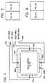
- one embodiment of the present inventionprovides for a computer display device such as a CRT configured so that electrodes 102a-102d overlie perimetrial regions of the screen.
- a computer display devicesuch as a CRT configured so that electrodes 102a-102d overlie perimetrial regions of the screen.
- the electrodes 102a, 102b, 102c, 102dare possible.
- the electrodes 102a, 102b, 102c, 102dare in the form of conductive bus bars positioned along the major portion of each of the four edges of the screen 104, preferably without extending into the corner regions of the screen.
- Conductive wires 106a, 106b, 106c, 106dare in electrical contact with each of the electrodes 102a, 102b, 102c, 102d to provide a communication channel with circuitry described below.
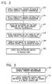
- FIG. 2shows a method used in connection with making a touch screen according to previous devices.
- previous devicesprovided touch screens by placing certain elements on a glass overlay which was later bonded to the front surface of a computer screen such as a CRT, e.g., using a transparent adhesive.
- the glass overlayfirst had a conductive coating applied to its back surface 212 (i.e., the surface which was to contact or to be bonded to the surface of the CRT). This coating was typically provided through an evaporation process, usually in a vacuum oven.
- a similar conductive coatingwas placed on the front of the glass overlay also through an evaporation process 214.
- a further layerwas placed on the back surface of the glass overlay.
- a protective layerwas provided on the back surface.
- it was necessary to place an electrode on the back surfaceoften through a silk screening procedure. It is believed that the back electrode was provided in previous devices as part of a noise reduction technique, i.e., a technique for distinguishing the desired position signal from unwanted signals or noise.
- electrodeswere placed on the front surface of the glass, typically through a silk screening process 218. At this point, previous techniques are believed to have included a step of modifying or changing the shape of the electrodes in order to help linearize the device 220.
- a protective coatingsuch as SiO 2 was placed over at least the front surface of the screen in a process conducted in a vacuum oven 222.
- the process of Fig. 2includes a number of steps which are relatively expensive including evaporation processes which may require processing in a vacuum oven 212, 214, the placing of at least one deposited layer, such as an electrode on the back surface 216 and hand or individual tuning of the electrodes 220.
- Fig. 3depicts a process for providing a touch screen device according to the present invention.
- electrodesare placed directly on the front glass surface of a CRT computer screen.
- the process of Fig. 3could also be used for producing a glass or other transparent overlay for a CRT, by placing the electrodes indirectly on the CRT, it is no longer necessary to include a step of bonding or positioning an overlay over a CRT.
- bondingis used rather than merely positioning over a CRT, since bonding helps provide the necessary strength and robustness and also provides desirable optical qualities.
- the cost of the bonding (positioning) stepis eliminated.
- electrodesare silk screened directly onto the front of the computer screen such as a CRT 312.
- a conductive coatingis applied over the electrodes and the front surface of the screen.
- a protective coatingsuch as SiO 2 is coated on the front of the screen.
- both the conductive coating and the protective coatingare applied in a single vacuum step 314, i.e., without the need to remove the CRT from the vacuum oven between the conductive and protective coatings.
- the electrodescan be made of a number of conductive materials including silver and low temperature melting glass and silver epoxies.
- the conductive coatingis preferably done using materials that can be provided in a substantially transparent form such as indium tin oxide or tin antimony oxide.
- indium tin oxideis used since it can be applied in a single-step process.
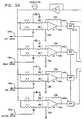
- circuit for dealing with noisegenerally as depicted in Fig. 4 will be discussed.
- the circuit of Fig. 4can be used in connection with a number of touch screen devices, it is particularly useful for the touch screen produced according to the method of Fig. 3, since this method does not involve an electrode on the rear surface of the screen which was a feature believed to have been used by previous devices in connection with noise reduction.
- the touch screenWhen the touch screen is provided with an electric potential at the electrodes 102a, 102b, 102c, 102d, under normal (non-touch) circumstances, the potential that the electrodes will remain constant in time.
- a human touches a portion of the screensuch as with a finger
- a small amount of currentsuch as about 5-10 ⁇ amp per volt of driving potential will flow through the human's body to ground.
- the apparatus of Fig. 4is intended to provide a signal from which the value of the current from one of the electrodes through the human body to ground, can be measured in a relatively noise-free manner.
- the general method used for distinguishing the desired signal from noiseinvolves a relatively high frequency sampling which permits filtering out a lower frequency modulation or "envelope" associated with noise.
- the human bodyis assumed to have electrical characteristics corresponding to a body model 412 having, in series, a first capacitor, resistor and second capacitor. These items are not circuitry items but rather are a model of certain characteristics of the human body.
- the item 412will be the path through the human body from the point where the body touches the touch screen to ground 416.
- One of the lines 106a from the electrode 102a of the touch screenis connected to the positive input of an amplifier such as OP amp 418.
- the OP amphas a relatively high gain, such as a gain of about 2,000 and, in one embodiment, has 127 db common mode rejection.
- a resistorsuch as a 100 kilohm resistor 420 connects the output node 422 to the negative input terminal 424.
- An RC filter 426is provided at the output of the OP amp 418 in order to reduce dV/dt. This eliminates ringing of the filter and is useful in reducing emissions, e.g., in order to comply with regulations such as Federal Communication Commission (FCC) standards.
- FCCFederal Communication Commission
- the signal provided to the electrode 102a(via resistors 430, 432) as well as provided to the negative input of the OP amp 418 (via resistors 434, 436) has a generally sinusoidal form provided at a frequency such as 10 kilohertz 438. Similar circuitry is used to provide signals to (and samples signals at) the other electrodes 102b, 102c, 102d, although the phase of the four signals are preferably offset 90°.
- Noise rejectionis provided by a bandpass filter 440 which samples the amplified electrode signal at a relatively high frequency such as about 100 kilohertz, preferably about 200 kilohertz and more preferably about 250 kilohertz or higher.
- the bandpass filter 440is a fourth order Butterworth filter with a gain of about 20 and a Q factor of about 40.
- a Butterworth filterprovides the advantageous feature of a relatively quick roll-off from the peak and because it performs a high performance-to-cost ratio.
- the Butterworth filtercan be unstable and may, e.g., create ringing.
- the present inventioncan also be used with other types of filters.
- a Bessel filtercan be used which tends to be more stable than a Butterworth filter under transient conditions but does not have as rapid a roll-off.
- Another type of filter that can be usedis an elliptical filter.
- both the filter 440 and the oscillator 438are controlled by a clock signal such as a 20 Mhz signal 442.
- the filterprovides a sampling rate (defining the time frame over which filtering is applied) of at least three times the clock signal rate 442, in one embodiment, a sampling rate of at least 40 kilohertz.
- Other devices for high sampling rate and filteringcan be used such as a fast-acting rectifier or integrator.
- the magnitude of the drive signal 438is set in connection with a gain controller 446.
- One of the functions of the gain controller 446is to accommodate a situation in which there is a rapid change in the environment such as may result from the user touching a grounded metal object, thus changing the effective electrical characteristics of the user's body 412.
- the gain controller 446receives an indication of the magnitude of the signal received from the touch screen, preferably from information provided by the CPU 450, described below. If any of the four signals becomes greater than a predetermined amount, such as greater than 4.5 volts, the system gain is reduced, lowering the drive signal, i.e., the signal 452 output by the oscillator 438. In the embodiment of Fig. 5, the drive signal 452 is attenuated by attenuation signals 516 controlling multiplexer 518.
- Figs. 5 and 6depict one manner of implementing the general configuration of Fig. 4 in a system having four electrodes on a touch screen, as depicted in Fig. 1.
- Fig. 5shows the analog section 512 of circuitry in which each of the drives 106a, 106b, 106c, 106d is connected to the positive input of an OP amp 418a, 418b, 418c, 418d.
- the output of the OP ampoptionally through an RC filter, is connected to a bandpass filter 440a, 440b, 440c, 440d.
- a multiplexer 514selects the outputs from the filters 440a, 440b, 440c, 440d for providing them, one at a time, to an analog to digital converter 612 (Fig. 6).
- the filters 440a, 440b, 440c, 440dare capable of very rapid sampling and, preferably, all four channels are sampled and provided to the A/D converter 612 in less than 800 microseconds, preferably less than 400 microseconds and more preferably, less than 300 microseconds.
- the systemprovides a digital sample of the filtered analog signal at a rate of about 1,000 samples per second (for each of the four electrodes) preferably about 2,500 samples per second, more preferably about 3,000 samples per second or more. Such rapid sampling is used to reduce or eliminate the effects of noise and variation between samples.
- the analog to digital converteris, according to one embodiment, a 12-bit tracking analog to digital converter.
- the central processing unitis controlled by a crystal oscillator 442 which also, by means of dividers 614a, 614b, 614c, 614d, provides clock signals 441 and 552 at 200 Khz and 10 Khz, respectively.
- a power supply 616provides power to the CPU, preferably via power management circuit 614, preferably configured to reset the CPU 450 if V cc falls below 4.75 volts.
- Coupled to the CPUis a communication circuit 620 which can, for example, include optical couplers for converting TTL level to a 20 ⁇ A drive.
- An EPROM memory 622is used for storing utility programs and boot strap programs e.g., for downloading program memories.
- the flash memory 624is used for storing the main program and is preferably non-volatile memory so that the contents remain intact when the power is off.
- the flash memorycan be reloaded or altered via the communications device. In this way the program in the flash memory can be downloaded from a remote location.
- the communication front endcontains optical couplers for serial data in, serial data out, and a global input for remote master reset.
- a CMOS memory 626is used for scratch pad and computation purposes.
- a number of CPUs 450can be used in this regard, although preferably a CPU of the type used in a personal computer environment is preferred.
- the usertouches a portion of the screen, the current flowing from each of the four conductors 102a, 102b, 102c, 102d through the body is a function of the distance from the touch to each of the conductors, respectively.
- the screenhas a substantially equipotential surface.
- the total current flow through the user's bodywould be approximately 8/4 micro amps or 2 micro amps.
- the current from the closer electrodeswill be greater than that from the farther electrodes.
- the amount of current flowing through each of the electrodes through the usercan be used to deduce the position of the touch, as described more fully below.
- the touch currentis measured through an 11.3 ohm resistor so that, converted to voltage, the current becomes 22.6 microvolts per volt of drive voltage.
- the amplifier 418multiplies the voltage by 2,000 and the bandpass filter 440 adds a gain of 20.
- the signal selected by multiplexer 514is provided to buffer amp BA 516 which, in the depicted embodiment, has a gain of 2.
- the systemhas a gain of 80,000.
- the signalis provided to the analog to digital converter.
- the command to convert the analog signal into digital formis synchronized to the output drive oscillator. Synchronization is configured such that when the digital data is obtained, it represents the peak voltage of the touch signal for that channel. Several samples (e.g., four samples per channel) are taken to do an average and to remove any DC value that the sine wave may be riding on.
- the digitized voltages for the four electrodes 102a, 102b, 102c, 102drepresent the voltages at the left, top, right, and bottom electrodes, respectively and are symbolized by V L , V T , V R and V B .
- Y v and X vare related to the vertical and horizontal position of the touch location on the screen, but the relationship, in general, is not linear. In order to obtain the actual position based on the values of Y v and X v a conversion or a linearization procedure is used.
- the linearization procedureis a procedure for converting from one co-ordinate system into another co-ordinate system.
- the conversionis general, non-linear and may be different for each particular touch screen, as well as possibly changing in time due to aging, changes in their environment, etc.
- a method of determining the position of a user's touch on a screena number of measurements are taken of values of Y v and X v at various known locations on the screen. These measurements are then used to determine the parameters of a conversion method for converting the values of Y v and X v into values indicating the location of the touch on the screen.
- the methodbegins by performing a conversion in the opposite direction, i.e., by defining certain locations in the screen location coordinate system and measuring the values of Y v and X v , that result from touches at those predefined locations. These values are then used to calculate the parameters which can be used for converting the coordinate systems in the opposite direction, i.e., from the Y v , X v coordinate system into the screen location coordinate location.
- a number of methodscan be used for converting between the coordinate systems.
- conversion systemswhich are highly accurate require high level of computing resources and/or time. It has been found, however, that the conversion method described below has only moderate computing requirements, but results in a relatively high accuracy or fine-resolution system in which the touch location computed by the system is within a predetermined distance of the actual touch location. In one embodiment, the computed location is within about 1/8 in. of the actual location.
- the systemdetermines whether this is the first power up performed on this system 914 (e.g., by checking a flag). If so, the system performs a calibration procedure 916, described below. Otherwise, a number of housekeeping functions are performed 918 such as clearing registers, checking memories, enabling interrupts and setting up communications. The system then determines whether there is a valid calibration already stored in the system 920. If not, the system then initiates the calibration procedure 916. Otherwise, the system proceeds to set the signal gain to a high level 922, e.g., using the gain controller 446. In the next step, the system performs a check to determine whether the screen is being touched.
- a calibration procedure 916described below. Otherwise, a number of housekeeping functions are performed 918 such as clearing registers, checking memories, enabling interrupts and setting up communications.
- the systemdetermines whether there is a valid calibration already stored in the system 920. If not, the system then initiates the calibration procedure 916. Otherwise, the system proceeds to set the signal gain to a high
- the systemtakes a predetermined number of samples, e.g., four samples on each of the four channels 930 using the high-frequency sampling bandpass filter, A/D converter and other circuitry depicted in Figs. 5 and 6.
- the ambient voltagesare subtracted 932 and the values Y v and X v are calculated according to equations (1) and (2) 934.
- the Y v and X v valuesare then converted to X s and Y s values 936 using equations (3) and (4).
- the position values Y s and X sare then sent to the host computer over communication circuit 620.
- the systemwould be configured to continuously monitor for touches and thus the system would be configured to obtain another location 940 by returning to the state in which the system determines whether any touch of the screen is being made 924. Otherwise, the routine ends 942.
- the systemIn performing a calibration 916, the system first determines whether the monitor is sufficiently warmed up 950 and cycles through successive ten second wait periods 952 until warm up is completed. Next, the CPU 450 sends a request, via communications device 620 to the host computer, requesting the host computer to display instructions to the user on the touch screen 954. During the time when the user is not touching the touch screen, the computer measures the voltages on the four channels 106a, 106b, 106c, 106d and stores these values, e.g., for use in steps 924 and 932. The CPU 450 then requests the host computer to display a touch dot (a dot or other indicium on the touch screen at a predetermined location).
- a touch dota dot or other indicium on the touch screen at a predetermined location.
- the computeralso displays instructions telling the user to touch the screen precisely at the location of the displayed touch dot 958.
- the systemdetermines whether there is a touch 960 and whether the voltage is in the defined limits 962, 964 as described above for steps 924, 926, and 928.
- the ambient voltagesare subtracted 966 and the measured values are stored 968.
- the CPU 450then requests the host computer to place the next dot on the screen 970 in the next predetermined location, unless all the dots have been displayed 972.
- a total of nine touch dots or calibration pointsare used, preferably defining four substantially rectangular and identical quadrants or regions.
- the systemcalculates the parameters a 0 , a 1 , a 2 , a 3 , b 0 , b 1 , b 2 , b 3 , which will be used in equations (3) and (4) 974. This can be done by solving or fitting equations (3) and (4) for each of the variables, a 0 , a 1 , a 2 , a 3 , b 0 , b 1 , b 2 , b 3 . Since nine measurements have been made, this will result in a system of 18 equations and eight unknowns and thus will be overdetermined.
- a "best fit" methodis used to determine values for the unknowns a 0 , a 1 , a 2 , a 3 , b 0 , b 1 , b 2 , b 3 which provide the best fit to the nine measured values of X v and Y v .
- These values of the unknownsare then stored for use in calculating X s and Y s in step 936. The system then returns to step 918, described above.
- the present inventionprovides a number of advantages.
- the present inventionis able to determine the location of a touch on a touch screen with a fine resolution but at a relatively low cost and high rapidity.
- the present inventionreduces costs by eliminating steps such as steps of providing a back electrode and/or back conductive coating and reduces the requirement for the number of steps that must be performed in a separate vacuum chamber processes.
- the present inventioncan also be used in connection with other interactive applications such as locator or navigation devices, automatic teller machines (ATM) in connection with vehicle and/or machinery control devices and the like.
- ATMautomatic teller machines
Landscapes
- Engineering & Computer Science (AREA)
- General Engineering & Computer Science (AREA)
- Theoretical Computer Science (AREA)
- Human Computer Interaction (AREA)
- Physics & Mathematics (AREA)
- General Physics & Mathematics (AREA)
- Position Input By Displaying (AREA)
- User Interface Of Digital Computer (AREA)
Description
- Xs
- is the calculated horizontal distance from the leftedge of the screen.
- Ys
- is the calculated vertical distance from the top edgeof the screen.
Claims (6)
- A touch screen apparatus for sensing contact at apreselected location on a touch screen surface comprising:a cathode ray tube (CRT) screen (104) having an exterior surfacewith an exterior edge at the periphery of the screen;a plurality of bar electrodes (102a-102d) positioned substantiallynear the exterior edge of the screen;a driver (512, 612) having a plurality of channels, each channelconnected to one of the bar electrodes, for providing voltages to thebar electrodes, and for providing signals indicating contact on thesurface, the signals resulting from a current flow through a touchingapparatus contacting the surface, the signals being a function ofa difference in voltage level at a first time t1, when there is no contactand at a second time t2, coincident with the time of contact; andposition determining means (450, 622, 624, 626) for receiving thesignals from the channels and evaluating the signals to identify theposition of the touch relative to the plurality of bar electrodes,characterizedby the electrodes being disposed directly on the exterior surface ofthe CRT screen.
- The touch screen apparatus of claim 1, wherein theexterior surface is substantially rectangular, furthercomprising:a first bar electrode (102b) positioned substantially parallel to andnear a top edge of the screen;a second bar electrode (102d) positioned substantially parallel toand near a bottom edge of the screen;a third bar electrode (102a) positioned substantially parallel to andnear a left edge of the screen;a fourth bar electrode (102c) positioned substantially parallel to andnear a right edge of the screen;the first and second bar electrodes functioning as a pair to determinea relative vertical position of the touch; andthe third and fourth bar electrodes functioning as a pair to determinea relative horizontal position of the touch.
- The touch screen apparatus of claim 2, wherein therelative vertical position Pv of the touch is determinedas a function of voltage measured at the first bar electrodes(VT), and voltage measured at the second barelectrode (VB), as follows:
- The touch screen apparatus of claim 1, 2 or 3,
wherein the driver further comprises:an oscillator (438) connected to each of the channels for setting uptiming intervals for digitizing analog signals generated by each of thechannels;amplifier means (418a-d) in each of the channels having a first input(424), a second input (106), and an output (422), the first inputbeing connected to the oscillator, the second input being connectedto the oscillator and to a corresponding bar electrode, such thatwhen no touch is present, the amplifier means is at equilibriumwith a substantially constant amplifier output signal, and when atouch occurs on the surface, a current flows from the screenthrough the touching apparatus, causing a voltage drop across theinputs on the amplifier means and a resulting amplifier output signal;a filter (440a-d) in each of the channels for receiving the resultingamplifier output signal from the amplifier means and substantiallypassing signals greater than a predetermined frequency; and ananalog-to-digital converter (612) for sampling the filtered outputsignal at least a predetermined sampling rate. - The touch screen apparatus of claim 4, wherein thedriver further comprises a clock (442) connected to thefilter in each of the channels for synchronizing a samplingrate of each filter.
- The touch screen apparatus of claim 5,
wherein the filter in each channel samples at a rate ofat least three times per cycle of the clock signal, and/or
wherein the filter samples at a rate configured to enablea determination of an AC component of amplitude,
an AC component of phase, and a DC component,
said sampling rate being preferably at least 40 KHz,
and/or
wherein a touch is determined to have occurred upon apeak of a sampled signal from the filter being above athreshold level, the sampled signal being represented bythe following equation:S represents the sampled signal;A is the amplitude of the sampled signal;ω is the phase angle;ø is the phase of the sampled signal;T is the amplitude of the current flowing through the touchapparatus.
Applications Claiming Priority (3)
| Application Number | Priority Date | Filing Date | Title |
|---|---|---|---|
| US08/294,227US6476798B1 (en) | 1994-08-22 | 1994-08-22 | Reduced noise touch screen apparatus and method |
| US294227 | 1994-08-22 | ||
| EP95111767AEP0698858B1 (en) | 1994-08-22 | 1995-07-26 | Reduced noise touch screen apparatus |
Related Parent Applications (2)
| Application Number | Title | Priority Date | Filing Date |
|---|---|---|---|
| EP95111767.0Division | 1995-07-26 | ||
| EP95111767ADivisionEP0698858B1 (en) | 1994-08-22 | 1995-07-26 | Reduced noise touch screen apparatus |
Publications (3)
| Publication Number | Publication Date |
|---|---|
| EP1158393A2 EP1158393A2 (en) | 2001-11-28 |
| EP1158393A3 EP1158393A3 (en) | 2002-01-02 |
| EP1158393B1true EP1158393B1 (en) | 2005-05-18 |
Family
ID=23132443
Family Applications (3)
| Application Number | Title | Priority Date | Filing Date |
|---|---|---|---|
| EP95111767AExpired - LifetimeEP0698858B1 (en) | 1994-08-22 | 1995-07-26 | Reduced noise touch screen apparatus |
| EP01124517AWithdrawnEP1174788A1 (en) | 1994-08-22 | 1995-07-26 | Reduced noise touch screen apparatus and method |
| EP01121197AExpired - LifetimeEP1158393B1 (en) | 1994-08-22 | 1995-07-26 | Reduced noise touch screen |
Family Applications Before (2)
| Application Number | Title | Priority Date | Filing Date |
|---|---|---|---|
| EP95111767AExpired - LifetimeEP0698858B1 (en) | 1994-08-22 | 1995-07-26 | Reduced noise touch screen apparatus |
| EP01124517AWithdrawnEP1174788A1 (en) | 1994-08-22 | 1995-07-26 | Reduced noise touch screen apparatus and method |
Country Status (10)
| Country | Link |
|---|---|
| US (3) | US6476798B1 (en) |
| EP (3) | EP0698858B1 (en) |
| JP (1) | JPH0876924A (en) |
| KR (1) | KR960008494A (en) |
| AU (1) | AU718499B2 (en) |
| BR (1) | BR9503742A (en) |
| CA (1) | CA2154648C (en) |
| DE (2) | DE69526471T2 (en) |
| ES (2) | ES2241727T3 (en) |
| ZA (1) | ZA956964B (en) |
Families Citing this family (240)
| Publication number | Priority date | Publication date | Assignee | Title |
|---|---|---|---|---|
| US20030161889A1 (en)* | 1984-03-16 | 2003-08-28 | Reid Robert H. | Vaccines against diseases caused by enteropathogenic organisms using antigens encapsulated within biodegradable-biocompatible microspheres |
| US5841427A (en)* | 1995-12-22 | 1998-11-24 | Symbios, Inc. | Method and apparatus for canceling an offset signal in an electrostatic digitizing tablet |
| US6208329B1 (en) | 1996-08-13 | 2001-03-27 | Lsi Logic Corporation | Supplemental mouse button emulation system, method and apparatus for a coordinate based data input device |
| JP3484355B2 (en)* | 1998-09-28 | 2004-01-06 | オムロンヘルスケア株式会社 | Biological detector |
| TW408277B (en)* | 1996-11-15 | 2000-10-11 | Alps Electric Co Ltd | Small current detector circuit and locator device using the same |
| US20060180653A1 (en)* | 1997-05-07 | 2006-08-17 | Diebold, Incorporated | ATM system and method |
| US5977957A (en)* | 1997-05-22 | 1999-11-02 | Ericsson Inc. | Adaptive sampling of touch screen input |
| US6135884A (en)* | 1997-08-08 | 2000-10-24 | International Game Technology | Gaming machine having secondary display for providing video content |
| KR100293435B1 (en) | 1997-10-31 | 2001-08-07 | 구본준, 론 위라하디락사 | Position sensable liquid crystal and moethod for fabricating the same |
| KR100595922B1 (en) | 1998-01-26 | 2006-07-05 | 웨인 웨스터만 | Method and apparatus for integrating manual input |
| US8640946B1 (en)* | 1998-04-17 | 2014-02-04 | Diebold Self-Service Systems, Division Of Diebold, Incorporated | ATM that allows a user to select a desired transaction by touch dragging a displayed icon that represents the desired transaction |
| US8651373B1 (en)* | 1998-04-17 | 2014-02-18 | Diebold Self-Service Systems, Division Of Diebold, Incorporated | ATM that allows a user to select a desired transaction by touch dragging a displayed icon that represents the desired transaction |
| US7749081B1 (en)* | 1999-04-28 | 2010-07-06 | Igt | Method and apparatus for displaying player tracking information on an electronic gaming machine display |
| KR100473592B1 (en)* | 1999-07-19 | 2005-03-07 | 엘지.필립스 엘시디 주식회사 | A digitizer |
| US6305123B1 (en)* | 1999-09-17 | 2001-10-23 | Meritor Light Vehicle Systems, Llc | Obstruction sensing a signal transmitted across window |
| JP2001175417A (en)* | 1999-12-22 | 2001-06-29 | Nec Corp | Inter-electrode short circuit preventing structure for resistance film type touch panel |
| US7950999B2 (en)* | 2004-09-16 | 2011-05-31 | Bally Gaming, Inc. | User interface system and method for a gaming machine |
| US9235955B2 (en)* | 2000-12-22 | 2016-01-12 | Bally Gaming, Inc. | Universal game monitoring unit and system |
| US8414381B2 (en)* | 1999-12-30 | 2013-04-09 | Bally Gaming, Inc. | Method for remapping a game wheel |
| KR20010007754A (en)* | 2000-08-12 | 2001-02-05 | 윤은혁 | The manufacturing mathod of bobbin for embroidery machine |
| US6942571B1 (en) | 2000-10-16 | 2005-09-13 | Bally Gaming, Inc. | Gaming device with directional and speed control of mechanical reels using touch screen |
| US8241124B2 (en) | 2000-10-16 | 2012-08-14 | Bally Gaming, Inc. | Gaming machine having a curved display with a video switcher and touch router system |
| US8550912B2 (en) | 2000-10-16 | 2013-10-08 | Bally Gaming, Inc. | Gaming machine having a display and speaker system with light piping material |
| US8012021B2 (en) | 2000-10-16 | 2011-09-06 | Bally Gaming, Inc. | Gaming machine having a molded curved display |
| US8678902B2 (en) | 2005-09-07 | 2014-03-25 | Bally Gaming, Inc. | System gaming |
| DE10064921A1 (en)* | 2000-12-23 | 2002-07-18 | Siemens Ag | Liquid crystal display with a heater |
| US6661408B2 (en)* | 2001-03-23 | 2003-12-09 | Eturbotouch Technology Inc. | Touch screen capable of isolating noise signals |
| US8480466B2 (en) | 2001-03-27 | 2013-07-09 | Igt | Method and apparatus for previewing a game |
| US7918738B2 (en) | 2001-03-27 | 2011-04-05 | Igt | Interactive game playing preferences |
| US8025568B2 (en) | 2001-03-29 | 2011-09-27 | Wms Gaming Inc. | Gaming machine with an overhanging touch screen |
| EP1401546A4 (en) | 2001-06-15 | 2006-11-02 | Walker Digital Llc | METHOD AND DEVICE FOR PLANNING AND INDIVIDUALIZING A GAME EXPERIENCE |
| US7024723B2 (en)* | 2001-06-15 | 2006-04-11 | Headwaters R&D, Inc. | Duster cleaning member for a vacuum cleaner |
| US6488981B1 (en)* | 2001-06-20 | 2002-12-03 | 3M Innovative Properties Company | Method of manufacturing a touch screen panel |
| US20030013522A1 (en)* | 2001-07-10 | 2003-01-16 | Muir David Hugh | Automatic electronic display alignment |
| US7611409B2 (en)* | 2001-09-20 | 2009-11-03 | Igt | Method and apparatus for registering a mobile device with a gaming machine |
| US20050143169A1 (en)* | 2001-09-20 | 2005-06-30 | Igt | Direction interfaces and services on a gaming machine |
| US6712698B2 (en) | 2001-09-20 | 2004-03-30 | Igt | Game service interfaces for player tracking touch screen display |
| US7699703B2 (en)* | 2001-09-20 | 2010-04-20 | Igt | Method and apparatus for registering a mobile device with a gaming machine |
| US20050227769A1 (en)* | 2001-09-28 | 2005-10-13 | Morrow James W | Gaming device network managing system and method |
| US20070111799A1 (en)* | 2001-09-28 | 2007-05-17 | Robb Harold K | Controlled access switch |
| US8342935B1 (en) | 2001-09-28 | 2013-01-01 | Bally Gaming, Inc. | Integrated display and input system |
| US20060287098A1 (en)* | 2001-09-28 | 2006-12-21 | Morrow James W | System and method for gaming-content configuration and management system |
| US20070117633A1 (en)* | 2001-09-28 | 2007-05-24 | Hamilton Garry L | Store and Forward Patron Account Messaging System |
| US8708826B2 (en)* | 2001-09-28 | 2014-04-29 | Bally Gaming, Inc. | Controlled access switch |
| US7158121B2 (en)* | 2001-10-19 | 2007-01-02 | American Standard International Inc. | Enhanced touch-screen display system |
| US6977646B1 (en)* | 2001-11-30 | 2005-12-20 | 3M Innovative Properties Co. | Touch screen calibration system and method |
| JP4004799B2 (en)* | 2002-01-09 | 2007-11-07 | 株式会社ワコム | Current sending circuit to sensor coil of coordinate input device |
| US7037191B2 (en) | 2002-05-01 | 2006-05-02 | Igt | Gaming device having multiple pay slots |
| US7815507B2 (en) | 2004-06-18 | 2010-10-19 | Igt | Game machine user interface using a non-contact eye motion recognition device |
| US8460103B2 (en) | 2004-06-18 | 2013-06-11 | Igt | Gesture controlled casino gaming system |
| US9082260B2 (en) | 2004-09-16 | 2015-07-14 | Bally Gaming, Inc. | Networked gaming system communication protocols and methods |
| US7789756B2 (en) | 2002-09-13 | 2010-09-07 | Igt | Wagering gaming device having simulated control of movement of game functional elements |
| US8992326B2 (en) | 2006-09-06 | 2015-03-31 | Bally Gaming, Inc. | Networked gaming system communication protocols and methods |
| US8535158B2 (en) | 2004-09-16 | 2013-09-17 | Bally Gaming, Inc. | Networked gaming system communication protocols and methods |
| US8529349B2 (en) | 2004-09-16 | 2013-09-10 | Bally Gaming, Inc. | Networked gaming system communication protocols and methods |
| US8986122B2 (en) | 2002-09-13 | 2015-03-24 | Bally Gaming, Inc. | Networked gaming system communication protocols and methods |
| US9117342B2 (en) | 2004-09-16 | 2015-08-25 | Bally Gaming, Inc. | Networked gaming system communication protocols and methods |
| US8568237B2 (en) | 2004-09-16 | 2013-10-29 | Bally Gaming, Inc. | Networked gaming system communication protocols and methods |
| US7331868B2 (en)* | 2002-09-13 | 2008-02-19 | Igt | Wagering gaming device providing physical stimulation responses to various components of the gaming device |
| US7180508B2 (en)* | 2002-09-17 | 2007-02-20 | Tyco Electronics Corporation | Dynamic corrections for a non-linear touchscreen |
| JP4383730B2 (en)* | 2002-10-22 | 2009-12-16 | アルプス電気株式会社 | Electronic device having touch sensor |
| US7075523B2 (en)* | 2002-10-28 | 2006-07-11 | Semtech New York Corporation | Data acquisition from capacitive touch pad |
| US7362313B2 (en)* | 2003-01-17 | 2008-04-22 | 3M Innovative Properties Company | Touch simulation system and method |
| US8784195B1 (en) | 2003-03-05 | 2014-07-22 | Bally Gaming, Inc. | Authentication system for gaming machines |
| US7312788B2 (en) | 2003-03-11 | 2007-12-25 | Fraunhofer-Gesellschaft Zur Foerderung Der Angewandten Forschung E.V. | Gesture-based input device for a user interface of a computer |
| EP1457863A3 (en)* | 2003-03-11 | 2007-02-21 | Fraunhofer-Gesellschaft zur Förderung der angewandten Forschung e.V. | Gesture-based input device for a user interface of a computer |
| US7883421B2 (en)* | 2003-03-17 | 2011-02-08 | Igt | Gaming apparatus having a display with a conductive coating |
| CA2443206A1 (en) | 2003-09-23 | 2005-03-23 | Ignis Innovation Inc. | Amoled display backplanes - pixel driver circuits, array architecture, and external compensation |
| US8512144B2 (en) | 2003-10-20 | 2013-08-20 | Tipping Point Group, Llc | Method and apparatus for providing secondary gaming machine functionality |
| US7327349B2 (en)* | 2004-03-02 | 2008-02-05 | Microsoft Corporation | Advanced navigation techniques for portable devices |
| US7663606B2 (en)* | 2004-03-19 | 2010-02-16 | Igt | Apparatus and method for configuring a touch screen |
| US7855717B2 (en)* | 2004-03-19 | 2010-12-21 | Igt | Touch screen apparatus and method |
| DE102004025265A1 (en) | 2004-05-19 | 2005-12-15 | Siemens Ag | Operating element for a device, in particular a medical device |
| US8684839B2 (en) | 2004-06-18 | 2014-04-01 | Igt | Control of wager-based game using gesture recognition |
| US7798902B2 (en)* | 2004-06-25 | 2010-09-21 | Wms Gaming Inc. | Gaming machine with an improved touch screen assembly |
| CA2472671A1 (en) | 2004-06-29 | 2005-12-29 | Ignis Innovation Inc. | Voltage-programming scheme for current-driven amoled displays |
| US7942744B2 (en) | 2004-08-19 | 2011-05-17 | Igt | Virtual input system |
| US9022866B2 (en)* | 2004-09-16 | 2015-05-05 | Bally Gaming, Inc. | User interface system and system-controlled bonus system |
| US10803694B2 (en) | 2004-09-16 | 2020-10-13 | Sg Gaming, Inc. | Player gaming console, gaming machine, networked gaming system |
| US7905780B2 (en)* | 2004-09-16 | 2011-03-15 | Bally Gaming International, Inc. | User interface system and method |
| US8684822B2 (en)* | 2004-09-16 | 2014-04-01 | Bally Gaming, Inc. | System-level bonus game and related methods |
| US8602882B2 (en) | 2004-10-04 | 2013-12-10 | Igt | Jackpot interfaces and services on a gaming machine |
| US7862427B2 (en)* | 2004-10-04 | 2011-01-04 | Igt | Wide area progressive jackpot system and methods |
| US20060125781A1 (en)* | 2004-12-15 | 2006-06-15 | Sachs Todd S | Sliding structure location on a pointing device corrected for non-linearity of measured differential |
| US9275579B2 (en) | 2004-12-15 | 2016-03-01 | Ignis Innovation Inc. | System and methods for extraction of threshold and mobility parameters in AMOLED displays |
| TWI402790B (en) | 2004-12-15 | 2013-07-21 | Ignis Innovation Inc | Method and system for programming, calibrating and driving a light-emitting element display |
| US9171500B2 (en) | 2011-05-20 | 2015-10-27 | Ignis Innovation Inc. | System and methods for extraction of parasitic parameters in AMOLED displays |
| US9280933B2 (en) | 2004-12-15 | 2016-03-08 | Ignis Innovation Inc. | System and methods for extraction of threshold and mobility parameters in AMOLED displays |
| US10012678B2 (en) | 2004-12-15 | 2018-07-03 | Ignis Innovation Inc. | Method and system for programming, calibrating and/or compensating, and driving an LED display |
| US10013907B2 (en) | 2004-12-15 | 2018-07-03 | Ignis Innovation Inc. | Method and system for programming, calibrating and/or compensating, and driving an LED display |
| US8576217B2 (en) | 2011-05-20 | 2013-11-05 | Ignis Innovation Inc. | System and methods for extraction of threshold and mobility parameters in AMOLED displays |
| US9799246B2 (en) | 2011-05-20 | 2017-10-24 | Ignis Innovation Inc. | System and methods for extraction of threshold and mobility parameters in AMOLED displays |
| US20140111567A1 (en) | 2005-04-12 | 2014-04-24 | Ignis Innovation Inc. | System and method for compensation of non-uniformities in light emitting device displays |
| CA2496642A1 (en)* | 2005-02-10 | 2006-08-10 | Ignis Innovation Inc. | Fast settling time driving method for organic light-emitting diode (oled) displays based on current programming |
| US20060189367A1 (en)* | 2005-02-22 | 2006-08-24 | Igt | Harm minimization interfaces and services on a gaming machine |
| US7892096B2 (en)* | 2005-02-22 | 2011-02-22 | Wms Gaming Inc. | Gaming machine with configurable button panel |
| CN1838051A (en)* | 2005-03-25 | 2006-09-27 | 鸿富锦精密工业(深圳)有限公司 | Touch Sensing Device |
| JP5355080B2 (en) | 2005-06-08 | 2013-11-27 | イグニス・イノベイション・インコーポレーテッド | Method and system for driving a light emitting device display |
| US20070034423A1 (en)* | 2005-08-12 | 2007-02-15 | Rebeschi Thomas J | Touch screen having reduced susceptibility to radio frequency interference |
| US9552686B2 (en) | 2005-09-02 | 2017-01-24 | Igt | Video and mechanical spinning bonus wheel |
| US8678901B1 (en) | 2005-09-07 | 2014-03-25 | Bally Gaming | System gaming |
| US8840462B2 (en)* | 2005-09-07 | 2014-09-23 | Bally Gaming, Inc. | Tournament bonus awards and related methods |
| US20080220879A1 (en)* | 2005-09-07 | 2008-09-11 | Bally Gaming, Inc. | Trusted Cabinet Identification Method |
| US20080254883A1 (en)* | 2005-09-07 | 2008-10-16 | Bally Gaming, Inc. | Tournament bonus awards |
| US20080220880A1 (en)* | 2005-09-07 | 2008-09-11 | Bally Gaming, Inc. | Trusted Cabinet Identification System |
| CA2518276A1 (en) | 2005-09-13 | 2007-03-13 | Ignis Innovation Inc. | Compensation technique for luminance degradation in electro-luminance devices |
| US8992304B2 (en) | 2006-04-13 | 2015-03-31 | Igt | Methods and systems for tracking an event of an externally controlled interface |
| US10026255B2 (en) | 2006-04-13 | 2018-07-17 | Igt | Presentation of remotely-hosted and locally rendered content for gaming systems |
| US8784196B2 (en) | 2006-04-13 | 2014-07-22 | Igt | Remote content management and resource sharing on a gaming machine and method of implementing same |
| US9028329B2 (en) | 2006-04-13 | 2015-05-12 | Igt | Integrating remotely-hosted and locally rendered content on a gaming device |
| TW200746022A (en) | 2006-04-19 | 2007-12-16 | Ignis Innovation Inc | Stable driving scheme for active matrix displays |
| US8100753B2 (en) | 2006-05-23 | 2012-01-24 | Bally Gaming, Inc. | Systems, methods and articles to facilitate playing card games with selectable odds |
| US8052519B2 (en) | 2006-06-08 | 2011-11-08 | Bally Gaming, Inc. | Systems, methods and articles to facilitate lockout of selectable odds/advantage in playing card games |
| CA2556961A1 (en) | 2006-08-15 | 2008-02-15 | Ignis Innovation Inc. | Oled compensation technique based on oled capacitance |
| US7874923B2 (en)* | 2006-09-27 | 2011-01-25 | Igt | Multiple touchscreen sensors on a monolithic structure |
| US20090156303A1 (en) | 2006-11-10 | 2009-06-18 | Igt | Bonusing Architectures in a Gaming Environment |
| US9311774B2 (en) | 2006-11-10 | 2016-04-12 | Igt | Gaming machine with externally controlled content display |
| US8547114B2 (en) | 2006-11-14 | 2013-10-01 | Cypress Semiconductor Corporation | Capacitance to code converter with sigma-delta modulator |
| US8269727B2 (en) | 2007-01-03 | 2012-09-18 | Apple Inc. | Irregular input identification |
| US7855718B2 (en) | 2007-01-03 | 2010-12-21 | Apple Inc. | Multi-touch input discrimination |
| US8130203B2 (en) | 2007-01-03 | 2012-03-06 | Apple Inc. | Multi-touch input discrimination |
| US7643011B2 (en)* | 2007-01-03 | 2010-01-05 | Apple Inc. | Noise detection in multi-touch sensors |
| US7852325B2 (en)* | 2007-01-05 | 2010-12-14 | Apple Inc. | RF pulse synchronization for data acquisition operations |
| US7999793B2 (en)* | 2007-03-16 | 2011-08-16 | Texas Instruments Incorporated | Median and mean coherent filter and method for eliminating noise in touch screen controller |
| US20090019188A1 (en)* | 2007-07-11 | 2009-01-15 | Igt | Processing input for computing systems based on the state of execution |
| GB2451267A (en)* | 2007-07-26 | 2009-01-28 | Harald Philipp | Capacitive position sensor |
| US8004165B2 (en)* | 2007-09-05 | 2011-08-23 | Seiko Epson Corporation | Tuning fork oscillating piece, tuning fork oscillator, and acceleration sensor |
| US8087983B2 (en)* | 2007-10-13 | 2012-01-03 | Douglas Ronald Longway | Apparatus and methodology for electronic table game system |
| US8920236B2 (en) | 2007-11-02 | 2014-12-30 | Bally Gaming, Inc. | Game related systems, methods, and articles that combine virtual and physical elements |
| US8525798B2 (en) | 2008-01-28 | 2013-09-03 | Cypress Semiconductor Corporation | Touch sensing |
| US8418046B2 (en)* | 2008-02-13 | 2013-04-09 | Apple Inc. | Data signal handling circuitry and methods with error analysis capabilities |
| US8358142B2 (en) | 2008-02-27 | 2013-01-22 | Cypress Semiconductor Corporation | Methods and circuits for measuring mutual and self capacitance |
| US8319505B1 (en) | 2008-10-24 | 2012-11-27 | Cypress Semiconductor Corporation | Methods and circuits for measuring mutual and self capacitance |
| US9104273B1 (en)* | 2008-02-29 | 2015-08-11 | Cypress Semiconductor Corporation | Multi-touch sensing method |
| US8251803B2 (en) | 2008-04-30 | 2012-08-28 | Bally Gaming, Inc. | Overlapping progressive jackpots |
| US20090275407A1 (en)* | 2008-04-30 | 2009-11-05 | Bally Gaming, Inc. | Virtualization for gaming devices |
| US20090322710A1 (en)* | 2008-06-30 | 2009-12-31 | Finepoint Innovations, Inc. | Extent calibration for absolute input sensors |
| US8321174B1 (en) | 2008-09-26 | 2012-11-27 | Cypress Semiconductor Corporation | System and method to measure capacitance of capacitive sensor array |
| US8137176B2 (en) | 2008-10-30 | 2012-03-20 | Bally Gaming, Inc. | Configurable displays used, for example in gaming machines |
| TWI405112B (en)* | 2008-11-07 | 2013-08-11 | Au Optronics Corp | Sensing apparatus for capacitive touch panel |
| US9039529B2 (en) | 2008-11-14 | 2015-05-26 | Bally Gaming, Inc. | Gaming machine having a display and speaker system with light piping material |
| US20100214265A1 (en)* | 2009-02-26 | 2010-08-26 | Ng Shek-Wai | Touch sensitive input device |
| US9384698B2 (en) | 2009-11-30 | 2016-07-05 | Ignis Innovation Inc. | System and methods for aging compensation in AMOLED displays |
| CA2688870A1 (en) | 2009-11-30 | 2011-05-30 | Ignis Innovation Inc. | Methode and techniques for improving display uniformity |
| CA2669367A1 (en) | 2009-06-16 | 2010-12-16 | Ignis Innovation Inc | Compensation technique for color shift in displays |
| US10319307B2 (en) | 2009-06-16 | 2019-06-11 | Ignis Innovation Inc. | Display system with compensation techniques and/or shared level resources |
| US9311859B2 (en) | 2009-11-30 | 2016-04-12 | Ignis Innovation Inc. | Resetting cycle for aging compensation in AMOLED displays |
| US8723827B2 (en) | 2009-07-28 | 2014-05-13 | Cypress Semiconductor Corporation | Predictive touch surface scanning |
| TWI400646B (en)* | 2009-08-12 | 2013-07-01 | Htc Corp | Method for detecting pressure of touch sensing element and electronic device using the same |
| KR101657215B1 (en)* | 2009-09-08 | 2016-09-19 | 삼성디스플레이 주식회사 | Display device including touch panel device and coupling-noise elliminating method |
| US8031094B2 (en)* | 2009-09-11 | 2011-10-04 | Apple Inc. | Touch controller with improved analog front end |
| EP2491478A4 (en)* | 2009-10-20 | 2014-07-23 | Cypress Semiconductor Corp | Method and apparatus for reducing coupled noise influence in touch screen controllers. |
| US10996258B2 (en) | 2009-11-30 | 2021-05-04 | Ignis Innovation Inc. | Defect detection and correction of pixel circuits for AMOLED displays |
| US8803417B2 (en) | 2009-12-01 | 2014-08-12 | Ignis Innovation Inc. | High resolution pixel architecture |
| CA2687631A1 (en) | 2009-12-06 | 2011-06-06 | Ignis Innovation Inc | Low power driving scheme for display applications |
| CA2692097A1 (en) | 2010-02-04 | 2011-08-04 | Ignis Innovation Inc. | Extracting correlation curves for light emitting device |
| US10163401B2 (en) | 2010-02-04 | 2018-12-25 | Ignis Innovation Inc. | System and methods for extracting correlation curves for an organic light emitting device |
| US9881532B2 (en) | 2010-02-04 | 2018-01-30 | Ignis Innovation Inc. | System and method for extracting correlation curves for an organic light emitting device |
| US10176736B2 (en) | 2010-02-04 | 2019-01-08 | Ignis Innovation Inc. | System and methods for extracting correlation curves for an organic light emitting device |
| US10089921B2 (en) | 2010-02-04 | 2018-10-02 | Ignis Innovation Inc. | System and methods for extracting correlation curves for an organic light emitting device |
| US20140313111A1 (en) | 2010-02-04 | 2014-10-23 | Ignis Innovation Inc. | System and methods for extracting correlation curves for an organic light emitting device |
| US9245419B2 (en) | 2010-02-10 | 2016-01-26 | Leap Forward Gaming, Inc. | Lottery games on an electronic gaming machine |
| CA2696778A1 (en)* | 2010-03-17 | 2011-09-17 | Ignis Innovation Inc. | Lifetime, uniformity, parameter extraction methods |
| JP2011248768A (en)* | 2010-05-28 | 2011-12-08 | Sony Corp | Information processor, information processing system and program |
| US8508493B2 (en) | 2010-06-21 | 2013-08-13 | Pixart Imaging Inc. | Reduction of electromagnetic interference in a capacitive touchscreen system |
| US8907991B2 (en) | 2010-12-02 | 2014-12-09 | Ignis Innovation Inc. | System and methods for thermal compensation in AMOLED displays |
| WO2012108911A1 (en) | 2011-02-07 | 2012-08-16 | Cypress Semiconductor Corporation | Noise filtering devices, systems and methods for capacitance sensing devices |
| US9323385B2 (en) | 2011-04-05 | 2016-04-26 | Parade Technologies, Ltd. | Noise detection for a capacitance sensing panel |
| US9170322B1 (en) | 2011-04-05 | 2015-10-27 | Parade Technologies, Ltd. | Method and apparatus for automating noise reduction tuning in real time |
| US9092098B2 (en) | 2011-04-19 | 2015-07-28 | Cypress Semiconductor Corporation | Method and apparatus to improve noise immunity of a touch sense array |
| US9530349B2 (en) | 2011-05-20 | 2016-12-27 | Ignis Innovations Inc. | Charged-based compensation and parameter extraction in AMOLED displays |
| US9466240B2 (en) | 2011-05-26 | 2016-10-11 | Ignis Innovation Inc. | Adaptive feedback system for compensating for aging pixel areas with enhanced estimation speed |
| US9773439B2 (en) | 2011-05-27 | 2017-09-26 | Ignis Innovation Inc. | Systems and methods for aging compensation in AMOLED displays |
| US9875607B2 (en) | 2011-07-13 | 2018-01-23 | Igt | Methods and apparatus for providing secure logon to a gaming machine using a mobile device |
| TWI469025B (en)* | 2011-08-25 | 2015-01-11 | Touch panel and its dynamic drive control method | |
| US20190272704A1 (en) | 2011-09-09 | 2019-09-05 | Igt | Redemption of virtual tickets using a portable electronic device |
| US9367835B2 (en) | 2011-09-09 | 2016-06-14 | Igt | Retrofit devices for providing virtual ticket-in and ticket-out on a gaming machine |
| US10121318B2 (en) | 2011-09-09 | 2018-11-06 | Igt | Bill acceptors and printers for providing virtual ticket-in and ticket-out on a gaming machine |
| US8613659B2 (en) | 2011-09-09 | 2013-12-24 | Igt | Virtual ticket-in and ticket-out on a gaming machine |
| US10297105B2 (en) | 2011-09-09 | 2019-05-21 | Igt | Redemption of virtual tickets using a portable electronic device |
| US8333657B1 (en) | 2011-09-26 | 2012-12-18 | Igt | Gaming system, gaming device and method for displaying multiple concurrent games using dynamic focal points |
| US9524609B2 (en) | 2011-09-30 | 2016-12-20 | Igt | Gaming system, gaming device and method for utilizing mobile devices at a gaming establishment |
| CN102368192A (en)* | 2011-09-30 | 2012-03-07 | 苏州瀚瑞微电子有限公司 | Structure of two-dimensional capacitance sensor and positioning method thereof |
| US10089924B2 (en) | 2011-11-29 | 2018-10-02 | Ignis Innovation Inc. | Structural and low-frequency non-uniformity compensation |
| US9324268B2 (en) | 2013-03-15 | 2016-04-26 | Ignis Innovation Inc. | Amoled displays with multiple readout circuits |
| US8613668B2 (en) | 2011-12-22 | 2013-12-24 | Igt | Directional wireless communication |
| US8937632B2 (en) | 2012-02-03 | 2015-01-20 | Ignis Innovation Inc. | Driving system for active-matrix displays |
| KR20130098459A (en) | 2012-02-28 | 2013-09-05 | 삼성전자주식회사 | Noise spectrum estimator and touch screen device including the same |
| US8876596B2 (en) | 2012-02-29 | 2014-11-04 | Igt | Virtualized magnetic player card |
| US9311769B2 (en) | 2012-03-28 | 2016-04-12 | Igt | Emailing or texting as communication between mobile device and EGM |
| US9747834B2 (en) | 2012-05-11 | 2017-08-29 | Ignis Innovation Inc. | Pixel circuits including feedback capacitors and reset capacitors, and display systems therefore |
| US8922544B2 (en) | 2012-05-23 | 2014-12-30 | Ignis Innovation Inc. | Display systems with compensation for line propagation delay |
| US9412227B2 (en) | 2012-07-11 | 2016-08-09 | Igt | Method and apparatus for offering a mobile device version of an electronic gaming machine game at the electronic gaming machine |
| CN102841268B (en)* | 2012-07-20 | 2016-03-16 | 敦泰科技有限公司 | A kind of capacitance plate noise detecting method and system |
| US9213052B2 (en) | 2012-08-01 | 2015-12-15 | Parade Technologies, Ltd. | Peak detection schemes for touch position detection |
| US9442597B2 (en) | 2012-10-19 | 2016-09-13 | Apple Inc. | Sensor-based ESD detection |
| US9786223B2 (en) | 2012-12-11 | 2017-10-10 | Ignis Innovation Inc. | Pixel circuits for AMOLED displays |
| US9336717B2 (en) | 2012-12-11 | 2016-05-10 | Ignis Innovation Inc. | Pixel circuits for AMOLED displays |
| CN108665836B (en) | 2013-01-14 | 2021-09-03 | 伊格尼斯创新公司 | Method and system for compensating for deviations of a measured device current from a reference current |
| US9830857B2 (en) | 2013-01-14 | 2017-11-28 | Ignis Innovation Inc. | Cleaning common unwanted signals from pixel measurements in emissive displays |
| US9442598B2 (en)* | 2013-02-08 | 2016-09-13 | Synaptics Incorporated | Detecting interference in an input device having electrodes |
| EP3043338A1 (en) | 2013-03-14 | 2016-07-13 | Ignis Innovation Inc. | Re-interpolation with edge detection for extracting an aging pattern for amoled displays |
| WO2014174427A1 (en) | 2013-04-22 | 2014-10-30 | Ignis Innovation Inc. | Inspection system for oled display panels |
| WO2014209333A1 (en)* | 2013-06-27 | 2014-12-31 | Schneider Electric It Corporation | Busbar current sensor |
| CN105474296B (en) | 2013-08-12 | 2017-08-18 | 伊格尼斯创新公司 | A method and device for driving a display using image data |
| US10042446B2 (en) | 2013-08-13 | 2018-08-07 | Samsung Electronics Company, Ltd. | Interaction modes for object-device interactions |
| US10141929B2 (en) | 2013-08-13 | 2018-11-27 | Samsung Electronics Company, Ltd. | Processing electromagnetic interference signal using machine learning |
| US10073578B2 (en) | 2013-08-13 | 2018-09-11 | Samsung Electronics Company, Ltd | Electromagnetic interference signal detection |
| US10101869B2 (en) | 2013-08-13 | 2018-10-16 | Samsung Electronics Company, Ltd. | Identifying device associated with touch event |
| US10042504B2 (en) | 2013-08-13 | 2018-08-07 | Samsung Electronics Company, Ltd. | Interaction sensing |
| US9761170B2 (en) | 2013-12-06 | 2017-09-12 | Ignis Innovation Inc. | Correction for localized phenomena in an image array |
| US9741282B2 (en) | 2013-12-06 | 2017-08-22 | Ignis Innovation Inc. | OLED display system and method |
| US9502653B2 (en) | 2013-12-25 | 2016-11-22 | Ignis Innovation Inc. | Electrode contacts |
| DE102015206281A1 (en) | 2014-04-08 | 2015-10-08 | Ignis Innovation Inc. | Display system with shared level resources for portable devices |
| US9811204B2 (en) | 2014-06-23 | 2017-11-07 | Apple Inc. | Time multiplexed touch detection and power charging |
| CN107003755B (en) | 2014-12-09 | 2020-04-10 | 微软技术许可有限责任公司 | Stylus with dynamic transport protocol |
| CA2879462A1 (en) | 2015-01-23 | 2016-07-23 | Ignis Innovation Inc. | Compensation for color variation in emissive devices |
| CA2889870A1 (en) | 2015-05-04 | 2016-11-04 | Ignis Innovation Inc. | Optical feedback system |
| CA2892714A1 (en) | 2015-05-27 | 2016-11-27 | Ignis Innovation Inc | Memory bandwidth reduction in compensation system |
| US9916735B2 (en) | 2015-07-22 | 2018-03-13 | Igt | Remote gaming cash voucher printing system |
| CA2900170A1 (en) | 2015-08-07 | 2017-02-07 | Gholamreza Chaji | Calibration of pixel based on improved reference values |
| US10055930B2 (en) | 2015-08-11 | 2018-08-21 | Igt | Gaming system and method for placing and redeeming sports bets |
| US20170092054A1 (en) | 2015-09-25 | 2017-03-30 | Igt | Gaming system and method for utilizing a mobile device to fund a gaming session |
| US10417867B2 (en) | 2015-09-25 | 2019-09-17 | Igt | Gaming system and method for automatically transferring funds to a mobile device |
| US9971463B2 (en)* | 2015-09-29 | 2018-05-15 | Synaptics Incorporated | Row-based sensing on matrix pad sensors |
| US9923572B2 (en) | 2015-11-18 | 2018-03-20 | Cypress Semiconductor Corporation | Delta modulator receive channel for capacitance measurement circuits |
| US10217317B2 (en) | 2016-08-09 | 2019-02-26 | Igt | Gaming system and method for providing incentives for transferring funds to and from a mobile device |
| US10916090B2 (en) | 2016-08-23 | 2021-02-09 | Igt | System and method for transferring funds from a financial institution device to a cashless wagering account accessible via a mobile device |
| US10621824B2 (en) | 2016-09-23 | 2020-04-14 | Igt | Gaming system player identification device |
| US10332344B2 (en) | 2017-07-24 | 2019-06-25 | Igt | System and method for controlling electronic gaming machine/electronic gaming machine component bezel lighting to indicate different wireless connection statuses |
| US10373430B2 (en) | 2017-08-03 | 2019-08-06 | Igt | System and method for tracking fund transfers between an electronic gaming machine and a plurality of funding sources |
| US10380843B2 (en) | 2017-08-03 | 2019-08-13 | Igt | System and method for tracking funds from a plurality of funding sources |
| US10360761B2 (en) | 2017-08-03 | 2019-07-23 | Igt | System and method for providing a gaming establishment account pre-approved access to funds |
| US10360763B2 (en) | 2017-08-03 | 2019-07-23 | Igt | System and method for utilizing a mobile device to facilitate fund transfers between a cashless wagering account and a gaming establishment retail account |
| US11341817B2 (en) | 2017-12-18 | 2022-05-24 | Igt | System and method for providing awards for utilizing a mobile device in association with a gaming establishment retail account |
| US10643426B2 (en) | 2017-12-18 | 2020-05-05 | Igt | System and method for providing a gaming establishment account automatic access to funds |
| US11922765B2 (en) | 2017-12-18 | 2024-03-05 | Igt | System and method employing virtual tickets |
| US10950088B2 (en) | 2017-12-21 | 2021-03-16 | Igt | System and method for utilizing virtual ticket vouchers |
| US11043066B2 (en) | 2017-12-21 | 2021-06-22 | Igt | System and method for centralizing funds to a primary gaming establishment account |
| US10970968B2 (en) | 2018-04-18 | 2021-04-06 | Igt | System and method for incentivizing the maintenance of funds in a gaming establishment account |
Citations (1)
| Publication number | Priority date | Publication date | Assignee | Title |
|---|---|---|---|---|
| US4853498A (en)* | 1988-06-13 | 1989-08-01 | Tektronix, Inc. | Position measurement apparatus for capacitive touch panel system |
Family Cites Families (108)
| Publication number | Priority date | Publication date | Assignee | Title |
|---|---|---|---|---|
| US3382588A (en) | 1965-01-11 | 1968-05-14 | Educational Testing Service | Response expression apparatus for teaching machines |
| GB1172222A (en) | 1965-08-05 | 1969-11-26 | Mini Of Technology | Touch Displays |
| US3466391A (en) | 1966-09-07 | 1969-09-09 | Marconi Co Ltd | Electrical position resolver employing capacitive probe coupled to resistive layer containing two pairs of conductive strips energized by four different frequency signals |
| US3591718A (en) | 1968-04-18 | 1971-07-06 | Shintron Co Inc | Graphical input tablet |
| DE1802518B1 (en) | 1968-10-11 | 1970-04-09 | Bodenseewerk Geraetetech | Speed regulator for aircraft |
| FR1601956A (en) | 1968-12-31 | 1970-09-21 | ||
| GB1280341A (en) | 1969-03-13 | 1972-07-05 | Automatic Radio Mfg Co | Improvements in and relating to position responsive apparatus |
| US3757322A (en) | 1971-02-03 | 1973-09-04 | Hall Barkan Instr Inc | Transparent touch controlled interface with interreactively related display |
| US3732369A (en) | 1971-04-05 | 1973-05-08 | Welland Investment Trust | Coordinate digitizer system |
| US3732557A (en) | 1971-05-03 | 1973-05-08 | Evans & Sutherland Computer Co | Incremental position-indicating system |
| GB1385765A (en) | 1972-04-06 | 1975-02-26 | Electronic Music Studios Londo | Data input devices |
| US3798370A (en) | 1972-04-17 | 1974-03-19 | Elographics Inc | Electrographic sensor for determining planar coordinates |
| US3815127A (en) | 1973-03-20 | 1974-06-04 | Control Data Corp | Data entry device |
| US4088904A (en) | 1973-09-27 | 1978-05-09 | Green Robert E | Capacitive transistorized signaling device |
| GB1435265A (en) | 1974-10-01 | 1976-05-12 | Ibm | Touch keyboard |
| US4029899A (en) | 1974-11-20 | 1977-06-14 | National Research Development Corporation | Position indicator |
| US3999012A (en) | 1975-07-07 | 1976-12-21 | Ibm Corporation | Graphic entry tablet with improved addressing |
| US4022971A (en) | 1975-07-31 | 1977-05-10 | Talos Systems, Inc. | Method and apparatus for converting the location and movement of a manually controlled instrument into corresponding electrical signals |
| US4112415A (en) | 1975-11-28 | 1978-09-05 | Hilbrink Johan O | System for optically entering, displaying and decoding handwritten symbols |
| US4018989A (en) | 1975-12-24 | 1977-04-19 | Summagraphics Corporation | Position coordinate determination device |
| US4055726A (en) | 1976-06-24 | 1977-10-25 | Turner John A | Electrical position resolving by zero-crossing delay |
| US4079194A (en) | 1976-08-09 | 1978-03-14 | Victor Kley | Graphical data entry pad |
| US4178481A (en) | 1976-08-09 | 1979-12-11 | Kley Victor B | Electrical data entry devices |
| US4198539A (en) | 1977-01-19 | 1980-04-15 | Peptek, Inc. | System for producing electric field with predetermined characteristics and edge terminations for resistance planes therefor |
| US4071691A (en) | 1976-08-24 | 1978-01-31 | Peptek, Inc. | Human-machine interface apparatus |
| US4103252A (en) | 1976-11-26 | 1978-07-25 | Xerox Corporation | Capacitive touch-activated transducer system including a plurality of oscillators |
| US4110749A (en) | 1977-05-06 | 1978-08-29 | Tektronix, Inc. | Touch display to digital encoding system |
| US4242676A (en) | 1977-12-29 | 1980-12-30 | Centre Electronique Horloger Sa | Interactive device for data input into an instrument of small dimensions |
| US4371746A (en) | 1978-01-05 | 1983-02-01 | Peptek, Incorporated | Edge terminations for impedance planes |
| US4177421A (en) | 1978-02-27 | 1979-12-04 | Xerox Corporation | Capacitive transducer |
| US4175239A (en) | 1978-04-12 | 1979-11-20 | P. R. Mallory & Co. Inc. | Detection means for touch control switches |
| US4177354A (en) | 1978-04-17 | 1979-12-04 | Bell Telephone Laboratories, Incorporated | Graphic communications apparatus |
| US4221975A (en) | 1978-04-19 | 1980-09-09 | Touch Activated Switch Arrays, Inc. | Touch activated controller and method |
| US4233593A (en) | 1978-06-12 | 1980-11-11 | General Electric Company | Capacitive touch control and display |
| US4264903A (en) | 1978-06-12 | 1981-04-28 | General Electric Company | Capacitive touch control and display |
| US4235522A (en) | 1978-06-16 | 1980-11-25 | Bos-Knox, Ltd. | Light control device |
| US4230967A (en) | 1978-07-28 | 1980-10-28 | Burroughs Corporation | Cathode ray tube with touch-sensitive display panel |
| US4186392A (en) | 1978-07-28 | 1980-01-29 | Burroughs Corporation | Touch panel and operating system |
| US4379287A (en) | 1978-08-08 | 1983-04-05 | Robertshaw Controls Company | Capacitive switch and panel |
| US4281323A (en) | 1978-12-05 | 1981-07-28 | Bank Computer Network Corporation | Noise responsive data input apparatus and method |
| US4353552A (en) | 1979-02-23 | 1982-10-12 | Peptek, Incorporated | Touch panel system and method |
| US4293734A (en) | 1979-02-23 | 1981-10-06 | Peptek, Incorporated | Touch panel system and method |
| US4214122A (en) | 1979-03-06 | 1980-07-22 | Kley, Fitting, Fitting, Nalley And Smith | Resistive planar graphical entry device |
| US4305007A (en) | 1979-08-22 | 1981-12-08 | Gerald N. Stan | Electronic two directional control apparatus |
| US4291303A (en) | 1979-08-23 | 1981-09-22 | General Electric Company | Touch pad and display tube circuitry |
| US4686332A (en) | 1986-06-26 | 1987-08-11 | International Business Machines Corporation | Combined finger touch and stylus detection system for use on the viewing surface of a visual display device |
| US4286289A (en) | 1979-10-31 | 1981-08-25 | The United States Of America As Represented By The Secretary Of The Army | Touch screen target designator |
| US4307383A (en) | 1980-02-08 | 1981-12-22 | The Singer Company | Touch sensitive control panel utilizing pyroelectric material |
| FR2476876A1 (en)* | 1980-02-21 | 1981-08-28 | Telediffusion Fse | TRANSPARENT GRAPH TABLET FOR TELEECRITURE SYSTEM |
| US4305071A (en)* | 1980-04-16 | 1981-12-08 | Bell Telephone Laboratories, Incorporated | Touch sensitive screen signal detection arrangement |
| US4374381A (en) | 1980-07-18 | 1983-02-15 | Interaction Systems, Inc. | Touch terminal with reliable pad selection |
| GB2087611A (en) | 1980-08-08 | 1982-05-26 | Oxford Computing Ltd | Apparatus for the input of information |
| US4639720A (en) | 1981-01-12 | 1987-01-27 | Harris Corporation | Electronic sketch pad |
| US4476463A (en) | 1981-08-24 | 1984-10-09 | Interaction Systems, Inc. | Display device having unpatterned touch detection |
| US4435616A (en) | 1981-08-25 | 1984-03-06 | Kley Victor B | Graphical data entry apparatus |
| US4475235A (en) | 1982-01-04 | 1984-10-02 | Rolm Corporation | Signature verification sensor |
| JPS603646B2 (en) | 1982-04-30 | 1985-01-30 | 富士通株式会社 | Coordinate detection device |
| US4431882A (en) | 1982-08-12 | 1984-02-14 | W. H. Brady Co. | Transparent capacitance membrane switch |
| US4455452A (en) | 1982-09-13 | 1984-06-19 | Touch Activated Switch Arrays, Inc. | Touch activated controller for generating X-Y output information |
| US4484038A (en) | 1982-12-01 | 1984-11-20 | Dorman-Bogdonoff Corp. | Membrane touch panel having improved conductor construction |
| US4595913A (en) | 1983-02-10 | 1986-06-17 | Pie Associates | Capacitor touch activated switching system |
| US4755634A (en) | 1983-07-12 | 1988-07-05 | Peptek, Incorporated | Conductive electrode arrays and arrays of resistive elements for use in touch panels and for producing electric fields |
| US4621257A (en) | 1983-08-15 | 1986-11-04 | At&T Bell Laboratories | Video display touch detection digitizer |
| US4523654A (en) | 1983-09-14 | 1985-06-18 | Scriptel Corporation | Electrographic system |
| US4733222A (en) | 1983-12-27 | 1988-03-22 | Integrated Touch Arrays, Inc. | Capacitance-variation-sensitive touch sensing array system |
| EP0203914B1 (en) | 1984-01-30 | 1989-10-18 | Touch Display Systems Ab | Touch controlled display device |
| FR2566209B1 (en) | 1984-02-16 | 1990-01-05 | Louis Frederic | METHOD FOR SCRUTING A CAPACITIVE KEYBOARD, AND KEYBOARD MATCHED WITH MEANS FOR SCRUTING THIS KEYBOARD ACCORDING TO THIS METHOD |
| AU552619B2 (en) | 1984-02-29 | 1986-06-12 | Fujitsu Limited | Co-ordinate detecting apparatus |
| US4649499A (en) | 1984-03-07 | 1987-03-10 | Hewlett-Packard Company | Touchscreen two-dimensional emulation of three-dimensional objects |
| DE3409532A1 (en) | 1984-03-15 | 1985-09-19 | Standard Elektrik Lorenz Ag, 7000 Stuttgart | COMMUNICATION TERMINAL |
| GB8408847D0 (en) | 1984-04-05 | 1984-05-16 | Ti Group Services Ltd | Electrical switches |
| GB8409877D0 (en) | 1984-04-17 | 1984-05-31 | Binstead Ronald Peter | Capacitance effect keyboard |
| JPS6177920A (en) | 1984-09-22 | 1986-04-21 | Sharp Corp | Device for input and liquid crystal display |
| US4600807A (en) | 1984-10-26 | 1986-07-15 | Scriptel Corporation | Electrographic apparatus |
| US4623757A (en)* | 1984-11-29 | 1986-11-18 | Interaction Systems, Inc. | Method and apparatus for electronic touch mapping |
| US4622437A (en) | 1984-11-29 | 1986-11-11 | Interaction Systems, Inc. | Method and apparatus for improved electronic touch mapping |
| US4822957B1 (en) | 1984-12-24 | 1996-11-19 | Elographics Inc | Electrographic touch sensor having reduced bow of equipotential field lines therein |
| US4661655B1 (en) | 1984-12-24 | 1997-01-21 | Elographics Inc | Electrographic touch sensor and method of reducing bowed equipotential fields therein |
| US4740781A (en) | 1985-02-08 | 1988-04-26 | Itt Gilfillan | Touch panel data entry device for thin film electroluminescent panels |
| US4687885A (en) | 1985-03-11 | 1987-08-18 | Elographics, Inc. | Electrographic touch sensor with Z-axis capability |
| US4958148A (en) | 1985-03-22 | 1990-09-18 | Elmwood Sensors, Inc. | Contrast enhancing transparent touch panel device |
| DE3511353A1 (en) | 1985-03-28 | 1986-10-09 | Siemens Ag | Arrangement for inputting and processing characters and/or graphic patterns |
| US4710758A (en) | 1985-04-26 | 1987-12-01 | Westinghouse Electric Corp. | Automatic touch screen calibration method |
| US4649232A (en) | 1985-06-07 | 1987-03-10 | Scriptel Corporation | Electrographic apparatus |
| US4680429A (en) | 1986-01-15 | 1987-07-14 | Tektronix, Inc. | Touch panel |
| US4684801A (en) | 1986-02-28 | 1987-08-04 | Carroll Touch Inc. | Signal preconditioning for touch entry device |
| US4797514A (en) | 1986-06-09 | 1989-01-10 | Elographics, Inc. | Touch sensitive device with increased linearity |
| US4675569A (en) | 1986-08-04 | 1987-06-23 | International Business Machines Corporation | Touch screen mounting assembly |
| US4698460A (en) | 1986-08-26 | 1987-10-06 | Tektronix, Inc. | Touch panel system |
| US4707845A (en) | 1986-08-26 | 1987-11-17 | Tektronix, Inc. | Touch panel with automatic nulling |
| US4698461A (en) | 1986-08-26 | 1987-10-06 | Tektronix, Inc. | Touch panel with automatic frequency control |
| US4694279A (en) | 1986-10-17 | 1987-09-15 | University Of Pittsburgh | Vector electronic control device |
| US4825212A (en) | 1986-11-14 | 1989-04-25 | Zenith Electronics Corporation | Arrangement for use with a touch control system having a spherically curved touch surface |
| US4839634A (en) | 1986-12-01 | 1989-06-13 | More Edward S | Electro-optic slate for input/output of hand-entered textual and graphic information |
| US4763356A (en) | 1986-12-11 | 1988-08-09 | AT&T Information Systems, Inc. American Telephone and Telegraph Company | Touch screen form entry system |
| JPS63231366A (en) | 1987-03-19 | 1988-09-27 | Toshiba Corp | Combined display and input device |
| US4777328A (en) | 1987-05-13 | 1988-10-11 | Elographics, Inc. | Circular electrographic touch sensor with orthogonal fields and linear response |
| FR2615941B1 (en) | 1987-05-25 | 1991-12-06 | Sfena | DEVICE FOR DETECTING THE POSITION OF A CONTROL MEMBER ON A TOUCH TABLET |
| US4806709A (en) | 1987-05-26 | 1989-02-21 | Microtouch Systems, Inc. | Method of and apparatus for sensing the location, such as coordinates, of designated points on an electrically sensitive touch-screen surface |
| US5053757A (en) | 1987-06-04 | 1991-10-01 | Tektronix, Inc. | Touch panel with adaptive noise reduction |
| DE3722890C2 (en) | 1987-07-10 | 1995-11-30 | Euchner & Co | Manually operated position encoder |
| US5251123A (en)* | 1987-10-19 | 1993-10-05 | I C Operating, Inc. | High resolution system for sensing spatial coordinates |
| US4914624A (en) | 1988-05-06 | 1990-04-03 | Dunthorn David I | Virtual button for touch screen |
| JPH0748174B2 (en) | 1989-09-04 | 1995-05-24 | 松下電器産業株式会社 | Pen type computer input device |
| GB2239376A (en) | 1989-12-18 | 1991-06-26 | Ibm | Touch sensitive display |
| US5241308A (en) | 1990-02-22 | 1993-08-31 | Paragon Systems, Inc. | Force sensitive touch panel |
| JPH0769767B2 (en)* | 1991-10-16 | 1995-07-31 | インターナショナル・ビジネス・マシーンズ・コーポレイション | Touch overlay for detecting finger touch or stylus position, and detection system |
| US5771039A (en)* | 1994-06-06 | 1998-06-23 | Ditzik; Richard J. | Direct view display device integration techniques |
- 1994
- 1994-08-22USUS08/294,227patent/US6476798B1/ennot_activeExpired - Fee Related
- 1995
- 1995-05-02USUS08/432,785patent/US5796389A/ennot_activeExpired - Lifetime
- 1995-07-12AUAU24957/95Apatent/AU718499B2/ennot_activeCeased
- 1995-07-25CACA002154648Apatent/CA2154648C/ennot_activeExpired - Fee Related
- 1995-07-26ESES01121197Tpatent/ES2241727T3/ennot_activeExpired - Lifetime
- 1995-07-26ESES95111767Tpatent/ES2173136T3/ennot_activeExpired - Lifetime
- 1995-07-26EPEP95111767Apatent/EP0698858B1/ennot_activeExpired - Lifetime
- 1995-07-26DEDE69526471Tpatent/DE69526471T2/ennot_activeExpired - Fee Related
- 1995-07-26EPEP01124517Apatent/EP1174788A1/ennot_activeWithdrawn
- 1995-07-26EPEP01121197Apatent/EP1158393B1/ennot_activeExpired - Lifetime
- 1995-07-26DEDE69534218Tpatent/DE69534218T2/ennot_activeExpired - Fee Related
- 1995-08-21BRBR9503742Apatent/BR9503742A/ennot_activeIP Right Cessation
- 1995-08-21ZAZA956964Apatent/ZA956964B/enunknown
- 1995-08-22KRKR1019950026038Apatent/KR960008494A/ennot_activeWithdrawn
- 1995-08-22JPJP21380195Apatent/JPH0876924A/enactivePending
- 2002
- 2002-10-24USUS10/279,300patent/US6734843B2/ennot_activeExpired - Fee Related
Patent Citations (1)
| Publication number | Priority date | Publication date | Assignee | Title |
|---|---|---|---|---|
| US4853498A (en)* | 1988-06-13 | 1989-08-01 | Tektronix, Inc. | Position measurement apparatus for capacitive touch panel system |
Also Published As
| Publication number | Publication date |
|---|---|
| US6476798B1 (en) | 2002-11-05 |
| AU718499B2 (en) | 2000-04-13 |
| CA2154648A1 (en) | 1996-02-23 |
| BR9503742A (en) | 1996-04-16 |
| AU2495795A (en) | 1996-03-07 |
| KR960008494A (en) | 1996-03-22 |
| ES2241727T3 (en) | 2005-11-01 |
| EP0698858B1 (en) | 2002-04-24 |
| US20030058226A1 (en) | 2003-03-27 |
| DE69534218D1 (en) | 2005-06-23 |
| DE69534218T2 (en) | 2006-01-12 |
| US6734843B2 (en) | 2004-05-11 |
| ZA956964B (en) | 1996-03-29 |
| EP1174788A1 (en) | 2002-01-23 |
| US5796389A (en) | 1998-08-18 |
| DE69526471T2 (en) | 2002-11-14 |
| JPH0876924A (en) | 1996-03-22 |
| EP1158393A2 (en) | 2001-11-28 |
| DE69526471D1 (en) | 2002-05-29 |
| CA2154648C (en) | 2000-12-05 |
| EP1158393A3 (en) | 2002-01-02 |
| ES2173136T3 (en) | 2002-10-16 |
| EP0698858A1 (en) | 1996-02-28 |
Similar Documents
| Publication | Publication Date | Title |
|---|---|---|
| EP1158393B1 (en) | Reduced noise touch screen | |
| US6124848A (en) | Method and apparatus for reducing flat panel display horizontal scan signal interference in the electrostatic pen operated digitizer | |
| US9477356B2 (en) | System and method to drive touch panel to measure hover | |
| EP1335318B1 (en) | Touch screen detection apparatus, system and method | |
| US5886687A (en) | Touch panel system utilizing capacitively-coupled electrodes | |
| EP0640936B1 (en) | Data processing device comprising a touch screen and a force sensor | |
| KR100362976B1 (en) | Liquid crystal display device | |
| US8125455B2 (en) | Full scale calibration measurement for multi-touch surfaces | |
| US20080100586A1 (en) | Method and system for calibrating a touch screen | |
| US8269745B2 (en) | 5-wire resistive touch screen pressure measurement circuit and method | |
| US20120200530A1 (en) | Input device, and method for detecting the contact position of the device | |
| EP3327559A1 (en) | Touch pressure sensitivity correction method and computer-readable recording medium | |
| EP0789317A1 (en) | Method and apparatus for reducing noise in an electrotatic digitizing tablet | |
| EP0789318B1 (en) | Method and apparatus for eliminating an offset signal in an electrostatic digitizing tablet | |
| US20100309138A1 (en) | Position detection apparatus and method thereof | |
| CN101833398A (en) | Position detection device and method thereof | |
| JP2000010719A (en) | Tablet input device | |
| JP2000003251A (en) | Tablet input device | |
| HK1141100B (en) | A method, apparatus and system for compensating for negative pixel effects on a touch sensor panel |
Legal Events
| Date | Code | Title | Description |
|---|---|---|---|
| PUAI | Public reference made under article 153(3) epc to a published international application that has entered the european phase | Free format text:ORIGINAL CODE: 0009012 | |
| PUAL | Search report despatched | Free format text:ORIGINAL CODE: 0009013 | |
| AC | Divisional application: reference to earlier application | Ref document number:698858 Country of ref document:EP | |
| AK | Designated contracting states | Kind code of ref document:A2 Designated state(s):BE DE ES FR GB GR IT NL SE | |
| AK | Designated contracting states | Kind code of ref document:A3 Designated state(s):BE DE ES FR GB GR IT NL SE | |
| RIC1 | Information provided on ipc code assigned before grant | Free format text:7G 06F 3/033 A, 7G 06K 11/16 B | |
| 17P | Request for examination filed | Effective date:20020702 | |
| AKX | Designation fees paid | Free format text:BE DE ES FR GB GR IT NL SE | |
| 17Q | First examination report despatched | Effective date:20021114 | |
| RAP1 | Party data changed (applicant data changed or rights of an application transferred) | Owner name:IGT | |
| GRAP | Despatch of communication of intention to grant a patent | Free format text:ORIGINAL CODE: EPIDOSNIGR1 | |
| RTI1 | Title (correction) | Free format text:REDUCED NOISE TOUCH SCREEN | |
| GRAS | Grant fee paid | Free format text:ORIGINAL CODE: EPIDOSNIGR3 | |
| GRAA | (expected) grant | Free format text:ORIGINAL CODE: 0009210 | |
| AC | Divisional application: reference to earlier application | Ref document number:0698858 Country of ref document:EP Kind code of ref document:P | |
| AK | Designated contracting states | Kind code of ref document:B1 Designated state(s):BE DE ES FR GB GR IT NL SE | |
| REG | Reference to a national code | Ref country code:GB Ref legal event code:FG4D | |
| REF | Corresponds to: | Ref document number:69534218 Country of ref document:DE Date of ref document:20050623 Kind code of ref document:P | |
| REG | Reference to a national code | Ref country code:GR Ref legal event code:EP Ref document number:20050401986 Country of ref document:GR | |
| REG | Reference to a national code | Ref country code:SE Ref legal event code:TRGR | |
| REG | Reference to a national code | Ref country code:ES Ref legal event code:FG2A Ref document number:2241727 Country of ref document:ES Kind code of ref document:T3 | |
| PLBE | No opposition filed within time limit | Free format text:ORIGINAL CODE: 0009261 | |
| STAA | Information on the status of an ep patent application or granted ep patent | Free format text:STATUS: NO OPPOSITION FILED WITHIN TIME LIMIT | |
| ET | Fr: translation filed | ||
| 26N | No opposition filed | Effective date:20060221 | |
| PGFP | Annual fee paid to national office [announced via postgrant information from national office to epo] | Ref country code:ES Payment date:20090727 Year of fee payment:15 Ref country code:FR Payment date:20090717 Year of fee payment:15 | |
| PGFP | Annual fee paid to national office [announced via postgrant information from national office to epo] | Ref country code:SE Payment date:20090729 Year of fee payment:15 Ref country code:GB Payment date:20090727 Year of fee payment:15 Ref country code:DE Payment date:20090729 Year of fee payment:15 Ref country code:NL Payment date:20090724 Year of fee payment:15 | |
| PGFP | Annual fee paid to national office [announced via postgrant information from national office to epo] | Ref country code:BE Payment date:20090818 Year of fee payment:15 | |
| PGFP | Annual fee paid to national office [announced via postgrant information from national office to epo] | Ref country code:IT Payment date:20090730 Year of fee payment:15 | |
| PGFP | Annual fee paid to national office [announced via postgrant information from national office to epo] | Ref country code:GR Payment date:20090730 Year of fee payment:15 | |
| BERE | Be: lapsed | Owner name:*IGT Effective date:20100731 | |
| REG | Reference to a national code | Ref country code:NL Ref legal event code:V1 Effective date:20110201 | |
| GBPC | Gb: european patent ceased through non-payment of renewal fee | Effective date:20100726 | |
| REG | Reference to a national code | Ref country code:FR Ref legal event code:ST Effective date:20110331 | |
| PG25 | Lapsed in a contracting state [announced via postgrant information from national office to epo] | Ref country code:DE Free format text:LAPSE BECAUSE OF NON-PAYMENT OF DUE FEES Effective date:20110201 | |
| REG | Reference to a national code | Ref country code:DE Ref legal event code:R119 Ref document number:69534218 Country of ref document:DE Effective date:20110201 | |
| PG25 | Lapsed in a contracting state [announced via postgrant information from national office to epo] | Ref country code:FR Free format text:LAPSE BECAUSE OF NON-PAYMENT OF DUE FEES Effective date:20100802 Ref country code:NL Free format text:LAPSE BECAUSE OF NON-PAYMENT OF DUE FEES Effective date:20110201 Ref country code:IT Free format text:LAPSE BECAUSE OF NON-PAYMENT OF DUE FEES Effective date:20100726 | |
| PG25 | Lapsed in a contracting state [announced via postgrant information from national office to epo] | Ref country code:BE Free format text:LAPSE BECAUSE OF NON-PAYMENT OF DUE FEES Effective date:20100731 Ref country code:GR Free format text:LAPSE BECAUSE OF NON-PAYMENT OF DUE FEES Effective date:20110202 | |
| PG25 | Lapsed in a contracting state [announced via postgrant information from national office to epo] | Ref country code:GB Free format text:LAPSE BECAUSE OF NON-PAYMENT OF DUE FEES Effective date:20100726 | |
| REG | Reference to a national code | Ref country code:ES Ref legal event code:FD2A Effective date:20110818 | |
| PG25 | Lapsed in a contracting state [announced via postgrant information from national office to epo] | Ref country code:ES Free format text:LAPSE BECAUSE OF NON-PAYMENT OF DUE FEES Effective date:20100727 | |
| PG25 | Lapsed in a contracting state [announced via postgrant information from national office to epo] | Ref country code:SE Free format text:LAPSE BECAUSE OF NON-PAYMENT OF DUE FEES Effective date:20100727 | |
| REG | Reference to a national code | Ref country code:GR Ref legal event code:ML Ref document number:20050401986 Country of ref document:GR Effective date:20110202 |