EP1158391B1 - System and method for computer cursor control - Google Patents
System and method for computer cursor controlDownload PDFInfo
- Publication number
- EP1158391B1 EP1158391B1EP01120821AEP01120821AEP1158391B1EP 1158391 B1EP1158391 B1EP 1158391B1EP 01120821 AEP01120821 AEP 01120821AEP 01120821 AEP01120821 AEP 01120821AEP 1158391 B1EP1158391 B1EP 1158391B1
- Authority
- EP
- European Patent Office
- Prior art keywords
- cursor
- control
- display
- computer display
- signals
- Prior art date
- Legal status (The legal status is an assumption and is not a legal conclusion. Google has not performed a legal analysis and makes no representation as to the accuracy of the status listed.)
- Expired - Lifetime
Links
Images


Classifications
- G—PHYSICS
- G06—COMPUTING OR CALCULATING; COUNTING
- G06F—ELECTRIC DIGITAL DATA PROCESSING
- G06F3/00—Input arrangements for transferring data to be processed into a form capable of being handled by the computer; Output arrangements for transferring data from processing unit to output unit, e.g. interface arrangements
- G06F3/01—Input arrangements or combined input and output arrangements for interaction between user and computer
- G06F3/048—Interaction techniques based on graphical user interfaces [GUI]
- G06F3/0481—Interaction techniques based on graphical user interfaces [GUI] based on specific properties of the displayed interaction object or a metaphor-based environment, e.g. interaction with desktop elements like windows or icons, or assisted by a cursor's changing behaviour or appearance
- G06F3/04812—Interaction techniques based on cursor appearance or behaviour, e.g. being affected by the presence of displayed objects
Definitions
- the inventionrelates generally to a system and method for control of a cursor on a computer display screen.
- Computershave become common in the work place and at home. Early computer systems required extensive knowledge of computer programming to effectively operate the computer. Newer computers have been designed to permit simplified use by those without formal background in computer science. Operating systems, such as the Microsoft® WindowsTM operating system provide a graphical environment that can be used by persons with little or no previous experience in the use of computers. Thus, computers have become easier to operate and their use has become more pervasive.
- U.S. 4,987,411discloses a pointing apparatus where the presence/absence of an object to be designated by a cursor is confirmed to be on or near a position along the moving direction, and the cursor is jumped and moved to the object position.
- a memorystores an icon registration table, and there is provided an icon position determination circuit.
- a memorystores an icon registration table, and there is provided an icon position determination circuit. Cursor current position information is stored. The direction in which the cursor is to be jumped is determined in correspondence with the current position and the moving direction of the cursor. The cursor is caused to jump from a position to the position of an icon. For doing so, co-ordinates near the icon are calculated by using the moving direction data. The movement is done instantaneously. The cursor is jumped even if the cursor is far away from the target icon, and when the icon is based apart from the cursor.
- the present inventionis embodied in a system that control the position of the cursor on a computer display.
- a first storage areastores the position data corresponding to a first position of the cursor and a first screen display on the computer display.
- An alteration meansalters the first screen display in some manner to generate a second screen display.
- the second screen displaymay be generated with the result of opening a computer window, enabling an application program, or selecting a menu item.
- a second storage areastores the position data corresponding to at least the first intended position of the cursor in the second screen display.
- Positioningmeans position the cursor at the first location in the second screen display in response to the generation of the second screen display.
- the second storage areastores position data corresponding to a plurality of intended positions of the cursor in the second screen display.
- the systemfurther includes selection means for selecting one of the plurality of the intended positions as the first location in the second screen display.
- the selection meansmay use a flag-bit to select the intended location.
- the selection meansmay determine the intended location based on the size and shape of a plurality of objects displayed on the computer display.
- the systemmay further include repositioning means to reposition the cursor at the first position of the first screen display when the computer returns to the first screen display.
- the second screen displaymay include a plurality of predefined locations on the computer display corresponding to a plurality of user selectable options, with the first position in the second screen display corresponding to one of the plurality of predefined locations.
- the systemmay further include user selectable means for permitting the user to select one predefined location as the first position in the second screen display.
- the systemmay include automatic selection means for automatically selecting one of the predefined locations as the first position in the second screen display. The automatic selection may be based on the previous selection of the predefined location.
- the automatic selection meansmay select the predefined location based on a plurality of previous selections of the one predefined location. The plurality of previous selections may be given a time-weighted average to determine the predefined location to be designated as the first position in the second screen display.
- a system for controlling the position of a cursor on a computer displaycomprises input means for entering cursor position data into the computer, prediction means for predicting an intended user destination of the cursor on the display, and a positioning means for positioning the cursor at the intended user destination upon the prediction means predicting the intended user destination.
- the prediction meanspredicts the intended user destination by examining cursor position data to determine a direction of cursor movement and determines whether the direction of cursor movement substantially coincides with a user selectable option, with the user selectable option being designated as the intended user destination if the direction of cursor movement substantially coincides with the user selectable option.
- the systemalters the sensitivity of the cursor control device when the cursor is in proximity with a control so that the cursor moves less distance for a given unit of movement of the cursor control device than when the cursor is not in proximity with a control. This advantageously permits the user to more easily position the cursor on the control.
- the systemdetermines a correction signal that moves the cursor toward the control when the cursor is in proximity with a control.
- the correction signalmay take the form of a vector added to the cursor control signals.
- the magnitude of the correction vectormay be constant, or dependent on the distance between the position of the control and the cursor on the display.
- the magnitude of the correction signalis dependent of the relative importance of controls. Controls are designated as having a relative importance value. The correction signals tend to move the cursor towards controls with a relatively higher importance value.
- the present inventionallows a user to enter commands into a computer with less physical movement of the mouse than is required by systems of the prior art. While the following discussion relates to a mouse, it can readily be appreciated that the principles of the present invention are equally applicable to other cursor pointing devices, such as a trackball, joystick, and keyboard.
- the inventionmay be easily incorporated into any computer from a personal computer to a mainframe computer.
- the present inventionautomatically positions a cursor at predetermined locations on a computer visual display in response to user commands.
- a graphical environmentsuch as the WindowsTM operating system
- the present inventioncan position the cursor in a new predetermined location on the computer display each time that a window is opened or closed.
- the present inventiondetermines a new location for the cursor and automatically positions the cursor at that location.
- the present inventionreturns the cursor to the location prior to opening the new window or selecting the menu.
- the present inventionis not limited to a windows environment, but can also operate on computer systems that do not display graphical windows on the computer display. Any change in the computer display, whether caused by opening a window, closing a window, displaying a menu or the like can be considered an alteration in the computer display and is intended to be encompassed by the present invention.
- the present inventionis embodied in a system 10 shown in the block diagram of Figure 1.
- a central processing unit (CPU) 12performs the analysis functions that will be described below.
- the CPU 12can be any of a number of well known devices.
- the system 10includes a memory 14, which may comprise both random access memory (RAM) and read-only memory (ROM).
- a computer visual display 16, such as an LED or CRT display,is also included in the system 10.
- the display 16typically comprises an array of pixels arranged in two orthogonal dimensions to form a two dimensional display, with X and Y coordinates used to indicate the location of each pixel in the array.
- the display 16may be an integral part of the system 10, such as when the system is incorporated into a laptop computer, or may be a stand alone device.
- the system 10also includes a cursor control device 18 that controls the position of a cursor generated on the display 16.
- the cursor control device 18may be a mouse, joystick, trackball, keyboard, or the like. The present invention is not limited by the specific form of the cursor control device 18.
- the cursor control device 18generates electrical signals indicative of the desired movement of the cursor.
- the CPU 12interprets the electrical signals from the cursor control device 18 and alters the current location storage area 24 accordingly. If the cursor control device 18 is a mouse, trackball, or the like, there are generally two electrical signals corresponding to the movement of the cursor control device 18 in two orthogonal dimensions corresponding to the two dimensions on the display 16.
- the electrical signals from the cursor control device 18are converted by the CPU 12 into cursor control signals corresponding to X and Y coordinates on the display 16.
- the system 10also includes a cursor sensitivity storage area 19 that contains sensitivity values relating the amount of movement of the cursor control device 18 to the amount of movement of the cursor on the display 16.
- the userselects the sensitivity value for both orthogonal dimensions (i.e ., the X and Y dimensions) of movement of the cursor control device 18.
- the CPU 12uses both the electrical signals from the cursor control device 18 and the sensitivity values in the cursor sensitivity storage area 19 to determine the value of the cursor control signals.
- a relatively high sensitivity valuewill result in greater movement of the cursor for a given unit of movement of the cursor control device 18 than will a lower sensitivity value.
- the userselects the sensitivity value for both orthogonal dimensions (i.e. , the X and Y dimensions).
- the system 10also includes a command entry device 20, which may be a button on the cursor control device 18 or on a keyboard (not shown).
- the system 10may also include a second command entry device 21, such as a second button on the cursor control device 18 or on the keyboard (not shown).
- the usercan position the cursor at a desired location on the display 16 and press the command entry device 20 to activate a computer command associated with the selected location on the display.
- the various components of the system 10are coupled together by a bus 22, which may carry power as well as data signals.
- a current location storage area 24 of the system 10contains the cursor control signals (i.e., X and Y coordinates) corresponding to the current location of the cursor on the display 16.
- the current location storage area 24may be part of the memory 14. If the contents of the display 16 are altered, the system 10 determines a new location for the cursor relative to the altered display and stores the new location in the current location storage area 24. Prior to determining the new location of the cursor and updating the current location storage area 24, the system 10 stores the current location of the cursor in a return location storage area 26 to permit the system 10 to return the cursor to the previous location when the contents of the display 16 are returned to its previous state.
- the return location storage area 26may also be part of the memory 14.
- the system 10may be used with an operating system such as the WindowsTM operating system.
- a new windowsuch as a dialog box window
- the system 10saves the current location of the cursor in the return location storage area 26 and returns the cursor to its previous location when the new window is closed and the previous window is reopened.
- the previous windowautomatically reopens when the new window is closed.
- the systemsaves a return location for each window that has been opened in the return location storage area 26.
- Each windowwill have a return location and identification (window ID) associated with it to permit the return of the cursor to the previous location when the associated window is deactivated.
- window IDreturn location and identification
- the system 10has a control list storage area 28, which stores a list of possible cursor locations for the new screen display.
- the contents of the control list storage area 28corresponds to a list of user selectable options, which may vary from one application to another.
- the control list storage area 28may contain a list corresponding to locations of user selectable options such as control button icons or menu items displayed on the display 16.
- the user selectable optionswill be referred to herein as controls to indicate that they perform some control function in the software running on the computer.
- the controlsare defined by the specific application in a well known manner that will not be described herein.
- one of the controls in the control list storage area 28will correspond to a predetermined default selection for the particular application.
- the default selectionis indicated by a flag data bit, which is also stored in the control list storage area 28.
- the system 10steps through the control list storage area 28 to determine if there is a default selection of one of the controls for the new screen display. If a default selection is found by the system 10, the system positions the cursor at the location on the display 16 corresponding to the default selection. It should be noted that in a graphical environment, such as the WindowsTM operating system, the position of the control is fixed relative to the corresponding window. If the window itself is repositioned on the display 16, the location of the control on the display will also change to maintain the fixed position relationship to the window. If no default selection is found, the system 10 will not reposition the cursor when the new screen display is displayed.
- the system 10will examine the new screen display to determine if any objects in the new screen display correspond to controls.
- the system 10analyzes the size and shape of objects in the new screen display to determine if any objects correspond to controls.
- application programs written for a graphical environmentsuch as the WindowsTM operating system, may indicate the default selection using a flag data bit, as described above.
- the controlsmay be button icons, menu items, or the like.
- the usercan select a default location such as a cell in a database application program.
- the system 10improves the efficiency of operation and enhances the functionality of cursor movement by positioning the cursor at a location that permits the user to perform additional functions without additional manipulation of the cursor control device 18.
- the present inventionis not limited by the specific form in which the controls are displayed.
- the system 10permits the user to manually select the default selection for a screen display.
- the selection of a new default selectioncan be accomplished by a number of well known techniques.
- One such exampleis the display of a dialog box asking the user if user wishes to make the current selection the default selection.
- Another exampleis the use of a second command entry device (not shown), such as a second button on the cursor control device 18, a button on the keyboard (not shown), or the like, to indicate to the system 10 that the user is selecting a different selection as the default selection.
- the new default selectioncan be marked with the flag data bit, as described above.
- the system 10includes a mechanism for the automatic determination of a default selection based on previous usage. This dynamic adaptive process is particularly useful in situations where the user is less familiar with computer operations and cannot manually change the default selection easily. For example, in one mode of operation, the system 10 designates the previously used selection for a particular screen display as the default selection the next time that the particular screen display is shown on the display 16.
- the automatic selection of the default selectioncan also be based on other forms of previous usage, such as an average of several previous selections or a time-weighted average of several previous selections for a particular screen display. More recent selections from among the plurality of selections are given greater weight when calculating a time-weighted average.
- the system 10positions the cursor at the default selection, whether the default selection is manually selected by the user, automatically selected by the system, or by some combination of user selection and automatic selection.
- the operation of the system 10may be best illustrated in the flow chart of Figure 2A, taken in conjunction with the sample screen displays of Figures 3A to 3D.
- the system 10may be activated by a user command or by auto loading the software that operates the system whenever the user begins operation on the computer.
- the display 16has a first window 29 activated.
- the display 16includes a cursor 30, shown in Figure 3A as an arrow, and may also include one or more controls, such as a FILE button 32.
- the userselects a function associated with the FILE button 32, by positioning the cursor 30 over the FILE button 32 and depressing the command entry device 20 (see Figure 1).
- the system 10In response to the selection of the FILE button 32, the system 10 stores the current location of the cursor 30 in the return location storage area 26 in step 52. As previously discussed, the system 10 uses the data stored in the return location storage area 26 to reposition the cursor 30 at its original location after the user selects a control or a newly activated window is deactivated
- step 54the system 10 alters the screen display on the display 16 in response to the user selection or activation of a new window.
- This altered displayis shown in Figure 3B where a plurality of controls associated with the FILE button 32 are displayed.
- the controlsare predefined by the particular software program running on the computer and can vary from one window to the next.
- the controlsinclude a NEW button 34, which is used to create a new file, an OPEN button 36, which is used to open an existing file, and a CLOSE button 38, which is used to close an open file.
- the various controlsare loaded in the control list 28 (see Figure 1) when the contents of the display 16 are altered.
- the locations of the controls on the display 16are also predefined by the particular software program running on the computer.
- the NEW button 34is the default selection.
- the system 10sequentially analyzes the controls in the control list 28 (see Figure 1) to select a location at which the cursor 30 will be positioned. In decision 58, the system 10 determines if the control being analyzed matches a desired style.
- the term "desired style"refers to the specific features that the controls may have. As previously discussed, the type of controls in the control list 28 may vary from one computer operating system to another. The process of matching the controls to the desired style depends on the particular operating system and on other factors, such as whether the new screen display is a new window, a menu, or an application program. For example, certain software such as the WindowsTM operating system, has a flag data bit associated with the default selection, as previously discussed. The system 10 uses the data flag bit to identify the default selection.
- the data flag bitidentifies the control with the desired style.
- the display 10may not have a data flag bit to identify the default selection.
- the system 10analyzes the data on the display 16 and attempts to identify patterns such as a button, menu item, or other control.
- the desired styleis a pattern on the display 16 that appears like a button, menu item, or other control.
- the system 10determines if the control being analyzed in the control list 28 is the last control in the list. If the control in the control list 28 is the last control, the result of decision 60 is YES, and the system 10 ends the process in step 62 without repositioning the cursor 30 (see Figure 3B). If the control being analyzed is not the last control in the control list 28, the result of decision 60 is NO, and in step 64, the system 10 gets the next control from the control list 28 (see Figure 1) and returns to decision 58.
- the system 10gets location data for the selected control in step 66.
- the location data for each controlis provided to the operating system by the individual application programs. This information is stored in the memory 14 (see Figure 1) and can be retrieved by the system 10.
- the systempositions the cursor 30 (see Figure 3B) at the center of the selected control location on the display 16.
- the system 10positions the cursor 30 at the center of the NEW button 34.
- the system 10ends the process of positioning the cursor 30 in step 70.
- the cursor 30is automatically positioned at the default location whenever the user opens a new window.
- the userselects the FILE button 32, and the system 10 automatically positions the cursor 30 at the NEW button 34.
- the system 10eliminates the time required to manually reposition the cursor and may reduce the fatigue experienced by the operator when manually repositioning the cursor.
- the usermay next select the NEW button 34 in Figure 3B by simply pressing the command entry device 20 (see Figure 1). If the user wishes to select a control other than the NEW button 34, the user manually positions the cursor 30 to another selection, such as the CLOSE button 38, as shown in Figure 3C. If the user selects the CLOSE button 38, the system 10 will follow the procedure discussed above when displaying a dialog box 40, such as shown in Figure 3D.
- the dialog box 40which is essentially a new window, displays a message to the user asking if the user wishes to save the contents of the file.
- the dialog box 40contains a YES button 42, which causes the computer to save the contents of the file before closing the file.
- a NO button 44causes the computer to close the file without saving it, and a CANCEL button 46 cancels the selection of closing of the file.
- the YES button 42is the default selection because the user generally wants to save any changes to the open file.
- the system 10positions the cursor 30 at the center of the YES button 42.
- the usermay next select the default selection by simply pressing the command entry device 20 (see Figure 1) if the user wishes to select the YES button 42. If not, the user may move the cursor 30 using the cursor control device 18 to another control and select that control by pressing the command entry device 20.
- the system 10repositions the cursor 30 at its previous location when a new window is closed or a menu item is selected.
- the software running on the computeraltered the display 16 to delete the NEW button 34, the OPEN button 36, and the CLOSE button 38.
- the system 10will not return the cursor 30 to the previous location shown in Figure 3A (i.e. , the FILE button 32) because selection of the CLOSE button 38 caused the display 16 (see Figure 1) to display another new window (i.e. , the dialog box 40), as shown in Figure 3D.
- the display 16has not returned to the display shown in Figure 3A, and the cursor 30 will not be repositioned at the FILE button 32.
- the computerwill close the dialog box 40, which returns the display 16 to the display shown in Figure 3A with the cursor 30 being repositioned over the FILE button 32.
- the system 10uses the data stored in the return location storage area 26 (see Figure 1) to reposition the cursor 30 to the location that it was at when the display 16 had the appearance shown in Figure 3A.
- the operation of the system 10 when closing a windowis illustrated in the flowchart of Figure 2B.
- the system 10starts at step 78 with the deactivation of the current window (e.g ., the dialog box 40 in Figure 3D).
- the deactivationmay occur automatically as a result of the user selecting an option, such as selecting the YES button 42 in Figure 3D, or may occur as the result of the user manually closing a window in a manner well known to those skilled in the art.
- decision 80the system compares the window ID for the current window with the list of stored window IDs. to determine if the current window ID is on the list of stored window IDs. As previously discussed, the window ID and return location are stored in the return location storage area 26 (see Figure 1). If the window ID is not on the list of stored window IDs, the result of decision 80 is NO. In that event, the system 10 ends the process of deactivating the window in step 82, and does not reposition the cursor 30. If the window ID is on the list of stored window IDs, the result of decision 80 is YES. In that event, the system 10 positions the cursor 30 to the return location associated with the particular window ID in step 84. In step 86, the system 100 removes the window ID and return location from the return location storage area 26 (see Figure 1). The system 10 ends the process of closing a window in step 88.
- the system 10allows the user to rapidly select several options without ever having to manually reposition the cursor. While the above examples of the system 10 relate to a series of windows on the display 16, those of ordinary skill in the art will readily appreciate that the present invention is not limited to a situation in which the computer displays data in the form of windows.
- the above examplesillustrate the use of the system 10 to reposition the cursor whenever the display 16 is altered, whether by opening a new window, selecting a menu option, or the like.
- the system 10can also reposition the cursor to a predetermined location on the display 16 even though the display has not been altered.
- the systemanalyzes the cursor movement when the user is operating the cursor control device 18 and predicts the intended predetermined location based on the cursor movement. When the system 10 predicts the intended location, it automatically repositions the cursor at the predicted intended location.
- the system 10can automatically reposition the cursor 30 at the location of the FILE button 32 on the display 16 thus saving the user the time required to actually reposition the cursor at the intended location manually. This is particularly useful in situations where the current location of the cursor 30 on the display 16 is a long distance from the intended location, which may require the user to manually manipulate the cursor control device 18 (see Figure 1) extensively to reposition the cursor at the desired location.
- the system 10includes an enabling mechanism that enables the system to predict the intended location when the display 16 has not been altered.
- the selective enabling of this aspect of the inventionprevents the system 10 from inadvertently repositioning the cursor to a predicted intended location when the user is simply moving the cursor to some location other than one of the predetermined locations on the display 16.
- the enabling mechanismmay be a menu selection that enables the prediction of the intended location, or the second command entry device 21 (see Figure 1).
- the second command entry device 21When the second command entry device 21 is used, the user depresses the second command entry device 21 to enable the automatic prediction of the intended location while manipulating the cursor control device 18.
- the system 10then automatically predicts the intended location of the cursor and repositions the cursor at the predicted intended location.
- the system 10does not predict the intended location.
- the automatic positioning of the cursor 30 when the display 16 is alteredis not affected by the enabling mechanism described above.
- the system 10can be designed to always predict an intended location, and the second command entry device 21 used to instruct the system 10 to reposition the cursor at the predicted intended location. In this manner, the system 10 always calculates the predicted intended location, but will not reposition the cursor at the predicted intended location unless the automatic repositioning feature is enabled.
- step 100the user enables the prediction feature in a manner described above.
- step 102the system stores the current cursor position, which may be stored in the memory 14 (see Figure 1).
- step 104the system waits for the next cursor control device event, such as an interrupt.
- step 106the system 10 gets the current cursor position.
- step 108the system 10 compares the current cursor position with the stored cursor position.
- step 110the system 10 determines the direction of cursor movement based on the current cursor position and a stored cursor position.
- decision 112the system determines whether there is a control in the direction of cursor movement.
- the system 10scans through a predetermined angle (e.g ., plus or minus 5°) from the current cursor position along the direction of cursor movement.
- the scan anglecan be selected by the user depending on the type of screen display. The present invention is not limited by the particular scan angle. If there is no control within the scanned area, the result of decision 112 is NO, and the system returns to step 102 and repeats the operation described above. If there is a control within the scanned area, the result of decision 112 is YES. In that event, the control that falls within the scanned area is designated as the predicted intended location. If more than one control is present within the scanned area, the system 10 designates the control closest to the actual direction of cursor movement as the predicted intended location. In step 114, the system 10 positions the cursor at the center of the predicted intended location. Following step 114, the system returns to step 102 and continues the process described above.
- a predetermined anglee.g ., plus or minus 5°
- the system 10also can dynamically alter the cursor control signals used to position the cursor 30 on the display 16 in order to simplify the process of positioning the cursor on a control.
- the system 10dynamically alters the sensitivity values stored in the cursor sensitivity storage area 19 (see Figure 1) when the cursor 30 is positioned over a control on the display 16.
- the usercan adjust the sensitivity value so that one unit of movement of the cursor control device 18 corresponds to a selected number of units of movement of the cursor 30 on the display 16.
- the greater the sensitivity valuesthe greater the movement of the cursor 30 for a given amount of manipulation of the cursor control device 18.
- the CPU 12responds to both the electrical signals generated by the cursor control device 18 and the sensitivity values to determine data values, or cursor control signals, for the cursor 30 and alters the current location storage area 24 accordingly.
- the sensitivity valueshave been predetermined or selected by the user, and are stored in the cursor sensitivity storage area 19 (see Figure 1).
- the system 10decreases the sensitivity values by a factor of ten so that one unit of movement of the cursor control device 18 will result in only one tenth of the movement of the cursor 30 than previously obtained.
- the cursor 30in effect slows down when passing in proximity with a control.
- the position of the controlsare obtained from the control list 28 (see Figure 1).
- the sensitivity valuesare altered only when the cursor 30 is actually over the position of the control on the display 16.
- the region in which the sensitivity values are altered, and the amount of change in the sensitivity valuesare not limited to the particular example presented above.
- the operation of the system 10 in this embodimentis illustrated in the flowchart of Figure 5.
- the system 10begins operation at the start 120.
- step 122the system 10 gets the current cursor position, which is stored in the current location storage area 24 (see Figure 1).
- decision 124the system determines whether the current position of the cursor coincides with the position of a control on the display 16. If the current cursor position does not correspond to the position of a control on the display 16, the result of decision 124 is NO and the system returns to step 122. If the current cursor position does correspond to the position of a control on the display 16, the result of decision 124 is YES. In that event, the system 10 decreases the cursor sensitivity values in step 126. As previously described, the cursor sensitivity values are stored in the cursor sensitivity storage area 19 (see Figure 1).
- step 128, the system 10gets the current cursor position from the current location storage area 24.
- decision 130the system 10 determines whether the current position of the cursor still coincides with the position of a control on the display 16. If the current cursor position does coincide with the position of a control on the display 16, the result of decision 130 is YES. In that event, the system returns to step 128 and maintains the sensitivity values at the decreased level. If the current position of the cursor no longer coincides with the position of a control on the display 16, the result of decision 130 is NO. In that event, the system 10 returns the cursor sensitivity values to their initial values in step 132. The system 10 ends the process in step 134.
- the cursorappears to slow down whenever its position on the display 16 coincides with the position of a control.
- This techniquessimplifies the process of positioning the cursor 30 on a control. This is especially useful for new users who may not be familiar with operation of the cursor control device 18 or with small children who may not have the motor skills to quickly and accurately position the cursor on a small control on the display 16.
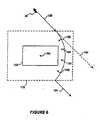
- the system 10directs the cursor 30 to a control, but does not calculate an intended position and reposition the cursor at the intended position as previously described. Instead, the system 10 adds a correction signal to the cursor control signals calculated by the CPU 12 when the cursor is in proximity with a control. As shown in Figure 6, a control 150 on the display 16 is surrounded by a predetermined control region 152. Whenever the cursor 30 is outside of the control region 152, the system 10 does not add any correction signal to the control signals.
- the system 10determines the position of the cursor relative to a center point 154 of the control 150 and generates the correction signal in the form of a correction vector 156 having X and Y coordinates that are added to the cursor control signals.
- the system 10calculates the correction vector 156 each time that the current position of the cursor 30 is determined.
- the correction vector 156causes the cursor 30 to move toward the center point 154 of the control 150 whenever the cursor is within the control region 152.
- the effect of the correction vector 156may be seen in Figure 6 where the initial direction of movement of the cursor 30 is illustrated by the arrow 158.
- the system 10does not generate any correction signal and the movement of the cursor continues in a straight line. If the system 10 did not generate correction signals, the cursor 30 would continue to move through the control region 152 in the direction indicated by the arrow 160. However, when the cursor 30 is within the control region 152, the system 10 calculates the correction vector 156 and adds it to the cursor control signals.
- the correction vector 156points toward the center point 154 of the control 150 and thus tends to cause the cursor 30 to move toward the center point 154.
- the CPU 12uses the electrical signals generated by the cursor control device 18 and the sensitivity values stored in the cursor sensitivity storage area 19 to generate the cursor control signals in the form of X and Y coordinates.
- the CPU 12adds the X and Y components of the correction vector 156 to the cursor control signals to cause the cursor 30 to move toward the center point 154 of the control 150.
- the effect of the correction vector 156may be analogized to the effect of gravity where the cursor 30 is "attracted” to the control 150.
- the control region 152is the space in which the "gravitational effect" of the control 150 is felt by the cursor 30. If the user continues to manipulate the cursor control device 18 past the control 150 so that the cursor 30 travels out of the control region 152, the cursor 30 will resume moving in the direction indicated by the arrow 164. It should be noted that the direction of movement of the cursor 30 indicate by the arrow 164 is identical to the direction of movement indicated by the arrow 158. Thus, the user can continue to move the cursor 30 on the display 16 in the desired direction, with the correction vector 156 having an effect only within the control region 152.
- cursor control devicesgenerate interrupts to the CPU 12 regardless of whether there is movement of the cursor control device, while other cursor control devices generate interrupts only when there is movement of the cursor control device by the user.
- the system 10only generates the correction vector 156 if there is movement of the cursor control device 18. If the system 10 would always adds the correction vector 156 regardless of whether or not the user manipulates the cursor control device 18, the cursor 30 would be automatically drawn to the center point 154 if the cursor is positioned within the control region 152 and not moved by the user.
- the system 10begins operation at the start 136.
- step 138the system gets the current cursor position from the current location storage area 24 (see Figure 1).
- decision 140the system 10 determines whether the cursor 30 is within the control region 152 (see Figure 6). If the cursor is not within the control region 152, the result of decision 140 is NO, and the system returns to step 138. If the current position of the cursor is within the control region 152, the result of decision 140 is YES. In that event, in step 142 the system 10 calculates the correction vector 156 (see Figure 6) which will cause the cursor 30 to move toward the center point 154 (see Figure 6).
- the magnitude of the correction vector 156may be calculated by a number of different techniques, as will be described below.
- step 44the system 10 adds the correction vector 156 to the cursor control signals.
- step 146the system 10 updates the current location storage area 24 (see Figure 1) so that the cursor 30 now has a new position on the display 16. The new position of the cursor 30 includes the contribution of the correction vector 156.
- step 146the system returns to step 138. It should be noted that the cursor position is continuously updated by the system 10 so that the cursor 30 appears to be moving acros the display 16 with a smooth motion.
- the error vector 156is calculated each time that the cursor position is updated so long as the cursor 30 is within the control region 152. Thus, the system 10 only calculates the correction vector 156 when the cursor 30 is within the control region 152.
- the correction vector 156can be calculated in a variety of manners that are well known in the art and which will not be described in detail herein.
- One such techniqueis to calculate the relative position of the cursor 30 with respect to the center point 154 and generate the correction vector 156 with a constant magnitude and a direction toward the center point 154 from the current position of the cursor.
- the gravitational attractionis inversely proportional to the square of the distance separating the two bodies.
- the magnitude of the correction vector 156correspond to the gravitational value, G, while the "mass" of the control 150 corresponds to the relative importance of the control.
- the cursor 30is designated as having a constant importance value for its "mass", while different controls on the display 16 (see Figure 1) may have different mass values depending on factors such as the relative frequency of previous selection of a control or whether the control is the default selection.
- a default selectionhas greater importance and is thus designated as having a greater mass value than other, less important controls.
- the effect of the different mass valuescauses the cursor 30 to be "attracted” to the default selection rather than some other nearby control.
- controls that have greater frequency of useare designated as having greater mass values thus causing the cursor 30 to be attracted to the controls that are selected by the user more frequently.
- the "gravitation effect" of the controlsis illustrated in Figure 8 where the cursor 30 is within the control region 152 and equidistant from the center point 154' of control 166 and the center point 154" of control 168.
- the control 168is a default value and has a designated importance value (i.e ., mass value) of three, while the control 166 has a designated importance value of one.
- the system 10calculates a correction vector 170 in a direction toward the center point 154' of the control 166 and a correction vector 172 in a direction toward the center point 154" of the control 168.
- the magnitude of the correction vector 172is three times larger than the correction vector 170 because of the higher importance value of the control 168.
- the two correction vectors 170 and 172are summed to produce the correction vector 156.
- the net effect of the two correction vectors 170 and 172 on the cursor 30is that the cursor is "attracted” or directed toward the control 168 with the higher importance value.
- the correction vectorincreases in magnitude because of the inverse distance square contribution of the distance between the cursor and the center point 154' of the control 166 in the gravitational formula.
- the importance value for a controlcan be dynamically altered when the user selects a particular control. For example, a set of controls may initially have identical importance values. However, when the user selects a particular one of the controls its importance value is increased relative to the other controls thus making it easier for the user to make the same control selection at a later time. The more often the particular one control is selected by the user, the more the cursor 30 tends to travel toward the control.
- the system 10calculates the correction vector based on the distance between the cursor 30 and the center point 154 as well as the importance values for controls 166 and 168. Thus, the magnitude of the correction vector 156 depends on the distance of the cursor 30 from the controls 166 and 168 as well as the relative importance values of the controls.
- a system for controlling the position of a cursor on a computer displaycomprises a first storage area storing position data corresponding to a first position of the cursor in a first screen display on the computer display; alteration means for altering said first screen display to generate a second screen display; a second storage area storing position data corresponding to at least a first intended position of the cursor in said second screen display; positioning means for positioning the cursor at said first intended position in said second screen display in response to the generation of said second screen display; and repositioning means for repositioning the cursor at said first position of said first screen display when the computer returns to said first screen display.
- the second storage areamay store position data which corresponds to a plurality of intended locations of the cursor in said second screen display, the system further including selection means for selecting one of said plurality of intended locations as said first intended position.
- the selection meansmay determine said one intended location by using a flag bit based on size and shape of a plurality of objects displayed on the computer display.
- the first screen displaymay be a first window having a plurality of user selectable options and the second screen display may be a second window, wherein the alteration means comprises means for opening said second window.
- the second screen displaymay also include a menu having a plurality of user selectable options, said edit means comprising means for displaying said menu, wherein one of said plurality of user selectable options corresponds to a default option, a location of said default option being selected as said first intended position in said second screen display.
- the second screen display of the system for controlling the position of a cursor on a computer displaymay also be a part of an application program, said alteration means comprising means for enabling said application program and may include a plurality of
- predefined locations on the computer displaycorresponding to a plurality of user selectable options, said first intended position in said second screen display corresponding to one of said plurality of predefined locations.
- This systemmay also include user selectable means for permitting a user to select said one predefined location as said first intended position in said second screen display and automatic selection means for automatically selecting said one predefined location as said first intended position in said second screen display.
- the automatic selection meansmay select said one predefined location as said first intended position in said second screen display based upon a previous selection, a plurality of previous selections of said one predefined location or a time-weighted average of said plurality of previous selections.
- a system for controlling the position of a cursor on a computer displaycomprises input means for entering cursor position data into the computer, prediction means for predicting an intended user destination of the cursor on the display; and positioning means for positioning the cursor at said intended user destination upon said prediction means predicting said intended user destination.
- the prediction meansmay predict said intended user destination by examining said cursor position data to determine a direction of cursor movement and determine whether said direction of cursor movement substantially coincides with a user selectable option, said user selectable option being designated as said intended user destination if said direction of cursor movement substantially coincides with said user selectable option.
- a method for controlling the position of a cursor on a computer display coupled to a computercomprising the steps of storing position data corresponding to a first position of the cursor in a first screen display on the computer display; altering said first screen display to generate a second screen display; storing position data corresponding to at least a first intended position of the cursor in said second screen display; positioning the cursor at said first intended position in said second screen display in response to the generation of said second screen display; and repositioning the cursor at said first intended position of said first screen display when the computer returns to said first screen display.
- the computermay store position data corresponding to a plurality of intended locations of the cursor in said second screen display. This method may further include the selection of one of said plurality of intended locations as said first intended position based on size and shape of a plurality of objects displayed on the computer display or using a flag bit.
- the second screen displaymay include a plurality of predefined locations on the computer display corresponding to a plurality of user selectable options, said first intended position in said second screen display corresponding to one of said plurality of predefined locations.
- This methodmay further include the steps of sensing user input to permit a user to select said one predefined location as said first intended position in said second screen display and automatically selecting said one predefined location as said first intended position in said second screen display based upon a previous selection, a plurality of previous selections of said one predefined location or a time-weighted average of said plurality of previous selections.
- a method for controlling the position of a cursor on a computer display coupled to a computercomprising the steps of entering cursor position data into the computer, predicting an intended user destination of the cursor on the display; and positioning the cursor at said intended user destination upon said prediction means predicting said intended user destination.
- the step of predictingmay comprise examining said cursor position data to determine a direction of cursor movement; and determining whether said direction of cursor movement substantially coincides with a user selectable option, said user selectable option being designated as said intended user destination if said direction of cursor movement substantially coincides with said user selectable option.
- a system for controlling the position of a cursor on a computer displaycomprises a cursor control device under control of a user to generate electrical signals corresponding to the desired movement of the cursor on the computer display; a cursor storage area storing position data corresponding to a current position of the cursor on the computer display; a cursor sensitivity storage area storing a sensitivity value corresponding to the responsiveness to the movement of the cursor control device of the cursor on the computer display, said sensitivity value having an initial sensitivity value; a control storage area storing position data corresponding to a control position on the computer display; and alteration means for altering said sensitivity value in response to said current cursor position in proximity with said control position, said alteration means decreasing said sensitivity value from said initial sensitivity value when said current position of the cursor is in proximity with said control position.
- the alteration meansmay return said sensitivity value to said initial sensitivity value when said current position of the cursor is no longer in proximity with said control position.
- a system for controlling the position of a cursor on a computer displaycomprises a cursor control device under control of a user to generate electrical signals corresponding to the desired movement of the cursor on the computer display; a cursor storage area storing position data corresponding to a current position of the cursor on the computer display; cursor position means responsive to said electrical signals for generating control signals to control the position of the cursor on the computer display; a control storage area storing position data corresponding to a control position on the computer display; and alteration means for altering said control signals in response to said current position of the cursor in proximity with said control position, said alteration means adding a position correction signal to said control signals to cause the cursor to move toward said control position.
- the cursor position meansmay generate first and second control signals corresponding to first and second orthogonal directions of movement of the cursor on the computer display, respectively, said correction signals comprising first and second orthogonal correction vectors added to said first and second control signals, respectively, to cause the cursor to move toward said control position.
- the first and second correction vectorshave a constant magnitude or a magnitude dependent on a distance between said current location of the cursor and said control position and are at a direction substantially toward said control position
- the control storage areamay store position data corresponding to first and second control positions on the computer display, said first control position having a first designated value and said second control position having a second designated value, and said alteration means adds first and second correction signals, said first and second correction signals each having a correction value corresponding to said first and second designated values, respectively.
- the cursor position meansmay generate first and second control signals corresponding to first and second orthogonal directions of movement of the cursor on the computer display, respectively, said first and second correction signals each comprising first and second orthogonal correction vectors added to said first and second control signals, respectively, to cause the cursor to move toward one of said first and second control positions having a greater designated value.
- the first and second correction vectorsmay have a magnitude dependent on said first and second designated values, respectively, or each may have a magnitude dependent on a distance between said current location of the cursor and said first and second control positions, and a direction toward said one of said first and second control positions with a greater importance value.
- the system for controlling the position of a cursor on a computer displaymay further include value alteration means for altering said first and second designated values wherein said value alteration means alters said first designated value based on a previous selection of said first control position.
Landscapes
- Engineering & Computer Science (AREA)
- General Engineering & Computer Science (AREA)
- Theoretical Computer Science (AREA)
- Human Computer Interaction (AREA)
- Physics & Mathematics (AREA)
- General Physics & Mathematics (AREA)
- User Interface Of Digital Computer (AREA)
- Controls And Circuits For Display Device (AREA)
- Digital Computer Display Output (AREA)
Description
- The invention relates generally to a system and method for controlof a cursor on a computer display screen.
- Computers have become common in the work place and at home.Early computer systems required extensive knowledge of computer programmingto effectively operate the computer. Newer computers have been designed topermit simplified use by those without formal background in computer science.Operating systems, such as the Microsoft® Windows™ operating systemprovide a graphical environment that can be used by persons with little or noprevious experience in the use of computers. Thus, computers have becomeeasier to operate and their use has become more pervasive.
- As computers become even more common, it is important that thecomputer must become even easier to operate for the person using the computer.For example, the use of a cursor pointing device, such as a mouse, trackball, orthe like, permits the easy manipulation of a cursor on the visual display coupledto the computer. However, there are situations in which even the movement ofthe cursor with a mouse becomes inefficient. Therefore, it can be appreciatedthat there is a great need for a system and method for controlling the positioningof a cursor on the computer display that simplifies the positioning of the cursoron the visual display.
- U.S. 4,987,411 discloses a pointing apparatus where the presence/absence of an object to bedesignated by a cursor is confirmed to be on or near a position along the moving direction,and the cursor is jumped and moved to the object position. A memory stores an iconregistration table, and there is provided an icon position determination circuit. A memorystores an icon registration table, and there is provided an icon position determination circuit.Cursor current position information is stored. The direction in which the cursor is to bejumped is determined in correspondence with the current position and the moving direction ofthe cursor. The cursor is caused to jump from a position to the position of an icon. For doingso, co-ordinates near the icon are calculated by using the moving direction data. Themovement is done instantaneously. The cursor is jumped even if the cursor is far away fromthe target icon, and when the icon is based apart from the cursor.
- It is the object of the invention to provide an improved cursor control system and method.
- This object is solved by the invention as claimed in the independent claims.
- Preferred embodiments are defined by the dependent claims.
- The present invention is embodied in a system that control theposition of the cursor on a computer display. A first storage area stores theposition data corresponding to a first position of the cursor and a first screendisplay on the computer display. An alteration means alters the first screendisplay in some manner to generate a second screen display. The second screendisplay may be generated with the result of opening a computer window,enabling an application program, or selecting a menu item. A second storagearea stores the position data corresponding to at least the first intended positionof the cursor in the second screen display. Positioning means position the cursor at the first location in the second screen display in response to the generation ofthe second screen display.
- In one embodiment the second storage area stores position datacorresponding to a plurality of intended positions of the cursor in the secondscreen display. The system further includes selection means for selecting one ofthe plurality of the intended positions as the first location in the second screendisplay. The selection means may use a flag-bit to select the intended location.Alternatively, the selection means may determine the intended location based onthe size and shape of a plurality of objects displayed on the computer display.
- The system may further include repositioning means to repositionthe cursor at the first position of the first screen display when the computerreturns to the first screen display.
- The second screen display may include a plurality of predefinedlocations on the computer display corresponding to a plurality of user selectableoptions, with the first position in the second screen display corresponding to oneof the plurality of predefined locations. The system may further include userselectable means for permitting the user to select one predefined location as thefirst position in the second screen display. Alternatively, the system may includeautomatic selection means for automatically selecting one of the predefinedlocations as the first position in the second screen display. The automaticselection may be based on the previous selection of the predefined location.Alternatively, the automatic selection means may select the predefined locationbased on a plurality of previous selections of the one predefined location. Theplurality of previous selections may be given a time-weighted average todetermine the predefined location to be designated as the first position in thesecond screen display.
- In an alternative embodiment, a system for controlling the positionof a cursor on a computer display comprises input means for entering cursorposition data into the computer, prediction means for predicting an intended userdestination of the cursor on the display, and a positioning means for positioningthe cursor at the intended user destination upon the prediction means predictingthe intended user destination. The prediction means predicts the intended userdestination by examining cursor position data to determine a direction of cursormovement and determines whether the direction of cursor movementsubstantially coincides with a user selectable option, with the user selectableoption being designated as the intended user destination if the direction of cursormovement substantially coincides with the user selectable option.
- In another alternative embodiment, the system alters the sensitivityof the cursor control device when the cursor is in proximity with a control so thatthe cursor moves less distance for a given unit of movement of the cursor controldevice than when the cursor is not in proximity with a control. Thisadvantageously permits the user to more easily position the cursor on the control.
- In yet another embodiment, the system determines a correctionsignal that moves the cursor toward the control when the cursor is in proximitywith a control. The correction signal may take the form of a vector added to thecursor control signals. The magnitude of the correction vector may be constant,or dependent on the distance between the position of the control and the cursoron the display. In an alternative embodiment, the magnitude of the correctionsignal is dependent of the relative importance of controls. Controls aredesignated as having a relative importance value. The correction signals tend tomove the cursor towards controls with a relatively higher importance value.
- Figure 1 is a functional block diagram of a system according to thepresent invention.
- Figure 2A is a flow chart of the operation of the system of Figure 1when opening a new window.
- Figure 2B is a flow chart of the operation of the system of Figure 1when closing a window.
- Figures 3A through 3D are sample screen displays illustrating theoperation of the system of Figure 1.
- Figure 4 is a flow chart of the operation of the system of Figure 1when predicting an intended user location in an unaltered screen display.
- Figure 5 is a flow chart of the operation of the system of Figure 1when positioning the cursor in proximity with a control.
- Figure 6 is a sample screen display enlarged to illustrate theoperation of the system of Figure 1 to generate correction signals to position thecursor on a control.
- Figure 7 is a flow chart of the operation of the system of Figure 1when calculating correction signals to position the cursor on a control.
- Figure 8 is a sample screen display enlarged to illustrate theoperation of the system of Figure 1 to generate variable magnitude correctionsignals to position the cursor on a control.
- The present invention allows a user to enter commands into acomputer with less physical movement of the mouse than is required by systemsof the prior art. While the following discussion relates to a mouse, it can readilybe appreciated that the principles of the present invention are equally applicableto other cursor pointing devices, such as a trackball, joystick, and keyboard. Theinvention may be easily incorporated into any computer from a personalcomputer to a mainframe computer.
- The present invention automatically positions a cursor atpredetermined locations on a computer visual display in response to usercommands. In a graphical environment such as the Windows™ operatingsystem, the present invention can position the cursor in a new predeterminedlocation on the computer display each time that a window is opened or closed.When a new window is opened, or a menu displayed on the computer display,the present invention determines a new location for the cursor and automaticallypositions the cursor at that location. When the window is closed or the menuselection made by the user, the present invention returns the cursor to thelocation prior to opening the new window or selecting the menu. The presentinvention is not limited to a windows environment, but can also operate oncomputer systems that do not display graphical windows on the computerdisplay. Any change in the computer display, whether caused by opening awindow, closing a window, displaying a menu or the like can be considered analteration in the computer display and is intended to be encompassed by thepresent invention.
- The present invention is embodied in a
system 10 shown in theblock diagram of Figure 1. A central processing unit (CPU) 12 performs theanalysis functions that will be described below. TheCPU 12 can be any of anumber of well known devices. Thesystem 10 includes amemory 14, whichmay comprise both random access memory (RAM) and read-only memory(ROM). A computervisual display 16, such as an LED or CRT display, is alsoincluded in thesystem 10. Thedisplay 16 typically comprises an array of pixelsarranged in two orthogonal dimensions to form a two dimensional display, withX and Y coordinates used to indicate the location of each pixel in the array. Thedisplay 16 may be an integral part of thesystem 10, such as when the system isincorporated into a laptop computer, or may be a stand alone device. - The
system 10 also includes acursor control device 18 thatcontrols the position of a cursor generated on thedisplay 16. Thecursor controldevice 18 may be a mouse, joystick, trackball, keyboard, or the like. The presentinvention is not limited by the specific form of thecursor control device 18. Thecursor control device 18 generates electrical signals indicative of the desiredmovement of the cursor. TheCPU 12 interprets the electrical signals from thecursor control device 18 and alters the current location storage area 24accordingly. If thecursor control device 18 is a mouse, trackball, or the like,there are generally two electrical signals corresponding to the movement of thecursor control device 18 in two orthogonal dimensions corresponding to the twodimensions on thedisplay 16. The electrical signals from thecursor controldevice 18 are converted by theCPU 12 into cursor control signals correspondingto X and Y coordinates on thedisplay 16. - The
system 10 also includes a cursorsensitivity storage area 19that contains sensitivity values relating the amount of movement of thecursorcontrol device 18 to the amount of movement of the cursor on thedisplay 16.Typically, the user selects the sensitivity value for both orthogonal dimensions(i.e., the X and Y dimensions) of movement of thecursor control device 18. TheCPU 12 uses both the electrical signals from thecursor control device 18 and thesensitivity values in the cursorsensitivity storage area 19 to determine the valueof the cursor control signals. A relatively high sensitivity value will result ingreater movement of the cursor for a given unit of movement of thecursorcontrol device 18 than will a lower sensitivity value. Typically, the user selectsthe sensitivity value for both orthogonal dimensions (i.e., the X and Ydimensions). - The
system 10 also includes a command entry device 20, whichmay be a button on thecursor control device 18 or on a keyboard (not shown).Thesystem 10 may also include a secondcommand entry device 21, such as asecond button on thecursor control device 18 or on the keyboard (not shown).The user can position the cursor at a desired location on thedisplay 16 and pressthe command entry device 20 to activate a computer command associated withthe selected location on the display. The various components of thesystem 10are coupled together by abus 22, which may carry power as well as data signals. - A current location storage area 24 of the
system 10 contains thecursor control signals (i.e., X and Y coordinates) corresponding to the currentlocation of the cursor on thedisplay 16. The current location storage area 24may be part of thememory 14. If the contents of thedisplay 16 are altered, thesystem 10 determines a new location for the cursor relative to the altered displayand stores the new location in the current location storage area 24. Prior todetermining the new location of the cursor and updating the current locationstorage area 24, thesystem 10 stores the current location of the cursor in areturnlocation storage area 26 to permit thesystem 10 to return the cursor to theprevious location when the contents of thedisplay 16 are returned to its previousstate. The returnlocation storage area 26 may also be part of thememory 14.For example, thesystem 10 may be used with an operating system such as theWindows™ operating system. When a new window, such as a dialog boxwindow, is opened, thesystem 10 saves the current location of the cursor in thereturnlocation storage area 26 and returns the cursor to its previous locationwhen the new window is closed and the previous window is reopened. In agraphical environment such as the Windows™ operating system, the previouswindow automatically reopens when the new window is closed. If yet anothernew window is opened, the system saves a return location for each window thathas been opened in the returnlocation storage area 26. Each window will have areturn location and identification (window ID) associated with it to permit thereturn of the cursor to the previous location when the associated window isdeactivated. Thus, the user can select options from a plurality of windowswithout ever having to manually change the location of the cursor on thedisplay 16 by moving the mouse or manipulating the trackball. - The
system 10 has a controllist storage area 28, which stores a listof possible cursor locations for the new screen display. The contents of thecontrollist storage area 28 corresponds to a list of user selectable options, whichmay vary from one application to another. For example, the controllist storagearea 28 may contain a list corresponding to locations of user selectable optionssuch as control button icons or menu items displayed on thedisplay 16. For thesake of convenience, the user selectable options will be referred to herein ascontrols to indicate that they perform some control function in the softwarerunning on the computer. The controls are defined by the specific application ina well known manner that will not be described herein. Generally, one of thecontrols in the controllist storage area 28 will correspond to a predetermineddefault selection for the particular application. In an operating system such asthe Windows™ operating system, the default selection is indicated by a flag databit, which is also stored in the controllist storage area 28. Thesystem 10 stepsthrough the controllist storage area 28 to determine if there is a default selectionof one of the controls for the new screen display. If a default selection is found by thesystem 10, the system positions the cursor at the location on thedisplay 16 corresponding to the default selection. It should be noted that in agraphical environment, such as the Windows™ operating system, the position ofthe control is fixed relative to the corresponding window. If the window itself isrepositioned on thedisplay 16, the location of the control on the display will alsochange to maintain the fixed position relationship to the window. If no defaultselection is found, thesystem 10 will not reposition the cursor when the newscreen display is displayed. If the new screen display is part of an applicationprogram, thesystem 10 will examine the new screen display to determine if anyobjects in the new screen display correspond to controls. Thesystem 10analyzes the size and shape of objects in the new screen display to determine ifany objects correspond to controls. Alternatively, application programs writtenfor a graphical environment, such as the Windows™ operating system, mayindicate the default selection using a flag data bit, as described above. It shouldbe noted that the controls may be button icons, menu items, or the like.Alternatively, the user can select a default location such as a cell in a databaseapplication program. Thesystem 10 improves the efficiency of operation andenhances the functionality of cursor movement by positioning the cursor at alocation that permits the user to perform additional functions without additionalmanipulation of thecursor control device 18. The present invention is notlimited by the specific form in which the controls are displayed. - The
system 10 permits the user to manually select the defaultselection for a screen display. The selection of a new default selection can beaccomplished by a number of well known techniques. One such example is thedisplay of a dialog box asking the user if user wishes to make the currentselection the default selection. Another example is the use of a second commandentry device (not shown), such as a second button on thecursor controldevice 18, a button on the keyboard (not shown), or the like, to indicate to thesystem 10 that the user is selecting a different selection as the default selection.The new default selection can be marked with the flag data bit, as describedabove. - The
system 10 includes a mechanism for the automaticdetermination of a default selection based on previous usage. This dynamicadaptive process is particularly useful in situations where the user is less familiarwith computer operations and cannot manually change the default selectioneasily. For example, in one mode of operation, thesystem 10 designates thepreviously used selection for a particular screen display as the default selection the next time that the particular screen display is shown on thedisplay 16. Theautomatic selection of the default selection can also be based on other forms ofprevious usage, such as an average of several previous selections or a time-weightedaverage of several previous selections for a particular screen display.More recent selections from among the plurality of selections are given greaterweight when calculating a time-weighted average. Those skilled in the art willappreciate that other techniques could be used for determining the most likelyuser selection from among the plurality of controls. Such techniques areintended to be encompassed by the present invention. Thesystem 10 positionsthe cursor at the default selection, whether the default selection is manuallyselected by the user, automatically selected by the system, or by somecombination of user selection and automatic selection. - The operation of the
system 10 may be best illustrated in the flowchart of Figure 2A, taken in conjunction with the sample screen displays ofFigures 3A to 3D. Thesystem 10 may be activated by a user command or byauto loading the software that operates the system whenever the user beginsoperation on the computer. At thestart 50, shown in Figure 2A, thedisplay 16has afirst window 29 activated. Thedisplay 16 includes acursor 30, shown inFigure 3A as an arrow, and may also include one or more controls, such as aFILE button 32. The user selects a function associated with theFILE button 32,by positioning thecursor 30 over theFILE button 32 and depressing thecommand entry device 20 (see Figure 1). In response to the selection of theFILE button 32, thesystem 10 stores the current location of thecursor 30 in thereturnlocation storage area 26 instep 52. As previously discussed, thesystem 10 uses the data stored in the returnlocation storage area 26 to repositionthecursor 30 at its original location after the user selects a control or a newlyactivated window is deactivated - In step 54, the
system 10 alters the screen display on thedisplay 16in response to the user selection or activation of a new window. This altereddisplay is shown in Figure 3B where a plurality of controls associated with theFILE button 32 are displayed. The controls are predefined by the particularsoftware program running on the computer and can vary from one window to thenext. In the example of Figure 3B, the controls include aNEW button 34, whichis used to create a new file, anOPEN button 36, which is used to open anexisting file, and aCLOSE button 38, which is used to close an open file. Instep 56, the various controls are loaded in the control list 28 (see Figure 1) whenthe contents of thedisplay 16 are altered. The locations of the controls on thedisplay 16 are also predefined by the particular software program running on thecomputer. In the example of Figure 3B, theNEW button 34 is the defaultselection. - The
system 10 sequentially analyzes the controls in the controllist 28 (see Figure 1) to select a location at which thecursor 30 will bepositioned. Indecision 58, thesystem 10 determines if the control beinganalyzed matches a desired style. The term "desired style" refers to the specificfeatures that the controls may have. As previously discussed, the type ofcontrols in thecontrol list 28 may vary from one computer operating system toanother. The process of matching the controls to the desired style depends onthe particular operating system and on other factors, such as whether the newscreen display is a new window, a menu, or an application program. Forexample, certain software such as the Windows™ operating system, has a flagdata bit associated with the default selection, as previously discussed. Thesystem 10 uses the data flag bit to identify the default selection. In this example,the data flag bit identifies the control with the desired style. In an applicationprogram, thedisplay 10 may not have a data flag bit to identify the defaultselection. In such situations, thesystem 10 analyzes the data on thedisplay 16and attempts to identify patterns such as a button, menu item, or other control.In this example, the desired style is a pattern on thedisplay 16 that appears like abutton, menu item, or other control. - If the control being analyzed does not match the desired style, theresult of
decision 58 is NO. In that event, thesystem 10, indecision 60,determines if the control being analyzed in thecontrol list 28 is the last controlin the list. If the control in thecontrol list 28 is the last control, the result ofdecision 60 is YES, and thesystem 10 ends the process in step 62 withoutrepositioning the cursor 30 (see Figure 3B). If the control being analyzed is notthe last control in thecontrol list 28, the result ofdecision 60 is NO, and instep 64, thesystem 10 gets the next control from the control list 28 (see Figure 1)and returns todecision 58. - If the control being analyzed does match the desired style, theresult of
decision 58 is YES. In that event, thesystem 10 gets location data forthe selected control in step 66. The location data for each control is provided tothe operating system by the individual application programs. This information isstored in the memory 14 (see Figure 1) and can be retrieved by thesystem 10. Instep 68, the system positions the cursor 30 (see Figure 3B) at the center of theselected control location on thedisplay 16. In the example, of Figure 3B, thesystem 10 positions thecursor 30 at the center of theNEW button 34. Thesystem 10 ends the process of positioning thecursor 30 instep 70. Thus, thecursor 30 is automatically positioned at the default location whenever the useropens a new window. In Figure 3B, the user selects theFILE button 32, and thesystem 10 automatically positions thecursor 30 at theNEW button 34. Thus,thesystem 10 eliminates the time required to manually reposition the cursor andmay reduce the fatigue experienced by the operator when manually repositioningthe cursor. - The user may next select the
NEW button 34 in Figure 3B bysimply pressing the command entry device 20 (see Figure 1). If the user wishesto select a control other than theNEW button 34, the user manually positions thecursor 30 to another selection, such as theCLOSE button 38, as shown inFigure 3C. If the user selects theCLOSE button 38, thesystem 10 will followthe procedure discussed above when displaying adialog box 40, such as shownin Figure 3D. Thedialog box 40, which is essentially a new window, displays amessage to the user asking if the user wishes to save the contents of the file. Inaddition, thedialog box 40 contains aYES button 42, which causes the computerto save the contents of the file before closing the file. A NObutton 44 causesthe computer to close the file without saving it, and a CANCELbutton 46cancels the selection of closing of the file. In the example of Figure 3D, theYES button 42 is the default selection because the user generally wants to saveany changes to the open file. When thedialog box 40 is opened, thesystem 10positions thecursor 30 at the center of theYES button 42. The user may nextselect the default selection by simply pressing the command entry device 20 (seeFigure 1) if the user wishes to select theYES button 42. If not, the user maymove thecursor 30 using thecursor control device 18 to another control andselect that control by pressing the command entry device 20. - As previously discussed, the
system 10 repositions thecursor 30 atits previous location when a new window is closed or a menu item is selected.When the user selected theCLOSE button 38 in Figure 3C, the software runningon the computer altered thedisplay 16 to delete theNEW button 34, theOPENbutton 36, and theCLOSE button 38. However, thesystem 10 will not returnthecursor 30 to the previous location shown in Figure 3A (i.e., the FILEbutton 32) because selection of theCLOSE button 38 caused the display 16 (seeFigure 1) to display another new window (i.e., the dialog box 40), as shown inFigure 3D. Thus, thedisplay 16 has not returned to the display shown inFigure 3A, and thecursor 30 will not be repositioned at theFILE button 32. - However, when the user makes a selection from one of the
YESbutton 42, theNO button 44 or the CANCELbutton 46 in Figure 3D, thecomputer will close thedialog box 40, which returns thedisplay 16 to thedisplay shown in Figure 3A with thecursor 30 being repositioned over theFILEbutton 32. This occurs because thesystem 10 uses the data stored in the returnlocation storage area 26 (see Figure 1) to reposition thecursor 30 to the locationthat it was at when thedisplay 16 had the appearance shown in Figure 3A. - The operation of the
system 10 when closing a window isillustrated in the flowchart of Figure 2B. Thesystem 10 starts atstep 78 with thedeactivation of the current window (e.g., thedialog box 40 in Figure 3D). Thedeactivation may occur automatically as a result of the user selecting an option,such as selecting theYES button 42 in Figure 3D, or may occur as the result ofthe user manually closing a window in a manner well known to those skilled inthe art. - In
decision 80, the system compares the window ID for the currentwindow with the list of stored window IDs. to determine if the current windowID is on the list of stored window IDs. As previously discussed, the window IDand return location are stored in the return location storage area 26 (seeFigure 1). If the window ID is not on the list of stored window IDs, the result ofdecision 80 is NO. In that event, thesystem 10 ends the process of deactivatingthe window instep 82, and does not reposition thecursor 30. If the window IDis on the list of stored window IDs, the result ofdecision 80 is YES. In thatevent, thesystem 10 positions thecursor 30 to the return location associated withthe particular window ID in step 84. Instep 86, thesystem 100 removes thewindow ID and return location from the return location storage area 26 (seeFigure 1). Thesystem 10 ends the process of closing a window instep 88. - The
system 10 allows the user to rapidly select several optionswithout ever having to manually reposition the cursor. While the aboveexamples of thesystem 10 relate to a series of windows on thedisplay 16, thoseof ordinary skill in the art will readily appreciate that the present invention is notlimited to a situation in which the computer displays data in the form ofwindows. - The above examples illustrate the use of the
system 10 toreposition the cursor whenever thedisplay 16 is altered, whether by opening anew window, selecting a menu option, or the like. Thesystem 10 can alsoreposition the cursor to a predetermined location on thedisplay 16 even thoughthe display has not been altered. As described in greater detail below, the system analyzes the cursor movement when the user is operating thecursor controldevice 18 and predicts the intended predetermined location based on the cursormovement. When thesystem 10 predicts the intended location, it automaticallyrepositions the cursor at the predicted intended location. For example, if the useris moving the cursor toward theFILE button 32, shown in Figure 3A, thesystem 10 can automatically reposition thecursor 30 at the location of theFILEbutton 32 on thedisplay 16 thus saving the user the time required to actuallyreposition the cursor at the intended location manually. This is particularlyuseful in situations where the current location of thecursor 30 on thedisplay 16is a long distance from the intended location, which may require the user tomanually manipulate the cursor control device 18 (see Figure 1) extensively toreposition the cursor at the desired location. - The
system 10 includes an enabling mechanism that enables thesystem to predict the intended location when thedisplay 16 has not been altered.The selective enabling of this aspect of the invention prevents thesystem 10from inadvertently repositioning the cursor to a predicted intended location whenthe user is simply moving the cursor to some location other than one of thepredetermined locations on thedisplay 16. The enabling mechanism may be amenu selection that enables the prediction of the intended location, or the secondcommand entry device 21 (see Figure 1). When the secondcommand entrydevice 21 is used, the user depresses the secondcommand entry device 21 toenable the automatic prediction of the intended location while manipulating thecursor control device 18. Thesystem 10 then automatically predicts the intendedlocation of the cursor and repositions the cursor at the predicted intendedlocation. When the user is not depressing the secondcommand entry device 21,thesystem 10 does not predict the intended location. The automatic positioningof thecursor 30 when thedisplay 16 is altered is not affected by the enablingmechanism described above. - Alternatively, the
system 10 can be designed to always predict anintended location, and the secondcommand entry device 21 used to instruct thesystem 10 to reposition the cursor at the predicted intended location. In thismanner, thesystem 10 always calculates the predicted intended location, but willnot reposition the cursor at the predicted intended location unless the automaticrepositioning feature is enabled. - The operation of the prediction feature of the
system 10 isillustrated in the flowchart of Figure 4. Instep 100, the user enables theprediction feature in a manner described above. Instep 102, the system stores the current cursor position, which may be stored in the memory 14 (seeFigure 1). Instep 104, the system waits for the next cursor control device event,such as an interrupt. Instep 106, thesystem 10 gets the current cursor position.Instep 108, thesystem 10 compares the current cursor position with the storedcursor position. Instep 110, thesystem 10 determines the direction of cursormovement based on the current cursor position and a stored cursor position. Indecision 112, the system determines whether there is a control in the direction ofcursor movement. In the presently preferred embodiment, thesystem 10 scansthrough a predetermined angle (e.g., plus or minus 5°) from the current cursorposition along the direction of cursor movement. The scan angle can be selectedby the user depending on the type of screen display. The present invention is notlimited by the particular scan angle. If there is no control within the scannedarea, the result ofdecision 112 is NO, and the system returns to step 102 andrepeats the operation described above. If there is a control within the scannedarea, the result ofdecision 112 is YES. In that event, the control that falls withinthe scanned area is designated as the predicted intended location. If more thanone control is present within the scanned area, thesystem 10 designates thecontrol closest to the actual direction of cursor movement as the predictedintended location. Instep 114, thesystem 10 positions the cursor at the center ofthe predicted intended location. Followingstep 114, the system returns tostep 102 and continues the process described above. - The
system 10 also can dynamically alter the cursor control signalsused to position thecursor 30 on thedisplay 16 in order to simplify the processof positioning the cursor on a control. In one embodiment, thesystem 10dynamically alters the sensitivity values stored in the cursor sensitivity storagearea 19 (see Figure 1) when thecursor 30 is positioned over a control on thedisplay 16. As previously described, the user can adjust the sensitivity value sothat one unit of movement of thecursor control device 18 corresponds to aselected number of units of movement of thecursor 30 on thedisplay 16. Thegreater the sensitivity values, the greater the movement of thecursor 30 for agiven amount of manipulation of thecursor control device 18. TheCPU 12responds to both the electrical signals generated by thecursor control device 18and the sensitivity values to determine data values, or cursor control signals, forthecursor 30 and alters the current location storage area 24 accordingly. Innormal operation, the sensitivity values have been predetermined or selected bythe user, and are stored in the cursor sensitivity storage area 19 (see Figure 1). - When the
cursor 30 is in proximity with a control, thesystem 10decreases the sensitivity values by a factor of ten so that one unit of movementof thecursor control device 18 will result in only one tenth of the movement ofthecursor 30 than previously obtained. Thecursor 30 in effect slows downwhen passing in proximity with a control. The position of the controls areobtained from the control list 28 (see Figure 1). In the currently preferredembodiment, the sensitivity values are altered only when thecursor 30 isactually over the position of the control on thedisplay 16. As can readily beappreciated, the region in which the sensitivity values are altered, and theamount of change in the sensitivity values are not limited to the particularexample presented above. - The operation of the
system 10 in this embodiment is illustrated inthe flowchart of Figure 5. Thesystem 10 begins operation at thestart 120. Instep 122, thesystem 10 gets the current cursor position, which is stored in thecurrent location storage area 24 (see Figure 1). Indecision 124, the systemdetermines whether the current position of the cursor coincides with the positionof a control on thedisplay 16. If the current cursor position does not correspondto the position of a control on thedisplay 16, the result ofdecision 124 is NOand the system returns to step 122. If the current cursor position doescorrespond to the position of a control on thedisplay 16, the result ofdecision 124 is YES. In that event, thesystem 10 decreases the cursor sensitivityvalues instep 126. As previously described, the cursor sensitivity values arestored in the cursor sensitivity storage area 19 (see Figure 1). - In
step 128, thesystem 10 gets the current cursor position from thecurrent location storage area 24. Indecision 130, thesystem 10 determineswhether the current position of the cursor still coincides with the position of acontrol on thedisplay 16. If the current cursor position does coincide with theposition of a control on thedisplay 16, the result ofdecision 130 is YES. In thatevent, the system returns to step 128 and maintains the sensitivity values at thedecreased level. If the current position of the cursor no longer coincides with theposition of a control on thedisplay 16, the result ofdecision 130 is NO. In thatevent, thesystem 10 returns the cursor sensitivity values to their initial values instep 132. Thesystem 10 ends the process instep 134. Thus, the cursor appearsto slow down whenever its position on thedisplay 16 coincides with the positionof a control. This techniques simplifies the process of positioning thecursor 30on a control. This is especially useful for new users who may not be familiarwith operation of thecursor control device 18 or with small children who may not have the motor skills to quickly and accurately position the cursor on a smallcontrol on thedisplay 16. - In another alternative embodiment, the
system 10 directs thecursor 30 to a control, but does not calculate an intended position and repositionthe cursor at the intended position as previously described. Instead, thesystem 10 adds a correction signal to the cursor control signals calculated by theCPU 12 when the cursor is in proximity with a control. As shown in Figure 6, acontrol 150 on thedisplay 16 is surrounded by apredetermined controlregion 152. Whenever thecursor 30 is outside of thecontrol region 152, thesystem 10 does not add any correction signal to the control signals. However,when thecursor 30 is within thecontrol region 152, thesystem 10 determinesthe position of the cursor relative to acenter point 154 of thecontrol 150 andgenerates the correction signal in the form of acorrection vector 156 having Xand Y coordinates that are added to the cursor control signals. Thesystem 10calculates thecorrection vector 156 each time that the current position of thecursor 30 is determined. Thecorrection vector 156 causes thecursor 30 to movetoward thecenter point 154 of thecontrol 150 whenever the cursor is within thecontrol region 152. - The effect of the
correction vector 156 may be seen in Figure 6where the initial direction of movement of thecursor 30 is illustrated by thearrow 158. When thecursor 30 is outside thecontrol region 152, thesystem 10does not generate any correction signal and the movement of the cursorcontinues in a straight line. If thesystem 10 did not generate correction signals,thecursor 30 would continue to move through thecontrol region 152 in thedirection indicated by thearrow 160. However, when thecursor 30 is within thecontrol region 152, thesystem 10 calculates thecorrection vector 156 and adds itto the cursor control signals. Thecorrection vector 156 points toward thecenterpoint 154 of thecontrol 150 and thus tends to cause thecursor 30 to movetoward thecenter point 154. As previously described, the CPU 12 (see Figure 1)uses the electrical signals generated by thecursor control device 18 and thesensitivity values stored in the cursorsensitivity storage area 19 to generate thecursor control signals in the form of X and Y coordinates. TheCPU 12 adds theX and Y components of thecorrection vector 156 to the cursor control signals tocause thecursor 30 to move toward thecenter point 154 of thecontrol 150. - The effect of the
correction vector 156 may be analogized to theeffect of gravity where thecursor 30 is "attracted" to thecontrol 150. In thisanalogy, thecontrol region 152 is the space in which the "gravitational effect" of thecontrol 150 is felt by thecursor 30. If the user continues to manipulate thecursor control device 18 past thecontrol 150 so that thecursor 30 travels out ofthecontrol region 152, thecursor 30 will resume moving in the directionindicated by thearrow 164. It should be noted that the direction of movement ofthecursor 30 indicate by thearrow 164 is identical to the direction of movementindicated by thearrow 158. Thus, the user can continue to move thecursor 30on thedisplay 16 in the desired direction, with thecorrection vector 156 havingan effect only within thecontrol region 152. - It should be noted that some cursor control devices generateinterrupts to the
CPU 12 regardless of whether there is movement of the cursorcontrol device, while other cursor control devices generate interrupts only whenthere is movement of the cursor control device by the user. In the presentlypreferred embodiment, thesystem 10 only generates thecorrection vector 156 ifthere is movement of thecursor control device 18. If thesystem 10 wouldalways adds thecorrection vector 156 regardless of whether or not the usermanipulates thecursor control device 18, thecursor 30 would be automaticallydrawn to thecenter point 154 if the cursor is positioned within thecontrolregion 152 and not moved by the user. - The use of the
correction vector 156 by thesystem 10 is describedin the flowchart of Figure 7. Thesystem 10 begins operation at thestart 136. Instep 138, the system gets the current cursor position from the current locationstorage area 24 (see Figure 1). Indecision 140, thesystem 10 determineswhether thecursor 30 is within the control region 152 (see Figure 6). If thecursor is not within thecontrol region 152, the result ofdecision 140 is NO, andthe system returns to step 138. If the current position of the cursor is within thecontrol region 152, the result ofdecision 140 is YES. In that event, instep 142thesystem 10 calculates the correction vector 156 (see Figure 6) which willcause thecursor 30 to move toward the center point 154 (see Figure 6). Themagnitude of thecorrection vector 156 may be calculated by a number ofdifferent techniques, as will be described below. - In
step 44, thesystem 10 adds thecorrection vector 156 to thecursor control signals. Instep 146, thesystem 10 updates the current locationstorage area 24 (see Figure 1) so that thecursor 30 now has a new position onthedisplay 16. The new position of thecursor 30 includes the contribution ofthecorrection vector 156. Followingstep 146 the system returns to step 138. Itshould be noted that the cursor position is continuously updated by thesystem 10 so that thecursor 30 appears to be moving acros thedisplay 16 with a smooth motion. Theerror vector 156 is calculated each time that the cursor position isupdated so long as thecursor 30 is within thecontrol region 152. Thus, thesystem 10 only calculates thecorrection vector 156 when thecursor 30 is withinthecontrol region 152. - The
correction vector 156 can be calculated in a variety of mannersthat are well known in the art and which will not be described in detail herein.One such technique is to calculate the relative position of thecursor 30 withrespect to thecenter point 154 and generate thecorrection vector 156 with aconstant magnitude and a direction toward thecenter point 154 from the currentposition of the cursor. Alternatively, the system may actually use the formulafor gravitational attraction between two bodies, which is defined by thefollowing:correction vector 156correspond to the gravitational value, G, while the "mass" of thecontrol 150corresponds to the relative importance of the control. - In this embodiment, the
cursor 30 is designated as having aconstant importance value for its "mass", while different controls on thedisplay 16 (see Figure 1) may have different mass values depending on factorssuch as the relative frequency of previous selection of a control or whether thecontrol is the default selection. A default selection has greater importance and isthus designated as having a greater mass value than other, less importantcontrols. The effect of the different mass values causes thecursor 30 to be"attracted" to the default selection rather than some other nearby control.Similarly, controls that have greater frequency of use are designated as havinggreater mass values thus causing thecursor 30 to be attracted to the controls thatare selected by the user more frequently. - The "gravitation effect" of the controls is illustrated in Figure 8where the
cursor 30 is within thecontrol region 152 and equidistant from thecenter point 154' ofcontrol 166 and thecenter point 154" ofcontrol 168. In theexample of Figure 8, thecontrol 168 is a default value and has a designatedimportance value (i.e., mass value) of three, while thecontrol 166 has a designated importance value of one. Thesystem 10 calculates acorrectionvector 170 in a direction toward the center point 154' of thecontrol 166 and acorrection vector 172 in a direction toward thecenter point 154" of thecontrol 168. The magnitude of thecorrection vector 172 is three times largerthan thecorrection vector 170 because of the higher importance value of thecontrol 168. The twocorrection vectors correction vector 156. The net effect of the twocorrection vectors cursor 30 is that the cursor is "attracted" or directed toward thecontrol 168 with the higher importance value. As thecursor 30 is moved closerto thecontrol 168, the correction vector increases in magnitude because of theinverse distance square contribution of the distance between the cursor and thecenter point 154' of thecontrol 166 in the gravitational formula. - The importance value for a control can be dynamically alteredwhen the user selects a particular control. For example, a set of controls mayinitially have identical importance values. However, when the user selects aparticular one of the controls its importance value is increased relative to theother controls thus making it easier for the user to make the same controlselection at a later time. The more often the particular one control is selected bythe user, the more the
cursor 30 tends to travel toward the control. Thesystem 10 calculates the correction vector based on the distance between thecursor 30 and thecenter point 154 as well as the importance values forcontrols correction vector 156 dependson the distance of thecursor 30 from thecontrols - As is apparent to those skilled in the art, other formulae could beused to determine the magnitude of the correction vector based on the relativeimportance of various controls on the
display 16. It should be noted that thedisplay 16 in the examples presented above display data in a two-dimensionalformat. However, the principles of the present invention are equally applicableto adisplay 16 which can display data in a three dimensional format. - It is to be understood that even though various embodiments andadvantages of the present invention have been set forth in the foregoingdescription, the above disclosure is illustrative only, and changes may be madein detail, yet remain within the broad principles of the invention. Therefore, thepresent invention is to be limited only by the appended claims.
- According to an aspect of the present invention a system for controlling the positionof a cursor on a computer display comprises a first storage area storing position datacorresponding to a first position of the cursor in a first screen display on the computerdisplay; alteration means for altering said first screen display to generate a secondscreen display; a second storage area storing position data corresponding to at least afirst intended position of the cursor in said second screen display; positioning means forpositioning the cursor at said first intended position in said second screen display inresponse to the generation of said second screen display; and repositioning means forrepositioning the cursor at said first position of said first screen display when thecomputer returns to said first screen display.
- The second storage area may store position data which corresponds to a pluralityof intended locations of the cursor in said second screen display, the system furtherincluding selection means for selecting one of said plurality of intended locations as saidfirst intended position.
- The selection means may determine said one intended location by using a flag bitbased on size and shape of a plurality of objects displayed on the computer display.
- According to the system for controlling the position of a cursor on a computerdisplay, the first screen display may be a first window having a plurality of user selectableoptions and the second screen display may be a second window, wherein the alterationmeans comprises means for opening said second window.
- The second screen display may also include a menu having a plurality of userselectable options, said edit means comprising means for displaying said menu, whereinone of said plurality of user selectable options corresponds to a default option, a locationof said default option being selected as said first intended position in said second screendisplay.
- The second screen display of the system for controlling the position of a cursor ona computer display may also be a part of an application program, said alteration meanscomprising means for enabling said application program and may include a plurality of
- predefined locations on the computer display corresponding to a plurality of userselectable options, said first intended position in said second screen displaycorresponding to one of said plurality of predefined locations.
- This system may also include user selectable means for permitting a user to selectsaid one predefined location as said first intended position in said second screen displayand automatic selection means for automatically selecting said one predefined locationas said first intended position in said second screen display.
- The automatic selection means may select said one predefined location as saidfirst intended position in said second screen display based upon a previous selection, aplurality of previous selections of said one predefined location or a time-weightedaverage of said plurality of previous selections.
- According to another aspect of the present invention, a system for controlling theposition of a cursor on a computer display comprises input means for entering cursorposition data into the computer, prediction means for predicting an intended userdestination of the cursor on the display; and positioning means for positioning the cursorat said intended user destination upon said prediction means predicting said intendeduser destination.
- The prediction means may predict said intended user destination by examining saidcursor position data to determine a direction of cursor movement and determine whethersaid direction of cursor movement substantially coincides with a user selectable option,said user selectable option being designated as said intended user destination if saiddirection of cursor movement substantially coincides with said user selectable option.
- According to another aspect of the present invention there is provided a method forcontrolling the position of a cursor on a computer display coupled to a computer,comprising the steps of storing position data corresponding to a first position of thecursor in a first screen display on the computer display; altering said first screen displayto generate a second screen display; storing position data corresponding to at least afirst intended position of the cursor in said second screen display; positioning the cursorat said first intended position in said second screen display in response to the generation of said second screen display; and repositioning the cursor at said first intended positionof said first screen display when the computer returns to said first screen display.
- The computer may store position data corresponding to a plurality of intendedlocations of the cursor in said second screen display. This method may further includethe selection of one of said plurality of intended locations as said first intended positionbased on size and shape of a plurality of objects displayed on the computer display orusing a flag bit.
- According to the method for controlling the position of a cursor on a computerdisplay coupled to a computer the second screen display may include a plurality ofpredefined locations on the computer display corresponding to a plurality of userselectable options, said first intended position in said second screen displaycorresponding to one of said plurality of predefined locations.
- This method may further include the steps of sensing user input to permit a user toselect said one predefined location as said first intended position in said second screendisplay and automatically selecting said one predefined location as said first intendedposition in said second screen display based upon a previous selection, a plurality ofprevious selections of said one predefined location or a time-weighted average of saidplurality of previous selections.
- According to yet another aspect of the present invention there is provided a methodfor controlling the position of a cursor on a computer display coupled to a computer,comprising the steps of entering cursor position data into the computer, predicting anintended user destination of the cursor on the display; and positioning the cursor at saidintended user destination upon said prediction means predicting said intended userdestination.
- The step of predicting may comprise examining said cursor position data todetermine a direction of cursor movement; and determining whether said direction ofcursor movement substantially coincides with a user selectable option, said userselectable option being designated as said intended user destination if said direction ofcursor movement substantially coincides with said user selectable option.
- According to yet another aspect of the present invention a system for controlling theposition of a cursor on a computer display comprises a cursor control device undercontrol of a user to generate electrical signals corresponding to the desired movement ofthe cursor on the computer display; a cursor storage area storing position datacorresponding to a current position of the cursor on the computer display; a cursorsensitivity storage area storing a sensitivity value corresponding to the responsiveness tothe movement of the cursor control device of the cursor on the computer display, saidsensitivity value having an initial sensitivity value; a control storage area storing positiondata corresponding to a control position on the computer display; and alteration meansfor altering said sensitivity value in response to said current cursor position in proximitywith said control position, said alteration means decreasing said sensitivity value fromsaid initial sensitivity value when said current position of the cursor is in proximity withsaid control position.
- The alteration means may return said sensitivity value to said initial sensitivity valuewhen said current position of the cursor is no longer in proximity with said controlposition.
- According to yet another aspect of the present invention a system for controlling theposition of a cursor on a computer display comprises a cursor control device undercontrol of a user to generate electrical signals corresponding to the desired movement ofthe cursor on the computer display; a cursor storage area storing position datacorresponding to a current position of the cursor on the computer display; cursor positionmeans responsive to said electrical signals for generating control signals to control theposition of the cursor on the computer display; a control storage area storing positiondata corresponding to a control position on the computer display; and alteration meansfor altering said control signals in response to said current position of the cursor inproximity with said control position, said alteration means adding a position correctionsignal to said control signals to cause the cursor to move toward said control position.
- The cursor position means may generate first and second control signalscorresponding to first and second orthogonal directions of movement of the cursor on the computer display, respectively, said correction signals comprising first and secondorthogonal correction vectors added to said first and second control signals, respectively,to cause the cursor to move toward said control position.
- The first and second correction vectors have a constant magnitude or a magnitudedependent on a distance between said current location of the cursor and said controlposition and are at a direction substantially toward said control position
- The control storage area may store position data corresponding to first and secondcontrol positions on the computer display, said first control position having a firstdesignated value and said second control position having a second designated value,and said alteration means adds first and second correction signals, said first and secondcorrection signals each having a correction value corresponding to said first and seconddesignated values, respectively.
- The cursor position means may generate first and second control signalscorresponding to first and second orthogonal directions of movement of the cursor on thecomputer display, respectively, said first and second correction signals each comprisingfirst and second orthogonal correction vectors added to said first and second controlsignals, respectively, to cause the cursor to move toward one of said first and secondcontrol positions having a greater designated value.
- The first and second correction vectors may have a magnitude dependent on saidfirst and second designated values, respectively, or each may have a magnitudedependent on a distance between said current location of the cursor and said first andsecond control positions, and a direction toward said one of said first and second controlpositions with a greater importance value.
- The system for controlling the position of a cursor on a computer display mayfurther include value alteration means for altering said first and second designatedvalues wherein said value alteration means alters said first designated value based on aprevious selection of said first control position.
Claims (12)
- A system (10) for controlling the position of a cursor (30) on a computer display(16), comprising:characterized in thata cursor control device (18) under control of a user to generate electrical signalscorresponding to the desired movement of the cursor on the computer display;a cursor storage area (24, 26, 14) storing position data corresponding to acurrent position of the cursor on the computer display;cursor position means (12) responsive to said electrical signals for generatingcontrol signals to control the position of the cursor on the computer display;a control storage area (28) storing position data corresponding to a controlposition (154) on the computer display; andalteration means (12) for altering said control signals to cause the cursor tomove toward said control position,
said alteration means is arranged for altering said control signals in response tosaid current position of the cursor being in proximity with said control position,said alteration means adding a position correction signal to said control signals. - The system of claim 1 wherein said cursor position means generates first andsecond control signals corresponding to first and second orthogonal directionsof movement of the cursor on the computer display, respectively, said correctionsignals comprising first and second orthogonal correction vectors added to saidfirst and second control signals, respectively, to cause the cursor to movetowards said control position.
- The system of claim 2 wherein said first and second correction vectors have aconstant magnitude and a direction substantially toward said control position.
- The system of claim 2 wherein said first and second correction vectors have amagnitude dependent on a distance between said current location of the cursorand said control position, and a direction substantially toward said controlposition.
- The system of claim 1 wherein said control storage area stores position datacorresponding to first and second positions on the computer display, said firstcontrol position having a first designated value and said second control positionhaving a second designated value, and said alteration means adds first andsecond correction signals, said first and second correction signals each havinga correction value corresponding to said first and second designated values,respectively.
- The system of claim 5 wherein said cursor position means generates first andsecond control signals corresponding to first and second orthogonal correctionvectors added to said first and second control signals, respectively, to cause thecursor to move toward one of one said first and second control positions havinga greater designated value.
- The system of claim 6 wherein said first and second correction vectors have amagnitude dependent on said first and second designated values, respectively.
- The system of claim 6 wherein said first and second correction vectors eachhave a magnitude dependent on a distance between said current location of thecursor and said first and second control positions, and a direction toward saidone of said first and second control positions with a greater importance value.
- The system of claim 3, further including value alteration means for altering saidfirst and second designated values.
- The system of claim 9 wherein said value alteration means alters said firstdesignated value based on a previous selection of said first control position.
- A method of controlling the position of a cursor (30) on a computer display (16),the method comprising the steps of:generating electrical signals corresponding to the desired movement of thecursor on the computer display under control of a user;storing position data corresponding to a current position of the cursor on thecomputer display;generating control signals in response to the electrical signals to control theposition of the cursor on the computer display;storing position data corresponding to a control position on the computerdisplay; andaltering the control signals in response to the current position of the cursorbeing in proximity with the control position, by adding a position correctionsignal to the control signal to cause the cursor to move toward the controlposition.
- The method of claim 11, adapted to operate the system of one of claims 1 to 10.
Applications Claiming Priority (3)
| Application Number | Priority Date | Filing Date | Title |
|---|---|---|---|
| US18863994A | 1994-01-27 | 1994-01-27 | |
| US188639 | 1994-01-27 | ||
| EP95100981AEP0665489B1 (en) | 1994-01-27 | 1995-01-25 | System and method for computer cursor control |
Related Parent Applications (1)
| Application Number | Title | Priority Date | Filing Date |
|---|---|---|---|
| EP95100981ADivisionEP0665489B1 (en) | 1994-01-27 | 1995-01-25 | System and method for computer cursor control |
Publications (3)
| Publication Number | Publication Date |
|---|---|
| EP1158391A2 EP1158391A2 (en) | 2001-11-28 |
| EP1158391A3 EP1158391A3 (en) | 2002-01-02 |
| EP1158391B1true EP1158391B1 (en) | 2005-05-25 |
Family
ID=22693980
Family Applications (2)
| Application Number | Title | Priority Date | Filing Date |
|---|---|---|---|
| EP95100981AExpired - LifetimeEP0665489B1 (en) | 1994-01-27 | 1995-01-25 | System and method for computer cursor control |
| EP01120821AExpired - LifetimeEP1158391B1 (en) | 1994-01-27 | 1995-01-25 | System and method for computer cursor control |
Family Applications Before (1)
| Application Number | Title | Priority Date | Filing Date |
|---|---|---|---|
| EP95100981AExpired - LifetimeEP0665489B1 (en) | 1994-01-27 | 1995-01-25 | System and method for computer cursor control |
Country Status (5)
| Country | Link |
|---|---|
| US (2) | US5596347A (en) |
| EP (2) | EP0665489B1 (en) |
| JP (1) | JP3944250B2 (en) |
| CA (1) | CA2140164A1 (en) |
| DE (2) | DE69530138T2 (en) |
Families Citing this family (227)
| Publication number | Priority date | Publication date | Assignee | Title |
|---|---|---|---|---|
| US5889670A (en)* | 1991-10-24 | 1999-03-30 | Immersion Corporation | Method and apparatus for tactilely responsive user interface |
| TW288129B (en)* | 1995-04-28 | 1996-10-11 | Philips Electronics Nv | |
| US6166723A (en) | 1995-11-17 | 2000-12-26 | Immersion Corporation | Mouse interface device providing force feedback |
| JP4236706B2 (en)* | 1995-06-16 | 2009-03-11 | ソニー株式会社 | Information processing apparatus and information processing method |
| US5808601A (en)* | 1995-09-12 | 1998-09-15 | International Business Machines Corporation | Interactive object selection pointer method and apparatus |
| US5990862A (en)* | 1995-09-18 | 1999-11-23 | Lewis; Stephen H | Method for efficient input device selection of onscreen objects |
| US5748189A (en)* | 1995-09-19 | 1998-05-05 | Sony Corp | Method and apparatus for sharing input devices amongst plural independent graphic display devices |
| US5825308A (en) | 1996-11-26 | 1998-10-20 | Immersion Human Interface Corporation | Force feedback interface having isotonic and isometric functionality |
| US6061004A (en)* | 1995-11-26 | 2000-05-09 | Immersion Corporation | Providing force feedback using an interface device including an indexing function |
| US8508469B1 (en) | 1995-12-01 | 2013-08-13 | Immersion Corporation | Networked applications including haptic feedback |
| US7027032B2 (en)* | 1995-12-01 | 2006-04-11 | Immersion Corporation | Designing force sensations for force feedback computer applications |
| US6219032B1 (en) | 1995-12-01 | 2001-04-17 | Immersion Corporation | Method for providing force feedback to a user of an interface device based on interactions of a controlled cursor with graphical elements in a graphical user interface |
| US6169540B1 (en) | 1995-12-01 | 2001-01-02 | Immersion Corporation | Method and apparatus for designing force sensations in force feedback applications |
| US6028593A (en) | 1995-12-01 | 2000-02-22 | Immersion Corporation | Method and apparatus for providing simulated physical interactions within computer generated environments |
| US6147674A (en) | 1995-12-01 | 2000-11-14 | Immersion Corporation | Method and apparatus for designing force sensations in force feedback computer applications |
| US6078308A (en)* | 1995-12-13 | 2000-06-20 | Immersion Corporation | Graphical click surfaces for force feedback applications to provide user selection using cursor interaction with a trigger position within a boundary of a graphical object |
| US6300936B1 (en)* | 1997-11-14 | 2001-10-09 | Immersion Corporation | Force feedback system including multi-tasking graphical host environment and interface device |
| US5745099A (en)* | 1995-12-18 | 1998-04-28 | Intergraph Corporation | Cursor positioning method |
| US5760763A (en)* | 1996-05-30 | 1998-06-02 | Ainsburg; David | Video display enhanced pointing control method |
| US5848246A (en) | 1996-07-01 | 1998-12-08 | Sun Microsystems, Inc. | Object-oriented system, method and article of manufacture for a client-server session manager in an interprise computing framework system |
| US5987245A (en) | 1996-07-01 | 1999-11-16 | Sun Microsystems, Inc. | Object-oriented system, method and article of manufacture (#12) for a client-server state machine framework |
| US6272555B1 (en) | 1996-07-01 | 2001-08-07 | Sun Microsystems, Inc. | Object-oriented system, method and article of manufacture for a client-server-centric interprise computing framework system |
| US6304893B1 (en) | 1996-07-01 | 2001-10-16 | Sun Microsystems, Inc. | Object-oriented system, method and article of manufacture for a client-server event driven message framework in an interprise computing framework system |
| US6266709B1 (en) | 1996-07-01 | 2001-07-24 | Sun Microsystems, Inc. | Object-oriented system, method and article of manufacture for a client-server failure reporting process |
| US6424991B1 (en) | 1996-07-01 | 2002-07-23 | Sun Microsystems, Inc. | Object-oriented system, method and article of manufacture for a client-server communication framework |
| US5999972A (en) | 1996-07-01 | 1999-12-07 | Sun Microsystems, Inc. | System, method and article of manufacture for a distributed computer system framework |
| US6434598B1 (en) | 1996-07-01 | 2002-08-13 | Sun Microsystems, Inc. | Object-oriented system, method and article of manufacture for a client-server graphical user interface (#9) framework in an interprise computing framework system |
| US6038590A (en) | 1996-07-01 | 2000-03-14 | Sun Microsystems, Inc. | Object-oriented system, method and article of manufacture for a client-server state machine in an interprise computing framework system |
| US6867790B1 (en)* | 1996-08-09 | 2005-03-15 | International Business Machines Corporation | Method and apparatus to conditionally constrain pointer movement on a computer display using visual cues, controlled pointer speed and barriers on the display which stop or restrict pointer movement |
| WO1998013773A1 (en)* | 1996-09-27 | 1998-04-02 | The Sabre Group, Inc. | Photo enhanced help desk system |
| US5969708A (en)* | 1996-10-15 | 1999-10-19 | Trimble Navigation Limited | Time dependent cursor tool |
| US5870079A (en)* | 1996-11-12 | 1999-02-09 | Legaltech, Inc. | Computer input device and controller therefor |
| US7489309B2 (en)* | 1996-11-26 | 2009-02-10 | Immersion Corporation | Control knob with multiple degrees of freedom and force feedback |
| US6686911B1 (en) | 1996-11-26 | 2004-02-03 | Immersion Corporation | Control knob with control modes and force feedback |
| US5786805A (en)* | 1996-12-27 | 1998-07-28 | Barry; Edwin Franklin | Method and apparatus for improving object selection on a computer display by providing cursor control with a sticky property |
| US6137487A (en)* | 1997-02-24 | 2000-10-24 | International Business Machines Corporation | Method and apparatus for manipulating graphical objects in a data processing system |
| US5905486A (en)* | 1997-03-03 | 1999-05-18 | International Business Machines Corporation | Mobile client computer programmed to combine cursor, control and input functions |
| US6202212B1 (en)* | 1997-04-01 | 2001-03-13 | Compaq Computer Corporation | System for changing modalities |
| US6025833A (en)* | 1997-04-08 | 2000-02-15 | Hewlett-Packard Company | Method and apparatus for varying the incremental movement of a marker on an electronic display |
| US6020876A (en) | 1997-04-14 | 2000-02-01 | Immersion Corporation | Force feedback interface with selective disturbance filter |
| US6285351B1 (en) | 1997-04-25 | 2001-09-04 | Immersion Corporation | Designing force sensations for computer applications including sounds |
| US6292170B1 (en) | 1997-04-25 | 2001-09-18 | Immersion Corporation | Designing compound force sensations for computer applications |
| US6049325A (en)* | 1997-05-27 | 2000-04-11 | Hewlett-Packard Company | System and method for efficient hit-testing in a computer-based system |
| US6252579B1 (en) | 1997-08-23 | 2001-06-26 | Immersion Corporation | Interface device and method for providing enhanced cursor control with force feedback |
| US6292174B1 (en) | 1997-08-23 | 2001-09-18 | Immersion Corporation | Enhanced cursor control using limited-workspace force feedback devices |
| GB9722766D0 (en) | 1997-10-28 | 1997-12-24 | British Telecomm | Portable computers |
| US6243078B1 (en) | 1998-06-23 | 2001-06-05 | Immersion Corporation | Pointing device with forced feedback button |
| US6211861B1 (en)* | 1998-06-23 | 2001-04-03 | Immersion Corporation | Tactile mouse device |
| US6252583B1 (en) | 1997-11-14 | 2001-06-26 | Immersion Corporation | Memory and force output management for a force feedback system |
| US6088019A (en)* | 1998-06-23 | 2000-07-11 | Immersion Corporation | Low cost force feedback device with actuator for non-primary axis |
| US7808479B1 (en)* | 2003-09-02 | 2010-10-05 | Apple Inc. | Ambidextrous mouse |
| JP4144947B2 (en) | 1998-04-01 | 2008-09-03 | 富士通コンポーネント株式会社 | mouse |
| US6031531A (en)* | 1998-04-06 | 2000-02-29 | International Business Machines Corporation | Method and system in a graphical user interface for facilitating cursor object movement for physically challenged computer users |
| US6697043B1 (en) | 1999-12-21 | 2004-02-24 | Immersion Corporation | Haptic interface device and actuator assembly providing linear haptic sensations |
| US6429846B2 (en) | 1998-06-23 | 2002-08-06 | Immersion Corporation | Haptic feedback for touchpads and other touch controls |
| US6707443B2 (en) | 1998-06-23 | 2004-03-16 | Immersion Corporation | Haptic trackball device |
| US6717573B1 (en) | 1998-06-23 | 2004-04-06 | Immersion Corporation | Low-cost haptic mouse implementations |
| US6184868B1 (en) | 1998-09-17 | 2001-02-06 | Immersion Corp. | Haptic feedback control devices |
| JP4054487B2 (en)* | 1998-07-28 | 2008-02-27 | キヤノン株式会社 | Pointer mark display control device, display control method, display control system, and storage medium |
| US6219028B1 (en)* | 1998-08-19 | 2001-04-17 | Adobe Systems Incorporated | Removing a cursor from over new content |
| US6271862B1 (en) | 1998-10-07 | 2001-08-07 | Seiko Epson Corporation | Apparatus and method for determining line clipping intersection points |
| US6229518B1 (en) | 1998-10-07 | 2001-05-08 | Seiko Epson Corporation | Apparatus and method for controlling a software cursor |
| KR100301015B1 (en)* | 1998-10-15 | 2001-09-06 | 윤종용 | Indicator position control method |
| US6509889B2 (en)* | 1998-12-03 | 2003-01-21 | International Business Machines Corporation | Method and apparatus for enabling the adaptation of the input parameters for a computer system pointing device |
| GB2348520B (en)* | 1999-03-31 | 2003-11-12 | Ibm | Assisting user selection of graphical user interface elements |
| US6747681B1 (en)* | 1999-08-05 | 2004-06-08 | International Business Machines Corporation | Computer controlled interactive display with dual cursor image storage for a smooth transition during cursor image change |
| US6614455B1 (en)* | 1999-09-27 | 2003-09-02 | Koninklijke Philips Electronics N.V. | Directional navigation within a graphical user interface |
| DE20080209U1 (en)* | 1999-09-28 | 2001-08-09 | Immersion Corp | Control of haptic sensations for interface devices with vibrotactile feedback |
| US7050955B1 (en)* | 1999-10-01 | 2006-05-23 | Immersion Corporation | System, method and data structure for simulated interaction with graphical objects |
| AU762794B2 (en) | 1999-12-22 | 2003-07-03 | Bgc Partners, Inc. | Systems and methods for providing a trading interface |
| GB2358777A (en)* | 1999-12-22 | 2001-08-01 | Nokia Mobile Phones Ltd | Hand held communication device with display having touch sensitive region |
| US6373470B1 (en) | 2000-01-12 | 2002-04-16 | Apple Computer, Inc. | Cursor control device having an integral top member |
| US6822635B2 (en)* | 2000-01-19 | 2004-11-23 | Immersion Corporation | Haptic interface for laptop computers and other portable devices |
| US6788284B1 (en)* | 2000-05-30 | 2004-09-07 | Agilent Technologies, Inc. | Devices, systems and methods for position-locking cursor on display device |
| SG98408A1 (en)* | 2000-06-19 | 2003-09-19 | Nexlabs Pte Ltd | A method for detecting new content in a target web page with reference to a control web page using normalized template matching |
| FR2814254B1 (en)* | 2000-09-15 | 2006-07-21 | Thomson Csf | METHOD OF PROCESSING THE DISPLACEMENT OF A CURSOR ON A SCREEN |
| US20030088495A1 (en)* | 2000-12-07 | 2003-05-08 | Gilbert Andrew C. | Systems and methods for linking bids and offers in a trading interface |
| US20030074635A1 (en)* | 2001-10-11 | 2003-04-17 | International Business Machines Corporation | Method, apparatus, and program for finding and navigating to items in a set of web pages |
| JP3741965B2 (en)* | 2001-03-19 | 2006-02-01 | 株式会社ナムコ | Image processing apparatus, image processing program, and recording medium recording the program |
| US7240299B2 (en)* | 2001-04-26 | 2007-07-03 | International Business Machines Corporation | Method for improving usage of a graphic user interface pointing device |
| US7623114B2 (en) | 2001-10-09 | 2009-11-24 | Immersion Corporation | Haptic feedback sensations based on audio output from computer devices |
| US10354322B2 (en) | 2001-10-18 | 2019-07-16 | Bgc Partners, Inc. | Two sided trading orders |
| US7046230B2 (en)* | 2001-10-22 | 2006-05-16 | Apple Computer, Inc. | Touch pad handheld device |
| US7084856B2 (en)* | 2001-10-22 | 2006-08-01 | Apple Computer, Inc. | Mouse having a rotary dial |
| US7345671B2 (en)* | 2001-10-22 | 2008-03-18 | Apple Inc. | Method and apparatus for use of rotational user inputs |
| US20070085841A1 (en)* | 2001-10-22 | 2007-04-19 | Apple Computer, Inc. | Method and apparatus for accelerated scrolling |
| US7312785B2 (en) | 2001-10-22 | 2007-12-25 | Apple Inc. | Method and apparatus for accelerated scrolling |
| TW523939B (en)* | 2001-11-07 | 2003-03-11 | Nat Univ Chung Hsing | High-efficient light emitting diode and its manufacturing method |
| US7333092B2 (en)* | 2002-02-25 | 2008-02-19 | Apple Computer, Inc. | Touch pad for handheld device |
| US7233318B1 (en) | 2002-03-13 | 2007-06-19 | Apple Inc. | Multi-button mouse |
| US6978276B2 (en)* | 2002-03-21 | 2005-12-20 | International Business Machines Corporation | Method and system for detaching files to a specified location |
| US7168047B1 (en) | 2002-05-28 | 2007-01-23 | Apple Computer, Inc. | Mouse having a button-less panning and scrolling switch |
| US11275405B2 (en) | 2005-03-04 | 2022-03-15 | Apple Inc. | Multi-functional hand-held device |
| US7656393B2 (en) | 2005-03-04 | 2010-02-02 | Apple Inc. | Electronic device having display and surrounding touch sensitive bezel for user interface and control |
| US7958455B2 (en)* | 2002-08-01 | 2011-06-07 | Apple Inc. | Mode activated scrolling |
| US7358963B2 (en)* | 2002-09-09 | 2008-04-15 | Apple Inc. | Mouse having an optically-based scrolling feature |
| JP3952932B2 (en)* | 2002-11-15 | 2007-08-01 | ヤマハ株式会社 | Cursor movement control device for electronic music device |
| US8830161B2 (en) | 2002-12-08 | 2014-09-09 | Immersion Corporation | Methods and systems for providing a virtual touch haptic effect to handheld communication devices |
| US8059088B2 (en)* | 2002-12-08 | 2011-11-15 | Immersion Corporation | Methods and systems for providing haptic messaging to handheld communication devices |
| AU2003298038A1 (en) | 2002-12-08 | 2004-06-30 | Immersion Corporation | Using haptic effects to enhance information content in communications |
| US20040119682A1 (en)* | 2002-12-18 | 2004-06-24 | International Business Machines Corporation | Self-correcting autonomic mouse |
| US20040165013A1 (en)* | 2003-02-20 | 2004-08-26 | International Business Machines Corp. | Cascading menu with automatic cursor relocation |
| US20040215742A1 (en)* | 2003-03-04 | 2004-10-28 | Soronti, Inc. | Image perfection for virtual presence architecture (VPA) |
| JP4167099B2 (en)* | 2003-03-19 | 2008-10-15 | アルプス電気株式会社 | Image display device |
| JP3942028B2 (en)* | 2003-04-15 | 2007-07-11 | 株式会社コナミデジタルエンタテインメント | Cursor control device, cursor control program |
| US7280095B2 (en)* | 2003-04-30 | 2007-10-09 | Immersion Corporation | Hierarchical methods for generating force feedback effects |
| US20040250218A1 (en)* | 2003-06-06 | 2004-12-09 | Microsoft Corporation | Empathetic human-machine interfaces |
| US20060181517A1 (en)* | 2005-02-11 | 2006-08-17 | Apple Computer, Inc. | Display actuator |
| US20070152977A1 (en)* | 2005-12-30 | 2007-07-05 | Apple Computer, Inc. | Illuminated touchpad |
| US7499040B2 (en)* | 2003-08-18 | 2009-03-03 | Apple Inc. | Movable touch pad with added functionality |
| FR2860308B1 (en)* | 2003-09-26 | 2006-01-13 | Inst Nat Rech Inf Automat | CURSOR POSITION MODULATION IN VIDEO DATA FOR COMPUTER SCREEN |
| WO2005041029A2 (en)* | 2003-10-24 | 2005-05-06 | Matsushita Electric Industrial Co., Ltd. | Remote operation system, communication apparatus remote control system and document inspection apparatus |
| US8059099B2 (en)* | 2006-06-02 | 2011-11-15 | Apple Inc. | Techniques for interactive input to portable electronic devices |
| US7495659B2 (en)* | 2003-11-25 | 2009-02-24 | Apple Inc. | Touch pad for handheld device |
| US7908570B2 (en)* | 2003-12-05 | 2011-03-15 | Trading Technologies International, Inc. | Method and system for displaying a cursor on a trading screen |
| US7742036B2 (en)* | 2003-12-22 | 2010-06-22 | Immersion Corporation | System and method for controlling haptic devices having multiple operational modes |
| GB0403416D0 (en)* | 2004-02-17 | 2004-03-24 | Wivenhoe Technology Ltd | Control system for computer devices |
| US7761362B2 (en) | 2004-02-26 | 2010-07-20 | Trading Technologies International Inc. | System and method for changing the view of a trading screen |
| US20050216846A1 (en)* | 2004-03-26 | 2005-09-29 | Mika Kalenius | Normal versus small screen rendering with given URL |
| US7383517B2 (en)* | 2004-04-21 | 2008-06-03 | Microsoft Corporation | System and method for acquiring a target with intelligent pointer movement |
| US7293246B2 (en)* | 2004-04-21 | 2007-11-06 | Microsoft Corporation | System and method for aligning objects using non-linear pointer movement |
| WO2006014629A2 (en)* | 2004-07-20 | 2006-02-09 | Hillcrest Laboratories, Inc. | Graphical cursor navigation methods |
| US20080129707A1 (en)* | 2004-07-27 | 2008-06-05 | Pryor Timothy R | Method and apparatus employing multi-functional controls and displays |
| EP1779319A4 (en) | 2004-07-29 | 2008-04-09 | Espeed Inc | SYSTEMS AND METHODS FOR PROVIDING DYNAMIC PRICE AXES IN NOMINAL CHARACTERISTIC USER INTERFACES |
| EP1782378A4 (en)* | 2004-07-29 | 2008-04-09 | Espeed Inc | SYSTEMS AND METHODS FOR PROVIDING DYNAMIC PRICE AXES |
| WO2006023569A1 (en)* | 2004-08-16 | 2006-03-02 | Fingerworks, Inc. | A method of increasing the spatial resolution of touch sensitive devices |
| US20100231506A1 (en)* | 2004-09-07 | 2010-09-16 | Timothy Pryor | Control of appliances, kitchen and home |
| US20060095867A1 (en)* | 2004-11-04 | 2006-05-04 | International Business Machines Corporation | Cursor locator on a display device |
| US20060164396A1 (en)* | 2005-01-27 | 2006-07-27 | Microsoft Corporation | Synthesizing mouse events from input device events |
| KR101354316B1 (en)* | 2005-03-04 | 2014-01-22 | 애플 인크. | Multi-functional hand-held device |
| US7710397B2 (en)* | 2005-06-03 | 2010-05-04 | Apple Inc. | Mouse with improved input mechanisms using touch sensors |
| US7900158B2 (en)* | 2005-08-04 | 2011-03-01 | Microsoft Corporation | Virtual magnifying glass with intuitive use enhancements |
| US7949955B2 (en)* | 2005-08-04 | 2011-05-24 | Microsoft Corporation | Virtual magnifying glass system architecture |
| US7694234B2 (en)* | 2005-08-04 | 2010-04-06 | Microsoft Corporation | Virtual magnifying glass with on-the fly control functionalities |
| WO2007022079A2 (en)* | 2005-08-11 | 2007-02-22 | Lane David M | System and method for the anticipation and execution of icon selection in graphical user interfaces |
| US7671837B2 (en) | 2005-09-06 | 2010-03-02 | Apple Inc. | Scrolling input arrangements using capacitive sensors on a flexible membrane |
| US7880729B2 (en)* | 2005-10-11 | 2011-02-01 | Apple Inc. | Center button isolation ring |
| US8319728B2 (en)* | 2005-10-17 | 2012-11-27 | Avocent Huntsville Corporation | Input-device movement to cursor movement correlator |
| US7882451B2 (en)* | 2006-11-06 | 2011-02-01 | Research In Motion Limited | Screen object placement optimized for blind selection |
| US8209620B2 (en) | 2006-01-31 | 2012-06-26 | Accenture Global Services Limited | System for storage and navigation of application states and interactions |
| US7599520B2 (en)* | 2005-11-18 | 2009-10-06 | Accenture Global Services Gmbh | Detection of multiple targets on a plane of interest |
| US20070152983A1 (en) | 2005-12-30 | 2007-07-05 | Apple Computer, Inc. | Touch pad with symbols based on mode |
| US8077147B2 (en)* | 2005-12-30 | 2011-12-13 | Apple Inc. | Mouse with optical sensing surface |
| US20070188461A1 (en)* | 2006-02-13 | 2007-08-16 | Research In Motion Limited | Adjustable on-screen cursor sensitivity on a handheld communication device having a reduced alphabetic keyboard |
| US20070188459A1 (en)* | 2006-02-13 | 2007-08-16 | Research In Motion Limited | Adjustable on-screen cursor sensitivity on a wireless handheld communication device |
| US20070188460A1 (en)* | 2006-02-13 | 2007-08-16 | Research In Motion Limited | Adjustable on-screen cursor sensitivity on a handheld communication device having a full alphabetic keyboard |
| US8232965B2 (en) | 2006-02-13 | 2012-07-31 | Research In Motion Limited | Adjustable on-screen cursor sensitivity on a handheld communication device |
| US20080229254A1 (en)* | 2006-03-24 | 2008-09-18 | Ervin-Dawson Warner | Method and system for enhanced cursor control |
| WO2007129255A2 (en)* | 2006-05-08 | 2007-11-15 | Koninklijke Philips Electronics N.V. | Method and electronic device for allowing a user to select a menu option |
| US8743060B2 (en) | 2006-07-06 | 2014-06-03 | Apple Inc. | Mutual capacitance touch sensing device |
| US9360967B2 (en)* | 2006-07-06 | 2016-06-07 | Apple Inc. | Mutual capacitance touch sensing device |
| US8022935B2 (en) | 2006-07-06 | 2011-09-20 | Apple Inc. | Capacitance sensing electrode with integrated I/O mechanism |
| US20080006454A1 (en)* | 2006-07-10 | 2008-01-10 | Apple Computer, Inc. | Mutual capacitance touch sensing device |
| US7795553B2 (en) | 2006-09-11 | 2010-09-14 | Apple Inc. | Hybrid button |
| US20080088600A1 (en)* | 2006-10-11 | 2008-04-17 | Apple Inc. | Method and apparatus for implementing multiple push buttons in a user input device |
| US20080088597A1 (en)* | 2006-10-11 | 2008-04-17 | Apple Inc. | Sensor configurations in a user input device |
| US8274479B2 (en) | 2006-10-11 | 2012-09-25 | Apple Inc. | Gimballed scroll wheel |
| EP1918807A1 (en)* | 2006-11-06 | 2008-05-07 | Research In Motion Limited | Screen object placement optimized for blind selection |
| US8482530B2 (en)* | 2006-11-13 | 2013-07-09 | Apple Inc. | Method of capacitively sensing finger position |
| US8373655B2 (en)* | 2007-01-05 | 2013-02-12 | Apple Inc. | Adaptive acceleration of mouse cursor |
| US7904835B1 (en) | 2007-05-05 | 2011-03-08 | Adobe Systems Incorporated | Synchronizing keyboard cursor and mouse cursor movements |
| KR100891094B1 (en) | 2007-05-22 | 2009-03-31 | 삼성전자주식회사 | Apparatus and method for recovering of final display |
| FR2917196B1 (en)* | 2007-06-05 | 2010-08-20 | Thales Sa | VISUALIZATION DEVICE COMPRISING AT LEAST ONE PROHIBITED AREA AND A POINTER |
| US9251522B2 (en) | 2007-06-22 | 2016-02-02 | International Business Machines Corporation | Pixel cluster transit monitoring for detecting click fraud |
| CN101335030A (en)* | 2007-06-28 | 2008-12-31 | 英特维数位科技股份有限公司 | Method for operating multimedia optical disk menu |
| US9654104B2 (en)* | 2007-07-17 | 2017-05-16 | Apple Inc. | Resistive force sensor with capacitive discrimination |
| US8983500B2 (en)* | 2007-08-01 | 2015-03-17 | Blackberry Limited | Mapping an event location via a calendar application |
| WO2009032898A2 (en)* | 2007-09-04 | 2009-03-12 | Apple Inc. | Compact input device |
| US8683378B2 (en) | 2007-09-04 | 2014-03-25 | Apple Inc. | Scrolling techniques for user interfaces |
| US20090058801A1 (en)* | 2007-09-04 | 2009-03-05 | Apple Inc. | Fluid motion user interface control |
| US20090073130A1 (en)* | 2007-09-17 | 2009-03-19 | Apple Inc. | Device having cover with integrally formed sensor |
| JP2009086792A (en)* | 2007-09-28 | 2009-04-23 | Hitachi Ltd | Monitoring and control device and its HMI device |
| KR20140102762A (en)* | 2007-10-05 | 2014-08-22 | 지브이비비 홀딩스 에스.에이.알.엘. | Pointer controlling apparatus |
| US8416198B2 (en)* | 2007-12-03 | 2013-04-09 | Apple Inc. | Multi-dimensional scroll wheel |
| US8125461B2 (en)* | 2008-01-11 | 2012-02-28 | Apple Inc. | Dynamic input graphic display |
| EP2081108A1 (en)* | 2008-01-16 | 2009-07-22 | Research in Motion Limited | System and Method of Navigating Graphical User Interface Elements |
| US8820133B2 (en)* | 2008-02-01 | 2014-09-02 | Apple Inc. | Co-extruded materials and methods |
| GB2458297B (en)* | 2008-03-13 | 2012-12-12 | Performance Designed Products Ltd | Pointing device |
| US9454256B2 (en) | 2008-03-14 | 2016-09-27 | Apple Inc. | Sensor configurations of an input device that are switchable based on mode |
| US8749494B1 (en) | 2008-06-24 | 2014-06-10 | Sprint Communications Company L.P. | Touch screen offset pointer |
| US8826181B2 (en)* | 2008-06-28 | 2014-09-02 | Apple Inc. | Moving radial menus |
| US8245156B2 (en) | 2008-06-28 | 2012-08-14 | Apple Inc. | Radial menu selection |
| WO2009158549A2 (en)* | 2008-06-28 | 2009-12-30 | Apple Inc. | Radial menu selection |
| US20090327955A1 (en)* | 2008-06-28 | 2009-12-31 | Mouilleseaux Jean-Pierre M | Selecting Menu Items |
| JP5499030B2 (en)* | 2008-08-11 | 2014-05-21 | イマージョン コーポレーション | Tactilely enabled game peripherals for music games |
| US20100058251A1 (en)* | 2008-08-27 | 2010-03-04 | Apple Inc. | Omnidirectional gesture detection |
| US8816967B2 (en) | 2008-09-25 | 2014-08-26 | Apple Inc. | Capacitive sensor having electrodes arranged on the substrate and the flex circuit |
| US8395590B2 (en)* | 2008-12-17 | 2013-03-12 | Apple Inc. | Integrated contact switch and touch sensor elements |
| US8601389B2 (en)* | 2009-04-30 | 2013-12-03 | Apple Inc. | Scrollable menus and toolbars |
| US9354751B2 (en)* | 2009-05-15 | 2016-05-31 | Apple Inc. | Input device with optimized capacitive sensing |
| US8549432B2 (en) | 2009-05-29 | 2013-10-01 | Apple Inc. | Radial menus |
| US8872771B2 (en)* | 2009-07-07 | 2014-10-28 | Apple Inc. | Touch sensing device having conductive nodes |
| DE102009038030B4 (en)* | 2009-08-19 | 2017-07-27 | Volkswagen Ag | Vehicle with a selection device for selecting at least one function of the vehicle |
| US9383864B2 (en)* | 2010-03-31 | 2016-07-05 | Smart Technologies Ulc | Illumination structure for an interactive input system |
| US20110279354A1 (en)* | 2010-05-12 | 2011-11-17 | Aaron Tang | Computer with tv mode |
| JP2011248768A (en)* | 2010-05-28 | 2011-12-08 | Sony Corp | Information processor, information processing system and program |
| US8914305B2 (en)* | 2010-06-30 | 2014-12-16 | Trading Technologies International, Inc. | Method and apparatus for motion based target prediction and interaction |
| US8660934B2 (en) | 2010-06-30 | 2014-02-25 | Trading Technologies International, Inc. | Order entry actions |
| US8621395B2 (en)* | 2010-07-19 | 2013-12-31 | Google Inc. | Predictive hover triggering |
| KR101729527B1 (en)* | 2010-09-10 | 2017-04-24 | 엘지전자 주식회사 | Apparatus for displaying image and method for operating the same |
| JP5723586B2 (en) | 2010-12-14 | 2015-05-27 | インターナショナル・ビジネス・マシーンズ・コーポレーションInternational Business Machines Corporation | Pointer control method, system, and program thereof. |
| US8769409B2 (en)* | 2011-05-27 | 2014-07-01 | Cyberlink Corp. | Systems and methods for improving object detection |
| US9146656B1 (en)* | 2011-06-27 | 2015-09-29 | Google Inc. | Notifications user interface |
| KR20130011167A (en)* | 2011-07-20 | 2013-01-30 | 삼성전자주식회사 | Display device and method thereoof |
| US9043720B2 (en)* | 2011-10-11 | 2015-05-26 | International Business Machines Corporation | Post selection mouse pointer location |
| GB2496378B (en) | 2011-11-03 | 2016-12-21 | Ibm | Smart window creation in a graphical user interface |
| US9582178B2 (en) | 2011-11-07 | 2017-02-28 | Immersion Corporation | Systems and methods for multi-pressure interaction on touch-sensitive surfaces |
| US9798450B1 (en) | 2011-12-02 | 2017-10-24 | Google Inc. | Multi-function graphical user interface button |
| KR101419852B1 (en)* | 2012-04-03 | 2014-07-15 | 삼성전자주식회사 | Method for bookmark function applicable in messenger applicaton and an electronic device thereof |
| WO2013157092A1 (en)* | 2012-04-18 | 2013-10-24 | 富士通株式会社 | Mouse cursor control method, mouse cursor control device and program |
| US9348512B2 (en)* | 2012-08-08 | 2016-05-24 | Nuance Communications, Inc. | Methods for facilitating text entry |
| US20140173524A1 (en)* | 2012-12-14 | 2014-06-19 | Microsoft Corporation | Target and press natural user input |
| US20180046265A1 (en)* | 2013-06-06 | 2018-02-15 | Idhl Holdings, Inc. | Latency Masking Systems and Methods |
| JP6049885B2 (en)* | 2013-08-20 | 2016-12-21 | 株式会社ソニー・インタラクティブエンタテインメント | Cursor position control device, cursor position control method, program, and information storage medium |
| CA154153S (en)* | 2013-09-03 | 2016-04-04 | Samsung Electronics Co Ltd | Handheld electronic device with graphical user interface |
| JP6244846B2 (en)* | 2013-11-18 | 2017-12-13 | 株式会社リコー | Information processing terminal, information processing method, program, and information processing system |
| JP6201770B2 (en)* | 2014-01-15 | 2017-09-27 | 富士通株式会社 | Gesture UI device, gesture UI method and program |
| US9733788B2 (en)* | 2014-03-17 | 2017-08-15 | Microsoft Technology Licensing, Llc | Multi-stage cursor control |
| US20150312316A1 (en)* | 2014-04-24 | 2015-10-29 | Lioudmila Lunkevich Dyer | Method of establishing a connection transmitting messages and controlling users behavior in an information system including the Internet using the web interface |
| US9880631B2 (en)* | 2014-09-02 | 2018-01-30 | Stmicroelectronics International N.V. | Instrument interface for reducing effects of erratic motion |
| EP3015953B1 (en)* | 2014-10-30 | 2019-12-18 | 4tiitoo GmbH | Method and system for detecting objects of interest |
| US20160313805A1 (en)* | 2015-04-22 | 2016-10-27 | Henge Docks Llc | Method for Setting the Position of a Cursor on a Display Screen |
| KR102465804B1 (en)* | 2015-05-12 | 2022-11-10 | 엘지전자 주식회사 | Image display device and method for controlling |
| US11112237B2 (en)* | 2016-11-14 | 2021-09-07 | Waymo Llc | Using map information to smooth objects generated from sensor data |
| JP2019219808A (en)* | 2018-06-18 | 2019-12-26 | 株式会社東海理化電機製作所 | Controller, control method and program |
| JP2023142283A (en)* | 2022-03-24 | 2023-10-05 | 富士フイルムビジネスイノベーション株式会社 | Information processing system and program |
| CN115334361B (en)* | 2022-08-08 | 2024-03-01 | 北京达佳互联信息技术有限公司 | Material editing method, device, terminal and storage medium |
Family Cites Families (24)
| Publication number | Priority date | Publication date | Assignee | Title |
|---|---|---|---|---|
| JPS5960485A (en)* | 1982-09-30 | 1984-04-06 | 株式会社東芝 | Crt display |
| US4698625A (en)* | 1985-05-30 | 1987-10-06 | International Business Machines Corp. | Graphic highlight adjacent a pointing cursor |
| JPS62152039A (en)* | 1985-12-26 | 1987-07-07 | Nec Corp | Mouse control system |
| US5195179A (en)* | 1986-01-29 | 1993-03-16 | Hitachi, Ltd. | Coordinate input apparatus |
| JPS63298429A (en)* | 1987-05-28 | 1988-12-06 | Matsushita Electric Ind Co Ltd | input device |
| JPS649517A (en)* | 1987-07-02 | 1989-01-12 | Toshiba Corp | Pointing device |
| US4852055A (en)* | 1987-09-04 | 1989-07-25 | The Laitram Corporation | Forming lines in computer aided pattern generating systems |
| JPH01152524A (en)* | 1987-12-09 | 1989-06-15 | Hitachi Ltd | Menu indication system |
| US5230063A (en)* | 1989-03-15 | 1993-07-20 | Sun Microsystems, Inc. | Method and apparatus for selecting button function and retaining selected optics on a display |
| JPH0348922A (en)* | 1989-07-18 | 1991-03-01 | Kokusai Denshin Denwa Co Ltd <Kdd> | Pointing cursor predictive movement device |
| US5198802A (en)* | 1989-12-15 | 1993-03-30 | International Business Machines Corp. | Combined keyboard and mouse entry |
| JPH03265920A (en)* | 1990-03-15 | 1991-11-27 | Fujitsu Ltd | Pointing processing method |
| JPH03292524A (en)* | 1990-04-11 | 1991-12-24 | Oki Electric Ind Co Ltd | Cursor shift system |
| JPH0444U (en)* | 1990-04-12 | 1992-01-06 | ||
| US5283562A (en)* | 1990-04-17 | 1994-02-01 | Pioneer Electronic Corporation | Map display apparatus |
| JPH04296925A (en)* | 1991-02-01 | 1992-10-21 | Hitachi Ltd | How to control a mouse input device |
| JPH05173703A (en)* | 1991-03-05 | 1993-07-13 | Matsushita Electric Ind Co Ltd | User interface device |
| CA2111693A1 (en)* | 1991-10-04 | 1993-04-15 | Charles Cocchiaro | Computer graphics system having a pause utility for interactive operations |
| JPH05173714A (en)* | 1991-12-20 | 1993-07-13 | Sony Corp | Display device |
| JPH05249941A (en)* | 1992-03-06 | 1993-09-28 | Sony Corp | Cursor operating method for electronic apparatus |
| JPH05257602A (en)* | 1992-03-12 | 1993-10-08 | Hitachi Ltd | Mouse / cursor position control device |
| WO1993022758A1 (en)* | 1992-05-07 | 1993-11-11 | Kensington Microware Limited | Method and apparatus for cursor positioning |
| FI92111C (en)* | 1992-12-11 | 1994-09-26 | Icl Personal Systems Oy | Method and arrangement for moving the cursor on a computer screen |
| JPH06324809A (en)* | 1993-05-17 | 1994-11-25 | Sanyo Electric Co Ltd | Position index controller of pointing device |
- 1995
- 1995-01-13CACA002140164Apatent/CA2140164A1/ennot_activeAbandoned
- 1995-01-25EPEP95100981Apatent/EP0665489B1/ennot_activeExpired - Lifetime
- 1995-01-25EPEP01120821Apatent/EP1158391B1/ennot_activeExpired - Lifetime
- 1995-01-25DEDE69530138Tpatent/DE69530138T2/ennot_activeExpired - Lifetime
- 1995-01-25DEDE69534237Tpatent/DE69534237T2/ennot_activeExpired - Lifetime
- 1995-01-27JPJP01113695Apatent/JP3944250B2/ennot_activeExpired - Fee Related
- 1995-03-31USUS08/414,210patent/US5596347A/ennot_activeExpired - Lifetime
- 1995-12-12USUS08/570,811patent/US5598183A/ennot_activeExpired - Lifetime
Also Published As
| Publication number | Publication date |
|---|---|
| CA2140164A1 (en) | 1995-07-28 |
| DE69530138D1 (en) | 2003-05-08 |
| DE69534237T2 (en) | 2005-11-17 |
| DE69534237D1 (en) | 2005-06-30 |
| DE69530138T2 (en) | 2003-11-06 |
| EP0665489A2 (en) | 1995-08-02 |
| US5598183A (en) | 1997-01-28 |
| EP0665489A3 (en) | 1997-02-26 |
| EP1158391A2 (en) | 2001-11-28 |
| JP3944250B2 (en) | 2007-07-11 |
| EP1158391A3 (en) | 2002-01-02 |
| EP0665489B1 (en) | 2003-04-02 |
| US5596347A (en) | 1997-01-21 |
| JPH07234772A (en) | 1995-09-05 |
Similar Documents
| Publication | Publication Date | Title |
|---|---|---|
| EP1158391B1 (en) | System and method for computer cursor control | |
| US9182881B2 (en) | GUI pointer automatic position vectoring | |
| KR100382100B1 (en) | Computer system and method for manipulating multiple graphical user interface components on a computer display having proximity pointers | |
| US20080229254A1 (en) | Method and system for enhanced cursor control | |
| US6362842B1 (en) | Operation picture displaying apparatus and method therefor | |
| US5943052A (en) | Method and apparatus for scroll bar control | |
| JP2682364B2 (en) | Electronic musical instrument data setting device | |
| US5821930A (en) | Method and system for generating a working window in a computer system | |
| EP0662654B1 (en) | Program access in a graphical user interface | |
| US6731315B1 (en) | Method for selecting display parameters of a magnifiable cursor | |
| US6266061B1 (en) | User interface apparatus and operation range presenting method | |
| JP3168156B2 (en) | Cursor movement control device | |
| EP2278797A2 (en) | Method and apparatus for selecting items in an on-screen menu | |
| JP2000305685A (en) | Method for showing prediction to user and recording medium | |
| US20110234486A1 (en) | Switching device and switching methods of the same | |
| US20060288314A1 (en) | Facilitating cursor interaction with display objects | |
| JPH0651908A (en) | Information processor provided with touch panel type input device | |
| KR20080098677A (en) | Cursor control | |
| JPH07160462A (en) | Screen display controller | |
| US11269478B2 (en) | Adapted overlay help system | |
| JP2001108475A (en) | Vehicle navigation system | |
| JPH06289834A (en) | Input device and display device | |
| JP4780122B2 (en) | Cursor movement control device and method | |
| JPH11110182A (en) | Automatic customizing system for icon | |
| JP2000207091A (en) | Graphical user interface and its position specifying method |
Legal Events
| Date | Code | Title | Description |
|---|---|---|---|
| PUAI | Public reference made under article 153(3) epc to a published international application that has entered the european phase | Free format text:ORIGINAL CODE: 0009012 | |
| PUAL | Search report despatched | Free format text:ORIGINAL CODE: 0009013 | |
| 17P | Request for examination filed | Effective date:20010829 | |
| AC | Divisional application: reference to earlier application | Ref document number:665489 Country of ref document:EP | |
| AK | Designated contracting states | Kind code of ref document:A2 Designated state(s):DE FR GB | |
| AK | Designated contracting states | Kind code of ref document:A3 Designated state(s):DE FR GB | |
| AKX | Designation fees paid | Free format text:DE FR GB | |
| RIN1 | Information on inventor provided before grant (corrected) | Inventor name:KELSEY, TERESA L. Inventor name:BREWER, TIMOTHY T. Inventor name:SMITH, SAMUEL H. Inventor name:HELLINGS, CARL T. Inventor name:ANDREWS, JAMES A. Inventor name:HENDERSON, PAUL E., JR. Inventor name:HANSON, ERIC W. Inventor name:ROBERTSON, KENNETH R. | |
| 17Q | First examination report despatched | Effective date:20030512 | |
| GRAP | Despatch of communication of intention to grant a patent | Free format text:ORIGINAL CODE: EPIDOSNIGR1 | |
| GRAP | Despatch of communication of intention to grant a patent | Free format text:ORIGINAL CODE: EPIDOSNIGR1 | |
| GRAS | Grant fee paid | Free format text:ORIGINAL CODE: EPIDOSNIGR3 | |
| GRAA | (expected) grant | Free format text:ORIGINAL CODE: 0009210 | |
| AC | Divisional application: reference to earlier application | Ref document number:0665489 Country of ref document:EP Kind code of ref document:P | |
| AK | Designated contracting states | Kind code of ref document:B1 Designated state(s):DE FR GB | |
| REG | Reference to a national code | Ref country code:GB Ref legal event code:FG4D | |
| REF | Corresponds to: | Ref document number:69534237 Country of ref document:DE Date of ref document:20050630 Kind code of ref document:P | |
| PLBE | No opposition filed within time limit | Free format text:ORIGINAL CODE: 0009261 | |
| STAA | Information on the status of an ep patent application or granted ep patent | Free format text:STATUS: NO OPPOSITION FILED WITHIN TIME LIMIT | |
| ET | Fr: translation filed | ||
| 26N | No opposition filed | Effective date:20060228 | |
| PGFP | Annual fee paid to national office [announced via postgrant information from national office to epo] | Ref country code:FR Payment date:20120202 Year of fee payment:18 | |
| REG | Reference to a national code | Ref country code:FR Ref legal event code:ST Effective date:20130930 | |
| PG25 | Lapsed in a contracting state [announced via postgrant information from national office to epo] | Ref country code:FR Free format text:LAPSE BECAUSE OF NON-PAYMENT OF DUE FEES Effective date:20130131 | |
| PGFP | Annual fee paid to national office [announced via postgrant information from national office to epo] | Ref country code:GB Payment date:20131227 Year of fee payment:20 | |
| PGFP | Annual fee paid to national office [announced via postgrant information from national office to epo] | Ref country code:DE Payment date:20140131 Year of fee payment:20 | |
| REG | Reference to a national code | Ref country code:DE Ref legal event code:R071 Ref document number:69534237 Country of ref document:DE | |
| REG | Reference to a national code | Ref country code:DE Ref legal event code:R082 Ref document number:69534237 Country of ref document:DE Representative=s name:GRUENECKER, KINKELDEY, STOCKMAIR & SCHWANHAEUS, DE | |
| REG | Reference to a national code | Ref country code:DE Ref legal event code:R071 Ref document number:69534237 Country of ref document:DE | |
| REG | Reference to a national code | Ref country code:GB Ref legal event code:732E Free format text:REGISTERED BETWEEN 20150108 AND 20150114 | |
| REG | Reference to a national code | Ref country code:GB Ref legal event code:PE20 Expiry date:20150124 | |
| REG | Reference to a national code | Ref country code:DE Ref legal event code:R081 Ref document number:69534237 Country of ref document:DE Owner name:MICROSOFT TECHNOLOGY LICENSING, LLC, REDMOND, US Free format text:FORMER OWNER: MICROSOFT CORP., REDMOND, WASH., US Effective date:20150126 Ref country code:DE Ref legal event code:R082 Ref document number:69534237 Country of ref document:DE Representative=s name:GRUENECKER PATENT- UND RECHTSANWAELTE PARTG MB, DE Effective date:20150126 | |
| PG25 | Lapsed in a contracting state [announced via postgrant information from national office to epo] | Ref country code:GB Free format text:LAPSE BECAUSE OF EXPIRATION OF PROTECTION Effective date:20150124 |