EP1157711A2 - Medical pump monitoring system - Google Patents
Medical pump monitoring systemDownload PDFInfo
- Publication number
- EP1157711A2 EP1157711A2EP01304659AEP01304659AEP1157711A2EP 1157711 A2EP1157711 A2EP 1157711A2EP 01304659 AEP01304659 AEP 01304659AEP 01304659 AEP01304659 AEP 01304659AEP 1157711 A2EP1157711 A2EP 1157711A2
- Authority
- EP
- European Patent Office
- Prior art keywords
- infusion
- medical
- data
- controlling
- external apparatuses
- Prior art date
- Legal status (The legal status is an assumption and is not a legal conclusion. Google has not performed a legal analysis and makes no representation as to the accuracy of the status listed.)
- Granted
Links
Images


Classifications
- A—HUMAN NECESSITIES
- A61—MEDICAL OR VETERINARY SCIENCE; HYGIENE
- A61M—DEVICES FOR INTRODUCING MEDIA INTO, OR ONTO, THE BODY; DEVICES FOR TRANSDUCING BODY MEDIA OR FOR TAKING MEDIA FROM THE BODY; DEVICES FOR PRODUCING OR ENDING SLEEP OR STUPOR
- A61M5/00—Devices for bringing media into the body in a subcutaneous, intra-vascular or intramuscular way; Accessories therefor, e.g. filling or cleaning devices, arm-rests
- A61M5/14—Infusion devices, e.g. infusing by gravity; Blood infusion; Accessories therefor
- A61M5/1413—Modular systems comprising interconnecting elements
- A—HUMAN NECESSITIES
- A61—MEDICAL OR VETERINARY SCIENCE; HYGIENE
- A61M—DEVICES FOR INTRODUCING MEDIA INTO, OR ONTO, THE BODY; DEVICES FOR TRANSDUCING BODY MEDIA OR FOR TAKING MEDIA FROM THE BODY; DEVICES FOR PRODUCING OR ENDING SLEEP OR STUPOR
- A61M5/00—Devices for bringing media into the body in a subcutaneous, intra-vascular or intramuscular way; Accessories therefor, e.g. filling or cleaning devices, arm-rests
- A61M5/14—Infusion devices, e.g. infusing by gravity; Blood infusion; Accessories therefor
- A61M5/142—Pressure infusion, e.g. using pumps
- A—HUMAN NECESSITIES
- A61—MEDICAL OR VETERINARY SCIENCE; HYGIENE
- A61M—DEVICES FOR INTRODUCING MEDIA INTO, OR ONTO, THE BODY; DEVICES FOR TRANSDUCING BODY MEDIA OR FOR TAKING MEDIA FROM THE BODY; DEVICES FOR PRODUCING OR ENDING SLEEP OR STUPOR
- A61M5/00—Devices for bringing media into the body in a subcutaneous, intra-vascular or intramuscular way; Accessories therefor, e.g. filling or cleaning devices, arm-rests
- A61M5/14—Infusion devices, e.g. infusing by gravity; Blood infusion; Accessories therefor
- A61M5/168—Means for controlling media flow to the body or for metering media to the body, e.g. drip meters, counters ; Monitoring media flow to the body
- A61M5/172—Means for controlling media flow to the body or for metering media to the body, e.g. drip meters, counters ; Monitoring media flow to the body electrical or electronic
- G—PHYSICS
- G16—INFORMATION AND COMMUNICATION TECHNOLOGY [ICT] SPECIALLY ADAPTED FOR SPECIFIC APPLICATION FIELDS
- G16H—HEALTHCARE INFORMATICS, i.e. INFORMATION AND COMMUNICATION TECHNOLOGY [ICT] SPECIALLY ADAPTED FOR THE HANDLING OR PROCESSING OF MEDICAL OR HEALTHCARE DATA
- G16H20/00—ICT specially adapted for therapies or health-improving plans, e.g. for handling prescriptions, for steering therapy or for monitoring patient compliance
- G16H20/10—ICT specially adapted for therapies or health-improving plans, e.g. for handling prescriptions, for steering therapy or for monitoring patient compliance relating to drugs or medications, e.g. for ensuring correct administration to patients
- G16H20/17—ICT specially adapted for therapies or health-improving plans, e.g. for handling prescriptions, for steering therapy or for monitoring patient compliance relating to drugs or medications, e.g. for ensuring correct administration to patients delivered via infusion or injection
- A—HUMAN NECESSITIES
- A61—MEDICAL OR VETERINARY SCIENCE; HYGIENE
- A61M—DEVICES FOR INTRODUCING MEDIA INTO, OR ONTO, THE BODY; DEVICES FOR TRANSDUCING BODY MEDIA OR FOR TAKING MEDIA FROM THE BODY; DEVICES FOR PRODUCING OR ENDING SLEEP OR STUPOR
- A61M2205/00—General characteristics of the apparatus
- A61M2205/33—Controlling, regulating or measuring
- A61M2205/3331—Pressure; Flow
Definitions
- the present inventionrelates to a medical pump monitor system administering medical fluids using a plurality of medical pumps for one patient, and managing information of these medical pumps collectively, a controlling method therefore, and a computer-readable memory associated with control thereof.
- the present inventionalso relates to a real-time monitoring system performing real-time communication with external apparatuses including one or more medical apparatuses to control such external apparatuses and/or display the conditions thereof, a controlling method therefore, and a computer-readable memory (storage medium) storing therein a control program thereof.
- therapies in which a plurality of medical pumps (syringe pump and infusion pump) is used at a time for one patientare on the increase.
- systems managing the flows of administered medical fluids from plurality of such medical pumps and alarm information such as a drop in residual low battery /occlusion of an infusion linehave been proposed.
- FIG. 2A schematic diagram of a system in which medical pumps independent of one another are connected to a personal computer via communication cables, and flow volumes and alarm information of the medical pumps are collected and displayed as application software of the personal computer is shown in FIG. 2.
- FIG. 3a schematic diagram of a type of a pump monitor system in which pumps share a power supply line and a data communication line with one another through a power connector 53 and a communication connector 54, and medical pumps 51 and 52 are connected in such a manner that they are stacked one after another on a base unit 55 comprising a display unit 101 on which the flow and alarm information for each pump is shown in FIG. 3.
- controlsuch as stop/start of infusion by pumps and change of flows can also be performed from the personal computer and the base unit.
- FIG. 2shows a conventional medical pump system, wherein reference numeral 20 denotes a personal computer with system application software installed therein, reference numeral 21 denotes a display device (display unit) such as a CRT and a liquid crystal monitor connected to the personal computer, reference numeral 22 denotes communication port expanding means such as a multiplexer for expanding communication ports of RS 232C that are typically provided with only one or two channels to 4 channels, 8 channels or the like, and reference numerals 23, 24, 25 and 26 denote medical pumps. Also, reference numeral 27 denotes a patient, and medical pumps of 23 to 26 deliver individual set liquid medicines into the patient.
- reference numeral 20denotes a personal computer with system application software installed therein
- reference numeral 21denotes a display device (display unit) such as a CRT and a liquid crystal monitor connected to the personal computer
- reference numeral 22denotes communication port expanding means such as a multiplexer for expanding communication ports of RS 232C that are typically provided with only one or two channels to
- FIGS. 4 A to 4Cshow cases where the same number of medical pumps as in FIG. 2 are used to perform administration for one patient, wherein their administration paths are different from one another due to the condition of the patient, administrated drugs and the like.
- FIG. 4Ashows a case where four pumps each have individual infusion lines and drugs are injected into different points of the patient
- FIG. 4Bshows a case where two infusion lines of four medical pumps are connected with each other and the other two infusion lines are also connected with each other.
- FIG. 4Cshows a case where four medical pumps are all integrated into one line to carry out administration for the patient.
- the present inventionhas been made in the light of problems as described above, and its object is to provide a system in which the operation conditions of a plurality of medical pumps are monitored for one patient with a function of creating and editing an infusion line from the pump to the patient on each-by-each basis, and display information created and edited by means of this function on the system, thereby making it more easy to confirm the current states of infusion lines.
- Another object of the present inventionis to provide a function of capturing hand written diagrams and so on together with the function of creating and editing the infusion line, and an operator is allowed to make a choice on whether the function of creating and editing the infusion line is used to create the infusion line, or handwritten diagrams and so on are captured in the system to display the same, thus making it possible display various cases of the infusion line on the medical pump monitor system.
- Still another object of the present inventionis to provide a real-time monitoring system, a controlling method therefore and a program storage medium, which enable real-time monitoring of the operation states, arrangement/connection states, alarm information of a plurality of medical apparatuses such as infusion pumps, syringe pumps, blood monitors, urinary volume monitors, water contents of medical fluids, states of intake and output of electrolytes and so on.
- a plurality of medical apparatusessuch as infusion pumps, syringe pumps, blood monitors, urinary volume monitors, water contents of medical fluids, states of intake and output of electrolytes and so on.
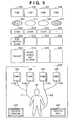
- FIG. 1A block diagram of a medical pump system of the present invention is shown in FIG. 1. In this embodiment, an example of collecting and managing information of four medical pumps is described.
- Reference numeral 100denotes a controller (control unit), which makes up a central portion of this medical pump monitor system, and for the controller, a personal computer having an inputting device such as a keyboard and a pointing device such as a mouse is usually used.
- Reference numeral 101denotes a display (display unit), which displays flow values and alarm information for a plurality of medical pumps of 103, 104, 105 and 106, collected by the controller 100, and the urinary volume from urinary volume meters 111 and the amount of electrolytes (Na + , Ca 2+ , K + , Cl - ) from catheter type censor 112, and displays infusion lines.
- a CRT or a liquid crystal monitoris used for the display (display unit) 101.
- Reference numeral 102denotes a scanner (reading means) for capturing handwritten information of infusion lines
- reference numeral 102adenotes a scanner for reading product identification information (such as bar codes), and they are connected to the controller 100.
- Reference numeral 107denotes communication port expansion device (communication port expanding means) such as a multiplexer for multiplying communication ports when the controller 100 is poorly equipped with ports for communicating with pumps that collect data.
- the controller 100is connected to medical pumps 103, 104, 105 and 106 via this communication port expansion device 107 using a communication cable (wired) 109 or is connected therewith wirelessly.
- the configuration of the controller 100is, for example a configuration as shown in FIG. 9, which comprises a CPU 901, a RAM 902, a ROM 906, a HDD 909, a floppy disk (FD) 906a, a keyboard 904 and a mouse 905, and is connected to a display 101 and is connected via an I/F 903 to the scanner 102. It is further connected via an I/F 907 to the communication port expansion device 107. Also, it is connected to the host computer of a nurse station or the like through an external communication port 107a.
- the controller 100urges an operator to select information of drugs to be administered by respective pumps from a drug database (drug library) file stored in the memory means in the controller 100.
- the operator(medical staff such as a doctor and nurse) selects drugs to be administered such as a vitamin solution for the pump 103, a physiological salt solution for the pump 104 and high calorie medical fluids containing electrolytes such as Na + , Ca 2+ , K + , Cl - for the pump 105.
- the operatorinputs product identification information to the system as medical apparatus identification information (such as bar codes) stuck on respective medical pumps using the scanner 102a for respective medical pumps 103 to 106, and reads product identification information to the system as drug identification information (such as bar codes) 103b, 104b, 105b and 106b syringes 103a and 103b in which drugs are taken in predetermined minutes and which are connected to the pumps or fluid containers 105a and 106a connected to the pumps to make a check on whether or not the drug is one included in the drug database file of the controller 100.
- voice informationis given by voice informing means 908 for calling attention if it is a drug not included in the database file.
- the identification information of this pump and the drug identification informationare stored in the RAM 902 as a pair, and are displayed together on the display unit 101 as shown in FIG. 5.
- the controller 100communicates with four pumps connected as medical pumps 103, 104, 105 and 106 in succession at a fixed time interval (for example one minute interval), wirelessly and/or with cables.
- the communicationis data for requesting information of current flows of administered fluids from respective medical pumps 103, 104, 105 and 106, and when the request data are received by the pumps, the pumps send back the flow information to the controller 100 in predetermined format.
- the controller 100subsequently sends signals requesting alarm information to the connected medical pumps 103, 104, 105 and 106, and when they are received by the pumps, the pumps also send back the alarm information to the controller 100 based on a predetermined format. Furthermore, if there exists no alarm information, then a signal indicating no alarm information is sent back to the controller 100.
- the controller 100displays information from connected medical pumps 103 to 106 on the display (display unit) in such a manner that it is displayed along a pump information display area shown in FIG. 5.
- a region denoted by reference numeral 501is a region in which operation states of medical pumps 103 to 106 are indicated by color, for example by green during normal operations (described with blank in this figure), by red when an alarm is given (described with vertical lines in this figure), by yellow in the case when administration operations are interrupted (described with slashes in this figure) and by gray when the pump itself is not connected. Also, its contents (occlusion, abnormal flows, etc.) are displayed at the same time.
- a region denoted by reference numeral 502is a region in which the flow value of the pump 103 is indicated.
- Reference numeral 503denotes a region in which alarm information currently occurring in the medical pump 103 is indicated, and the region is blanked when no alarm is given.
- Reference numeral 504denotes a region in which drugs that are administered are displayed. The system can be operated even if drugs to be administered are not defined, but in this case, the region is blanked.
- reference numerals 511 to 514denote regions in which information about the medical pump 104 is displayed
- reference numerals 521 to 524denote regions in which information about the medical pump 105 is displayed
- reference numerals 531 to 534denote regions in which information about the medical pump 106 is displayed.
- Reference numeral 540denotes an infusion circuitry display region (infusion circuitry display unit), a region in which a graphic file stored in the controller 100 in predetermined format and file name is displayed.
- the graphic filemay be a general graphic file such as a bit map file and a JPG file in the case where the controller 100 is a personal computer or the like.
- a bit map file of 24 bits color with 640 dots (lateral direction) ⁇ 480 dots (vertical direction)is stored in file name of "C: ⁇ Yuekic.bmp".
- Reference numeral 541denotes a circuitry creation function calling button (circuitry creation function calling means), and by clicking (pressing) the button, an application for creating and modifying infusion circuitry and storing the same as graphic file data, as described later, is started.
- Reference numeral 542denotes a circuitry read function calling button (circuitry read function means), and by clicking (pressing) the button, an application for reading a diagram of infusion circuitry and storing the same as graphic file data, as described later, is started.
- both buttons 541 and 542are expedient buttons displayed on the screen, the click (press) operations are operations of moving a pointer of a pointing device such as a mouse onto the button displayed on the screen and clicking the same.
- a condition displayed in FIG. 5is based on the assumption that a bit map file for displaying infusion circuitry is stored in advance, and information of the medical pump 103 is displayed in the regions 501 to 504.
- a square denoted by numeral 104corresponds to the medical pump 104 of which information is displayed in the regions 511 to 514
- a square denoted by numeral 105corresponds to the medical pump 105 of which information is displayed in the regions 521 to 524
- a square denoted by numeral 106corresponds to the medical pump 106 of which information is displayed in the regions 531 to 534.
- infusion lines 110 running from the medical pump 103 and the medical pump 104are integrated into one line to form a first infusion line L1 to be fixed in administration position near the right brachium part of the patient 27, and infusion lines 110 running from the medical pump 105 and the medical pump 106 are integrated into one line to form a second infusion line L2 to be fixed in administration position near the left thigh part of the patient 27.
- a diagram of infusion circuitryshould be reregistered not only in cases where administration is started for a new patient, but also in cases where administration passes are changed due to change of drugs to be administered for long-term administration.
- a "C: ⁇ Yuekic.bmp" filemay be created anew.
- the "C: ⁇ Yuekic.bmp” filecan be created either by clicking the circuitry creation function calling button 541 or by clicking the circuitry read function calling button 542.
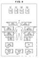
- FIG. 6When the circuitry creation function calling button 541 is clicked, a window is displayed on the display unit as shown in FIG. 6.
- the arrangement of the pumps 103 to 106is displayed by selecting from a plurality of arrangement patterns stored in memory means that is the most suitable for the therapy for the patient.
- reference numerals 601 to 604denote medical pumps as shown in the region 540 in FIG. 5.
- Reference numeral 27denotes a model showing the body of the patient
- reference numerals 606 to 613 around the patient 27denote buttons (selecting means) for selecting the portion of the patient 27 into which injection is made by the infusion line
- reference numerals 606, 607, 608, 609, 610, 611, 612 and 613correspond to a right clavicle, left clavicle, right brachium part, left brachium part, right forearm part, left forearm part, right thigh part and left thigh part, respectively.
- Reference numeral 614denotes a junction production button (junction producing means)
- reference numeral 615denotes a button for making a return by one action in case of erroneous operations
- reference numeral 616denotes an end button (end inputting means) for overwriting the infusion circuitry diagram graphic file "C: ⁇ Yuekic.bmp".
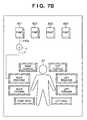
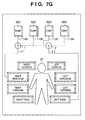
- FIG. 6a procedure of creating an infusion circuitry diagram as shown in the region 540 in FIG. 5 will be described based on FIG. 6 and Figs 7A to 7G, in correspondence with a flow of processing shown in Figs 10A and 10B.
- the start and end points of the linemay be defined one after another.
- flowcharts shown in Figs 10A and 10Bmay be stored in a ROM 906 or a HDD 909 as a program, or may be stored in a CD-ROM, a DVD-ROM, a floppy disk or the like.
- the medical pump 601is clicked.
- the medical pumpgoes into a selection state in which its displayed color is changed or it blinks (FIG. 6, S1003). Since the medical pump 601 is connected to the medical pump 602, the infusion line is created up to the junction 1 with the medical pump 602.
- the operatorsubsequently clicks the junction production button (junction producing means) 614 (S1003).
- the junctionis displayed just below the medical pump 601 with the junction being surrounded by a circle, and an infusion line 110 a is formed in the middle between the medical pump 601 and the junction 1 (FIG. 7A, S1004).
- the junction 1 surrounded by the circleis first clicked. In this condition, the junction 1 goes into the selection state (the color inside the circle highlighted, and so on), and subsequently a right brachium part selection button 608 is clicked (S1018). Furthermore, the order of clicking the junction and the right brachium part selection button in this case may be reversed. In this way, the first infusion line L1 is formed from the junction 1 to the right brachium part of the patient (state shown in FIG. 7B, S1019).
- the junction 1 and the medical pump 602are clicked one after another, whereby an infusion line 110b is formed from the junction 1 to the medical pump 602 (FIG. 7C, S1018, S1019).
- the order of clickingmay be reversed as well.
- a line in which the medical pumps 603 and 604 are jointed at some midpoint and a medical fluidis injected into the patient at the left thigh part.
- the medical pump 603 and the junction production button 614are clicked one after another, whereby a new junction 2 is displayed below the medical pump 603 with the junction 2 being surrounded by a circle (S1003), and an infusion line 110c is formed in the middle between the medical pump 603 and the junction 2 (FIG. 7D, S1004).
- this junction 2 and the left thigh part selection button 613are clicked to form the second infusion line L2 from the junction 2 to the left thigh part of the patient (FIG. 7E, S1018, S1019).
- the medical pump 604 and the new junction 2are clicked one after another, thereby completing the infusion line 110c (FIG. 7F, S1018, S1019).
- the operatormistakenly clicks the left thigh part selection button 607 after clicking the medical pump 604, the infusion line L2 from the medical pump 604 will directly run into the left thigh part of the patient without passing through the junction 2. If the operator notices the operational error at this time, he or she may click the return button 615.
- the return buttonis clicked once, whereby finally conducted action (clicking of the left thigh part selection button in this case) is determined as being invalid, and the state in which the medical pump 604 is selected is provided.
- the created diagram of infusion circuitryis created as a bmp file format, and is stored in the name of "C: ⁇ Yuekic.bmp".
- an interruption button for interrupting processing to end the infusion circuitry creation functionmay be provided.
- the junctionis considered as a point, but in the case where transfusion using three-way stop cocks, Yshaped-tubes, Tshaped-tubes and the like is conducted, a three-way stop cock button and a Yshaped-tube button are provided in place of the junction production button, thereby making it possible accommodate the situation.
- bit map fileis created in this embodiment, the history of operational actions is recorded in other format separately, thereby making it possible to cope flexibly with the situation in which infusion circuitry is slightly changed.
- the file in which the previous operational action is recordedis read at the time when an infusion circuitry creation window is displayed, the line is drawn in accordance therewith, and selection of each drawing action is enabled, thereby making it possible to cope quickly with the slight modification from the previously created circuitry. Buttons and the like in the window in that case are placed as shown in FIG. 8. In comparison with FIG. 6, the return button is absent, and a history back button 801, a history proceeding button 802 and a line deletion button 803 are newly created.
- the drawn lineis selected in reverse chronological order (S1005, S1006).
- the history back buttonis once clicked, the infusion line between the right-hand junction and the pump 604 is selected.
- the history back buttonis selected once again, the state in which the infusion line between the right-hand junction and the pump 604 is selected is released, and the infusion line between the right-hand junction and the left thigh part is selected.
- the history back buttonis clicked three times after the time when the window appears. Thereby, the line drawn between the medical pump 603 and the right-hand junction is selected.
- the line deletion buttonis clicked in this condition, followed by clicking the medical pump 603 and the right-hand junction one after another, whereby the infusion line is drawn between the medical pump 603 and the right-hand junction (FIG. 7G).
- the infusion circuitry creation functionis ended after the bit map file is stored (S1017) and normal pump monitor processing is carried out, but at this time, processing of updating the infusion circuitry diagram display region 540 to the new bit map file is carried out.
- the administration pass to the patientis selected from a plurality of buttons in this embodiment, but this is for the purpose of easy determination of the position of the line, and if it is desired that more detailed positions are identified, methods in which the number of buttons is further increased, click is made directly on the model picture of the patient, and so on can also be adopted.
- the infusion circuitry diagram read function start button 542is clicked, whereby the scanner 102 is controlled from the controller 100, and the circuitry diagram set in the scanner 102 is read in the system, and is stored in a format as in the case of the creation of infusion circuitry described previously and in the same name of "C: ⁇ Yuekic.bmp".
- the systemcan create the infusion circuitry diagram using the creation function, and display/manage the diagram without classifying cases either when a registration is made or when the scanner 102 is used to read the diagram for making a registration.
- the scanner 102is used as means for capturing an infusion circuitry diagram such as a handwritten diagram in this embodiment, but it is apparent that similar effects can be obtained by photographing the handwritten infusion circuitry diagram by a digital camera and having the memory medium of the digital camera read by the controller.
- the medical pump system of the present inventionit is possible to provide a system in which the operation conditions of a plurality of medical pumps are monitored for one patient with a function of creating and editing an infusion line from the pump to the patient on each-by-each basis, and display information created and edited by means of this function displayed on the system, thus making it much easier to confirm (monitor) the current states of infusion lines.
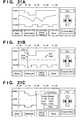
- FIGS. 21A to 21Cshow a trend graph of the amount of water displayed after computing the total of the amount of water introduced by all the medical pumps that are used (Intake) and the amount of water discharged as urine (Output) is shown.
- the range of ml/hcan be changed by pressing (clicking) a "+” or “-” key.
- the amount of water in any time rangecan be displayed by using " ⁇ " or " ⁇ ”.
- FIG. 21Ashows a trend graph of the balance of water (Intake and Output) at the current time.
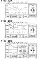
- FIG. 22A to 22Cshow a trend graph of the amount of Na+ as one example of electrolytes displayed after computing the total of the electrolytes (Na + , Ca 2+ , K + , Cl - , etc.) introduced by all the medical pumps that are used or computing the data from the sensor 112.
- the range of mEgcan be changed by pressing a "+” or "-” key.
- the amount of electrolytes in an arbitrary time rangecan be displayed by performing operations similar to those in FIGS . 21A to 21C and using " ⁇ " and " ⁇ ".
- these totals and trend graphscan be used as diagnostic/therapeutic data at different location by downloading them to the FD 906a or sending them to the host computer or the like through the external port 107a.
- An alarmis given when the amount of the electrolyte exceeds a preset input value (threshold) .
- the screenmay be reduced into quarters to display the amounts of four electrolytes of Na + , Ca 2+ , K + , Cl - .
- FIG. 11is a block diagram of the present invention.
- an example of connection of three external apparatuses including medical devises and the likesuch as infusion pumps, syringe pumps, body pressure monitors, body temperature monitors, urinary volume monitors and electrocardiographs is shown, but this number of apparatuses can be arbitrarily increased or decreased.
- An external apparatus 1 (1121)is connected through a communication cable to a communication port (external communication unit) 1 (1111) of this system (1105).
- an external apparatus 2 (1122) and an external apparatus 3 (1123)are connected to a communication port (external communication unit) 2 (1112) and a communication port (external communication unit) 3 (1113), respectively, in a one-to-one correspondence.
- Communication ports 1(1111), 2(1112) and 3(1113)are brought together in a communication unit (1104).
- a variety of configurationsare possible such as a microcomputer control communication board to make connection to a plurality of communication ports and a multiplexer type to switch ports for communication when they are used.
- Signals obtained from the communication unit (1104)are stored in storing means (1103), and are sent to a comparison unit (1102) simultaneously.
- the comparison unitcompares operation (operating) information of the connected external apparatuses 1(1121), 2(1122) and 3(1123) sent from the communication unit (1104) with operation (operating) information of the previous external apparatuses 1(1121), 2(1122) and 3(1123) stored in the storing unit (1103), and sends a non-change signal to a control unit (1101) if there is no difference, and sends a differential signal to the control unit (1101) if there is a difference.
- the control unit (1101)changes the contents of the display unit based on the signal from the above described comparison unit.
- the communication unit (1104) and the communication ports (1111 to 1113) in FIG. 11correspond to the controller 100 in FIG. 1.
- a program corresponding to the flowchart shown in FIG. 20may be stored in the storing unit (1103) in FIG. 11, or may be provided by a CD-ROM and the like.
- FIG. 12A screen configuration on the display unit 1100 of the system of the present invention is shown in FIG. 12.
- the flow values of the flow meter 1, of the flow meter 2 and of the flow meter 3are displayed in textbox objects 1(1201), 2(1202) and 3(1203), respectively in such a manner that their actual placement can be visually confirmed.
- the total flow value obtained by adding up the values of the flow meters 1, 2 and 3is displayed in a textbox object 4 (1204).
- Communication between the system (1105) and the flow meters 1, 2 and 3will be described as a command respond mode in which the current flow values of the flow meters 1, 2 and 3 are sent back when request signals from the communication unit (1104) are received, but it can also be configured with a mode in which signals from the flow meters 1, 2 and 3 are unilaterally sent to the host system at a fixed time interval in an asynchronous manner, and so on.
- signals showing the start and end of the signalsuch as STX and ETX and checksum signals are often added, but these signals are omitted in this embodiment.
- flow value signals from the flow meters 1, 2 and 3show 2-byte numbers of four figures in BCD code with the unit of 0.1 ml/h.
- the flow value signalshows a flow value of 190.0 ml/h when a 2-byte code of 1900 in hexadecimal digit data is sent.
- the storing unit (1103)needs an area of six bites in total for storing two bytes of information from three flow meters 1, 2 and 3, respectively. For example, if the flow values of the flow meters 1, 2 and 3 are 100.0 ml/h, 200.0 ml/h and 300.0 ml/h, respectively, information as shown in FIG. 13 is stores in the 6-byte area of the storing unit (1103).
- the communication unit (1104)sends request signals to the flow meters 1, 2 and 3 (S2001), performs processing of receiving flow values from the flow meters 1, 2 and 3 for the three flow meters 1, 2 and 3 one after another (S2002), and sends the data to the comparison unit (1102) at the time of obtaining the flow values from the three flow meters 1, 2 and 3 (S2003).
- the comparison unit (1102)compares the signal sent from the communication unit (1104) with the data stored in the storing unit (1103) (S2004), and sends a non-change signal (for example, a hexadecimal digit 1-byte signal of AA in hexadecimal digits) to the control unit (1101) if the data equal each other (S2006). If information of the binary of the flow meters 1, 2 and 3 stored in the storing unit (1103) is of 1000 in hexadecimal digits, the signal sent from the communication unit (1104) is of 1200 in hexadecimal digits, a 3 byte-signal of 021200 in hexadecimal digits is sent to the control unit (1101).
- a non-change signalfor example, a hexadecimal digit 1-byte signal of AA in hexadecimal digits
- the "02" equivalent to the first byte number in this caseis a number corresponding to the connected flow meters 1, 2 and 3, and if the flow meter of which flow value is changed is the flow meter denoted by 3, this value will be "03".
- the differential signalis represented by "external apparatus number" + "flow value” in the embodiment.
- the control unit (1101)does not perform change/control of the display unit (1100) if the signal from the comparison unit (1103) is a non-change signal, and if a signal with the flow changed is sent, the control unit (1101) sends to the display unit (1100) processing instructions to change the displayed contents of the display unit (1100) based on the signal with the flow changed. If a signal of 021400 in hexadecimal digits is sent from the comparison unit (1102) when the contents shown in FIG. 12 are displayed on the display unit (1100), the contents of the display unit (1100) are rewritten to those as shown in FIG. 14. Specifically, the contents of the textbox 2 (1402) are rewritten from 120.0 ml/h to 140. 0 ml/h, and following this change, the total flow value in the textbox object 4 (1404) is rewritten 365.0 ml/h to 385.0 ml/h.
- the signal with the flow changedis represented by "the number of the flow meter with the flow changed" + “the flow value after changing” in the embodiment, but in the case where values of two or more flow meters are changed, two signals put together may be sent. For example, if the flow value of the flow meter 1 is changed from 90.0 ml/h to 100.0 ml/h, and the flow value of the flow meter 3 is changed from 120.0 ml/h to 80 ml/h, a 6-byte signal of 011000030800 in hexadecimal digits may be sent as for a signal that is sent from the comparison unit to sending means.
- the control unit (101) of a masterneeds processing consistent with the byte number of the differential signal, thus putting a burden on information processing (signal processing).
- all the flow values among the external apparatuses 1 (1121), 2(1122) and 3(1123)may be sent if at least one of all the flow values of the external apparatuses 1(1121), 2(1122) and 3(1123) is changed.
- the byte number of the differential signalis constant 9 bytes, a burden on information processing (signal processing) can be reduced.
- changescan be made as appropriate depending on the number of external apparatuses connected to the system (1105), the frequency of changing external apparatuses and the importance of patient monitor information.
- operation information(operation signals) among the external apparatuses 1(1121), 2(1122) and 3(1123) are received in succession, and past operation information stored in the storing unit (1103) and operation information currently received from the external apparatuses 1(1121), 2(1122) and 3(1123) are outputted.
- the comparison unit (1102)compares the past operation information with the current operation information, generates information (differential information) showing a difference between the past operation information and the current operation information and sends the information to the control unit (1101).
- the control unitmay avoid performing change/control of the display unit unless there is no substantial difference, thus making it possible to reduce a burden on information processing even if a large number of external apparatuses such as medical pumps are used.
- the information showing a differenceis constituted at least by the aforesaid external apparatus number (information indicating an external apparatus sending current information different from the past information it sent), whereby the amount of information to be sent to the control unit can be reduced as compared with operation information from the external apparatus, and this reduction of the amount of information also makes it possible to reduce a burden on information processing (signal processing) in the control unit.
- the control unitdoes not need to dispatch the request signal, thereby making it possible to reduce a burden on information processing (signal processing) in the control unit. Consequently, a monitoring system can be built, which causes no drop in response when the control unit concurrently performs processings of the keyboard and various kinds of switches (not shown) as HMI (Human Machine Interface).
- HMIHuman Machine Interface
- the contents in the storing unit (1103)is set 0 (or data outside the normal range) at the time of starting the system, whereby the data of all the flow meters are sent to the control unit (1101) because the data of the flow meters 1, 2 and 3 obtained from the communication unit (1104) are different from the information stored in the storing unit (1103), and the latest flow values of the flow meters are automatically displayed on the display unit (1100) when the system starts.
- FIG. 15communication data obtained by the communication unit in the case of large amount of information is shown.
- a slave addressshowing a number of a slave (external apparatus) and data comprised of operation conditions of slaves are exist between a header such as STX and a terminator such as ETX.
- datasuch as operation conditions are decomposed out of received data (decomposition A). Coding by exclusive OR (XOR) (BCC: Block Check Character) is performed for data of this decomposition A by each word from the heading, what is finally produced is considered as BCC 1 (Type I transformation).
- XORexclusive OR
- BCC 2(Type II transformation)Furthermore, with an inverse (NOT) of the decomposition A is being decomposition B, and coding by summation by each word (ADD) is performed for data of this decomposition B, and what is finally produced is considered as BCC 2(Type II transformation). These adopt lower 16 bits. Data change is considered to have occurred, from changes in BCC1 and BCC2. BCC coding is generally used and its reliability is acknowledged, but further coding processing is performed using reversed data in calculation, and two BCCs having no causal relation are compared with each other, thereby improving safety. Due to this safety, the amount of data can be reduced as shown in FIG. 16 without storing all received data to shorten memory access time. Also, if the received signal includes BCC in advance, the BCC data is directly used, whereby the above described decomposition work and calculation processing can be reduced and further enhancement of the speed can be expected.
- FIG. 17A series of the flow thereof will be described using FIG. 17.
- a portion of data in which the operation conditions of slaves and the like(decomposition A) is fetched out of the communication data, and XOR computation of 16 bits thereof is performed to provide BCC1.
- BCC2lower 16 bits resulting from ADD computation of decomposition B are considered as BCC2 (Step S1700).
- a slave addressis read from the communication data, and the past BCC1 and BCC2 corresponding to this address are read from the storing unit (1103) (Step S1701).
- the current BCC2is compared with the past BCC2 read from the storing unit, and advancement to Step S1704 is made if their contents are different from each other, and advancement to Step S1703 is made if their contents are identical to each other (Step S1702). If their contents are identical to each other in Step S1702, the current BCC1 is compared with the past BCC1 read from the storing unit (1103), and advancement to Step S1704 is made if their contents are different from each other, and processing is ended without communicating with the host based on the assumption that the communication condition for the slave address remains unchanged if their contents are identical to each other (Step S1706).
- Step S1704If the current data and the past data are different from each other in Step S1702 and Step S1703, BCC1 and BCC2 are written along with the corresponding slave address (Step S1704).
- Information of change of operation conditions and the likeis sent to the external apparatus corresponding to the slave address (Step S1705) and processing is ended (Step S1706).
- the number of bytes to be subjected to comparisoncan be reduced to shorten processing time
- data to be storedcan be reduced to the minimum to speed up time of read/write in the storing unit (1103), and communication time can also be reduced because only data associated with change in slaves is sent to the host.
- a protocolsuch that no signals are sent to the host in the case of no changes is presented in FIG. 17, but it is easy to make a modification thereto so that a short non-signal change is sent.
- parity dataequivalent data
- Figs 18 and 19show a method of detecting the position of changed data. Structures of BCC data and parity data for data such as the operation condition of the slave are shown in FIG. 18. Processing is performed as in the case of FIG. 15 in the previous example with respect to BCC, and for this data, parity data having parity codes corresponding to the bit of each 1-byte data put together on an eight-by-eight basis is also to be checked as data of the vertical component, in addition to the lateral check system.
- parity dataare aligned in succession after each slave address, and after that, BCC1 and BCC2 similar to those shown in FIG. 16 are stored.
- parity dataare data of P1, P2, P3 and Pn. Pn increases/decreases with the increase/decrease of communication data 8 bytes. The processing flow thereof is similar to that shown in FIG.
- Step S1702 and Step S1703if it is determined in Step S1702 and Step S1703 that the past BCC data and the current BCC data are different from each other, past parity data is compared with current parity data for each parity data before the BCC data is written in the memory, parity data with difference found and the BCC data are written in a corresponding memory area, and the data and the slave address corresponding to the parity subjected to change are selectively sent to the host.
- the flow value of the slave for initial 8 bytes of the data, information associated with supplied voltage of the flow meter for next 8 bytes of the data, alarm information associated with the number of rotations of the apparatus for subsequent 8 bytes of the data, and continuous operation time for final 8 bytes of the dataare sent. If difference is found for the parity of the third byte in a slave, only alarm information associated with the number of rotations for a corresponding slave address may selectively be sent, and thus host sending time can be reduced significantly, leading to reduction in total time.
- operation states, alarm information, etc. of external apparatusesincluding a plurality of medical apparatuses such as infusion pumps, syringe pumps and blood pressure monitors having a large amount of send data can be monitored in real time.
Landscapes
- Health & Medical Sciences (AREA)
- Engineering & Computer Science (AREA)
- General Health & Medical Sciences (AREA)
- Public Health (AREA)
- Life Sciences & Earth Sciences (AREA)
- Veterinary Medicine (AREA)
- Animal Behavior & Ethology (AREA)
- Hematology (AREA)
- Heart & Thoracic Surgery (AREA)
- Biomedical Technology (AREA)
- Vascular Medicine (AREA)
- Anesthesiology (AREA)
- Bioinformatics & Cheminformatics (AREA)
- Primary Health Care (AREA)
- Medical Informatics (AREA)
- Chemical & Material Sciences (AREA)
- Medicinal Chemistry (AREA)
- Epidemiology (AREA)
- Infusion, Injection, And Reservoir Apparatuses (AREA)
- Reciprocating Pumps (AREA)
- Electromagnetic Pumps, Or The Like (AREA)
Abstract
Description
Claims (22)
- A medical pump monitor system using a plurality ofmedical pumps to administer medical fluids and the like fora patient, monitoring flows of delivered fluids and alarminformation of the medical pumps through cablecommunication and/or wireless communication,
wherein infusion circuitry creating means forsetting/changing the connection conditions of infusionlines from the plurality of medical pumps, andadministration passes and/or administration positions forthe patient is provided, and it is made possible to displayinfusion circuitry data created in the infusion circuitrycreating means on a monitor screen by operations by anoperator of the medical pump monitor system. - The pump monitor system according to claim 1, whereinreading means for reading an infusion circuitry diagramsuch as a handwritten diagram in the medical pump monitorsystem is provided, and it is made possible to make a choiceby operator's operations on whether infusion circuitryinformation to be displayed during operation of the medicalpump monitor system is information created using theinfusion circuitry creating means or information createdusing said infusion circuitry diagram reading means.
- The medical pump monitor system according to claim 1,wherein said infusion circuitry creating means displays a sketch of the patient with respect to determination of theadministration position for the patient, and inputting inthe medical pump monitor system any position informationin the sketch, thereby making a determination asadministration closest to the inputted positioninformation.
- The medical pump monitor system according to claim 1,wherein said infusion circuitry creating means furthercomprises determining means for making a check for theinfusion line not suited to a practical method fortransfusion.
- The medical pump monitor system according to claim 1,wherein said fluid delivery circuitry creation means canselect an optimal pump arrangement pattern from a pluralityof pump arrangement patterns registered in advance.
- The medical pump monitor system according to claim 1,wherein the determining means makes a determination onexistence of loop-shaped lines in the infusion line, andgives an alarm to the operator if there exist a loop shapedline.
- The medical pump monitor system according to claim 1,wherein the determining means determines whether two ormore of the infusion lines run directly from the medical pump, and gives an alarm to the operator if two or more ofinfusion lines run directly therefrom.
- The medical pump monitor system according to claim 1,wherein the determining means determines whether theinfusion line is ended at some midpoint without reachingthe patient, and gives an alarm to the operator of themedical pump monitor system if the infusion line is endedat some midpoint.
- The medical pump monitor system according to claim 1,wherein the determining means determines whether theinfusion line is necessarily formed towards at least oneposition of the patient from the medical pump, and givesan alarm to the operator if the infusion line is notnecessarily formed towards at least one position of thepatient from the medical pump.
- The medical pump monitor system according to claim 1,wherein the determining means determines whether theinfusion line inserted into a specified portion of thepatient is inserted into the patient again, and gives analarm to the operator if the infusion line inserted intoa specified portiion of the patient is inserted into thepatient again.
- The medical pump monitor system according to claim 1,wherein the determining means determines whether theinfusion line from the operating medical pump is notconnected to the patient, and gives an alarm to the operatorif the infusion line from the operating medical pump is notconnected to the patient.
- The medical pump monitor system according to claim 1,wherein the monitor screen can display thereon real-timestates or trends in arbitrary time ranges for at least anyone of the amount of water, the urinary volume and the amountof electrolytes.
- A controlling method for a medical pump monitor systemusing a plurality of medical pumps to administer medicalfluids and the like for a patient, monitoring flows ofdelivered fluids and alarm information of the medical pumpsthrough cable communication and/or wireless communication,comprising:an infusion circuitry creating step ofsetting/changing the connection conditions of infusionlines from the plurality of medical pumps, andadministration passes and/or administration positions forthe patient; anda step of making it possible to display infusioncircuitry data created in the infusion circuitry creating means on a monitor screen by operations by an operator ofthe medical pump monitor system.
- A computer readable memory storing therein programcodes for controlling a medical pump monitor system usinga plurality of medical pumps to administer medical fluidsand the like for a patient, monitoring flows of deliveredfluids and alarm information of the medical pumps throughcable communication and/or wireless communication,comprising program codes of:an infusion circuitry creating step ofsetting/changing the connection conditions of infusionlines from the plurality of medical pumps, andadministration passes and/or administration positions forthe patient; anda step of making it possible to display infusioncircuitry data created in the infusion circuitry creatingmeans on a monitor screen by operations by an operator ofthe medical pump monitor system.
- A real-time monitoring system performing real timecommunication with external apparatuses including one ormore medical apparatuses, and controlling the externalapparatuses and/or displaying the conditions of theexternal apparatuses, comprising:communicating means for communicating with theexternal apparatuses;displaying means for displaying the conditions of theexternal apparatuses;storing means for storing one or more pastcommunication data obtained by the communicating means;comparing means for comparing currently communicateddata with past data; andcontrolling means for controlling contents to bedisplayed on the displaying means, based on signals fromthe comparing means,wherein the comparing means reduces the amount of thedata and/or eliminates the amount of the data for the amountof signals to be sent to the controlling means, in the casewhere the past data and the current data are identical toeach other in comparison with the case where the past dataand the current data are different from each other.
- A real-time monitoring system performing real timecommunication with external apparatuses including one ormore medical apparatuses, and controlling the externalapparatuses and/or displaying the conditions of theexternal apparatuses, comprising:communicating means for communicating with theexternal apparatuses;displaying means for displaying the conditions of theexternal apparatuses;storing means for storing one or more pastcommunication data obtained by the communicating means;comparing means for comparing currently communicateddata with past data; andcontrolling means for controlling contents to bedisplayed on the displaying means, based on signals fromthe comparing means,wherein the comparing means selectively sends only aportion where the past data and the current data aredifferent from each other, for the signals to be sent tothe controlling means.
- The real-time monitoring system according to claim 15,wherein the communicating means, the comparing means andthe storing means are unified, and are separated from thedisplaying means and the controlling means.
- The real-time monitoring system according to claim 15,wherein the external apparatuses is medical apparatusescomprising communicating means such as infusion pumps andurinary volume meters, and contents that are displayed onthe displaying means are operation and stop information,flows, alarm conditions from apparatuses, information ofadministrated drugs, administration information andpatient information.
- A controlling method for a real-time monitoring systemperforming real time communication with externalapparatuses including one or more medical apparatuses, and controlling the external apparatuses and/or displaying theconditions of the external apparatuses, comprising stepsof:storing in storing means one or more pastcommunication data obtained by communicating means forcommunicating with the external apparatuses;comparing currently communicated data with past databy comparing means; andcontrolling contents to be displayed on the displayingmeans, based on signals from the comparing means,wherein said method comprises a step in which thecomparing means performs control to reduce the amount ofthe data and/or eliminate the amount of the data for theamount of signals to be sent to the controlling means, inthe case where the past data and the current data areidentical to each other in comparison with the case wherethe past data and the current data are different from eachother.
- A controlling method for a real-time monitoring systemperforming real time communication with externalapparatuses including one or more medical apparatuses, andcontrolling the external apparatuses and/or displaying theconditions of the external apparatuses, comprising stepsof:storing in storing means one or more pastcommunication data obtained by communicating means forcommunicating with the external apparatuses;comparing currently communicated data with past databy comparing means; andcontrolling contents to be displayed on the displayingmeans, based on signals from the comparing means,wherein said method comprises a step in which thecomparing means selectively sends only a portion where thepast data and the current data are different from each other,for the signals to be sent to the controlling means.
- A computer readable record medium storing thereinprogram codes of a controlling method for a real-timemonitoring system performing real time communication withexternal apparatuses including one or more medicalapparatuses, and controlling the external apparatusesand/or displaying the conditions of the externalapparatuses, comprising program codes of steps of:storing in storing means one or more pastcommunication data obtained by communicating means forcommunicating with the external apparatuses;comparing currently communicated data with past databy comparing means; andcontrolling contents to be displayed on the displayingmeans, based on signals from the comparing means,wherein said computer readable record mediumcomprises a program code of a controlling step in which thecomparing means performs control to reduce the amount ofthe data and/or eliminate the amount of the data for theamount of signals to be sent to the controlling means, inthe case where the past data and the current data areidentical to each other in comparison with the case wherethe past data and the current data are different from eachother.
- A computer readable record medium storing thereinprogram codes of a controlling method for a real-timemonitoring system performing real time communication withexternal apparatuses including one or more medicalapparatuses, and controlling the external apparatusesand/or displaying the conditions of the externalapparatuses, comprising program codes of steps of:storing in storing means one or more pastcommunication data obtained by communicating means forcommunicating with the external apparatuses;comparing currently communicated data with past databy comparing means; andcontrolling contents to be displayed on the displayingmeans, based on signals from the comparing means,wherein said computer readable record mediumcomprises a program code of a step in which the comparingmeans selectively sends only a portion where the past data and the current data are different from each other, for thesignals to be sent to the controlling means.
Applications Claiming Priority (4)
| Application Number | Priority Date | Filing Date | Title |
|---|---|---|---|
| JP2000161155 | 2000-05-26 | ||
| JP2000161155AJP4608053B2 (en) | 2000-05-26 | 2000-05-26 | Medical pump monitor system capable of displaying infusion circuit diagram, control method thereof, and computer-readable memory |
| JP2000352537AJP4279985B2 (en) | 2000-11-15 | 2000-11-15 | Real-time monitoring system and control method thereof, program storage medium |
| JP2000352537 | 2000-11-15 |
Publications (3)
| Publication Number | Publication Date |
|---|---|
| EP1157711A2true EP1157711A2 (en) | 2001-11-28 |
| EP1157711A3 EP1157711A3 (en) | 2002-01-02 |
| EP1157711B1 EP1157711B1 (en) | 2008-05-28 |
Family
ID=26592962
Family Applications (1)
| Application Number | Title | Priority Date | Filing Date |
|---|---|---|---|
| EP01304659AExpired - LifetimeEP1157711B1 (en) | 2000-05-26 | 2001-05-25 | Medical pump monitoring system |
Country Status (4)
| Country | Link |
|---|---|
| US (2) | US20020013551A1 (en) |
| EP (1) | EP1157711B1 (en) |
| AT (1) | ATE396760T1 (en) |
| DE (1) | DE60134191D1 (en) |
Cited By (33)
| Publication number | Priority date | Publication date | Assignee | Title |
|---|---|---|---|---|
| WO2006008465A1 (en)* | 2004-07-16 | 2006-01-26 | Alaris Medical U.K. Limited | Infusion apparatus |
| EP1744262A3 (en)* | 2003-11-13 | 2007-03-28 | Hospira, Inc. | System for maintaining drug information and communicating with medication delivery devices |
| ES2330298A1 (en)* | 2008-06-23 | 2009-12-07 | Jaime Vazquez Torruella | Electromechanical assembly for treating the urinary system |
| US8065161B2 (en) | 2003-11-13 | 2011-11-22 | Hospira, Inc. | System for maintaining drug information and communicating with medication delivery devices |
| CN103379930A (en)* | 2011-02-08 | 2013-10-30 | 泰尔茂株式会社 | Medical pump system and rack for mounting medical pumps |
| CN104984437A (en)* | 2015-07-21 | 2015-10-21 | 苏州麦德迅医疗科技有限公司 | Infusion pump with double-chip architecture and method |
| CN107899111A (en)* | 2017-11-07 | 2018-04-13 | 广东顺德工业设计研究院(广东顺德创新设计研究院) | Inject method for controlling pump and device, computer equipment and storage medium |
| US9971871B2 (en) | 2011-10-21 | 2018-05-15 | Icu Medical, Inc. | Medical device update system |
| US10042986B2 (en) | 2013-11-19 | 2018-08-07 | Icu Medical, Inc. | Infusion pump automation system and method |
| US10242060B2 (en) | 2006-10-16 | 2019-03-26 | Icu Medical, Inc. | System and method for comparing and utilizing activity information and configuration information from multiple medical device management systems |
| US10238801B2 (en) | 2009-04-17 | 2019-03-26 | Icu Medical, Inc. | System and method for configuring a rule set for medical event management and responses |
| US10238799B2 (en) | 2014-09-15 | 2019-03-26 | Icu Medical, Inc. | Matching delayed infusion auto-programs with manually entered infusion programs |
| US10311972B2 (en) | 2013-11-11 | 2019-06-04 | Icu Medical, Inc. | Medical device system performance index |
| US10314974B2 (en) | 2014-06-16 | 2019-06-11 | Icu Medical, Inc. | System for monitoring and delivering medication to a patient and method of using the same to minimize the risks associated with automated therapy |
| US10333843B2 (en) | 2013-03-06 | 2019-06-25 | Icu Medical, Inc. | Medical device communication method |
| US10434246B2 (en) | 2003-10-07 | 2019-10-08 | Icu Medical, Inc. | Medication management system |
| US10692595B2 (en) | 2018-07-26 | 2020-06-23 | Icu Medical, Inc. | Drug library dynamic version management |
| GB2580307A (en)* | 2018-12-12 | 2020-07-22 | Osama Al Baalbaky Alaa | Smart self-monitored syringe infusion pump |
| US10741280B2 (en) | 2018-07-17 | 2020-08-11 | Icu Medical, Inc. | Tagging pump messages with identifiers that facilitate restructuring |
| US10765799B2 (en) | 2013-09-20 | 2020-09-08 | Icu Medical, Inc. | Fail-safe drug infusion therapy system |
| US10861592B2 (en) | 2018-07-17 | 2020-12-08 | Icu Medical, Inc. | Reducing infusion pump network congestion by staggering updates |
| US10898641B2 (en) | 2014-04-30 | 2021-01-26 | Icu Medical, Inc. | Patient care system with conditional alarm forwarding |
| US11007315B2 (en) | 2019-08-22 | 2021-05-18 | Chs Healthcare Ventures, Inc. | Fluidic medical treatment identification |
| US11309070B2 (en) | 2018-07-26 | 2022-04-19 | Icu Medical, Inc. | Drug library manager with customized worksheets |
| US11328805B2 (en) | 2018-07-17 | 2022-05-10 | Icu Medical, Inc. | Reducing infusion pump network congestion by staggering updates |
| US11574737B2 (en) | 2016-07-14 | 2023-02-07 | Icu Medical, Inc. | Multi-communication path selection and security system for a medical device |
| US11571508B2 (en) | 2013-08-30 | 2023-02-07 | Icu Medical, Inc. | System and method of monitoring and managing a remote infusion regimen |
| US11587669B2 (en) | 2018-07-17 | 2023-02-21 | Icu Medical, Inc. | Passing authentication token to authorize access to rest calls via web sockets |
| US11605468B2 (en) | 2015-05-26 | 2023-03-14 | Icu Medical, Inc. | Infusion pump system and method with multiple drug library editor source capability |
| US11852884B2 (en) | 2021-01-19 | 2023-12-26 | CHS Healthcare Ventures, Inc | Systems and methods for controlling microorganism load with an electronic illuminator |
| US12130910B2 (en) | 2019-05-08 | 2024-10-29 | Icu Medical, Inc. | Threshold signature based medical device management |
| US12303464B2 (en) | 2020-04-03 | 2025-05-20 | Icu Medical, Inc. | Systems, methods, and components for transferring medical fluids |
| US12431238B2 (en) | 2020-09-05 | 2025-09-30 | Icu Medical, Inc. | Identity-based secure medical device communications |
Families Citing this family (82)
| Publication number | Priority date | Publication date | Assignee | Title |
|---|---|---|---|---|
| DE10057781B4 (en)* | 2000-11-22 | 2005-08-11 | Siemens Ag | Apparatus and method for optimizing the medical diagnosis workflow |
| US10173008B2 (en) | 2002-01-29 | 2019-01-08 | Baxter International Inc. | System and method for communicating with a dialysis machine through a network |
| WO2005039675A1 (en)* | 2003-10-29 | 2005-05-06 | Nemoto Kyorindo Co., Ltd | Medicinal liquid infusion apparatus |
| US7092796B2 (en)* | 2003-11-14 | 2006-08-15 | Cardinal Health 303, Inc. | System and method for verifying connection of correct fluid supply to an infusion pump |
| US8020564B2 (en) | 2003-12-01 | 2011-09-20 | Carefusion 303, Inc. | System and method for analyzing medical treatment data |
| US7736354B2 (en) | 2004-09-09 | 2010-06-15 | Plc Medical Systems, Inc. | Patient hydration system with hydration state detection |
| US7837667B2 (en) | 2004-09-09 | 2010-11-23 | Plc Medical Systems, Inc. | Patient hydration system with abnormal condition sensing |
| US7758562B2 (en)* | 2004-09-09 | 2010-07-20 | Plc Medical Systems, Inc. | Patient hydration system with a redundant monitoring of hydration fluid infusion |
| US11213621B2 (en) | 2004-09-09 | 2022-01-04 | Reprieve Cardiovascular, Inc. | Fluid therapy method |
| US7938817B2 (en) | 2004-09-09 | 2011-05-10 | Plc Medical Systems, Inc. | Patient hydration system and method |
| US20180185577A9 (en) | 2004-09-09 | 2018-07-05 | Plc Medical Systems, Inc. | Fluid therapy method |
| US7758563B2 (en) | 2004-09-09 | 2010-07-20 | Plc Medical Systems, Inc. | Patient hydration monitoring and maintenance system and method for use with administration of a diuretic |
| US7727222B2 (en)* | 2004-09-09 | 2010-06-01 | Plc Medical Systems, Inc. | Patient hydration system with taper down feature |
| US7945452B2 (en)* | 2005-04-11 | 2011-05-17 | Hospira, Inc. | User interface improvements for medical devices |
| US7896842B2 (en)* | 2005-04-11 | 2011-03-01 | Hospira, Inc. | System for guiding a user during programming of a medical device |
| US20060258985A1 (en)* | 2005-05-11 | 2006-11-16 | Russell Claudia J | Graphical display of medication limits and delivery program |
| US20070088333A1 (en)* | 2005-10-13 | 2007-04-19 | G&L Consulting, Llc | Method and system for infusing an osmotic solute into a patient and providing feedback control of the infusing rate |
| US20070233049A1 (en)* | 2006-03-28 | 2007-10-04 | Hospira, Inc. | Medication administration and management system and method |
| US8075513B2 (en) | 2006-10-13 | 2011-12-13 | Plc Medical Systems, Inc. | Patient connection system for a balance hydration unit |
| US8579853B2 (en)* | 2006-10-31 | 2013-11-12 | Abbott Diabetes Care Inc. | Infusion devices and methods |
| US8317752B2 (en)* | 2007-12-18 | 2012-11-27 | Hospira, Inc. | Touch screen system and navigation and programming methods for an infusion pump |
| US9026370B2 (en) | 2007-12-18 | 2015-05-05 | Hospira, Inc. | User interface improvements for medical devices |
| US8057679B2 (en) | 2008-07-09 | 2011-11-15 | Baxter International Inc. | Dialysis system having trending and alert generation |
| US10089443B2 (en) | 2012-05-15 | 2018-10-02 | Baxter International Inc. | Home medical device systems and methods for therapy prescription and tracking, servicing and inventory |
| US8554579B2 (en) | 2008-10-13 | 2013-10-08 | Fht, Inc. | Management, reporting and benchmarking of medication preparation |
| US10045734B2 (en)* | 2009-01-28 | 2018-08-14 | Plc Medical Systems, Inc. | Fluid replacement device |
| US8582421B2 (en)* | 2009-09-09 | 2013-11-12 | Abbott Diabetes Care Inc. | Analyzing wireless communication degradation through comparison of communication links |
| US8894631B2 (en)* | 2010-03-24 | 2014-11-25 | Baxter International Inc. | Multiple drug infusion system and method |
| SG188373A1 (en)* | 2010-09-15 | 2013-04-30 | Singapore Health Serv Pte Ltd | Drug infusion system and method for controlling blood pressure |
| PT2661300T (en) | 2011-01-06 | 2017-12-26 | Ino Therapeutics Llc | Gas delivery device and system |
| JP4907738B1 (en)* | 2011-06-14 | 2012-04-04 | 株式会社根本杏林堂 | Injection device and method for controlling ultrasonic motor |
| AU2012299169B2 (en) | 2011-08-19 | 2017-08-24 | Icu Medical, Inc. | Systems and methods for a graphical interface including a graphical representation of medical data |
| JP2014527881A (en) | 2011-09-21 | 2014-10-23 | ベイヤー メディカル ケア インク. | Continuous multi-fluid pump device, drive and actuation system and method |
| KR102058412B1 (en) | 2011-12-07 | 2019-12-24 | 싱가포르 헬스 서비시즈 피티이 엘티디 | A computer-implemented method for controlling dispensing of a biologically active agent, computer system and software thereof |
| US10022498B2 (en) | 2011-12-16 | 2018-07-17 | Icu Medical, Inc. | System for monitoring and delivering medication to a patient and method of using the same to minimize the risks associated with automated therapy |
| US20170083668A1 (en)* | 2012-01-20 | 2017-03-23 | International Business Machines Corporation | Method and apparatus providing an online diagnostic assistant tool |
| JP6306566B2 (en) | 2012-03-30 | 2018-04-04 | アイシーユー・メディカル・インコーポレーテッド | Air detection system and method for detecting air in an infusion system pump |
| AU2013296555B2 (en) | 2012-07-31 | 2017-10-19 | Icu Medical, Inc. | Patient care system for critical medications |
| KR101974258B1 (en) | 2012-10-26 | 2019-04-30 | 백스터 코포레이션 잉글우드 | Improved image acquisition for medical dose preparation system |
| KR101623326B1 (en) | 2012-10-26 | 2016-05-20 | 백스터 코포레이션 잉글우드 | Improved work station for medical dose preparation system |
| CN104919461B (en)* | 2012-11-13 | 2018-07-31 | 巴克斯特国际公司 | Infusion circuit management system |
| AU2014268355B2 (en) | 2013-05-24 | 2018-06-14 | Icu Medical, Inc. | Multi-sensor infusion system for detecting air or an occlusion in the infusion system |
| US10166328B2 (en) | 2013-05-29 | 2019-01-01 | Icu Medical, Inc. | Infusion system which utilizes one or more sensors and additional information to make an air determination regarding the infusion system |
| WO2014194065A1 (en) | 2013-05-29 | 2014-12-04 | Hospira, Inc. | Infusion system and method of use which prevents over-saturation of an analog-to-digital converter |
| US20150133861A1 (en) | 2013-11-11 | 2015-05-14 | Kevin P. McLennan | Thermal management system and method for medical devices |
| EP3110474B1 (en) | 2014-02-28 | 2019-12-18 | ICU Medical, Inc. | Infusion system and method which utilizes dual wavelength optical air-in-line detection |
| US11344673B2 (en) | 2014-05-29 | 2022-05-31 | Icu Medical, Inc. | Infusion system and pump with configurable closed loop delivery rate catch-up |
| US11107574B2 (en) | 2014-09-30 | 2021-08-31 | Baxter Corporation Englewood | Management of medication preparation with formulary management |
| EP3210183B1 (en) | 2014-10-24 | 2020-09-02 | Baxter Corporation Englewood | Automated exchange of healthcare information for fulfillment of medication doses |
| EP3937116A1 (en) | 2014-12-05 | 2022-01-12 | Baxter Corporation Englewood | Dose preparation data analytics |
| US11344668B2 (en) | 2014-12-19 | 2022-05-31 | Icu Medical, Inc. | Infusion system with concurrent TPN/insulin infusion |
| US10507319B2 (en) | 2015-01-09 | 2019-12-17 | Bayer Healthcare Llc | Multiple fluid delivery system with multi-use disposable set and features thereof |
| US10850024B2 (en) | 2015-03-02 | 2020-12-01 | Icu Medical, Inc. | Infusion system, device, and method having advanced infusion features |
| CA2978455A1 (en) | 2015-03-03 | 2016-09-09 | Baxter Corporation Englewood | Pharmacy workflow management with integrated alerts |
| US9901668B2 (en) | 2015-03-17 | 2018-02-27 | Fenwal, Inc. | Indicating to a medical device performance of an operation by another medical device |
| NZ737340A (en)* | 2015-05-26 | 2019-06-28 | Icu Medical Inc | Disposable infusion fluid delivery device for programmable large volume drug delivery |
| WO2016207206A1 (en) | 2015-06-25 | 2016-12-29 | Gambro Lundia Ab | Medical device system and method having a distributed database |
| USD807375S1 (en) | 2015-08-03 | 2018-01-09 | Draeger Medical Systems, Inc. | Display screen with graphical user interface for displaying medical line status |
| US10387613B2 (en) | 2015-08-03 | 2019-08-20 | Drägerwerk AG & Co. KGaA | Displaying status of medical lines |
| CN106438307B (en)* | 2015-08-11 | 2018-01-19 | 保定申辰泵业有限公司 | A kind of control device of peristaltic pump |
| JP7091240B2 (en) | 2015-09-25 | 2022-06-27 | シー・アール・バード・インコーポレーテッド | Catheter assembly including monitoring capability |
| CA3023658C (en) | 2016-05-13 | 2023-03-07 | Icu Medical, Inc. | Infusion pump system and method with common line auto flush |
| WO2017214441A1 (en) | 2016-06-10 | 2017-12-14 | Icu Medical, Inc. | Acoustic flow sensor for continuous medication flow measurements and feedback control of infusion |
| US10892054B2 (en)* | 2016-12-06 | 2021-01-12 | Fresenius Vial Sas | Control station for outputting information relating to a multiplicity of infusion systems to a user |
| AU2017381172A1 (en) | 2016-12-21 | 2019-06-13 | Gambro Lundia Ab | Medical device system including information technology infrastructure having secure cluster domain supporting external domain |
| US10905376B2 (en)* | 2017-07-14 | 2021-02-02 | Welch Allyn, Inc. | Physical parameter measuring |
| US10089055B1 (en) | 2017-12-27 | 2018-10-02 | Icu Medical, Inc. | Synchronized display of screen content on networked devices |
| JP7485656B2 (en) | 2018-05-18 | 2024-05-16 | リプリーヴ カーディオヴァスキュラー インコーポレイテッド | Method and system for treating acute decompensated heart failure |
| US12290380B1 (en) | 2018-08-20 | 2025-05-06 | Reprieve Cardiovascular, Inc. | Method and system to monitor urine output and manage fluid retention in a patient |
| EP3956903A4 (en) | 2019-04-17 | 2023-01-11 | ICU Medical, Inc. | System for onboard electronic encoding of the contents and administration parameters of iv containers and the secure use and disposal thereof |
| CN110237364B (en)* | 2019-07-04 | 2024-12-24 | 深圳麦科田生物医疗技术股份有限公司 | Multi-channel infusion control method and multi-channel infusion workstation |
| USD939079S1 (en) | 2019-08-22 | 2021-12-21 | Icu Medical, Inc. | Infusion pump |
| CN112618862A (en)* | 2019-10-09 | 2021-04-09 | 成都西南儿童医院有限公司 | Children's medical treatment pump monitoring system |
| US11278671B2 (en) | 2019-12-04 | 2022-03-22 | Icu Medical, Inc. | Infusion pump with safety sequence keypad |
| KR20220124749A (en) | 2020-01-07 | 2022-09-14 | 바드 액세스 시스템즈, 인크. | DIAGNOSTIC SYSTEMS AND METHODS INCLUDING TEMPERATURE-SENSING VASCULAR DEVICES |
| CA3189781A1 (en) | 2020-07-21 | 2022-01-27 | Icu Medical, Inc. | Fluid transfer devices and methods of use |
| US11135360B1 (en) | 2020-12-07 | 2021-10-05 | Icu Medical, Inc. | Concurrent infusion with common line auto flush |
| US12303271B2 (en) | 2021-04-15 | 2025-05-20 | Reprieve Cardiovascular, Inc. | Urine collection systems and associated methods and devices |
| USD1091564S1 (en) | 2021-10-13 | 2025-09-02 | Icu Medical, Inc. | Display screen or portion thereof with graphical user interface for a medical device |
| USD1052728S1 (en) | 2021-11-12 | 2024-11-26 | Icu Medical, Inc. | Medical fluid infusion pump |
| CA3241894A1 (en) | 2021-12-10 | 2023-06-15 | Icu Medical, Inc. | Medical fluid compounding systems with coordinated flow control |
| US20250082264A1 (en) | 2023-09-12 | 2025-03-13 | Reprieve Cardiovascular, Inc. | Fluid therapy based on adjusted urine output rate, and associated systems, devices, and methods |
Family Cites Families (18)
| Publication number | Priority date | Publication date | Assignee | Title |
|---|---|---|---|---|
| US5338157B1 (en)* | 1992-09-09 | 1999-11-02 | Sims Deltec Inc | Systems and methods for communicating with ambulat |
| US4291692A (en)* | 1979-10-09 | 1981-09-29 | University Of Utah | Closed-loop infusion system, both method and apparatus, based on real time urine measurement |
| US4756706A (en)* | 1985-01-23 | 1988-07-12 | American Hospital Supply Corporation | Centrally managed modular infusion pump system |
| JPH057623A (en)* | 1991-07-01 | 1993-01-19 | Sharp Corp | Status display device in infusion system |
| DE4320365C2 (en)* | 1993-06-19 | 2000-07-13 | Uvo Hoelscher | Multi-channel dosing system |
| US5544661A (en)* | 1994-01-13 | 1996-08-13 | Charles L. Davis | Real time ambulatory patient monitor |
| US5788851A (en)* | 1995-02-13 | 1998-08-04 | Aksys, Ltd. | User interface and method for control of medical instruments, such as dialysis machines |
| US5713856A (en) | 1995-03-13 | 1998-02-03 | Alaris Medical Systems, Inc. | Modular patient care system |
| US6671563B1 (en)* | 1995-05-15 | 2003-12-30 | Alaris Medical Systems, Inc. | System and method for collecting data and managing patient care |
| US5651775A (en)* | 1995-07-12 | 1997-07-29 | Walker; Richard Bradley | Medication delivery and monitoring system and methods |
| US5730720A (en)* | 1995-08-18 | 1998-03-24 | Ip Scientific, Inc. | Perfusion hyperthermia treatment system and method |
| US5935078A (en)* | 1996-01-30 | 1999-08-10 | Telecom Medical, Inc. | Transdermal communication system and method |
| US5782805A (en)* | 1996-04-10 | 1998-07-21 | Meinzer; Randolph | Medical infusion pump |
| US6151581A (en)* | 1996-12-17 | 2000-11-21 | Pulsegroup Inc. | System for and method of collecting and populating a database with physician/patient data for processing to improve practice quality and healthcare delivery |
| DE19823240A1 (en) | 1998-05-25 | 1999-12-02 | Braun Melsungen Ag | Device for central control and / or monitoring of infusion pumps |
| US6554798B1 (en)* | 1998-08-18 | 2003-04-29 | Medtronic Minimed, Inc. | External infusion device with remote programming, bolus estimator and/or vibration alarm capabilities |
| US6424969B1 (en)* | 1999-07-20 | 2002-07-23 | Inmentia, Inc. | System and method for organizing data |
| US20010049608A1 (en)* | 2000-01-25 | 2001-12-06 | Hochman Mark N. | Injection tracking and management system |
- 2001
- 2001-05-25EPEP01304659Apatent/EP1157711B1/ennot_activeExpired - Lifetime
- 2001-05-25ATAT01304659Tpatent/ATE396760T1/ennot_activeIP Right Cessation
- 2001-05-25DEDE60134191Tpatent/DE60134191D1/ennot_activeExpired - Lifetime
- 2001-05-25USUS09/864,394patent/US20020013551A1/ennot_activeAbandoned
- 2004
- 2004-04-09USUS10/820,840patent/US8612257B2/enactiveActive
Cited By (90)
| Publication number | Priority date | Publication date | Assignee | Title |
|---|---|---|---|---|
| US10434246B2 (en) | 2003-10-07 | 2019-10-08 | Icu Medical, Inc. | Medication management system |
| US8380536B2 (en) | 2003-11-13 | 2013-02-19 | Hospira, Inc. | System for maintaining drug information and communicating with medication delivery devices |
| EP1744262A3 (en)* | 2003-11-13 | 2007-03-28 | Hospira, Inc. | System for maintaining drug information and communicating with medication delivery devices |
| US9572923B2 (en) | 2003-11-13 | 2017-02-21 | Hospira, Inc. | System for maintaining drug information and communicating with medication delivery devices |
| US11235100B2 (en) | 2003-11-13 | 2022-02-01 | Icu Medical, Inc. | System for maintaining drug information and communicating with medication delivery devices |
| US8065161B2 (en) | 2003-11-13 | 2011-11-22 | Hospira, Inc. | System for maintaining drug information and communicating with medication delivery devices |
| WO2006008465A1 (en)* | 2004-07-16 | 2006-01-26 | Alaris Medical U.K. Limited | Infusion apparatus |
| US8118778B2 (en) | 2004-07-16 | 2012-02-21 | Carefusion 303, Inc. | Infusion apparatus |
| AU2005263911B2 (en)* | 2004-07-16 | 2011-04-07 | Carefusion 303, Inc. | Infusion apparatus |
| US10242060B2 (en) | 2006-10-16 | 2019-03-26 | Icu Medical, Inc. | System and method for comparing and utilizing activity information and configuration information from multiple medical device management systems |
| US11194810B2 (en) | 2006-10-16 | 2021-12-07 | Icu Medical, Inc. | System and method for comparing and utilizing activity information and configuration information from multiple device management systems |
| ES2330298A1 (en)* | 2008-06-23 | 2009-12-07 | Jaime Vazquez Torruella | Electromechanical assembly for treating the urinary system |
| ES2330298B1 (en)* | 2008-06-23 | 2010-10-28 | Jaime Vazquez Torruella | ELECTROMECHANICAL ASSEMBLY FOR THE TREATMENT OF THE URINARY DEVICE. |
| WO2009156525A1 (en)* | 2008-06-23 | 2009-12-30 | Vazquez Torruella Jaime | Electromechanical assembly for treating the urinary system |
| US11654237B2 (en) | 2009-04-17 | 2023-05-23 | Icu Medical, Inc. | System and method for configuring a rule set for medical event management and responses |
| US12036390B2 (en) | 2009-04-17 | 2024-07-16 | Icu Medical, Inc. | System and method for configuring a rule set for medical event management and responses |
| US12337142B2 (en) | 2009-04-17 | 2025-06-24 | Icu Medical, Inc. | System and method for configuring a rule set for medical event management and responses |
| US10238801B2 (en) | 2009-04-17 | 2019-03-26 | Icu Medical, Inc. | System and method for configuring a rule set for medical event management and responses |
| US11013861B2 (en) | 2009-04-17 | 2021-05-25 | Icu Medical, Inc. | System and method for configuring a rule set for medical event management and responses |
| CN103379930B (en)* | 2011-02-08 | 2015-06-24 | 泰尔茂株式会社 | Medical pump system and rack for mounting medical pumps |
| CN103379930A (en)* | 2011-02-08 | 2013-10-30 | 泰尔茂株式会社 | Medical pump system and rack for mounting medical pumps |
| US9415164B2 (en) | 2011-02-08 | 2016-08-16 | Terumo Kabushiki Kaisha | Medical pump system and medical pump mounting rack |
| US9971871B2 (en) | 2011-10-21 | 2018-05-15 | Icu Medical, Inc. | Medical device update system |
| US12380997B2 (en) | 2011-10-21 | 2025-08-05 | Icu Medical, Inc. | Medical device update system |
| US11996188B2 (en) | 2011-10-21 | 2024-05-28 | Icu Medical, Inc. | Medical device update system |
| US11626205B2 (en) | 2011-10-21 | 2023-04-11 | Icu Medical, Inc. | Medical device update system |
| US11470000B2 (en) | 2013-03-06 | 2022-10-11 | Icu Medical, Inc. | Medical device communication method |
| US10333843B2 (en) | 2013-03-06 | 2019-06-25 | Icu Medical, Inc. | Medical device communication method |
| US12047292B2 (en) | 2013-03-06 | 2024-07-23 | Icu Medical, Inc. | Medical device communication method |
| US12395429B2 (en) | 2013-03-06 | 2025-08-19 | Icu Medical, Inc. | Medical device communication method |
| US11986623B2 (en) | 2013-08-30 | 2024-05-21 | Icu Medical, Inc. | System and method of monitoring and managing a remote infusion regimen |
| US11571508B2 (en) | 2013-08-30 | 2023-02-07 | Icu Medical, Inc. | System and method of monitoring and managing a remote infusion regimen |
| US10765799B2 (en) | 2013-09-20 | 2020-09-08 | Icu Medical, Inc. | Fail-safe drug infusion therapy system |
| US12097351B2 (en) | 2013-09-20 | 2024-09-24 | Icu Medical, Inc. | Fail-safe drug infusion therapy system |
| US10311972B2 (en) | 2013-11-11 | 2019-06-04 | Icu Medical, Inc. | Medical device system performance index |
| US11501877B2 (en) | 2013-11-11 | 2022-11-15 | Icu Medical, Inc. | Medical device system performance index |
| US10042986B2 (en) | 2013-11-19 | 2018-08-07 | Icu Medical, Inc. | Infusion pump automation system and method |
| US11037668B2 (en) | 2013-11-19 | 2021-06-15 | Icu Medical, Inc. | Infusion pump automation system and method |
| US11763927B2 (en) | 2013-11-19 | 2023-09-19 | Icu Medical, Inc. | Infusion pump automation system and method |
| US10898641B2 (en) | 2014-04-30 | 2021-01-26 | Icu Medical, Inc. | Patient care system with conditional alarm forwarding |
| US12420009B2 (en) | 2014-04-30 | 2025-09-23 | Icu Medical, Inc. | Patient care system with conditional alarm forwarding |
| US12042623B2 (en) | 2014-04-30 | 2024-07-23 | Icu Medical, Inc. | Patient care system with conditional alarm forwarding |
| US11628246B2 (en) | 2014-04-30 | 2023-04-18 | Icu Medical, Inc. | Patient care system with conditional alarm forwarding |
| US10314974B2 (en) | 2014-06-16 | 2019-06-11 | Icu Medical, Inc. | System for monitoring and delivering medication to a patient and method of using the same to minimize the risks associated with automated therapy |
| US12042631B2 (en) | 2014-06-16 | 2024-07-23 | Icu Medical, Inc. | System for monitoring and delivering medication to a patient and method of using the same to minimize the risks associated with automated therapy |
| US11628254B2 (en) | 2014-06-16 | 2023-04-18 | Icu Medical, Inc. | System for monitoring and delivering medication to a patient and method of using the same to minimize the risks associated with automated therapy |
| US10646651B2 (en) | 2014-06-16 | 2020-05-12 | Icu Medical, Inc. | System for monitoring and delivering medication to a patient and method of using the same to minimize the risks associated with automated therapy |
| US12002562B2 (en) | 2014-09-15 | 2024-06-04 | Icu Medical, Inc. | Matching delayed infusion auto-programs with manually entered infusion programs |
| US12380982B2 (en) | 2014-09-15 | 2025-08-05 | Icu Medical, Inc. | Matching delayed infusion auto-programs with manually entered infusion programs |
| US10238799B2 (en) | 2014-09-15 | 2019-03-26 | Icu Medical, Inc. | Matching delayed infusion auto-programs with manually entered infusion programs |
| US10799632B2 (en) | 2014-09-15 | 2020-10-13 | Icu Medical, Inc. | Matching delayed infusion auto-programs with manually entered infusion programs |
| US11574721B2 (en) | 2014-09-15 | 2023-02-07 | Icu Medical, Inc. | Matching delayed infusion auto-programs with manually entered infusion programs |
| US11289183B2 (en) | 2014-09-15 | 2022-03-29 | Icu Medical, Inc. | Matching delayed infusion auto-programs with manually entered infusion programs |
| US11605468B2 (en) | 2015-05-26 | 2023-03-14 | Icu Medical, Inc. | Infusion pump system and method with multiple drug library editor source capability |
| CN104984437B (en)* | 2015-07-21 | 2019-01-11 | 苏州麦德迅医疗科技有限公司 | Infusion pump and method with dual chip framework |
| CN104984437A (en)* | 2015-07-21 | 2015-10-21 | 苏州麦德迅医疗科技有限公司 | Infusion pump with double-chip architecture and method |
| US11574737B2 (en) | 2016-07-14 | 2023-02-07 | Icu Medical, Inc. | Multi-communication path selection and security system for a medical device |
| CN107899111A (en)* | 2017-11-07 | 2018-04-13 | 广东顺德工业设计研究院(广东顺德创新设计研究院) | Inject method for controlling pump and device, computer equipment and storage medium |
| CN107899111B (en)* | 2017-11-07 | 2020-08-28 | 广东顺德工业设计研究院(广东顺德创新设计研究院) | Injection pump control method and device, computer equipment and storage medium |
| US11783935B2 (en) | 2018-07-17 | 2023-10-10 | Icu Medical, Inc. | Health checks for infusion pump communications systems |
| US11483403B2 (en) | 2018-07-17 | 2022-10-25 | Icu Medical, Inc. | Maintaining clinical messaging during network instability |
| US11152110B2 (en) | 2018-07-17 | 2021-10-19 | Icu Medical, Inc. | Tagging pump messages with identifiers that facilitate restructuring |
| US11587669B2 (en) | 2018-07-17 | 2023-02-21 | Icu Medical, Inc. | Passing authentication token to authorize access to rest calls via web sockets |
| US10950339B2 (en) | 2018-07-17 | 2021-03-16 | Icu Medical, Inc. | Converting pump messages in new pump protocol to standardized dataset messages |
| US11670416B2 (en) | 2018-07-17 | 2023-06-06 | Icu Medical, Inc. | Tagging pump messages with identifiers that facilitate restructuring |
| US11152108B2 (en) | 2018-07-17 | 2021-10-19 | Icu Medical, Inc. | Passing authentication token to authorize access to rest calls via web sockets |
| US10861592B2 (en) | 2018-07-17 | 2020-12-08 | Icu Medical, Inc. | Reducing infusion pump network congestion by staggering updates |
| US11328805B2 (en) | 2018-07-17 | 2022-05-10 | Icu Medical, Inc. | Reducing infusion pump network congestion by staggering updates |
| US11881297B2 (en) | 2018-07-17 | 2024-01-23 | Icu Medical, Inc. | Reducing infusion pump network congestion by staggering updates |
| US11923076B2 (en) | 2018-07-17 | 2024-03-05 | Icu Medical, Inc. | Converting pump messages in new pump protocol to standardized dataset messages |
| US12205702B2 (en) | 2018-07-17 | 2025-01-21 | Icu Medical, Inc. | Health checks for infusion pump communications systems |
| US11152109B2 (en) | 2018-07-17 | 2021-10-19 | Icu Medical, Inc. | Detecting missing messages from clinical environment |
| US11328804B2 (en) | 2018-07-17 | 2022-05-10 | Icu Medical, Inc. | Health checks for infusion pump communications systems |
| US10964428B2 (en) | 2018-07-17 | 2021-03-30 | Icu Medical, Inc. | Merging messages into cache and generating user interface using the cache |
| US11483402B2 (en) | 2018-07-17 | 2022-10-25 | Icu Medical, Inc. | Maintaining clinical messaging during an internet outage |
| US11139058B2 (en) | 2018-07-17 | 2021-10-05 | Icu Medical, Inc. | Reducing file transfer between cloud environment and infusion pumps |
| US10741280B2 (en) | 2018-07-17 | 2020-08-11 | Icu Medical, Inc. | Tagging pump messages with identifiers that facilitate restructuring |
| US12046361B2 (en) | 2018-07-17 | 2024-07-23 | Icu Medical, Inc. | Tagging pump messages with identifiers that facilitate restructuring |
| US11373753B2 (en) | 2018-07-17 | 2022-06-28 | Icu Medical, Inc. | Converting pump messages in new pump protocol to standardized dataset messages |
| US12142370B2 (en) | 2018-07-17 | 2024-11-12 | Icu Medical, Inc. | Passing authentication token to authorize access to rest calls via web sockets |
| US11437132B2 (en) | 2018-07-26 | 2022-09-06 | Icu Medical, Inc. | Drug library dynamic version management |
| US10692595B2 (en) | 2018-07-26 | 2020-06-23 | Icu Medical, Inc. | Drug library dynamic version management |
| US11309070B2 (en) | 2018-07-26 | 2022-04-19 | Icu Medical, Inc. | Drug library manager with customized worksheets |
| GB2580307A (en)* | 2018-12-12 | 2020-07-22 | Osama Al Baalbaky Alaa | Smart self-monitored syringe infusion pump |
| US12130910B2 (en) | 2019-05-08 | 2024-10-29 | Icu Medical, Inc. | Threshold signature based medical device management |
| US12201807B2 (en) | 2019-08-22 | 2025-01-21 | Chs Healthcare Ventures, Inc. | Medical infusion pump treatment identification |
| US11007315B2 (en) | 2019-08-22 | 2021-05-18 | Chs Healthcare Ventures, Inc. | Fluidic medical treatment identification |
| US12303464B2 (en) | 2020-04-03 | 2025-05-20 | Icu Medical, Inc. | Systems, methods, and components for transferring medical fluids |
| US12431238B2 (en) | 2020-09-05 | 2025-09-30 | Icu Medical, Inc. | Identity-based secure medical device communications |
| US11852884B2 (en) | 2021-01-19 | 2023-12-26 | CHS Healthcare Ventures, Inc | Systems and methods for controlling microorganism load with an electronic illuminator |
Also Published As
| Publication number | Publication date |
|---|---|
| EP1157711A3 (en) | 2002-01-02 |
| DE60134191D1 (en) | 2008-07-10 |
| ATE396760T1 (en) | 2008-06-15 |
| EP1157711B1 (en) | 2008-05-28 |
| US8612257B2 (en) | 2013-12-17 |
| US20020013551A1 (en) | 2002-01-31 |
| US20040193328A1 (en) | 2004-09-30 |
Similar Documents
| Publication | Publication Date | Title |
|---|---|---|
| US8612257B2 (en) | Medical pump monitoring system | |
| JP7443422B2 (en) | System for displaying medical surveillance data | |
| AU2006248008B2 (en) | Graphical display of medication limits and delivery program | |
| US20050010447A1 (en) | Patient information management apparatus and method | |
| US20250201108A1 (en) | Infusion pump with alarm manager | |
| JP3083465B2 (en) | Patient information analysis management system and method | |
| CA2434322C (en) | System and method for managing patient care | |
| US8945043B2 (en) | Medical device with contextual awareness | |
| CA2477176C (en) | Remote monitoring and control of sedation and analgesia systems | |
| KR20190118190A (en) | Medical monitoring data display system | |
| EP2422695A2 (en) | Monitoring patients receiving care | |
| ZA200605306B (en) | Patient-controlled analgesia with patient monitoring system | |
| JP2020107044A (en) | Dialysis information management system, dialysis information management method, and dialysis information management program | |
| CN111986796A (en) | A kind of remote monitoring method and system for hemodialysis machine | |
| JP4608053B2 (en) | Medical pump monitor system capable of displaying infusion circuit diagram, control method thereof, and computer-readable memory | |
| CN105229648B (en) | Infusion management platform with infusion data grouping logic | |
| WO2023060399A1 (en) | Medical devices and methods of making medical devices for providing annotations to data | |
| JP2001333978A (en) | Medical pump monitoring system and method of its control, and computer readable memory | |
| JP2002336353A (en) | Medical monitor system, control method therefor and program storage medium | |
| CN115249528A (en) | A precision nursing system and method of using the same | |
| JP2002083065A (en) | Medical portable terminal equipment and medical assistance system using the same | |
| CN221154935U (en) | Fluid Flow Disconnect Systems and Disconnect Sensors | |
| WO2024049849A1 (en) | Management of medication delivery failures | |
| CN120322828A (en) | Intelligent infusion based on expected program events | |
| CN120435745A (en) | Method, device and system for remote viewing of medical device images |
Legal Events
| Date | Code | Title | Description |
|---|---|---|---|
| PUAI | Public reference made under article 153(3) epc to a published international application that has entered the european phase | Free format text:ORIGINAL CODE: 0009012 | |
| PUAL | Search report despatched | Free format text:ORIGINAL CODE: 0009013 | |
| 17P | Request for examination filed | Effective date:20010615 | |
| AK | Designated contracting states | Kind code of ref document:A2 Designated state(s):AT BE CH CY DE DK ES FI FR GB GR IE IT LI LU MC NL PT SE TR | |
| AX | Request for extension of the european patent | Free format text:AL;LT;LV;MK;RO;SI | |
| AK | Designated contracting states | Kind code of ref document:A3 Designated state(s):AT BE CH CY DE DK ES FI FR GB GR IE IT LI LU MC NL PT SE TR | |
| AX | Request for extension of the european patent | Free format text:AL;LT;LV;MK;RO;SI | |
| AKX | Designation fees paid | Free format text:AT BE CH CY DE DK ES FI FR GB GR IE IT LI LU MC NL PT SE TR | |
| 17Q | First examination report despatched | Effective date:20040812 | |
| 17Q | First examination report despatched | Effective date:20040812 | |
| GRAP | Despatch of communication of intention to grant a patent | Free format text:ORIGINAL CODE: EPIDOSNIGR1 | |
| GRAS | Grant fee paid | Free format text:ORIGINAL CODE: EPIDOSNIGR3 | |
| GRAA | (expected) grant | Free format text:ORIGINAL CODE: 0009210 | |
| RIN1 | Information on inventor provided before grant (corrected) | Inventor name:ZAITSU, AKINORI Inventor name:ISHIKAWA, KOU,C/O TERUMO KABUSHIKI KAISHA Inventor name:NAKAHARA, KENJI,C/O TERUMO KABUSHIKI KAISHA | |
| AK | Designated contracting states | Kind code of ref document:B1 Designated state(s):AT BE CH CY DE DK ES FI FR GB GR IE IT LI LU MC NL PT SE TR | |
| REG | Reference to a national code | Ref country code:GB Ref legal event code:FG4D | |
| REG | Reference to a national code | Ref country code:CH Ref legal event code:EP | |
| REF | Corresponds to: | Ref document number:60134191 Country of ref document:DE Date of ref document:20080710 Kind code of ref document:P | |
| REG | Reference to a national code | Ref country code:IE Ref legal event code:FG4D | |
| PG25 | Lapsed in a contracting state [announced via postgrant information from national office to epo] | Ref country code:FI Free format text:LAPSE BECAUSE OF FAILURE TO SUBMIT A TRANSLATION OF THE DESCRIPTION OR TO PAY THE FEE WITHIN THE PRESCRIBED TIME-LIMIT Effective date:20080528 Ref country code:ES Free format text:LAPSE BECAUSE OF FAILURE TO SUBMIT A TRANSLATION OF THE DESCRIPTION OR TO PAY THE FEE WITHIN THE PRESCRIBED TIME-LIMIT Effective date:20080908 | |
| PG25 | Lapsed in a contracting state [announced via postgrant information from national office to epo] | Ref country code:NL Free format text:LAPSE BECAUSE OF FAILURE TO SUBMIT A TRANSLATION OF THE DESCRIPTION OR TO PAY THE FEE WITHIN THE PRESCRIBED TIME-LIMIT Effective date:20080528 Ref country code:AT Free format text:LAPSE BECAUSE OF FAILURE TO SUBMIT A TRANSLATION OF THE DESCRIPTION OR TO PAY THE FEE WITHIN THE PRESCRIBED TIME-LIMIT Effective date:20080528 | |
| NLV1 | Nl: lapsed or annulled due to failure to fulfill the requirements of art. 29p and 29m of the patents act | ||
| PG25 | Lapsed in a contracting state [announced via postgrant information from national office to epo] | Ref country code:PT Free format text:LAPSE BECAUSE OF FAILURE TO SUBMIT A TRANSLATION OF THE DESCRIPTION OR TO PAY THE FEE WITHIN THE PRESCRIBED TIME-LIMIT Effective date:20081028 Ref country code:DK Free format text:LAPSE BECAUSE OF FAILURE TO SUBMIT A TRANSLATION OF THE DESCRIPTION OR TO PAY THE FEE WITHIN THE PRESCRIBED TIME-LIMIT Effective date:20080528 Ref country code:SE Free format text:LAPSE BECAUSE OF FAILURE TO SUBMIT A TRANSLATION OF THE DESCRIPTION OR TO PAY THE FEE WITHIN THE PRESCRIBED TIME-LIMIT Effective date:20080828 | |
| PG25 | Lapsed in a contracting state [announced via postgrant information from national office to epo] | Ref country code:BE Free format text:LAPSE BECAUSE OF FAILURE TO SUBMIT A TRANSLATION OF THE DESCRIPTION OR TO PAY THE FEE WITHIN THE PRESCRIBED TIME-LIMIT Effective date:20080528 | |
| PLBE | No opposition filed within time limit | Free format text:ORIGINAL CODE: 0009261 | |
| STAA | Information on the status of an ep patent application or granted ep patent | Free format text:STATUS: NO OPPOSITION FILED WITHIN TIME LIMIT | |
| 26N | No opposition filed | Effective date:20090303 | |
| PG25 | Lapsed in a contracting state [announced via postgrant information from national office to epo] | Ref country code:IT Free format text:LAPSE BECAUSE OF FAILURE TO SUBMIT A TRANSLATION OF THE DESCRIPTION OR TO PAY THE FEE WITHIN THE PRESCRIBED TIME-LIMIT Effective date:20080528 | |
| PG25 | Lapsed in a contracting state [announced via postgrant information from national office to epo] | Ref country code:MC Free format text:LAPSE BECAUSE OF NON-PAYMENT OF DUE FEES Effective date:20090531 | |
| REG | Reference to a national code | Ref country code:CH Ref legal event code:PL | |
| PG25 | Lapsed in a contracting state [announced via postgrant information from national office to epo] | Ref country code:CH Free format text:LAPSE BECAUSE OF NON-PAYMENT OF DUE FEES Effective date:20090531 Ref country code:LI Free format text:LAPSE BECAUSE OF NON-PAYMENT OF DUE FEES Effective date:20090531 | |
| PG25 | Lapsed in a contracting state [announced via postgrant information from national office to epo] | Ref country code:IE Free format text:LAPSE BECAUSE OF NON-PAYMENT OF DUE FEES Effective date:20090525 | |
| PG25 | Lapsed in a contracting state [announced via postgrant information from national office to epo] | Ref country code:GR Free format text:LAPSE BECAUSE OF FAILURE TO SUBMIT A TRANSLATION OF THE DESCRIPTION OR TO PAY THE FEE WITHIN THE PRESCRIBED TIME-LIMIT Effective date:20080829 | |
| PG25 | Lapsed in a contracting state [announced via postgrant information from national office to epo] | Ref country code:LU Free format text:LAPSE BECAUSE OF NON-PAYMENT OF DUE FEES Effective date:20090525 | |
| PG25 | Lapsed in a contracting state [announced via postgrant information from national office to epo] | Ref country code:TR Free format text:LAPSE BECAUSE OF FAILURE TO SUBMIT A TRANSLATION OF THE DESCRIPTION OR TO PAY THE FEE WITHIN THE PRESCRIBED TIME-LIMIT Effective date:20080528 | |
| PG25 | Lapsed in a contracting state [announced via postgrant information from national office to epo] | Ref country code:CY Free format text:LAPSE BECAUSE OF FAILURE TO SUBMIT A TRANSLATION OF THE DESCRIPTION OR TO PAY THE FEE WITHIN THE PRESCRIBED TIME-LIMIT Effective date:20080528 | |
| REG | Reference to a national code | Ref country code:FR Ref legal event code:PLFP Year of fee payment:16 | |
| REG | Reference to a national code | Ref country code:FR Ref legal event code:PLFP Year of fee payment:17 | |
| PGFP | Annual fee paid to national office [announced via postgrant information from national office to epo] | Ref country code:DE Payment date:20170516 Year of fee payment:17 Ref country code:GB Payment date:20170524 Year of fee payment:17 Ref country code:FR Payment date:20170413 Year of fee payment:17 | |
| REG | Reference to a national code | Ref country code:DE Ref legal event code:R119 Ref document number:60134191 Country of ref document:DE | |
| GBPC | Gb: european patent ceased through non-payment of renewal fee | Effective date:20180525 | |
| PG25 | Lapsed in a contracting state [announced via postgrant information from national office to epo] | Ref country code:GB Free format text:LAPSE BECAUSE OF NON-PAYMENT OF DUE FEES Effective date:20180525 Ref country code:DE Free format text:LAPSE BECAUSE OF NON-PAYMENT OF DUE FEES Effective date:20181201 Ref country code:FR Free format text:LAPSE BECAUSE OF NON-PAYMENT OF DUE FEES Effective date:20180531 |