EP1156741B1 - Device for facilitating hemostasis of a biopsy tract - Google Patents
Device for facilitating hemostasis of a biopsy tractDownload PDFInfo
- Publication number
- EP1156741B1 EP1156741B1EP00906028AEP00906028AEP1156741B1EP 1156741 B1EP1156741 B1EP 1156741B1EP 00906028 AEP00906028 AEP 00906028AEP 00906028 AEP00906028 AEP 00906028AEP 1156741 B1EP1156741 B1EP 1156741B1
- Authority
- EP
- European Patent Office
- Prior art keywords
- pledget
- adaptor
- sponge
- biopsy
- valve
- Prior art date
- Legal status (The legal status is an assumption and is not a legal conclusion. Google has not performed a legal analysis and makes no representation as to the accuracy of the status listed.)
- Expired - Lifetime
Links
Images


Classifications
- A—HUMAN NECESSITIES
- A61—MEDICAL OR VETERINARY SCIENCE; HYGIENE
- A61B—DIAGNOSIS; SURGERY; IDENTIFICATION
- A61B17/00—Surgical instruments, devices or methods
- A61B17/0057—Implements for plugging an opening in the wall of a hollow or tubular organ, e.g. for sealing a vessel puncture or closing a cardiac septal defect
- A61B2017/00637—Implements for plugging an opening in the wall of a hollow or tubular organ, e.g. for sealing a vessel puncture or closing a cardiac septal defect for sealing trocar wounds through abdominal wall
- A—HUMAN NECESSITIES
- A61—MEDICAL OR VETERINARY SCIENCE; HYGIENE
- A61B—DIAGNOSIS; SURGERY; IDENTIFICATION
- A61B17/00—Surgical instruments, devices or methods
- A61B17/0057—Implements for plugging an opening in the wall of a hollow or tubular organ, e.g. for sealing a vessel puncture or closing a cardiac septal defect
- A61B2017/00646—Type of implements
- A61B2017/00654—Type of implements entirely comprised between the two sides of the opening
- A—HUMAN NECESSITIES
- A61—MEDICAL OR VETERINARY SCIENCE; HYGIENE
- A61B—DIAGNOSIS; SURGERY; IDENTIFICATION
- A61B90/00—Instruments, implements or accessories specially adapted for surgery or diagnosis and not covered by any of the groups A61B1/00 - A61B50/00, e.g. for luxation treatment or for protecting wound edges
- A61B90/06—Measuring instruments not otherwise provided for
- A61B2090/064—Measuring instruments not otherwise provided for for measuring force, pressure or mechanical tension
Definitions
- the inventionrelates to a wound closure device, and more particularly, the invention relates to a device for facilitating hemostasis of a biopsy tract or other puncture wound by injection of an absorbable sponge.
- Percutaneous needle biopsy of solid organsis one of the most common interventional medical procedures. Millions of percutaneous needle biopsies are performed annually in the United States and throughout the world. Percutaneous biopsy is a safe procedure which has supplanted surgical biopsy for many indications, such as skin biopsy and liver biopsy.
- Possible complications of needle biopsyinclude bleeding at the biopsy site.
- the amount of bleedingis related to a number of factors including needle size, tissue sample size, patient's coagulation status, and the location of the biopsy site.
- Vascular organssuch as the liver, a common biopsy target, may bleed significantly after needle biopsy.
- small-gauge needlesare typically used. Small gauge needles, however, produce less satisfactory biopsy specimens but frequently are favored over larger bored needles because of their perceived safety.
- external pressureis applied and patients are often asked to lie in uncomfortable positions, such as the lateral decubitus position, for a number of hours, particularly after liver biopsy.
- Sterile spongessuch as Gelfoam
- the sponge sheetsare left in the surgical site after surgery to stop bleeding and are absorbed by the body in 1 to 6 weeks.
- a number of techniqueshave used these absorbable sterile sponge materials to plug a biopsy tract to minimize or prevent bleeding.
- the absorbable spongeprovides a mechanical blockage of the tract, encourages clotting, and minimizes bleeding though the biopsy tract.
- this techniquehas not achieved widespread use because of difficulty in preparing and delivering the sponge material into the biopsy tract.
- U. S. Patent No. 5,388,588One example of a biopsy wound closure device using an implantable sponge is described in U. S. Patent No. 5,388,588 .
- a circular sponge of an absorbable foam materialis precut and inserted into a biopsy site by an applicator rod having the sponge positioned on the end. Once the sponge is implanted, the sponge absorbs blood and swells to fill the tract preventing further bleeding at the biopsy site.
- the spongeis difficult to deliver and expands slowly once delivered.
- this delivery methodcan only deliver a sponge of a limited size which provides less local compression than desired and may incompletely fill the target site. Further, bleeding may continue along sections of the biopsy tract where no sponge has been delivered.
- WO 99/56632forms part of the prior art according to Article 54(3) EPC. It discloses a system for using an absorbable sponge into a biopsy tract for facilitating hemostasis.
- the systemuses pledget of sponge having a generally consistent diameter relative to its length.
- WO 96/22123discloses a system and method for applying a hemostatic agent using a syringe like device to deliver a flowing gel or the like having particles of hemostatic agents (like powder or fibers) distributed therein.
- the present inventionrelates to a device for facilitating hemostasis of a biopsy tract or other puncture wound by injecting an absorbable sponge.
- the system according to the present inventionallows the sponge to be delivered in a hydrated state through the biopsy needle or other cannula directly into the puncture wound.
- a system for injecting a sponge into tissueincludes a pledget of sponge having a proximal end with a larger cross sectional area than a distal end, a cannula for delivering the pledget in a hydrated state to the tissue, and an adaptor connectable to the cannula for hydrating and delivering the pledget to the cannula.
- the adapterhas a tapered lumen with a large diameter proximal end and a small diameter distal end. The small diameter distal end is connectable to the cannula.
- a method of forming a sponge pledget for delivery to tissueincludes the steps of cutting a strip of sponge from a sheet of sponge material and folding the strip to form a pledget with a first end having a first cross sectional area and a second folded end which has a second cross sectional area.
- the second cross sectional areais larger than the first cross sectional area.
- a system for preparing and delivering a hydrated sponge to a cannula for delivery to tissueincludes an adaptor and a template.
- the adaptorincludes an elongated member, a luer connector, and a lumen having a tapered section.
- the elongated memberhas a first end, a second end, and a lumen extending from the first end to the second end.
- the luer connectoris provided at the second end of the elongated member for connection to a cannula.
- the tapered section of the lumentapers from a first diameter at the first end to a second diameter at the second end which is smaller than the first diameter such that a dry sponge pledget having a width larger than the second diameter is compressible when hydrated to allow passage of the pledget into the second diameter.
- the templateis configured for use in cutting the sponge to a size to be received in the elongated member for delivery to the cannula.
- an adaptor system for delivering a hydrated sponge to a cannula for delivery to tissueincludes an elongated adaptor and a removable vent cap.
- the elongated adaptorhas a distal end, a proximal end, a lumen tapering from a larger diameter at the proximal end to a smaller diameter at the distal end, and a luer connection at the distal end.
- the removable vent capis configured to engage the luer connection.
- the vent caphas a vent hole which is configured to allow fluid to pass out of the adaptor through the vent hole and prevent the sponge from passing through that vent hole.
- an adaptor system for delivering a hydrated sponge to a cannula for delivery to tissueincludes an elongated adaptor and a removable vent cap.
- the elongated adaptorhas a distal end, a proximal end, a lumen tapering from a larger diameter at the proximal end to a smaller diameter at the distal end, and a luer connection at the distal end.
- a trail staging memberis adapted to extend from the elongated adaptor to the removable vent cap.
- a rodis also provided which extends through the removable vent cap and into the trail staging member.
- the rodhas a stopping member opposite of the removable vent cap.
- the stopping memberhas an interference fit with a lumen extending through the trail staging member, and the stopping member is configured to allow fluid to pass out of the adaptor through the vent cap while preventing the sponge from passing through that vent cap.
- a method of delivering a sponge into a tissue access tractincludes the steps of delivering a hydrated sponge pledget through a cannula positioned in a tissue access tract at a velocity E while withdrawing the cannula from the tissue at a velocity V to deposit the sponge pledget and seal the tissue access tract.
- the velocity Eis greater than or equal to the velocity V.
- a system for preparing and delivering a hydrated sponge to a cannula for delivery to tissueincludes an adaptor which comprises an elongated member having a first end, a second end, and a lumen extending from the first end to the second.
- a fittingis provided at the second end for connection to a cannula whereby a tapered section of the lumen tapers from a first diameter at the first end to a second diameter at the second end which is smaller than the first diameter such that a dry sponge pledget having a width larger than the second diameter is compressible when hydrated to allow passage of the pledget into the second diameter.
- a transparent visualization chamberis provided which is connectable to the fitting provided at the second end of the elongated member.
- the system of the present inventiondelivers an absorbable sponge material in a hydrated state to facilitate hemostasis of a biopsy tract or other puncture wound in a simple and safe manner.
- the apparatus for delivering a hydrated absorbable spongewill be described below in connection with treatment of a biopsy tract after a percutaneous needle biopsy.
- the inventionmay be used for facilitating hemostasis of other types of puncture wounds or tissue access tracts to prevent bleeding of these wounds.
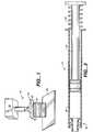
- the system for facilitating hemostasis of the biopsy tractincludes a punch 10 for cutting a pledget 18 of absorbable sponge material from a sheet of this material, an adaptor 12 for delivering the pledget to a biopsy needle 16, and a syringe 14 for hydrating and injecting the pledget.
- the adaptor 12allows a relatively large pledget of absorbable sponge material to be compressed and inserted into the biopsy tract in a hydrated state.
- the absorbable sponge material for use in facilitating hemostasismay be any absorbable sponge which is capable of deforming upon hydration to be delivered by fluid pressure through a biopsy needle or other cannula.
- FIG. 1illustrates one example of a punch 10, also called a dye cutter, for cutting an absorbable sponge sheet 20 into pledgets 18 of an appropriate size for delivery to a biopsy tract.
- the punch 10includes a rectangular blade 22 fixed to a plate 24 having a handle 26.
- the punch 10is pressed down onto a flat sheet 20 of commercially available absorbable sponge to cut the pledget 18 of an appropriate size.
- other cutting devicessuch as, a scissor type hand punch, an automatic punching machine, or a templet and knife may be used for preparation of the pledget 18.
- An alternative pledget forming systemwill be discussed in further detail below with respect to FIGS. 11-13 .
- FIG. 2shows the adaptor 12 according to the present invention in which the pledget 18 is placed for hydration and for delivery through the biopsy needle 16.
- the adaptor 12allows pieces of absorbable sponge material with relatively large cross sections to be easily delivered through a biopsy needle 16 with a much smaller cross section.
- the adaptor 12also functions to remove air from the pledget 18.
- the adaptor 12 which delivers the hydrated pledget 18 to the needle 16includes a first end 30 having an annular lip 32 or female luer fitting for connection to the syringe 14.
- a second end 34 of the adaptor 12has a male luer fitting 36 for connection to a biopsy needle 16 or other cannula.
- the luer fitting 36includes a tapered external surface 38 and a retaining ring 40 with internal threads for receiving an annular lip of the biopsy needle.
- the adaptor 12has an internal lumen with a first diameter D 1 at the first end 30 and a second diameter D 2 at the second end 34. Between the first and second ends of the adaptor 12 a tapered section 42 of the adaptor provides a funnel for compressing the hydrated pledget 18 prior to injection through the biopsy needle 16 and needle hub 28.
- the adaptor 12may be formed in any known manner such as by molding from a plastic material.
- the adaptor 12is transparent so that the pledget 18 can be viewed through the adaptor and the user can visually monitor when the pledget is loaded within the adaptor and when the pledget has been delivered into the needle.
- the adaptor lumenmay be provided with a friction reducing coating for improved delivery. The delivery fluid also reduces friction for improved delivery by wetting the exterior surface of the pledget 18.
- the syringe 14includes a male luer fitting 46, a fluid chamber 48, and a plunger 50.
- the first end 30 of the adaptor 12is connectable to the luer fitting 46 of the conventional syringe 14.
- the syringe 14may be provided with a spring 52 for automatic filling of the syringe 14 with a predetermined volume of fluid.
- the syringemay include a threaded syringe plunger, as shown in FIG. 7 , for accurate injection of small quantities of fluid.
- the syringe volumewill vary depending on the amount of fluid needed for hydration and delivery of the pledget 18 through the biopsy needle 16.
- a biopsy needle 16 for use with the present inventionis preferably a co-axial biopsy needle, such as a bi-axial or a tri-axial biopsy needle.
- a co-axial biopsy needleincludes an outer needle or cannula through which a tissue sample is removed with a tissue scoop or other biopsy instrument. Once the tissue sample has been removed, the outer cannula remains in the patient as illustrated in FIG. 6 .
- the cannula for delivery of the sponge pledgethas been described as a biopsy needle, the cannula may be a catheter, sheath, or any other type of cannula.
- FIG. 4shows the loading and hydration of the pledget 18 within the adaptor 12.
- a pledget 18is cut as described above and placed within the adaptor 12 from the first end 30 of the adaptor.
- the syringe 14is filled with a predetermined amount of fluid, such as saline, and is connected to the first end 30 of the adaptor 12 by the luer fitting 46.
- the plunger 50 of the syringe 14is then depressed slowly causing fluid to pass into the adaptor 12, hydrating the pledget 18, and filling the adaptor with a column of fluid. Care should be taken to inject the fluid slowly to prevent the pledget from being ejected out of the second end 34 of the adaptor.
- the userwaits a few seconds once the fluid is injected into the adaptor 12 until the pledget 18 is adequately hydrated creating a lubricous surface on the pledget.
- the pledget 18may expand within the adaptor to fill or nearly fill the lumen of the adaptor.
- the adaptor 12 with the pledget 18 hydrated within the proximal endis ready to inject the pledget into a biopsy tract to facilitate hemostasis within the biopsy tract.
- the adaptor 12may be loaded prior to beginning the biopsy procedure.
- the outer sheath of the biopsy needle 16 through which the biopsy has been takenis maintained in place within the biopsy tract, as shown in FIG. 6 .
- the biopsy needle 16provides preestablished targeting of the delivery site for delivery of the absorbable sponge pledget 18 and eliminates the uncertainty of re-access.
- the luer fitting 36 of the adaptor 12is connected to the biopsy needle hub 28, as illustrated in FIG. 6 .
- the biopsy needle 16is withdrawn a short distance, such as about 1 to 20 mm, along the biopsy tract to provide space for the pledget 18 to be received in the biopsy tract. Additional fluid is then rapidly injected by the syringe to move the pledget 18 into the biopsy needle 16.
- the adaptor lumenWhen the adaptor lumen has been blocked by the hydrated pledget 18 which has swelled within the adaptor, injection of additional fluid will push the pledget through the tapered section 42 of the adaptor. If the adaptor lumen has not been entirely blocked by the pledget 18, the venturi effect will help draw the pledget through the tapered section 42 of the adaptor.
- the pledget 18After the pledget 18 is moved to the biopsy needle 16, the pledget 18 is then delivered from the needle 16 to the biopsy tract by rapid injection of additional fluid by the syringe 14.
- the hydrated pledget 18quickly expands upon delivery to fill the available space in the biopsy tract to facilitate hemostasis and provide localized compression.
- one example of a needle hub 28has an interior diameter D 3 which is larger than the diameter D 2 at the distal end 36 of the adaptor 12.
- the large internal diameter needle hub 28allows the hydrated pledget 18 which has been compressed by the tapered section 42 of the adaptor to expand in the needle hub before being compressed again into the needle lumen. This compression and enlargement of the hydrated absorbable sponge material, does not adversely effect the pledget delivery and in fact improves the expansion response of some delivered sponge materials as will be discussed in further detail below.
- the needle hub 28may be designed to have a inner diameter approximately the same as the inner diameter D 2 at the distal end 36 of the adaptor.
- the pledget 18should be completely delivered into the biopsy tract by the fluid and only a minimal amount of extraneous fluid should be delivered.
- the pledget 18, once inside the needlemay be delivered with about 0.02 to 1.5 ml of fluid depending on the size of the needle 16 used. Injection of larger amounts of fluid may distend the biopsy tract or displace the pledget within the organ.
- a pledget 18 having a size of approximately 20 mm by 2 mm cut from a sheet of commercially available Gelfoam having a thickness of approximately 1.5 mmcan be hydrated and injected through a standard 18 gauge, approximately 15 cm long biopsy needle with approximately 0.9 ml of fluid.
- An adaptor according to this examplehas a first diameter D 1 of about 0.38 cm, a second diameter D 2 of about 0.14 cm, a total length of about 3.80 cm, and a taper angle of about 45°.
- About 0.3 ml of fluidis injected slowly to hydrate the pledget 18 and fill the adaptor with a column of fluid. Approximately 0.3 ml of fluid is then injected to load the pledget 18 from the adaptor 12 into the biopsy needle 16.
- vent holes 44extend through the side walls of the adaptor 12 adjacent the second end 34 for venting fluid during loading of the pledget 18.
- the userplaces a finger over the second end 34 of the adaptor 12 to prevent the pledget from exiting the adaptor.
- the plunger 50 of the syringe 14is then depressed slowly causing fluid to pass into the adaptor 12 and hydrate the pledget.
- the userwaits a few seconds once the fluid is injected into the adaptor 12 until the pledget 18 is hydrated.
- a removable capmay be used.
- the vent holes 44may be omitted and a screen or a cap having a screen may be used to allow fluid to pass through the screen while the screen prevents the pledget 18 from being ejected.
- a vent capwill be described in further detail below with respect to FIGS. 14 and 15 .
- FIG. 7An alternative embodiment of the delivery system is illustrated in FIG. 7 in which an adaptor 12 is provided with a pressure indicator 64 to monitor pledget injection.
- the pressure indicator 64is removably attached at a luer fitting 66 provided on a side of the adaptor 12.
- the pressure indicator 64includes a pressure dome 68 movable from the convex shaped extended position illustrated in FIG. 7 to a flat position depending on the pressure inside the adaptor 12. Internal pressure within the biopsy needle 16, the adaptor 12, and the syringe 14 will drop as the pledget 18 is extruded from the biopsy needle into the biopsy tract. This causes the pressure dome 68 to move from the convex position illustrated in FIG. 7 to a flat position, indicating that pledget delivery is complete.
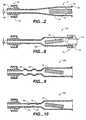
- FIG. 8illustrates an alternative embodiment of an adaptor 12a in which the tapered section 42a is shorter and more abrupt.
- the particular size and shape of the adaptor 12a according to either FIG. 2 or FIG. 8may vary depending on the size of biopsy needle, the tissue sample size, and the size of pledget to be delivered.
- One example of the adaptor 12a of FIG. 8 for delivery of an absorbable sponge pledget 18 through an approximately 18 gauge biopsy needlehas a first adaptor diameter D 1 of about 0.25 cm or greater, preferably about 0.30 to 0.80 cm and a second adaptor diameter D 2 of about 0.25 cm or less, preferably, about 0.05 to 0.23 cm.
- An angle made by a wall of the tapered section 42a with a longitudinal axis of the adaptor 12amay vary from about 5° to 90°, but is preferably between about 30° and 60°.
- the tapered section 42ais illustrated with a substantially planar interior surface, when shown in cross section. However, the tapered section 42a may also have a convex or concave surface in cross section.
- the dimensions described for the adaptor 12aare appropriate for use with an approximately 18 gauge biopsy needle commonly used for liver biopsies. For some of the much larger biopsy needles or cannulas used for skin or breast biopsies the adaptor dimensions would be scaled up accordingly.
- FIG. 8also shows a connector 70 for connecting the adaptor 12 to a syringe 14 when the proximal end of the adaptor is larger in diameter than the standard syringe fitting.
- the connector 70includes a first end 72 for connection to the syringe 14 and a second end 74 for connection to the adaptor 12.
- Gelfoamis a porous, pliable, cross-linked gelatin material and is available commercially in sheet form as pre-compressed or non-compressed sponge.
- the materialmay be provided preformed as a pledget 18 or may be cut with a punch 10, or a stencil or template and knife to form a pledget as described above. Once hydrated, the pledget 18 can be easily compressed to fit into a lumen having a smaller cross sectional area than the original cross sectional area of the pledget.
- the kneading of the hydrated pledget 18 during deliveryencourages air trapped within the Gelfoam to be expelled and replaced with fluid, allowing rapid expansion upon delivery.
- a pledget 18 of a pre-compressed Gelfoamis hydrated and kneaded (expelling air) during delivery
- the pledgetwill have the absorbtion capacity to rapidly expand to many times (e.g., 3 or more times) its original dry volume upon delivery.
- a pledget 18 of the non-compressed Gelfoamis hydrated and kneaded (expelling air) during delivery, the pledget will have the absorbtion capacity to rapidly expand to its original dry volume upon delivery.
- the adaptor 126 of FIG. 9includes two enlarged areas 72 of the lumen. As the absorbable sponge pledget 18 passes through the lumen of the adaptor 12b the material expands and is compressed by the adaptor to increase kneading of the pledget.
- FIG. 10illustrates another alternative embodiment of the adaptor 12c including a lumen with a plurality of staggered irregularities 74 for improved kneading of the absorbable sponge pledget 18.
- the irregularities 74will preferably have a relatively smooth surface to prevent the absorbable sponge material from becoming caught on the irregularities.
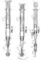
- FIG. 11illustrates an adaptor 112 with a pledget formation template 122 attached to the adaptor.
- the adaptor 112includes a proximal end 130 having a female luer 132 and a distal end 134 having a male luer 136.
- the pledget 118is inserted in the proximal end 130.
- a tapered section 142is provided within the adaptor 112 for compressing the pledget 118 into the biopsy needle.
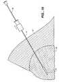
- Some devices and methods which allow the delivery of sponge material with a minimum amount of fluidinclude the use of the pledget configuration illustrated in FIG. 11 , the use of a vent cap for staging of the pledget as illustrated in FIGS. 14 and 15 , and the withdrawal of the biopsy needle during delivery as illustrated in FIG. 16 .
- FIG. 11illustrates a pledget 118 having a proximal cross sectional area which is approximately twice its distal cross sectional area.
- the smaller material mass at the distal end of the pledget 188increases the ease of inserting the pledget into the adaptor 112.
- the smaller distal end of the pledgetalso passes through the delivery cannula or biopsy needle without creating a large back pressure to resist the delivery of the pledget through the cannula.
- the larger proximal section of the pledget 118provides a better seal within the interior of the adaptor 112 and the cannula 16 which allows a minimum amount of fluid to be used to advance the pledget.
- the increased material at the proximal end of the pledget 118also increases the amount of sponge material delivered to the biopsy tract.
- Pledgets 118 with increased cross sectional area proximal endsmay be prepared in a variety of manners.
- the increased proximal masscan be achieved by cutting the pledget with an enlarged proximal end.
- the pledget 118may be formed by folding, rolling, compressing, or otherwise manipulating the sponge material to the desired shape.
- the proximal pledget massmay also be increased by adding separate pieces of material to the proximal end of the pledget. This additional material may be layered, wrapped, coiled or attached to the pledget in any other manner.
- the pledgetsmay also be formed by molding, bump extruding, dipping, or the like.
- the larger cross sectional area proximal endis generally about 1.2 to 4 times the cross sectional area of the distal end.
- the proximal end with the larger cross section areapreferably extends along about 1/8 to 3/4 of the total pledget length.
- the pledget 118 illustrated in FIG. 11has been formed by cutting a strip of material from an absorbable sponge sheet 20 with the aid of the template 122 as illustrated in FIG. 13 . After the strip is cut, the proximal end of the strip is then folded back onto itself to form a pledget 118 with an increased cross sectional area and material mass at a proximal end.
- a Gelfoam pledget for delivery down a 20 gauge biopsy needle or cannulahas a size of approximately 2.54 ⁇ 38.10 ⁇ 1.52 mm (0.1 x 1.5 x 0.06 inches) and is folded as illustrated in FIG. 11 to an overall length of about 22.86 mm (0.9 inches).
- this pledget 118in an adaptor 112 having a largest internal diameter of 3.18 mm (0.125 inches) allows the pledget to be delivered to a 20 gauge or larger biopsy needle.
- Other common biopsy proceduresuse an 18 gauge or larger biopsy needle through a slightly larger guide cannula and would receive a somewhat larger pledget.
- a pledget 118maybe delivered through the cannula to the biopsy site.
- the pledget 118 for use in the system employing an 18 gauge or larger biopsy needlemay be formed from a strip which is approximately 2.79 - 3.05 mm (0.11 - 0.12 inches) wide by about 79.37 mm (3.125 inches) long with a thickness of about 1.52 mm (0.06 inches) and folded to an overall length of about 55.88 mm (2.2 inches).
- This pledget having a single thickness distal end and double thickness proximal endcan be delivered from an adaptor having a largest internal diameter of approximately 3.175 mm (0.125 inches).
- the template 122is a flat plate having recesses 124 along one or more edges of the template.
- the recesses 124have a width and a length which corresponds to a preferred width and length of the pledget.
- the recesses 124form a raised bar 126 at a location where the pledget should be folded.
- a usercuts along the side 128 and end 129 edges of the template 122 with a blade to form a strip of the sponge material which is then folded along the groove or crease formed by the bar 126 to form the pledget 118. It is important to securely hold the sponge sheet by applying downward pressure to the template 122 during cutting to prevent tearing and breaking of the sponge material. Prior to folding the strip of sponge material to form the pledget, the strip may be compressed with a flat surface of the template to compact the sponge and assist in loading the pledget into the adaptor 112.
- the template 122has been illustrated as a plate which is attached to the adaptor 112, it should be understood that the template can also be a separate member.
- the template 122may provide guides for forming pledgets of different sizes for delivery through different sized biopsy needles.
- the template 122may be provided with or without the creasing bar 126 and may be transparent or opaque. In the opaque version, the edges of the recesses 124 are used to align the template with an edge of the sponge sheet 20. In contrast, in a transparent version of the template, the recesses 124 may be eliminated and a visual indication or line may be provided which assists in aligning an edge of the sponge sheet with the template.
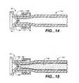
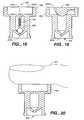
- FIGS. 14 and 15illustrate a preferred vent cap 70 for use with the adapter 112.
- ventsmaybe used to assist in hydrating and staging the pledget within the adapter.
- ventswill allow the pledget to be moved to a preferred axial location within the adapter 112 prior to delivery.
- the ventsallow fluid to be injected and air to be removed from the pledget prior to delivery.
- the vent cap 70 as illustrated in FIG. 14includes a female luer connector 72 including a flange 74 which is received on the male luer 136 of the adapter 112.
- the vent cap 70also includes a conical portion 76 which is configured to extend into a distal end 134 of the adaptor 112.
- the conical portion 76has one or more fluid paths or vent holes 78 which allow air and fluid to exit through the vent cap but prevent the absorbable sponge material of the pledget 118 from passing through the vent cap.
- the vent holemay alternatively be positioned between the vent cap 70 and the adapter 112.
- an exterior of the conical portion 76forms a seal with the lumen of the adaptor 112 at the distal end.
- the diameter of the vent hole 78is approximately 0.13 - 0.51 mm (0.005 - 0.02 inches), preferably approximately 0.25 mm (0.01 inches).
- This small vent hole 78allows the purging and venting of fluid and air from the adapter 112 but does not allow the pledget 118 to pass through the vent hole, even at high pressures such as 34.47 kPa (5 psi) or greater.
- the use of the vent cap 70allows the user to apply high pressures with the syringe used to hydrate the pledget. The high pressures drive the fluid into the pledget causing rapid and thorough hydration of the sponge material. Repeated pulsing of the fluid with the syringe will provide more complete hydration of the pledget.
- the vent cap 70also positions the pledget 118 at a preferred axial position just proximal to the distal end 134 of the adapter 112 as illustrated in FIG. 15 .
- This positioning of the pledget 118 away from the end of the adaptorprevents the pledget from becoming trapped between the adaptor 112 and the biopsy needle hub 28 which is attached to the distal end of the adaptor.
- the sponge materialmay tend to swell out of the distal end of the adapter 112.
- the conical portion 76 of the vent cap 70preferably extends into the adaptor 112 approximately 0.25 to 2.54 mm (0.01 to 0.1 inches), more preferably about 0.25 to 0.76 mm (0.01 to 0.03 inches).
- the portion of the vent cap 70 which extends into the lumen of the adaptor 112can be any desired shape such as dome-shaped, cylindrical, conical or other shape.
- the pledgetmaybe delivered to the biopsy tract by holding the biopsy needle or cannula 16 stationary and injecting the pledget through the biopsy needle. If additional pledgets are to be delivered, the biopsy needle 16 is withdrawn a distance sufficient to accommodate an additional pledget and the additional pledget is then injected.
- the method of delivering the pledget into the biopsy tractmay include withdrawing the biopsy needle or cannula 16 during delivery of the pledget 18 to deliver the pledget in an elongated trail which follows the biopsy tract. Placing the absorbable sponge material in a trail which fills the entire biopsy tract provides the added benefit of providing hemostasis along the entire biopsy tract. This is particularly helpful for stopping the bleeding of biopsy tracts in organs which tend to have excessive bleeding such as the liver, kidney, spleen, and other vascular organs.
- one method of using the system of the present inventioninvolves the delivery of the pledget into the biopsy needle by a predetermined amount of fluid.
- the biopsy needleis then withdrawn at a velocity V while the pledget material is ejected from the biopsy needle at a velocity E with respect to the biopsy needle.
- the velocity V at which the biopsy needle is withdrawnis equal to or less than the velocity E at which the absorbable sponge material is delivered.
- the control of injection of fluid and withdrawal of the needle to achieve the desired trail of absorbable sponge material in the biopsy tractmaybe controlled with an injection controlling device.
- the adaptormaybe used to deliver the pledget into the biopsy needle 16 and then the adaptor is removed from the biopsy needle.
- a plunger or stylet 80which is generally provided with the biopsy needle 16 for inserting the biopsy needle is then used to deliver the pledget from the biopsy needle.
- the biopsy needleextends through the tissue 84 and into the organ 86 for removal of a core of tissue.
- the pledgetis injected into the needle 16 and the plunger 80 is placed within the biopsy needle so that a distal end of the plunger abuts the proximal end of the pledget 118.
- the plunger 80is then held stationary while the biopsy needle 16 is withdrawn from the biopsy site.
- the plunger 80causes the pledget 118 to be delivered in a trail 88 which fills the biopsy tract.
- the trail 88preferably extends along the entire biopsy tract to or past a surface of the organ 86.
- the delivery of the trail 88 of absorbable sponge materialprovides an advantage over the delivery of discrete blobs of material because the trail is able to provide hemostasis along the entire tract.
- a blob of absorbable sponge materialis delivered within the tract at a depth of 1-2 cm from the surface of the organs, this 1-2 cm of biopsy tract may continue to bleed significantly.
- the pledgetmay be delivered as a plug.
- the plunger 80is advanced into the needle 16 pushing the pledget out of the distal end of the needle while the needle is held stationary.
- a combination of delivery of plugs and trailsmay also be used.
- the pledget materialmay be delivered entirely within a single anatomical structure or may cross two or more anatomical structures such as an organ, surrounding tissue and facial layer.
- non-absorbable spongemay also be delivered with the devices, systems, and methods of the present invention.
- a non-absorbable spongemay be desirable where it will be necessary to locate the biopsy site or tract after the procedure.
- the pledget 18has been shown and described as having a rectangular cross section, pledgets of other shapes may also be used.
- the pledgetmay be preformed in any shape, such as with a rectangular or circular cross section or may be rolled from a thin sheet of absorbable sponge material.
- the pledget 18may have a multi-sided cross section, a star shaped cross section, or a folded cross section and may have through or blind holes formed in the dry pledget.
- the pledget size and shapecan be matched to the size and shape of a particular delivery site. Pledget shapes having greater surface area provided by features such as fins provide faster hydration.
- the continuous structure of the absorbable sponge pledget 18provides more secure and reliable placement than a paste or liquid and can even facilitate partial withdrawal, removal, or movement of the delivered pledget.
- the pledgetmay sheer, tear, or otherwise break apart when it is delivered through some small needles leaving the delivered pledget in pieces in the biopsy tract.
- the trail staging chamber 150 as shown in FIG. 17allows the user to visualize the elongated pledget prior to delivery of the pledget into the biopsy needle or other cannula.
- the trail staging chamber 150includes an elongated transparent tube 152 having a proximal fitting 154 for connection to the adaptor 12 and a distal fitting 158 for connection to the biopsy needle 16 or cannula.
- a vent cap 156may also be provided which is connectable to the distal fitting 158.
- a vent cap 156increases the ability to maintain the continuity of the pledget during the delivery of the pledget from the adaptor 12 to the trail staging chamber 150.
- the pledgetis delivered from the adaptor 12 into the trail staging chamber 150 by injection of fluid until a distal end of the pledget contacts the vent cap 156.
- the elongated pledgetis visualized within the staging chamber 150 to determine whether continuity of the pledget has been maintained. If gaps or spaces are viewed, the pledget is discarded by removing the vent cap 156 and expelling the pledget. A new pledget is then injected into the staging chamber 150. Once a continuous pledget has been observed in the staging chamber 150, the staging vent cap 156 is removed, the staging chamber is connected to the biopsy cannula, and the pledget is delivered to the biopsy tract as described above.
- the vent cap 156may have a variety of configurations such as those described above for use with the adaptor. Alternatively, a vent hole may be used in place of the vent cap.
- the vent cap 156helps to maintain the continuity of the pledget during delivery of the pledget from the adaptor 12 to the trail staging chamber 150.
- the vent cap 156is provided with a vent of sufficient size to create back pressure or resistance as the pledget is delivered from the adaptor to the trail staging chamber 150.
- the pledgetdisplaces media which is in front of it. The displaced media escapes through the vent.
- the resistance provided by the ventacts as a damper to the beneficially limit or control an undesirable, sudden advancement of a portion of the pledget from the adaptor 12 to the trail staging chamber 150. Therefore, discontinuities of the pledget are minimized or eliminated.
- vent capsinclude a valve member which has an opened and a closed position. In the closed position, the valve members are designed to provide a back pressure or resistance in the trail staging chamber 150 to the pledget as it is delivered from the adaptor 12. When a certain force is applied against a valve member, the valve member moves from the closed position to the opened position, wherein a gas and/or a fluid may pass through the vent cap.
- vent cap 256has a vent hole 255 and a spring 257 which biases a ball valve 258.
- the vent hole 255extends through the vent cap 256 and includes a sequence of openings.
- the sequence of openingsinclude a proximal opening 255a, a distal opening 255b, and an intermediate opening 255c which is located between the proximal and distal openings.
- the ball valve 258is in a closed position, whereby the spring 257 biases the ball valve to occlude the distal opening 255b.
- a hydrated pledget 118is advanced from the adaptor 12 to the trail staging chamber 150 so that the pledget displaces the gas and/or fluid (i.e., media) which is in front of the pledget.
- This displacement of mediapurges the trail staging chamber 150.
- the ball valvemoves from the closed position to an opened position so that the media can pass through the distal opening 255b.
- the spring biased ball valve 258acts as a one-way valve which allows a gas or a fluid to pass through the vent hole 255.
- the vent cap 356includes a vent hole 355 and a flapper valve 358 which is in a closed position.
- the vent hole 355extends through the vent cap 356 and includes a proximal opening 355a and a distal opening 355b.
- the flapper valve 358acts as a one-way valve which allows a gas or a fluid to pass through the vent hole 355.
- the vent cap 456is substantially similar to the embodiment of FIG. 19 , except that a finger 457 can be used to act as a valve member. When the finger 457 is closed over the vent hole 455, the finger provides a back pressure or resistance in the trail staging chamber 150 to the pledget as it is delivered from the adaptor 12.
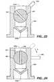
- FIGS. 21 and 22illustrate an alternative embodiment of the vent cap 556 which includes a vent hole 555, a threaded portion 557, and at least one drain hole 558.
- a needle valve 559has a needle extending member 560 and a threaded portion 561 which threadedly engages the threaded portion 557 of the vent cap 556.
- the vent hole 555includes a proximal opening 555a and a distal opening 555b. As shown in FIG. 21 , when the needle valve 559 is in a closed position, the needle extending member 560 extends through the distal opening 555b, thereby occluding that opening and blocking the drain holes 558. By rotating the needle valve 559, the user may change the position of the needle valve.
- the needle valvecan be moved in the direction of arrow A from the closed position of FIG. 21 to the opened position, as shown in FIG. 22 .
- the needle extending member 560does not occlude the distal opening 555b, so that a gas and/or a fluid can pass through the distal opening and through the drain holes 558 to exit the vent cap 556.
- the vent cap 656includes a vent hole 655 which extends through the vent cap.
- the vent hole 655includes a proximal opening 655a and a distal opening 655b.
- a stop cock valve 657has a passage 658 and is connected to a handle 659.
- the stop cock valve 657is rotatably mounted in the vent cap 656 at a position located between the proximal and distal openings 655a, 655b.
- the stop cock valve 657is in a closed position, wherein the stop cock valve is positioned so that the passage 658 is obstructed.
- FIG. 23the stop cock valve 657 is in a closed position, wherein the stop cock valve is positioned so that the passage 658 is obstructed.
- the stop cock valve 657is slidable along the surface of the vent hole 655, and the handle 659 can pivotally rotate the stop cock valve in a direction of arrow B from the closed position of FIG. 23 to an opened position.
- a gas and/or a fluidcan pass through the distal opening 655b and through the passage 658 to exit the vent cap 656.
- the stop cock valve 657forms a seal with the vent cap 656, thereby preventing leakage of gasses or fluids from the adaptor 12 while the stop cock valve is in the closed position.
- valve membermay alternatively comprise any suitable means including, but not limited to, a Touhy-borst valve or other means for controlling or regulating the flow of a gas or fluid from the adaptor 12 to the trail staging chamber 150. It is readily appreciated that any of these embodiments can interface with or be incorporated into the distal end of the trail staging chamber.
- a mechanical interface 758such as a rod, may act as a damper to beneficially limit or control an undesirable sudden advancement of a portion of the pledget.
- the rod 758extends through a vent hole 755 of a vent cap 756 and is slidably movable with respect to the vent cap 756. Further, the rod 758 is designed such that it fits in sliding relation with the elongated transparent tube 752 of the trail staging chamber 750.
- the vent cap 756can couple with the distal end 760 of the trail staging chamber 750.
- the rod 758extends to occupy at least a portion, and preferably an entire length, of the lumen 762 of the elongated transparent tube 752.
- the rod 758may further include a stopping member 764 to position the pledget to a desired distal location within the trail staging chamber 750. It is understood that the stopping member 764 fits in sliding relation with the lumen 762 of the elongated transparent tube 752.
- the stopping member 764may have a roughened surface to facilitate gripping between the stopping member and the lumen 762 of the elongated transparent tube 752.
- the roughened surfaceenhances the friction between the surfaces and may comprise any suitable means including, but not limited to, grooves, ridges, or ribs.
- the rod 758'has a interference fit with the vent cap 756' such that a predetermined axial force is required from the media to move the rod with respect to the vent cap.
- the interference fitcould be adjustable by providing an adjustable compression ring on the vent cap 756' or an adjustable set screw within the cap.
- the stopping means 764"is provided with an interference fit with the lumen 762" of the elongated transparent tube 752".
- a predetermined axial forcesuch as a force applied from the media, is required to move the stopping means 764" and the rod 758" with respect to the elongated transparent tube 752".
- an external axial forceis applied to the rod 858 such as by a spring 860.
- the spring 860couples the vent cap 856 to one end of the rod 858.
- a dashpot mechanismmay be used in place of the spring 860.
- any means of applying external force to the rodwill provide the resistance or dampening to the pledged as it is delivered from the adaptor 12 to the trail staging chamber 150.
- the operator's fingers providing external force to the rodif applied properly, can create the desired back pressure or resistance sought in the above disclosed embodiment.
- a pneumothorax or hemothoraxmay occur when the delivery of the pledget material is discontinuous.
- a pneumothoraxoccurs when air or gas accumulates in the pleural space and a hemothorax occurs when blood accumulates in the pleural space.
- the internal diameter of the transparent tube 152is smaller than the largest internal diameter D 1 of the adaptor and is preferably between the smallest internal diameter D 2 of the adaptor and the internal diameter of the needle or cannula.
- the length of the transparent tube 150may vary depending on the length of the trail of pledget material which is to be delivered.
- trial staging chamber 150is transparent or translucent, it should be appreciated that when the internal diameter of the staging chamber is between D 2 of the adaptor and the internal diameter of the needle, the odds of a continuous trail are improved by use of the trail staging chamber 150 with or without the added benefit of visualization. Thus, an opaque trial staging chamber 150 may also be used.
- the biopsy needle 16is retracted a distance sufficient to provide a space to accommodate an additional pledget 18 and the injection procedure described above is repeated for the additional pledget(s).
- additional pledgets 18may be injected beside an initially injected pledget until the cavity is filled.
- biopsyis most commonly performed by biopsy needle, biopsy may also be performed through other cannulas, such as catheters, long needles, endoscopes, or the like.
- the treatment procedure according to the present inventioncan be used for facilitating hemostasis of puncture wounds through different types of cannulas including needles, catheters, endoscopes, and the like.
- the treatment procedure and systems according to the present inventionmay be used to deliver absorbable or non-absorbable sponge for other therapys.
- spongemay be delivered for cosmetic or reconstructive bulking or for temporary or permanent intravascular embolization.
- the absorbable sponge pledget 18may be used to deliver a beneficial agent, such as contrast agent, thrombin, radiation treatment, or the like.
- the pledgetcan also be used to deliver therapeutic agents, such as radioactive isotopes for localized treatment of tumors, anti-cancer agents, anti-metastatic agents, and the like.
- therapeutic agentssuch as radioactive isotopes for localized treatment of tumors, anti-cancer agents, anti-metastatic agents, and the like.
- anti-cancer agentsinclude 5-fluorouracil, cisplatin, prednisone, and others described in U.S. Patent No. 4,619,913 .
- the absorbable sponge pledget 18may be presoaked with the beneficial agent for delivery to the biopsy tract. Alternatively, the pledget 18 may be hydrated with the beneficial liquid agent or the agent may be delivered to the pledget after the pledget is placed within the biopsy tract.
- a pledget formed of commercially available Gelfoam materialwill be absorbed by the body within 1 to 6 weeks.
- the pledget materialmay be designed to provide different rates of absorption.
- Gelfoamcan be designed to be absorbed at different rates by varying the degree of cross-linking.
- the pledgetis designed to be absorbed in less than one month.
- the treatment of a biopsy tract with a hydrated and injected pledget 18 of absorbable sponge to facilitate hemostasisprovides substantial advantages in comfort over external pressure methods.
- the present inventionalso provides advantages over the insertion of an absorbable sponge material in a dry state with an applicator.
- the adaptor 12allows a relatively large pledget to be compressed and inserted into the biopsy tract in a hydrated state.
- the injected pledget 18conforms in shape quickly to the shape of the biopsy tract and immediately begins blocking blood flow.
- a dry piece of sponge materialmust be cut to the particular size of the biopsy tract and does not swell to fill the tract until the blood has sufficiently saturated the sponge material which can take significantly longer and provides inadequate local compression.
Landscapes
- Health & Medical Sciences (AREA)
- Surgery (AREA)
- Life Sciences & Earth Sciences (AREA)
- Biomedical Technology (AREA)
- Nuclear Medicine, Radiotherapy & Molecular Imaging (AREA)
- Engineering & Computer Science (AREA)
- Cardiology (AREA)
- Heart & Thoracic Surgery (AREA)
- Medical Informatics (AREA)
- Molecular Biology (AREA)
- Animal Behavior & Ethology (AREA)
- General Health & Medical Sciences (AREA)
- Public Health (AREA)
- Veterinary Medicine (AREA)
- Surgical Instruments (AREA)
Abstract
Description
- The invention relates to a wound closure device, and more particularly, the invention relates to a device for facilitating hemostasis of a biopsy tract or other puncture wound by injection of an absorbable sponge.
- Percutaneous needle biopsy of solid organs is one of the most common interventional medical procedures. Millions of percutaneous needle biopsies are performed annually in the United States and throughout the world. Percutaneous biopsy is a safe procedure which has supplanted surgical biopsy for many indications, such as skin biopsy and liver biopsy.
- Possible complications of needle biopsy include bleeding at the biopsy site. The amount of bleeding is related to a number of factors including needle size, tissue sample size, patient's coagulation status, and the location of the biopsy site. Vascular organs such as the liver, a common biopsy target, may bleed significantly after needle biopsy. To minimize bleeding from a biopsy site, small-gauge needles are typically used. Small gauge needles, however, produce less satisfactory biopsy specimens but frequently are favored over larger bored needles because of their perceived safety. In order to minimize the chance of internal bleeding after biopsy, external pressure is applied and patients are often asked to lie in uncomfortable positions, such as the lateral decubitus position, for a number of hours, particularly after liver biopsy.
- Sterile sponges, such as Gelfoam, are prepared in dry sterile sheets which are used as packing material during surgery for control of bleeding. The sponge sheets are left in the surgical site after surgery to stop bleeding and are absorbed by the body in 1 to 6 weeks. A number of techniques have used these absorbable sterile sponge materials to plug a biopsy tract to minimize or prevent bleeding. The absorbable sponge provides a mechanical blockage of the tract, encourages clotting, and minimizes bleeding though the biopsy tract. Despite the advantages of using absorbable sponge to plug a biopsy tract this technique has not achieved widespread use because of difficulty in preparing and delivering the sponge material into the biopsy tract.
- One example of a biopsy wound closure device using an implantable sponge is described in
U. S. Patent No. 5,388,588 . According to this patent, a circular sponge of an absorbable foam material is precut and inserted into a biopsy site by an applicator rod having the sponge positioned on the end. Once the sponge is implanted, the sponge absorbs blood and swells to fill the tract preventing further bleeding at the biopsy site. However, the sponge is difficult to deliver and expands slowly once delivered. In addition, this delivery method can only deliver a sponge of a limited size which provides less local compression than desired and may incompletely fill the target site. Further, bleeding may continue along sections of the biopsy tract where no sponge has been delivered. WO 99/56632 WO 96/22123 - Accordingly, it would be desirable to provide a device and method which will permit the delivery of an absorbable sponge to a biopsy tract in a simple and reliable manner.
- The present invention relates to a device for facilitating hemostasis of a biopsy tract or other puncture wound by injecting an absorbable sponge. The system according to the present invention allows the sponge to be delivered in a hydrated state through the biopsy needle or other cannula directly into the puncture wound.
- In accordance with one aspect of the present invention, a system for injecting a sponge into tissue includes a pledget of sponge having a proximal end with a larger cross sectional area than a distal end, a cannula for delivering the pledget in a hydrated state to the tissue, and an adaptor connectable to the cannula for hydrating and delivering the pledget to the cannula. The adapter has a tapered lumen with a large diameter proximal end and a small diameter distal end. The small diameter distal end is connectable to the cannula.
- It is also disclosed a method of forming a sponge pledget for delivery to tissue includes the steps of cutting a strip of sponge from a sheet of sponge material and folding the strip to form a pledget with a first end having a first cross sectional area and a second folded end which has a second cross sectional area. The second cross sectional area is larger than the first cross sectional area.
- In accordance with a further aspect a system for preparing and delivering a hydrated sponge to a cannula for delivery to tissue includes an adaptor and a template. The adaptor includes an elongated member, a luer connector, and a lumen having a tapered section. The elongated member has a first end, a second end, and a lumen extending from the first end to the second end. The luer connector is provided at the second end of the elongated member for connection to a cannula. The tapered section of the lumen tapers from a first diameter at the first end to a second diameter at the second end which is smaller than the first diameter such that a dry sponge pledget having a width larger than the second diameter is compressible when hydrated to allow passage of the pledget into the second diameter. The template is configured for use in cutting the sponge to a size to be received in the elongated member for delivery to the cannula.
- In accordance with an additional aspect of the invention, an adaptor system for delivering a hydrated sponge to a cannula for delivery to tissue includes an elongated adaptor and a removable vent cap. The elongated adaptor has a distal end, a proximal end, a lumen tapering from a larger diameter at the proximal end to a smaller diameter at the distal end, and a luer connection at the distal end. The removable vent cap is configured to engage the luer connection. The vent cap has a vent hole which is configured to allow fluid to pass out of the adaptor through the vent hole and prevent the sponge from passing through that vent hole.
- In accordance with another aspect of the invention, an adaptor system for delivering a hydrated sponge to a cannula for delivery to tissue includes an elongated adaptor and a removable vent cap. The elongated adaptor has a distal end, a proximal end, a lumen tapering from a larger diameter at the proximal end to a smaller diameter at the distal end, and a luer connection at the distal end. A trail staging member is adapted to extend from the elongated adaptor to the removable vent cap. A rod is also provided which extends through the removable vent cap and into the trail staging member. The rod has a stopping member opposite of the removable vent cap. The stopping member has an interference fit with a lumen extending through the trail staging member, and the stopping member is configured to allow fluid to pass out of the adaptor through the vent cap while preventing the sponge from passing through that vent cap.
- It is also disclosed a method of delivering a sponge into a tissue access tract includes the steps of delivering a hydrated sponge pledget through a cannula positioned in a tissue access tract at a velocity E while withdrawing the cannula from the tissue at a velocity V to deposit the sponge pledget and seal the tissue access tract. The velocity E is greater than or equal to the velocity V.
- In accordance with a further aspect of the invention, a system for preparing and delivering a hydrated sponge to a cannula for delivery to tissue includes an adaptor which comprises an elongated member having a first end, a second end, and a lumen extending from the first end to the second. A fitting is provided at the second end for connection to a cannula whereby a tapered section of the lumen tapers from a first diameter at the first end to a second diameter at the second end which is smaller than the first diameter such that a dry sponge pledget having a width larger than the second diameter is compressible when hydrated to allow passage of the pledget into the second diameter. A transparent visualization chamber is provided which is connectable to the fitting provided at the second end of the elongated member.
- The invention will now be described in greater detail with reference to the preferred embodiments illustrated in the accompanying drawings, in which like elements bear like reference numerals, and wherein:
FIG. 1 is a perspective view of a punch for forming pledgets;FIG. 2 is a side cross sectional view of an adaptor for delivery of a pledget to a needle;FIG. 3 is a side cross sectional view of a syringe for connection to the adaptor;FIG. 4 is a side cross sectional view of an adaptor and syringe combination with a pledget positioned within the adaptor;FIG. 5 is a side cross sectional view of an adaptor and syringe combination in accordance with an alternative embodiment in which the pledget has been hydrated and moved into a small diameter end of the adaptor;FIG. 6 is a side cross sectional view of the loaded adaptor and syringe combination in preparation for connection to a biopsy needle;FIG. 7 is a side cross sectional view of an alternative embodiment of an adaptor connected to a biopsy needle and syringe;FIG. 8 is a side cross sectional view of an alternative embodiment of an adaptor;FIG. 9 is a side cross sectional view of an alternative embodiment of an adaptor with enlargements in the lumen for kneading the pledget;FIG. 10 is a side cross sectional view of an alternative embodiment of an adaptor with irregularities in the lumen for kneading the pledget;FIG. 11 is a side cross sectional view of an adaptor for delivery of a pledget including a template attached to the adaptor;FIG. 12 is a bottom view of the adaptor and template ofFIG. 11 ;FIG. 13 is a top view of the template as it is used for cutting a pledget from an absorbable sponge sheet;FIG. 14 is a side cross sectional view of a distal end of an adaptor with a vent cap attached;FIG. 15 is a side cross sectional view of the adaptor and vent cap ofFIG. 14 having a pledget staged within the adaptor;FIG. 16 is a side cross sectional view of a portion of an organ and a system for delivering a pledget into a biopsy tract in the organ;FIG. 17 is a perspective view of a trail staging device for use with the present invention;FIG. 18 is a side cross sectional view of an alternative embodiment of a vent cap;FIG. 19 is a side cross sectional view of an alternative embodiment of a vent cap;FIG. 20 is a side cross sectional view of an alternative embodiment of a vent cap;FIG. 21 is a side cross sectional view of an alternative embodiment of a vent cap in a closed position;FIG. 22 is a side cross sectional view of the vent cap shownFIG. 21 in an opened position;FIG. 23 is a side cross sectional view of an alternative embodiment of a vent cap in a closed position;FIG. 24 is a side cross sectional view of an alternative embodiment of a vent cap in an opened position;FIG. 25 is an exploded partial cross sectional perspective view of the trail staging device with a rod extending into the trail staging device for use with the present invention;FIG. 26 is a side cross sectional view of an alternative embodiment of a vent cap with the rod extending through the vent cap; andFIG. 27 is a partial side cross sectional view of an alternative embodiment of a vent cap with a rod extending through the vent cap.- The system of the present invention delivers an absorbable sponge material in a hydrated state to facilitate hemostasis of a biopsy tract or other puncture wound in a simple and safe manner. The apparatus for delivering a hydrated absorbable sponge will be described below in connection with treatment of a biopsy tract after a percutaneous needle biopsy. However, the invention may be used for facilitating hemostasis of other types of puncture wounds or tissue access tracts to prevent bleeding of these wounds.
- The system for facilitating hemostasis of the biopsy tract includes a
punch 10 for cutting apledget 18 of absorbable sponge material from a sheet of this material, anadaptor 12 for delivering the pledget to abiopsy needle 16, and asyringe 14 for hydrating and injecting the pledget. Theadaptor 12 allows a relatively large pledget of absorbable sponge material to be compressed and inserted into the biopsy tract in a hydrated state. The absorbable sponge material for use in facilitating hemostasis may be any absorbable sponge which is capable of deforming upon hydration to be delivered by fluid pressure through a biopsy needle or other cannula. - Prior to discussing the present invention in further detail, the following terms are defined:
- "Pledget" means a piece of absorbable sponge of a generally elongated shape having a size which allows injection in a hydrated state through a biopsy needle or other cannula.
- "Sponge" means a biocompatible material which is capable of being hydrated and is resiliently compressible in a hydrated state. Preferably, the sponge is non-immunogenic and may be absorbable or non-absorbable.
- "Absorbable sponge" means sponge which when implanted within a human or other mammalian body is absorbed by the body.
- "Hydrate" means to partially or fully saturate with a fluid, such as, saline, water, contrast agent, thrombin, therapeutic agent, or the like.
- "Kneading" of the absorbable sponge material means both dry and wet manipulation of sponge material which compresses, enlarges, or changes the shape of the sponge material causing the sponge material to have improved expansion response.
FIG. 1 illustrates one example of apunch 10, also called a dye cutter, for cutting anabsorbable sponge sheet 20 intopledgets 18 of an appropriate size for delivery to a biopsy tract. Thepunch 10 includes arectangular blade 22 fixed to aplate 24 having ahandle 26. Thepunch 10 is pressed down onto aflat sheet 20 of commercially available absorbable sponge to cut thepledget 18 of an appropriate size. In addition to thepunch 10 illustrated inFIG. 1 other cutting devices, such as, a scissor type hand punch, an automatic punching machine, or a templet and knife may be used for preparation of thepledget 18. An alternative pledget forming system will be discussed in further detail below with respect toFIGS. 11-13 .FIG. 2 shows theadaptor 12 according to the present invention in which thepledget 18 is placed for hydration and for delivery through thebiopsy needle 16. Theadaptor 12 allows pieces of absorbable sponge material with relatively large cross sections to be easily delivered through abiopsy needle 16 with a much smaller cross section. Theadaptor 12 also functions to remove air from thepledget 18.- The
adaptor 12 which delivers thehydrated pledget 18 to theneedle 16 includes afirst end 30 having anannular lip 32 or female luer fitting for connection to thesyringe 14. Asecond end 34 of theadaptor 12 has a male luer fitting 36 for connection to abiopsy needle 16 or other cannula. The luer fitting 36 includes a taperedexternal surface 38 and a retainingring 40 with internal threads for receiving an annular lip of the biopsy needle. Theadaptor 12 has an internal lumen with a first diameter D1 at thefirst end 30 and a second diameter D2 at thesecond end 34. Between the first and second ends of theadaptor 12 a taperedsection 42 of the adaptor provides a funnel for compressing thehydrated pledget 18 prior to injection through thebiopsy needle 16 andneedle hub 28. - The
adaptor 12 may be formed in any known manner such as by molding from a plastic material. Preferably, theadaptor 12 is transparent so that thepledget 18 can be viewed through the adaptor and the user can visually monitor when the pledget is loaded within the adaptor and when the pledget has been delivered into the needle. The adaptor lumen may be provided with a friction reducing coating for improved delivery. The delivery fluid also reduces friction for improved delivery by wetting the exterior surface of thepledget 18. - The
syringe 14 includes a male luer fitting 46, afluid chamber 48, and aplunger 50. Thefirst end 30 of theadaptor 12 is connectable to the luer fitting 46 of theconventional syringe 14. Thesyringe 14 may be provided with aspring 52 for automatic filling of thesyringe 14 with a predetermined volume of fluid. Alternatively, the syringe may include a threaded syringe plunger, as shown inFIG. 7 , for accurate injection of small quantities of fluid. The syringe volume will vary depending on the amount of fluid needed for hydration and delivery of thepledget 18 through thebiopsy needle 16. - A
biopsy needle 16 for use with the present invention is preferably a co-axial biopsy needle, such as a bi-axial or a tri-axial biopsy needle. A co-axial biopsy needle includes an outer needle or cannula through which a tissue sample is removed with a tissue scoop or other biopsy instrument. Once the tissue sample has been removed, the outer cannula remains in the patient as illustrated inFIG. 6 . Although the cannula for delivery of the sponge pledget has been described as a biopsy needle, the cannula may be a catheter, sheath, or any other type of cannula. - A preferred method of facilitating hemostasis of a biopsy tract will be described with reference to
FIG. 4 which shows the loading and hydration of thepledget 18 within theadaptor 12. Apledget 18 is cut as described above and placed within theadaptor 12 from thefirst end 30 of the adaptor. Thesyringe 14 is filled with a predetermined amount of fluid, such as saline, and is connected to thefirst end 30 of theadaptor 12 by theluer fitting 46. Theplunger 50 of thesyringe 14 is then depressed slowly causing fluid to pass into theadaptor 12, hydrating thepledget 18, and filling the adaptor with a column of fluid. Care should be taken to inject the fluid slowly to prevent the pledget from being ejected out of thesecond end 34 of the adaptor. Preferably, the user waits a few seconds once the fluid is injected into theadaptor 12 until thepledget 18 is adequately hydrated creating a lubricous surface on the pledget. Thepledget 18 may expand within the adaptor to fill or nearly fill the lumen of the adaptor. Theadaptor 12 with thepledget 18 hydrated within the proximal end is ready to inject the pledget into a biopsy tract to facilitate hemostasis within the biopsy tract. Theadaptor 12 may be loaded prior to beginning the biopsy procedure. - After the biopsy procedure has been completed, the outer sheath of the
biopsy needle 16 through which the biopsy has been taken is maintained in place within the biopsy tract, as shown inFIG. 6 . Thebiopsy needle 16 provides preestablished targeting of the delivery site for delivery of theabsorbable sponge pledget 18 and eliminates the uncertainty of re-access. The luer fitting 36 of theadaptor 12 is connected to thebiopsy needle hub 28, as illustrated inFIG. 6 . Thebiopsy needle 16 is withdrawn a short distance, such as about 1 to 20 mm, along the biopsy tract to provide space for thepledget 18 to be received in the biopsy tract. Additional fluid is then rapidly injected by the syringe to move thepledget 18 into thebiopsy needle 16. When the adaptor lumen has been blocked by thehydrated pledget 18 which has swelled within the adaptor, injection of additional fluid will push the pledget through the taperedsection 42 of the adaptor. If the adaptor lumen has not been entirely blocked by thepledget 18, the venturi effect will help draw the pledget through the taperedsection 42 of the adaptor. After thepledget 18 is moved to thebiopsy needle 16, thepledget 18 is then delivered from theneedle 16 to the biopsy tract by rapid injection of additional fluid by thesyringe 14. Thehydrated pledget 18 quickly expands upon delivery to fill the available space in the biopsy tract to facilitate hemostasis and provide localized compression. - As illustrated in the cross sectional view of
FIG. 7 , one example of aneedle hub 28 has an interior diameter D3 which is larger than the diameter D2 at thedistal end 36 of theadaptor 12. The large internaldiameter needle hub 28 allows thehydrated pledget 18 which has been compressed by the taperedsection 42 of the adaptor to expand in the needle hub before being compressed again into the needle lumen. This compression and enlargement of the hydrated absorbable sponge material, does not adversely effect the pledget delivery and in fact improves the expansion response of some delivered sponge materials as will be discussed in further detail below. - A smooth tapered transition between the lumen of the
needle hub 28 and the needle lumen helps to provide for easy injection of thepledget 18. However, needles having internal steps between theneedle hub 28 and theneedle 16 have been used and thepledget 18 is still injected successfully. According to an alternative embodiment of the invention, theneedle hub 28 may be designed to have a inner diameter approximately the same as the inner diameter D2 at thedistal end 36 of the adaptor. - Preferably, specific measured doses of fluid are used to achieve each of the steps of the treatment procedure depending on the pledget size and the dimensions of the
adaptor 12, theneedle 16, and theneedle hub 28. Thepledget 18 should be completely delivered into the biopsy tract by the fluid and only a minimal amount of extraneous fluid should be delivered. For example, thepledget 18, once inside the needle, may be delivered with about 0.02 to 1.5 ml of fluid depending on the size of theneedle 16 used. Injection of larger amounts of fluid may distend the biopsy tract or displace the pledget within the organ. - According to one example, a
pledget 18 having a size of approximately 20 mm by 2 mm cut from a sheet of commercially available Gelfoam having a thickness of approximately 1.5 mm can be hydrated and injected through a standard 18 gauge, approximately 15 cm long biopsy needle with approximately 0.9 ml of fluid. An adaptor according to this example has a first diameter D1 of about 0.38 cm, a second diameter D2 of about 0.14 cm, a total length of about 3.80 cm, and a taper angle of about 45°. About 0.3 ml of fluid is injected slowly to hydrate thepledget 18 and fill the adaptor with a column of fluid. Approximately 0.3 ml of fluid is then injected to load thepledget 18 from theadaptor 12 into thebiopsy needle 16. Finally, about 0.3 ml of fluid is injected to deliver thepledget 18 into the biopsy tract. Loading of the pledget from theadaptor 12 into theneedle 16 and delivery from the needle to the biopsy tract can be combined in one step by delivery of approximately 0.6 ml. Accurate and complete injection of the pledget with a minimum amount of extraneous fluid is achieved by this volumetric injection technique. - According to an alternative embodiment of the adaptor illustrated in
FIG. 5 , vent holes 44 extend through the side walls of theadaptor 12 adjacent thesecond end 34 for venting fluid during loading of thepledget 18. As illustrated inFIG. 5 , the user places a finger over thesecond end 34 of theadaptor 12 to prevent the pledget from exiting the adaptor. Theplunger 50 of thesyringe 14 is then depressed slowly causing fluid to pass into theadaptor 12 and hydrate the pledget. Preferably, the user waits a few seconds once the fluid is injected into theadaptor 12 until thepledget 18 is hydrated. Once thepledget 18 is hydrated, additional fluid is then injected quickly into theadaptor 12 to move thepledget 18 from thefirst end 30 of the adaptor towards thesecond end 34 of the adaptor. As thepledget 18 is compressed by the taperedsection 42 of the adaptor 12 air and fluid are allowed to escape from the adaptor through the vent holes 44. Once thepledget 18 has been moved into the position illustrated inFIG. 5 adjacent thesecond end 34, fluid injection is halted. Theadaptor 12 with thehydrated pledget 18 within the distal end is ready to insert the pledget through a biopsy needle to facilitate hemostasis within the biopsy tract. - As an alternative to placement of a finger at the distal end of the
adaptor 12 during advancement of thepledget 18 through the taperedsection 42, a removable cap may be used. Further, the vent holes 44 may be omitted and a screen or a cap having a screen may be used to allow fluid to pass through the screen while the screen prevents thepledget 18 from being ejected. One example of a vent cap will be described in further detail below with respect toFIGS. 14 and 15 . - An alternative embodiment of the delivery system is illustrated in
FIG. 7 in which anadaptor 12 is provided with apressure indicator 64 to monitor pledget injection. Preferably, thepressure indicator 64 is removably attached at a luer fitting 66 provided on a side of theadaptor 12. Thepressure indicator 64 includes apressure dome 68 movable from the convex shaped extended position illustrated inFIG. 7 to a flat position depending on the pressure inside theadaptor 12. Internal pressure within thebiopsy needle 16, theadaptor 12, and thesyringe 14 will drop as thepledget 18 is extruded from the biopsy needle into the biopsy tract. This causes thepressure dome 68 to move from the convex position illustrated inFIG. 7 to a flat position, indicating that pledget delivery is complete. FIG. 8 illustrates an alternative embodiment of anadaptor 12a in which the taperedsection 42a is shorter and more abrupt. The particular size and shape of theadaptor 12a according to eitherFIG. 2 or FIG. 8 may vary depending on the size of biopsy needle, the tissue sample size, and the size of pledget to be delivered. One example of theadaptor 12a ofFIG. 8 for delivery of anabsorbable sponge pledget 18 through an approximately 18 gauge biopsy needle has a first adaptor diameter D1 of about 0.25 cm or greater, preferably about 0.30 to 0.80 cm and a second adaptor diameter D2 of about 0.25 cm or less, preferably, about 0.05 to 0.23 cm. An angle made by a wall of the taperedsection 42a with a longitudinal axis of theadaptor 12a may vary from about 5° to 90°, but is preferably between about 30° and 60°. The taperedsection 42a is illustrated with a substantially planar interior surface, when shown in cross section. However, the taperedsection 42a may also have a convex or concave surface in cross section. The dimensions described for theadaptor 12a are appropriate for use with an approximately 18 gauge biopsy needle commonly used for liver biopsies. For some of the much larger biopsy needles or cannulas used for skin or breast biopsies the adaptor dimensions would be scaled up accordingly.FIG. 8 also shows aconnector 70 for connecting theadaptor 12 to asyringe 14 when the proximal end of the adaptor is larger in diameter than the standard syringe fitting. Theconnector 70 includes afirst end 72 for connection to thesyringe 14 and asecond end 74 for connection to theadaptor 12.- One type of absorbable sponge material which is acceptable for use in the present invention is Gelfoam, manufactured by the Upjohn Company. Gelfoam is a porous, pliable, cross-linked gelatin material and is available commercially in sheet form as pre-compressed or non-compressed sponge. The material may be provided preformed as a
pledget 18 or may be cut with apunch 10, or a stencil or template and knife to form a pledget as described above. Once hydrated, thepledget 18 can be easily compressed to fit into a lumen having a smaller cross sectional area than the original cross sectional area of the pledget. Additionally, the kneading of thehydrated pledget 18 during delivery encourages air trapped within the Gelfoam to be expelled and replaced with fluid, allowing rapid expansion upon delivery. When apledget 18 of a pre-compressed Gelfoam is hydrated and kneaded (expelling air) during delivery, the pledget will have the absorbtion capacity to rapidly expand to many times (e.g., 3 or more times) its original dry volume upon delivery. When apledget 18 of the non-compressed Gelfoam is hydrated and kneaded (expelling air) during delivery, the pledget will have the absorbtion capacity to rapidly expand to its original dry volume upon delivery. These properties make the Gelfoam sponge material particularly useful for facilitating hemostasis of biopsy sites. - Abrupt lumen diameter changes within or between the
adaptor 12 or theneedle 16 will improve "kneading" of the absorbable sponge material improving hydration of the absorbable sponge material thereby improving the expansion properties of the hydrated delivered absorbable sponge. According to the alternative embodiments of the adaptor illustrated inFIGS. 9 and 10 , enlarged, recessed, or irregular areas in the lumen of the adaptor are provided to impart additional kneading action to the absorbable sponge material further improving expansion properties of the sponge. - The
adaptor 126 ofFIG. 9 includes twoenlarged areas 72 of the lumen. As theabsorbable sponge pledget 18 passes through the lumen of theadaptor 12b the material expands and is compressed by the adaptor to increase kneading of the pledget.FIG. 10 illustrates another alternative embodiment of theadaptor 12c including a lumen with a plurality ofstaggered irregularities 74 for improved kneading of theabsorbable sponge pledget 18. Theirregularities 74 will preferably have a relatively smooth surface to prevent the absorbable sponge material from becoming caught on the irregularities. FIG. 11 illustrates anadaptor 112 with apledget formation template 122 attached to the adaptor. As shown inFIG. 11 , theadaptor 112 includes aproximal end 130 having afemale luer 132 and adistal end 134 having amale luer 136. Thepledget 118 is inserted in theproximal end 130. Atapered section 142 is provided within theadaptor 112 for compressing thepledget 118 into the biopsy needle.- When delivering a
pledget 118 of absorbable sponge material, it is important to deliver a desired amount of the sponge material using a minimum amount of fluid. Some devices and methods which allow the delivery of sponge material with a minimum amount of fluid include the use of the pledget configuration illustrated inFIG. 11 , the use of a vent cap for staging of the pledget as illustrated inFIGS. 14 and 15 , and the withdrawal of the biopsy needle during delivery as illustrated inFIG. 16 . Pledgets 118 having increased proximal cross sectional according to the present invention areas are more easily delivered than pledgets with constant cross sectional areas or decreased proximal cross sectional areas.FIG. 11 illustrates apledget 118 having a proximal cross sectional area which is approximately twice its distal cross sectional area. The smaller material mass at the distal end of the pledget 188 increases the ease of inserting the pledget into theadaptor 112. The smaller distal end of the pledget also passes through the delivery cannula or biopsy needle without creating a large back pressure to resist the delivery of the pledget through the cannula. The larger proximal section of thepledget 118 provides a better seal within the interior of theadaptor 112 and thecannula 16 which allows a minimum amount of fluid to be used to advance the pledget. The increased material at the proximal end of thepledget 118 also increases the amount of sponge material delivered to the biopsy tract.Pledgets 118 with increased cross sectional area proximal ends may be prepared in a variety of manners. For example, if apledget 118 is prepared from a sheet of sponge material, the increased proximal mass can be achieved by cutting the pledget with an enlarged proximal end. Alternatively, thepledget 118 may be formed by folding, rolling, compressing, or otherwise manipulating the sponge material to the desired shape. The proximal pledget mass may also be increased by adding separate pieces of material to the proximal end of the pledget. This additional material may be layered, wrapped, coiled or attached to the pledget in any other manner. The pledgets may also be formed by molding, bump extruding, dipping, or the like. The larger cross sectional area proximal end is generally about 1.2 to 4 times the cross sectional area of the distal end. In addition, the proximal end with the larger cross section area preferably extends along about 1/8 to 3/4 of the total pledget length.- The
pledget 118 illustrated inFIG. 11 has been formed by cutting a strip of material from anabsorbable sponge sheet 20 with the aid of thetemplate 122 as illustrated inFIG. 13 . After the strip is cut, the proximal end of the strip is then folded back onto itself to form apledget 118 with an increased cross sectional area and material mass at a proximal end. One example of a preferred embodiment of a Gelfoam pledget for delivery down a 20 gauge biopsy needle or cannula has a size of approximately 2.54 × 38.10 × 1.52 mm (0.1 x 1.5 x 0.06 inches) and is folded as illustrated inFIG. 11 to an overall length of about 22.86 mm (0.9 inches). Placing thispledget 118 in anadaptor 112 having a largest internal diameter of 3.18 mm (0.125 inches) allows the pledget to be delivered to a 20 gauge or larger biopsy needle. Other common biopsy procedures use an 18 gauge or larger biopsy needle through a slightly larger guide cannula and would receive a somewhat larger pledget. After taking a core sample and removing the biopsy needle from the cannula guide, apledget 118 maybe delivered through the cannula to the biopsy site. Thepledget 118 for use in the system employing an 18 gauge or larger biopsy needle may be formed from a strip which is approximately 2.79 - 3.05 mm (0.11 - 0.12 inches) wide by about 79.37 mm (3.125 inches) long with a thickness of about 1.52 mm (0.06 inches) and folded to an overall length of about 55.88 mm (2.2 inches). This pledget having a single thickness distal end and double thickness proximal end can be delivered from an adaptor having a largest internal diameter of approximately 3.175 mm (0.125 inches). - One method for forming the
pledget 118 with the enlarged proximal end with the aid of atemplate 122 is illustrated inFIG. 13 . Thetemplate 122 is a flatplate having recesses 124 along one or more edges of the template. Therecesses 124 have a width and a length which corresponds to a preferred width and length of the pledget. Therecesses 124 form a raisedbar 126 at a location where the pledget should be folded. When the template is pressed onto asheet 20 of absorbable sponge material, thebar 126 makes an indentation or groove in the sponge material. A user cuts along theside 128 and end 129 edges of thetemplate 122 with a blade to form a strip of the sponge material which is then folded along the groove or crease formed by thebar 126 to form thepledget 118. It is important to securely hold the sponge sheet by applying downward pressure to thetemplate 122 during cutting to prevent tearing and breaking of the sponge material. Prior to folding the strip of sponge material to form the pledget, the strip may be compressed with a flat surface of the template to compact the sponge and assist in loading the pledget into theadaptor 112. - Although the
template 122 has been illustrated as a plate which is attached to theadaptor 112, it should be understood that the template can also be a separate member. In addition, thetemplate 122 may provide guides for forming pledgets of different sizes for delivery through different sized biopsy needles. Thetemplate 122 may be provided with or without the creasingbar 126 and may be transparent or opaque. In the opaque version, the edges of therecesses 124 are used to align the template with an edge of thesponge sheet 20. In contrast, in a transparent version of the template, therecesses 124 may be eliminated and a visual indication or line may be provided which assists in aligning an edge of the sponge sheet with the template. FIGS. 14 and 15 illustrate apreferred vent cap 70 for use with theadapter 112. As discussed above with respect toFIG. 5 , vents maybe used to assist in hydrating and staging the pledget within the adapter. In particular, vents will allow the pledget to be moved to a preferred axial location within theadapter 112 prior to delivery. In addition, the vents allow fluid to be injected and air to be removed from the pledget prior to delivery. Thevent cap 70 as illustrated inFIG. 14 includes afemale luer connector 72 including aflange 74 which is received on themale luer 136 of theadapter 112. Thevent cap 70 also includes aconical portion 76 which is configured to extend into adistal end 134 of theadaptor 112. Theconical portion 76 has one or more fluid paths or ventholes 78 which allow air and fluid to exit through the vent cap but prevent the absorbable sponge material of thepledget 118 from passing through the vent cap. The vent hole may alternatively be positioned between thevent cap 70 and theadapter 112. Preferably, an exterior of theconical portion 76 forms a seal with the lumen of theadaptor 112 at the distal end. The diameter of thevent hole 78 is approximately 0.13 - 0.51 mm (0.005 - 0.02 inches), preferably approximately 0.25 mm (0.01 inches). Thissmall vent hole 78 allows the purging and venting of fluid and air from theadapter 112 but does not allow thepledget 118 to pass through the vent hole, even at high pressures such as 34.47 kPa (5 psi) or greater. The use of thevent cap 70 allows the user to apply high pressures with the syringe used to hydrate the pledget. The high pressures drive the fluid into the pledget causing rapid and thorough hydration of the sponge material. Repeated pulsing of the fluid with the syringe will provide more complete hydration of the pledget.- The
vent cap 70 also positions thepledget 118 at a preferred axial position just proximal to thedistal end 134 of theadapter 112 as illustrated inFIG. 15 . This positioning of thepledget 118 away from the end of the adaptor prevents the pledget from becoming trapped between theadaptor 112 and thebiopsy needle hub 28 which is attached to the distal end of the adaptor. In addition, after hydration of the pledget and removal of thevent cap 70 the sponge material may tend to swell out of the distal end of theadapter 112. Accordingly, theconical portion 76 of thevent cap 70 preferably extends into theadaptor 112 approximately 0.25 to 2.54 mm (0.01 to 0.1 inches), more preferably about 0.25 to 0.76 mm (0.01 to 0.03 inches). - According to the present invention, the portion of the
vent cap 70 which extends into the lumen of theadaptor 112 can be any desired shape such as dome-shaped, cylindrical, conical or other shape. - As described above, the pledget maybe delivered to the biopsy tract by holding the biopsy needle or
cannula 16 stationary and injecting the pledget through the biopsy needle. If additional pledgets are to be delivered, thebiopsy needle 16 is withdrawn a distance sufficient to accommodate an additional pledget and the additional pledget is then injected. - According to an alternative embodiment of the invention, the method of delivering the pledget into the biopsy tract may include withdrawing the biopsy needle or
cannula 16 during delivery of thepledget 18 to deliver the pledget in an elongated trail which follows the biopsy tract. Placing the absorbable sponge material in a trail which fills the entire biopsy tract provides the added benefit of providing hemostasis along the entire biopsy tract. This is particularly helpful for stopping the bleeding of biopsy tracts in organs which tend to have excessive bleeding such as the liver, kidney, spleen, and other vascular organs. - In order to achieve a trail of absorbable sponge material in the biopsy tract, one method of using the system of the present invention involves the delivery of the pledget into the biopsy needle by a predetermined amount of fluid. The biopsy needle is then withdrawn at a velocity V while the pledget material is ejected from the biopsy needle at a velocity E with respect to the biopsy needle. The velocity V at which the biopsy needle is withdrawn is equal to or less than the velocity E at which the absorbable sponge material is delivered. The control of injection of fluid and withdrawal of the needle to achieve the desired trail of absorbable sponge material in the biopsy tract maybe controlled with an injection controlling device.
- According to an alternative embodiment of the invention illustrated in
FIG. 16 , the adaptor maybe used to deliver the pledget into thebiopsy needle 16 and then the adaptor is removed from the biopsy needle. A plunger orstylet 80 which is generally provided with thebiopsy needle 16 for inserting the biopsy needle is then used to deliver the pledget from the biopsy needle. As shown inFIG. 16 , the biopsy needle extends through thetissue 84 and into theorgan 86 for removal of a core of tissue. After biopsy, the pledget is injected into theneedle 16 and theplunger 80 is placed within the biopsy needle so that a distal end of the plunger abuts the proximal end of thepledget 118. Theplunger 80 is then held stationary while thebiopsy needle 16 is withdrawn from the biopsy site. Theplunger 80 causes thepledget 118 to be delivered in atrail 88 which fills the biopsy tract. Thetrail 88 preferably extends along the entire biopsy tract to or past a surface of theorgan 86. The delivery of thetrail 88 of absorbable sponge material provides an advantage over the delivery of discrete blobs of material because the trail is able to provide hemostasis along the entire tract. In contrast, if a blob of absorbable sponge material is delivered within the tract at a depth of 1-2 cm from the surface of the organs, this 1-2 cm of biopsy tract may continue to bleed significantly. - As an alternative to delivery of the pledget as a trail, the pledget may be delivered as a plug. To deliver a plug the
plunger 80 is advanced into theneedle 16 pushing the pledget out of the distal end of the needle while the needle is held stationary. A combination of delivery of plugs and trails may also be used. The pledget material may be delivered entirely within a single anatomical structure or may cross two or more anatomical structures such as an organ, surrounding tissue and facial layer. - Although the invention is primarily intended for delivery of absorbable sponge, non-absorbable sponge may also be delivered with the devices, systems, and methods of the present invention. A non-absorbable sponge may be desirable where it will be necessary to locate the biopsy site or tract after the procedure.
- Although the
pledget 18 has been shown and described as having a rectangular cross section, pledgets of other shapes may also be used. For example, the pledget may be preformed in any shape, such as with a rectangular or circular cross section or may be rolled from a thin sheet of absorbable sponge material. Thepledget 18 may have a multi-sided cross section, a star shaped cross section, or a folded cross section and may have through or blind holes formed in the dry pledget. In addition, the pledget size and shape can be matched to the size and shape of a particular delivery site. Pledget shapes having greater surface area provided by features such as fins provide faster hydration. - The continuous structure of the
absorbable sponge pledget 18 provides more secure and reliable placement than a paste or liquid and can even facilitate partial withdrawal, removal, or movement of the delivered pledget. However, in some cases the pledget may sheer, tear, or otherwise break apart when it is delivered through some small needles leaving the delivered pledget in pieces in the biopsy tract. Thetrail staging chamber 150 as shown inFIG. 17 allows the user to visualize the elongated pledget prior to delivery of the pledget into the biopsy needle or other cannula. - The
trail staging chamber 150 includes an elongatedtransparent tube 152 having aproximal fitting 154 for connection to theadaptor 12 and adistal fitting 158 for connection to thebiopsy needle 16 or cannula. Avent cap 156 may also be provided which is connectable to thedistal fitting 158. Avent cap 156 increases the ability to maintain the continuity of the pledget during the delivery of the pledget from theadaptor 12 to thetrail staging chamber 150. - In use, the pledget is delivered from the
adaptor 12 into thetrail staging chamber 150 by injection of fluid until a distal end of the pledget contacts thevent cap 156. The elongated pledget is visualized within thestaging chamber 150 to determine whether continuity of the pledget has been maintained. If gaps or spaces are viewed, the pledget is discarded by removing thevent cap 156 and expelling the pledget. A new pledget is then injected into thestaging chamber 150. Once a continuous pledget has been observed in thestaging chamber 150, the stagingvent cap 156 is removed, the staging chamber is connected to the biopsy cannula, and the pledget is delivered to the biopsy tract as described above. Thevent cap 156 may have a variety of configurations such as those described above for use with the adaptor. Alternatively, a vent hole may be used in place of the vent cap. - Pledget discontinuities are often the result of uncontrolled advancement of the pledget, which causes a portion of the pledget to tear away or separate from the pledet proximal to it. The
vent cap 156 helps to maintain the continuity of the pledget during delivery of the pledget from theadaptor 12 to thetrail staging chamber 150. In one embodiment, thevent cap 156 is provided with a vent of sufficient size to create back pressure or resistance as the pledget is delivered from the adaptor to thetrail staging chamber 150. As the pledget is delivered to thetrail staging chamber 150, the pledget displaces media which is in front of it. The displaced media escapes through the vent. The resistance provided by the vent acts as a damper to the beneficially limit or control an undesirable, sudden advancement of a portion of the pledget from theadaptor 12 to thetrail staging chamber 150. Therefore, discontinuities of the pledget are minimized or eliminated. - It will also be apparent to one skilled in the art that by using a non-compressible fluid or viscous fluid as the media that it will provide additional dampening benefits to the pledget as it is delivered from the
adaptor 12 to thetrail staging chamber 150. - As shown in
FIGS. 18-24 , alternative embodiments of the vent cap are disclosed. The vent caps include a valve member which has an opened and a closed position. In the closed position, the valve members are designed to provide a back pressure or resistance in thetrail staging chamber 150 to the pledget as it is delivered from theadaptor 12. When a certain force is applied against a valve member, the valve member moves from the closed position to the opened position, wherein a gas and/or a fluid may pass through the vent cap. - For example, in
FIG. 18 , an alternative embodiment of the vent cap is shown wherein thevent cap 256 has avent hole 255 and aspring 257 which biases aball valve 258. Thevent hole 255 extends through thevent cap 256 and includes a sequence of openings. The sequence of openings include aproximal opening 255a, adistal opening 255b, and anintermediate opening 255c which is located between the proximal and distal openings. As shown, theball valve 258 is in a closed position, whereby thespring 257 biases the ball valve to occlude thedistal opening 255b. - In operation, a
hydrated pledget 118 is advanced from theadaptor 12 to thetrail staging chamber 150 so that the pledget displaces the gas and/or fluid (i.e., media) which is in front of the pledget. This displacement of media purges thetrail staging chamber 150. When the media exerts sufficient force against theball valve 258, the ball valve moves from the closed position to an opened position so that the media can pass through thedistal opening 255b. Accordingly, the springbiased ball valve 258 acts as a one-way valve which allows a gas or a fluid to pass through thevent hole 255. - In another embodiment of the vent cap, as shown in
FIG. 19 , thevent cap 356 includes avent hole 355 and aflapper valve 358 which is in a closed position. Thevent hole 355 extends through thevent cap 356 and includes aproximal opening 355a and adistal opening 355b. As in the embodiment ofFIG. 18 , when the pledget displaces the media, the media will exert a force against theflapper valve 358. When the media exerts sufficient force against theflapper valve 358, the flapper valve moves from the closed position to an opened position so that the media can pass through thedistal opening 355b. Accordingly, theflapper valve 358 acts as a one-way valve which allows a gas or a fluid to pass through thevent hole 355. - As shown in
FIG. 20 , in yet another embodiment of the vent cap, thevent cap 456 is substantially similar to the embodiment ofFIG. 19 , except that afinger 457 can be used to act as a valve member. When thefinger 457 is closed over thevent hole 455, the finger provides a back pressure or resistance in thetrail staging chamber 150 to the pledget as it is delivered from theadaptor 12. FIGS. 21 and 22 illustrate an alternative embodiment of thevent cap 556 which includes avent hole 555, a threadedportion 557, and at least onedrain hole 558. Aneedle valve 559 has aneedle extending member 560 and a threadedportion 561 which threadedly engages the threadedportion 557 of thevent cap 556. Thevent hole 555 includes aproximal opening 555a and adistal opening 555b. As shown inFIG. 21 , when theneedle valve 559 is in a closed position, theneedle extending member 560 extends through thedistal opening 555b, thereby occluding that opening and blocking the drain holes 558. By rotating theneedle valve 559, the user may change the position of the needle valve. In particular, the needle valve can be moved in the direction of arrow A from the closed position ofFIG. 21 to the opened position, as shown inFIG. 22 . In the opened position, theneedle extending member 560 does not occlude thedistal opening 555b, so that a gas and/or a fluid can pass through the distal opening and through the drain holes 558 to exit thevent cap 556.- In yet a further embodiment of the vent cap, as shown in
FIGS. 23 and 24 , thevent cap 656 includes a vent hole 655 which extends through the vent cap. The vent hole 655 includes aproximal opening 655a and adistal opening 655b. Astop cock valve 657 has apassage 658 and is connected to ahandle 659. Thestop cock valve 657 is rotatably mounted in thevent cap 656 at a position located between the proximal anddistal openings FIG. 23 , thestop cock valve 657 is in a closed position, wherein the stop cock valve is positioned so that thepassage 658 is obstructed. As shown inFIG. 24 , thestop cock valve 657 is slidable along the surface of the vent hole 655, and thehandle 659 can pivotally rotate the stop cock valve in a direction of arrow B from the closed position ofFIG. 23 to an opened position. When thestop cock valve 657 is in the opened position, a gas and/or a fluid can pass through thedistal opening 655b and through thepassage 658 to exit thevent cap 656. Further, thestop cock valve 657 forms a seal with thevent cap 656, thereby preventing leakage of gasses or fluids from theadaptor 12 while the stop cock valve is in the closed position. - Many types of manual, self-actuated, or adjustable valves are readily apparent to one skilled in the art. The valve member may alternatively comprise any suitable means including, but not limited to, a Touhy-borst valve or other means for controlling or regulating the flow of a gas or fluid from the
adaptor 12 to thetrail staging chamber 150. It is readily appreciated that any of these embodiments can interface with or be incorporated into the distal end of the trail staging chamber. - In an alternative embodiment, as shown in
FIGS. 25 and26 , amechanical interface 758, such as a rod, may act as a damper to beneficially limit or control an undesirable sudden advancement of a portion of the pledget. Therod 758 extends through avent hole 755 of avent cap 756 and is slidably movable with respect to thevent cap 756. Further, therod 758 is designed such that it fits in sliding relation with the elongatedtransparent tube 752 of thetrail staging chamber 750. Thevent cap 756 can couple with thedistal end 760 of thetrail staging chamber 750. Therod 758 extends to occupy at least a portion, and preferably an entire length, of thelumen 762 of the elongatedtransparent tube 752. Therod 758 may further include a stoppingmember 764 to position the pledget to a desired distal location within thetrail staging chamber 750. It is understood that the stoppingmember 764 fits in sliding relation with thelumen 762 of the elongatedtransparent tube 752. The stoppingmember 764 may have a roughened surface to facilitate gripping between the stopping member and thelumen 762 of the elongatedtransparent tube 752. The roughened surface enhances the friction between the surfaces and may comprise any suitable means including, but not limited to, grooves, ridges, or ribs. - In an alternative embodiment, the rod 758' has a interference fit with the vent cap 756' such that a predetermined axial force is required from the media to move the rod with respect to the vent cap. The interference fit could be adjustable by providing an adjustable compression ring on the vent cap 756' or an adjustable set screw within the cap.
- In another embodiment, the stopping means 764" is provided with an interference fit with the
lumen 762" of the elongatedtransparent tube 752". In this configuration, a predetermined axial force, such as a force applied from the media, is required to move the stopping means 764" and therod 758" with respect to the elongatedtransparent tube 752". In this embodiment, it is possible to omit thevent cap 756". - In still another embodiment shown in
FIG. 27 , an external axial force is applied to therod 858 such as by aspring 860. Thespring 860 couples thevent cap 856 to one end of therod 858. Or in another alternative embodiment, a dashpot mechanism may be used in place of thespring 860. - It should be understood by those skilled in the art that any means of applying external force to the rod will provide the resistance or dampening to the pledged as it is delivered from the
adaptor 12 to thetrail staging chamber 150. For example, the operator's fingers providing external force to the rod, if applied properly, can create the desired back pressure or resistance sought in the above disclosed embodiment. - The ability to deliver a continuous trail of the pledget material to a biopsy tract is particularly important in some types of biopsies and is less important in others. For example, when performing a biopsy of the lung a pneumothorax or hemothorax may occur when the delivery of the pledget material is discontinuous. A pneumothorax occurs when air or gas accumulates in the pleural space and a hemothorax occurs when blood accumulates in the pleural space.
- The internal diameter of the
transparent tube 152 is smaller than the largest internal diameter D1 of the adaptor and is preferably between the smallest internal diameter D2 of the adaptor and the internal diameter of the needle or cannula. The length of thetransparent tube 150 may vary depending on the length of the trail of pledget material which is to be delivered. - While the preferred embodiment of the
trial staging chamber 150 is transparent or translucent, it should be appreciated that when the internal diameter of the staging chamber is between D2 of the adaptor and the internal diameter of the needle, the odds of a continuous trail are improved by use of thetrail staging chamber 150 with or without the added benefit of visualization. Thus, an opaquetrial staging chamber 150 may also be used. - In some instances it may be desirable to deliver multiple pledgets in spaced apart positions along the biopsy tract, particularly for a long biopsy tract. For delivery of additional pledgets, the
biopsy needle 16 is retracted a distance sufficient to provide a space to accommodate anadditional pledget 18 and the injection procedure described above is repeated for the additional pledget(s). For a particularly large biopsy site or cavity,additional pledgets 18 may be injected beside an initially injected pledget until the cavity is filled. - Although biopsy is most commonly performed by biopsy needle, biopsy may also be performed through other cannulas, such as catheters, long needles, endoscopes, or the like. The treatment procedure according to the present invention can be used for facilitating hemostasis of puncture wounds through different types of cannulas including needles, catheters, endoscopes, and the like. In addition, the treatment procedure and systems according to the present invention may be used to deliver absorbable or non-absorbable sponge for other therapys. For example, sponge may be delivered for cosmetic or reconstructive bulking or for temporary or permanent intravascular embolization.
- The
absorbable sponge pledget 18 may be used to deliver a beneficial agent, such as contrast agent, thrombin, radiation treatment, or the like. The pledget can also be used to deliver therapeutic agents, such as radioactive isotopes for localized treatment of tumors, anti-cancer agents, anti-metastatic agents, and the like. Examples of anti-cancer agents include 5-fluorouracil, cisplatin, prednisone, and others described inU.S. Patent No. 4,619,913 . Theabsorbable sponge pledget 18 may be presoaked with the beneficial agent for delivery to the biopsy tract. Alternatively, thepledget 18 may be hydrated with the beneficial liquid agent or the agent may be delivered to the pledget after the pledget is placed within the biopsy tract. - A pledget formed of commercially available Gelfoam material will be absorbed by the body within 1 to 6 weeks. However, the pledget material may be designed to provide different rates of absorption. For example, Gelfoam can be designed to be absorbed at different rates by varying the degree of cross-linking. Preferably, the pledget is designed to be absorbed in less than one month.
- The treatment of a biopsy tract with a hydrated and injected
pledget 18 of absorbable sponge to facilitate hemostasis provides substantial advantages in comfort over external pressure methods. In addition, the present invention also provides advantages over the insertion of an absorbable sponge material in a dry state with an applicator. In particular, theadaptor 12 allows a relatively large pledget to be compressed and inserted into the biopsy tract in a hydrated state. The injectedpledget 18 conforms in shape quickly to the shape of the biopsy tract and immediately begins blocking blood flow. In contrast, a dry piece of sponge material must be cut to the particular size of the biopsy tract and does not swell to fill the tract until the blood has sufficiently saturated the sponge material which can take significantly longer and provides inadequate local compression. - While the invention has been described in detail with reference to the preferred embodiments thereof, it will be apparent to one skilled in the art that various changes and modifications can be made and equivalents employed, without departing from the present invention, which is set forth in the appended claims.
Claims (19)
- A system for injecting a sponge into tissue, the system comprising:a pledget (118) of sponge having a first end with a larger cross sectional area than a second end thereof in an uncompressed state;a cannula (16) for delivering the pledget in a hydrated state to the tissue; andan adaptor (112), operably connected to a proximal end of the cannula, for hydrating and delivering the pledget to the cannula, the adaptor having a tapered lumen therein into which the pledget is received and with a proximal end and a distal end, the proximal end having a larger diameter than the distal end, wherein the distal end is operably connected to the cannula,wherein the pledget is received in the lumen of the adaptor such that the first end of the pledget is proximal and the second end is distal.
- The system of Claim 1, wherein the pledget is formed from a sheet of sponge material which is folded to form the larger cross sectional proximal end.
- The system of Claim 1, wherein the pledget proximal end has a cross sectional area of about 1.2 to 4 times a cross sectional area of the distal end.
- The system of Claim 1, wherein the pledget proximal end with the larger cross sectional area extends along 1/8 to 3/4 of total length of the pledget.
- The system of Claim 1, wherein the sponge is an absorbable sponge material.
- The system of claim 1, further comprising a removable vent cap (70,256,356,456,556,656) configured to engage distal end of the adaptor (112), the vent cap having a vent hole which allows fluid to pass out of the adaptor but prevents the sponge from passing through the vent hole.
- The adaptor system of Claim 6, wherein the vent cap is configured to position a distal end of the sponge at a predetermined longitudinal position with respect to the adaptor.
- The adaptor system of Claim 7, wherein the predetermined longitudinal position is proximal of the distal end of the adaptor.
- The system of Claim 6, wherein the vent cap includes a conical portion configured to extend into the distal end of the adaptor.
- The system of Claim 9, wherein the vent hole is provided at a tip of the conical portion.
- The system of claim 1, further comprising: a transparent staging chamber (150,750) connected to the proximal end of the adaptor.
- The system of Claim 11, wherein the staging chamber is an elongated chamber having a constant diameter along its length.
- The system of Claim 11, wherein an interior diameter of the staging chamber is approximately equal to or less than the second diameter of the adapter lumen.
- The system of Claim 1, wherein the adaptor includes a first luer fitting at a distal end for connection to the cannula or the staging chamber and a second luer fitting at a proximal end for connecting the adaptor to a syringe.
- The system of claim 6, wherein the removable vent cap comprises a valve.
- The system of Claim 15, wherein the valve is a spring biased ball valve.
- The system of Claim 15, wherein the valve is a flapper valve.
- The system of Claim 15, wherein the valve is a needle valve.
- The system of Claim 15, wherein the valve is a stop cock valve.
Applications Claiming Priority (7)
| Application Number | Priority Date | Filing Date | Title |
|---|---|---|---|
| US09/247,880US6086607A (en) | 1998-05-01 | 1999-02-10 | Device and method for facilitating hemostasis of a biopsy tract |
| US247880 | 1999-02-10 | ||
| US09/334,700US6200328B1 (en) | 1998-05-01 | 1999-06-16 | Device and method for facilitating hemostasis of a biopsy tract |
| US334700 | 1999-06-16 | ||
| US15940699P | 1999-10-14 | 1999-10-14 | |
| US159406P | 1999-10-14 | ||
| PCT/US2000/003621WO2000047115A1 (en) | 1999-02-10 | 2000-02-10 | Device and method for facilitating hemostasis of a biopsy tract |
Publications (3)
| Publication Number | Publication Date |
|---|---|
| EP1156741A1 EP1156741A1 (en) | 2001-11-28 |
| EP1156741A4 EP1156741A4 (en) | 2009-08-26 |
| EP1156741B1true EP1156741B1 (en) | 2010-12-22 |
Family
ID=27388312
Family Applications (1)
| Application Number | Title | Priority Date | Filing Date |
|---|---|---|---|
| EP00906028AExpired - LifetimeEP1156741B1 (en) | 1999-02-10 | 2000-02-10 | Device for facilitating hemostasis of a biopsy tract |
Country Status (6)
| Country | Link |
|---|---|
| US (2) | US6544236B1 (en) |
| EP (1) | EP1156741B1 (en) |
| JP (1) | JP4271375B2 (en) |
| AU (1) | AU2759500A (en) |
| CA (1) | CA2361564A1 (en) |
| WO (1) | WO2000047115A1 (en) |
Families Citing this family (78)
| Publication number | Priority date | Publication date | Assignee | Title |
|---|---|---|---|---|
| US6162192A (en) | 1998-05-01 | 2000-12-19 | Sub Q, Inc. | System and method for facilitating hemostasis of blood vessel punctures with absorbable sponge |
| US6183497B1 (en)* | 1998-05-01 | 2001-02-06 | Sub-Q, Inc. | Absorbable sponge with contrasting agent |
| US6071300A (en)* | 1995-09-15 | 2000-06-06 | Sub-Q Inc. | Apparatus and method for percutaneous sealing of blood vessel punctures |
| US6315753B1 (en)* | 1998-05-01 | 2001-11-13 | Sub-Q, Inc. | System and method for facilitating hemostasis of blood vessel punctures with absorbable sponge |
| US7625352B1 (en) | 1998-05-01 | 2009-12-01 | Sub-Q, Inc. | Depth and puncture control for system for hemostasis of blood vessel |
| US20010045575A1 (en)* | 1998-05-01 | 2001-11-29 | Mark Ashby | Device and method for facilitating hemostasis of a biopsy tract |
| US6309384B1 (en) | 1999-02-01 | 2001-10-30 | Adiana, Inc. | Method and apparatus for tubal occlusion |
| US6984219B2 (en) | 1999-09-23 | 2006-01-10 | Mark Ashby | Depth and puncture control for blood vessel hemostasis system |
| US6540735B1 (en) | 2000-05-12 | 2003-04-01 | Sub-Q, Inc. | System and method for facilitating hemostasis of blood vessel punctures with absorbable sponge |
| US8187625B2 (en)* | 2001-03-12 | 2012-05-29 | Boston Scientific Scimed, Inc. | Cross-linked gelatin composition comprising a wetting agent |
| WO2002087636A1 (en)* | 2001-03-12 | 2002-11-07 | Sub-Q, Inc. | Methods for sterilizing cross-linked gelatin compositions |
| US6863680B2 (en)* | 2001-11-08 | 2005-03-08 | Sub-Q, Inc. | System and method for delivering hemostasis promoting material to a blood vessel puncture site by fluid pressure |
| US7008440B2 (en)* | 2001-11-08 | 2006-03-07 | Sub-Q, Inc. | System and method for delivering hemostasis promoting material to a blood vessel puncture site by fluid pressure |
| US6746451B2 (en)* | 2001-06-01 | 2004-06-08 | Lance M. Middleton | Tissue cavitation device and method |
| US7037323B2 (en)* | 2001-11-08 | 2006-05-02 | Sub-Q, Inc. | Pledget-handling system and method for delivering hemostasis promoting material to a blood vessel puncture site by fluid pressure |
| US7192436B2 (en)* | 2001-11-08 | 2007-03-20 | Sub-Q, Inc. | Pledget-handling system and method for delivering hemostasis promoting material to a blood vessel puncture site by fluid pressure |
| US7025748B2 (en)* | 2001-11-08 | 2006-04-11 | Boston Scientific Scimed, Inc. | Sheath based blood vessel puncture locator and depth indicator |
| US7455680B1 (en) | 2002-11-04 | 2008-11-25 | Boston Scientific Scimed, Inc. | Apparatus and method for inhibiting blood loss |
| US6790185B1 (en)* | 2002-12-31 | 2004-09-14 | Biopsy Sciences, Llc | Sealant plug delivery methods |
| DE10303573B4 (en)* | 2003-01-30 | 2011-02-24 | Robert Bosch Gmbh | Method, computer program, storage medium and control and / or regulating device for operating an internal combustion engine, and internal combustion engine, in particular for a motor vehicle |
| US7169114B2 (en)* | 2003-06-04 | 2007-01-30 | Krause William R | Biopsy and delivery device |
| US7875043B1 (en) | 2003-12-09 | 2011-01-25 | Sub-Q, Inc. | Cinching loop |
| US20050165487A1 (en) | 2004-01-28 | 2005-07-28 | Muhanna Nabil L. | Artificial intervertebral disc |
| US7959634B2 (en)* | 2004-03-29 | 2011-06-14 | Soteira Inc. | Orthopedic surgery access devices |
| US8425539B2 (en) | 2004-04-12 | 2013-04-23 | Xlumena, Inc. | Luminal structure anchoring devices and methods |
| US12303105B2 (en) | 2004-04-12 | 2025-05-20 | Boston Scientific Scimed, Inc. | Luminal structure anchoring devices and methods |
| US8142462B2 (en) | 2004-05-28 | 2012-03-27 | Cavitech, Llc | Instruments and methods for reducing and stabilizing bone fractures |
| US7632262B2 (en)* | 2004-07-19 | 2009-12-15 | Nexeon Medical Systems, Inc. | Systems and methods for atraumatic implantation of bio-active agents |
| US20080086109A1 (en)* | 2004-11-29 | 2008-04-10 | Paul Shabty | Arterial closure device |
| US20060116635A1 (en)* | 2004-11-29 | 2006-06-01 | Med Enclosure L.L.C. | Arterial closure device |
| US20060229670A1 (en)* | 2005-04-01 | 2006-10-12 | Bates Brian L | Method and a medical closure system for sealing a puncture |
| EP1874180A4 (en)* | 2005-04-29 | 2009-12-16 | Dtherapeutics Llc | Devices, systems and methods for isometric and isotonic contraction of blood vessels using an isovolumic myograph |
| US8992444B2 (en) | 2005-04-29 | 2015-03-31 | Dtherapeutics, Llc | Devices, systems, and methods for determining isometric and isotonic activity of luminal organs |
| DE102005038381A1 (en)* | 2005-08-13 | 2007-02-15 | Amedo Gmbh | Spongy implant |
| US8221363B2 (en) | 2006-10-18 | 2012-07-17 | Baxter Healthcare S.A. | Luer activated device with valve element under tension |
| US7981090B2 (en) | 2006-10-18 | 2011-07-19 | Baxter International Inc. | Luer activated device |
| US7753338B2 (en) | 2006-10-23 | 2010-07-13 | Baxter International Inc. | Luer activated device with minimal fluid displacement |
| US20100063360A1 (en)* | 2006-11-28 | 2010-03-11 | Adiana, Inc. | Side-arm Port Introducer |
| WO2008076330A1 (en) | 2006-12-15 | 2008-06-26 | Soteira, Inc. | Drills and methods for vertebrostenting |
| US20090131952A1 (en) | 2007-05-21 | 2009-05-21 | Brian Schumacher | Delivery system and method for inflatable devices |
| JP5426553B2 (en) | 2007-09-12 | 2014-02-26 | トランスルミナル テクノロジーズ リミテッド ライアビリティー カンパニー | Closure device, placement device, and method of placing a closure device |
| US9456816B2 (en) | 2007-09-12 | 2016-10-04 | Transluminal Technologies, Llc | Closure device, deployment apparatus, and method of deploying a closure device |
| US8876861B2 (en)* | 2007-09-12 | 2014-11-04 | Transluminal Technologies, Inc. | Closure device, deployment apparatus, and method of deploying a closure device |
| US20090204080A1 (en)* | 2008-02-12 | 2009-08-13 | Baxter International Inc. | Two-way valve connector |
| US9364206B2 (en)* | 2008-04-04 | 2016-06-14 | Access Closure, Inc. | Apparatus and methods for sealing a vascular puncture |
| US8029533B2 (en) | 2008-04-04 | 2011-10-04 | Accessclosure, Inc. | Apparatus and methods for sealing a vascular puncture |
| US8454632B2 (en) | 2008-05-12 | 2013-06-04 | Xlumena, Inc. | Tissue anchor for securing tissue layers |
| WO2009155319A1 (en) | 2008-06-17 | 2009-12-23 | Soteira, Inc. | Devices and methods for fracture reduction |
| US9186128B2 (en) | 2008-10-01 | 2015-11-17 | Covidien Lp | Needle biopsy device |
| US8968210B2 (en) | 2008-10-01 | 2015-03-03 | Covidien LLP | Device for needle biopsy with integrated needle protection |
| US9332973B2 (en) | 2008-10-01 | 2016-05-10 | Covidien Lp | Needle biopsy device with exchangeable needle and integrated needle protection |
| US9782565B2 (en) | 2008-10-01 | 2017-10-10 | Covidien Lp | Endoscopic ultrasound-guided biliary access system |
| US11298113B2 (en) | 2008-10-01 | 2022-04-12 | Covidien Lp | Device for needle biopsy with integrated needle protection |
| EP2358280A4 (en)* | 2008-12-19 | 2015-05-06 | Covidien Lp | Method and apparatus for storage and/or introduction of implant for hollow anatomical structure |
| WO2010094032A2 (en) | 2009-02-16 | 2010-08-19 | Aoi Medical Inc. | Trauma nail accumulator |
| WO2010111246A1 (en) | 2009-03-23 | 2010-09-30 | Soteira, Inc. | Devices and methods for vertebrostenting |
| US9364259B2 (en) | 2009-04-21 | 2016-06-14 | Xlumena, Inc. | System and method for delivering expanding trocar through a sheath |
| US9179900B2 (en)* | 2009-12-08 | 2015-11-10 | Phillips Medical Llc | Hemostatic device and its methods of use |
| US9993236B2 (en) | 2009-12-08 | 2018-06-12 | Phillips Medical, LLC | Hemostatic device and its methods of use |
| US20110146692A1 (en)* | 2009-12-23 | 2011-06-23 | Hologic, Inc. | Implant Delivery Device |
| US8231619B2 (en)* | 2010-01-22 | 2012-07-31 | Cytyc Corporation | Sterilization device and method |
| EP2560556B1 (en) | 2010-04-19 | 2016-10-12 | Phillips Medical LLC | A hemostatic device |
| AU2011326525B2 (en) | 2010-11-09 | 2015-06-18 | Transluminal Technologies, Llc | Specially designed magnesium-aluminum alloys and medical uses thereof in a hemodynamic environment |
| GB2499665A (en)* | 2012-02-27 | 2013-08-28 | Exmoor Innovations Ltd | A device for obtaining cell block samples |
| US9320507B2 (en) | 2012-03-26 | 2016-04-26 | Covidien Lp | Cannula valve assembly |
| US9642604B2 (en) | 2012-04-12 | 2017-05-09 | Phillips Medical Llc | Hemostatic system and its methods of use |
| JP6360042B2 (en) | 2012-05-17 | 2018-07-18 | ボストン サイエンティフィック サイムド,インコーポレイテッドBoston Scientific Scimed,Inc. | Method and device for access across adjacent tissue layers |
| US9468428B2 (en) | 2012-06-13 | 2016-10-18 | Phillips Medical Llc | Hemostatic device and its methods of use |
| ES2980140T3 (en) | 2013-02-21 | 2024-09-30 | Boston Scient Scimed Inc | Devices for forming an anastomosis |
| US9724081B2 (en) | 2013-06-04 | 2017-08-08 | Phillips Medical Llc | Hemostatic system and its methods of use |
| US10085730B2 (en) | 2013-07-12 | 2018-10-02 | Phillips Medical, LLC | Hemostatic device and its methods of use |
| US9839416B2 (en) | 2013-07-12 | 2017-12-12 | Phillips Medical, LLC | Hemostatic device and its methods of use |
| US9999437B2 (en)* | 2014-08-27 | 2018-06-19 | Acclarent, Inc. | Method and apparatus for forming opening in a sinus wall |
| ES2686840A1 (en)* | 2017-04-19 | 2018-10-22 | Fundación Para El Fomento De La Investigación Sanitaria Y Biomédica De La Comunitat Valenciana | DURAL SEALING SYSTEM |
| US12232981B2 (en)* | 2019-07-25 | 2025-02-25 | Stryker Corporation | Hydraulic implant introducer |
| EP4225416A4 (en) | 2020-10-08 | 2024-10-16 | Becton, Dickinson and Company | Intravenous catheter device having a probe assembly with an integrated fluid flushing mechanism |
| JP2023545442A (en)* | 2020-10-12 | 2023-10-30 | ベクトン・ディキンソン・アンド・カンパニー | Blood suction syringe with hemolysis prevention function |
| EP4422511A4 (en)* | 2021-10-28 | 2025-07-16 | Joseph Choate Burkett | Device and method for tissue repair at a biopsy site |
Family Cites Families (130)
| Publication number | Priority date | Publication date | Assignee | Title |
|---|---|---|---|---|
| US2899362A (en) | 1959-08-11 | Hemostatic sponges and method of | ||
| US581235A (en) | 1897-04-20 | Island | ||
| US1578517A (en) | 1924-12-23 | 1926-03-30 | George N Hein | Valve piston and barrel construction for hypodermic syringes |
| US2009393A (en)* | 1930-06-12 | 1935-07-30 | Failla Gioacchino | Means for effecting therapeutic implantations |
| US2086580A (en) | 1935-06-24 | 1937-07-13 | Myron C Shirley | Applicator |
| US2465357A (en) | 1944-08-14 | 1949-03-29 | Upjohn Co | Therapeutic sponge and method of making |
| US2492458A (en) | 1944-12-08 | 1949-12-27 | Jr Edgar A Bering | Fibrin foam |
| US2507244A (en) | 1947-04-14 | 1950-05-09 | Upjohn Co | Surgical gelatin dusting powder and process for preparing same |
| CH264752A (en) | 1947-06-03 | 1949-10-31 | Hoffmann La Roche | Process for the manufacture of carriers for pharmaceuticals. |
| US2597011A (en) | 1950-07-28 | 1952-05-20 | Us Agriculture | Preparation of starch sponge |
| US2680442A (en) | 1952-04-04 | 1954-06-08 | Frank L Linzmayer | Disposable suppository casing |
| US2814294A (en) | 1953-04-17 | 1957-11-26 | Becton Dickinson Co | Unit for and method of inhibiting and controlling bleeding tendencies |
| US2824092A (en) | 1955-01-04 | 1958-02-18 | Robert E Thompson | Process of preparation of a gelatincarboxymethyl cellulose complex |
| US2761446A (en) | 1955-03-30 | 1956-09-04 | Chemical Specialties Co Inc | Implanter and cartridge |
| US3157524A (en) | 1960-10-25 | 1964-11-17 | Ethicon Inc | Preparation of collagen sponge |
| US3724465A (en) | 1971-07-22 | 1973-04-03 | Kimberly Clark Co | Tampon coated with insertion aid and method for coating |
| US3874388A (en) | 1973-02-12 | 1975-04-01 | Ochsner Med Found Alton | Shunt defect closure system |
| FR2239233A1 (en)* | 1973-08-03 | 1975-02-28 | Aries Robert | Instrument for inserting pellets into animal body - has chamber with ramp ends joining pellet chamber to needle passage |
| US3990472A (en)* | 1975-07-31 | 1976-11-09 | Northern Illinois Research, Inc. | Check valve |
| US4000741A (en) | 1975-11-03 | 1977-01-04 | The Kendall Company | Syringe assembly |
| SE7608618L (en) | 1976-07-30 | 1978-02-01 | Medline Ab | CLOSURE OF CHANNELS |
| SU782814A1 (en) | 1977-01-18 | 1980-11-30 | За витель | Prosthesis for closing defect in heart tissues |
| US4218155A (en) | 1978-02-10 | 1980-08-19 | Etablissements Armor, S.A. | Stick for applying a liquid |
| US4588395A (en) | 1978-03-10 | 1986-05-13 | Lemelson Jerome H | Catheter and method |
| US4900303A (en)* | 1978-03-10 | 1990-02-13 | Lemelson Jerome H | Dispensing catheter and method |
| US4404970A (en) | 1978-05-19 | 1983-09-20 | Sawyer Philip Nicholas | Hemostatic article and methods for preparing and employing the same |
| US4238480A (en) | 1978-05-19 | 1980-12-09 | Sawyer Philip Nicholas | Method for preparing an improved hemostatic agent and method of employing the same |
| US4211323A (en) | 1978-12-01 | 1980-07-08 | California Medical Developments, Inc. | Disposable diagnostic swab having a stored culture medium |
| US4226236A (en)* | 1979-05-07 | 1980-10-07 | Abbott Laboratories | Prefilled, vented two-compartment syringe |
| US4323072A (en) | 1980-01-18 | 1982-04-06 | Shiley, Incorporated | Cannula for a vein distention system |
| US4340066A (en) | 1980-02-01 | 1982-07-20 | Sherwood Medical Industries Inc. | Medical device for collecting a body sample |
| US4292972A (en) | 1980-07-09 | 1981-10-06 | E. R. Squibb & Sons, Inc. | Lyophilized hydrocolloio foam |
| US4390018A (en) | 1980-09-15 | 1983-06-28 | Zukowski Henry J | Method for preventing loss of spinal fluid after spinal tap |
| NZ205033A (en) | 1982-08-12 | 1986-07-11 | Univ Alabama | Dispensing syringe with longitudinal slits in barrel |
| US4583968A (en)* | 1983-10-03 | 1986-04-22 | Mahurkar Sakharam D | Smooth bore double lumen catheter |
| US4515637A (en) | 1983-11-16 | 1985-05-07 | Seton Company | Collagen-thrombin compositions |
| US4619913A (en) | 1984-05-29 | 1986-10-28 | Matrix Pharmaceuticals, Inc. | Treatments employing drug-containing matrices for introduction into cellular lesion areas |
| US4619261A (en) | 1984-08-09 | 1986-10-28 | Frederico Guerriero | Hydrostatic pressure device for bleeding control through an inflatable, stitchable and retrievable balloon-net system |
| US4587969A (en) | 1985-01-28 | 1986-05-13 | Rolando Gillis | Support assembly for a blood vessel or like organ |
| US4708718A (en) | 1985-07-02 | 1987-11-24 | Target Therapeutics | Hyperthermic treatment of tumors |
| US4998926A (en)* | 1985-12-13 | 1991-03-12 | Becton, Dickinson And Company | Parenteral fluid administration set |
| US4744364A (en) | 1987-02-17 | 1988-05-17 | Intravascular Surgical Instruments, Inc. | Device for sealing percutaneous puncture in a vessel |
| US4890612A (en) | 1987-02-17 | 1990-01-02 | Kensey Nash Corporation | Device for sealing percutaneous puncture in a vessel |
| US4852568A (en) | 1987-02-17 | 1989-08-01 | Kensey Nash Corporation | Method and apparatus for sealing an opening in tissue of a living being |
| EP0292936B1 (en) | 1987-05-26 | 1996-03-06 | Sumitomo Pharmaceuticals Company, Limited | Device for administering solid preparations |
| US4829994A (en) | 1987-05-27 | 1989-05-16 | Kurth Paul A | Femoral compression device for post-catheterization hemostasis |
| US4850960A (en) | 1987-07-08 | 1989-07-25 | Joseph Grayzel | Diagonally tapered, bevelled tip introducing catheter and sheath and method for insertion |
| US4790819A (en) | 1987-08-24 | 1988-12-13 | American Cyanamid Company | Fibrin clot delivery device and method |
| US5195988A (en) | 1988-05-26 | 1993-03-23 | Haaga John R | Medical needle with removable sheath |
| US5080655A (en) | 1988-05-26 | 1992-01-14 | Haaga John R | Medical biopsy needle |
| US4936835A (en) | 1988-05-26 | 1990-06-26 | Haaga John R | Medical needle with bioabsorbable tip |
| US5053046A (en) | 1988-08-22 | 1991-10-01 | Woodrow W. Janese | Dural sealing needle and method of use |
| US4950254A (en)* | 1988-10-14 | 1990-08-21 | Corpak, Inc. | Valve means for enteral therapy administration set |
| US4929246A (en) | 1988-10-27 | 1990-05-29 | C. R. Bard, Inc. | Method for closing and sealing an artery after removing a catheter |
| FR2641692A1 (en) | 1989-01-17 | 1990-07-20 | Nippon Zeon Co | Plug for closing an opening for a medical application, and device for the closure plug making use thereof |
| US5007895A (en) | 1989-04-05 | 1991-04-16 | Burnett George S | Wound packing instrument |
| GB8916781D0 (en) | 1989-07-21 | 1989-09-06 | Nycomed As | Compositions |
| US5061274A (en) | 1989-12-04 | 1991-10-29 | Kensey Nash Corporation | Plug device for sealing openings and method of use |
| US5021059A (en) | 1990-05-07 | 1991-06-04 | Kensey Nash Corporation | Plug device with pulley for sealing punctures in tissue and methods of use |
| US5391183A (en) | 1990-09-21 | 1995-02-21 | Datascope Investment Corp | Device and method sealing puncture wounds |
| ES2030639T1 (en)* | 1990-09-21 | 1992-11-16 | Bioplex Medical B.V. | DEVICE FOR PLACING STYPTIC MATERIAL, IN CONCRETE IN A FIBROUS OR SPONJIFORM FORM ON PERFORATED BLOOD VESSELS, IN CONCRETE ARTERIES. |
| US5108421A (en) | 1990-10-01 | 1992-04-28 | Quinton Instrument Company | Insertion assembly and method of inserting a vessel plug into the body of a patient |
| US5192300A (en) | 1990-10-01 | 1993-03-09 | Quinton Instrument Company | Insertion assembly and method of inserting a vessel plug into the body of a patient |
| US5167624A (en) | 1990-11-09 | 1992-12-01 | Catheter Research, Inc. | Embolus delivery system and method |
| US5366480A (en) | 1990-12-24 | 1994-11-22 | American Cyanamid Company | Synthetic elastomeric buttressing pledget |
| US5221259A (en) | 1990-12-27 | 1993-06-22 | Novoste Corporation | Wound treating device and method of using same |
| US5419765A (en) | 1990-12-27 | 1995-05-30 | Novoste Corporation | Wound treating device and method for treating wounds |
| US5203825A (en)* | 1991-06-07 | 1993-04-20 | Becton, Dickinson And Company | Capillary tube assembly including a vented cap |
| US5310407A (en) | 1991-06-17 | 1994-05-10 | Datascope Investment Corp. | Laparoscopic hemostat delivery system and method for using said system |
| US5282827A (en) | 1991-11-08 | 1994-02-01 | Kensey Nash Corporation | Hemostatic puncture closure system and method of use |
| US5676689A (en) | 1991-11-08 | 1997-10-14 | Kensey Nash Corporation | Hemostatic puncture closure system including vessel location device and method of use |
| US5163904A (en) | 1991-11-12 | 1992-11-17 | Merit Medical Systems, Inc. | Syringe apparatus with attached pressure gauge |
| CA2089999A1 (en) | 1992-02-24 | 1993-08-25 | H. Jonathan Tovey | Resilient arm mesh deployer |
| US5220926A (en) | 1992-07-13 | 1993-06-22 | Jones George T | Finger mounted core biopsy guide |
| US5413571A (en) | 1992-07-16 | 1995-05-09 | Sherwood Medical Company | Device for sealing hemostatic incisions |
| US5284475A (en)* | 1992-07-21 | 1994-02-08 | Mackal Glenn H | Luer valve adapter with expandable end |
| US5443481A (en) | 1992-07-27 | 1995-08-22 | Lee; Benjamin I. | Methods and device for percutaneous sealing of arterial puncture sites |
| CZ281454B6 (en) | 1992-11-23 | 1996-10-16 | Milan Mudr. Csc. Krajíček | Aid for non-surgical closing of a hole in a vessel wall |
| US5417699A (en) | 1992-12-10 | 1995-05-23 | Perclose Incorporated | Device and method for the percutaneous suturing of a vascular puncture site |
| US5334216A (en)* | 1992-12-10 | 1994-08-02 | Howmedica Inc. | Hemostatic plug |
| FI953546L (en) | 1993-01-25 | 1995-09-22 | Sonus Pharma Inc | Phase-transfer colloids as ultrasound contrast agents |
| CA2095553A1 (en) | 1993-02-12 | 1994-08-13 | Kimberly-Clark Worldwide, Inc. | Encapsulated catamenial tampon with and without an applicator |
| US5797960A (en)* | 1993-02-22 | 1998-08-25 | Stevens; John H. | Method and apparatus for thoracoscopic intracardiac procedures |
| US5370656A (en) | 1993-02-26 | 1994-12-06 | Merocel Corporation | Throat pack |
| US5322515A (en) | 1993-03-15 | 1994-06-21 | Abbott Laboratories | Luer adapter assembly for emergency syringe |
| US5388588A (en) | 1993-05-04 | 1995-02-14 | Nabai; Hossein | Biopsy wound closure device and method |
| US5383896A (en) | 1993-05-25 | 1995-01-24 | Gershony; Gary | Vascular sealing device |
| ATE141481T1 (en) | 1993-06-16 | 1996-09-15 | White Spot Ag | DEVICE FOR INTRODUCING FIBRIN GLUE INTO A STITCH CHANNEL |
| US5325857A (en) | 1993-07-09 | 1994-07-05 | Hossein Nabai | Skin biopsy device and method |
| US5486195A (en) | 1993-07-26 | 1996-01-23 | Myers; Gene | Method and apparatus for arteriotomy closure |
| US5462561A (en) | 1993-08-05 | 1995-10-31 | Voda; Jan K. | Suture device |
| US5431639A (en) | 1993-08-12 | 1995-07-11 | Boston Scientific Corporation | Treating wounds caused by medical procedures |
| US5394886A (en)* | 1993-09-20 | 1995-03-07 | Nabai; Hossein | Skin biopsy plug and method |
| US5653730A (en) | 1993-09-28 | 1997-08-05 | Hemodynamics, Inc. | Surface opening adhesive sealer |
| US5383899A (en) | 1993-09-28 | 1995-01-24 | Hammerslag; Julius G. | Method of using a surface opening adhesive sealer |
| US5437292A (en) | 1993-11-19 | 1995-08-01 | Bioseal, Llc | Method for sealing blood vessel puncture sites |
| US5591130A (en)* | 1994-02-22 | 1997-01-07 | Wolfe Troy Medical, Inc. | Esophageal intubation detector with indicator |
| US5649547A (en) | 1994-03-24 | 1997-07-22 | Biopsys Medical, Inc. | Methods and devices for automated biopsy and collection of soft tissue |
| US5526822A (en) | 1994-03-24 | 1996-06-18 | Biopsys Medical, Inc. | Method and apparatus for automated biopsy and collection of soft tissue |
| US5385550A (en) | 1994-03-29 | 1995-01-31 | Su; Chan-Ho | Needle protective means for prevention against stab and virus infection |
| US5545178A (en) | 1994-04-29 | 1996-08-13 | Kensey Nash Corporation | System for closing a percutaneous puncture formed by a trocar to prevent tissue at the puncture from herniating |
| US5522850A (en) | 1994-06-23 | 1996-06-04 | Incontrol, Inc. | Defibrillation and method for cardioverting a heart and storing related activity data |
| US5490736A (en) | 1994-09-08 | 1996-02-13 | Habley Medical Technology Corporation | Stylus applicator for a rehydrated multi-constituent medication |
| US5527332A (en) | 1994-11-02 | 1996-06-18 | Mectra Labs, Inc. | Tissue cutter for surgery |
| US5709704A (en)* | 1994-11-30 | 1998-01-20 | Boston Scientific Corporation | Blood clot filtering |
| US5624402A (en) | 1994-12-12 | 1997-04-29 | Becton, Dickinson And Company | Syringe tip cap |
| WO1996022123A1 (en)* | 1995-01-18 | 1996-07-25 | Medchem Products, Inc. | Apparatus and method for applying a hemostatic agent onto a tissue |
| US5785682A (en)* | 1995-03-22 | 1998-07-28 | Abbott Laboratories | Pre-filled syringe drug delivery system |
| US6183497B1 (en) | 1998-05-01 | 2001-02-06 | Sub-Q, Inc. | Absorbable sponge with contrasting agent |
| US6071300A (en) | 1995-09-15 | 2000-06-06 | Sub-Q Inc. | Apparatus and method for percutaneous sealing of blood vessel punctures |
| US5645566A (en) | 1995-09-15 | 1997-07-08 | Sub Q Inc. | Apparatus and method for percutaneous sealing of blood vessel punctures |
| US6071301A (en) | 1998-05-01 | 2000-06-06 | Sub Q., Inc. | Device and method for facilitating hemostasis of a biopsy tract |
| US6162192A (en) | 1998-05-01 | 2000-12-19 | Sub Q, Inc. | System and method for facilitating hemostasis of blood vessel punctures with absorbable sponge |
| US5616133A (en)* | 1995-10-23 | 1997-04-01 | Cardenas; Juan M. | Syringe for epidural catheter |
| US5769086A (en) | 1995-12-06 | 1998-06-23 | Biopsys Medical, Inc. | Control system and method for automated biopsy device |
| US5800389A (en) | 1996-02-09 | 1998-09-01 | Emx, Inc. | Biopsy device |
| US5893834A (en)* | 1996-04-25 | 1999-04-13 | Sims Portex Inc. | Self-filling blood collection device |
| US5858008A (en) | 1997-04-22 | 1999-01-12 | Becton, Dickinson And Company | Cannula sealing shield assembly |
| US5902310A (en) | 1996-08-12 | 1999-05-11 | Ethicon Endo-Surgery, Inc. | Apparatus and method for marking tissue |
| US5810806A (en) | 1996-08-29 | 1998-09-22 | Ethicon Endo-Surgery | Methods and devices for collection of soft tissue |
| US5681279A (en) | 1996-11-04 | 1997-10-28 | Roper; David H. | Pill dispensing syringe |
| US5782861A (en) | 1996-12-23 | 1998-07-21 | Sub Q Inc. | Percutaneous hemostasis device |
| US6554803B1 (en)* | 1997-04-02 | 2003-04-29 | Arthur Ashman | Combination syringe and aspirator for bone regeneration material and method for using the syringe |
| US6142955A (en)* | 1997-09-19 | 2000-11-07 | United States Surgical Corporation | Biopsy apparatus and method |
| US5868762A (en) | 1997-09-25 | 1999-02-09 | Sub-Q, Inc. | Percutaneous hemostatic suturing device and method |
| US6161034A (en) | 1999-02-02 | 2000-12-12 | Senorx, Inc. | Methods and chemical preparations for time-limited marking of biopsy sites |
| US5997486A (en)* | 1998-04-24 | 1999-12-07 | Denver Biomaterials, Inc. | Device for paracentisis and thoracentisis |
| US6200328B1 (en)* | 1998-05-01 | 2001-03-13 | Sub Q, Incorporated | Device and method for facilitating hemostasis of a biopsy tract |
| US6315753B1 (en) | 1998-05-01 | 2001-11-13 | Sub-Q, Inc. | System and method for facilitating hemostasis of blood vessel punctures with absorbable sponge |
| US20020049405A1 (en)* | 2000-10-19 | 2002-04-25 | Deslauriers Richard J. | Device and method for mixing a two-part composition forming synthetic bone |
- 2000
- 2000-02-10JPJP2000598069Apatent/JP4271375B2/ennot_activeExpired - Fee Related
- 2000-02-10EPEP00906028Apatent/EP1156741B1/ennot_activeExpired - Lifetime
- 2000-02-10WOPCT/US2000/003621patent/WO2000047115A1/enactiveApplication Filing
- 2000-02-10CACA002361564Apatent/CA2361564A1/ennot_activeAbandoned
- 2000-02-10AUAU27595/00Apatent/AU2759500A/ennot_activeAbandoned
- 2000-10-13USUS09/687,590patent/US6544236B1/ennot_activeExpired - Fee Related
- 2003
- 2003-01-29USUS10/354,517patent/US7753872B2/ennot_activeExpired - Fee Related
Also Published As
| Publication number | Publication date |
|---|---|
| EP1156741A4 (en) | 2009-08-26 |
| JP2002536105A (en) | 2002-10-29 |
| US6544236B1 (en) | 2003-04-08 |
| US7753872B2 (en) | 2010-07-13 |
| AU2759500A (en) | 2000-08-29 |
| CA2361564A1 (en) | 2000-08-17 |
| WO2000047115A1 (en) | 2000-08-17 |
| EP1156741A1 (en) | 2001-11-28 |
| US20030135237A1 (en) | 2003-07-17 |
| JP4271375B2 (en) | 2009-06-03 |
Similar Documents
| Publication | Publication Date | Title |
|---|---|---|
| EP1156741B1 (en) | Device for facilitating hemostasis of a biopsy tract | |
| US6200328B1 (en) | Device and method for facilitating hemostasis of a biopsy tract | |
| US6086607A (en) | Device and method for facilitating hemostasis of a biopsy tract | |
| US8050741B2 (en) | Device and method for facilitating hemostasis of a biopsy tract | |
| US6527734B2 (en) | System and method for facilitating hemostasis of blood vessel punctures with absorbable sponge | |
| US6610026B2 (en) | Method of hydrating a sponge material for delivery to a body |
Legal Events
| Date | Code | Title | Description |
|---|---|---|---|
| PUAI | Public reference made under article 153(3) epc to a published international application that has entered the european phase | Free format text:ORIGINAL CODE: 0009012 | |
| 17P | Request for examination filed | Effective date:20010827 | |
| AK | Designated contracting states | Kind code of ref document:A1 Designated state(s):AT BE CH CY DE DK ES FI FR GB GR IE IT LI LU MC NL PT SE | |
| AX | Request for extension of the european patent | Free format text:AL;LT;LV;MK;RO;SI | |
| A4 | Supplementary search report drawn up and despatched | Effective date:20090727 | |
| 17Q | First examination report despatched | Effective date:20091207 | |
| GRAP | Despatch of communication of intention to grant a patent | Free format text:ORIGINAL CODE: EPIDOSNIGR1 | |
| RTI1 | Title (correction) | Free format text:DEVICE FOR FACILITATING HEMOSTASIS OF A BIOPSY TRACT | |
| GRAS | Grant fee paid | Free format text:ORIGINAL CODE: EPIDOSNIGR3 | |
| GRAA | (expected) grant | Free format text:ORIGINAL CODE: 0009210 | |
| AK | Designated contracting states | Kind code of ref document:B1 Designated state(s):AT BE CH CY DE DK ES FI FR GB GR IE IT LI LU MC NL PT SE | |
| REG | Reference to a national code | Ref country code:GB Ref legal event code:FG4D | |
| REG | Reference to a national code | Ref country code:CH Ref legal event code:EP | |
| REG | Reference to a national code | Ref country code:IE Ref legal event code:FG4D | |
| REF | Corresponds to: | Ref document number:60045412 Country of ref document:DE Date of ref document:20110203 Kind code of ref document:P | |
| REG | Reference to a national code | Ref country code:DE Ref legal event code:R096 Ref document number:60045412 Country of ref document:DE Effective date:20110203 | |
| REG | Reference to a national code | Ref country code:NL Ref legal event code:VDEP Effective date:20101222 | |
| PG25 | Lapsed in a contracting state [announced via postgrant information from national office to epo] | Ref country code:FI Free format text:LAPSE BECAUSE OF FAILURE TO SUBMIT A TRANSLATION OF THE DESCRIPTION OR TO PAY THE FEE WITHIN THE PRESCRIBED TIME-LIMIT Effective date:20101222 Ref country code:SE Free format text:LAPSE BECAUSE OF FAILURE TO SUBMIT A TRANSLATION OF THE DESCRIPTION OR TO PAY THE FEE WITHIN THE PRESCRIBED TIME-LIMIT Effective date:20101222 Ref country code:AT Free format text:LAPSE BECAUSE OF FAILURE TO SUBMIT A TRANSLATION OF THE DESCRIPTION OR TO PAY THE FEE WITHIN THE PRESCRIBED TIME-LIMIT Effective date:20101222 Ref country code:CY Free format text:LAPSE BECAUSE OF FAILURE TO SUBMIT A TRANSLATION OF THE DESCRIPTION OR TO PAY THE FEE WITHIN THE PRESCRIBED TIME-LIMIT Effective date:20101222 | |
| PG25 | Lapsed in a contracting state [announced via postgrant information from national office to epo] | Ref country code:GR Free format text:LAPSE BECAUSE OF FAILURE TO SUBMIT A TRANSLATION OF THE DESCRIPTION OR TO PAY THE FEE WITHIN THE PRESCRIBED TIME-LIMIT Effective date:20110323 Ref country code:PT Free format text:LAPSE BECAUSE OF FAILURE TO SUBMIT A TRANSLATION OF THE DESCRIPTION OR TO PAY THE FEE WITHIN THE PRESCRIBED TIME-LIMIT Effective date:20110422 Ref country code:ES Free format text:LAPSE BECAUSE OF FAILURE TO SUBMIT A TRANSLATION OF THE DESCRIPTION OR TO PAY THE FEE WITHIN THE PRESCRIBED TIME-LIMIT Effective date:20110402 Ref country code:BE Free format text:LAPSE BECAUSE OF FAILURE TO SUBMIT A TRANSLATION OF THE DESCRIPTION OR TO PAY THE FEE WITHIN THE PRESCRIBED TIME-LIMIT Effective date:20101222 | |
| PG25 | Lapsed in a contracting state [announced via postgrant information from national office to epo] | Ref country code:NL Free format text:LAPSE BECAUSE OF FAILURE TO SUBMIT A TRANSLATION OF THE DESCRIPTION OR TO PAY THE FEE WITHIN THE PRESCRIBED TIME-LIMIT Effective date:20101222 | |
| PG25 | Lapsed in a contracting state [announced via postgrant information from national office to epo] | Ref country code:MC Free format text:LAPSE BECAUSE OF NON-PAYMENT OF DUE FEES Effective date:20110228 | |
| REG | Reference to a national code | Ref country code:CH Ref legal event code:PL | |
| PLBE | No opposition filed within time limit | Free format text:ORIGINAL CODE: 0009261 | |
| STAA | Information on the status of an ep patent application or granted ep patent | Free format text:STATUS: NO OPPOSITION FILED WITHIN TIME LIMIT | |
| PG25 | Lapsed in a contracting state [announced via postgrant information from national office to epo] | Ref country code:CH Free format text:LAPSE BECAUSE OF NON-PAYMENT OF DUE FEES Effective date:20110228 Ref country code:LI Free format text:LAPSE BECAUSE OF NON-PAYMENT OF DUE FEES Effective date:20110228 Ref country code:DK Free format text:LAPSE BECAUSE OF FAILURE TO SUBMIT A TRANSLATION OF THE DESCRIPTION OR TO PAY THE FEE WITHIN THE PRESCRIBED TIME-LIMIT Effective date:20101222 | |
| REG | Reference to a national code | Ref country code:FR Ref legal event code:ST Effective date:20111102 | |
| GBPC | Gb: european patent ceased through non-payment of renewal fee | Effective date:20110322 | |
| 26N | No opposition filed | Effective date:20110923 | |
| PG25 | Lapsed in a contracting state [announced via postgrant information from national office to epo] | Ref country code:IT Free format text:LAPSE BECAUSE OF FAILURE TO SUBMIT A TRANSLATION OF THE DESCRIPTION OR TO PAY THE FEE WITHIN THE PRESCRIBED TIME-LIMIT Effective date:20101222 | |
| REG | Reference to a national code | Ref country code:DE Ref legal event code:R097 Ref document number:60045412 Country of ref document:DE Effective date:20110923 | |
| PG25 | Lapsed in a contracting state [announced via postgrant information from national office to epo] | Ref country code:FR Free format text:LAPSE BECAUSE OF NON-PAYMENT OF DUE FEES Effective date:20110228 | |
| PG25 | Lapsed in a contracting state [announced via postgrant information from national office to epo] | Ref country code:GB Free format text:LAPSE BECAUSE OF NON-PAYMENT OF DUE FEES Effective date:20110322 | |
| PG25 | Lapsed in a contracting state [announced via postgrant information from national office to epo] | Ref country code:LU Free format text:LAPSE BECAUSE OF NON-PAYMENT OF DUE FEES Effective date:20110210 | |
| PGFP | Annual fee paid to national office [announced via postgrant information from national office to epo] | Ref country code:IE Payment date:20140211 Year of fee payment:15 | |
| PGFP | Annual fee paid to national office [announced via postgrant information from national office to epo] | Ref country code:DE Payment date:20140417 Year of fee payment:15 | |
| REG | Reference to a national code | Ref country code:DE Ref legal event code:R119 Ref document number:60045412 Country of ref document:DE | |
| REG | Reference to a national code | Ref country code:IE Ref legal event code:MM4A | |
| PG25 | Lapsed in a contracting state [announced via postgrant information from national office to epo] | Ref country code:IE Free format text:LAPSE BECAUSE OF NON-PAYMENT OF DUE FEES Effective date:20150210 Ref country code:DE Free format text:LAPSE BECAUSE OF NON-PAYMENT OF DUE FEES Effective date:20150901 |