EP1156593A2 - Code division multiple access (CDMA) communication system - Google Patents
Code division multiple access (CDMA) communication systemDownload PDFInfo
- Publication number
- EP1156593A2 EP1156593A2EP01118805AEP01118805AEP1156593A2EP 1156593 A2EP1156593 A2EP 1156593A2EP 01118805 AEP01118805 AEP 01118805AEP 01118805 AEP01118805 AEP 01118805AEP 1156593 A2EP1156593 A2EP 1156593A2
- Authority
- EP
- European Patent Office
- Prior art keywords
- signal
- code
- message
- channel
- value
- Prior art date
- Legal status (The legal status is an assumption and is not a legal conclusion. Google has not performed a legal analysis and makes no representation as to the accuracy of the status listed.)
- Granted
Links
Images


Classifications
- H—ELECTRICITY
- H04—ELECTRIC COMMUNICATION TECHNIQUE
- H04B—TRANSMISSION
- H04B7/00—Radio transmission systems, i.e. using radiation field
- H04B7/24—Radio transmission systems, i.e. using radiation field for communication between two or more posts
- H04B7/26—Radio transmission systems, i.e. using radiation field for communication between two or more posts at least one of which is mobile
- H04B7/2628—Radio transmission systems, i.e. using radiation field for communication between two or more posts at least one of which is mobile using code-division multiple access [CDMA] or spread spectrum multiple access [SSMA]
- H04B7/2637—Radio transmission systems, i.e. using radiation field for communication between two or more posts at least one of which is mobile using code-division multiple access [CDMA] or spread spectrum multiple access [SSMA] for logical channel control
- G—PHYSICS
- G06—COMPUTING OR CALCULATING; COUNTING
- G06F—ELECTRIC DIGITAL DATA PROCESSING
- G06F13/00—Interconnection of, or transfer of information or other signals between, memories, input/output devices or central processing units
- G06F13/14—Handling requests for interconnection or transfer
- G06F13/36—Handling requests for interconnection or transfer for access to common bus or bus system
- G06F13/368—Handling requests for interconnection or transfer for access to common bus or bus system with decentralised access control
- G06F13/374—Handling requests for interconnection or transfer for access to common bus or bus system with decentralised access control using a self-select method with individual priority code comparator
- H—ELECTRICITY
- H03—ELECTRONIC CIRCUITRY
- H03H—IMPEDANCE NETWORKS, e.g. RESONANT CIRCUITS; RESONATORS
- H03H17/00—Networks using digital techniques
- H03H17/02—Frequency selective networks
- H03H17/0223—Computation saving measures; Accelerating measures
- H03H17/0225—Measures concerning the multipliers
- H03H17/0226—Measures concerning the multipliers comprising look-up tables
- H—ELECTRICITY
- H04—ELECTRIC COMMUNICATION TECHNIQUE
- H04B—TRANSMISSION
- H04B1/00—Details of transmission systems, not covered by a single one of groups H04B3/00 - H04B13/00; Details of transmission systems not characterised by the medium used for transmission
- H04B1/69—Spread spectrum techniques
- H04B1/707—Spread spectrum techniques using direct sequence modulation
- H04B1/7073—Synchronisation aspects
- H04B1/7075—Synchronisation aspects with code phase acquisition
- H04B1/70751—Synchronisation aspects with code phase acquisition using partial detection
- H04B1/70753—Partial phase search
- H—ELECTRICITY
- H04—ELECTRIC COMMUNICATION TECHNIQUE
- H04B—TRANSMISSION
- H04B1/00—Details of transmission systems, not covered by a single one of groups H04B3/00 - H04B13/00; Details of transmission systems not characterised by the medium used for transmission
- H04B1/69—Spread spectrum techniques
- H04B1/707—Spread spectrum techniques using direct sequence modulation
- H04B1/7073—Synchronisation aspects
- H04B1/7075—Synchronisation aspects with code phase acquisition
- H04B1/70754—Setting of search window, i.e. range of code offsets to be searched
- H—ELECTRICITY
- H04—ELECTRIC COMMUNICATION TECHNIQUE
- H04B—TRANSMISSION
- H04B1/00—Details of transmission systems, not covered by a single one of groups H04B3/00 - H04B13/00; Details of transmission systems not characterised by the medium used for transmission
- H04B1/69—Spread spectrum techniques
- H04B1/707—Spread spectrum techniques using direct sequence modulation
- H04B1/7073—Synchronisation aspects
- H04B1/7075—Synchronisation aspects with code phase acquisition
- H04B1/70755—Setting of lock conditions, e.g. threshold
- H—ELECTRICITY
- H04—ELECTRIC COMMUNICATION TECHNIQUE
- H04B—TRANSMISSION
- H04B1/00—Details of transmission systems, not covered by a single one of groups H04B3/00 - H04B13/00; Details of transmission systems not characterised by the medium used for transmission
- H04B1/69—Spread spectrum techniques
- H04B1/707—Spread spectrum techniques using direct sequence modulation
- H04B1/7073—Synchronisation aspects
- H04B1/7075—Synchronisation aspects with code phase acquisition
- H04B1/70758—Multimode search, i.e. using multiple search strategies
- H—ELECTRICITY
- H04—ELECTRIC COMMUNICATION TECHNIQUE
- H04B—TRANSMISSION
- H04B1/00—Details of transmission systems, not covered by a single one of groups H04B3/00 - H04B13/00; Details of transmission systems not characterised by the medium used for transmission
- H04B1/69—Spread spectrum techniques
- H04B1/707—Spread spectrum techniques using direct sequence modulation
- H04B1/7073—Synchronisation aspects
- H04B1/7075—Synchronisation aspects with code phase acquisition
- H04B1/708—Parallel implementation
- H—ELECTRICITY
- H04—ELECTRIC COMMUNICATION TECHNIQUE
- H04B—TRANSMISSION
- H04B1/00—Details of transmission systems, not covered by a single one of groups H04B3/00 - H04B13/00; Details of transmission systems not characterised by the medium used for transmission
- H04B1/69—Spread spectrum techniques
- H04B1/707—Spread spectrum techniques using direct sequence modulation
- H04B1/7073—Synchronisation aspects
- H04B1/7085—Synchronisation aspects using a code tracking loop, e.g. a delay-locked loop
- H—ELECTRICITY
- H04—ELECTRIC COMMUNICATION TECHNIQUE
- H04B—TRANSMISSION
- H04B1/00—Details of transmission systems, not covered by a single one of groups H04B3/00 - H04B13/00; Details of transmission systems not characterised by the medium used for transmission
- H04B1/69—Spread spectrum techniques
- H04B1/707—Spread spectrum techniques using direct sequence modulation
- H04B1/709—Correlator structure
- H04B1/7093—Matched filter type
- H—ELECTRICITY
- H04—ELECTRIC COMMUNICATION TECHNIQUE
- H04B—TRANSMISSION
- H04B1/00—Details of transmission systems, not covered by a single one of groups H04B3/00 - H04B13/00; Details of transmission systems not characterised by the medium used for transmission
- H04B1/69—Spread spectrum techniques
- H04B1/707—Spread spectrum techniques using direct sequence modulation
- H04B1/7097—Interference-related aspects
- H04B1/711—Interference-related aspects the interference being multi-path interference
- H—ELECTRICITY
- H04—ELECTRIC COMMUNICATION TECHNIQUE
- H04B—TRANSMISSION
- H04B7/00—Radio transmission systems, i.e. using radiation field
- H04B7/24—Radio transmission systems, i.e. using radiation field for communication between two or more posts
- H04B7/26—Radio transmission systems, i.e. using radiation field for communication between two or more posts at least one of which is mobile
- H04B7/2628—Radio transmission systems, i.e. using radiation field for communication between two or more posts at least one of which is mobile using code-division multiple access [CDMA] or spread spectrum multiple access [SSMA]
- H—ELECTRICITY
- H04—ELECTRIC COMMUNICATION TECHNIQUE
- H04J—MULTIPLEX COMMUNICATION
- H04J13/00—Code division multiplex systems
- H—ELECTRICITY
- H04—ELECTRIC COMMUNICATION TECHNIQUE
- H04J—MULTIPLEX COMMUNICATION
- H04J13/00—Code division multiplex systems
- H04J13/10—Code generation
- H—ELECTRICITY
- H04—ELECTRIC COMMUNICATION TECHNIQUE
- H04J—MULTIPLEX COMMUNICATION
- H04J13/00—Code division multiplex systems
- H04J13/10—Code generation
- H04J13/102—Combining codes
- H04J13/107—Combining codes by concatenation
- H—ELECTRICITY
- H04—ELECTRIC COMMUNICATION TECHNIQUE
- H04L—TRANSMISSION OF DIGITAL INFORMATION, e.g. TELEGRAPHIC COMMUNICATION
- H04L1/00—Arrangements for detecting or preventing errors in the information received
- H04L1/004—Arrangements for detecting or preventing errors in the information received by using forward error control
- H04L1/0041—Arrangements at the transmitter end
- H04L1/0042—Encoding specially adapted to other signal generation operation, e.g. in order to reduce transmit distortions, jitter, or to improve signal shape
- H—ELECTRICITY
- H04—ELECTRIC COMMUNICATION TECHNIQUE
- H04L—TRANSMISSION OF DIGITAL INFORMATION, e.g. TELEGRAPHIC COMMUNICATION
- H04L1/00—Arrangements for detecting or preventing errors in the information received
- H04L1/004—Arrangements for detecting or preventing errors in the information received by using forward error control
- H04L1/0056—Systems characterized by the type of code used
- H04L1/0059—Convolutional codes
- H—ELECTRICITY
- H04—ELECTRIC COMMUNICATION TECHNIQUE
- H04L—TRANSMISSION OF DIGITAL INFORMATION, e.g. TELEGRAPHIC COMMUNICATION
- H04L25/00—Baseband systems
- H04L25/02—Details ; arrangements for supplying electrical power along data transmission lines
- H04L25/0202—Channel estimation
- H04L25/0212—Channel estimation of impulse response
- H—ELECTRICITY
- H04—ELECTRIC COMMUNICATION TECHNIQUE
- H04L—TRANSMISSION OF DIGITAL INFORMATION, e.g. TELEGRAPHIC COMMUNICATION
- H04L27/00—Modulated-carrier systems
- H04L27/18—Phase-modulated carrier systems, i.e. using phase-shift keying
- H04L27/20—Modulator circuits; Transmitter circuits
- H04L27/2032—Modulator circuits; Transmitter circuits for discrete phase modulation, e.g. in which the phase of the carrier is modulated in a nominally instantaneous manner
- H04L27/2053—Modulator circuits; Transmitter circuits for discrete phase modulation, e.g. in which the phase of the carrier is modulated in a nominally instantaneous manner using more than one carrier, e.g. carriers with different phases
- H04L27/206—Modulator circuits; Transmitter circuits for discrete phase modulation, e.g. in which the phase of the carrier is modulated in a nominally instantaneous manner using more than one carrier, e.g. carriers with different phases using a pair of orthogonal carriers, e.g. quadrature carriers
- H—ELECTRICITY
- H04—ELECTRIC COMMUNICATION TECHNIQUE
- H04L—TRANSMISSION OF DIGITAL INFORMATION, e.g. TELEGRAPHIC COMMUNICATION
- H04L27/00—Modulated-carrier systems
- H04L27/18—Phase-modulated carrier systems, i.e. using phase-shift keying
- H04L27/22—Demodulator circuits; Receiver circuits
- H04L27/233—Demodulator circuits; Receiver circuits using non-coherent demodulation
- H04L27/2332—Demodulator circuits; Receiver circuits using non-coherent demodulation using a non-coherent carrier
- H—ELECTRICITY
- H04—ELECTRIC COMMUNICATION TECHNIQUE
- H04L—TRANSMISSION OF DIGITAL INFORMATION, e.g. TELEGRAPHIC COMMUNICATION
- H04L5/00—Arrangements affording multiple use of the transmission path
- H04L5/14—Two-way operation using the same type of signal, i.e. duplex
- H04L5/1438—Negotiation of transmission parameters prior to communication
- H04L5/1446—Negotiation of transmission parameters prior to communication of transmission speed
- H—ELECTRICITY
- H04—ELECTRIC COMMUNICATION TECHNIQUE
- H04N—PICTORIAL COMMUNICATION, e.g. TELEVISION
- H04N1/00—Scanning, transmission or reproduction of documents or the like, e.g. facsimile transmission; Details thereof
- H04N1/00912—Arrangements for controlling a still picture apparatus or components thereof not otherwise provided for
- H—ELECTRICITY
- H04—ELECTRIC COMMUNICATION TECHNIQUE
- H04N—PICTORIAL COMMUNICATION, e.g. TELEVISION
- H04N1/00—Scanning, transmission or reproduction of documents or the like, e.g. facsimile transmission; Details thereof
- H04N1/32—Circuits or arrangements for control or supervision between transmitter and receiver or between image input and image output device, e.g. between a still-image camera and its memory or between a still-image camera and a printer device
- H04N1/333—Mode signalling or mode changing; Handshaking therefor
- H04N1/3333—Mode signalling or mode changing; Handshaking therefor during transmission, input or output of the picture signal; within a single document or page
- H—ELECTRICITY
- H04—ELECTRIC COMMUNICATION TECHNIQUE
- H04W—WIRELESS COMMUNICATION NETWORKS
- H04W52/00—Power management, e.g. Transmission Power Control [TPC] or power classes
- H04W52/04—Transmission power control [TPC]
- H—ELECTRICITY
- H04—ELECTRIC COMMUNICATION TECHNIQUE
- H04W—WIRELESS COMMUNICATION NETWORKS
- H04W52/00—Power management, e.g. Transmission Power Control [TPC] or power classes
- H04W52/04—Transmission power control [TPC]
- H04W52/06—TPC algorithms
- H04W52/08—Closed loop power control
- H—ELECTRICITY
- H04—ELECTRIC COMMUNICATION TECHNIQUE
- H04W—WIRELESS COMMUNICATION NETWORKS
- H04W52/00—Power management, e.g. Transmission Power Control [TPC] or power classes
- H04W52/04—Transmission power control [TPC]
- H04W52/06—TPC algorithms
- H04W52/14—Separate analysis of uplink or downlink
- H04W52/143—Downlink power control
- H—ELECTRICITY
- H04—ELECTRIC COMMUNICATION TECHNIQUE
- H04W—WIRELESS COMMUNICATION NETWORKS
- H04W52/00—Power management, e.g. Transmission Power Control [TPC] or power classes
- H04W52/04—Transmission power control [TPC]
- H04W52/18—TPC being performed according to specific parameters
- H04W52/24—TPC being performed according to specific parameters using SIR [Signal to Interference Ratio] or other wireless path parameters
- H04W52/241—TPC being performed according to specific parameters using SIR [Signal to Interference Ratio] or other wireless path parameters taking into account channel quality metrics, e.g. SIR, SNR, CIR or Eb/lo
- H—ELECTRICITY
- H04—ELECTRIC COMMUNICATION TECHNIQUE
- H04W—WIRELESS COMMUNICATION NETWORKS
- H04W52/00—Power management, e.g. Transmission Power Control [TPC] or power classes
- H04W52/04—Transmission power control [TPC]
- H04W52/18—TPC being performed according to specific parameters
- H04W52/24—TPC being performed according to specific parameters using SIR [Signal to Interference Ratio] or other wireless path parameters
- H04W52/245—TPC being performed according to specific parameters using SIR [Signal to Interference Ratio] or other wireless path parameters taking into account received signal strength
- H—ELECTRICITY
- H04—ELECTRIC COMMUNICATION TECHNIQUE
- H04W—WIRELESS COMMUNICATION NETWORKS
- H04W52/00—Power management, e.g. Transmission Power Control [TPC] or power classes
- H04W52/04—Transmission power control [TPC]
- H04W52/18—TPC being performed according to specific parameters
- H04W52/26—TPC being performed according to specific parameters using transmission rate or quality of service QoS [Quality of Service]
- H04W52/262—TPC being performed according to specific parameters using transmission rate or quality of service QoS [Quality of Service] taking into account adaptive modulation and coding [AMC] scheme
- H—ELECTRICITY
- H04—ELECTRIC COMMUNICATION TECHNIQUE
- H04W—WIRELESS COMMUNICATION NETWORKS
- H04W52/00—Power management, e.g. Transmission Power Control [TPC] or power classes
- H04W52/04—Transmission power control [TPC]
- H04W52/30—Transmission power control [TPC] using constraints in the total amount of available transmission power
- H04W52/32—TPC of broadcast or control channels
- H04W52/322—Power control of broadcast channels
- H—ELECTRICITY
- H04—ELECTRIC COMMUNICATION TECHNIQUE
- H04W—WIRELESS COMMUNICATION NETWORKS
- H04W52/00—Power management, e.g. Transmission Power Control [TPC] or power classes
- H04W52/04—Transmission power control [TPC]
- H04W52/30—Transmission power control [TPC] using constraints in the total amount of available transmission power
- H04W52/32—TPC of broadcast or control channels
- H04W52/325—Power control of control or pilot channels
- H—ELECTRICITY
- H04—ELECTRIC COMMUNICATION TECHNIQUE
- H04W—WIRELESS COMMUNICATION NETWORKS
- H04W52/00—Power management, e.g. Transmission Power Control [TPC] or power classes
- H04W52/04—Transmission power control [TPC]
- H04W52/30—Transmission power control [TPC] using constraints in the total amount of available transmission power
- H04W52/34—TPC management, i.e. sharing limited amount of power among users or channels or data types, e.g. cell loading
- H04W52/343—TPC management, i.e. sharing limited amount of power among users or channels or data types, e.g. cell loading taking into account loading or congestion level
- H—ELECTRICITY
- H04—ELECTRIC COMMUNICATION TECHNIQUE
- H04W—WIRELESS COMMUNICATION NETWORKS
- H04W52/00—Power management, e.g. Transmission Power Control [TPC] or power classes
- H04W52/04—Transmission power control [TPC]
- H04W52/30—Transmission power control [TPC] using constraints in the total amount of available transmission power
- H04W52/34—TPC management, i.e. sharing limited amount of power among users or channels or data types, e.g. cell loading
- H04W52/346—TPC management, i.e. sharing limited amount of power among users or channels or data types, e.g. cell loading distributing total power among users or channels
- H—ELECTRICITY
- H04—ELECTRIC COMMUNICATION TECHNIQUE
- H04W—WIRELESS COMMUNICATION NETWORKS
- H04W52/00—Power management, e.g. Transmission Power Control [TPC] or power classes
- H04W52/04—Transmission power control [TPC]
- H04W52/30—Transmission power control [TPC] using constraints in the total amount of available transmission power
- H04W52/36—Transmission power control [TPC] using constraints in the total amount of available transmission power with a discrete range or set of values, e.g. step size, ramping or offsets
- H—ELECTRICITY
- H04—ELECTRIC COMMUNICATION TECHNIQUE
- H04W—WIRELESS COMMUNICATION NETWORKS
- H04W52/00—Power management, e.g. Transmission Power Control [TPC] or power classes
- H04W52/04—Transmission power control [TPC]
- H04W52/38—TPC being performed in particular situations
- H04W52/50—TPC being performed in particular situations at the moment of starting communication in a multiple access environment
- H—ELECTRICITY
- H04—ELECTRIC COMMUNICATION TECHNIQUE
- H04W—WIRELESS COMMUNICATION NETWORKS
- H04W52/00—Power management, e.g. Transmission Power Control [TPC] or power classes
- H04W52/04—Transmission power control [TPC]
- H04W52/52—Transmission power control [TPC] using AGC [Automatic Gain Control] circuits or amplifiers
- H—ELECTRICITY
- H04—ELECTRIC COMMUNICATION TECHNIQUE
- H04W—WIRELESS COMMUNICATION NETWORKS
- H04W52/00—Power management, e.g. Transmission Power Control [TPC] or power classes
- H04W52/04—Transmission power control [TPC]
- H04W52/54—Signalisation aspects of the TPC commands, e.g. frame structure
- H—ELECTRICITY
- H03—ELECTRONIC CIRCUITRY
- H03H—IMPEDANCE NETWORKS, e.g. RESONANT CIRCUITS; RESONATORS
- H03H17/00—Networks using digital techniques
- H03H17/02—Frequency selective networks
- H03H17/06—Non-recursive filters
- H—ELECTRICITY
- H04—ELECTRIC COMMUNICATION TECHNIQUE
- H04B—TRANSMISSION
- H04B1/00—Details of transmission systems, not covered by a single one of groups H04B3/00 - H04B13/00; Details of transmission systems not characterised by the medium used for transmission
- H04B1/69—Spread spectrum techniques
- H04B1/707—Spread spectrum techniques using direct sequence modulation
- H04B1/7073—Synchronisation aspects
- H04B1/7075—Synchronisation aspects with code phase acquisition
- H04B1/7077—Multi-step acquisition, e.g. multi-dwell, coarse-fine or validation
- H—ELECTRICITY
- H04—ELECTRIC COMMUNICATION TECHNIQUE
- H04B—TRANSMISSION
- H04B1/00—Details of transmission systems, not covered by a single one of groups H04B3/00 - H04B13/00; Details of transmission systems not characterised by the medium used for transmission
- H04B1/69—Spread spectrum techniques
- H04B1/707—Spread spectrum techniques using direct sequence modulation
- H04B1/7097—Interference-related aspects
- H04B1/711—Interference-related aspects the interference being multi-path interference
- H04B1/7115—Constructive combining of multi-path signals, i.e. RAKE receivers
- H04B1/712—Weighting of fingers for combining, e.g. amplitude control or phase rotation using an inner loop
- H—ELECTRICITY
- H04—ELECTRIC COMMUNICATION TECHNIQUE
- H04B—TRANSMISSION
- H04B2201/00—Indexing scheme relating to details of transmission systems not covered by a single group of H04B3/00 - H04B13/00
- H04B2201/69—Orthogonal indexing scheme relating to spread spectrum techniques in general
- H04B2201/707—Orthogonal indexing scheme relating to spread spectrum techniques in general relating to direct sequence modulation
- H04B2201/70701—Orthogonal indexing scheme relating to spread spectrum techniques in general relating to direct sequence modulation featuring pilot assisted reception
- H—ELECTRICITY
- H04—ELECTRIC COMMUNICATION TECHNIQUE
- H04B—TRANSMISSION
- H04B2201/00—Indexing scheme relating to details of transmission systems not covered by a single group of H04B3/00 - H04B13/00
- H04B2201/69—Orthogonal indexing scheme relating to spread spectrum techniques in general
- H04B2201/707—Orthogonal indexing scheme relating to spread spectrum techniques in general relating to direct sequence modulation
- H04B2201/70702—Intercell-related aspects
- H—ELECTRICITY
- H04—ELECTRIC COMMUNICATION TECHNIQUE
- H04B—TRANSMISSION
- H04B2201/00—Indexing scheme relating to details of transmission systems not covered by a single group of H04B3/00 - H04B13/00
- H04B2201/69—Orthogonal indexing scheme relating to spread spectrum techniques in general
- H04B2201/707—Orthogonal indexing scheme relating to spread spectrum techniques in general relating to direct sequence modulation
- H04B2201/70703—Orthogonal indexing scheme relating to spread spectrum techniques in general relating to direct sequence modulation using multiple or variable rates
- H—ELECTRICITY
- H04—ELECTRIC COMMUNICATION TECHNIQUE
- H04B—TRANSMISSION
- H04B2201/00—Indexing scheme relating to details of transmission systems not covered by a single group of H04B3/00 - H04B13/00
- H04B2201/69—Orthogonal indexing scheme relating to spread spectrum techniques in general
- H04B2201/707—Orthogonal indexing scheme relating to spread spectrum techniques in general relating to direct sequence modulation
- H04B2201/70707—Efficiency-related aspects
- H04B2201/7071—Efficiency-related aspects with dynamic control of receiver resources
- H—ELECTRICITY
- H04—ELECTRIC COMMUNICATION TECHNIQUE
- H04B—TRANSMISSION
- H04B7/00—Radio transmission systems, i.e. using radiation field
- H04B7/24—Radio transmission systems, i.e. using radiation field for communication between two or more posts
- H04B7/26—Radio transmission systems, i.e. using radiation field for communication between two or more posts at least one of which is mobile
- H04B7/2628—Radio transmission systems, i.e. using radiation field for communication between two or more posts at least one of which is mobile using code-division multiple access [CDMA] or spread spectrum multiple access [SSMA]
- H04B7/264—Radio transmission systems, i.e. using radiation field for communication between two or more posts at least one of which is mobile using code-division multiple access [CDMA] or spread spectrum multiple access [SSMA] for data rate control
- H—ELECTRICITY
- H04—ELECTRIC COMMUNICATION TECHNIQUE
- H04J—MULTIPLEX COMMUNICATION
- H04J13/00—Code division multiplex systems
- H04J13/0007—Code type
- H04J13/004—Orthogonal
- H—ELECTRICITY
- H04—ELECTRIC COMMUNICATION TECHNIQUE
- H04J—MULTIPLEX COMMUNICATION
- H04J13/00—Code division multiplex systems
- H04J13/0007—Code type
- H04J13/004—Orthogonal
- H04J13/0048—Walsh
- H—ELECTRICITY
- H04—ELECTRIC COMMUNICATION TECHNIQUE
- H04J—MULTIPLEX COMMUNICATION
- H04J13/00—Code division multiplex systems
- H04J13/0077—Multicode, e.g. multiple codes assigned to one user
- H—ELECTRICITY
- H04—ELECTRIC COMMUNICATION TECHNIQUE
- H04J—MULTIPLEX COMMUNICATION
- H04J13/00—Code division multiplex systems
- H04J13/10—Code generation
- H04J13/12—Generation of orthogonal codes
- H—ELECTRICITY
- H04—ELECTRIC COMMUNICATION TECHNIQUE
- H04J—MULTIPLEX COMMUNICATION
- H04J13/00—Code division multiplex systems
- H04J13/16—Code allocation
- H—ELECTRICITY
- H04—ELECTRIC COMMUNICATION TECHNIQUE
- H04J—MULTIPLEX COMMUNICATION
- H04J13/00—Code division multiplex systems
- H04J13/0007—Code type
- H04J2013/0037—Multilevel codes
- H—ELECTRICITY
- H04—ELECTRIC COMMUNICATION TECHNIQUE
- H04L—TRANSMISSION OF DIGITAL INFORMATION, e.g. TELEGRAPHIC COMMUNICATION
- H04L1/00—Arrangements for detecting or preventing errors in the information received
- H04L1/0001—Systems modifying transmission characteristics according to link quality, e.g. power backoff
- H—ELECTRICITY
- H04—ELECTRIC COMMUNICATION TECHNIQUE
- H04L—TRANSMISSION OF DIGITAL INFORMATION, e.g. TELEGRAPHIC COMMUNICATION
- H04L1/00—Arrangements for detecting or preventing errors in the information received
- H04L1/004—Arrangements for detecting or preventing errors in the information received by using forward error control
- H04L1/0045—Arrangements at the receiver end
- H04L1/0047—Decoding adapted to other signal detection operation
- H—ELECTRICITY
- H04—ELECTRIC COMMUNICATION TECHNIQUE
- H04L—TRANSMISSION OF DIGITAL INFORMATION, e.g. TELEGRAPHIC COMMUNICATION
- H04L1/00—Arrangements for detecting or preventing errors in the information received
- H04L1/004—Arrangements for detecting or preventing errors in the information received by using forward error control
- H04L1/0045—Arrangements at the receiver end
- H04L1/0054—Maximum-likelihood or sequential decoding, e.g. Viterbi, Fano, ZJ algorithms
- H—ELECTRICITY
- H04—ELECTRIC COMMUNICATION TECHNIQUE
- H04L—TRANSMISSION OF DIGITAL INFORMATION, e.g. TELEGRAPHIC COMMUNICATION
- H04L27/00—Modulated-carrier systems
- H04L27/0014—Carrier regulation
- H04L2027/0024—Carrier regulation at the receiver end
- H04L2027/0026—Correction of carrier offset
- H04L2027/003—Correction of carrier offset at baseband only
- H—ELECTRICITY
- H04—ELECTRIC COMMUNICATION TECHNIQUE
- H04L—TRANSMISSION OF DIGITAL INFORMATION, e.g. TELEGRAPHIC COMMUNICATION
- H04L27/00—Modulated-carrier systems
- H04L27/0014—Carrier regulation
- H04L2027/0044—Control loops for carrier regulation
- H04L2027/0053—Closed loops
- H—ELECTRICITY
- H04—ELECTRIC COMMUNICATION TECHNIQUE
- H04N—PICTORIAL COMMUNICATION, e.g. TELEVISION
- H04N2201/00—Indexing scheme relating to scanning, transmission or reproduction of documents or the like, and to details thereof
- H04N2201/32—Circuits or arrangements for control or supervision between transmitter and receiver or between image input and image output device, e.g. between a still-image camera and its memory or between a still-image camera and a printer device
- H04N2201/333—Mode signalling or mode changing; Handshaking therefor
- H04N2201/33307—Mode signalling or mode changing; Handshaking therefor of a particular mode
- H04N2201/33342—Mode signalling or mode changing; Handshaking therefor of a particular mode of transmission mode
- H04N2201/3335—Speed or rate
- H—ELECTRICITY
- H04—ELECTRIC COMMUNICATION TECHNIQUE
- H04W—WIRELESS COMMUNICATION NETWORKS
- H04W52/00—Power management, e.g. Transmission Power Control [TPC] or power classes
- H04W52/04—Transmission power control [TPC]
- H04W52/06—TPC algorithms
- H04W52/14—Separate analysis of uplink or downlink
- H04W52/146—Uplink power control
- H—ELECTRICITY
- H04—ELECTRIC COMMUNICATION TECHNIQUE
- H04W—WIRELESS COMMUNICATION NETWORKS
- H04W52/00—Power management, e.g. Transmission Power Control [TPC] or power classes
- H04W52/04—Transmission power control [TPC]
- H04W52/18—TPC being performed according to specific parameters
- H04W52/24—TPC being performed according to specific parameters using SIR [Signal to Interference Ratio] or other wireless path parameters
- H04W52/247—TPC being performed according to specific parameters using SIR [Signal to Interference Ratio] or other wireless path parameters where the output power of a terminal is based on a path parameter sent by another terminal
- H—ELECTRICITY
- H04—ELECTRIC COMMUNICATION TECHNIQUE
- H04W—WIRELESS COMMUNICATION NETWORKS
- H04W52/00—Power management, e.g. Transmission Power Control [TPC] or power classes
- H04W52/04—Transmission power control [TPC]
- H04W52/18—TPC being performed according to specific parameters
- H04W52/26—TPC being performed according to specific parameters using transmission rate or quality of service QoS [Quality of Service]
- H—ELECTRICITY
- H04—ELECTRIC COMMUNICATION TECHNIQUE
- H04W—WIRELESS COMMUNICATION NETWORKS
- H04W52/00—Power management, e.g. Transmission Power Control [TPC] or power classes
- H04W52/04—Transmission power control [TPC]
- H04W52/30—Transmission power control [TPC] using constraints in the total amount of available transmission power
- H04W52/36—Transmission power control [TPC] using constraints in the total amount of available transmission power with a discrete range or set of values, e.g. step size, ramping or offsets
- H04W52/367—Power values between minimum and maximum limits, e.g. dynamic range
- H—ELECTRICITY
- H04—ELECTRIC COMMUNICATION TECHNIQUE
- H04W—WIRELESS COMMUNICATION NETWORKS
- H04W52/00—Power management, e.g. Transmission Power Control [TPC] or power classes
- H04W52/04—Transmission power control [TPC]
- H04W52/38—TPC being performed in particular situations
- H04W52/44—TPC being performed in particular situations in connection with interruption of transmission
- H—ELECTRICITY
- H04—ELECTRIC COMMUNICATION TECHNIQUE
- H04W—WIRELESS COMMUNICATION NETWORKS
- H04W52/00—Power management, e.g. Transmission Power Control [TPC] or power classes
- H04W52/04—Transmission power control [TPC]
- H04W52/54—Signalisation aspects of the TPC commands, e.g. frame structure
- H04W52/60—Signalisation aspects of the TPC commands, e.g. frame structure using different transmission rates for TPC commands
- Y—GENERAL TAGGING OF NEW TECHNOLOGICAL DEVELOPMENTS; GENERAL TAGGING OF CROSS-SECTIONAL TECHNOLOGIES SPANNING OVER SEVERAL SECTIONS OF THE IPC; TECHNICAL SUBJECTS COVERED BY FORMER USPC CROSS-REFERENCE ART COLLECTIONS [XRACs] AND DIGESTS
- Y02—TECHNOLOGIES OR APPLICATIONS FOR MITIGATION OR ADAPTATION AGAINST CLIMATE CHANGE
- Y02D—CLIMATE CHANGE MITIGATION TECHNOLOGIES IN INFORMATION AND COMMUNICATION TECHNOLOGIES [ICT], I.E. INFORMATION AND COMMUNICATION TECHNOLOGIES AIMING AT THE REDUCTION OF THEIR OWN ENERGY USE
- Y02D10/00—Energy efficient computing, e.g. low power processors, power management or thermal management
Definitions
- the present inventiongenerally pertains to Code Division Multiple Access (CDMA) communications, also known as spread-spectrum communications. More particularly, the present invention pertains to a system and method for providing a high capacity, CDMA communications system which provides for one or more simultaneous user bearer channels over a given radio frequency, allowing dynamic allocation of bearer channel rate while rejecting multipath interference.
- CDMACode Division Multiple Access
- wireless radio servicessuch as fixed or mobile frequency division multiplex (FDM), frequency division multiple access (FDMA), time division multiplex (TDM), time division multiple access (TDMA) systems, combination frequency and time division systems (FD/TDMA), and other land mobile radio systems.
- FDMfixed or mobile frequency division multiplex
- FDMAfrequency division multiple access
- TDMtime division multiplex
- TDMAtime division multiple access
- FD/TDMAcombination frequency and time division systems
- these remote servicesare faced with more potential users than can be supported simultaneously by their frequency or spectral bandwidth capacity.
- Spread spectrum modulationrefers to modulating a information signal with a spreading code signal; the spreading code signal being generated by a code generator where the period Tc of the spreading code is substantially less than the period of the information data bit or symbol signal.
- the codemay modulate the carrier frequency upon which the information has been sent, called frequency-hopped spreading, or may directly modulate the signal by multiplying the spreading code with the information data signal, called direct-sequence spreading (DS).
- Spread-spectrum modulationproduces a signal with bandwidth substantially greater than that required to transmit the information signal. Synchronous reception and despreading of the signal at the receiver recovers the original information.
- a synchronous demodulator in the receiveruses a reference signal to synchronize the despreading circuits to the input spread-spectrum modulated signal to recover the carrier and information signals.
- the reference signalcan be a spreading code which is not modulated by an information signal.
- Spread-spectrum modulation in wireless networksoffers many advantages because multiple users may use the same frequency band with minimal interference to each user's receiver.
- Spread-spectrum modulationalso reduces effects from other sources of interference.
- synchronous spread-spectrum modulation and demodulation techniquesmay be expanded by providing multiple message channels for a single user, each spread with a different spreading code, while still transmitting only a single reference signal to the user.
- PCSpersonal communication services
- Such systemsdesirably support large numbers of users, control Doppler shift and fade, and provide high speed digital data signals with low bit error rates.
- These systemsemploy a family of orthogonal or quasi-orthogonal spreading codes, with a pilot spreading code sequence synchronized to the family of codes. Each user is assigned one of the spreading codes as a spreading function.
- Related problems of such a systemare: supporting a large number of users with the orthogonal codes, handling reduced power available to remote units, and handling multipath fading effects. Solutions to such problems include using phased-array antennas to generate multiple steerable beams, using very long orthogonal or quasi-orthogonal code sequences. These sequences may be reused by cyclic shifting of the code synchronized to a central reference, and diversity combining of multipath signals.
- a receiver that combines all multipath componentsis able to maintain the desired BER with a signal power that is lower than that of prior art systems because more signal power is available to the receiver. Consequently, there is a need for a spread spectrum communication system employing a receiver that tracks substantially all of the multipath signal components, so that substantially all multipath signals may be combined in the receiver, and hence the required transmit power of the signal for a given BER may be reduced.
- Another problem associated with multiple access, spread-spectrum communication systemsis the need to reduce the total transmitted power of users in the system, since users may have limited available power.
- An associated problem requiring power control in spread-spectrum systemsis related to the inherent characteristic of spread-spectrum systems that one user's spread-spectrum signal is received by another user's receiver as noise with a certain power level. Consequently, users transmitting with high levels of signal power may interfere with other users' reception. Also, if a user moves relative to another user's geographic location, signal fading and distortion require that the users adjust their transmit power level to maintain a particular signal quality. At the same time, the system should keep the power that the base station receives from all users relatively constant. Finally, because it is possible for the spread-spectrum system to have more remote users than can be supported simultaneously, the power control system should also employ a capacity management method which rejects additional users when the maximum system power level is reached.
- Prior spread-spectrum systemshave employed a base station that measures a received signal and sends an adaptive power control (APC) signal to the remote users.
- Remote usersinclude a transmitter with an automatic gain control (AGC) circuit which responds to the APC signal.
- APCautomatic gain control
- the base stationmonitors the overall system power or the power received from each user, and sets the APC signal accordingly.
- This open loop system performancemay be improved by including a measurement of the signal power received by the remote user from the base station, and transmitting an APC signal back to the base station to effectuate a closed loop power control method.
- Spread-spectrum communication systemsdesirably should support large numbers of users, each of which has at least one communication channel.
- such a systemshould provide multiple generic information channels to broadcast information to all users and to enable users to gain access to the system. Using prior art spread-spectrum systems this could only be accomplished by generating large numbers of spreading code sequences.
- spread-spectrum systemsshould use sequences that are orthogonal or nearly orthogonal to reduce the probability that a receiver locks to the wrong spreading code sequence or phase.
- generating such large families of code sequences with such propertiesis difficult.
- generating large code familiesrequires generating sequences which have a long period before repetition. Consequently, the time a receiver takes to achieve synchronization with such a long sequence is increased.
- Prior art spreading code generatorsoften combine shorter sequences to make longer sequences, but such sequences may no longer be sufficiently orthogonal.
- the code generation methodshould allow generation of codes with any period, since the spreading code period is often determined by parameters used such as data rate or frame size.
- spreading code sequencesAnother desirable characteristic of spreading code sequences is that the transition of the user data value occur at a transition of the code sequence values. Since data typically has a period which is divisible by 2 N , such a characteristic usually requires the code-sequence to be an even length of 2 N .
- code generatorsas is well known in the art, generally use linear feedback shift registers which generate codes of length 2 N - 1. Consequently, the spread-spectrum communication system should also generate spreading code sequences of even length.
- the spread-spectrum communication systemshould be able to handle many different types of data, such as FAX, voiceband data, and ISDN, in addition to traditional voice traffic.
- many systemsemploy encoding techniques such as ADPCM to achieve "compression" of the digital telephone signal.
- FAX, ISDN and other datarequire the channel to be a clear channel. Consequently, there is a need for a spread spectrum communication system that supports compression techniques that also dynamically modify the spread spectrum bearer channel between an encoded channel and a clear channel in response to the type of information contained in the user's signal.
- the present inventionis embodied in a multiple access, spread-spectrum communication system which processes a plurality of information signals received simultaneously over telecommunication lines for simultaneous transmission over a radio frequency (RF) channel as a code-division-multiplexed (CDM) signal.
- the systemincludes a radio carrier station (RCS) which receives a call request signal that corresponds to a telecommunication line information signal, and a user identification signal that identifies a user to which the call request and information signal are addressed.
- RCSradio carrier station
- the receiving apparatusis coupled to a plurality of code division multiple access (CDMA) modems, one of which provides a global pilot code signal and a plurality of message code signals, and each of the CDMA modems combines one of the plurality of information signals with its respective message code signal to provide a spread-spectrum processed signal.
- the plurality of message code signals of the plurality of CDMA modemsare synchronized to the global pilot code signal.
- the systemalso includes assignment apparatus that is responsive to a channel assignment signal for coupling the respective information signals received on the telecommunication lines to indicated ones of the plurality of modems;
- the assignment apparatusis coupled to a time-slot exchange means.
- the systemfurther includes a system channel controller coupled to a remote call-processor and to the time-slot exchange means.
- the system channel controlleris responsive to the user identification signal, to provide the channel assignment signal.
- an RF transmitteris connected to all of the modems to combine the plurality of spread-spectrum processed message signals with the global pilot code signal to generate a CDM signal.
- the RF transmitteralso modulates a carrier signal with the CDM signal and transmits the modulated carrier signal through an RF communication channel.
- the transmitted CDM signalis received from the RF communication channel by a subscriber unit (SU) which processes and reconstructs the transmitted information signal assigned to the subscriber.
- the SUincludes a receiving means for receiving and demodulating the CDM signal from the carrier.
- the SUcomprises a subscriber unit controller and a CDMA modem which includes a processing means for acquiring the global pilot code and despreading the spread-spectrum processed signal to reconstruct the transmitted information signal.
- the RCS and the SUseach contain CDMA modems for transmission and reception of telecommunication signals including information signals and connection control signals.
- the CDMA modemcomprises a modem transmitter having: a code generator for providing an associated pilot code signal and for generating a plurality of message code signals; a spreading means for combining each of the information signals, with a respective one of the message code signals to generate spread-spectrum processed message signals; and a global pilot code generator which provides a global pilot code signal to which the message code signals are synchronized.
- the CDMA modemalso comprises a modem receiver having associated pilot code acquisition and tracking logic.
- the associated pilot code acquisition logicincludes an associated pilot code generator, a group of associated pilot code correlators for correlating code-phase delayed versions of the associated pilot signal with a receive CDM signal for producing a despread associated pilot signal.
- the code phase of the associated pilot signalis changed responsive to an acquisition signal value until a detector indicates the presence of the despread associated pilot code signal by changing the acquisition signal value.
- the associated pilot code signalis synchronized to the global pilot signal.
- the associated pilot code tracking logicadjusts the associated pilot code signal in phase responsive to the acquisition signal so that the signal power level of the despread associated pilot code signal is maximized.
- the CDMA modem receiverincludes a group of message signal acquisition circuits. Each message signal acquisition circuit includes a plurality of receive message signal correlators for correlating one of the local receive message code signals with the CDM signal to produce a respective despread receive message signal.
- the present inventionincludes a code sequence generator.
- the code sequencesare assigned to a respective logical channel of the spread-spectrum communication system, which includes In-phase (I) and Quadrature (Q) transmission over RF communication channels.
- One set of sequencesis used as pilot sequences which are code sequences transmitted without modulation by a data signal.
- the code sequence generator circuitincludes a long code sequence generator including a linear feedback shift register, a memory which provides a short, even code sequence, and a plurality of cyclic shift, feedforward sections which provide other members of the code family which exhibit minimal correlation with the code sequence applied to the feedforward circuit.
- the code sequence generatorfurther includes a group of code sequence combiners for combining each phase shifted version of the long code sequence with the short, even code sequence to produce a group, or family, of nearly mutually orthogonal codes.
- the present inventionincludes several methods for efficient utilization of the spread-spectrum channels.
- the systemincludes a bearer channel modification system which comprises a group of message channels between a first transceiver and second transceiver. Each of the group of message channels supports a different information signal transmission rate.
- the first transceivermonitors a received information signal to determine the type of information signal that is received, and produces a coding signal relating to the coding signal. If a certain type of information signal is present, the first transceiver switches transmission from a first message channel to a second message channel to support the different transmission rate.
- the coding signalis transmitted by the first transceiver to the second transceiver, and the second transceiver switches to the second message channel to receive the information signal at a different transmission rate.
- the spread-spectrum transceiverreceives a digital data information signal including a predetermined flag pattern corresponding to an idle period.
- the methodincludes the steps of: 1) delaying and monitoring the digital data signal; 2) detecting the predetermined flag pattern; 3) suspending transmission of the digital data signal when the flag pattern is detected; and 4) transmitting the data signal as a spread-spectrum signal when the flag pattern is not detected.
- the present inventionincludes a system and method for closed loop automatic power control (APC) for the RCS and SUs of the spread-spectrum communication system.
- the SUstransmit spread-spectrum signals
- the RCSacquires the spread-spectrum signals
- the RCSdetects the received power level of the spread-spectrum signals plus any interfering signal including noise.
- the APC systemincludes the RCS and a plurality of SUs, wherein the RCS transmits a plurality of forward channel information signals to the SUs as a plurality of forward channel spread-spectrum signals having a respective forward transmit power level, and each SU transmits to the base station at least one reverse spread-spectrum signal having a respective reverse transmit power level and at least one reverse channel spread-spectrum signal which includes a reverse channel information signal.
- the APCincludes an automatic forward power control (AFPC) system, and an automatic reverse power control (ARPC) system.
- the AFPC systemoperates by measuring, at the SU, a forward signal-to-noise ratio of the respective forward channel information signal, generating a respective forward channel error signal corresponding to a forward error between the respective forward signal-to-noise ratio and a pre-determined signal-to-noise value, and transmitting the respective forward channel error signal as part of a respective reverse channel information signal from the SU to the RCS.
- the RCSincludes a plural number of AFPC receivers for receiving the reverse channel information signals and extracting the forward channel error signals from the respective reverse channel information signals.
- the RCUalso adjusts the respective forward transmit power level of each one of the respective forward spread-spectrum signals responsive to the respective forward error signal.
- the ARPC systemoperates by measuring, in the RCS, a reverse signal-to-noise ratio of each of the respective reverse channel information signals, generating a respective reverse channel error signal representing an error between the respective reverse channel signal-to-noise ratio and a respective pre-determined signal-to-noise value, and transmitting the respective reverse channel error signal as a part of a respective forward channel information signal to the SU.
- Each SUincludes an ARPC receiver for receiving the forward channel information signal and extracting the respective reverse error signal from the forward channel information signal. The SU adjusts the reverse transmit power level of the respective reverse spread-spectrum signal responsive to the respective reverse error signal.
- Figure 1is a block diagram of a code division multiple access communication system according to the present invention.
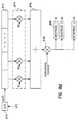
- Figure 2ais a block diagram of a 36 stage linear shift register suitable for use with long spreadingcode of the code generator of the present invention.
- Figure 2bis a block diagram of circuitry which illustrates the feed-forward operation of the code generator.
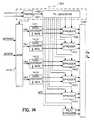
- Figure 2cis a block diagram of an exemplary code generator of the present invention including circuitry for generating spreading code sequences from the long spreading codes and the short spreading codes.
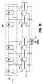
- Figure 2dis an alternate embodiment of the code generator circuit including delay elements to compensate for electrical circuit delays.
- Figure 3ais a graph of the constellation points of the pilot spreading code QPSK signal.
- Figure 3bis a graph of the constellation points of the message channel QPSK signal.
- Figure 3cis a block diagram of exemplary circuitry which implements the method of tracking the received spreading code phase of the present invention.
- Figure 4is a block diagram of the tracking circuit that tracks the median of the received multipath signal components.
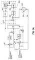
- Figure 5ais a block diagram of the tracking circuit that tracks the centroid of the received multipath signal components.
- Figure 5bis a block diagram of the Adaptive Vector Correlator.
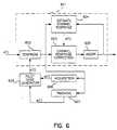
- Figure 6is a block diagram of exemplary circuitry which implements the acquisition decision method of the correct spreading code phase of the received pilot code of the present invention.
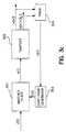
- Figure 7is a block diagram of an exemplary pilot rake filter which includes the tracking circuit and digital phase locked loop for despreading the pilot spreading code, and generator of the weighting factors of the present invention.
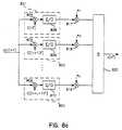
- Figure 8ais a block diagram of an exemplary adaptive vector correlator and matched filter for despreading and combining the multipath components of the present invention.
- Figure 8bis a block diagram of an alternative implementation of the adaptive vector correlator and adaptive matched filter for despreading and combining the multipath components of the present invention.
- Figure 8cis a block diagram of an alternative embodiment of the adaptive vector correlator and adaptive matched filter for despreading and combining the multipath components of the present invention.
- Figure 8dis a block diagram of the Adaptive Matched Filter of one embodiment of the present invention.
- FIG. 9is a block diagram of the elements of an exemplary radio carrier station (RCS) of the present invention.
- RCSradio carrier station
- Figure 10is a block diagram of the elements of an exemplary multiplexer suitable for use in the RCS shown in Figure 9.
- FIG 11is a block diagram of the elements of an exemplary wireless access controller (WAC) of the RCS shown in Figure 9.
- WACwireless access controller
- FIG. 12is a block diagram of the elements of an exemplary modem interface unit (MIU) of the RCS shown in Figure 9.
- MIUmodem interface unit
- Figure 13is a high level block diagram showing the transmit, receive, control, and code generation circuitry of the CDMA modem.
- Figure 14is a block diagram of the transmit section of the CDMA modem.
- Figure 15is a block diagram of an exemplary modem input signal receiver.
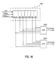
- Figure 16is a block diagram of an exemplary convolutional encoder as used in the present invention.
- Figure 17is a block diagram of the receive section of the CDMA modem.
- Figure 18is a block diagram of an exemplary adaptive matched filter as used in the CDMA modem receive section.
- Figure 19is a block diagram of an exemplary pilot rake as used in the CDMA modem receive section.
- Figure 20is a block diagram of an exemplary auxiliary pilot rake as used in the CDMA modem receive section.
- FIG. 21is a block diagram of an exemplary video distribution circuit (VDC) of the RCS shown in Figure 9.
- VDCvideo distribution circuit
- Figure 22is a block diagram of an exemplary RF transmitter/receiver and exemplary power amplifiers of the RCS shown in Figure 9.
- FIG. 23is a block diagram of an exemplary subscriber unit (SU) of the present invention.
- Figure 24is a flow-chart diagram of an exemplary call establishment algorithm for an incoming call request used by the present invention for establishing a bearer channel between an RCS and an SU.
- Figure 25is a flow-chart diagram of an exemplary call establishment algorithm for an outgoing call request used by the present invention for establishing a bearer channel between an RCS and an SU.
- Figure 26is a flow-chart diagram of an exemplary maintenance power control algorithm of the present invention.
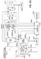
- Figure 27is a flow-chart diagram of an exemplary automatic forward power control algorithm of the present invention.
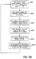
- Figure 28is a flow-chart diagram of an exemplary automatic reverse power control algorithm of the present invention.
- Figure 29is a block diagram of an exemplary closed loop power control system of the present invention when the bearer channel is established.
- Figure 30is a block diagram of an exemplary closed loop power control system of the present invention during the process of establishing the bearer channel.
- GLOSSARY OF ACRONYMS Acronym DefinitionAC Assigned Channels A/D Analog-to-Digital ADPCM Adaptive Differential Pulse Code Modulation AFPC Automatic Forward Power Control AGC Automatic Gain Control AMF Adaptive Matched Filter APC Automatic Power Control ARPC Automatic Reverse Power Control ASPT Assigned Pilot
- AVCAdaptive Vector Correlator AXCH Access Channel B-CDMA Broadband Code Division Multiple Access BCM Bearer Channel Modification BER Bit Error Rate BS Base Station CC Call Control CDM Code Division Multiplex CDMA Code Division Multiple Access CLK Clock Signal Generator CO Central Office CTCH Control Channel CUCH Check-Up Channel dB Decibels DCC Data Combiner Circuitry DI Distribution Interface DLL Delay Locked Loop DM Delta Modulator DS Direct Sequence EPIC Extended PCM Interface Controller FBCH Fast Broadcast Channel FDM Frequency Division Multiplex FD/TD
- the system of the present inventionprovides local-loop telephone service using radio links between one or more base stations and multiple remote subscriber units.
- a radio linkis described for a base station communicating with a fixed subscriber unit (FSU), but the system is equally applicable to systems including multiple base stations with radio links to both FSUs and Mobile Subscriber Units (MSUs). Consequently, the remote subscriber units are referred to herein as Subscriber Units (SUs).
- FSUfixed subscriber unit
- MSUsMobile Subscriber Units
- Base Station (BS) 101provides call connection to a local exchange (LE) 103 or any other telephone network switching interface, such as a private branch exchange (PBX) and includes a Radio Carrier Station (RCS) 104.
- RCSs 104, 105, 110connect to a Radio Distribution Unit (RDU) 102 through links 131, 132, 137, 138, 139, and RDU 102 interfaces with LE 103 by transmitting and receiving call set-up, control, and information signals through telco links 141, 142, 150.
- SUs 116, 119communicate with the RCS 104 through radio links 161, 162, 163, 164, 165.
- another embodiment of the inventionincludes several SUs and a "master" SU with functionality similar to the RCS. Such an embodiment may or may not have connection to a local telephone network.
- the radio links 161 to 165operate within the frequency bands of the DCS1800 standard (1.71 - 1.785 Ghz and 1.805 - 1.880 GHz); the US-PCS standard (1.85 - 1.99 Ghz); and the CEPT standard (2.0 -2.7 GHz). Although these bands are used in described embodiment, the invention is equally applicable to the entire UHF to SHF bands, including bands from 2.7 GHz to 5 GHz.
- the transmit and receive bandwidthsare multiples of 3.5 MHz starting at 7 MHz, and multiples of 5 MHz starting at 10 MHz, respectively.
- the described systemincludes bandwidths of 7, 10, 10.5, 14 and 15 MHz.
- the minimum guard band between the Uplink and Downlinkis 20 MHz, and is desirably at least three times the signal bandwidth.
- the duplex separationis between 50 to 175 MHz, with the described invention using 50, 75, 80, 95, and 175 MHz. Other frequencies may also be used.
- the described embodimentuses different spread-spectrum bandwidths centered around a carrier for the transmit and receive spread-spectrum channels
- the present methodis readily extended to systems using multiple spread-spectrum bandwidths for the transmit channels and multiple spread-spectrum bandwidths for the receive channels.
- an embodimentmay employ the same spread-spectrum channel for both the transmit and receive path channels.
- Uplink and Downlink transmissionscan occupy the same frequency band.
- the present methodmay be readily extended to multiple CDMA frequency bands, each conveying a respectively different set of messages, uplink, downlink or uplink and downlink.
- the spread binary symbol informationis transmitted over the radio links 161 to 165 using Quadrature Phase Shift Keying (QPSK) modulation with Nyquist Pulse Shaping in the present embodiment, although other modulation techniques may be used, including, but not limited to, Offset QPSK (OQPSK) and Minimum Shift Keying (MSK).
- QPSKQuadrature Phase Shift Keying
- OFDMOffset QPSK
- MSKMinimum Shift Keying
- GPSKGaussian Phase Shift Keying
- MPSKM-ary Phase Shift Keying
- the radio links 161 to 165incorporate Broadband Code Division Multiple Access (B-CDMATM) as the mode of transmission in both the Uplink and Downlink directions.
- B-CDMATMBroadband Code Division Multiple Access
- CDMAalso known as Spread Spectrum
- the system describedutilizes the Direct Sequence (DS) spreading technique.
- the CDMA modulatorperforms the spread-spectrum spreading code sequence generation, which can be a pseudonoise (PN) sequence; and complex DS modulation of the QPSK signals with spreading code sequences for the In-phase (I) and Quadrature (Q) channels.
- PNpseudonoise
- QQuadrature
- Pilot signalsare generated and transmitted with the modulated signals, and pilot signals of the present embodiment are spreading codes not modulated by data.
- the pilot signalsare used for synchronization, carrier phase recovery, and for estimating the impulse response of the radio channel.
- Each SUincludes a single pilot generator and at least one CDMA modulator and demodulator, together known as a CDMA modem.
- Each RCS 104, 105, 110has a single pilot generator plus sufficient CDMA modulators and demodulators for all of the logical channels in use by all SUs.
- the CDMA demodulatordespreads the signal with appropriate processing to combat or exploit multipath propagation effects. Parameters concerning the received power level are used to generate the Automatic Power Control (APC) information which, in turn, is transmitted to the other end of the communication link.
- the APC informationis used to control transmit power of the automatic forward power control (AFPC) and automatic reverse power control (ARPC) links.
- each RCS 104, 105 and 110can perform Maintenance Power Control (MPC), in a manner similar to APC, to adjust the initial transmit power of each SU 111, 112, 115, 117 and 118. Demodulation is coherent where the pilot signal provides the phase reference.
- MPCMaintenance Power Control
- the described radio linkssupport multiple traffic channels with data rates of 8, 16, 32, 64, 128, and 144 kb/s.
- the physical channel to which a traffic channel is connectedoperates with a 64k symbol/sec rate.
- Other data ratesmay be supported, and Forward Error Correction (FEC) coding can be employed.
- FECForward Error Correction
- FEC with coding rate of 1/2 and constraint length 7is used.
- Other rates and constraint lengthscan be used consistent with the code generation techniques employed.
- Receiversinclude Adaptive Matched Filters (AMFs) (not shown in Figure 1) which combine the multipath signals.
- AMFsAdaptive Matched Filters
- the exemplary AMFsperform Maximal Ratio Combining.
- RCS 104interfaces to RDU 102 through links 131, 132, 137 with, for example, 1.544 Mb/s DS1, 2.048 Mb/s E1; or HDSL Formats to receive and send digital data signals. While these are typical telephone company standardized interfaces, the present invention is not limited to these digital data formats only.
- the exemplary RCS line interface(not shown in Figure 1) translates the line coding (such as HDB3, B8ZS, AMI) and extracts or produces framing information, performs Alarms and Facility signaling functions, as well as channel specific loop-back and parity check functions.
- the interfaces for this descriptionprovide 64 kb/s PCM encoded or 32 kb/s ADPCM encoded telephone traffic channels or ISDN channels to the RCS for processing. Other ADPCM encoding techniques can be used consistent with the sequence generation techniques.
- the system of the present inventionalso supports bearer rate modification between the RCS 104 and each SU 111, 112, 115, 117 and 118 communicating with RCS 104 in which a CDMA message channel supporting 64 kb/s may be assigned to voiceband data or FAX when rates above 4.8 kb/s are present.
- a CDMA message channel supporting 64 kb/smay be assigned to voiceband data or FAX when rates above 4.8 kb/s are present.
- Such 64 kb/s bearer channelis considered an unencoded channel.
- bearer rate modificationmay be done dynamically, based upon the D channel messages.
- each SU 111, 112, 115, 117 and 118either includes or interfaces with a telephone unit 170, or interfaces with a local switch (PBX) 171.
- the input from the telephone unitmay include voice, voiceband data and signaling.
- the SUtranslates the analog signals into digital sequences, and may also include a Data terminal 172 or an ISDN interface 173.
- the SUcan differentiate voice input, voiceband data or FAX and digital data.
- the SUencodes voice data with techniques such as ADPCM at 32 kb/s or lower rates, and detects voiceband data or FAX with rates above 4.8 kb/s to modify the traffic channel (bearer rate modification) for unencoded transmission.
- A-law, u-law, or no companding of the signalmay be performed before transmission.
- data compression techniquessuch as idle flag removal, may also be used to conserve capacity and minimize interference.
- the transmit power levels of the radio interface between RCS 104 and SUs 111, 112, 115, 117 and 118are controlled using two different closed loop power control methods.
- the Automatic Forward Power Control (AFPC) methoddetermines the Downlink transmit power level
- the Automatic Reverse Power Control (ARPC) methoddetermines the Uplink transmit power level.
- the logical control channel by which SU 111 and RCS 104, for example, transfer power control informationoperates at least a 16 kHz update rate. Other embodiments may use a faster or slower update rate for example 64 kHz.
- the systemuses an optional maintenance power control method during the inactive mode of a SU.
- the unitWhen SU 111 is inactive or powered-down to conserve power, the unit occasionally activates to adjust its initial transmit power level setting in response to a maintenance power control signal from RCS 104.
- the maintenance power signalis determined by the RCS 104 by measuring the received power level of SU 111 and present system power level and, from this, calculates the necessary initial transmit power.
- the methodshortens the channel acquisition time of SU 111 to begin a communication.
- the methodalso prevents the transmit power level of SU 111 from becoming too high and interfering with other channels during the initial transmission before the closed loop power control reduces the transmit power.
- RCS 104obtains synchronization of its clock from an interface line such as, but not limited to, E1, T1, or HDSL interfaces.
- RCS 104can also generate its own internal clock signal from an oscillator which may be regulated by a Global Positioning System (GPS) receiver.
- GPSGlobal Positioning System
- RCS 104generates a Global Pilot Code, a channel with a spreading code but no data modulation, which can be acquired by remote SUs 111 through 118. All transmission channels of the RCS are synchronized to the Pilot channel, and spreading code phases of code generators (not shown) used for Logical communication channels within RCS 104 are also synchronized to the Pilot channel's spreading code phase.
- SUs 111 through 118which receive the Global Pilot Code of RCS 104 synchronize the spreading and de-spreading code phases of the code generators (not shown) of the SUs to the Global Pilot Code.
- RCS 104, SU 111, and RDU 102may incorporate system redundancy of system elements and automatic switching between internal functional system elements upon a failure event to prevent loss or drop-out of a radio link, power supply, traffic channel, or group of traffic channels.
- a 'channel' of the prior artis usually regarded as a communications path which is part of an interface and which can be distinguished from other paths of that interface without regard to its content.
- CDMACode Division Multiple Access
- separate communications pathsare distinguished only by their content.
- the term 'logical channel'is used to distinguish the separate data streams, which are logically equivalent to channels in the conventional sense. All logical channels and sub-channels of the present invention are mapped to a common 64 kilo-symbols per second (ksym/s) QPSK stream. Some channels are synchronized to associated pilot codes which are generated from, and perform a similar function to the system Global Pilot Code (GPC). The system pilot signals are not, however, considered logical channels.
- GPSGlobal Pilot Code
- Logical communication channelsare divided into two groups: the Global Channel (GC) group includes channels which are either transmitted from the base station RCS to all remote SUs or from any SU to the RCS of the base station regardless of the SU's identity.
- the channels in the GC groupmay contain information of a given type for all users including those channels used by SUs to gain system access.
- Channels in the Assigned Channels (AC) groupare those channels dedicated to communication between the RCS and a particular SU.
- the Global Channels (GC) groupprovides for 1) Broadcast Control logical channels, which provide point to multipoint services for broadcasting messages to all SUs and paging messages to SUs; and 2) Access Control logical channels which provide point-to-point services on global channels for SUs to access the system and obtain assigned channels.
- the RCS of the present inventionhas multiple Access Control logical channels, and one Broadcast Control group.
- An SU of the present inventionhas at least one Access Control channel and at least one Broadcast Control logical channel.
- the Global logical channels controlled by the RCSare the Fast Broadcast Channel (FBCH) which broadcasts fast changing information concerning which services and which access channels are currently available, and the Slow Broadcast Channel (SBCH) which broadcasts slow changing system information and paging messages.
- the Access Channel (AXCH)is used by the SUs to access an RCS and gain access to assigned channels. Each AXCH is paired with a Control Channel (CTCH).
- CTCHControl Channel
- the CTCHis used by the RCS to acknowledge and reply to access attempts by SUs.
- the Long Access Pilot (LAXPT)is transmitted synchronously with AXCH to provide the RCS with a time and phase reference.
- An Assigned Channel (AC) groupcontains the logical channels that control a single telecommunication connection between the RCS and an SU.
- the functions developed when an AC group is formedinclude a pair of power control logical message channels for each of the Uplink and Downlink connections, and depending on the type of connection, one or more pairs of traffic channels.
- the Bearer Control functionperforms the required forward error control, bearer rate modification, and encryption functions.
- Each SU 111, 112, 115, 117 and 118has at least one AC group formed when a telecommunication connection exists, and each RCS 104, 105 and 110 has multiple AC groups formed, one for each connection in progress.
- An AC group of logical channelsis created for a connection upon successful establishment of the connection.
- the AC groupincludes encryption, FEC coding, and multiplexing on transmission, and FEC decoding, decryption and demultiplexing on reception.
- Each AC groupprovides a set of connection oriented point-to-point services and operates in both directions between a specific RCS, for example, RCS 104 and a specific SU, for example, SU 111.
- An AC group formed for a connectioncan control more than one bearer over the RF communication channel associated with a single connection. Multiple bearers are used to carry distributed data such as, but not limited to, ISDN.
- An AC groupcan provide for the duplication of traffic channels to facilitate switch over to 64 kb/s PCM for high speed facsimile and modem services for the bearer rate modification function.
- the assigned logical channels formed upon a successful call connection and included in the AC groupare a dedicated signaling channel [order wire (OW)], an APC channel, and one or more Traffic channels (TRCH) which are bearers of 8, 16, 32, pr 64 kb/s depending on the service supported.
- OWorder wire
- TRCHTraffic channels
- voice trafficmoderate rate coded speech
- ADPCMADPCM
- PCMPCM
- two 64 kb/s TRCHsform the B channels and a 16 kb/s TRCH forms the D channel.
- the APC subchannelmay either be separately modulated on its own CDMA channel, or may be time division multiplexed with a traffic channel or OW channel.
- Each SU 111, 112, 115, 117 and 118 of the present inventionsupports up to three simultaneous traffic channels.
- the mapping of the three logical channels for TRCHs to the user datais shown below in Table 1: Mapping of service types to the three available TRCH channels Service TRCH(0) TRCH(1) TRCH(2) 16 kb/s POTS TRCH /16 not used not used 32 + 64 kb/s POTS (during BCM) TRCH /32 TRCH /64 not used 32 kb/s POTS TRCH /32 not used not used 64 kb/s POTS not used TRCH /64 not used ISDN D not used not used TRCH /16 ISDN B+D TRCH /64 not used TRCH/16 ISDN 2B + D TRCH /64 TRCH /64 TRCH /16 Digital LL @ 64 kb/s TRCH /64 not used not used Digital LL @ 2 x 64 kb/s TRCH /64 TRCH /64 not used Analog LL @ 64 kb/s
- the APC data rateis sent at 64 kb/s.
- the APC logical channelis not FEC coded to avoid delay and is transmitted at a relatively low power level to minimize capacity used for APC.
- the APC and OWmay be separately modulated using complex spreading code sequences, or they may be time division multilplexed.
- the OW logical channelis FEC coded with a rate 1/2 convolutional code. This logical channel is transmitted in bursts when signaling data is present to reduce interference. After an idle period, the OW signal begins with at least 35 symbols prior to the start of the data frame. For silent maintenance call data, the OW is transmitted continuously between frames of data. Table 2 summarizes the logical channels used in the exemplary embodiment:
- the CDMA code generators used to encode the logical channels of the present inventionemploy Linear Shift Registers (LSRs) with feedback logic which is a method well known in the art.
- LSRsLinear Shift Registers
- the code generators of the present embodiment of the inventiongenerate 64 synchronous unique sequences. Each RF communication channel uses a pair of these sequences for complex spreading (in-phase and quadrature) of the logical channels, so the generator gives 32 complex spreading sequences.
- the sequencesare generated by a single seed which is initially loaded into a shift register circuit.
- the spreading code period of the present inventionis defined as an integer multiple of the symbol duration, and the beginning of the code period is also the beginning of the symbol.
- the relation between bandwidths and the symbol lengths chosen for the exemplary embodiment of the present inventionis: BW (MHZ) L(chips/symbol) 7 91 10 130 10.5 133 14 182 15 195
- the spreading code lengthis also a multiple of 64 and of 96 for ISDN frame support.
- the spreading codeis a sequence of symbols, called chips or chip values.
- the general methods of generating pseudorandom sequences using Galois Field mathematicsis known to those skilled in the art; however, a unique set, or family, of code sequences has been derived for the present invention.
- the length of the linear feedback shift register to generate a code sequenceis chosen, and the initial value of the register is called a "seed".
- the constraintis imposed that no code sequence generated by a code seed may be a cyclic shift of another code sequence generated by the same code seed.
- no code sequence generated from one seedmay be a cyclic shift of a code sequence generated by another seed.
- the spreading codesare generated by combining a linear sequence of period 233415 and a nonlinear sequence of period 128
- the FBCH channel of the exemplary embodimentis an exception because it is not coded with the 128 length sequence, so the FBCH channel spreading code has period 233415.
- the nonlinear sequence of length 128is implemented as a fixed sequence loaded into a shift register with a feed-back connection.
- the fixed sequencecan be generated by an m-sequence of length 127 padded with an extra logic 0, 1, or random value as is well known in the art.
- the feedback connectionscorrespond to a irreducible polynomial h(n) of degree 36.
- a group of "seed" values for a LFSR representing the polynomial h(x) of equation (2) which generates code sequences that are nearly orthogonal with each otheris determined.
- the first requirement of the seed valuesis that the seed values do not generate two code sequences which are simply cyclic shifts of each other.
- Every element of GF(2 36 )can also be written as a power of ⁇ reduced modulo h(x). Consequently, the seeds are represented as powers of ⁇ , the primitive element.
- the solution for the order of an elementdoes not require a search of all values; the order of an element divides the order of the field (GF(2 36 )).
- ⁇is any element of GF(2 36 ) with x e ⁇ 1 for some e, then e 2 36 -1. Therefore, the order of any element in GF(2 36 ) divides 2 36 -1.
- the present inventionincludes a method to increase the number of available seeds for use in a CDMA communication system by recognizing that certain cyclic shifts of the previously determined code sequences may be used simultaneously.
- the round trip delay for the cell sizes and bandwidths of the present inventionare less than 3000 chips.
- sufficiently separated cyclic shifts of a sequencecan be used within the same cell without causing ambiguity for a receiver attempting to determine the code sequence. This method enlarges the set of sequences available for use.
- all secondary seeds of the present inventionare derived from the primary seeds by shifting them multiples of 4095 chips modulo h(x). Once a family of seed values is determined, these values are stored in memory and assigned to logical channels as necessary. Once assigned, the initial seed value is simply loaded into LFSR to produce the required spreadingcode sequence associated with the seed value.
- the present embodiment of the inventionincludes a new method of generating code sequences that have rapid acquisition properties by using one or more of the following methods.
- a long codemay be constructed from two or more short codes.
- a method of transmitting complex valued spreading code sequencesin-phase (I) and Quadrature (Q) sequences
- Two or more separate code sequencesmay be transmitted over the complex channels. If the sequences have different phases, an acquisition may be done by acquisition circuits in parallel over the different code sequences when the relative phase shift between the two or more code channels is known. For example, for two sequences, one can be sent on an In phase (I) channel and one on the Quadrature (Q) channel. To search the code sequences, the acquisition detection means searches the two channels, but begins the (Q) channel with an offset equal to one-half of the spreading code sequence length.
- the acquisition meansstarts the search at N/2 on the (Q) channel.
- the average number of tests to find acquisitionis N/2 for a single code search, but searching the (I) and phase delayed (Q) channel in parallel reduces the average number of tests to N/4.
- the codes sent on each channelcould be the same code, the same code with one channel's code phase delayed, or different code sequences.
- the long complex spreading codes used for the exemplary system of the present inventionhave a number of chips after which the code repeats.
- the repetition period of the spreading sequenceis called an epoch.
- the present inventionuses an Epoch and Sub-epoch structure.
- the code period for the CDMA spreading code to modulate logical channelsis 29877120 chips/code period which is the same number of chips for all bandwidths.
- the code periodis the epoch of the present invention, and Table 3 below defines the epoch duration for the supported chip rates.
- two sub-epochsare defined over the spreading code epoch and are 233415 chips and 128 chips long.
- the 233415 chip sub-epochis referred to as a long sub-epoch, and is used for synchronizing events on the RF communication interface such as encryption key switching and changing from global to assigned codes.
- the 128 chip short epochis defined for use as an additional timing reference.
- the highest symbol rate used with a single CDMA codeis 64 ksym/s. There is always an integer number of chips in a symbol duration for the supported symbol rates 64, 32, 16, and 8 ksym/s.
- Chip RatesBandwidth (MHz) Chip Rate, Complex (Mchip/sec) number of chips in a 64 kbit/sec symbol 128 chip sub-epoch duration ( ⁇ s) 233415 chip sub-epoch duration (ms) Epoch duration (sec) 7 5.824 91 21.978 40.078 5.130 10 8.320 130 15.385 28.055 3.591 10.5 8.512 133 15.038 27.422 3.510 14 11.648 182 10.989 20.039 2.565 15 12.480 195 10.256 18.703 2.394
- the complex spreading codesare designed such that the beginning of the sequence epoch coincides with the beginning of a symbol for all of the bandwidths supported.
- the present inventionsupports bandwidths of 7, 10, 10.5, 14, and 15 MHz. Assuming nominal 20% roll-off, these bandwidths correspond to the following chip rates in Table 4. Supported Bandwidths and Chip Rates for CDMA.
- the beginning of an interleaver periodcoincides with the beginning of the sequence epoch.
- the spreading sequences generated using the method of the present inventioncan support interleaver periods that are multiples of 1.5 ms for various bandwidths.
- Cyclic sequences of the prior artare generated using linear feedback shift register (LFSR) circuits.
- LFSRlinear feedback shift register
- This methoddoes not generate sequences of even length.
- One embodiment of the spreading code sequence generator using the code seeds generated previouslyis shown in Figure 2a, Figure 2b, and Figure 2c.
- the symbol ⁇represents a binary addition (EXCLUSIVE-OR).
- a sequence generator designed as abovegenerates the in-phase and quadrature parts of a set of complex sequences.
- the tap connections and initial state of the 36 stage LFSRdetermine the sequence generated by this circuit.
- the tap coefficients of the 36 stage LFSRare determined such that the resulting sequences have the period 233415. Note that the tap connections shown in Figure 2a correspond to the polynomial given in equation (2).
- Each resulting sequenceis then overlaid by binary addition with the 128 length sequence C* to obtain the epoch period 29877120.
- FIG. 2bshows a Feed Forward (FF) circuit 202 which is used in the code generator.
- the signal X[n-1]is output of the chip delay 211, and the input of the chip delay 211 is X[n].
- the code chip C[n]is formed by the logical adder 212 from the input X[n] and X[n-1].
- PN sequencem-sequence
- the even code sequence C *is input to the even code shift register 221, which is a cyclic register, that continually outputs the sequence.
- the short sequenceis then combined with the long sequence using an EXCLUSIVE-OR operation 213, 214, 220.
- up to 63 spreadingcode sequences C o through C 63are generated by tapping the output signals of FFs 203 and logically adding the short sequence C* in binary adders 213, 214, and 220, for example.
- FF 203will create a cumulative delay effect for the code sequences produced at each FF stage in the chain. This delay is due to the nonzero electrical delay in the electronic components of the implementation.
- the timing problems associated with the delaycan be mitigated by inserting additional delay elements into the FF chain in one version of the embodiment of the invention.
- the FF chain of Figure 2c with additional delay elementsis shown in Figure 2d.
- the code-generators in the exemplary embodiment of the present inventionare configured to generate either global codes, or assigned codes.
- Global codesare CDMA codes that can be received or transmitted by all users of the system.
- Assigned codesare CDMA codes that are allocated for a particular connection.
- a set of sequencesare generated from the same generator as described, only the seed of the 36 stage LFSR is specified to generate a family of sequences. Sequences for all the global codes, are generated using the same LFSR circuit. Therefore, once an SU has synchronized to the Global pilot signal from an RCS and knows the seed for the LFSR circuit for the Global Channel codes, it can generate not only the pilot sequence but also all other global codes used by the RCS.
- the signal that is upconverted to RFis generated as follows.
- the output signals of the above shift register circuitsare converted to an antipodal sequence (0 maps into +1, 1 maps into -1).
- the Logical channelsare initially converted to QPSK signals, which are mapped as constellation points as is well known in the art.
- the In-phase and Quadrature channels of each QPSK signalform the real and imaginary parts of the complex data value.
- two spreading codesare used to form complex spreading chip values.
- the complex dataare spread by being multiplied by the complex spreading code.
- the received complex datais correlated with the conjugate of the complex spreading code to recover despread data.
- Short codesare used for the initial ramp-up process when an SU accesses an RCS.
- the period of the short codesis equal to the symbol duration and the start of each period is aligned with a symbol boundary.
- Both SU and RCSderive the real and imaginary parts of the short codes from the last eight feed-forward sections of the sequence generator producing the global codes for that cell.
- the short codes that are in use in the exemplary embodiment of the inventionare updated every 3 ms. Other update times that are consistent with the symbol rate may be used. Therefore, a change-over occurs every 3 ms starting from the epoch boundary. At a change-over, the next symbol length portion of the corresponding feed-forward output becomes the short code.
- the SUneeds to use a particular short code, it waits until the first 3 ms boundary of the next epoch and stores the next symbol length portion output from the corresponding FF section. This shall be used as the short code until the next change-over, which occurs 3 ms later.
- SAXPTsShort Access Channel pilots
- the seed values for the 36 bit shift registerare chosen to avoid using the same code, or any cyclic shift of the same code, within the same geographical area to prevent ambiguity or harmful interference.
- No assigned codeis equal to, or a cyclic shift of a global code.
- the pilot signalsare used for synchronization, carrier phase recovery, and for estimating the impulse response of the radio channel.
- the RCS 104transmits a forward link pilot carrier reference as a complex pilot code sequence to provide time and phase reference for all SUs 111, 112, 115, 117 and 118 in its service area.
- the power level of the Global Pilot (GLPT) signalis set to provide adequate coverage over the whole RCS service area, which area depends on the cell size. With only one pilot signal in the forward link, the reduction in system capacity due to the pilot energy is negligible.
- the SUs 111, 112, 115, 117 and 118each transmits a pilot carrier reference as a quadrature modulated (complex-valued) pilot spreading code sequence to provide a time and phase reference to the RCS for the reverse link.
- the pilot signal transmitted by the SU of one embodiment of the inventionis 6 dB lower than the power of the 32 kb/s POTS traffic channel.
- the reverse pilot channelis subject to APC.
- the reverse link pilot associated with a particular connectionis called the Assigned Pilot (ASPT).
- APCAssigned Pilot
- the complex pilot signalsare de-spread by multiplication with conjugate spreading codes: ⁇ (C 2 ⁇ C*) - j.(C 3 ⁇ C*) ⁇ .
- the GLPT constellationis shown in Figure 3a, and the TRCH n traffic channel constellation is shown in Figure 3b.
- the FBCHis a global forward link channel used to broadcast dynamic information about the availability of services and AXCHs. Messages are sent continuously over this channel, and each message lasts approximately 1 ms.
- the FBCH messageis 16 bits long, repeated continuously, and is epoch aligned.
- the FBCHis formatted as defined in Table 6.
- FBCH format Bit Definition0 Traffic Light 0 1 Traffic Light 1 2 Traffic Light 2 3 Traffic Light 3 4-7 service indicator bits 8 Traffic Light 0 9 Traffic Light 1 10 Traffic Light 2 11 Traffic Light 3 12-15 service indicator bits
- a traffic lightcorresponds to an Access Channel (AXCH) and indicates whether the particular access channel is currently in use (a red) or not in use (a green).
- a logic '1'indicates that the traffic light is green, and a logic '0' indicates the traffic light is red.
- the values of the traffic light bitsmay change from octet to octet, and each 16 bit message contains distinct service indicator bits which describe the types of services that are available for the AXCHs.
- One embodiment of the present inventionuses service indicator bits as follows to indicate the availability of services or AXCHs.
- the service indicator bits ⁇ 4,5,6,7,12,13,14,15 ⁇ taken togethermay be an unsigned binary number, with bit 4 as the MSB and bit 15 as the LSB.
- Each service type incrementhas an associated nominal measure of the capacity required, and the FBCH continuously broadcasts the available capacity. This is scaled to have a maximum value equivalent to the largest single service increment possible.
- an SUrequires a new service or an increase in the number of bearers, it compares the capacity required to that indicated by the FBCH, and then considers itself blocked if the capacity is not available.
- the FBCH and the traffic channelsare aligned to the epoch.
- Slow Broadcast Information framescontain system or other general information that is available to all SUs and Paging Information frames contain information about call requests for particular SUs.
- Slow Broadcast Information frames and Paging Information framesare multiplexed together on a single logical channel which forms the Slow Broadcast Channel (SBCH).
- SBCHSlow Broadcast Channel
- the code epochis a sequence of 29 877 20 chips having an epoch duration which is a function of the chip rate defined in Table 7 below.
- the channelis divided into N "Sleep" Cycles, and each Cycle is subdivided into M Slots, which are 19 ms long, except for 10.5 Mhz bandwidth which has slots of 18 ms.
- Sleep Cycle Slot #1is always used for slow broadcast information. Slots #2 to #M-1 are used for paging groups unless extended slow broadcast information is inserted.
- the pattern of cycles and slots in one embodiment of the present inventionrun continuously at 16 kb/s.
- the SUpowers-up the receiver and re-acquires the pilot code. It then achieves carrier lock to a sufficient precision for satisfactory demodulation and Viterbi decoding.
- the settling time to achieve carrier lockmay be up to 3 Slots in duration. For example, an SU assigned to Slot #7 powers up the Receiver at the start of Slot #4. Having monitored its Slot the SU will have either recognized its Paging Address and initiated an access request, or failed to recognize its Paging Address in which case it reverts to the Sleep mode.
- Table 8shows duty cycles for the different bandwidths, assuming a wake-up duration of 3 Slots. Sleep-Cycle Power Saving Bandwidth (MHz) Slots/Cycle Duty Cycle 7.0 54 7.4% 10.0 63 6.3% 10 5 65 6.2% 14.0 45 8.9% 15.0 63 6.3%
- the firstis the prior art tracking circuit which simply tracks the spreading code phase with the highest detector output signal value
- the secondis a tracking circuit that tracks the median value of the code phase of the group of multipath signals
- the thirdis the centroid tracking circuit which tracks the code-phase of an optimized, least mean squared weighted average of the multipath signal components.
- the followingdescribes the algorithms by which the spreading code phase of the received CDMA signal is tracked.
- a tracking circuithas operating characteristics that reveal the relationship between the time error and the control voltage that drives a Voltage Controlled Oscillator (VCO) of a spreading code phase tracking circuit.
- VCOVoltage Controlled Oscillator
- the tracking circuitWhen there is a positive timing error, the tracking circuit generates a negative control voltage to offset the timing error.
- the tracking circuitWhen there is a negative timing error, the tracking circuit generates a positive control voltage to offset the timing error.
- the tracking circuitWhen the tracking circuit generates a zero value, this value corresponds to the perfect time alignment called the 'lock-point'.
- Figure 3shows the basic tracking circuit. Received signal r(t) is applied to matched filter 301, which correlates r(t) with a local code-sequence c(t) generated by Code Generator 303.
- the output signal of the matched filter x(t)is sampled at the sampler 302 to produce samples x[nT] and x[nT + T/2].
- the samples x[nT] and x[nT + T/2]are used by a tracking circuit 304 to determine if the phase of the spreading code c(t) of the code generator 303 is correct.
- the tracking circuit 304produces an error signal e(t) as an input to the code generator 303.
- the code generator 303uses this signal e(t) as an input signal to adjust the code-phase it generates.
- the signal transmitted by the reference useris written in the lowpass representation as where c k represents the spreading code coefficients, P Tc (t) represents the spreading code chip waveform, and T c is the chip duration. Assuming that the reference user is not transmitting data so that only the spreading code modulates the carrier. Referring to Figure 3c, the received signal is
- a iis due to fading effect of the multipath channel on the i-th path and ⁇ i is the random time delay associated with the same path.
- the receiverpasses the received signal through a matched filter, which is implemented as a correlation receiver and is described below. This operation is done in two steps: first the signal is passed through a chip matched filter and sampled to recover the spreading code chip values, then this chip sequence is correlated with the locally generated code sequence.
- Figure 3cshows the chip matched filter 301, matched to the chip waveform P Tc (t) , and the sampler 302.
- h R (t)is the impulse response of the chip matched filter and '*' denotes convolution.
- the order of the summationscan be rewritten as where
- the samplersamples the output signal of the matched filter to produce x(nT) at the maximum power level points of g(t) .
- the waveform g(t)is severely distorted because of the effect of the multipath signal reception, and a perfect time alignment of the signals is not available.
- the received spreading code chip value waveformis distorted, and has a number of local maxima that can change from one sampling interval to another depending on the channel characteristics.
- Prior art tracking methodsinclude a code tracking circuit in which the receiver attempts to determine the timing of the maximum matched filter output value of the chip waveform occurs and sample the signal accordingly.
- the receiver despread code waveformcan have a number of local maxima, especially in a mobile environment.
- f(t)represents the received signal waveform of the spreading code chip convolved with the channel impulse response. The frequency response characteristic of f(t) and the maximum of this characteristic can change rather quickly making it impractical to track the maximum of f(t) .
- the Median Weighted Tracking Method of one embodiment of the present inventionminimizes the absolute weighted error, defined as
- This tracking methodcalculates the 'median' signal value of f(t) by collecting information from all paths, where f( ⁇ ) is as in equation 12.
- the waveform f(t)can have multiple local maxima, but only one median.
- FIG. 4shows an implementation of the tracking circuit based on minimizing the absolute weighted error defined above.
- the signal x(t) and its one-half chip offset version x( t + T/2)are sampled by the A/D 401 at a rate 1/T.
- the following equationdetermines the operating characteristic of the circuit in Figure 4:
- Tracking the median of a group of multipath signalskeeps the received energy of the multipath signal components substantially equal on the early and late sides of the median point of the correct locally generated spreading code phase c n .
- the tracking circuitconsists of an A/D 401 which samples an input signal x(t) to form the half-chip offset samples.
- the half chip offset samplesare alternatively grouped into even samples called an early set of samples x(nT+ ⁇ ) and odd samples called a late set of samples x(nT+(T/2)+ ⁇ ).
- the first correlation bank adaptive matched filter 402multiplies each early sample by the spreading code phases c(n+1), c(n+2), ..., c(n+L), where L is small compared to the code length and approximately equal to number of chips of delay between the earliest and latest multipath signal.
- the output of each correlatoris applied to a respective first sum-and-dump bank 404.
- the magnitudes of the output values of the L sum-and-dumpsare calculated in the calculator 406 and then summed in summer 408 to give an output value proportional to the signal energy in the early multipath signals.
- a second correlation bank adaptive matched filter 403operates on the late samples, using code phases c(n-1), c(n-2), ..., c(n-L), and each output signal is applied to a respective sum-and-dump circuit in an integrator 405.
- the magnitudes of the L sum-and-dump output signalsare calculated in calculator 407 and then summed in summer 409 to give a value for the late multipath signal energy.
- the subtractor 410calculates the difference and produces error signal ⁇ (t) of the early and late signal energy values.
- the tracking circuitadjusts by means of error signal ⁇ ( ⁇ ) the locally generated code phases c(t) to cause the difference between the early and late values to tend toward 0.
- the optimal spreading code tracking circuit of one embodiment of the present inventionis called the squared weighted tracking (or centroid) circuit. Defining ⁇ to denote the time estimate that the tracking circuit calculates, based on some characteristic of f(t) , the centroid tracking circuit minimizes the squared weighted error defined as
- the early and late multipath signal energy on each side of the centroid pointare equal.
- the centroid tracking circuit shown in Figure 5aconsists of an A/D converter 501 which samples an input signal x(t) to form the half-chip offset samples.
- the half chip offset samplesare alternatively grouped as an early set of samples x(nT+ ⁇ ) and a late set of samples x(nT+(T/2)+ ⁇ ).
- the first correlation bank adaptive matched filter 502multiplies each early sample and each late sample by the positive spreading code phases c(n+1), c(n+2), ..., c(n+L), where L is small compared to the code length and approximately equal to number of chips of delay between the earliest and latest multipath signal.
- the output signal of each correlatoris applied to a respective one of L sum-and-dump circuits of the first sum and dump bank 504.
- the magnitude value of each sum-and-dump circuit of the sum and dump bank 504is calculated by the respective calculator in the calculator bank 506 and applied to a corresponding weighting amplifier of the first weighting bank 508.
- the output signal of each weighting amplifierrepresents the weighted signal energy in a multipath component signal.
- the weighted early multipath signal energy valuesare summed in sample adder 510 to give an output value proportional to the signal energy in the group of multipath signals corresponding to positive code phases which are the early multipath signals.
- a second correlation bank adaptive matched filter 503operates on the early and late samples, using the negative spreading code phases c(n-1), c(n-2), ..., c(n-L); each output signal is provided to a respective sum-and-dump circuit of discrete integrator 505.
- the magnitude value of the L sum-and-dump output signalsare calculated by the respective calculator of calculator bank 507 and then weighted in weighting bank 509.
- the weighted late multipath signal energy valuesare summed in sample adder 511 to give an energy value for the group of multipath signals corresponding to the negative code phases which are the late multipath signals.
- the adder 512calculates the difference of the early and late signal energy values to produce error sample value ⁇ ⁇ ).
- the tracking circuit of Figure 5aproduces error signal ⁇ ( ⁇ ) which is used to adjust the locally generated code phase c(nT) to keep the weighted average energy in the early and late multipath signal groups equal.
- the embodiment shownuses weighting values that increase as the distance from the centroid increases. The signal energy in the earliest and latest multipath signals is probably less than the multipath signal values near the centroid. Consequently, the difference calculated by the adder 510 is more sensitive to variations in delay of the earliest and latest multipath signals.
- the tracking circuitadjusts sampling phase to be "optimal" and robust to multipath.
- f(t)represent the received signal waveform as in equation 12 above.
- the particular method of optimizingstarts with a delay locked loop with an error signal ⁇ ( ⁇ ) that drives the loop.
- the optimal form for ⁇ ( ⁇ )has the canonical form: where w(t, ⁇ ) is a weighting function relating f(t) to the error ⁇ ( ⁇ ), and the relationship indicated by equation (24) also holds
- the error ⁇ ( ⁇ )has a deterministic part and a noise part.
- zdenote the noise component in ⁇ ( ⁇ )
- the matrix Bis an L by L matrix and the elements are determined by calculating values such that the ratio F of equation (26) is maximized.
- the Quadratic Detector described abovemay be used to implement the centroid tracking system described above with reference to Figure 5a.
- Ldetermines the minimum number of correlators and sum-and-dump elements. L is chosen as small as possible without compromising the functionality of the tracking circuit.
- the multipath characteristic of the channelis such that the received chip waveform f(t) is spread over QT c seconds, or the multipath components occupy a time period of Q chips duration.
- Qis found by measuring the particular RF channel transmission characteristics to determine the earliest and latest multipath component signal propagation delay.
- QT cis the difference between the earliest and latest multipath component arrival time at a receiver.
- An embodiment of the present inventionuses an adaptive vector correlator (AVC) to estimate the channel impulse response and to obtain a reference value for coherent combining of received multipath signal components.
- AVCadaptive vector correlator
- the described embodimentemploys an array of correlators to estimate the complex channel response affecting each multipath component.
- the receivercompensates for the channel response and coherently combines the received multipath signal components. This approach is referred to as maximal ratio combining.
- the input signal x(t) to the systemincludes interference noise of other message channels, multipath signals of the message channels, thermal noise, and multipath signals of the pilot signal.
- the signalis provided to AVC 601 which, in the exemplary embodiment, includes a despreading means 602, channel estimation means for estimating the channel response 604, correction means for correcting a signal for effects of the channel response 603, and adder 605.
- the AVC despreading means 602is composed of multiple code correlators, with each correlator using a different phase of the pilot code c(t) provided by the pilot code generator 608.
- the output signal of this despreading meanscorresponds to a noise power level if the local pilot code of the despreading means is not in phase with the input code signal.
- the channel response estimation means 604receives the combined pilot signal and the output signals of the despreading means 602, and provides a channel response estimate signal, w(t), to the correction means 603 of the AVC, and the estimate signal w(t) is also available to the adaptive matched filter (AMF) described below.
- AMFadaptive matched filter
- the output signal of the despreading means 602is also provided to the acquisition decision means 606 which decides, based on a particular algorithm such as a sequential probability ratio test (SPRT), if the present output levels of the despreading circuits correspond to synchronization of the locally generated code to the desired input code phase. If the detector finds no synchronization, then the acquisition decision means sends a control signal a(t) to the local pilot code generator 608 to offset its phase by one or more chip period. When synchronization is found, the acquisition decision means informs tracking circuit 607, which achieves and maintains a close synchronization between the received and locally generated code sequences.
- SPRTsequential probability ratio test
- FIG. 7An exemplary implementation of the Pilot AVC used to despread the pilot spreading code is shown in Figure 7.
- the described embodimentassumes that the input signal x(t) has been sampled with sampling period T to form samples x(nT+ ⁇ ), and is composed of interference noise of other message channels, multipath signals of message channels, thermal noise, and multipath signals of the pilot code.
- the signal x(nT+ ⁇ )is applied to L correlators, where L is the number of code phases over which the uncertainty within the multipath signals exists.
- Each correlator 701, 702, 703comprises a multiplier 704, 705, 706, which multiples the input signal with a particular phase of the Pilot spreading code signal c((n+i)T), and sum-and-dump circuits 708, 709, 710.
- each multiplier 704, 705, 706is applied to a respective sum-and dump circuit 708, 709, 710 to perform discrete integration.
- the AVCcompensates for the channel response and the carrier phase rotation of the different multipath signals.
- Each output of each sum-and-dump 708, 709, 710is multiplied with a derotation phaser [complex conjugate of ep(nT)] from digital phase lock loop (DPLL) 721 by the respective multiplier 714, 715, 716 to account for the phase and frequency offset of the carrier signal.
- DPLLdigital phase lock loop
- LPFlow pass filter
- Each despread multipath signalis multiplied by its corresponding weighting factor in a respective multiplier 717, 718, 719.
- the output signals of the multipliers 717, 718, 719are summed in a master adder 720, and the output signal p(nT) of the accumulator 720 consists of the combined despread multipath pilot signals in noise.
- the output signal p(nT)is also input to the DPLL 721 to produce the error signal ep(nT) for tracking of the carrier phase.
- Figures 8a and 8bshow alternate embodiments of the AVC which can be used for detection and multipath signal component combining.
- the message signal AVCs of Figures 8a and 8buse the weighting factors produced by the Pilot AVC to correct the message data multipath signals.
- the spreading code signal, c(nT)is the spreading code spreading sequence used by a particular message channel and is synchronous with the pilot spreading code signal.
- the value Lis the number of correlators in the AVC circuit.
- the circuit of Figure 8acalculates the decision variable Z which is given by where N is the number of chips in the correlation window. Equivalently, the decision statistic is given by
- the input signal x(t)is sampled to form x(nT+ ⁇ ), and is composed of interference noise of other message channels, multipath signals of message channels, thermal noise, and multipath signals of the pilot code.
- the signal x(nT+ ⁇ )is applied to L correlators, where L is the number of code phases over which the uncertainty within the multipath signals exists.
- Each correlator 801, 802, 803comprises a multiplier 804, 805, 806, which multiples the input signal by a particular phase of the message channel spreading code signal, and a respective sum-and-dump circuit 808, 809, 810.
- each multiplier 804, 805, 806is applied to a respective sum-and dump circuit 808, 809, 810 which performs discrete integration.
- the AVCcompensates for the different multipath signals.
- Each despread multipath signal and its corresponding weighting factor, which is obtained from the corresponding multipath weighting factor of the pilot AVC,are multiplied in a respective multiplier 817, 818, 819.
- the output signals of multipliers 817, 818, 819are summed in a master adder 820, and the output signal z(nT) of the accumulator 820 consists of sampled levels of a despread message signal in noise.
- the alternative embodiment of the inventionincludes a new implementation of the AVC despreading circuit for the message channels which performs the sum-and-dump for each multipath signal component simultaneously.
- the advantage of this circuitis that only one sum-and dump circuit and one adder is necessary.
- the message code sequence generator 830provides a message code sequence to shift register 831 of length L.
- the output signal of each register 832, 833, 834, 835 of the shift register 831corresponds to the message code sequence shifted in phase by one chip.
- the output signals of the L multipliers 836, 837, 838, 839are summed by the adding circuit 840.
- the adding circuit output signal and the receiver input signal x(nT + ⁇ )are then multiplied in the multiplier 841 and integrated by the sum-and-dump circuit 842 to produce message signal z(nT).
- a third embodiment of the adaptive vector correlatoris shown in Figure 8c.
- the embodiment shownuses the least mean square (LMS) statistic to implement the vector correlator and determines the derotation factors for each multipath component from the received multipath signal.
- LMSleast mean square
- the AVC of Figure 8cis similar to the exemplary implementation of the Pilot AVC used to despread the pilot spreading code shown in Figure 7.
- the digital phase locked loop 721is replaced by the phase locked loop 850 having voltage controlled oscillator 851, loop filter 852, limiter 853, and imaginary component separator 854.
- the difference between the corrected despread output signal dos and an ideal despread output signalis provided by adder 855, and the difference signal is a despread error value ide which is further used by the derotation circuits to compensate for errors in the derotation factors.
- the signal energy of a transmitted symbolis spread out over the multipath signal components.
- the advantage of multipath signal additionis that a substantial portion of signal energy is recovered in an output signal from the AVC. Consequently, a detection circuit has an input signal from the AVC with a higher signal-to-noise ratio (SNR), and so can detect the presence of a symbol with a lower bit-error ratio (BER).
- SNRsignal-to-noise ratio
- BERbit-error ratio
- measuring the output of the AVCis a good indication of the transmit power of the transmitter, and a good measure of the system's interference noise.
- One embodiment of the current inventionincludes an Adaptive Matched Filter (AMF) to optimally combine the multipath signal components in a received spread spectrum message signal.
- the AMFis a tapped delay line which holds shifted values of the sampled message signal and combines these after correcting for the channel response.
- the correction for the channel responseis done using the channel response estimate calculated in the AVC which operates on the Pilot sequence signal.
- the output signal of the AMFis the combination of the multipath components which are summed to give a maximum value. This combination corrects for the distortion of multipath signal reception.
- the various message despreading circuitsoperate on this combined multipath component signal from the AMF.
- Figure 8dshows an exemplary embodiment of the AMF.
- the sampled signal from the A/D converter 870is applied to the L-stage delay line 872.
- Each stage of this delay line 872holds the signal corresponding to a different multipath signal component.
- Correction for the channel responseis applied to each delayed signal component by multiplying the component in the respective multiplier of multiplier bank 874 with the respective weighting factor w 1 , w 2 , ..., w L from the AVC corresponding to the delayed signal component. All weighted signal components are summed in the adder 876 to give the combined multipath component signal y(t).
- the combined multipath component signal y(t)does not include the correction due to phase and frequency offset of the carrier signal.
- the correction for the phase and frequency offset of the carrier signalis made to y(t) by multiplying y(t) with carrier phase and frequency correction (derotation phasor) in multiplier 878.
- the phase and frequency correctionis produced by the AVC as described previously.
- Figure 8dshows the correction as being applied before the despreading circuits 880, but alternate embodiments of the invention can apply the correction after the despreading circuits.
- One consequence of determining the difference in code phase between the locally generated pilot code sequence and a received spreading code sequenceis that an approximate value for the distance between the base station and a subscriber unit can be calculated. If the SU has a relatively fixed position with respect to the RCS of the base station, the uncertainty of received spreading code phase is reduced for subsequent attempts at re-acquisition by the SU or RCS.
- the time required for the base station to acquire the access signal of a SU that has gone "off-hook"contributes to the delay between the SU going off-hook and the receipt of a dial tone from the PSTN. For systems that require a short delay, such as 150 msec for dial tone after off-hook is detected, a method which reduces the acquisition and bearer channel establishment time is desirable.
- One embodiment of the present inventionuses such a method of reducing re-acquisition by use of virtual locating.
- the RCSacquires the SU CDMA signal by searching only those received code phases corresponding to the largest propagation delay of the particular system.
- the RCSassumes that all SUs are at a predetermined, fixed distance from the RCS.
- the first time the SU establishes a channel with the RCSthe normal search pattern is performed by the RCS to acquire the access channel.
- the normal methodstarts by searching the code phases corresponding to the longest possible delay, and gradually adjusts the search to the code phases with the shortest possible delay.
- the SUcan calculate the delay between the RCS and the SU by measuring the time difference between sending a short access message to the RCS and receiving an acknowledgment message, and using the received Global Pilot channel as a timing reference.
- the SUcan also receive the delay value by having the RCS calculate the round trip delay difference from the code phase difference between the Global Pilot code generated at the RCS and the received assigned pilot sequence from the SU, and then sending the SU the value on a predetermined control channel.
- the SUmay adjust the code phase of the locally generated assigned pilot and spreading code sequences by adding the delay required to make the SU appear to the RCS to be at the predetermined fixed distance from the RCS.
- a second advantage of the method of reducing re-acquisition by virtual locatingis that a conservation in SU power use can be achieved. Note that a SU that is "powered down" or in a sleep mode needs to start the bearer channel acquisition process with a low transmit power level and ramp-up power until the RCS can receive its signal in order to minimize interference with other users. Since the subsequent re-acquisition time is shorter, and because the SU's location is relatively fixed in relation to the RCS, the SU can ramp-up transmit power more quickly because the SU will wait a shorter period of time before increasing transmit power. The SU waits a shorter period because it knows, within a small error range, when it should receive a response from the RCS if the RCS has acquired the SU signal.
- the Radio Carrier Station(RCS)
- the Radio Carrier Station (RCS) of the present inventionacts as a central interface between the SU and the remote processing control network element, such as a Radio Distribution Unit (RDU).
- the interface to the RDU of the present embodimentfollows the G.704 standard and an interface according to a modified version of DECT V5.1, but the present invention can support any interface that can exchange call control and traffic channels.
- the RCSreceives information channels from the RDU including call control data, and traffic channel data such as, but not limited to, 32 kb/s ADPCM, 64 kb/s PCM, and ISDN, as well as system configuration and maintenance data.
- the RCSalso terminates the CDMA radio interface bearer channels with SUs, which channels include both control data, and traffic channel data.
- the RCSallocates traffic channels to bearer channels on the RF communication link and establishes a communication connection between the SU and the telephone network through an RDU.
- the RCSreceives call control and message information data into the MUXs 905, 906 and 907 through interface lines 901, 902 and 903.
- E1 formatis shown, other similar telecommunication formats can be supported in the same manner as described below.
- the MUXs shown in Figure 9may be implemented using circuits similar to that shown in Figure 10.
- the MUX shown in Figure 10includes system clock signal generator 1001 consisting of phase locked oscillators (not shown) which generate clock signals for the Line PCM highway 1002 (which is part of PCM Highway 910), and high speed bus (HSB) 970; and the MUX Controller 1010 which synchronizes the system clock 1001 to interface line 1004.
- system clock signal generator 1001consisting of phase locked oscillators (not shown) which generate clock signals for the Line PCM highway 1002 (which is part of PCM Highway 910), and high speed bus (HSB) 970; and the MUX Controller 1010 which synchronizes the system clock 1001 to interface line 1004.
- phase lock oscillatorscan provide timing signals for the RCS in the absence of synchronization to a line.
- the MUX Line Interface 1011separates the call control data from the message information data. Referring to Figure 9, each MUX provides a connection to the Wireless Access Controller (WAC) 920 through the PCM highway 910. The MUX controller 1010 also monitors the presence of different tones present in the information signal by means of tone detector 1030.
- WACWireless Access Controller
- the MUX Controller 1010provides the ISDN D channel network signaling locally to the RDU.
- the MUX line interface 1011such as a FALC 54, includes an E1 interface 1012 which consists of a transmit connection pair (not shown) and a receive connection pair (not shown) of the MUX connected to the RDU or Central Office (CO) ISDN Switch at the data rate of 2.048Mbps.
- the transmit and receive connection pairsare connected to the E1 interface 1012 which translates differential tri-level transmit/receive encoded pairs into levels for use by the Framer 1015.
- the line interface 1011uses internal phase-locked-loops (not shown) to produce El-derived 2.048 MHz, and 4.096 MHz clocks as well as an 8 KHz frame-sync pulse.
- the line interfacecan operate in clock-master or clock-slave mode. While the exemplary embodiment is shown as using an E1 Interface, it is contemplated that other types of telephone lines which convey multiple calls may be used, for example, T1 lines or lines which interface to a Private Branch Exchange (PBX).
- PBXPrivate Branch Exchange
- the line interface framer 1015frames the data streams by recognizing the framing patterns on channel-1 (time-slot 0) of the incoming line, and inserts and extracts service bits, generates/checks line service quality information.
- the FALC 54recovers a 2.048 MHz PCM clock signal from the E1 line.
- This clockvia System Clock 1001, is used system wide as a PCM Highway Clock signal. If the E1 Line fails, the FALC 54 continues to deliver a PCM Clock derived from an oscillator signal o(t) connected to the sync input (not shown) of the FALC 54. This PCM Clock serves the RCS system until another MUX with an operational E1 line assumes responsibility for generating the system clock signals.
- the framer 1015generates a Received Frame Sync Pulse, which in turn can be used to trigger the PCM Interface 1016 to transfer data onto the line PCM Highway 1002 and into the RCS System for use by other elements. Since all E1 lines are frame synchronized, all Line PCM Highways are also frame synchronized. From this 8 kHz PCM Sync pulse, the system clock signal generator 1001 of the MUX uses a Phase Locked Loop (not shown) to synthesize the PNx2 clock [e.g., 15.96 MHz)(W 0 (t)]. The frequency of this clock signal is different for different transmission bandwidths, as described in Table 7.
- the MUXincludes a MUX Controller 1010, such as a 25 MHz Quad Integrated Communications Controller, containing a microprocessor 1020, program memory 1021, and Time Division Multiplexer (TDM) 1022.
- the TDM 1022is coupled to receive the signal provided by the Framer 1015, and extracts information placed in time slots 0 and 16. The extracted information governs how the MUX controller 1010 processes the Link Access Protocol - D (LAPD) data link.
- LAPDLink Access Protocol - D
- the call control and bearer modification messagessuch as those defined as V5.1 Network layer messages, are either passed to the WAC, or used locally by the MUX controller 1010.
- the RCS Line PCM Highway 1002is connected to and originates with the Framer 1015 through PCM Interface 1016, and comprises of a 2.048 MHz stream of data in both the transmit and receive direction.
- the RCSalso contains a High Speed Bus (HSB) 970 which is the communication link between the MUX, WAC, and MIUs.
- the HSB 970supports a data rate of, for example, 100 Mbit/sec.
- Each of the MUX, WAC, and MIUaccess the HSB using arbitration.
- the RCS of the present inventionalso can include several MUXs requiring one board to be a "master" and the rest "slaves".
- the Wireless Access Controller (WAC) 920is the RCS system controller which manages call control functions and interconnection of data streams between the MUXs 905, 906, 907, Modem Interface Units (MIUs) 931, 932, 933.
- the WAC 920also controls and monitors other RCS elements such as the VDC 940, RF 950, and Power Amplifiers 960.
- the WAC 920as shown in Figure 11, allocates bearer channels to the modems on each MIU 931, 932, 933 and allocates the message data on line PCM Highway 910 from the MUXs 905, 906, 907 to the modems on the MIUs 931, 932, 933.
- This allocationis made through the System PCM Highway 911 by means of a time slot interchange on the WAC 920. If more than one WAC is present for redundancy purposes, the WACs determines the Master-Slave relationship with a second WAC.
- the WAC 920also generates messages and paging information responsive to call control signals from the MUXs 905, 906, 907 received from a remote processor, such as an RDU; generates Broadcast Data which is transmitted to the MIU master modem 934; and controls the generation by the MIU MM 934 of the Global system Pilot spreading code sequence.
- the WAC 920also is connected to an external Network Manager (NM) 980 for craftperson or user access.
- NMNetwork Manager
- the WACincludes a time-slot interchanger (TSI) 1101 which transfers information from one time slot in a Line PCM Highway or System PCM Highway to another time slot in either the same or different Line PCM Highway or System PCM Highway.
- the TSI 1101is connected to the WAC controller 1111 of Figure 11 which controls the assignment or transfer of information from one time slot to another time slot and stores this information in memory 1120.
- the exemplary embodiment of the inventionhas four PCM Highways 1102, 1103, 1104, 1105 connected to the TSI.
- the WACalso is connected to the HSB 970, through which WAC communicates to a second WAC (not shown), to the MUXs and to the MIUs.
- the WAC 920includes a WAC controller 1111 employing, for example, a microprocessor 1112, such as a Motorola MC 68040 and a communications processor 1113, such as the Motorola MC68360 QUICC communications processor, and a clock oscillator 1114 which receives a clock synch signal wo(t) from the system clock generator.
- the clock generatoris located on a MUX (not shown) to provide timing to the WAC controller 1111.
- the WAC controller 1111also includes memory 1120 including Flash Prom 1121 and SRAM memory 1122.
- the Flash Prom 1121contains the program code for the WAC controller 1111, and is reprogrammable for new software programs downloaded from an external source.
- the SRAM 1122is provided to contain the temporary data written to and read from memory 1120 by the WAC controller 1111.
- a low speed bus 912is connected to the WAC 920 for transferring control and status signals between the RF Transmitter/Receiver 950, VDC 940, RF 950 and Power Amplifier 960 as shown in Figure 9.
- the control signalsare sent from the WAC 920 to enable or disable the RF Transmitters/Receiver 950 or Power amplifier 960, and the status signals are sent from the RF Transmitters/Receiver 950 or Power amplifier 960 to monitor the presence of a fault condition.
- the exemplary RCScontains at least one MIU 931, which is shown in Figure 12 and now described in detail.
- the MIU of the exemplary embodimentincludes six CDMA modems, but the invention is not limited to this number of modems.
- the MIUincludes a System PCM Highway 1201 connected to each of the CDMA Modems 1210, 1211, 1212, 1215 through a PCM Interface 1220, a Control Channel Bus 1221 connected to MIU controller 1230 and each of the CDMA Modems 1210, 1211, 1212, 1213, an MIU clock signal generator (CLK) 1231, and a modem output combiner 1232.
- CLKMIU clock signal generator
- the MIUprovides the RCS with the following functions: the MIU controller receives CDMA Channel Assignment Instructions from the WAC and assigns a modem to a user information signal which is applied to the line interface of the MUX and a modem to receive the CDMA channel from the SU; it also combines the CDMA Transmit Modem Data for each of the MIU CDMA modems; multiplexes I and Q transmit message data from the CDMA modems for transmission to the VDC; receives Analog I and Q receive message data from the VDC; distributes the I and Q data to the CDMA modems; transmits and receives digital AGC Data; distributes the AGC data to the CDMA modems; and sends MIU Board Status and Maintenance Information to the WAC 920.
- the MIU controller 1230 of the exemplary embodiment of the present inventioncontains one communication microprocessor 1240, such as the MC68360 "QUICC" Processor, and includes a memory 1242 having a Flash Prom memory 1243 and a SRAM memory 1244.
- Flash Prom 1243is provided to contain the program code for the Microprocessors 1240, and the memory 1243 is downloadable and reprogrammable to support new program versions.
- SRAM 1244is provided to contain the temporary data space needed by the MC68360 Microprocessor 1240 when the MIU controller 1230 reads or writes data to memory
- the MIU CLK circuit 1231provides a timing signal to the MIU controller 1230, and also provides a timing signal to the CDMA modems.
- the MIU CLK circuit 1231receives and is synchronized to the system clock signal wo(t).
- the controller clock signal generator 1213also receives and synchronizes to the spreading code clock signal pn(t) which is distributed to the CDMA modems 1210, 1211, 1212, 1215 from the MUX.
- the RCS of the present embodimentincludes a System Modem 1210 contained on one MIU.
- the System Modem 1210includes a Broadcast spreader (not shown) and a Pilot Generator (not shown).
- the Broadcast Modemprovides the broadcast information used by the exemplary system, and the broadcast message data is transferred from the MIU controller 1230 to the System Modem 1210.
- the System Modemalso includes four additional modems (not shown) which are used to transmit the signals CT1 through CT4 and AX1 through AX4.
- the System Modem 1210provides unweighted I and Q Broadcast message data signals which are applied to the VDC.
- the VDCadds the Broadcast message data signal to the MIU CDMA Modem Transmit Data of all CDMA modems 1210, 1211, 1212, 1215, and the Global Pilot signal.
- the Pilot Generator (PG) 1250provides the Global Pilot signal which is used by the present invention, and the Global Pilot signal is provided to the CDMA modems 1210, 1211, 1212, 1215 by the MIU controller 1230.
- the MIU controllerdoes not require the MIU controller to generate the Global Pilot signal, but include a Global Pilot signal generated by any form of CDMA Code Sequence generator.
- the unweighted I and Q Global Pilot signalis also sent to the VDC where it is assigned a weight, and added to the MIU CDMA Modem transmit data and Broadcast message data signal.
- System timing in the RCSis derived from the E1 interface.
- Two MUXsare located on each chassis.
- One of the two MUXs on each chassisis designated as the master, and one of the masters is designated as the system master.
- the MUX which is the system masterderives a 2.048 Mhz PCM dock signal from the E1 interface using a phase locked loop (not shown).
- the system master MUXdivides the 2.048 Mhz PCM clock signal in frequency by 16 to derive a 128 KHz reference clock signal.
- the 128 KHz reference clock signalis distributed from the MUX that is the system master to all the other MUXs.
- each MUXmultiplies the 128 KHz reference clock signal in frequency to synthesize the system clock signal which has a frequency that is twice the frequency of the PN-clock signal.
- the MUXalso divides the 128 KHz clock signal in frequency by 16 to generate the 8 KHz frame synch signal which is distributed to the MIUs.
- the system clock signal for the exemplary embodimenthas a frequency of 11.648 Mhz for a 7 MHz bandwidth CDMA channel
- Each MUXalso divides the system clock signal in frequency by 2 to obtain the PN-clock signal and further divides the PN-clock signal in frequency by 29 877 120 (the PN sequence length) to generate the PN-synch signal which indicates the epoch boundaries.
- the PN-synch signal from the system master MUXis also distributed to all MUXs to maintain phase alignment of the internally generated clock signals for each MUX.
- the PN-synch signal and the frame synch signalare aligned.
- the two MUXs that are designated as the master MUXs for each chasisthen distribute both the system clock signal and the PN-clock signal to the MIUs and the VDC.
- the PCM Highway Interface 1220connects the System PCM Highway 911 to each CDMA Modem 1210, 1211, 1212, 1215.
- the WAC controllertransmits Modem Control information, including traffic message control signals for each respective user information signal, to the MIU controller 1230 through the HSB 970.
- Each CDMA Modem 1210, 1211, 1212, 1215receives a traffic message control signal, which includes signaling information, from the MIU controller 1111. Traffic message control signals also include call control (CC) information and spreading code and despreading code sequence information.
- CCcall control
- the MIUalso includes the Transmit Data Combiner 1232 which adds weighted CDMA modem transmit data including In-phase (I) and Quadrature (Q) modem transmit data from the CDMA modems 1210, 1211, 1212, 1215 on the MIU.
- the I modem transmit datais added separately from the Q modem transmit data.
- the combined I and Q modem transmit data output signal of the Transmit Data Combiner 1232is applied to the I and Q multiplexer 1233 that creates a single CDMA transmit message channel composed of the I and Q modem transmit data multiplexed into a digital data stream.
- the Receiver Data Input Circuit (RDI) 1234receives the Analog Differential I and Q Data from the Video Distribution Circuit (VDC) 940 shown in Figure 9 and distributes Analog Differential I and Q Data to each of the CDMA Modems 1210, 1211, 1212, 1215 of the MIU.
- the Automatic Gain Control Distribution Circuit (AGC) 1235receives the AGC Data signal from the VDC and distributes the AGC Data to each of the CDMA Modems of the MIU.
- the TRL circuit 1233receives the Traffic lights information and similarly distributes the Traffic light data to each of the Modems 1210, 1211, 1212, 1215.
- the CDMA modemprovides for generation of CDMA spreadingcode sequences and synchronization between transmitter and receiver. It also provides four full duplex channels (TR0, TR1, TR2, TR3) programmable to 64, 32, 16, and 8 ksym/sec. each, for spreading and transmission at a specific power level.
- the CDMA modemmeasures the received signal strength to allow Automatic Power Control, it generates and transmits pilot signals, and encodes and decodes using the signal for forward error correction (FEC).
- FECforward error correction
- the modem in an SUalso performs transmitter spreading code pulse shaping using an FIR filter.
- the CDMA modemis also used by the Subscriber Unit (SU), and in the following discussion those features which are used only by the SU are distinctly pointed out.
- the operating frequencies of the CDMA modemare given in Table 10. Operating Frequencies Bandwidth (MHz) Chip Rate (MHz) Symbol Rate (KHz) Gain (Chips/Symbol) 7 5.824 64 91 10 8.320 64 130 10.5 8.512 64 133 14 1
- Each CDMA modem 1210, 1211, 1212, 1215 of Figure 12, and as shown in Figure 13,is composed of a transmit section 1301 and a receive section 1302. Also included in the CDMA modem is a control center 1303 which receives control messages CNTRL from the external system. These messages are used, for example, to assign particular spreading codes, activate the spreading or despreading, or to assign transmission rates.
- the CDMA modemhas a code generator means 1304 used to generate the various spreading and despreading codes used by the CDMA modem.
- the transmit section 1301receives the global pilot code from the code generator 1304 which is controlled by the control means 1303.
- the spread spectrum processed user information signalsare ultimately added to other similar processed signals and transmitted as CDMA channels over the CDMA RF forward message link, for example to the SUs.
- the code generator means 1304includes Transmit Timing Control Logic 1401 and spreadingcode PN-Generator 1402, and the Transmit Section 1301 includes Modem Input Signal Receiver (MISR) 1410, Convolution Encoders 1411, 1412, 1413, 1414, Spreaders 1420, 1421, 1422, 1423, 1424, and Combiner 1430.
- MISRModem Input Signal Receiver
- the Transmit Section 1301receives the message data channels MESSAGE, convolutionally encodes each message data channel in the respective convolutional encoder 1411, 1412, 1413, 1414, modulates the data with random spreading code sequence in the respective spreader 1420, 1421, 1422, 1423, 1424, and combines modulated data from all channels, including the pilot code received in the described embodiment from the code generator, in the combiner 1430 to generate I and Q components for RF transmission.
- the Transmitter Section 1301 of the present embodimentsupports four (TR0, TR1, TR2, TR3) 64, 32, 16, 8 kb/s programmable channels.
- the message channel datais a time multiplexed signal received from the PCM highway 1201 through PCM interface 1220 and input to the MISR 1410.
- FIG. 15is a block diagram of an exemplary MISR 1410.
- a counteris set by the 8 KHz frame synchronization signal MPCMSYNC and is incremented by 2.048 MHz MPCMCLK from the timing circuit 1401.
- the counter outputis compared by comparator 1502 against TRCFG values corresponding to slot time location for TR0, TR1, TR2, TR3 message channel data; and the TRCFG values are received from the MIU Controller 1230 in MCTRL.
- the comparatorsends count signal to the registers 1505, 1506, 1507 and 1508 which clocks message channel data into buffers 1510, 1511, 1512, 1513 using the TXPCNCLK timing signal derived from the system clock.
- the message datais provided from the signal MSGDAT from the PCM highway signal MESSAGE when enable signals TR0EN, TR1EN, TR2EN and TR3EN from Timing Control Logic 1401 are active.
- MESSAGEmay also include signals that enable registers depending upon an encryption rate or data rate. If the counter output is equal to one of the channel location addresses, the specified transmit message data in registers 1510, 1511, 1512, 1513 are input to the convolutional encoders 1411, 1412, 1413, 1414 shown in Figure 14.
- the convolutional encoderenables the use of Forward Error Correction (FEC) techniques, which are well known in the art.
- FEC techniquesdepend on introducing redundancy in generation of data in encoded form. Encoded data is transmitted and the redundancy in the data enables the receiver decoder device to detect and correct errors.
- One embodiment of the present inventionemploys convolutional encoding. Additional data bits are added to the data in the encoding process and are the coding overhead.
- the coding rateis expressed as the ratio of data bits transmitted to the total bits (code data + redundant data) transmitted and is called the rate "R" of the code.
- Convolution codesare codes where each code bit is generated by the convolution of each new uncoded bit with a number of previously coded bits.
- the total number of bits used in the encoding processis referred to as the constraint length, "K", of the code.
- KThe constraint length
- datais clocked into a shift register of K bits length so that an incoming bit is clocked into the register, and it and the existing K-1 bits are convolutionally encoded to create a new symbol.
- the convolution processconsists of creating a symbol consisting of a module-2 sum of a certain pattern of available bits, always including the first bit and the last bit in at least one of the symbols.
- This circuitencodes the TRO Channel as used in one embodiment of the present invention.
- Seven-Bit Register 1601 with stages Q1 through Q7uses the signal TXPNCLK to dock in TR0 data when the TR0EN signal is asserted.
- the output value of stages Q1, Q2, Q3, Q4, Q6, and Q7are each combined using EXCLUSIVE-OR Logic 1602, 1603 to produce respective I and Q channel FEC data for the TR0 channel FECTR0DI and FECTR0DQ.
- the FECTR0DI symbol streamis generated by EXCLUSIVE OR Logic 1602 of shift register outputs corresponding to bits 6, 5, 4,3, and 0, (Octal 171) and is designed as In phase component "I" of the transmit message channel data.
- the symbol stream FECTR0DQis likewise generated by EXCLUSIVE-OR logic 1603 of shift register outputs from bits 6, 4 3, 1 and 0, (Octal 133) and is designated as Quadrature component "Q" of the transmit message channel data.
- Two symbolsare transmitted to represent a single encoded bit creating the redundancy necessary to enable error correction to take place on the receiving end.
- the shift enable clock signal for the transmit message channel datais generated by the Control Timing Logic 1401.
- the convolutionally encoded transmit message channel output data for each channelis applied to the respective spreader 1420, 1421, 1422, 1423, 1424 which multiplies the transmit message channel data by its preassigned spreading code sequence from code generator 1402.
- This spreading code sequenceis generated by control 1303 as previously described, and is called a random pseudonoise signature sequence (PN-code).
- the output signal of each spreader 1420, 1421, 1422, 1423, 1424is a spread transmit data channel.
- the operation of the spreaderis as follows: the spreading of channel output (I + jQ) multiplied by a random sequence (PNI + jPNQ) yields the In-phase component I of the result being composed of (I xor PNI) and (-Q xor PNQ).
- the combiner 1430receives the I and Q spread transmit data channels and combines the channels into an I modem transmit data signal (TXIDAT) and a Q modem transmit data signal (TXQDAT).
- TXIDATI modem transmit data signal
- TXQDATQ modem transmit data signal
- the CDMA modem Transmit Section 1301includes the FIR filters to receive the I and Q channels from the combiner to provide pulse shaping, close-in spectral control and x / sin (x) correction for the transmitted signal.
- the FIR filtersreceive the I and Q spread transmit data streams at the chipping rate, and the output signal of each of the filters is at twice the chipping rate.
- the exemplary FIR filtersare 28 tap even symmetrical filters, which upsample (interpolate) by 2. The upsampling occurs before the filtering, so that 28 taps refers to 28 taps at twice the chipping rate, and the upsampling is accomplished by setting every other sample a zero. Exemplary coefficients are shown in Table 11.
- the RF receiver 950 of the present embodimentaccepts analog input I and Q CDMA channels, which are transmitted to the CDMA modems 1210, 1211, 1212, 1215 through the MIUs 931, 932, 933 from the VDC 940.
- I and Q CMDA channel signalsare sampled by the CDMA modem receive section 1302 (shown in Figure 13) and converted to I and Q digital receive message signal using an Analog to Digital (A/D) converter 1730, shown in Figure 17.
- A/DAnalog to Digital
- the sampling rate of the A/D converter of the exemplary embodiment of the present inventionis equivalent to the despreading code rate.
- the I and Q digital receive message signalsare then despread with correlators using six different complex spreading code sequences corresponding to the despreading code sequences of the four channels (TR0, TR1, TR2, TR3), APC information and the pilot code.
- Time synchronization of the receiver to the received signalis separated into two phases; there is an initial acquisition phase and then a tracking phase after the signal timing has been acquired.
- the initial acquisitionis done by shifting the phase of the locally generated pilot code sequence relative to the received signal and comparing the output of the pilot despreader to a threshold.
- the method usedis called sequential search. Two thresholds (match and dismiss) are calculated from the auxiliary despreader.
- the search processis stopped and the tracking process begins.
- the tracking processmaintains the code generator 1304 (shown in Figures 13 and 17) used by the receiver in synchronization with the incoming signal.
- the tracking loop usedis the Delay-Locked Loop (DLL) and is implemented in the acquisition & track 1701 and the IPM 1702 blocks of Figure 17.
- DLLDelay-Locked Loop
- the modem controller 1303implements the Phase Lock Loop (PLL) as a software algorithm in SW PLL logic 1724 of Figure 17 that calculates the phase and frequency shift in the received signal relative to the transmitted signal.
- the calculated phase shiftsare used to derotate the phase shifts in rotate and combine blocks 1718, 1719, 1720, 1721 of the multipath data signals for combining to produce output signals corresponding to receive channels TR0', TR1', TR2', TR3'.
- the datais then Viterbi decoded in Viterbi Decoders 1713, 1714, 1715, 1716 to remove the convolutional encoding in each of the received message channels.
- the code sequences generatedare timed in response to the SYNK signal of the system clock signal and are determined by the CCNTRL signal from the modem controller 1303 shown in Figure 13.
- the CDMA modem receiver section 1302includes Adaptive Matched Filter (AMF) 1710, Channel despreaders 1703, 1704, 1705, 1706, 1707, 1708, 1709, Pilot AVC 1711, Auxiliary AVC 1712, Viterbi decoders 1713, 1714, 1715, 1716, Modem output interface (MOI) 1717, Rotate and Combine logic 1718, 1719, 1720, 1721, AMF Weight Generator 1722, and Quantile Estimation logic 1723.
- AMFAdaptive Matched Filter
- the CDMA modem receiveralso includes a Bit error Integrator to measure the BER of the channel and idle code insertion logic between the Viterbi decoders 1713, 1714, 1715, 1716 and the MOI 1717 to insert idle codes in the event of loss of the message data.
- the Adaptive Matched Filter (AMF) 1710resolves multipath interference introduced by the air channel.
- the exemplary AMF 1710uses an 11 stage complex FIR filter as shown in Figure 18.
- the received I and Q digital message signalsare received at the register 1820 from the A/D 1730 of Figure 17 and are multiplied in multipliers 1801, 1802, 1803, 1810, 1811 by I and Q channel weights W1 to W11 received from AMF weight generator 1722 of Figure 17.
- the A/D 1730provides the I and Q digital receive message signal data as 2's complement values, 6 bits for I and 6 bits for Q which are clocked through an 11 stage shift register 1820 responsive to the receive spreading -code clock signal RXPNCLK.
- the signal RXPNCLKis generated by the timing section 1401 of code generation logic 1304.
- Each stage of the shift registeris tapped and complex multiplied in the multipliers 1801, 1802, 1803, 1810, 1811 by individual (6-bit I and 6-bit Q) weight values to provide 11 tap-weighted products which are summed in adder 1830, and limited to 7-bit I and 7-bit Q values.
- the CDMA modem receive section 1302provides independent channel despreaders 1703, 1704, 1705, 1706, 1707, 1708, 1709 (shown in Figure 17) for despreading the message channels.
- the described embodimentdespreads 7 message channels, each despreader accepting a 1-bit I b 1-bit Q despreading code signal to perform a complex correlation of this code against a 8-bit I by 8-bit Q data input.
- the 7 despreaderscorrespond to the 7 channels: Traffic Channel 0 (TR0'), TR1', TR2', TR3', AUX (a spare channel), Automatic Power Control (APC) and pilot (PLT).
- the Pilot AVC 1711 shown in Figure 19receives the I and Q Pilot Spreadingcode sequence values PCI and PCQ into shift register 1920 responsive to the timing signal RXPNCLK, and includes 11 individual despreaders 1901 through 1911 each correlating the I and Q digital receive message signal data with a one chip delayed version of the same pilot code sequence. Signals OE1, OE2, ..OE11 are used by the modem control 1303 to enable the despreading operation.
- the output signals of the despreadersare combined in combiner 1920 forming correlation signal DSPRDAT of the Pilot AVC 1711, which is received by the ACQ & Track logic 1701 (shown in Figure 17), and ultimately by modem controller 1303 (shown in Figure 13).
- the ACQ & Track logic 1701uses the correlation signal value to determine if the local receiver is synchronized with its remote transmitter.
- the Auxiliary AVC 1712also receives the I and Q digital receive message signal data and, in the described embodiment, includes four separate despreaders 2001, 2002, 2003, 2004 as shown in Figure 20. Each despreader receives and correlates the I and Q digital receive message data with delayed versions of the same despreading code sequence PARI and PARQ which are provided by code generator 1304 input to and contained in shift register 2020. The output signals of the despreaders 2001, 2002, 2003, 2004 are combined in combiner 2030 which provides noise correlation signal ARDSPRDAT.
- the auxiliary AVC spreading code sequencedoes not correspond to any transmit spreading code sequence of the system. Signals OE1, OE2, ..OE4 are used by the modem control 1303 to enable the despreading operation.
- the Auxiliary AVC 1712provides a noise correlation signal ARDSPRDAT from which quantile estimates are calculated by the Quantile estimator 1733, and provides a noise level measurement to the ACQ & Track logic 1701 (shown in Figure 17) and modem controller 1303 (shown in Figure 13).
- Each despread channel output signal corresponding to the received message channels TR0', TR1', TR2', and TR3'is input to a corresponding Viterbi decoder 1713, 1714, 1715, 1716 shown in Figure 17 which performs forward error correction on convolutionally encoded data.
- the decoded despread message channel signalsare transferred from the CDMA modem to the PCM Highway 1201 through the MOI 1717.
- the operation of the MOIis essentially the same as the operation of the MISR of the transmit section 1301 (shown in Figure 13) except in reverse.
- the CDMA modem receiver section 1302implements several different algorithms during different phases of the acquisition, tracking and despreading of the receive CDMA message signal.
- the idle code insertion algorithminserts idle codes in place of the lost or degraded receive message data to prevent the user from hearing loud noise bursts on a voice call.
- the idle codesare sent to the MOI 1717 (shown in Figure 17) in place of the decoded message channel output signal from the Viterbi decoders 1713, 1714, 1715, 1716.
- the idle code used for each traffic channelis programmed by the Modem Controller 1303 by writing the appropriate pattern IDLE to the MOI, which in the present embodiment is a 8 bit word for a 64 kb/s stream, 4 bit word for a 32 kb/s stream.
- the acquisition and tracking algorithmsare used by the receiver to determine the approximate code phase of a received signal, synchronize the local modem receiver despreaders to the incoming pilot signal, and track the phase of the locally generated pilot code sequence with the received pilot code sequence.
- the algorithmsare performed by the Modem controller 1303, which provides clock adjust signals to code generator 1304. These adjust signals cause the code generator for the despreaders to adjust locally generated code sequences in response to measured output values of the Pilot Rake 1711 and Quantile values from quantile estimators 1723B.
- Quantile valuesare noise statistics measured from the In-phase and Quadrature channels from the output values of the AUX Vector Correlator 1712 (shown in Figure 17).
- Synchronization of the receiver to the received signalis separated into two phases; an initial acquisition phase and a tracking phase.
- the initial acquisition phaseis accomplished by clocking the locally generated pilot spreading code sequence at a higher or lower rate than the received signal's spreading code rate, sliding the locally generated pilot spreading code sequence and performing sequential probability ratio test (SPRT) on the output of the Pilot Vector correlator 1711.
- SPRTsequential probability ratio test
- the tracking phasemaintains the locally generated spreading code pilot sequence in synchronization with the incoming pilot signal.
- the SU cold acquisition algorithmis used by the SU CDMA modem when it is first powered up, and therefore has no knowledge of the correct pilot spreading code phase, or when an SU attempts to reacquire synchronization with the incoming pilot signal but has taken an excessive amount of time.
- the cold acquisition algorithmis divided into two sub-phases.
- the first subphaseconsists of a search over the length 233415 code used by the FBCH. Once this sub-code phase is acquired, the pilot's 233415 x 128 length code is known to within an ambiguity of 128 possible phases.
- the second subphaseis a search of these remaining 128 possible phases. In order not to lose synch with the FBCH, in the second phase of the search, it is desirable to switch back and forth between tracking of the FBCH code and attempting acquisition of the pilot code.
- the RCS acquisition of short access pilot (SAXPT) algorithmis used by an RCS CDMA modem to acquire the SAXPT pilot signal of an SU.
- the RCS acquisition of the long access pilot (LAXPT) algorithmbegins immediately after acquisition of SAXPT.
- the SU's code phaseis known within a multiple of a symbol duration, so in the exemplary embodiment of the invention there may be 7 to 66 phases to search within the round trip delay from the RCS. This bound is a result of the SU pilot signal being synchronized to the RCS Global pilot signal.
- the re-acquisition algorithmbegins when loss of code lock (LOL) occurs.
- LLOLloss of code lock
- a Z-search algorithmis used to speed the process on the assumption that the code phase has not drifted far from where it was the last time the system was locked.
- the RCSuses a maximum width of the Z-search windows bounded by the maximum round trip propagation delay.
- the Pre-Track periodimmediately follows the acquisition or re-acquisition algorithms and immediately precedes the tracking algorithm.
- Pre-trackis a fixed duration period during which the receive data provided by the modem is not considered valid.
- the Pre-Track periodallows other modem algorithms, such as those used by the ISW PLL 1724, ACQ & Tracking, AMF Weight GEN 1722, to prepare and adapt to the current channel.
- the Pre-Track periodis two parts. The first part is the delay while the code tracking loop pulls in. The second part is the delay while the AMF tap weight calculations are performed by the AMF Weight Gen 1722 to produce settled weighting coefficients. Also in the second part of the Pre-Track period, the carrier tracking loop is allowed to pull in by the SW PLL 1724, and the scalar quantile estimates are performed in the Quantile estimator 1723 A.
- the Tracking Processis entered after the Pre-Track period ends. This process is actually a repetitive cycle and is the only process phase during which receive data provided by the modem may be considered valid. The following operations are performed during this phase: AMF Tap Weight Update, Carrier Tracking, Code Tracking, Vector Quantile Update, Scalar Quantile Update, Code Lock Check, Derotation and Symbol Summing, and Power Control (forward and reverse)
- the modem receiverterminates the Track algorithm and automatically enters the reaquisition algorithm.
- a LOLcauses the transmitter to be shut down.
- LOLcauses forward power control to be disabled with the transmit power held constant at the level immediately prior to loss of lock. It also causes the return power control information being transmitted to assume a 010101...pattern, causing the SU to hold its transmit power constant. This can be performed using the signal lock check function which generates the reset signal to the acquisition and tracking circuit 1701.
- Quantile estimator 1723BTwo sets of quantile statistics are maintained, one by Quantile estimator 1723B and the other by the scalar Quantile Estimator 1723A. Both are used by the modem controller 1303.
- the first setis the "vector" quantile information, so named because it is calculated from the vector of four complex values generated by the AUX AVC receiver 1712.
- the second setis the scalar quantile information, which is calculated from the single complex value AUX signal that is output from the AUX Despreader 1707.
- the two sets of informationrepresent different sets of noise statistics used to maintain a pre-determined Probability of False Alarm (P fa ).
- the vector quantile datais used by the acquisition and reaquisition algorithms implemented by the modem controller 1303 to determine the presence of a received signal in noise, and the scalar quartile information is used by the code lock check algorithm.
- quantile informationconsists of calculated values of lambda0 through lambda2, which are boundary values used to estimate the probability distribution function (p.d.f) of the despread receive signal and determine whether the modem is locked to the PN code.
- the Aux_Power value used in the following C-subroutineis the magnitude squared of the AUX signal output of the scalar correlator array for the scalar quantiles, and the sum of the magnitudes squared for the vector case.
- the quantilesare then calculated using the following C-subroutine: where CG[n] are positive constants and GM[n] are negative constants (different values are used for scalar and vector quantiles).
- the search of the incoming pilot signal with the locally generated pilot code sequenceemploys a series of sequential tests to determine if the locally generated pilot code has the correct code phase relative to the received signal.
- the search algorithmsuse the Sequential Probability Ratio Test (SPRT) to determine whether the received and locally generated code sequences are in phase.
- SPRTSequential Probability Ratio Test
- the speed of acquisitionis increased by parallelism resulting from having a multi-fingered receiver.
- the main Pilot Rake 1711has a total of 11 fingers representing a total phase period of 11 chip periods.
- SPRTssequential probability ratio tests
- Each windowis offset from the previous window by one chip, and in a search sequence any given code phase is covered by 4 windows. If all 8 of the SPRT tests are rejected, then the set of windows is moved by 8 chips. If any of the SPRT's is accepted, then the code phase of the locally generated pilot code sequence is adjusted to attempt to center the accepted SPRT's phase within the Pilot AVC. It is likely that more than one SPRT reaches the acceptance threshold at the same time.
- a table lookupis used cover all 256 possible combinations of accept/reject and the modem controller uses the information to estimate the correct center code phase within the Pilot Rake 1711.
- the modem controllerdetermines which bin delimited by the values of lambda[k] the Power level falls into which allows the modem controller to develop an approximate statistic.
- a spread spectrum (CDMA) signals(t) is passed through a multipath channel with an impulse response h c (t).
- the baseband spread signalis described by equation (30).
- C iis a complex spreading code symbol
- p(t)is a predefined chip pulse
- T cis the chip time spacing
- T c1/R c and R c is the chip rate.
- the received signalis processed by a filter, h R (t), so the waveform, x(t), to be processed is given by equation (32).
- samples of the received signalare taken at the chip rate, that is to say, 1/T c .
- These samples, x(mT c + ⁇ '),are processed by an array of correlators that compute, during the r th correlation period, the quantities given by equation (33)
- the samplesare processed to adjust the sampling phase, ⁇ ', in an optimum fashion for further processing by the receiver, such as matched filtering.
- This adjustmentis described below.
- the function f(t+ ⁇ )where the time-shift, ⁇ , is to be adjusted.
- the function f(t+ ⁇ )is measured in the presence of noise.
- the system processormay be derived based on considerations of the function v(t).
- the processis non-coherent and therefore is based on the envelope power function
- the functional e( ⁇ ') given in equation (35)is helpful for describing the process.
- the error characteristicis monotonic and therefore has a single zero crossing point. This is the desirable quality of the functional.
- a disadvantage of the functionalis that it is ill-defined because the integrals are unbounded when noise is present. Nevertheless, the functional e( ⁇ ') may be cast in the form given by equation (36). where the characteristic function w(t) is equal to sgn(t), the signum function.
- the numerator of Fis the numerical slope of the mean error characteristic on the interval [-T A ,T A ] surrounding the tracked value, ⁇ 0 '.
- the statistical meanis taken with respect to the noise as well as the random channel, h c (t). It is desirable to specify a statistical characteristic of the channel in order to perform this statistical average.
- the channelmay be modeled as a Wide Sense Stationary Uncorrelated Scattering (WSSUS) channel with impulse response h c (t) and a white noise process U(t) that has an intensity function g(t) as shown in equation (38).
- WSSUSWide Sense Stationary Uncorrelated Scattering
- the resulting processormay be approximated accurately by a quadratic sample processor which is derived as follows.
- the signal v (t), bandlimited to a bandwidth Wmay be expressed in terms of its samples as shown in equation (40).
- v ( t )⁇ ⁇ ( k / W )sinc[( Wt - k ) ⁇ ] substituting this expansion into equation (z+6) results in an infinite quadratic form in the samples v(k/W+ ⁇ '- ⁇ ).
- v kare represented by equation (41).
- v kv ( kT c + ⁇ ' - ⁇ ) This assumption leads to a simplification of the implementation. It is valid if the aliasing error is small.
- Example Bmatrix 0 0 0 0 0 0 0 0 0 0 0 0 0 0 0 -0.1 0 0 0 0 0 0 0 -0.1 0.22 0.19 -0.19 0 0 0 0 0 0 0 0 0 0.19 1 0.45 -0.2 0 0 0 0 0 0 0 0 0 -0.19 0.45 0.99 0.23 0 0 0 0 0 0 0 0 -0.2 0.23 0 -0.18 0.17 0 0 0 0 0 0 0 0 0 -0.18 -0.87 -0.42 0.18 0 0 0 0 0 0 0 0.17 -0.42 -0.92 -0.16 0 0 0 0 0 0 0 0 0.18 -0.16 -0.31 0 0 0 0 0 0 0 0 0 0 0 0
- Code trackingis implemented via a loop phase detector that is implemented as follows.
- the vector yis defined as a column vector which represents the 11 complex output level values of the Pilot AVC 1711, and B denotes an 11 x 11 symmetric real valued coefficient matrix with pre-determined values to optimize performance with the non-coherent Pilot AVC output values y.
- the code phase adjustmentsare made by the modem controller the following C-subroutine:
- a different delay phasecould be used in the above pseudo-code consistant with the present invention.
- the AMF Tap-Weight Update Algorithm of the AMF Weight Gen 1722occurs periodically to de-rotate and scale the phase of each finger value of the Pilot Rake 1711 by performing a complex multiplication of the Pilot AVC finger value with the complex conjugate of the current output value of the carrier tracking loop and applying the product to a low pass filter and form the complex conjugate of the filter values to produce AMF tap-weight values, which are periodically written into the AMF filters of the CDMA modem.
- the lock check algorithmshown in Figure 17, is implemented by the modem controller 1303 performing SPRT operations on the output signal of the scalar correlator array.
- the SPRT techniqueis the same as that for the acquisition algorithms, except that the acceptance and rejection thresholds are changed to increase the probability of detection of lock.
- Carrier trackingis accomplished via a second order loop that operates on the pilot output values of the scalar correlated array.
- the phase detector outputis the hard limited version of the quadrature component of the product of the (complex valued) pilot output signal of the scalar correlated array and the VCO output signal.
- the loop filteris a proportional plus integral design.
- the VCOis a pure summation, accumulated phase error ⁇ , which is converted to the complex phasor cos ⁇ + j sin ⁇ using a look-up table in memory.
- ⁇y T Ay
- yis defined as a column vector which represents the 11 complex output level values of the Pilot AVC 1711
- Adenotes an 11 x 11 symmetric real valued coefficient matrix with pre-determined values to optimize performance with the coherent Pilot AVC outputs y.
- An exemplary A matrixis shown below.
- the Video Distribution Controller Board (VDC) 940 of the RCSis connected to each MIU 931, 932, 933 and the RF Transmitters/Receivers 950.
- the VDC 940is shown in Figure 21.
- the Data Combiner Circuitry (DCC) 2150includes a Data Demultiplexer 2101, Data Summer 2102, FIR Filters 2103, 2104, and a Driver 2111.
- the DCC 21501) receives the weighted CDMA modem I and Q data signal MDAT from each of the MIUs, 931, 932, 933, 2) sums the I and Q data with the digital bearer channel data from each MIU 931, 932, 933, 3) and sums the result with the broadcast data message signal BCAST and the Global Pilot spreading code GPILOT provided by the master MIU modem 1210, 4) band shapes the summed signals for transmission, and 5) produces analog data signal for transmission to the RF Transmitter/Receiver.
- FIR Filters 2103, 2104are used to modify the MIU CDMA Transmit I and Q Modem Data before transmission.
- the WACtransfers FIR Filter Coefficient data through the Serial Port link 912 through the VDC Controller 2120 and to the FIR filters 2103, 2104.
- Each FIR Filter 2103, 2104is Configured separately.
- the FIR Filters 2103, 2104employ Up-Sampling to operate at twice the chip rate so zero data values are sent after every MIU CDMA Transmit Modem DATI and DATQ value to produce FTXI and FTXQ
- the VDC 940distributes the AGC signal AGCDATA from the AGC 1750 of the MIUs 931, 932, 933 to the RF Transmitter/Receiver 950 through the Distribution interface (DI) 2110.
- the VDC DI 2110receives data RXI and RXQ from the RF Transmitter/Receiver and distributes the signal as VDATAI and VDATAQ to MIUs 931, 932, 933.
- the VDC 940also includes a VDC controller 2120 which monitors status and fault information signals MIUSTAT from MIUs and connects to the serial link 912 and HSBS 970 to communicate with WAC 920 shown in Figure 9.
- the VDC controller 2120includes a microprocessor, such as an Intel 8032 Microcontroller, an oscillator (not shown) providing timing signals, and memory (not shown).
- the VDC controller memoryincludes a Flash Prom (not shown) to contain the controller program code for the 8032 Microprocessor, and an SRAM (not shown) to contain the temporary data written to and read from memory by the microprocessor.
- the present inventionincludes a RF Transmitter/Receiver 950 and power amplifier section 960.
- the RF Transmitter/Receiver 950is divided into three sections: the transmitter module 2201, the receiver module 2202, and the Frequency Synthesizer 2203.
- Frequency Synthesizer 2203produces a transmit carrier frequency TFREQ and a receive carrier frequency RFREQ in response to a Frequency control signal FREQCTRL received from the WAC 920 on the serial link 912.
- the input analog I and Q data signals TXI and TXQ from the VDCare applied to the Quadrature modulator 2220, which also receives a transmit carrier frequency signal TFREQ from the Frequency Synthesizer 2203 to produce a quadrature modulated transmit carrier signal TX.
- the analog transmit carrier modulated signal, an upconverted RF signal, TXis then applied to the Transmit Power Amplifier 2252 of the Power Amplifier 960.
- the amplified transmit carrier signalis then passed through the High Power Passive Components (HPPC) 2253 to the Antenna 2250, which transmits the upconverted RF signal to the communication channel as a CDMA RF signal.
- the Transmit Power Amplifier 2252comprises eight amplifiers of approximately 60 watts peak-to-peak each.
- the HPPC 2253comprises a lightning protector, an output filter, a 10 dB directional coupler, an isolator, and a high power termination attached to the isolator.
- a receive CDMA RF signalis received at the antenna 2250 from the RF channel and passed through the HPPC 2253 to the Receive Power Amplifier 2251.
- the receive power amplifier 2251includes, for example, a 30 watt power transistor driven by a 5 watt transistor.
- the RF receive module 2202has quadrature modulated receive carrier signal RX from the receive power amplifier.
- the receive module 2202includes a Quadrature demodulator 2210 which takes the receive carrier modulated signal RX and the receive carrier frequency signal RFREQ from the Frequency Synthesizer 2203, synchronously demodulates the carrier, and provides analog I and Q channels. These channels are filtered to produce the signals RXI and RXQ, which are transferred to the VDC 940.
- the Subscriber UnitThe Subscriber Unit
- FIG 23shows the Subscriber Unit (SU) of one embodiment of the present invention.
- the SUincludes an RF section 2301 including a RF modulator 2302, RF demodulator 2303, and splitter/isolator 2304 which receive Global and Assigned logical channels including traffic and control messages and Global Pilot signals in the Forward link CDMA RF channel signal, and transmit Assigned Channels and Reverse Pilot signals in the Reverse Link CDMA RF channel.
- the Forward and Reverse linksare received and transmitted respectively through antenna 2305.
- the RF sectionemploys, in one exemplary embodiment, a conventional dual conversion superheterodyne receiver having a synchronous demodulator responsive to the signal ROSC. Selectivity of such a receiver is provided by a 70 MHz transversal SAW filter (not shown).
- the RF modulatorincludes a synchronous modulator (not shown) responsive to the carrier signal TOSC to produce a quadrature modulated carrier signal. This signal is stepped up in frequency by an offset mixing circuit (not shown).
- the SUfurther includes a Subscriber Line Interface 2310, including the functionality of a control (CC) generator, a Data Interface 2320, an ADPCM encoder 2321, an ADPCM decoder 2322, an SU controller 2330, an SU clock signal generator 2331, memory 2332, and a CDMA modem 2340, which is essentially the same as the CDMA modem 1210 described above wih reference to Figure 13.
- data interface 2320, ADPCM Encoder 2321 and ADPCM Decoder 2322are typically provided as a standard ADPCM Encoder/Decoder chip.
- the Forward Link CDMA RF Channel signalis applied to the RF demodulator 2303 to produce the Forward link CDMA signal.
- the Forward Link CDMA signalis provided to the CDMA modem 2340, which acquires synchronization with the Global pilot signal, produces global pilot synchronization signal to the Clock 2331, to generate the system timing signals, and despreads the plurality of logical channels.
- the CDMA modem 2340also acquires the traffic messages RMESS and control messages RCTRL and provides the traffic message signals RMESS to the Data Interface 2320 and receive control message signals RCTRL to the SU Controller 2330.
- the receive control message signals RCTRLinclude a subscriber identification signal, a coding signal, and bearer modification signals.
- the RCTRLmay also include control and other telecommunication signaling information.
- the receive control message signal RCTRLis applied to the SU controller 2330, which verifies that the call is for the SU from the Subscriber identification value derived from RCTRL.
- the SU controller 2330determines the type of user information contained in the traffic message signal from the coding signal and bearer rate modification signal. If the coding signal indicates the traffic message is ADPCM coded, the traffic message RVMESS is sent to the ADPCM decoder 2322 by sending a select message to the Data Interface 2320.
- the SU controller 2330outputs an ADPCM coding signal and bearer rate signal derived from the coding signal to the ADPCM decoder 2322.
- the traffic message signal RVMESSis the input signal to the ADPCM decoder 2322, where the traffic message signal is converted to a digital information signal RINF in response to the values of the input ADPCM coding signal.
- RDMESSpasses through the ADPCM encoder transparently.
- the traffic message RDMESSis transferred from the Data Interface 2320 directly to the Interface Controller (IC) 2312 of the subscriber line interface 2310.
- the digital information signal RINF or RDMESSis applied to the subscriber line interface 2310, including a interface controller (IC) 2312 and Line Interface (LI) 2313.
- the ICis an Extended PCM Interface Controller (EPIC) and the LI is a Subscriber Line Interface Circuit (SLIC) for POTS which corresponds to RINF type signals, and a ISDN Interface for ISDN which corresponds to RDMESS type signals.
- EPICExtended PCM Interface Controller
- SLICSubscriber Line Interface Circuit
- the subscriber line interface 2310converts the digital information signal RINF or RDMESS to the user defined format.
- the user defined formatis provided to the IC 2312 from the SU Controller 2330.
- the LI 2310includes circuits for performing such functions as A-law or ⁇ -law conversion, generating dial tone and, and generating or interpreting signaling bits.
- the line interfacealso produces the user information signal to the SU User 2350 as defined by the subscriber line interface, for example POTS voice, voiceband data or ISDN data service.
- a user information signalis applied to the LI 2313 of the subscriber line interface 2310, which outputs a service type signal and an information type signal to the SU controller.
- the IC 2312 of the subscriber line interface 2310produces a digital information signal TINF which is the input signal to the ADPCM encoder 2321 if the user information signal is to be ADPCM encoded, such as for POTS service.
- the IC 2312passes the data message TDMESS directly to the Data Interface 2320.
- the Call control module (CC)including in the subscriber line interface 2310, derives call control information from the User information signal, and passes the call control information CCINF to the SU controller 2330.
- the ADPCM encoder 2321also receives coding signal and bearer modification signals from the SU controller 2330 and converts the input digital information signal into the output message traffic signal TVMESS in response to the coding and bearer modification signals.
- the SU controller 2330also outputs the reverse control signal which includes the coding signal call control information, and bearer channel modification signal, to the CDMA modem.
- the output message signal TVMESSis applied to the Data Interface 2320.
- the Data Interface 2320sends the user information to the CDMA modem 2340 as transmit message signal TMESS.
- the CDMA modem 2340spreads the output message and reverse control channels TCTRL received from the SU controller 2330, and produces the reverse link CDMA Signal.
- the Reverse Link CDMA signalis provided to the RF transmit section 2301 and modulated by the RF modulator 2302 to produce the output Reverse Link CDMA RF channel signal transmitted from antenna 2305.
- the process of bearer channel establishmentconsists of two procedures: the call connection process for a call connection incoming from a remote call processing unit such as an RDU (Incoming Call Connection), and the call connection process for a call outgoing from the SU (Outgoing Call Connection).
- a remote call processing unitsuch as an RDU (Incoming Call Connection)
- the call connection process for a call outgoing from the SUOutgoing Call Connection
- the SUBefore any bearer channel can be established between an RCS and a SU, the SU must register its presence in the network with the remote call processor such as the RDU.
- the SUWhen the off-hook signal is detected by the SU, the SU not only begins to establish a bearer channel; but also initiates the procedure for an RCS to obtain a terrestrial link between the RCS and the remote processor.
- the process of establishing the RCS and RDU connectionis detailed in the DECT V5.1 standard.
- the WAC 920receives, via one of the MUXs 905, 906 and 907, an incoming call request from a remote call processing unit. This request identifies the target SU and that a call connection to the SU is desired.
- the WACperiodically outputs the SBCH channel with paging indicators for each SU and periodically outputs the FBCH traffic lights for each access channel.
- the WACat step 2420, first checks to see if the identified SU is already active with another call. If so, the WAC returns a busy signal for the SU to the remote processing unit through the MUX, otherwise the paging indicator for the channel is set.
- the WACchecks the status of the RCS modems and, at step 2421, determines whether there is an available modem for the call. If a modem is available, the traffic lights on the FBCH indicate that one or more AXCH channels are available. If no channel is available after a certain period of time, then the WAC returns a busy signal for the SU to the remote processing unit through the MUX. If an RCS modem is available and the SU is not active (in Sleep mode), the WAC sets the paging indicator for the identified SU on the SBCH to indicate an incoming call request. Meanwhile, the access channel modems continuously search for the Short Access Pilot signal (SAXPT) of the SU.
- SAXPTShort Access Pilot signal
- an SU in Sleep modeperiodically enters awake mode.
- the SU modemsynchronizes to the Downlink Pilot signal, waits for the SU modem AMF filters and phase locked loop to settle, and reads the paging indicator in the slot assigned to it on the SBCH to determine if there is a call for the SU 2422. If no paging indicator is set, the SU halts the SU modem and returns to sleep mode. If a paging indicator is set for an incoming call connection, the SU modem checks the service type and traffic lights on FBCH for an available AXCH.
- the SU modemselects an available AXCH and starts a fast transmit power ramp-up on the corresponding SAXPT. For a period the SU modem continues fast power ramp-up on SAXPT and the access modems continue to search for the SAXPT.
- the RCS modemacquires the SAXPT of the SU and begins to search for the SU LAXPT.
- the modeminforms the WAC controller, and the WAC controller sets the traffic lights corresponding to the modem to "red" to indicate the modem is now busy.
- the traffic lightsare periodically output while continuing to attempt acquisition of the LAXPT.
- the SU modemmonitors, at step 2406, the FBCH AXCH traffic light.
- the AXCH traffic lightis set to red
- the SUassumes the RCS modem has acquired the SAXPT and begins transmitting LAXPT.
- the SU modemcontinues to ramp-up power of the LAXPT at a slower rate until Sync-Ind messages are received on the corresponding CTCH. If the SU is mistaken because the traffic light was actually set in response to another SU acquiring the AXCH, the SU modem times out because no Sync-Ind messages are received.
- the SUrandomly waits a period of time, picks a new AXCH channel, and steps 2404 and 2405 are repeated until the SU modem receives Sync-Ind messages.
- the RCS modemacquires the LAXPT of the SU and begins sending Sync-Ind messages on the corresponding CTCH.
- the modemwaits 10 msec for the Pilot and AUX Vector correlator filters and Phase locked loop to settle, but continues to send Synch-Ind messages on the CTCH.
- the modemthen begins looking for a request message for access to a bearer channel (MAC_ACC_REQ), from the SU modem.
- MAC_ACC_REQbearer channel
- the SU modemreceives the Sync-Ind message and crzes the LAXPT transmit power level.
- the SU modemthen begins sending repeated request messages for access to a bearer traffic channel (MAC_ACC_REQ) at fixed power levels, and listens for a request confirmation message (MAC_BEARER_CFM) from the RCS modem.
- MAC_ACC_REQbearer traffic channel
- MAC_BEARER_CFMrequest confirmation message
- the RCS modemreceives a MAC_ACC_REQ message; the modem then starts measuring the AXCH power level, and starts the APC channel.
- the RCS modemthen sends the MAC_BEARER_CFM message to the SU and begins listening for the acknowledgment MAC_BEARER_CFM_ACK of the MAC_BEARER_CFM message.
- the SU modemreceives the MAC_BEARER_CFM message and begins obeying the APC power control messages.
- the SUstops sending the MAC_ACC_REQ message and sends the RCS modem the MAC_BEARER_CFM_ACK message.
- the SUbegins sending the null data on the AXCH.
- the SUwaits 10 msec for the uplink transmit power level to settle.
- the RCS modemreceives the MAC_BEARER_CFM_ACK message and stops sending the MAC_BEARER_CFM messages. APC power measurements continue.
- both the SU and the RCS modemshave synchronized the sub-epochs, obey APC messages, measure receive power levels, and compute and send APC messages.
- the SUwaits 10 msec for downlink power level to settle.
- Bearer channelis established and initialized between the SU and RCS modems.
- the WACreceives the bearer establishment signal from the RCS modem, re-allocates the AXCH channel and sets the corresponding traffic light to green.
- the SUis placed in active mode by the off-hook signal at the user interface at step 2501.
- the RCSindicates available AXCH channels by setting the respective traffic lights.
- the SUsynchronizes to the Downlink Pilot, waits for the SU modem Vector correlator filters and phase lock loop to settle, and the SU checks service type and traffic lights for an available AXCH.
- Steps 2504 through 2513are identical to the procedure steps 2404 through 2413 for the Incoming Call Connection procedure of Figure 24, and so are not explained in detail.
- the power Ramping-Up processconsists of the following events.
- the SUstarts from very low transmit power and increases its power level while transmitting the short code SAXPT; once the RCS modem detects the short code it turns off the traffic light. Upon detecting the changed traffic light, the SU continues ramping-up at a slower rate this time sending the LAXPT.
- the RCS modemacquires the LAXPT and sends a message on CTCH to indicate this, the SU keeps its transmit (TX) power constant and sends the MAC-Access-Request message. This message is answered with a MAC_BEARER_CFM message on the CTCH.
- TXtransmit
- the RCSassigns a code seed for the SU through the CTCH.
- the code seedis used by the spreading code generator in the SU modem to produce the assigned code for the reverse pilot of the subscriber, and the spreading codes for associated channels for traffic, call control, and signaling.
- the SU reverse pilot spreading code sequenceis synchronized in phase to the RCS system Global Pilot spreading code sequence, and the traffic, call control, and signaling spreading codes are synchronized in phase to the SU reverse pilot spreading code sequence.
- the RCSestablishes a terrestrial link with the remote processing unit to correspond to the specific user channel.
- a corresponding V5.1 ESTABLISHMENT ACK messageis returned from the LE to the RDU, and the Subscriber Unit is sent a CONNECT message indicating that the transmission link is complete.
- the system of the present inventionincludes a bearer channel modification feature which allows the transmission rate of the user information to be switched from a lower rate to a maximum of 64 kb/s.
- the Bearer Channel Modification (BCM) methodis used to change a 32 kb/s ADPCM channel to a 64 kb/s PCM channel to support high speed data and fax communications through the spread-spectrum communication system of the present invention.
- a bearer channel on the RF interfaceis established between the RCS and SU, and a corresponding link exists between the RCS terrestrial interface and the remote processing unit, such as an RDU.
- the digital transmission rate of the link between the RCS and remote processing unitnormally corresponds to a data encoded rate, which may be, for example, ADPCM at 32 kb/s.
- the WAC controller of the RCSmonitors the encoded digital data information of the link received by the Line Interface of the MUX. If the WAC controller detects the presence of the 2100 Hz tone in the digital data, the WAC instructs the SU through the assigned logical control channel and causes a second, 64 kb/s duplex link to be established between the RCS modem and the SU.
- the WAC controllerinstructs the remote processing unit to establish a second 64 kb/s duplex link between the remote processing unit and the RCS. Consequently, for a brief period, the remote processing unit and the SU exchange the same data over both the 32 kb/s and the 64 kb/s links through the RCS.
- the remote processing unitcauses the WAC controller to switch transmission only to the 64 kb/s link, and the WAC controller instructs the RCS modem and the SU to terminate and tear down the 32 kb/s link. Concurrently, the 32 kb/s terrestrial link is also terminated and torn down.
- Another embodiment of the BCM methodincorporates a negotiation between the external remote processing unit, such as the RDU, and the RCS to allow for redundant channels on the terrestrial interface, while only using one bearer channel on the RF interface.
- the method describedis a synchronous switchover from the 32 kb/s link to the 64 kb/s link over the air link which takes advantage of the fact that the spreading code sequence timing is synchronized between the RCS modem and SU.
- the WAC controllerdetects the presence of the 2100 Hz tone in the digital data, the WAC controller instructs the remote processing unit to establish a second 64 kb/s duplex link between the remote processing unit and the RCS.
- the remote processing unitthen sends 32 kb/s encoded data and 64 kb/s data concurrently to the RCS.
- the RCSis informed and the 32 kb/s link is terminated and torn down.
- the RCSalso informs the SU that the 32 kb/s link is being torn down and to switch processing to receive unencoded 64 kb/s data on the channel.
- the SU and RCSexchange control messages over the bearer control channel of the assigned channel group to identify and determine the particular subepoch of the bearer channel spreading code sequence within which the RCS will begin transmitting 64 kbit/sec data to the SU. Once the subepoch is identified, the switch occurs synchronously at the identified subepoch boundary. This synchronous switchover method is more economical of bandwidth since the system does not need to maintain capacity for a 64 kb/s link in order to support a switchover.
- the RCSwill tear down the 32 kb/s link first, but one skilled in the art would know that the RCS could tear down the 32 kb/s link after the bearer channel has switched to the 64 kb/s link.
- the system of the present inventionincludes a method for conserving capacity over the RF interface for ISDN types of traffic. This conservation occurs while a known idle bit pattern is transmitted in the ISDN D-channel when no data information is being transmitted.
- the CDMA system of the present inventionincludes a method to prevent transmission of redundant information carried on the D-channel of ISDN networks for signals transmitted through a wireless communication link. The advantage of such method is that it reduces the amount of information transmitted and consequently the transmit power and channel capacity used by that information. The method is described as it is used in the RCS.
- the controllersuch as the WAC of the RCS or the SU controller of the SU, monitors the output D-channel from the subscriber line interface for a pre-determined channel idle pattern.
- a delayis included between the output of the line interface and the CDMA modem.
- the controllerinhibits the transmission of the spread message channel through a message included in the control signal to the CDMA modem.
- the controllercontinues to monitor the output D-channel of the line interface until the presence of data information is detected.
- the spread message channelis activated. Because the message channel is synchronized to the associated pilot which is not inhibited, the corresponding CDMA modem of the other end of the communication link does not have to reacquire synchronization to the message channel.
- the RCS and SUeach monitor the CDMA bearer channel signal to evaluate the quality of the CDMA bearer channel connection.
- Link qualityis evaluated using the sequential probability ratio test (SPRT) employing adaptive quantile estimation.
- SPRTsequential probability ratio test
- the SPRT processuses measurements of the received signal power, and if the SPRT process detects that the local spreading code generator has lost synchronization with the received signal spreading code or if it detects the absence or low level of a received signal, the SPRT declares loss of lock (LOL).
- the receiver modem of each RCS and SUbegins a Z-search of the input signal with the local spreading code generator.
- Z-searchis well known in the art of CDMA spreading code acquisition and detection.
- the Z-search algorithm of the present inventiontests groups of eight spreading code phases ahead and behind the last known phase in larger and larger spreading code phase increments.
- the RCScontinues to transmit to the SU on the Assigned Channels, and continues to transmit power control signals to the SU to maintain SU transmit power level.
- the method of transmitting power control signalsis described below.
- Successful reacquisitiondesirably takes place within a specified period of time. If reacquisition is successful, the call connection continues, otherwise the RCS tears down the call connection by deactivating and deallocating the RCS modem assigned by the WAC, and transmits a call termination signal to a remote call processor, such as the RDU, as described previously.
- the SUWhen the LOL condition is detected by the SU, the SU stops transmission to the RCS on the Assigned Channels which forces the RCS into a LOL condition, and starts the reacquisition algorithm. If reacquisition is successful, the call connection continues, and if not successful, the RCS tears down the call connection by deactivating and deallocating the SU modem as described previously.
- the power control feature of the present inventionis used to minimize the amount of transmit power used by an RCS and the SUs of the system, and the power control subfeature that updates transmit power during bearer channel connection is defined as automatic power control (APC) APC data is transferred from the RCS to an SU on the forward APC channel and from an SU to the RCS on the reverse APC channel.
- APCautomatic power control
- MPCmaintenance power control
- Transmit power levels of forward and reverse assigned channels and reverse global channelsare controlled by the APC algorithm to maintain sufficient signal power to interference noise power ratio (SIR) on those channels, and to stabilize and minimize system output power.
- the present inventionuses a closed loop power control mechanism in which a receiver decides that the transmitter should incrementally raise or lower its transmit power. This decision is conveyed back to the respective transmitter via the power control signal on the APC channel. The receiver makes the decision to increase or decrease the transmitter's power based on two error signals. One error signal is an indication of the difference between the measured and desired despread signal powers, and the other error signal is an indication of the average received total power.
- the term near-end power controlis used to refer to adjusting the transmitter's output power in accordance with the APC signal received on the APC channel from the other end.
- the SU modemterminates transmission and powers-down while waiting for a call, defined as the sleep phase.
- Sleep phaseis terminated by an awaken signal from the SU controller.
- the SU modem acquisition circuitautomatically enters the reacquisition phase, and begins the process of acquiring the downlink pilot, as described previously.
- the near-end power controlconsists of two steps: first, the initial transmit power is set; and second, the transmit power is continually adjusted according to information received from the far-end using APC.
- initial transmit poweris set to a minimum value and then ramped up, for example, at a rate of 1 dB/ms until either a ramp-up timer expires (not shown) or the RCS changes the corresponding traffic light value on the FBCH to "red" indicating that the RCS has locked to the SU's short pilot SAXPT. Expiration of the timer causes the SAXPT transmission to be shut down, unless the traffic light value is set to red first, in which case the SU continues to ramp-up transmit power but at a much lower rate than before the "red" signal was detected.
- initial transmit poweris set at a fixed value, corresponding to the minimum value necessary for reliable operation as determined experimentally for the service type and the current number of system users.
- Global channelssuch as Global Pilot or, FBCH, are always transmitted at the fixed initial power, whereas traffic channels are switched to APC.
- the APC bitsare transmitted as one bit up or down signals on the APC channel.
- the 64 kb/s APC data streamis not encoded or interleaved.
- Far-end power controlconsists of the near-end transmitting power control information for the far-end to use in adjusting its transmit power.
- the APC algorithmcauses the RCS or the SU to transmit +1 if the following inequality holds, otherwise -1. ⁇ 1 e 1 - ⁇ 2 e 2 > 0
- the weights ⁇ 1 and ⁇ 2 in equation (33)are chosen for each service type and APC update rate.
- the present inventionincludes a maintenance power control feature (MPC) which periodically adjusts the SU's initial transmit power with respect to the interference noise power of the CDMA channel.
- the MPCis the process whereby the transmit power level of an SU is maintained within close proximity of the minimum level for the RCS to detect the SU's signal. The MPC process compensates for low frequency changes in the required SU transmit power.
- the maintenance control featureuses two global channels: one is called the status channel (STCH) on reverse link, and the other is called the check-up channel (CUCH) on forward link.
- STCHstatus channel
- CUCHcheck-up channel
- the signals transmitted on these channelscarry no data and they are generated the same way the short codes used in initial power ramp-up are generated.
- the STCH and CUCH codesare generated from a "reserved" branch of the global code generator.
- the MPC processis as follows. At random intervals, the SU sends a symbol length spreading code periodically for 3 ms on the status channel (STCH). If the RCS detects the sequence, it replies by sending a symbol length code sequence within the next 3 ms on the check-up channel (CUCH). When the SU detects the response from the RCS, it reduces its transmit power by a particular step size. If the SU does not see any response from the RCS within that 3 ms period, it increases its transmit power by the step size. Using this method, the RCS response is transmitted at a power level that is enough to maintain a 0.99 detection probability at all SU's.
- STCHstatus channel
- CUCHcheck-up channel
- the rate of change of traffic load and the number of active usersis related to the total interference noise power of the CDMA channel.
- the update rate and step size of the maintenance power update signal for the present inventionis determined by using queuing theory methods well known in the art of communication theory. By modeling the call origination process as an exponential random variable with mean 6.0 mins, numerical computation shows the maintenance power level of a SU should be updated once every 10 seconds or less to be able to follow the changes in interference level using 0.5 dB step size.
- Modeling the call origination process as a Poisson random variable with exponential interarrival times, arrival rate of 2x10 -4 per second per user, service rate of 1/360 per second, and the total subscriber population is 600 in the RCS service areaalso yields by numerical computation that an update rate of once every 10 seconds is sufficient when 0.5 dB step size is used.
- Step 2601signals are exchanged between the SU and the RCS maintaining a transmit power level that is close to the required level for detection: the SU periodically sends a symbol length spreading code in the STCH, and the RCS periodically sends a symbol length spreading code in the CUCH as response.
- step 2602if the SU receives a response within 3 ms after the STCH message it sent, it decreases its transmit power by a particular step size at step 2603; but if the SU does not receive a response within 3 ms after the STCH message, it increases its transmit power by the same step size at step 2604.
- the SUwaits, at step 2605, for a period of time before sending another STCH message, this time period is determined by a random process which averages 10 seconds.
- the transmit power of the STCH messages from the SUis adjusted based on the RCS response periodically, and the transmit power of the CUCH messages from the RCS is fixed.
- Power control signalsare mapped to specified Logical Channels for controlling transmit power levels of forward and reverse assigned channels.
- Reverse global channelsare also controlled by the APC algorithm to maintain sufficient signal power to interference noise power ratio (SIR) on those reverse channels, and to stabilize and minimize system output power.
- SIRsignal power to interference noise power ratio
- the present inventionuses a closed loop power control method in which a receiver periodically decides to incrementally raise or lower the output power of the transmitter at the other end. The method also conveys that decision back to the respective transmitter.
- Forward and reverse linksare independently controlled.
- forward link (TRCHs APC, and OW) poweris controlled by the APC bits transmitted on the reverse APC channel.
- reverse link (AXCH) poweris also controlled by the APC bits transmitted on the forward APC channel. Table 13 summarizes the specific power control methods for the controlled channels.
- the required SIRs of the assigned channels TRCH, APC and OW and reverse assigned pilot signal for any particular SUare fixed in proportion to each other and these channels are subject to nearly identical fading, therfore, they are power controlled together.
- the AFPC processattempts to maintain the minimum required SIR on the forward channels during a call/connection.
- the SU modemforms the combined error signal ⁇ 1 e 1 + ⁇ 2 e 2 in step 2702.
- the weights ⁇ 1 and ⁇ 2are chosen for each service type and APC update rate.
- the SUhard limits the combined error signal and forms a single APC bit.
- the SUtransmits the APC bit to the RCS in step 2704 and RCS modem receives the bit in step 2705.
- the RCSincreases or decreases its transmit power to the SU in step 2706 and the algorithm repeats starting from step 2701.
- the ARPC processmaintains the minimum desired SIR on the reverse channels to minimize the total system reverse output power, during both call/connection establishment and while the call/connection is in progress.
- the RCS modemforms the combined error signal ⁇ 1 e 1 + ⁇ 2 e 2 in step 2802 and hard limits this error signal to determine a single APC bit in step 2803.
- the RCStransmits the APC bit to the SU in step 2804, and the bit is received by the SU in step 2805. Finally, the SU adjusts its transmit power according to the received APC bit in step 2806, and the algorithm repeats starting from step 2801.
- the required SIR for channels on a linkis a function of channel format (e.g. TRCH, OW), service type (e.g. ISDN B, 32 KBPS ADPCM POTS), and the number of symbols over which data bits are distributed (e.g. two 64 kb/s symbols are integrated to form a single 32 kb/s ADPCM POTS symbol).
- Despreader output power corresponding to the required SIR for each channel and service typeis predetermined. While a call/connection is in progress, several user CDMA logical channels are concurrently active; each of these channels transfers a symbol every symbol period.
- the SIR of the symbol from the nominally highest SIR channelis measured, compared to a threshold and used to determine the APC step up/down decision each symbol period. Table 14 indicates the symbol (and threshold) used for the APC computation by service and call type.
- APC informationis always conveyed as a single bit of information, and the APC Data Rate is equivalent to the APC Update Rate.
- the APC update rateis 64 kb/s. This rate is high enough to accommodate expected Rayleigh and Doppler fades, and allow for a relatively high ( ⁇ 0.2) Bit Error Rate (BER) in the Uplink and Downlink APC channels, which minimizes capacity devoted to the APC.
- BERBit Error Rate
- the power step up/down indicated by an APC bitis nominally between 0.1 and 0.01 dB.
- the dynamic range for power controlis 70 dB on the reverse link and 12 dB on the forward link for the exemplary embodiment of the present system.
- the dedicated APC and OW logical channels described previouslycan also be multiplexed together in one logical channel.
- the APC informationis transmitted at 64 kb/s. continuously whereas the OW information occurs in data bursts.
- the alternative multiplexed logical channelincludes the unencoded, non-interleaved 64 kb/s.
- APC informationon, for example, the In-phase channel and the OW information on the Quadrature channel of the QPSK signal.
- the closed loop power control during a call connectionresponds to two different variations in overall system power.
- the systemresponds to local behavior such as changes in power level of an SU, and second, the system responds to changes in the power level of the entire group of active users in the system.
- the Power Control system of the exemplary embodiment of the present inventionis shown in Figure 29.
- the circuitry used to adjust the transmitted poweris similar for the RCS (shown as the RCS power control module 2901) and SU (shown as the SU power control module 2902).
- the reverse link RF channel signalis received at the RF antenna and demodulated to produce the reverse CDMA signal RMCH.
- the signal RMCHis applied to the variable gain amplifier (VGA1) 2910 which produces an input signal to the Automatic Gain Control (AGC) Circuit 2911.
- the AGC 2911produces a variable gain amplifier control signal into the VGA1 2910. This signal maintains the level of the output signal of VGA1 2910 at a near constant value.
- the output signal of VGA1is despread by the despread-demultiplexer (demux) 2912, which produces a despread user message signal MS and a forward APC bit.
- the forward APC bitis applied to the integrator 2913 to produce the Forward APC control signal.
- the Forward APC control signalcontrols the Forward Link VGA2 2914 and maintains the Forward Link RF channel signal at a minimum desired level for communication.
- the signal power of the despread user message signal MS of the RCS power module 2901is measured by the power measurement circuit 2915 to produce a signal power indication.
- the output of the VGA1is also despread by the AUX despreader which despreads the signal by using an uncorrelated spreading code, and hence obtains a despread noise signal.
- the power measurement of this signalis multiplied by 1 plus the desired signal to noise ratio (SNR R ) to form the threshold signal S1.
- SNR Rdesired signal to noise ratio
- the difference between the despread signal power and the threshold value S1is produced by the subtracter 2916. This difference is the error signal ES1, which is an error signal relating to the particular SU transmit power level.
- the control signal for the VGA1 2910is applied to the rate scaling circuit 2917 to reduce the rate of the control signal for VGA1 2910.
- the output signal of scaling circuit 2917is a scaled system power level signal SP1.
- the Threshold Compute logic 2918calculates the System Signal Threshold value SST from the RCS user channel power data signal RCSUSR.
- the complement of the Scaled system power level signal, SP1, and the System Signal Power Threshold value SSTare applied to the adder 2919 which produces second error signal ES2. This error signal is related to the system transmit power level of all active SUs.
- the input Error signals ES1 and ES2are combined in the combiner 2920 produce a combined error signal input to the delta modulator (DM1) 2921, and the output signal of the DM1 is the reverse APC bit stream signal, having bits of value +1 or -1, which for the present invention is transmitted as a 64kb/sec signal.
- DM1delta modulator
- the Reverse APC bitis applied to the spreading circuit 2922, and the output signal of the spreading circuit 2922 is the spread-spectrum forward APC message signal.
- Forward OW and Traffic signalsare also provided to spreading circuits 2923, 2924, producing forward traffic message signals 1, 2, .. N.
- the power level of the forward APC signal, the forward OW, and traffic message signalsare adjusted by the respective amplifiers 2925, 2926 and 2927 to produce the power level adjusted forward APC, OW, and TRCH channels signals. These signals are combined by the adder 2928 and applied to the VAG2 2914, which produces forward link RF channel signal.
- the forward link RF channel signal including the spread forward APC signalis received by the RF antenna of the SU, and demodulated to produce the forward CDMA signal FMCH.
- This signalis provided to the variable gain amplifier (VGA3) 2940.
- the output signal of VGA3is applied to the Automatic Gain Control Circuit (AGC) 2941 which produces a variable gain amplifier control signal to VGA3 2940.
- AGCAutomatic Gain Control Circuit
- the output signal of VAG3 2940is despread by the despread demux 2942, which produces a despread user message signal SUMS and a reverse APC bit.
- the reverse APC bitis applied to the integrator 2943 which produces the Reverse APC control signal.
- This reverse APC control signalis provided to the Reverse APC VGA4 2944 to maintain the Reverse link RF channel signal at a minimum power level.
- the despread user message signal SUMSis also applied to the power measurement circuit 2945 producing a power measurement signal, which is added to the complement of threshold value S2 in the adder 2946 to produce error signal ES3.
- the signal ES3is an error signal relating to the RCS transmit power level for the particular SU.
- threshold S2the despread noise power indication from the AUX despreader is multiplied by 1 plus the desired signal to noise ratio SNR R .
- the AUX despreaderdespreads the input data using an uncorrelated spreading code, hence its output is an indication of the despread noise power.
- the control signal for the VGA3is applied to the rate scaling circuit to reduce the rate of the control signal for VGA3 in order to produce a scaled received power level RP1 (see Fig. 29).
- the threshold compute circuitcomputes the received signal threshold RST from the SU measured power signal SUUSR.
- the complement of the scaled received power level RP1 and the received signal threshold RSTare applied to the adder which produces error signal ES4.
- This erroris related to the RCS transmit power to all other SUs.
- the input error signals ES3 and ES4are combined in the combiner and input to the delta modulator DM2 2947.
- the output signal of DM2 2947is the forward APC bit stream signal, with bits having value of value +1 or -1. In the exemplary embodiment of the present invention, this signal is transmitted as a 64kb/sec signal.
- the Forward APC bit stream signalis applied to the spreading circuit 2948, to produce the output reverse spread-spectrum APC signal.
- Reverse OW and Traffic signalsare also input to spreading circuits 2949, 2950, producing reverse OW and traffic message signals 1, 2, .. N, and the reverse pilot is generated by the reverse pilot generator 2951.
- the power level of the reverse APC message signal, reverse OW message signal, reverse pilot, and the reverse traffic message signalsare adjusted by amplifiers 2952, 2953, 2954, 2955 to produce the signals which are combined by the adder 2956 and input to the reverse APC VGA4 2944. It is this VGA4 2944 which produces the reverse link RF channel signal.
- the closed loop power control of the present inventionis modified, and is shown in Figure 30.
- the circuits used to adjust the transmitted powerare different for the RCS, shown as the Initial RCS power control module 3001; and for the SU, shown as the Initial SU power control module 3002.
- the reverse link RF channel signalis received at the RF antenna and demodulated producing the reverse CDMA signal IRMCH which is received by the first variable gain amplifier (VGA1) 3003.
- the output signal of VGA1is detected by the Automatic Gain Control Circuit (AGC1) 3004 which provides a variable gain amplifier control signal to VGA1 3003 to maintain the level of the output signal of VAG1 at a near constant value.
- AGC1Automatic Gain Control Circuit
- the output signal of VGA1is despread by the despread demultiplexer 3005, which produces a despread user message signal IMS.
- the Forward APC control signal, ISETis set to a fixed value, and is applied to the Forward Link Variable Gain Amplifier (VGA2) 3006 to set the Forward Link RF channel signal at a predetermined level.
- the signal power of the despread user message signal IMS of the Initial RCS power module 3001is measured by the power measure circuit 3007, and the output power measurement is subtracted from a threshold value S3 in the subtracter 3008 to produce error signal ES5, which is an error signal relating to the transmit power level of a particular SU.
- the threshold S3is calculated by multiplying the despread power measurement obtained from the AUX despreader by 1 plus the desired signal to noise ratio SNR R .
- the AUX despreaderdespreads the signal using an uncorrelated spreading code, hence its output signal is an indication of despread noise power.
- the VGA1 control signalis applied to the rate scaling circuit 3009 to reduce the rate of the VGA1 control signal in order to produce a scaled system power level signal SP2.
- the threshold computation logic 3010determines an Initial System Signal Threshold value (ISST) computed from the user channel power data signal (IRCSUSR).
- the complement of the Scaled system power level signal SP2 and the ISSTare provided to the adder 3011 which produces a second error signal ES6, which is an error signal relating to the system transmit power level of all active SUs.
- the value of ISSTis the desired transmit power for a system having the particular configuration.
- the input Error signals ES5 and ES6are combined in the combiner 3012 produce a combined error signal input to the delta modulator (DM3) 3013.
- DM3produces the initial reverse APC bit stream signal, having bits of value +1 or -1, which in the exemplary embodiment is transmitted as a 64 kb/s signal.
- the Reverse APC bit stream signalis applied to the spreading circuit 3014, to produce the initial spread-spectrum forward APC signal.
- the CTCH informationis spread by the spreader 3016 to form the spread CTCH message signal.
- the spread APC and CTCH signalsare scaled by the amplifiers 3015 and 3017, and combined by the combiner 3018.
- the combined signalis applied to VAG2 3006, which produces the forward link RF channel signal.
- the forward link RF channel signal including the spread forward APC signalis received by the RF antenna of the SU and demodulated to produce the initial forward CDMA signal (IFMCH) which is applied to the variable gain amplifier (VGA3) 3020.
- the output signal of VGA3is detected by the Automatic Gain Control Circuit (AGC2) 3021 which produces a variable gain amplifier control signal for the VGA3 3020. This signal maintains the output power level of the VGA3 3020 at a near constant value.
- the output signal of VAG3is despread by the despread demultiplexer 3022, which produces an initial reverse APC bit that is dependent on the output level of VGA3.
- the reverse APC bitis processed by the integrator 3023 to produce the Reverse APC control signal.
- the Reverse APC control signalis provided to the Reverse APC VGA4 3024 to maintain Reverse link RF channel signal at a defined power level.
- the global channel AXCH signalis spread by the spreading circuits 3025 to provide the spread AXCH channel signal.
- the reverse pilot generator 3026provides a reverse pilot signal, and the signal power of AXCH and the reverse pilot signal are adjusted by the respective amplifiers 3027 and 3028.
- the spread AXCH channel signal and the reverse pilot signalare summed by the adder 3029 to produce reverse link CDMA signal.
- the reverse link CDMA signalis received by the reverse APC VGA4 3024, which produces the reverse link RF channel signal output to the RF transmitter.
- the system capacity management algorithm of the present inventionoptimizes the maximum user capacity for an RCS area, called a cell.
- the SUcomes within a certain value of maximum transmit power, the SU sends an alarm message to the RCS.
- the RCSsets the traffic lights which control access to the system, to "red" which, as previously described, is a flag that inhibits access by the SUs. This condition remains in effect until the call to the alarming SU terminates, or until the transmit power of the alarming SUs, measured at the SU, is a value less than the maximum transmit power.
- the transmit power of the alarming SUmeasured at the SU, is less than the maximum transmit power.
- An alternative embodimentmonitors the bit error rate measurements from the FEC decoder, and holds the RCS traffic lights at "red” until the bit error rate is less than a predetermined value.
- the blocking strategy of the present inventionincludes a method which uses the power control information transmitted from the RCS to an SU, and the received power measurements at the RCS.
- the RCSmeasures its transmit power level, detects that a maximum value is reached, and determines when to block new users.
- An SU preparing to enter the systemblocks itself if the SU reaches the maximum transmit power before successful completion of a bearer channel assignment.
- Each additional user in the systemhas the effect of increasing the noise level for all other users, which decreases the signal to noise ratio (SNR) that each user experiences.
- SNRsignal to noise ratio
- the power control algorithmmaintains a desired SNR for each user. Therefore, in the absence of any other limitations, addition of a new user into the system has only a transient effect and the desired SNR is regained.
- the transmit power measurement at the RCSis done by measuring either the root mean square (rms) value of the baseband combined signal or by measuring the transmit power of the RF signal and feeding it back to digital control circuits.
- the transmit power measurementmay also be made by the SUs to determine if the unit has reached its maximum transmit power.
- the SU transmit power levelis determined by measuring the control signal of the RF amplifier, and scaling the value based on the service type, such as POTS, FAX, or ISDN.
- the information that an SU has reached the maximum poweris transmitted to the RCS by the SU in a message on the Assigned Channels.
- the RCSalso determines the condition by measuring reverse APC changes because, if the RCS sends APC messages to the SU to increase SU transmit power and the SU transmit power, measured at the RCS is not increased, the SU has reached the maximum transmit power.
- the RCSdoes not use traffic lights to block new users who have finished ramping-up using the short codes. These users are blocked by denying them the dial tone and letting them time out.
- the RCSsends all 1's (go down commands) on the APC Channel to make the SU lower its transmit power.
- the RCSalso sends either no CTCH message or a message with an invalid address which would force the FSU to abandon the access procedure and start over. The SU, however, does not start the acquisition process immediately because the traffic lights are red.
- the RCSWhen the RCS reaches its transmit power limit, it enforces blocking in the same manner as when an SU reaches its transmit power limit.
- the RCSturns off all the traffic lights on the FBCH, starts sending all 1 APC bits (go down commands) to those users who have completed their short code ramp-up but have not yet been given a dial tone, and either sends no CTCH message to these users or sends messages with invalid addresses to force them to abandon the access process.
- the self blocking process of the SUis as follows.
- the APCstarts its power control operation using the AXCH and the SU transmit power increases. While the transmit power is increasing under the control of the APC, it is monitored by the SU controller. If the transmit power limit is reached, the SU abandons the access procedure and starts over.
- the RCSis synchronized either to the PSTN Network Clock signal through one of the Line interfaces, as shown in Figure 10, or to the RCS system clock oscillator, which free-runs to provide a master timing signal for the system.
- the Global Pilot Channeland therefore all Logical channels within the CDMA channel, are synchronized to the system clock signal of the RCS.
- the Global Pilot (GLPT)is transmitted by the RCS and defines the timing at the RCS transmitter.
- the SU receiveris synchronized to the GLPT, and so behaves as a slave to the Network Clock oscillator. However, the SU timing is retarded by the propagation delay.
- the SU modemextracts a 64 KHz and 8 KHz clock signal from the CDMA RF Receive channel, and a PLL oscillator circuit creates 2 MHz and 4 MHz clock signals
- the SU transmitter and hence the LAXPT or ASPTare slaved to the timing of the SU receiver.
- the RCS receiveris synchronized to the LAXPT or the ASPT transmitted by the SU, however, its timing may be retarded by the propagation delay. Hence, the timing of the RCS receiver is that of the RCS transmitter retarded by twice the propagation delay.
- the systemcan be synchronized via a reference received from a Global Positioning System receiver (GPS).
- GPSGlobal Positioning System receiver
- a GPS receiver in each RCSprovides a reference clock signal to all submodules of the RCS. Because each RCS receives the same time reference from the GPS, all of the system clock signals in all of the RCSs are synchronized.
Landscapes
- Engineering & Computer Science (AREA)
- Signal Processing (AREA)
- Computer Networks & Wireless Communication (AREA)
- Quality & Reliability (AREA)
- Theoretical Computer Science (AREA)
- Multimedia (AREA)
- Physics & Mathematics (AREA)
- Computer Hardware Design (AREA)
- General Physics & Mathematics (AREA)
- Computing Systems (AREA)
- General Engineering & Computer Science (AREA)
- Mathematical Physics (AREA)
- Power Engineering (AREA)
- Mobile Radio Communication Systems (AREA)
- Cable Transmission Systems, Equalization Of Radio And Reduction Of Echo (AREA)
- Synchronisation In Digital Transmission Systems (AREA)
- Transmitters (AREA)
- Radio Relay Systems (AREA)
- Noise Elimination (AREA)
- Small-Scale Networks (AREA)
Abstract
Description
| GLOSSARY OF ACRONYMS | |
| Acronym | Definition |
| AC | Assigned Channels |
| A/D | Analog-to-Digital |
| ADPCM | Adaptive Differential Pulse Code Modulation |
| AFPC | Automatic Forward Power Control |
| AGC | Automatic Gain Control |
| AMF | Adaptive Matched Filter |
| APC | Automatic Power Control |
| ARPC | Automatic Reverse Power Control |
| ASPT | Assigned Pilot |
| AVC | Adaptive Vector Correlator |
| AXCH | Access Channel |
| B-CDMA | Broadband Code Division Multiple Access |
| BCM | Bearer Channel Modification |
| BER | Bit Error Rate |
| BS | Base Station |
| CC | Call Control |
| CDM | Code Division Multiplex |
| CDMA | Code Division Multiple Access |
| CLK | Clock Signal Generator |
| CO | Central Office |
| CTCH | Control Channel |
| CUCH | Check-Up Channel |
| dB | Decibels |
| DCC | Data Combiner Circuitry |
| DI | Distribution Interface |
| DLL | Delay Locked Loop |
| DM | Delta Modulator |
| DS | Direct Sequence |
| EPIC | Extended PCM Interface Controller |
| FBCH | Fast Broadcast Channel |
| FDM | Frequency Division Multiplex |
| FD/TDMA | Frequency & Time Division Systems |
| FDMA | Frequency Division Multiple Access |
| FEC | Forward Error Correction |
| FSK | Frequency Shift Keying |
| FSU | Fixed Subscriber Unit |
| GC | Global Channel |
| GLPT | Global Pilot |
| GPC | Global Pilot Code |
| GPSK | Gaussian Phase Shift Keying |
| GPS | Global Positioning System |
| HPPC | High Power Passive Components |
| HSB | High Speed Bus |
| I | In-Phase |
| IC | Interface Controller |
| ISDN | Integrated Services Digital Network |
| ISST | Initial System Signal Threshold |
| LAXPT | Long Access Pilot |
| LAPD | Link Access Protocol |
| LCT | Local Craft Terminal |
| LE | Local Exchange |
| LFSR | Linear Feedback Shift Register |
| LI | Line Interface |
| LMS | Least Mean Square |
| LOL | Loss of Code Lock |
| LPF | Low Pass Filter |
| LSR | Linear Shift Register |
| MISR | Modem Input Signal Receiver |
| MIU | Modem Interface Unit |
| MM | Mobility Management |
| MOI | Modem Output Interface |
| MPC | Maintenance Power Control |
| MPSK | M-ary Phase Shift Keying |
| MSK | Minimum Shift Keying |
| MSU | Mobile Subscriber Unit |
| NE | Network Element |
| OMS | Operation and Maintenance System |
| OS | Operations System |
| OQPSK | Offset Quadrature Phase Shift Keying |
| OW | Order Wire |
| PARK | Portable Access Rights Key |
| PBX | Private Branch Exchange |
| PCM | Pulse Coded Modulation |
| PCS | Personal Communication Services |
| PG | Pilot Generator |
| PLL | Phase Locked Loop |
| PLT | Pilot |
| PN | Pseudonoise |
| POTS | Plain Old Telephone Service |
| PSTN | Public Switched Telephone Network |
| Q | Quadrature |
| QPSK | Quadrature Phase Shift Keying |
| RAM | Random Access Memory |
| RCS | Radio Carrier Station |
| RDI | Receiver Data Input Circuit |
| RDU | Radio Distribution Unit |
| RF | Radio Frequency |
| RLL | Radio Local Loop |
| SAXPT | Short Access Channel Pilots |
| SBCH | Slow Broadcast Channel |
| SHF | Super High Frequency |
| SIR | Signal Power to Interface Noise Power Ratio |
| SLIC | Subscriber Line Interface Circuit |
| SNR | Signal-to-Noise Ratio |
| SPC | Service PC |
| SPRT | Sequential Probability Ratio Test |
| STCH | Status Channel |
| SU | Subscriber Unit |
| TDM | Time Division Multiplexing |
| TMN | Telecommunication Management Network |
| TRCH | Traffic Channels |
| TSI | Time-Slot Interchanger |
| TX | Transmit |
| TXIDAT | I-Modem Transmit Data Signal |
| TXQDAT | Q-Modem Transmit Data Signal |
| UHF | Ultra High Frequency |
| VCO | Voltage Controlled Oscillator |
| VDC | Video Distribution Circuit |
| VGA | Variable Gain Amplifier |
| VHF | Very High Frequency |
| WAC | Wireless Access Controller |
| Mapping of service types to the three available TRCH channels | |||
| Service | TRCH(0) | TRCH(1) | TRCH(2) |
| 16 kb/s POTS | TRCH /16 | not used | not used |
| 32 + 64 kb/s POTS (during BCM) | TRCH /32 | TRCH /64 | not used |
| 32 kb/s POTS | TRCH /32 | not used | not used |
| 64 kb/s POTS | not used | TRCH /64 | not used |
| ISDN D | not used | not used | TRCH /16 |
| ISDN B+D | TRCH /64 | not used | TRCH/16 |
| ISDN 2B + D | TRCH /64 | TRCH /64 | TRCH /16 |
| Digital LL @ 64 kb/s | TRCH /64 | not used | not used |
| Digital LL @ 2 x 64 kb/s | TRCH /64 | TRCH /64 | not used |
| Analog LL @ 64 kb/s | TRCH/64 | not used | not used |


| BW (MHZ) | L(chips/symbol) |
| 7 | 91 |
| 10 | 130 |
| 10.5 | 133 |
| 14 | 182 |
| 15 | 195 |
| Bandwidths, Chip Rates, and Epochs | |||||
| Bandwidth (MHz) | Chip Rate, Complex (Mchip/sec) | number of chips in a 64 kbit/sec symbol | 128 chip sub-epoch duration (µs) | 233415 chip sub-epoch duration (ms) | Epoch duration (sec) |
| 7 | 5.824 | 91 | 21.978 | 40.078 | 5.130 |
| 10 | 8.320 | 130 | 15.385 | 28.055 | 3.591 |
| 10.5 | 8.512 | 133 | 15.038 | 27.422 | 3.510 |
| 14 | 11.648 | 182 | 10.989 | 20.039 | 2.565 |
| 15 | 12.480 | 195 | 10.256 | 18.703 | 2.394 |
| Supported Bandwidths and Chip Rates for CDMA. | ||||
| BW (MHz) | Rc (Complex Mchips/sec) | Excess BW, % | L:(Rc/L)=64k | Factorization ofL |
| 7 | 5.824 | 20.19 | 91 | 7X13 |
| 10 | 8.320 | 20.19 | 130 | 2X5X13 |
| 10.5 | 8.512 | 23.36 | 133 | 7X19 |
| 14 | 11.648 | 20.19 | 182 | 2X7X13 |
| 15 | 12.480 | 20.19 | 195 | 3X5X13 |
| Spreading code sequences and global CDMA codes | |||
| Sequence | Quadrature | Logical Channel or Pilot Signal | Direction |
| C0 | I | FBCH | Forward (F) |
| C1 | Q | FBCH | F |
| C2⊕C* | I | GLPT | F |
| C3⊕C* | Q | GLPT | F |
| C4⊕C* | I | SBCH | F |
| C5⊕C* | Q | SBCH | F |
| C6⊕C* | I | CTCH (0) | F |
| C7⊕C* | Q | CTCH (0) | F |
| C8⊕C* | I | APCH (1) | F |
| C9⊕C* | Q | APCH (1) | F |
| C10⊕C* | I | CTCH (1) | F |
| C11⊕C* | Q | CTCH (1) | F |
| C12⊕C* | I | APCH (1) | F |
| C13⊕C* | Q | APCH (1) | F |
| C14⊕C* | I | CTCH (2) | F |
| C15⊕C* | Q | CTCH (2) | F |
| C16⊕C* | I | APCH (2) | F |
| C17⊕C* | Q | APCH (2) | F |
| C18⊕C* | I | CTCH (3) | F |
| C19⊕C* | Q | CTCH (3) | F |
| C20⊕C* | I | APCH (3) | F |
| C21⊕C* | Q | APCH (3) | F |
| C22⊕C* | I | reserved | - |
| C23⊕C* | Q | reserved | - |
| .... | .... | .... | .... |
| .... | .... | .... | .... |
| C40⊕C* | I | reserved | - |
| C41⊕C* | Q | reserved | - |
| C42⊕C* | I | AXCH(3) | Reverse (R) |
| C43⊕C* | Q | AXCH(3) | R |
| C44⊕C* | I | LAXPT(3) SAXPT(3) seed | R |
| C45⊕C* | Q | LAXPT(3) SAXPT(3) seed | R |
| C46⊕C* | I | AXCH(2) | R |
| C47⊕C* | Q | AXCH(2) | R |
| C48⊕C* | I | LAXPT(2) SAXPT(2) seed | R |
| C49⊕C* | Q | LAXPT(2) SAXPT(2) seed | R |
| C50⊕C* | I | AXCH(1) | R |
| C51⊕C* | Q | AXCH(1) | R |
| C52⊕C* | I | LAXPT(1) SAXPT(1) seed | R |
| C53⊕C* | Q | LAXPT(1) SAXPT(1) seed | R |
| C54⊕C* | I | AXCH(0) | R |
| C55⊕C* | Q | AXCH(0) | R |
| C56⊕C* | I | LAXPT(0) SAXPT(0) seed | R |
| C57⊕C* | Q | LAXPT(0) SAXPT(0) seed | R |
| C58⊕C* | I | IDLE | - |
| C59⊕C* | Q | IDLE | - |
| C60⊕C* | I | AUX | R |
| C61⊕C* | Q | AUX | R |
| C62⊕C* | I | reserved | - |
| C63⊕C* | Q | reserved | - |
| Spreading code sequences and assigned CDMA codes. | |||
| Sequence | Quadrature | Logical Channel or Pilot Signal | Direction |
| C0⊕C* | I | ASPT | Reverse (R) |
| C1⊕C* | Q | ASPT | R |
| C2⊕C* | I | APCH | R |
| C3⊕C* | Q | APCH | R |
| C4⊕C* | I | OWCH | R |
| C5⊕C* | Q | OWCH | R |
| C6⊕C* | I | TRCH(0) | R |
| C7⊕C* | Q | TRCH(0) | R |
| C8⊕C* | I | TRCH(1) | R |
| C9⊕C* | Q | TRCH(1) | R |
| C10⊕C* | I | TRCH(2) | R |
| C11⊕C* | Q | TRCH(2) | R |
| C12⊕C* | I | TRCH(3) | R |
| C13⊕C* | Q | TRCH(3) | R |
| C14⊕C* | I | reserved | - |
| C15⊕C* | Q | reserved | - |
| .... | .... | .... | .... |
| .... | .... | .... | .... |
| C44⊕C* | I | reserved | - |
| C45⊕C* | Q | reserved | - |
| C46⊕C* | I | TRCH(3) | Forward (F) |
| C47⊕C* | Q | TRCH(3) | F |
| C48⊕C* | I | TRCH(2) | F |
| C49⊕C* | Q | TRCH(2) | F |
| C50⊕C* | I | TRCH(1) | F |
| C51⊕C* | Q | TRCH(1) | F |
| C52⊕C* | I | TRCH(0) | F |
| C53⊕C* | Q | TRCH(0) | F |
| C54⊕C* | I | OWCH | F |
| C55⊕C* | Q | OWCH | F |
| C56⊕C* | I | APCH | F |
| C57⊕C* | Q | APCH | F |
| C58⊕C* | I | IDLE | - |
| C59⊕C* | Q | IDLE | - |
| C60⊕C* | I | reserved | - |
| C61⊕C* | Q | reserved | - |
| C62⊕C* | I | reserved | - |
| C63⊕C* | Q | reserved | - |
| FBCH format | |
| Bit | Definition |
| 0 | Traffic Light 0 |
| 1 | Traffic Light 1 |
| 2 | Traffic Light 2 |
| 3 | Traffic Light 3 |
| 4-7 | service indicator bits |
| 8 | Traffic Light 0 |
| 9 | Traffic Light 1 |
| 10 | Traffic Light 2 |
| 11 | Traffic Light 3 |
| 12-15 | service indicator bits |
| SBCH Channel Format Outline | ||||||
| Bandwidth (MHz) | Spreading Code Rate (MHz) | Epoch Length (ms) | Cycled Epoch N | Cycle Length (ms) | Slots/ Cycle M | Slot Length (ms) |
| 7.0 | 5.824 | 5130 | 5 | 1026 | 54 | 19 |
| 10.0 | 8.320 | 3591 | 3 | 1197 | 63 | 19 |
| 10.5 | 8.512 | 3510 | 3 | 1170 | 65 | 18 |
| 14.0 | 11.648 | 2565 | 3 | 855 | 45 | 19 |
| 15.0 | 12.480 | 2394 | 2 | 1197 | 63 | 19 |
| Sleep-Cycle Power Saving | ||
| Bandwidth (MHz) | Slots/Cycle | Duty Cycle |
| 7.0 | 54 | 7.4% |
| 10.0 | 63 | 6.3% |
| 10 5 | 65 | 6.2% |
| 14.0 | 45 | 8.9% |
| 15.0 | 63 | 6.3% |


| Operating Frequencies | |||
| Bandwidth (MHz) | Chip Rate (MHz) | Symbol Rate (KHz) | Gain (Chips/Symbol) |
| 7 | 5.824 | 64 | 91 |
| 10 | 8.320 | 64 | 130 |
| 10.5 | 8.512 | 64 | 133 |
| 14 | 11.648 | 64 | 182 |
| 15 | 12.480 | 64 | 195 |
| Coefficient Values | ||||||||||||||
| Coeff.No.: | 0 | 1 | 2 | 3 | 4 | 5 | 6 | 7 | 8 | 9 | 10 | 11 | 12 | 13 |
| Value: | 3 | -11 | -34 | -22 | 19 | 17 | -32 | -19 | 52 | 24 | -94 | -31 | 277 | 468 |
| Coeff.No. | 14 | 15 | 16 | 17 | 18 | 19 | 20 | 21 | 22 | 24 | 25 | 26 | 27 | |
| Value | 277 | -31 | -94 | 24 | 52 | -19 | -32 | 17 | 19 | -22 | -34 | -11 | 3 |


| Example B matrix | ||||||||||
| 0 | 0 | 0 | 0 | 0 | 0 | 0 | 0 | 0 | 0 | 0 |
| 0 | 0 | -0.1 | 0 | 0 | 0 | 0 | 0 | 0 | 0 | 0 |
| 0 | -0.1 | 0.22 | 0.19 | -0.19 | 0 | 0 | 0 | 0 | 0 | 0 |
| 0 | 0 | 0.19 | 1 | 0.45 | -0.2 | 0 | 0 | 0 | 0 | 0 |
| 0 | 0 | -0.19 | 0.45 | 0.99 | 0.23 | 0 | 0 | 0 | 0 | 0 |
| 0 | 0 | 0 | -0.2 | 0.23 | 0 | -0.18 | 0.17 | 0 | 0 | 0 |
| 0 | 0 | 0 | 0 | 0 | -0.18 | -0.87 | -0.42 | 0.18 | 0 | 0 |
| 0 | 0 | 0 | 0 | 0 | 0.17 | -0.42 | -0.92 | -0.16 | 0 | 0 |
| 0 | 0 | 0 | 0 | 0 | 0 | 0.18 | -0.16 | -0.31 | 0 | 0 |
| 0 | 0 | 0 | 0 | 0 | 0 | 0 | 0 | 0 | -0.13 | 0 |
| 0 | 0 | 0 | 0 | 0 | 0 | 0 | 0 | 0 | 0 | 0 |


| APC Signal Channel Assignments | |||
| Link Channels and Signals | Call/Connection Status | Power Control Method | |
| Initial Value | Continuous | ||
| Reverse link AXCH AXPT | Being Established | as determined by power ramping | APC bits in forward APC channel |
| Reverse link APC, OW, TRCH, pilot signal | In-Progress | level established during call set-up | APC bits in forward APC channel |
| Forward link APC, OW, TRCH | In-Progress | fixed value | APC bits in reverse APC channel |
| Symbols/Thresholds Used for APC Computation | ||
| Service or Call Type | Call/Connection Status | Symbol (and Threshold) Used for APC Decision |
| Don't care | Being Established | AXCH |
| ISDN D SU | In-Progress | one 1/64-kb/s symbol from TRCH (ISDN-D) |
| ISDN 1B+D SU | In-Progress | TRCH (ISDN-B) |
| ISDN 2B+D SU | In-Progress | TRCH (one ISDN-B) |
| POTS SU (64 KBPS PCM) | In-Progress | one 1/64-KBPS symbol from TRCH, use 64 KBPS PCM threshold |
| POTS SU (32 KBPS ADPCM) | In-Progress | one 1/64-KBPS symbol from TRCH, use 32 KBPS ADPCM threshold |
| Silent Maintenance Call (any SU) | In-Progress | OW (continuous during a maintenance call) |
| 0 | 67 | 134 | 201 | 268 | 335 | 402 | 469 | 536 | 603 | 670 | 737 |
| 1 | 68 | 135 | 202 | 269 | 336 | 403 | 470 | 537 | 604 | 671 | 738 |
| 2 | 69 | 136 | 203 | 270 | 337 | 404 | 471 | 538 | 605 | 672 | 739 |
| 3 | 70 | 137 | 204 | 271 | 338 | 405 | 472 | 539 | 606 | 673 | 740 |
| 4 | 71 | 138 | 205 | 272 | 339 | 406 | 473 | 540 | 607 | 674 | 741 |
| 5 | 72 | 139 | 206 | 273 | 340 | 407 | 474 | 541 | 608 | 675 | 742 |
| 6 | 73 | 140 | 207 | 274 | 341 | 408 | 475 | 542 | 609 | 676 | 743 |
| 7 | 74 | 141 | 208 | 275 | 342 | 409 | 476 | 543 | 610 | 677 | 744 |
| 8 | 75 | 142 | 209 | 276 | 343 | 410 | 477 | 544 | 611 | 678 | 745 |
| 9 | 76 | 143 | 210 | 277 | 344 | 411 | 478 | 545 | 612 | 679 | 746 |
| 10 | 77 | 144 | 211 | 278 | 345 | 412 | 479 | 546 | 613 | 680 | 747 |
| 11 | 78 | 145 | 212 | 279 | 346 | 413 | 480 | 547 | 614 | 681 | 748 |
| 12 | 79 | 146 | 213 | 280 | 347 | 414 | 481 | 548 | 615 | 682 | 749 |
| 13 | 80 | 147 | 214 | 281 | 348 | 415 | 482 | 549 | 616 | 683 | 750 |
| 14 | 81 | 148 | 215 | 282 | 349 | 416 | 483 | 550 | 617 | 684 | 751 |
| 15 | 82 | 149 | 216 | 283 | 350 | 417 | 484 | 551 | 618 | 685 | 752 |
| 16 | 83 | 150 | 217 | 284 | 351 | 418 | 485 | 552 | 619 | 686 | 753 |
| 17 | 84 | 151 | 218 | 285 | 352 | 419 | 486 | 553 | 620 | 687 | 754 |
| 18 | 85 | 152 | 219 | 286 | 353 | 420 | 487 | 554 | 621 | 688 | 755 |
| 19 | 86 | 153 | 220 | 287 | 354 | 421 | 488 | 555 | 622 | 689 | 756 |
| 20 | 87 | 154 | 221 | 288 | 355 | 422 | 489 | 556 | 623 | 690 | 757 |
| 21 | 88 | 155 | 222 | 289 | 356 | 423 | 490 | 557 | 624 | 691 | 758 |
| 22 | 89 | 156 | 223 | 290 | 357 | 424 | 491 | 558 | 625 | 692 | 759 |
| 23 | 90 | 157 | 224 | 291 | 358 | 425 | 492 | 559 | 626 | 693 | 760 |
| 24 | 91 | 158 | 225 | 292 | 359 | 426 | 493 | 560 | 627 | 694 | 761 |
| 25 | 92 | 159 | 226 | 293 | 360 | 427 | 494 | 561 | 628 | 695 | 762 |
| 26 | 93 | 160 | 227 | 294 | 361 | 428 | 495 | 562 | 629 | 696 | 763 |
| 27 | 94 | 161 | 228 | 295 | 362 | 429 | 496 | 563 | 630 | 697 | 764 |
| 28 | 95 | 162 | 229 | 296 | 363 | 430 | 497 | 564 | 631 | 698 | 765 |
| 29 | 96 | 163 | 230 | 297 | 364 | 431 | 498 | 565 | 632 | 699 | 766 |
| 30 | 97 | 164 | 231 | 298 | 365 | 432 | 499 | 566 | 633 | 700 | 767 |
| 31 | 98 | 165 | 232 | 299 | 366 | 433 | 500 | 567 | 634 | 701 | 768 |
| 32 | 99 | 166 | 233 | 300 | 367 | 434 | 501 | 568 | 635 | 702 | 769 |
| 33 | 100 | 167 | 234 | 301 | 368 | 435 | 502 | 569 | 636 | 703 | 770 |
| 34 | 101 | 168 | 235 | 302 | 369 | 436 | 503 | 570 | 637 | 704 | 771 |
| 35 | 102 | 169 | 236 | 303 | 370 | 437 | 504 | 571 | 638 | 705 | 772 |
| 36 | 103 | 170 | 237 | 304 | 371 | 438 | 505 | 572 | 639 | 706 | 773 |
| 37 | 104 | 171 | 238 | 305 | 372 | 439 | 506 | 573 | 640 | 707 | 774 |
| 38 | 105 | 172 | 239 | 306 | 373 | 440 | 507 | 574 | 641 | 708 | 775 |
| 39 | 106 | 173 | 240 | 307 | 374 | 441 | 508 | 575 | 642 | 709 | 776 |
| 40 | 107 | 174 | 241 | 308 | 375 | 442 | 509 | 576 | 643 | 710 | 777 |
| 41 | 108 | 175 | 242 | 309 | 376 | 443 | 510 | 577 | 644 | 711 | 778 |
| 42 | 109 | 176 | 243 | 310 | 377 | 444 | 511 | 578 | 645 | 712 | 779 |
| 43 | 110 | 177 | 244 | 311 | 378 | 445 | 512 | 579 | 646 | 713 | 780 |
| 44 | 111 | 178 | 245 | 312 | 379 | 446 | 513 | 580 | 647 | 714 | 781 |
| 45 | 112 | 179 | 246 | 313 | 380 | 447 | 514 | 581 | 648 | 715 | 782 |
| 46 | 113 | 180 | 247 | 314 | 381 | 448 | 515 | 582 | 649 | 716 | 783 |
| 47 | 114 | 181 | 248 | 315 | 382 | 449 | 516 | 583 | 650 | 717 | 784 |
| 48 | 115 | 182 | 249 | 316 | 383 | 450 | 517 | 584 | 651 | 718 | 785 |
| 49 | 116 | 183 | 250 | 317 | 384 | 451 | 518 | 585 | 652 | 719 | 786 |
| 50 | 117 | 184 | 251 | 318 | 385 | 452 | 519 | 586 | 653 | 720 | 787 |
| 51 | 118 | 185 | 252 | 319 | 386 | 453 | 520 | 587 | 654 | 721 | 788 |
| 52 | 119 | 186 | 253 | 320 | 387 | 454 | 521 | 588 | 655 | 722 | 789 |
| 53 | 120 | 187 | 254 | 321 | 388 | 455 | 522 | 589 | 656 | 723 | 790 |
| 54 | 121 | 188 | 255 | 322 | 389 | 456 | 523 | 590 | 657 | 724 | 791 |
| 55 | 122 | 189 | 256 | 323 | 390 | 457 | 524 | 591 | 658 | 725 | 792 |
| 56 | 123 | 190 | 257 | 324 | 391 | 458 | 525 | 592 | 659 | 726 | 793 |
| 57 | 124 | 191 | 258 | 325 | 392 | 459 | 526 | 593 | 660 | 727 | 794 |
| 58 | 125 | 192 | 259 | 326 | 393 | 460 | 527 | 594 | 661 | 728 | 795 |
| 59 | 126 | 193 | 260 | 327 | 394 | 461 | 528 | 595 | 662 | 729 | 796 |
| 60 | 127 | 194 | 261 | 328 | 395 | 462 | 529 | 596 | 663 | 730 | 797 |
| 61 | 128 | 195 | 262 | 329 | 396 | 463 | 530 | 597 | 664 | 731 | 798 |
| 62 | 129 | 196 | 263 | 330 | 397 | 464 | 531 | 598 | 665 | 732 | 799 |
| 63 | 130 | 197 | 264 | 331 | 398 | 465 | 532 | 599 | 666 | 733 | 800 |
| 64 | 131 | 198 | 265 | 332 | 399 | 466 | 533 | 600 | 667 | 734 | 801 |
| 65 | 132 | 199 | 266 | 333 | 400 | 467 | 534 | 601 | 668 | 735 | 802 |
| 66 | 133 | 200 | 267 | 334 | 401 | 468 | 535 | 602 | 669 | 736 | 803 |
| 804 | 871 | 938 | 1005 | 1072 | 2241 | 2308 | 2375 | 2442 | 2509 | 2576 | 2643 |
| 805 | 872 | 939 | 1006 | 1073 | 2242 | 2309 | 2376 | 2443 | 2510 | 2577 | 2644 |
| 806 | 873 | 940 | 1007 | 1074 | 2243 | 2310 | 2377 | 2444 | 2511 | 2578 | 2645 |
| 807 | 874 | 941 | 1008 | 1075 | 2244 | 2311 | 2378 | 2445 | 2512 | 2579 | 2646 |
| 808 | 875 | 942 | 1009 | 1076 | 2245 | 2312 | 2379 | 2446 | 2513 | 2580 | 2647 |
| 809 | 876 | 943 | 1010 | 1077 | 2246 | 2313 | 2380 | 2447 | 2514 | 2581 | 2648 |
| 810 | 877 | 944 | 1011 | 1078 | 2247 | 2314 | 2381 | 2448 | 2515 | 2582 | 2649 |
| 811 | 878 | 945 | 1012 | 1079 | 2248 | 2315 | 2382 | 2449 | 2516 | 2583 | 2650 |
| 812 | 879 | 946 | 1013 | 1080 | 2249 | 2316 | 2383 | 2450 | 2517 | 2584 | 2651 |
| 813 | 880 | 947 | 1014 | 1081 | 2250 | 2317 | 2384 | 2451 | 2518 | 2585 | 2652 |
| 814 | 881 | 948 | 1015 | 1082 | 2251 | 2318 | 2385 | 2452 | 2519 | 2586 | 2653 |
| 815 | 882 | 949 | 1016 | 1083 | 2252 | 2319 | 2386 | 2453 | 2520 | 2587 | 2654 |
| 816 | 883 | 950 | 1017 | 1084 | 2253 | 2320 | 2387 | 2454 | 2521 | 2588 | 2655 |
| 817 | 884 | 951 | 1018 | 1085 | 2254 | 2321 | 2388 | 2455 | 2522 | 2589 | 2656 |
| 818 | 885 | 952 | 1019 | 1086 | 2255 | 2322 | 2389 | 2456 | 2523 | 2590 | 2657 |
| 819 | 886 | 953 | 1020 | 1087 | 2256 | 2323 | 2390 | 2457 | 2524 | 2591 | 2658 |
| 820 | 887 | 954 | 1021 | 1088 | 2257 | 2324 | 2391 | 2458 | 2525 | 2592 | 2659 |
| 821 | 888 | 955 | 1022 | 1089 | 2258 | 2325 | 2392 | 2459 | 2526 | 2593 | 2660 |
| 822 | 889 | 956 | 1023 | 1090 | 2259 | 2326 | 2393 | 2460 | 2527 | 2594 | 2661 |
| 823 | 890 | 957 | 1024 | 1091 | 2260 | 2327 | 2394 | 2461 | 2528 | 2595 | 2662 |
| 824 | 891 | 958 | 1025 | 1092 | 2261 | 2328 | 2395 | 2462 | 2529 | 2596 | 2663 |
| 825 | 892 | 959 | 1026 | 1093 | 2262 | 2329 | 2396 | 2463 | 2530 | 2597 | 2664 |
| 826 | 893 | 960 | 1027 | 1094 | 2263 | 2330 | 2397 | 2464 | 2531 | 2598 | 2665 |
| 827 | 894 | 961 | 1028 | 1095 | 2264 | 2331 | 2398 | 2465 | 2532 | 2599 | 2666 |
| 828 | 895 | 962 | 1029 | 1096 | 2265 | 2332 | 2399 | 2466 | 2533 | 2600 | 2667 |
| 829 | 896 | 963 | 1030 | 1097 | 2266 | 2333 | 2400 | 2467 | 2534 | 2601 | 2668 |
| 830 | 897 | 964 | 1031 | 1098 | 2267 | 2334 | 2401 | 2468 | 2535 | 2602 | 2669 |
| 831 | 898 | 965 | 1032 | 1099 | 2268 | 2335 | 2402 | 2469 | 2536 | 2603 | 2670 |
| 832 | 899 | 966 | 1033 | 1100 | 2269 | 2336 | 2403 | 2470 | 2537 | 2604 | 2671 |
| 833 | 900 | 967 | 1034 | 1101 | 2270 | 2337 | 2404 | 2471 | 2538 | 2605 | 2672 |
| 834 | 901 | 968 | 1035 | 2204 | 2271 | 2338 | 2405 | 2472 | 2539 | 2606 | 2673 |
| 835 | 902 | 969 | 1036 | 2205 | 2272 | 2339 | 2406 | 2473 | 2540 | 2607 | 2674 |
| 836 | 903 | 970 | 1037 | 2206 | 2273 | 2340 | 2407 | 2474 | 2541 | 2608 | 2675 |
| 837 | 904 | 971 | 1038 | 2207 | 2274 | 2341 | 2408 | 2475 | 2542 | 2609 | 2676 |
| 838 | 905 | 972 | 1039 | 2208 | 2275 | 2342 | 2409 | 2476 | 2543 | 2610 | 2677 |
| 839 | 906 | 973 | 1040 | 2209 | 2276 | 2343 | 2410 | 2477 | 2544 | 2611 | 2678 |
| 840 | 907 | 974 | 1041 | 2210 | 2277 | 2344 | 2411 | 2478 | 2545 | 2612 | 2679 |
| 841 | 908 | 975 | 1042 | 2211 | 2278 | 2345 | 2412 | 2479 | 2546 | 2613 | 2680 |
| 842 | 909 | 976 | 1043 | 2212 | 2279 | 2346 | 2413 | 2480 | 2547 | 2614 | 2681 |
| 843 | 910 | 977 | 1044 | 2213 | 2280 | 2347 | 2414 | 2481 | 2548 | 2615 | 2682 |
| 844 | 911 | 978 | 1045 | 2214 | 2281 | 2348 | 2415 | 2482 | 2549 | 2616 | 2683 |
| 845 | 912 | 979 | 1046 | 2215 | 2282 | 2349 | 2416 | 2483 | 2550 | 2617 | 2684 |
| 846 | 913 | 980 | 1047 | 2216 | 2283 | 2350 | 2417 | 2484 | 2551 | 2618 | 2685 |
| 847 | 914 | 981 | 1048 | 2217 | 2284 | 2351 | 2418 | 2485 | 2552 | 2619 | 2686 |
| 848 | 915 | 982 | 1049 | 2218 | 2285 | 2352 | 2419 | 2486 | 2553 | 2620 | 2687 |
| 849 | 916 | 983 | 1050 | 2219 | 2286 | 2353 | 2420 | 2487 | 2554 | 2621 | 2688 |
| 850 | 917 | 984 | 1051 | 2220 | 2287 | 2354 | 2421 | 2488 | 2555 | 2622 | 2689 |
| 851 | 918 | 985 | 1052 | 2221 | 2288 | 2355 | 2422 | 2489 | 2556 | 2623 | 2690 |
| 852 | 919 | 986 | 1053 | 2222 | 2289 | 2356 | 2423 | 2490 | 2557 | 2624 | 2691 |
| 853 | 920 | 987 | 1054 | 2223 | 2290 | 2357 | 2424 | 2491 | 2558 | 2625 | 2692 |
| 854 | 921 | 988 | 1055 | 2224 | 2291 | 2358 | 2425 | 2492 | 2559 | 2626 | 2693 |
| 855 | 922 | 989 | 1056 | 2225 | 2292 | 2359 | 2426 | 2493 | 2560 | 2627 | 2694 |
| 856 | 923 | 990 | 1057 | 2226 | 2293 | 2360 | 2427 | 2494 | 2561 | 2628 | 2695 |
| 857 | 924 | 991 | 1058 | 2227 | 2294 | 2361 | 2428 | 2495 | 2562 | 2629 | 2696 |
| 858 | 925 | 992 | 1059 | 2228 | 2295 | 2362 | 2429 | 2496 | 2563 | 2630 | 2697 |
| 859 | 926 | 993 | 1060 | 2229 | 2296 | 2363 | 2430 | 2497 | 2564 | 2631 | 2698 |
| 860 | 927 | 994 | 1061 | 2230 | 2297 | 2364 | 2431 | 2498 | 2565 | 2632 | 2699 |
| 861 | 928 | 995 | 1062 | 2231 | 2298 | 2365 | 2432 | 2499 | 2566 | 2633 | 2700 |
| 862 | 929 | 996 | 1063 | 2232 | 2299 | 2366 | 2433 | 2500 | 2567 | 2634 | 2701 |
| 863 | 930 | 997 | 1064 | 2233 | 2300 | 2367 | 2434 | 2501 | 2568 | 2635 | 2702 |
| 864 | 931 | 998 | 1065 | 2234 | 2301 | 2368 | 2435 | 2502 | 2569 | 2636 | 2703 |
| 865 | 932 | 999 | 1066 | 2235 | 2302 | 2369 | 2436 | 2503 | 2570 | 2637 | 2704 |
| 866 | 933 | 1000 | 1067 | 2236 | 2303 | 2370 | 2437 | 2504 | 2571 | 2638 | 2705 |
| 867 | 934 | 1001 | 1068 | 2237 | 2304 | 2371 | 2438 | 2505 | 2572 | 2639 | 2706 |
| 868 | 935 | 1002 | 1069 | 2238 | 2305 | 2372 | 2439 | 2506 | 2573 | 2640 | 2707 |
| 869 | 936 | 1003 | 1070 | 2239 | 2306 | 2373 | 2440 | 2507 | 2574 | 2641 | 2708 |
| 870 | 937 | 1004 | 1071 | 2240 | 2307 | 2374 | 2441 | 2508 | 2575 | 2642 | 2709 |
| 2710 | 2777 | 2844 | 2911 | 2978 | 3045 | 3112 | 3179 | 3246 | 4415 | 4482 | 4549 |
| 2711 | 2778 | 2845 | 2912 | 2979 | 3046 | 3113 | 3180 | 3247 | 4416 | 4483 | 4550 |
| 2712 | 2779 | 2846 | 2913 | 2980 | 3047 | 3114 | 3181 | 3248 | 4417 | 4484 | 4551 |
| 2713 | 2780 | 2847 | 2914 | 2981 | 3048 | 3115 | 3182 | 3249 | 4418 | 4485 | 4552 |
| 2714 | 2781 | 2848 | 2915 | 2982 | 3049 | 3116 | 3183 | 3250 | 4419 | 4486 | 4553 |
| 2715 | 2782 | 2849 | 2916 | 2983 | 3050 | 3117 | 3184 | 3251 | 4420 | 4487 | 4554 |
| 2716 | 2783 | 2850 | 2917 | 2984 | 3051 | 3118 | 3185 | 3252 | 4421 | 4488 | 4555 |
| 2717 | 2784 | 2851 | 2918 | 2985 | 3052 | 3119 | 3186 | 3253 | 4422 | 4489 | 4556 |
| 2718 | 2785 | 2852 | 2919 | 2986 | 3053 | 3120 | 3187 | 3254 | 4423 | 4490 | 4557 |
| 2719 | 2786 | 2853 | 2920 | 2987 | 3054 | 3121 | 3188 | 3255 | 4424 | 4491 | 4558 |
| 2720 | 2787 | 2854 | 2921 | 2988 | 3055 | 3122 | 3189 | 3256 | 4425 | 4492 | 4559 |
| 2721 | 2788 | 2855 | 2922 | 2989 | 3056 | 3123 | 3190 | 3257 | 4426 | 4493 | 4560 |
| 2722 | 2789 | 2856 | 2923 | 2990 | 3057 | 3124 | 3191 | 3258 | 4427 | 4494 | 4561 |
| 2723 | 2790 | 2857 | 2924 | 2991 | 3058 | 3125 | 3192 | 3259 | 4428 | 4495 | 4562 |
| 2724 | 2791 | 2858 | 2925 | 2992 | 3059 | 3126 | 3193 | 3260 | 4429 | 4496 | 4563 |
| 2725 | 2792 | 2859 | 2926 | 2993 | 3060 | 3127 | 3194 | 3261 | 4430 | 4497 | 4564 |
| 2726 | 2793 | 2860 | 2927 | 2994 | 3061 | 3128 | 3195 | 3262 | 4431 | 4498 | 4565 |
| 2727 | 2794 | 2861 | 2928 | 2995 | 3062 | 3129 | 3196 | 3263 | 4432 | 4499 | 4566 |
| 2728 | 2795 | 2862 | 2929 | 2996 | 3063 | 3130 | 3197 | 3264 | 4433 | 4500 | 4567 |
| 2729 | 2796 | 2863 | 2930 | 2997 | 3064 | 3131 | 3198 | 3265 | 4434 | 4501 | 4568 |
| 2730 | 2797 | 2864 | 2931 | 2998 | 3065 | 3132 | 3199 | 3266 | 4435 | 4502 | 4569 |
| 2731 | 2798 | 2865 | 2932 | 2999 | 3066 | 3133 | 3200 | 3267 | 4436 | 4503 | 4570 |
| 2732 | 2799 | 2866 | 2933 | 3000 | 3067 | 3134 | 3201 | 3268 | 4437 | 4504 | 4571 |
| 2733 | 2800 | 2867 | 2934 | 3001 | 3068 | 3135 | 3202 | 3269 | 4438 | 4505 | 4572 |
| 2734 | 2801 | 2868 | 2935 | 3002 | 3069 | 3136 | 3203 | 3270 | 4439 | 4506 | 4573 |
| 2735 | 2802 | 2869 | 2936 | 3003 | 3070 | 3137 | 3204 | 3271 | 4440 | 4507 | 4574 |
| 2736 | 2803 | 2870 | 2937 | 3004 | 3071 | 3138 | 3205 | 3272 | 4441 | 4508 | 4575 |
| 2737 | 2804 | 2871 | 2938 | 3005 | 3072 | 3139 | 3206 | 3273 | 4442 | 4509 | 4576 |
| 2738 | 2805 | 2872 | 2939 | 3006 | 3073 | 3140 | 3207 | 3274 | 4443 | 4510 | 4577 |
| 2739 | 2806 | 2873 | 2940 | 3007 | 3074 | 3141 | 3208 | 3275 | 4444 | 4511 | 4578 |
| 2740 | 2807 | 2874 | 2941 | 3008 | 3075 | 3142 | 3209 | 3276 | 4445 | 4512 | 4579 |
| 2741 | 2808 | 2875 | 2942 | 3009 | 3076 | 3143 | 3210 | 3277 | 4446 | 4513 | 4580 |
| 2742 | 2809 | 2876 | 2943 | 3010 | 3077 | 3144 | 3211 | 3278 | 4447 | 4514 | 4581 |
| 2743 | 2810 | 2877 | 2944 | 3011 | 3078 | 3145 | 3212 | 3279 | 4448 | 4515 | 4582 |
| 2744 | 2811 | 2878 | 2945 | 3012 | 3079 | 3146 | 3213 | 3280 | 4449 | 4516 | 4583 |
| 2745 | 2812 | 2879 | 2946 | 3013 | 3080 | 3147 | 3214 | 3281 | 4450 | 4517 | 4584 |
| 2746 | 2813 | 2880 | 2947 | 3014 | 3081 | 3148 | 3215 | 3282 | 4451 | 4518 | 4585 |
| 2747 | 2814 | 2881 | 2948 | 3015 | 3082 | 3149 | 3216 | 3283 | 4452 | 4519 | 4586 |
| 2748 | 2815 | 2882 | 2949 | 3016 | 3083 | 3150 | 3217 | 3284 | 4453 | 4520 | 4587 |
| 2749 | 2816 | 2883 | 2950 | 3017 | 3084 | 3151 | 3218 | 3285 | 4454 | 4521 | 4588 |
| 2750 | 2817 | 2884 | 2951 | 3018 | 3085 | 3152 | 3219 | 3286 | 4455 | 4522 | 4589 |
| 2751 | 2818 | 2885 | 2952 | 3019 | 3086 | 3153 | 3220 | 3287 | 4456 | 4523 | 4590 |
| 2752 | 2819 | 2886 | 2953 | 3020 | 3087 | 3154 | 3221 | 3288 | 4457 | 4524 | 4591 |
| 2753 | 2820 | 2887 | 2954 | 3021 | 3088 | 3155 | 3222 | 3289 | 4458 | 4525 | 4592 |
| 2754 | 2821 | 2888 | 2955 | 3022 | 3089 | 3156 | 3223 | 3290 | 4459 | 4526 | 4593 |
| 2755 | 2822 | 2889 | 2956 | 3023 | 3090 | 3157 | 3224 | 3291 | 4460 | 4527 | 4594 |
| 2756 | 2823 | 2890 | 2957 | 3024 | 3091 | 3158 | 3225 | 3292 | 4461 | 4528 | 4595 |
| 2757 | 2824 | 2891 | 2958 | 3025 | 3092 | 3159 | 3226 | 3293 | 4462 | 4529 | 4596 |
| 2758 | 2825 | 2892 | 2959 | 3026 | 3093 | 3160 | 3227 | 3294 | 4463 | 4530 | 4597 |
| 2759 | 2826 | 2893 | 2960 | 3027 | 3094 | 3161 | 3228 | 3295 | 4464 | 4531 | 4598 |
| 2760 | 2827 | 2894 | 2961 | 3028 | 3095 | 3162 | 3229 | 3296 | 4465 | 4532 | 4599 |
| 2761 | 2828 | 2895 | 2962 | 3029 | 3096 | 3163 | 3230 | 3297 | 4466 | 4533 | 4600 |
| 2762 | 2829 | 2896 | 2963 | 3030 | 3097 | 3164 | 3231 | 3298 | 4467 | 4534 | 4601 |
| 2763 | 2830 | 2897 | 2964 | 3031 | 3098 | 3165 | 3232 | 3299 | 4468 | 4535 | 4602 |
| 2764 | 2831 | 2898 | 2965 | 3032 | 3099 | 3166 | 3233 | 3300 | 4469 | 4536 | 4603 |
| 2765 | 2832 | 2899 | 2966 | 3033 | 3100 | 3167 | 3234 | 3301 | 4470 | 4537 | 4604 |
| 2766 | 2833 | 2900 | 2967 | 3034 | 3101 | 3168 | 3235 | 3302 | 4471 | 4538 | 4605 |
| 2767 | 2834 | 2901 | 2968 | 3035 | 3102 | 3169 | 3236 | 3303 | 4472 | 4539 | 4606 |
| 2768 | 2835 | 2902 | 2969 | 3036 | 3103 | 3170 | 3237 | 3304 | 4473 | 4540 | 4607 |
| 2769 | 2836 | 2903 | 2970 | 3037 | 3104 | 3171 | 3238 | 3305 | 4474 | 4541 | 4608 |
| 2770 | 2837 | 2904 | 2971 | 3038 | 3105 | 3172 | 3239 | 4408 | 4475 | 4542 | 4609 |
| 2771 | 2838 | 2905 | 2972 | 3039 | 3106 | 3173 | 3240 | 4409 | 4476 | 4543 | 4610 |
| 2772 | 2839 | 2906 | 2973 | 3040 | 3107 | 3174 | 3241 | 4410 | 4477 | 4544 | 4611 |
| 2773 | 2840 | 2907 | 2974 | 3041 | 3108 | 3175 | 3242 | 4411 | 4478 | 4545 | 4612 |
| 2774 | 2841 | 2908 | 2975 | 3042 | 3109 | 3176 | 3243 | 4412 | 4479 | 4546 | 4613 |
| 2775 | 2842 | 2909 | 2976 | 3043 | 3110 | 3177 | 3244 | 4413 | 4480 | 4547 | 4614 |
| 2776 | 2843 | 2910 | 2977 | 3044 | 3111 | 3178 | 3245 | 4414 | 4481 | 4548 | 4615 |
| 4616 | 4683 | 4750 | 4817 | 4884 | 4951 | 5018 | 5085 | 5152 | 5219 | 5286 | 5353 |
| 4617 | 4684 | 4751 | 4818 | 4885 | 4952 | 5019 | 5086 | 5153 | 5220 | 5287 | 5354 |
| 4618 | 4685 | 4752 | 4819 | 4886 | 4953 | 5020 | 5087 | 5154 | 5221 | 5288 | 5355 |
| 4619 | 4686 | 4753 | 4820 | 4887 | 4954 | 5021 | 5088 | 5155 | 5222 | 5289 | 5356 |
| 4620 | 4687 | 4754 | 4821 | 4888 | 4955 | 5022 | 5089 | 5156 | 5223 | 5290 | 5357 |
| 4621 | 4688 | 4755 | 4822 | 4889 | 4956 | 5023 | 5090 | 5157 | 5224 | 5291 | 5358 |
| 4622 | 4689 | 4756 | 4823 | 4890 | 4957 | 5024 | 5091 | 5158 | 5225 | 5292 | 5359 |
| 4623 | 4690 | 4757 | 4824 | 4891 | 4958 | 5025 | 5092 | 5159 | 5226 | 5293 | 5360 |
| 4624 | 4691 | 4758 | 4825 | 4892 | 4959 | 5026 | 5093 | 5160 | 5227 | 5294 | 5361 |
| 4625 | 4692 | 4759 | 4826 | 4893 | 4960 | 5027 | 5094 | 5161 | 5228 | 5295 | 5362 |
| 4626 | 4693 | 4760 | 4827 | 4894 | 4961 | 5028 | 5095 | 5162 | 5229 | 5296 | 5363 |
| 4627 | 4694 | 4761 | 4828 | 4895 | 4962 | 5029 | 5096 | 5163 | 5230 | 5297 | 5364 |
| 4628 | 4695 | 4762 | 4829 | 4896 | 4963 | 5030 | 5097 | 5164 | 5231 | 5298 | 5365 |
| 4629 | 4696 | 4763 | 4830 | 4897 | 4964 | 5031 | 5098 | 5165 | 5232 | 5299 | 5366 |
| 4630 | 4697 | 4764 | 4831 | 4898 | 4965 | 5032 | 5099 | 5166 | 5233 | 5300 | 5367 |
| 4631 | 4698 | 4765 | 4832 | 4899 | 4966 | 5033 | 5100 | 5167 | 5234 | 5301 | 5368 |
| 4632 | 4699 | 4766 | 4833 | 4900 | 4967 | 5034 | 5101 | 5168 | 5235 | 5302 | 5369 |
| 4633 | 4700 | 4767 | 4834 | 4901 | 4968 | 5035 | 5102 | 5169 | 5236 | 5303 | 5370 |
| 4634 | 4701 | 4768 | 4835 | 4902 | 4969 | 5036 | 5103 | 5170 | 5237 | 5304 | 5371 |
| 4635 | 4702 | 4769 | 4836 | 4903 | 4970 | 5037 | 5104 | 5171 | 5238 | 5305 | 5372 |
| 4636 | 4703 | 4770 | 4837 | 4904 | 4971 | 5038 | 5105 | 5172 | 5239 | 5306 | 5373 |
| 4637 | 4704 | 4771 | 4838 | 4905 | 4972 | 5039 | 5106 | 5173 | 5240 | 5307 | 5374 |
| 4638 | 4705 | 4772 | 4839 | 4906 | 4973 | 5040 | 5107 | 5174 | 5241 | 5308 | 5375 |
| 4639 | 4706 | 4773 | 4840 | 4907 | 4974 | 5041 | 5108 | 5175 | 5242 | 5309 | 5376 |
| 4640 | 4707 | 4774 | 4841 | 4908 | 4975 | 5042 | 5109 | 5176 | 5243 | 5310 | 5377 |
| 4641 | 4708 | 4775 | 4842 | 4909 | 4976 | 5043 | 5110 | 5177 | 5244 | 5311 | 5378 |
| 4642 | 4709 | 4776 | 4843 | 4910 | 4977 | 5044 | 5111 | 5178 | 5245 | 5312 | 5379 |
| 4643 | 4710 | 4777 | 4844 | 4911 | 4978 | 5045 | 5112 | 5179 | 5246 | 5313 | 5380 |
| 4644 | 4711 | 4778 | 4845 | 4912 | 4979 | 5046 | 5113 | 5180 | 5247 | 5314 | 5381 |
| 4645 | 4712 | 4779 | 4846 | 4913 | 4980 | 5047 | 5114 | 5181 | 5248 | 5315 | 5382 |
| 4646 | 4713 | 4780 | 4847 | 4914 | 4981 | 5048 | 5115 | 5182 | 5249 | 5316 | 5383 |
| 4647 | 4714 | 4781 | 4848 | 4915 | 4982 | 5049 | 5116 | 5183 | 5250 | 5317 | 5384 |
| 4648 | 4715 | 4782 | 4849 | 4916 | 4983 | 5050 | 5117 | 5184 | 5251 | 5318 | 5385 |
| 4649 | 4716 | 4783 | 4850 | 4917 | 4984 | 5051 | 5118 | 5185 | 5252 | 5319 | 5386 |
| 4650 | 4717 | 4784 | 4851 | 4918 | 4985 | 5052 | 5119 | 5186 | 5253 | 5320 | 5387 |
| 4651 | 4718 | 4785 | 4852 | 4919 | 4986 | 5053 | 5120 | 5187 | 5254 | 5321 | 5388 |
| 4652 | 4719 | 4786 | 4853 | 4920 | 4987 | 5054 | 5121 | 5188 | 5255 | 5322 | 5389 |
| 4653 | 4720 | 4787 | 4854 | 4921 | 4988 | 5055 | 5122 | 5189 | 5256 | 5323 | 5390 |
| 4654 | 4721 | 4788 | 4855 | 4922 | 4989 | 5056 | 5123 | 5190 | 5257 | 5324 | 5391 |
| 4655 | 4722 | 4789 | 4856 | 4923 | 4990 | 5057 | 5124 | 5191 | 5258 | 5325 | 5392 |
| 4656 | 4723 | 4790 | 4857 | 4924 | 4991 | 5058 | 5125 | 5192 | 5259 | 5326 | 5393 |
| 4657 | 4724 | 4791 | 4858 | 4925 | 4992 | 5059 | 5126 | 5193 | 5260 | 5327 | 5394 |
| 4658 | 4725 | 4792 | 4859 | 4926 | 4993 | 5060 | 5127 | 5194 | 5261 | 5328 | 5395 |
| 4659 | 4726 | 4793 | 4860 | 4927 | 4994 | 5061 | 5128 | 5195 | 5262 | 5329 | 5396 |
| 4660 | 4727 | 4794 | 4861 | 4928 | 4995 | 5062 | 5129 | 5196 | 5263 | 5330 | 5397 |
| 4661 | 4728 | 4795 | 4862 | 4929 | 4996 | 5063 | 5130 | 5197 | 5264 | 5331 | 5398 |
| 4662 | 4729 | 4796 | 4863 | 4930 | 4997 | 5064 | 5131 | 5198 | 5265 | 5332 | 5399 |
| 4663 | 4730 | 4797 | 4864 | 4931 | 4998 | 5065 | 5132 | 5199 | 5266 | 5333 | 5400 |
| 4664 | 4731 | 4798 | 4865 | 4932 | 4999 | 5066 | 5133 | 5200 | 5267 | 5334 | 5401 |
| 4665 | 4732 | 4799 | 4866 | 4933 | 5000 | 5067 | 5134 | 5201 | 5268 | 5335 | 5402 |
| 4666 | 4733 | 4800 | 4867 | 4934 | 5001 | 5068 | 5135 | 5202 | 5269 | 5336 | 5403 |
| 4667 | 4734 | 4801 | 4868 | 4935 | 5002 | 5069 | 5136 | 5203 | 5270 | 5337 | 5404 |
| 4668 | 4735 | 4802 | 4869 | 4936 | 5003 | 5070 | 5137 | 5204 | 5271 | 5338 | 5405 |
| 4669 | 4736 | 4803 | 4870 | 4937 | 5004 | 5071 | 5138 | 5205 | 5272 | 5339 | 5406 |
| 4670 | 4737 | 4804 | 4871 | 4938 | 5005 | 5072 | 5139 | 5206 | 5273 | 5340 | 5407 |
| 4671 | 4738 | 4805 | 4872 | 4939 | 5006 | 5073 | 5140 | 5207 | 5274 | 5341 | 5408 |
| 4672 | 4739 | 4806 | 4873 | 4940 | 5007 | 5074 | 5141 | 5208 | 5275 | 5342 | 5409 |
| 4673 | 4740 | 4807 | 4874 | 4941 | 5008 | 5075 | 5142 | 5209 | 5276 | 5343 | 5410 |
| 4674 | 4741 | 4808 | 4875 | 4942 | 5009 | 5076 | 5143 | 5210 | 5277 | 5344 | 5411 |
| 4675 | 4742 | 4809 | 4876 | 4943 | 5010 | 5077 | 5144 | 5211 | 5278 | 5345 | 5412 |
| 4676 | 4743 | 4810 | 4877 | 4944 | 5011 | 5078 | 5145 | 5212 | 5279 | 5346 | 5413 |
| 4677 | 4744 | 4811 | 4878 | 4945 | 5012 | 5079 | 5146 | 5213 | 5280 | 5347 | 5414 |
| 4678 | 4745 | 4812 | 4879 | 4946 | 5013 | 5080 | 5147 | 5214 | 5281 | 5348 | 5415 |
| 4679 | 4746 | 4813 | 4880 | 4947 | 5014 | 5081 | 5148 | 5215 | 5282 | 5349 | 5416 |
| 4680 | 4747 | 4814 | 4881 | 4948 | 5015 | 5082 | 5149 | 5216 | 5283 | 5350 | 5417 |
| 4681 | 4748 | 4815 | 4882 | 4949 | 5016 | 5083 | 5150 | 5217 | 5284 | 5351 | 5418 |
| 4682 | 4749 | 4816 | 4883 | 4950 | 5017 | 5084 | 5151 | 5218 | 5285 | 5352 | 5419 |
| 5420 | 5487 | 6656 | 6723 | 6790 | 6857 | 6924 | 6991 | 7058 | 7125 | ||
| 5421 | 5488 | 6657 | 6724 | 6791 | 6858 | 6925 | 6992 | 7059 | 7126 | ||
| 5422 | 5489 | 6658 | 6725 | 6792 | 6859 | 6926 | 6993 | 7060 | 7127 | ||
| 5423 | 5490 | 6659 | 6726 | 6793 | 6860 | 6927 | 6994 | 7061 | 7128 | ||
| 5424 | 5491 | 6660 | 6727 | 6794 | 6861 | 6928 | 6995 | 7062 | 7129 | ||
| 5425 | 5492 | 6661 | 6728 | 6795 | 6862 | 6929 | 6996 | 7063 | 7130 | ||
| 5426 | 5493 | 6662 | 6729 | 6796 | 6863 | 6930 | 6997 | 7064 | 7131 | ||
| 5427 | 5494 | 6663 | 6730 | 6797 | 6864 | 6931 | 6998 | 7065 | 7132 | ||
| 5428 | 5495 | 6664 | 6731 | 6798 | 6865 | 6932 | 6999 | 7066 | 7133 | ||
| 5429 | 5496 | 6665 | 6732 | 6799 | 6866 | 6933 | 7000 | 7067 | 7134 | ||
| 5430 | 5497 | 6666 | 6733 | 6800 | 6867 | 6934 | 7001 | 7068 | 7135 | ||
| 5431 | 5498 | 6667 | 6734 | 6801 | 6868 | 6935 | 7002 | 7069 | 7136 | ||
| 5432 | 5499 | 6668 | 6735 | 6802 | 6869 | 6936 | 7003 | 7070 | 7137 | ||
| 5433 | 5500 | 6669 | 6736 | 6803 | 6870 | 6937 | 7004 | 7071 | 7138 | ||
| 5434 | 5501 | 6670 | 6737 | 6804 | 6871 | 6938 | 7005 | 7072 | 7139 | ||
| 5435 | 5502 | 6671 | 6738 | 6805 | 6872 | 6939 | 7006 | 7073 | 7140 | ||
| 5436 | 5503 | 6672 | 6739 | 6806 | 6873 | 6940 | 7007 | 7074 | 7141 | ||
| 5437 | 5504 | 6673 | 6740 | 6807 | 6874 | 6941 | 7008 | 7075 | 7142 | ||
| 5438 | 5505 | 6674 | 6741 | 6808 | 6875 | 6942 | 7009 | 7076 | 7143 | ||
| 5439 | 5506 | 6675 | 6742 | 6809 | 6876 | 6943 | 7010 | 7077 | 7144 | ||
| 5440 | 5507 | 6676 | 6743 | 6810 | 6877 | 6944 | 7011 | 7078 | 7145 | ||
| 5441 | 5508 | 6677 | 6744 | 6811 | 6878 | 6945 | 7012 | 7079 | 7146 | ||
| 5442 | 5509 | 6678 | 6745 | 6812 | 6879 | 6946 | 7013 | 7080 | 7147 | ||
| 5443 | 6612 | 6679 | 6746 | 6813 | 6880 | 6947 | 7014 | 7081 | 7148 | ||
| 5444 | 6613 | 6680 | 6747 | 6814 | 6881 | 6948 | 7015 | 7082 | 7149 | ||
| 5445 | 6614 | 6681 | 6748 | 6815 | 6882 | 6949 | 7016 | 7083 | 7150 | ||
| 5446 | 6615 | 6682 | 6749 | 6816 | 6883 | 6950 | 7017 | 7084 | 7151 | ||
| 5447 | 6616 | 6683 | 6750 | 6817 | 6884 | 6951 | 7018 | 7085 | 7152 | ||
| 5448 | 6617 | 6684 | 6751 | 6818 | 6885 | 6952 | 7019 | 7086 | 7153 | ||
| 5449 | 6618 | 6685 | 6752 | 6819 | 6886 | 6953 | 7020 | 7087 | 7154 | ||
| 5450 | 6619 | 6686 | 6753 | 6820 | 6887 | 6954 | 7021 | 7088 | 7155 | ||
| 5451 | 6620 | 6687 | 6754 | 6821 | 6888 | 6955 | 7022 | 7089 | 7156 | ||
| 5452 | 6621 | 6688 | 6755 | 6822 | 6889 | 6956 | 7023 | 7090 | 7157 | ||
| 5453 | 6622 | 6689 | 6756 | 6823 | 6890 | 6957 | 7024 | 7091 | 7158 | ||
| 5454 | 6623 | 6690 | 6757 | 6824 | 6891 | 6958 | 7025 | 7092 | 7159 | ||
| 5455 | 6624 | 6691 | 6758 | 6825 | 6892 | 6959 | 7026 | 7093 | 7160 | ||
| 5456 | 6625 | 6692 | 6759 | 6826 | 6893 | 6960 | 7027 | 7094 | 7161 | ||
| 5457 | 6626 | 6693 | 6760 | 6827 | 6894 | 6961 | 7028 | 7095 | 7162 | ||
| 5458 | 6627 | 6694 | 6761 | 6828 | 6895 | 6962 | 7029 | 7096 | 7163 | ||
| 5459 | 6628 | 6695 | 6762 | 6829 | 6896 | 6963 | 7030 | 7097 | 7164 | ||
| 5460 | 6629 | 6696 | 6763 | 6830 | 6897 | 6964 | 7031 | 7098 | 7165 | ||
| 5461 | 6630 | 6697 | 6764 | 6831 | 6898 | 6965 | 7032 | 7099 | 7166 | ||
| 5462 | 6631 | 6698 | 6765 | 6832 | 6899 | 6966 | 7033 | 7100 | 7167 | ||
| 5463 | 6632 | 6699 | 6766 | 6833 | 6900 | 6967 | 7034 | 7101 | 7168 | ||
| 5464 | 6633 | 6700 | 6767 | 6834 | 6901 | 6968 | 7035 | 7102 | 7169 | ||
| 5465 | 6634 | 6701 | 6768 | 6835 | 6902 | 6969 | 7036 | 7103 | 7170 | ||
| 5466 | 6635 | 6702 | 6769 | 6836 | 6903 | 6970 | 7037 | 7104 | 7171 | ||
| 5467 | 6636 | 6703 | 6770 | 6837 | 6904 | 6971 | 7038 | 7105 | 7172 | ||
| 5468 | 6637 | 6704 | 6771 | 6838 | 6905 | 6972 | 7039 | 7106 | 7173 | ||
| 5469 | 6638 | 6705 | 6772 | 6839 | 6906 | 6973 | 7040 | 7107 | 7174 | ||
| 5470 | 6639 | 6706 | 6773 | 6840 | 6907 | 6974 | 7041 | 7108 | 7175 | ||
| 5471 | 6640 | 6707 | 6774 | 6841 | 6908 | 6975 | 7042 | 7109 | 7176 | ||
| 5472 | 6641 | 6708 | 6775 | 6842 | 6909 | 6976 | 7043 | 7110 | 7177 | ||
| 5473 | 6642 | 6709 | 6776 | 6843 | 6910 | 6977 | 7044 | 7111 | 7178 | ||
| 5474 | 6643 | 6710 | 6777 | 6844 | 6911 | 6978 | 7045 | 7112 | 7179 | ||
| 5475 | 6644 | 6711 | 6778 | 6845 | 6912 | 6979 | 7046 | 7113 | 7180 | ||
| 5476 | 6645 | 6712 | 6779 | 6846 | 6913 | 6980 | 7047 | 7114 | 7181 | ||
| 5477 | 6646 | 6713 | 6780 | 6847 | 6914 | 6981 | 7048 | 7115 | 7182 | ||
| 5478 | 6647 | 6714 | 6781 | 6848 | 6915 | 6982 | 7049 | 7116 | 7183 | ||
| 5479 | 6648 | 6715 | 6782 | 6849 | 6916 | 6983 | 7050 | 7117 | 7184 | ||
| 5480 | 6649 | 6716 | 6783 | 6850 | 6917 | 6984 | 7051 | 7118 | |||
| 5481 | 6650 | 6717 | 6784 | 6851 | 6918 | 6985 | 7052 | 7119 | |||
| 5482 | 6651 | 6718 | 6785 | 6852 | 6919 | 6986 | 7053 | 7120 | |||
| 5483 | 6652 | 6719 | 6786 | 6853 | 6920 | 6987 | 7054 | 7121 | |||
| 5484 | 6653 | 6720 | 6787 | 6854 | 6921 | 6988 | 7055 | 7122 | |||
| 5485 | 6654 | 6721 | 6788 | 6855 | 6922 | 6989 | 7056 | 7123 | |||
| 5486 | 6655 | 6722 | 6789 | 6856 | 6923 | 6990 | 7057 | 7124 |
Claims (18)
- A subscriber unit for a multiple access, spread-spectrum communication system thatreceives and processes a code-division multiplexed (CDM) signal which modulates a carriersignal in a radio frequency (RF) channel to reconstruct a transmitted information signal assigneto a subscriber comprising:receiving means for receiving the modulated carrier signal from the RF channel and fordemodulating the CDM signal from the carrier signal;a subscriber unit controller,modem processing means comprising:a) global pilot code acquisition means comprising a global pilot codegeneration means for providing a global pilot code signal; a plurality of globalpilot code-phase delayed correlation means for correlating the global pilot codesignal with the CDM signal to produce a despread global pilot code signal, thecode phase of the global pilot signal being changed responsive to an acquisitionsignal; and means for determining whether the despread global pilot signal ispresent to produce an acquisition signal;b) a plurality of message code generators which produce a plurality ofmessage code signals synchronized to the global pilot code signal; andc) global pilot code tracking means for producing an error signalresponsive to the acquisition signal;d) means for adjusting the global pilot code signal in phase, responsive tothe error signal in a sense to produce the acquisition signal which corresponds toan increased level of the despread global pilot signal; ande) a plurality of message signal acquisition means for providing a pluralityof despread receive message signals, each acquisition means including a pluralityof message signal correlators, each message signal correlator correlating arespective one of the message code signals with the CDM signal to produce arespective despread signal.
- The subscriber unit of claim 1. wherein:
the signal from a radio frequency (RF) channel includes a user identification signal andthe call type signal each associated with the information signal and assigned to a subscriber unit. - The subscriber unit of claim 2.wherein:the despread message signals include the user identification signal and the call typesignal; andthe subscriber system controller is responsive to the user identification signal to providethe call type signal for the received information signal and the despread information signal to thelocal subscriber.
- The subscriber unit of claim 1. wherein:
one of the despread receive message signals includes an information signal and a messagetype signal corresponding to the information signal rate of one of the information signals; andthe subscriber unit further comprises:information channel mode modification means responsive to the message type signalreceived with the despread receive message signal for changing a received information signalfrom a first message code to a second pre-determined message code which second message codesupports a different despread information channel rate than the first message code; andsignal conversion means responsive to the message type signal for selectively convertingthe despread information signal into a sampled data digital signal. - A bearer channel modification system for a multiple access spread-spectrumcommunication system including a plurality of information signals each having several differentchannel rates which information signals are transmitted as a plurality of message code channelsover an Radio Frequency (RF) channel as a Code Division Multiplexed (CDM, signal, thesystem comprisingmeans for providing a plurality of call type signals corresponding to the informationsignal rates for the information signals; wherein each of the plurality of message code channelssupports a predetermined information channel rate;a transmitter including a first information channel mode modification means responsiveto the call type signal for changing the combination of the information signal from a first one ofthe message code signals to a second one of the message code signals which second messagecode signal supports a different information channel rate than the first message code signal; anda receiver including a second information channel mode modification meansresponsive to the call type signal for changing a received information signal from the firstmessage code signal to the second message code signal to support the different informationchannel rate.
- A bearer channel modification system according to claim 5 wherein the transmitterfurther includes means for sequentially a) sending the message data combined with the firstmessage code signal to the substantial exclusion of the second message code signal, b)concurrently sending the message data combined with the first message code signal and themessage data combined with the second message code signal and c) sending the message datacombined with the second message code signal to the substantial exclusion of the first messagecode signal.
- A bearer channel modification system according to claim 5 wherein the transmitterfurther includes:means for synchronizing the transmitter to a receiver on a sub-epoch boundary;means for sending the message signal combined with the first message code signal priorto the sub-epoch boundary and for sending the message signal combined with the secondmessage code signal to the substantial exclusion of the first message code signal subsequent tothe sub-epoch boundary.
- A multiple access spread-spectrum communication system for dynamically changingthe transmission rate of a plurality of information signals received simultaneously overtelecommunication lines by a base station and transmitted to a subscriber through a plurality ofspread-spectrum message channels, the system comprisinga) a base station, connected to a remote call-processor which provides a call type signalidentifying an information signal rate of the respective information signal and a conversionmethod for the respective information signal; comprising:a system channel controller which assigns each of the information signalsand call type signals to a respective spread-spectrum message channel;first information channel mode modification means connected to thesystem channel controller and responsive to the call type signal for changing thecombination of the respective information signal from one spread-spectrummessage channel to another pre-determined spread-spectrum message channelwhich supports a different information channel rate; andb) a subscriber unit comprising:a plurality of despreading means, each of the despreading means forrecovering a respective one of the information signals and a respective one of thecall type signals from a respective one of the spread-spectrum message channels;second information channel mode modification means responsive to thecall type signal for reassigning the despreading means to another determined despreading means corresponding to a different spread spectrum channel whereina different information signal rate is supported; anda signal conversion means responsive to the call type signal for selectivelyconverting the despread information signal into a digital data signal.
- A fast acquisition apparatus for quickly synchronizing a spreading code phase of aspread-spectrum communication system to a transmitted code signal having a transmitted in-phase(I) code signal and a transmitted quadrature (Q) code signal, said transmitted I-codesignal including a first spreading code sequence and said transmitted Q-code signal including asecond spreading code sequence; the transmitted I-code signal and the transmitted Q-code signalhaving a predetermined mutual code sequence phase relationship value, the fast acquisitionapparatus comprising:receiving means for receiving the transmitted code signal and for separating from thereceived code signal the transmitted I-code signal and the transmitted Q-code signal;a correlating means for correlating code sequences with the transmitted code signal, andcomprising an I-code signal correlator and a Q-code signal correlator;a local code sequence generator responsive to a code control signal value to generate alocal portion of the I-code sequence having an I-code phase value and a local portion of the Q-codesequence having a Q-code phase value; anda controller connected to the I-code signal correlator, the Q-code signal correlator, andthe local code sequence generator, said controller for determining, obtaining, and maintainingcode sequence lock wherein said I-code signal correlator correlates said local portion of the I-codesequence with said transmitted I-code signal and generates an I-high value when the I-codephase value of the local portion of the I-code sequence and a code phase value of thetransmitted I-code signal have matching code phase values and wherein said Q-code signalcorrelator correlates said local portion of the Q-code sequence with said transmitted Q-code signal and generates a Q-high value when the Q-code phase value of the local portion of the Q-codesequence and a code phase value of the transmitted Q-code signal have matching codephase values;wherein said controller generates the code control signal value to lock the I-code phasevalue of the local portion of the I-code sequence responsive to the I-high value and to set the Q-codephase value of the local portion of the Q -code sequence, and generates the code controlsignal value to lock the Q-code phase value of the local portion of the Q-code sequenceresponsive to the Q-high value and to set the I-code phase value of the local portion of the I-codesequence; andsaid controller is responsive to the absence of the I-high value and the Q-high value togenerate the code control signal value which adjusts the I-code phase value and the Q-codephase value.
- The fast acquisition apparatus of claim 9. wherein the first spreading codesequence is equivalent to the second spreading code sequence, and the transmitted I-code signaland the transmitted Q code signal have the predetermined mutual code sequence phaserelationship such that the respective code phases are not identical.
- The fast acquisition apparatus of claim 9. wherein the first spreading code sequenceand the second spreading code sequence are each chosen from a plurality of fast acquisitionsequences of length L code chips; each of said fast acquisition sequences including a short codeportion having length N code chips and a long code portion having length M code chips andhaving a mean search value of log 2L phases wherein said short code portion occurs repetitively,wherein:said local portion of the I-code sequence includes an I-sequence equivalent to the shortcode portion of the respective fast acquisition sequence, and said local portion of the Q-codesequence includes a Q-sequence equivalent to the short code portion of the respective fastacquisition sequence;said I-code signal correlator further includes means for generating an I-middle valuewhen the I-code phase value of the local portion of the I-code sequence and the code phase ofthe transmitted I-code signal have code phase values which correspond to the I-sequence inphase with one occurrence of the respective short code sequence of the first spreading codesequence;said Q-code signal correlator further includes means for generating a Q-middle valuewhen the Q-code phase of the local portion of the Q-code sequence and the code phase of thetransmitted Q-code signal have code phase values which correspond to the Q-sequence in phasewith one occurrence of the respective short code sequence of the second spreading codesequence; andsaid controller being responsive to the I-middle value and to the absence of the I-highvalue and the Q-high value for generating the code control signal value which adjusts the I-codephase value and the Q-code phase value to maintain the respective local short code sequenceportion of the local portion of the I-code sequence in phase with each respective occurrence ofthe short code sequence of the first spreading code sequence; and being responsive to the Q-middlevalue and the absence of the I-high value and the Q-high value for generating the codecontrol signal value for adjusting the I-code phase value and the Q-code phase value to maintainthe respective Q-sequence of the local portion of the Q-code sequence in phase with eachrespective occurrence of the short code sequence of the second spreading code sequence.
- The fast acquisition apparatus of claim 11. wherein the short code portion has lengthN code chips where N is an even integer and the long code portion has length M code chipswhere M is an odd integer.
- The fast acquisition apparatus of claim 11. wherein the short code portion has lengthN code chips where N is an odd integer and the long code portion has length M code chipswhere M is an even integer.
- The fast acquisition apparatus of claim 11. wherein each of said fast acquisitionsequences includes a short code portion having length N code chips and a long code portionhaving length M code chips, and the plurality of fast acquisition sequences, has length L codechips, where L, M and N are integers and L is equal to M multiplied by N.
- The fast acquisition apparatus of claim 11. wherein each of said fast acquisitionsequences including a short code portion having length N code chips and a long code portionhaving length M code chips, and the plurality of fast acquisition sequences, has length L codechips, where L, M and N are integers and L is equal to the least common multiple of M and N.
- The fast acquisition apparatus of claim 11. wherein the first spreading codesequence and the second spreading code sequence are equivalent fast acquisition sequenceschosen from the plurality of fast acquisition sequences.
- A method for capacity management in a spread-spectrum communication systemincluding a base station and a plurality of subscriber units (SUs), wherein the base stationtransmits to the SUs a plurality of spread-spectrum channels including an access channel havinga traffic access value which is received by each SU, and a respective plurality of messagechannels; and wherein each SU transmits to the base station an assigned channel having a poweralarm value and a SU message channel, the method comprising the steps of:measuring, by the base station, a transmit power level of the access channel and theplurality of message channels;comparing, by the base station, the transmit power level to a first predetermined powervalue to produce a power comparison output value;blocking transmission of an assigned channel and a respective SU message channel,responsive to the power comparison output value, by setting the traffic access value to a firstpredetermined value when the transmit power level is equivalent to or greater than the predetermined value, wherein one SU of the plurality of SUs, responsive to the traffic accessvalue, does not transmit the assigned channel and the SU message channel;measuring, by each ones of the SUs, a transmit power level of the respective SU for therespective assigned channel and message channel;comparing by each ones of the SUs the transmit power level of the respective SU to asecond predetermined value; andindicating a maximum power condition to the base station, by one SU, by setting therespective power alarm value to an alarm condition value when the transmit power level of theSU is equivalent to or greater than the second predetermined value; andblocking transmission of the respective assigned channel and SU message channel ofeach ones of the SUs, by the base station responsive to the alarm condition value, by setting thetraffic access value to the first predetermined value.
- A method for conserving capacity of an ISDN wireless link of a spread-spectrumcommunication system including a first spread-spectrum transceiver and a second spread-spectrumtransceiver, said first spread-spectrum transceiver receiving a digital data signalincluding a predetermined flag pattern corresponding to an idle period and transferring thedigital data signal to said second transceiver as a spread spectrum signal, and said secondspread-spectrum transceiver receiving the spread spectrum signal and delivering the digital datasignal, the method comprising the steps of:delaying, by the first transceiver, the digital data signal to form a delayed digital datasignal;monitoring the digital data signal to detect the predetermined flag pattern;transmitting the delayed digital data signal as the spread-spectrum signal to the secondtransceiver,suspending transmission of the delayed digital data signal when the flag pattern ispresent;detecting, by the second transceiver, the absence of the delayed digital data signal; andinserting the predetermined flag pattern in the delivered digital data signal.
Applications Claiming Priority (3)
| Application Number | Priority Date | Filing Date | Title |
|---|---|---|---|
| US77595P | 1995-06-30 | 1995-06-30 | |
| US775P | 1995-06-30 | ||
| EP96923527AEP0835593B1 (en) | 1995-06-30 | 1996-06-27 | Code division multiple access (cdma) communication system |
Related Parent Applications (2)
| Application Number | Title | Priority Date | Filing Date |
|---|---|---|---|
| EP96923527ADivisionEP0835593B1 (en) | 1995-06-30 | 1996-06-27 | Code division multiple access (cdma) communication system |
| EP96923527.4Division | 1997-01-23 |
Publications (3)
| Publication Number | Publication Date |
|---|---|
| EP1156593A2true EP1156593A2 (en) | 2001-11-21 |
| EP1156593A3 EP1156593A3 (en) | 2003-06-18 |
| EP1156593B1 EP1156593B1 (en) | 2005-10-19 |
Family
ID=21692981
Family Applications (25)
| Application Number | Title | Priority Date | Filing Date |
|---|---|---|---|
| EP10182419AWithdrawnEP2285170A3 (en) | 1995-06-30 | 1996-06-27 | Automatic power control for a CDMA communications system |
| EP02005245AExpired - LifetimeEP1237293B1 (en) | 1995-06-30 | 1996-06-27 | Method for increasing the capacity in a CDMA system |
| EP08102307AWithdrawnEP1933470A3 (en) | 1995-06-30 | 1996-06-27 | CDMA communication system |
| EP10182389ACeasedEP2285168A3 (en) | 1995-06-30 | 1996-06-27 | Automatic power control for a CDMA communications system |
| EP96923527ARevokedEP0835593B1 (en) | 1995-06-30 | 1996-06-27 | Code division multiple access (cdma) communication system |
| EP02005244AExpired - LifetimeEP1213854B1 (en) | 1995-06-30 | 1996-06-27 | Capacity management in a CDMA system |
| EP99122098AExpired - LifetimeEP0986188B1 (en) | 1995-06-30 | 1996-06-27 | Code division multiple access (CDMA) modem |
| EP99122088AExpired - LifetimeEP0986186B1 (en) | 1995-06-30 | 1996-06-27 | Adaptive matched filter |
| EP99126233ACeasedEP0991205A3 (en) | 1995-06-30 | 1996-06-27 | Automatic power control for a CDMA communications system |
| EP96923525AExpired - LifetimeEP0835568B1 (en) | 1995-06-30 | 1996-06-27 | Cdma modem |
| EP99122091AExpired - LifetimeEP0984577B1 (en) | 1995-06-30 | 1996-06-27 | A code sequence generator apparatus for a CDMA modem |
| EP10182350AExpired - LifetimeEP2273689B1 (en) | 1995-06-30 | 1996-06-27 | CDMA transmitter |
| EP10179469.1ACeasedEP2259634A3 (en) | 1995-06-30 | 1996-06-27 | Code acquisition in a CDMA communication system |
| EP01118805AExpired - LifetimeEP1156593B1 (en) | 1995-06-30 | 1996-06-27 | Code division multiple access (CDMA) communication system |
| EP05018803ACeasedEP1603248A3 (en) | 1995-06-30 | 1996-06-27 | Spreading codes' generator for CDMA communication systems |
| EP09015385.9AExpired - LifetimeEP2164184B1 (en) | 1995-06-30 | 1996-06-27 | Automatic power control for a CDMA communications system |
| EP99122097AExpired - LifetimeEP0986187B1 (en) | 1995-06-30 | 1996-06-27 | A pilot vector correlator apparatus for a CDMA modem |
| EP96922615AExpired - LifetimeEP0836770B1 (en) | 1995-06-30 | 1996-06-27 | Automatic power control system for a code division multiple access (cdma) communications system |
| EP01113684AExpired - LifetimeEP1158702B1 (en) | 1995-06-30 | 1996-06-27 | Method for broadcasting to subscriber units information about the availability of channels in a CDMA system |
| EP02005246AExpired - LifetimeEP1213845B1 (en) | 1995-06-30 | 1996-06-27 | Code acquisition in a CDMA communication system |
| EP10182412AWithdrawnEP2285169A3 (en) | 1995-06-30 | 1996-06-27 | Automatic power control for a CDMA communications system |
| EP10179480AWithdrawnEP2259450A3 (en) | 1995-06-30 | 1996-06-27 | Spreading codes generator for CDMA communication systems |
| EP05022142AWithdrawnEP1615350A3 (en) | 1995-06-30 | 1996-06-27 | A CDMA system |
| EP02005247AExpired - LifetimeEP1213846B9 (en) | 1995-06-30 | 1996-06-27 | Code division multiple access communication system |
| EP99126232ACeasedEP0996239A3 (en) | 1995-06-30 | 1996-06-27 | Automatic power control system for a code division multiple access (CDMA) communications system |
Family Applications Before (13)
| Application Number | Title | Priority Date | Filing Date |
|---|---|---|---|
| EP10182419AWithdrawnEP2285170A3 (en) | 1995-06-30 | 1996-06-27 | Automatic power control for a CDMA communications system |
| EP02005245AExpired - LifetimeEP1237293B1 (en) | 1995-06-30 | 1996-06-27 | Method for increasing the capacity in a CDMA system |
| EP08102307AWithdrawnEP1933470A3 (en) | 1995-06-30 | 1996-06-27 | CDMA communication system |
| EP10182389ACeasedEP2285168A3 (en) | 1995-06-30 | 1996-06-27 | Automatic power control for a CDMA communications system |
| EP96923527ARevokedEP0835593B1 (en) | 1995-06-30 | 1996-06-27 | Code division multiple access (cdma) communication system |
| EP02005244AExpired - LifetimeEP1213854B1 (en) | 1995-06-30 | 1996-06-27 | Capacity management in a CDMA system |
| EP99122098AExpired - LifetimeEP0986188B1 (en) | 1995-06-30 | 1996-06-27 | Code division multiple access (CDMA) modem |
| EP99122088AExpired - LifetimeEP0986186B1 (en) | 1995-06-30 | 1996-06-27 | Adaptive matched filter |
| EP99126233ACeasedEP0991205A3 (en) | 1995-06-30 | 1996-06-27 | Automatic power control for a CDMA communications system |
| EP96923525AExpired - LifetimeEP0835568B1 (en) | 1995-06-30 | 1996-06-27 | Cdma modem |
| EP99122091AExpired - LifetimeEP0984577B1 (en) | 1995-06-30 | 1996-06-27 | A code sequence generator apparatus for a CDMA modem |
| EP10182350AExpired - LifetimeEP2273689B1 (en) | 1995-06-30 | 1996-06-27 | CDMA transmitter |
| EP10179469.1ACeasedEP2259634A3 (en) | 1995-06-30 | 1996-06-27 | Code acquisition in a CDMA communication system |
Family Applications After (11)
| Application Number | Title | Priority Date | Filing Date |
|---|---|---|---|
| EP05018803ACeasedEP1603248A3 (en) | 1995-06-30 | 1996-06-27 | Spreading codes' generator for CDMA communication systems |
| EP09015385.9AExpired - LifetimeEP2164184B1 (en) | 1995-06-30 | 1996-06-27 | Automatic power control for a CDMA communications system |
| EP99122097AExpired - LifetimeEP0986187B1 (en) | 1995-06-30 | 1996-06-27 | A pilot vector correlator apparatus for a CDMA modem |
| EP96922615AExpired - LifetimeEP0836770B1 (en) | 1995-06-30 | 1996-06-27 | Automatic power control system for a code division multiple access (cdma) communications system |
| EP01113684AExpired - LifetimeEP1158702B1 (en) | 1995-06-30 | 1996-06-27 | Method for broadcasting to subscriber units information about the availability of channels in a CDMA system |
| EP02005246AExpired - LifetimeEP1213845B1 (en) | 1995-06-30 | 1996-06-27 | Code acquisition in a CDMA communication system |
| EP10182412AWithdrawnEP2285169A3 (en) | 1995-06-30 | 1996-06-27 | Automatic power control for a CDMA communications system |
| EP10179480AWithdrawnEP2259450A3 (en) | 1995-06-30 | 1996-06-27 | Spreading codes generator for CDMA communication systems |
| EP05022142AWithdrawnEP1615350A3 (en) | 1995-06-30 | 1996-06-27 | A CDMA system |
| EP02005247AExpired - LifetimeEP1213846B9 (en) | 1995-06-30 | 1996-06-27 | Code division multiple access communication system |
| EP99126232ACeasedEP0996239A3 (en) | 1995-06-30 | 1996-06-27 | Automatic power control system for a code division multiple access (CDMA) communications system |
Country Status (23)
| Country | Link |
|---|---|
| US (31) | US5748687A (en) |
| EP (25) | EP2285170A3 (en) |
| JP (39) | JP3493374B2 (en) |
| KR (6) | KR100687596B1 (en) |
| CN (9) | CN1905388B (en) |
| AP (2) | AP681A (en) |
| AR (11) | AR002638A1 (en) |
| AT (13) | ATE306751T1 (en) |
| AU (3) | AU6401596A (en) |
| CA (9) | CA2378885C (en) |
| DE (25) | DE69617429T2 (en) |
| DK (14) | DK1213846T3 (en) |
| ES (17) | ES2437178T3 (en) |
| FI (13) | FI115810B (en) |
| HK (6) | HK1041375B (en) |
| ID (10) | ID26191A (en) |
| MY (4) | MY134704A (en) |
| NO (3) | NO318270B1 (en) |
| PT (4) | PT835593E (en) |
| SA (1) | SA06270486B1 (en) |
| TW (1) | TW318983B (en) |
| WO (3) | WO1997002714A2 (en) |
| ZA (1) | ZA965340B (en) |
Cited By (2)
| Publication number | Priority date | Publication date | Assignee | Title |
|---|---|---|---|---|
| EP1447915A1 (en)* | 2003-02-14 | 2004-08-18 | Siemens Aktiengesellschaft | Apparatus for radio signal despreading in a radio communication system using CDMA |
| CN113595599A (en)* | 2021-09-30 | 2021-11-02 | 华东交通大学 | 5G-oriented cluster cooperative communication heterogeneous system and interference suppression method |
Families Citing this family (800)
| Publication number | Priority date | Publication date | Assignee | Title |
|---|---|---|---|---|
| GB0107746D0 (en) | 2001-03-28 | 2001-05-16 | Nokia Networks Oy | Transmissions in a communication system |
| US6487190B1 (en)* | 1996-06-27 | 2002-11-26 | Interdigital Technology Corporation | Efficient multichannel filtering for CDMA modems |
| US7072380B2 (en) | 1995-06-30 | 2006-07-04 | Interdigital Technology Corporation | Apparatus for initial power control for spread-spectrum communications |
| US6788662B2 (en) | 1995-06-30 | 2004-09-07 | Interdigital Technology Corporation | Method for adaptive reverse power control for spread-spectrum communications |
| US7929498B2 (en) | 1995-06-30 | 2011-04-19 | Interdigital Technology Corporation | Adaptive forward power control and adaptive reverse power control for spread-spectrum communications |
| US6940840B2 (en) | 1995-06-30 | 2005-09-06 | Interdigital Technology Corporation | Apparatus for adaptive reverse power control for spread-spectrum communications |
| US5841768A (en)* | 1996-06-27 | 1998-11-24 | Interdigital Technology Corporation | Method of controlling initial power ramp-up in CDMA systems by using short codes |
| US6697350B2 (en) | 1995-06-30 | 2004-02-24 | Interdigital Technology Corporation | Adaptive vector correlator for spread-spectrum communications |
| US6816473B2 (en) | 1995-06-30 | 2004-11-09 | Interdigital Technology Corporation | Method for adaptive forward power control for spread-spectrum communications |
| US6885652B1 (en) | 1995-06-30 | 2005-04-26 | Interdigital Technology Corporation | Code division multiple access (CDMA) communication system |
| US7020111B2 (en) | 1996-06-27 | 2006-03-28 | Interdigital Technology Corporation | System for using rapid acquisition spreading codes for spread-spectrum communications |
| US5953346A (en)* | 1996-06-27 | 1999-09-14 | Interdigital Technology Corporation | CDMA communication system which selectively suppresses data transmissions during establishment of a communication channel |
| ZA965340B (en) | 1995-06-30 | 1997-01-27 | Interdigital Tech Corp | Code division multiple access (cdma) communication system |
| US6049535A (en)* | 1996-06-27 | 2000-04-11 | Interdigital Technology Corporation | Code division multiple access (CDMA) communication system |
| US7123600B2 (en)* | 1995-06-30 | 2006-10-17 | Interdigital Technology Corporation | Initial power control for spread-spectrum communications |
| US6801516B1 (en) | 1995-06-30 | 2004-10-05 | Interdigital Technology Corporation | Spread-spectrum system for assigning information signals having different data rates |
| JP3598609B2 (en)* | 1995-09-20 | 2004-12-08 | 双葉電子工業株式会社 | Receiver for spread spectrum communication system |
| US7266725B2 (en) | 2001-09-03 | 2007-09-04 | Pact Xpp Technologies Ag | Method for debugging reconfigurable architectures |
| JPH09191301A (en)* | 1996-01-10 | 1997-07-22 | Canon Inc | Spread spectrum communication equipment |
| JP2820918B2 (en)* | 1996-03-08 | 1998-11-05 | 株式会社ワイ・アール・ピー移動通信基盤技術研究所 | Spread spectrum communication equipment |
| JPH09261128A (en)* | 1996-03-22 | 1997-10-03 | Matsushita Electric Ind Co Ltd | Spread spectrum communication device |
| FI961362A7 (en)* | 1996-03-25 | 1997-09-26 | Nokia Telecommunications Oy | Interference reduction method and radio system |
| JP2820919B2 (en)* | 1996-03-25 | 1998-11-05 | 株式会社ワイ・アール・ピー移動通信基盤技術研究所 | CDMA mobile communication system and transceiver |
| JP3099968B2 (en)* | 1996-04-04 | 2000-10-16 | ジーメンス アクティエンゲゼルシャフト | As a local information transmission loop, control the change of the telecommunication channel of the telecommunication subsystem connected to the telecommunication system, especially the change of the telecommunication channel of the DECT dedicated RLL / WLL subsystem connected to the ISDN system. Method |
| US6047017A (en) | 1996-04-25 | 2000-04-04 | Cahn; Charles R. | Spread spectrum receiver with multi-path cancellation |
| US6396804B2 (en) | 1996-05-28 | 2002-05-28 | Qualcomm Incorporated | High data rate CDMA wireless communication system |
| US6678311B2 (en) | 1996-05-28 | 2004-01-13 | Qualcomm Incorporated | High data CDMA wireless communication system using variable sized channel codes |
| US5930230A (en) | 1996-05-28 | 1999-07-27 | Qualcomm Incorporated | High data rate CDMA wireless communication system |
| ATE446619T1 (en)* | 1996-06-27 | 2009-11-15 | Interdigital Tech Corp | SUBSCRIBE UNIT WITH CONTROLLED STARTING UP OF THE INITIAL TRANSMIT POWER IN A CDMA COMMUNICATIONS SYSTEM, AND ASSOCIATED BASE STATION |
| JP3681230B2 (en)* | 1996-07-30 | 2005-08-10 | 松下電器産業株式会社 | Spread spectrum communication equipment |
| US6067292A (en)* | 1996-08-20 | 2000-05-23 | Lucent Technologies Inc | Pilot interference cancellation for a coherent wireless code division multiple access receiver |
| US5790514A (en)* | 1996-08-22 | 1998-08-04 | Tellabs Operations, Inc. | Multi-point OFDM/DMT digital communications system including remote service unit with improved receiver architecture |
| US6771590B1 (en) | 1996-08-22 | 2004-08-03 | Tellabs Operations, Inc. | Communication system clock synchronization techniques |
| US6118758A (en)* | 1996-08-22 | 2000-09-12 | Tellabs Operations, Inc. | Multi-point OFDM/DMT digital communications system including remote service unit with improved transmitter architecture |
| US6950388B2 (en)* | 1996-08-22 | 2005-09-27 | Tellabs Operations, Inc. | Apparatus and method for symbol alignment in a multi-point OFDM/DMT digital communications system |
| DE19636758C1 (en)* | 1996-09-10 | 1998-06-10 | Siemens Ag | Method for controlling the establishment of telecommunication connections in telecommunication subsystems serving as local message transmission loops of telecommunication systems with different network terminations with regard to the transmission channel requirements, in particular "ISDN / PSTNÛDECT-specific RLL / WLL" systems |
| US6259724B1 (en)* | 1996-10-18 | 2001-07-10 | Telefonaktiebolaget L M Ericsson (Publ) | Random access in a mobile telecommunications system |
| US6111870A (en)* | 1996-11-07 | 2000-08-29 | Interdigital Technology Corporation | Method and apparatus for compressing and transmitting high speed data |
| JP3323760B2 (en)* | 1996-11-07 | 2002-09-09 | 株式会社日立製作所 | Spread spectrum communication system |
| KR100496528B1 (en)* | 1996-11-27 | 2005-09-30 | 가부시끼가이샤 히다치 세이사꾸쇼 | Transmission power control method and apparatus for mobile communication system |
| US5889827A (en)* | 1996-12-12 | 1999-03-30 | Ericsson Inc. | Method and apparatus for digital symbol detection using medium response estimates |
| JPH10190859A (en)* | 1996-12-20 | 1998-07-21 | Nec Corp | Radio communication system |
| DE19654595A1 (en) | 1996-12-20 | 1998-07-02 | Pact Inf Tech Gmbh | I0 and memory bus system for DFPs as well as building blocks with two- or multi-dimensional programmable cell structures |
| US6173007B1 (en)* | 1997-01-15 | 2001-01-09 | Qualcomm Inc. | High-data-rate supplemental channel for CDMA telecommunications system |
| US5933781A (en)* | 1997-01-31 | 1999-08-03 | Qualcomm Incorporated | Pilot based, reversed channel power control |
| US5943375A (en)* | 1997-02-06 | 1999-08-24 | At&T Wireless Services Inc. | Method to indicate synchronization lock of a remote station with a base station |
| US5914981A (en)* | 1997-02-24 | 1999-06-22 | At&T Wireless Services Inc. | Method to indicate synchronization lock of a remote station with a base station for a discrete multitone spread spectrum communications system |
| US5933421A (en) | 1997-02-06 | 1999-08-03 | At&T Wireless Services Inc. | Method for frequency division duplex communications |
| WO1998035458A1 (en)* | 1997-02-06 | 1998-08-13 | At & T Wireless Services, Inc. | Method of synchronizing a remote station with a base station in a discrete multitone spread spectrum communications system |
| US6542998B1 (en) | 1997-02-08 | 2003-04-01 | Pact Gmbh | Method of self-synchronization of configurable elements of a programmable module |
| US6289041B1 (en)* | 1997-02-11 | 2001-09-11 | Snaptrack, Inc. | Fast Acquisition, high sensitivity GPS receiver |
| US6360079B2 (en) | 1997-02-12 | 2002-03-19 | Interdigital Technology Corporation | Global channel power control to minimize spillover in a wireless communication environment |
| US5842114A (en)* | 1997-02-12 | 1998-11-24 | Interdigital Technology Corporation | Global channel power control to minimize spillover in a wireless communication environment |
| EP1271801A3 (en)* | 1997-02-12 | 2003-04-09 | Interdigital Technology Corporation | Global channel power control to minimize spillover in a wireless communication environment |
| US5991284A (en) | 1997-02-13 | 1999-11-23 | Qualcomm Inc. | Subchannel control loop |
| IL120222A0 (en)* | 1997-02-14 | 1997-06-10 | D S P C Israel Ltd | Method and apparatus for acquiring and tracking the sampling phase of a signal |
| US6078645A (en)* | 1997-02-20 | 2000-06-20 | Lucent Technologies Inc. | Apparatus and method for monitoring full duplex data communications |
| US5923700A (en)* | 1997-02-24 | 1999-07-13 | At & T Wireless | Adaptive weight update method and system for a discrete multitone spread spectrum communications system |
| US6408016B1 (en) | 1997-02-24 | 2002-06-18 | At&T Wireless Services, Inc. | Adaptive weight update method and system for a discrete multitone spread spectrum communications system |
| US6898197B1 (en)* | 1997-02-28 | 2005-05-24 | Interdigital Technology Corporation | Geolocation of a mobile terminal in a CDMA communication system |
| US5943331A (en)* | 1997-02-28 | 1999-08-24 | Interdigital Technology Corporation | Orthogonal code synchronization system and method for spread spectrum CDMA communications |
| DE19708626C2 (en)* | 1997-03-04 | 1999-08-05 | Rohde & Schwarz | Radio communication system working according to the spread spectrum method |
| JPH10271028A (en)* | 1997-03-25 | 1998-10-09 | Alps Electric Co Ltd | Reception circuit for cellular telephone set |
| JPH10294676A (en)* | 1997-04-17 | 1998-11-04 | Yozan:Kk | Standby circuit |
| CN1510942B (en) | 1997-04-17 | 2011-11-09 | Ntt移动通信网株式会社 | Transmission method in base station |
| US6396867B1 (en)* | 1997-04-25 | 2002-05-28 | Qualcomm Incorporated | Method and apparatus for forward link power control |
| KR100241894B1 (en)* | 1997-05-07 | 2000-02-01 | 윤종용 | Software Management Method in Code Division Access Base Station System of Personal Communication System |
| JPH1141141A (en)* | 1997-05-21 | 1999-02-12 | Mitsubishi Electric Corp | Spread spectrum signal receiving method and spread spectrum signal receiving apparatus |
| US5920278A (en)* | 1997-05-28 | 1999-07-06 | Gregory D. Gibbons | Method and apparatus for identifying, locating, tracking, or communicating with remote objects |
| US5867525A (en) | 1997-06-10 | 1999-02-02 | L-3 Commuications Corporation | Synchronizer and method therefor and communications system incorporating same |
| US6075792A (en)* | 1997-06-16 | 2000-06-13 | Interdigital Technology Corporation | CDMA communication system which selectively allocates bandwidth upon demand |
| US6081536A (en)* | 1997-06-20 | 2000-06-27 | Tantivy Communications, Inc. | Dynamic bandwidth allocation to transmit a wireless protocol across a code division multiple access (CDMA) radio link |
| US6542481B2 (en)* | 1998-06-01 | 2003-04-01 | Tantivy Communications, Inc. | Dynamic bandwidth allocation for multiple access communication using session queues |
| US6151332A (en) | 1997-06-20 | 2000-11-21 | Tantivy Communications, Inc. | Protocol conversion and bandwidth reduction technique providing multiple nB+D ISDN basic rate interface links over a wireless code division multiple access communication system |
| US6178197B1 (en) | 1997-06-23 | 2001-01-23 | Cellnet Data Systems, Inc. | Frequency discrimination in a spread spectrum signal processing system |
| US6263009B1 (en) | 1997-06-23 | 2001-07-17 | Cellnet Data Systems, Inc. | Acquiring a spread spectrum signal |
| US6456644B1 (en) | 1997-06-23 | 2002-09-24 | Cellnet Data Systems, Inc. | Bandpass correlation of a spread spectrum signal |
| US6741638B2 (en) | 1997-06-23 | 2004-05-25 | Schlumbergersema Inc. | Bandpass processing of a spread spectrum signal |
| US6628699B2 (en)* | 1997-06-23 | 2003-09-30 | Schlumberger Resource Management Systems, Inc. | Receiving a spread spectrum signal |
| US6647058B1 (en)* | 1997-06-23 | 2003-11-11 | Paradyne Corporation | Performance customization system and process for optimizing XDSL performance |
| KR100240869B1 (en)* | 1997-06-25 | 2000-01-15 | 윤종용 | Data transmission method for dual diversity system |
| KR100243425B1 (en)* | 1997-07-10 | 2000-02-01 | 곽치영 | Method and apparatus of forward traffic channel power control for CDMA Wiredless Local Loop System |
| KR100258221B1 (en)* | 1997-07-25 | 2000-06-01 | 윤종용 | Ignition method of packet traffic channel for communication system |
| US6085106A (en)* | 1997-07-29 | 2000-07-04 | Nortel Networks Limited | Forward link power control in a cellular radiotelephone system |
| KR100264862B1 (en) | 1997-07-31 | 2000-09-01 | 윤종용 | Orthogonal code hopping multiple access communication system |
| FR2767238B1 (en)* | 1997-08-07 | 1999-10-01 | Alsthom Cge Alcatel | SINGLE-CHANNEL AND MULTI-CHANNEL DEVICES FOR CONSISTENT DEMODULATION WITHOUT A PILOT, AND CORRESPONDING RECEIVING ASSEMBLY FOR MULTIPLE DIVERSITY PATHS |
| CN1049312C (en)* | 1997-08-12 | 2000-02-09 | 李道本 | Spread spectrum address coding technique |
| US6877116B1 (en)* | 1997-08-28 | 2005-04-05 | Seagate Technology Llc | Method and apparatus for determining bit error rate in a sampled data system without requiring read channel circuitry |
| US5956368A (en)* | 1997-08-29 | 1999-09-21 | Telefonaktiebolaget Lm Ericsson | Downlink channel handling within a spread spectrum communications system |
| US6185244B1 (en)* | 1997-08-29 | 2001-02-06 | Telefonaktiebolaget Lm Ericsson | Cell searching in a CDMA communications system |
| US6307849B1 (en)* | 1997-09-08 | 2001-10-23 | Qualcomm Incorporated | Method and system for changing forward traffic channel power allocation during soft handoff |
| KR100365346B1 (en)* | 1997-09-09 | 2003-04-11 | 삼성전자 주식회사 | Quasi-orthogonal Code Generation and Band Spreading Approach using Quasi-Orthogonal Code in Mobile Communication System |
| US8686549B2 (en)* | 2001-09-03 | 2014-04-01 | Martin Vorbach | Reconfigurable elements |
| FR2769777B1 (en)* | 1997-10-13 | 1999-12-24 | Telediffusion Fse | METHOD AND SYSTEM FOR EVALUATING, ON RECEPTION, THE QUALITY OF A DIGITAL SIGNAL, SUCH AS A DIGITAL AUDIO / VIDEO SIGNAL |
| US6370158B1 (en)* | 1997-11-14 | 2002-04-09 | Wireless Facilities, Inc. | Wireless T/E Transceiver frame signaling subcontroller |
| US20020051434A1 (en)* | 1997-10-23 | 2002-05-02 | Ozluturk Fatih M. | Method for using rapid acquisition spreading codes for spread-spectrum communications |
| US6259687B1 (en)* | 1997-10-31 | 2001-07-10 | Interdigital Technology Corporation | Communication station with multiple antennas |
| US7184426B2 (en)* | 2002-12-12 | 2007-02-27 | Qualcomm, Incorporated | Method and apparatus for burst pilot for a time division multiplex system |
| CA2220365A1 (en)* | 1997-11-06 | 1999-05-06 | Telecommunications Research Laboratories | A cellular telephone location system |
| JPH11150523A (en)* | 1997-11-17 | 1999-06-02 | Oki Electric Ind Co Ltd | Spectrum diffusion transmission device/spectrum diffusion reception device and spectrum diffusion communication system |
| JP3270015B2 (en)* | 1997-11-19 | 2002-04-02 | 沖電気工業株式会社 | Transmission power control device |
| JP3441636B2 (en)* | 1997-11-21 | 2003-09-02 | 株式会社エヌ・ティ・ティ・ドコモ | Apparatus and method for determining channel estimation value, receiving apparatus, and transmission system |
| US6708041B1 (en) | 1997-12-15 | 2004-03-16 | Telefonaktiebolaget Lm (Publ) | Base station transmit power control in a CDMA cellular telephone system |
| JP3492177B2 (en)* | 1997-12-15 | 2004-02-03 | 松下電器産業株式会社 | CDMA mobile communication equipment |
| US6134260A (en)* | 1997-12-16 | 2000-10-17 | Ericsson Inc. | Method and apparatus for frequency acquisition and tracking for DS-SS CDMA receivers |
| US9525923B2 (en) | 1997-12-17 | 2016-12-20 | Intel Corporation | Multi-detection of heartbeat to reduce error probability |
| US7936728B2 (en) | 1997-12-17 | 2011-05-03 | Tantivy Communications, Inc. | System and method for maintaining timing of synchronization messages over a reverse link of a CDMA wireless communication system |
| US20040160910A1 (en)* | 1997-12-17 | 2004-08-19 | Tantivy Communications, Inc. | Dynamic bandwidth allocation to transmit a wireless protocol across a code division multiple access (CDMA) radio link |
| FI106688B (en)* | 1997-12-17 | 2001-03-15 | Nokia Networks Oy | A method for implementing state monitoring of an ISDN user port |
| US7496072B2 (en) | 1997-12-17 | 2009-02-24 | Interdigital Technology Corporation | System and method for controlling signal strength over a reverse link of a CDMA wireless communication system |
| US7394791B2 (en) | 1997-12-17 | 2008-07-01 | Interdigital Technology Corporation | Multi-detection of heartbeat to reduce error probability |
| US6222832B1 (en) | 1998-06-01 | 2001-04-24 | Tantivy Communications, Inc. | Fast Acquisition of traffic channels for a highly variable data rate reverse link of a CDMA wireless communication system |
| DE19861088A1 (en) | 1997-12-22 | 2000-02-10 | Pact Inf Tech Gmbh | Repairing integrated circuits by replacing subassemblies with substitutes |
| IT1297935B1 (en)* | 1997-12-23 | 1999-12-20 | Alsthom Cge Alcatel | PROCEDURE AND DEVICE FOR THE DETECTION OF THE LOSS OF SIGNAL CONDITION AT THE ENTRY OF A LINE INTERFACE |
| BR9904866A (en)* | 1998-02-19 | 2000-09-26 | Qualcomm Inc | Control of the power of the call sent in a cellular system using nt / io values |
| US6289004B1 (en) | 1998-03-12 | 2001-09-11 | Interdigital Technology Corporation | Adaptive cancellation of fixed interferers |
| US6366599B1 (en) | 1998-03-16 | 2002-04-02 | Trimble Navigation Limited | Fast acquisition of spread-spectrum signals by dynamically varying spacing of search bins |
| KR100577867B1 (en)* | 1998-03-17 | 2006-05-10 | 인터디지탈 테크날러지 코포레이션 | Modular base station with variable communication capability |
| JP3109589B2 (en)* | 1998-03-18 | 2000-11-20 | 日本電気株式会社 | Method and apparatus for adjusting transmission power of CDMA terminal |
| FI107201B (en)* | 1998-03-23 | 2001-06-15 | Nokia Networks Oy | Ensuring the quality of data transmission in telecommunications networks |
| RU2210864C2 (en)* | 1998-03-23 | 2003-08-20 | Самсунг Электроникс Ко., Лтд. | Device and method for power regulation to control return-line common-user channel in cdma communication system |
| JP3553500B2 (en)* | 1998-03-26 | 2004-08-11 | サムスン エレクトロニクス カンパニー リミテッド | Apparatus and method for allocating spreading code for reverse shared channel message in code division multiple access communication system |
| KR100321979B1 (en)* | 1998-03-26 | 2002-02-04 | 윤종용 | Apparatus and method for controlling power of othogonal code spreading channel and quasi othogonal code spreading channel in cdma system |
| KR100338662B1 (en)* | 1998-03-31 | 2002-07-18 | 윤종용 | Apparatus and method for communication channel in a cdma communication system |
| US7440498B2 (en)* | 2002-12-17 | 2008-10-21 | Tellabs Operations, Inc. | Time domain equalization for discrete multi-tone systems |
| ES2389626T3 (en) | 1998-04-03 | 2012-10-29 | Tellabs Operations, Inc. | Shortening filter for impulse response, with additional spectral restrictions, for transmission of multiple carriers |
| KR100268677B1 (en)* | 1998-04-04 | 2000-10-16 | 윤종용 | Device and method for acquiring phase of spreading code in cdma communication system |
| US6603773B2 (en) | 1998-04-08 | 2003-08-05 | Nokia Mobile Phones Limited | Method and system for controlling the transmission power of certain parts of a radio transmission |
| RU2179373C2 (en)* | 1998-04-25 | 2002-02-10 | Самсунг Электроникс Ко., Лтд. | Control of transmission power between base station and mobile station in mobile communication system |
| US6731622B1 (en) | 1998-05-01 | 2004-05-04 | Telefonaktiebolaget Lm Ericsson (Publ) | Multipath propagation delay determining means using periodically inserted pilot symbols |
| US6370397B1 (en) | 1998-05-01 | 2002-04-09 | Telefonaktiebolaget Lm Ericsson (Publ) | Search window delay tracking in code division multiple access communication systems |
| US6324159B1 (en)* | 1998-05-06 | 2001-11-27 | Sirius Communications N.V. | Method and apparatus for code division multiple access communication with increased capacity through self-noise reduction |
| US6486967B1 (en)* | 1998-05-09 | 2002-11-26 | Intel Corporation | Recovery of bit-rotated frames during facsimile transmissions in a global system for mobile communications (GSM) network |
| JP2974004B1 (en)* | 1998-05-12 | 1999-11-08 | 日本電気株式会社 | CDMA receiver and CDMA communication system |
| US6879571B1 (en) | 1998-05-13 | 2005-04-12 | Hitachi, Ltd. | Code division multiple access mobile communication system |
| DE69938529T2 (en)* | 1998-05-13 | 2009-06-10 | Samsung Electronics Co., Ltd., Suwon | Receive time-switched transmit diversity (TSTD) signals and non-TSTD signals |
| GB2337413A (en)* | 1998-05-15 | 1999-11-17 | Nokia Mobile Phones Ltd | alternative Channel Measurement in a Radio Communication system |
| JP2970653B1 (en)* | 1998-05-27 | 1999-11-02 | 日本電気株式会社 | Spread spectrum communication system and its base station |
| US7773566B2 (en) | 1998-06-01 | 2010-08-10 | Tantivy Communications, Inc. | System and method for maintaining timing of synchronization messages over a reverse link of a CDMA wireless communication system |
| US8134980B2 (en) | 1998-06-01 | 2012-03-13 | Ipr Licensing, Inc. | Transmittal of heartbeat signal at a lower level than heartbeat request |
| US7221664B2 (en)* | 1998-06-01 | 2007-05-22 | Interdigital Technology Corporation | Transmittal of heartbeat signal at a lower level than heartbeat request |
| FR2779590B1 (en)* | 1998-06-03 | 2000-07-07 | Commissariat Energie Atomique | CDMA RECEIVER |
| US6744754B1 (en)* | 1998-06-09 | 2004-06-01 | Lg Information & Communications, Ltd. | Control of forward link power CDMA mobile communication system |
| RU2198468C2 (en)* | 1998-06-13 | 2003-02-10 | Самсунг Электроникс Ко., Лтд. | Method and device for synchronizing states of base and mobile stations in code-division multiple access communication system |
| JP2000078058A (en)* | 1998-06-15 | 2000-03-14 | Katsuyoshi Azeyanagi | CDMA communication system with matched filter output analysis and interference wave control |
| US6429846B2 (en) | 1998-06-23 | 2002-08-06 | Immersion Corporation | Haptic feedback for touchpads and other touch controls |
| US7068617B1 (en)* | 1998-06-25 | 2006-06-27 | Texas Instruments Incorporated | Low complexity CDMA receiver |
| US6034971A (en)* | 1998-06-30 | 2000-03-07 | Motorola, Inc. | Method and apparatus for controlling communication system capacity |
| US6320896B1 (en)* | 1998-07-14 | 2001-11-20 | Intermec Ip Corp. | RF receiver having frequency-hopping/direct-sequence spread spectrum signal discrimination |
| FI106896B (en)* | 1998-07-22 | 2001-04-30 | Nokia Networks Oy | Procedure for data communication, radio network subsystem and subscriber terminal |
| KR100306285B1 (en)* | 1998-07-28 | 2001-11-01 | 윤종용 | Apparatus and method for gating transmission in control hold state of cdma communication system |
| RU2210867C2 (en)* | 1998-07-28 | 2003-08-20 | Самсунг Электроникс Ко., Лтд. | Gated transmission in control support state using code-division multiple access communication system |
| US6587696B1 (en)* | 1998-07-31 | 2003-07-01 | Nokia Mobile Phones Limited | Power control technique utilizing forward pilot channel |
| US6501747B1 (en)* | 1998-08-20 | 2002-12-31 | Metawave Communications Corporation | Manifold assisted channel estimation and demodulation for CDMA systems in fast fading environments |
| US6331998B1 (en)* | 1998-08-28 | 2001-12-18 | Industrial Technology Research Institute | Partially matched filter for spread spectrum communication |
| US6396817B2 (en)* | 1998-08-31 | 2002-05-28 | Qualcomm Incorporated | Signal splitting method for limiting peak power in a CDMA system |
| DE19839633C2 (en)* | 1998-08-31 | 2002-01-10 | Siemens Ag | Control device for assigning input signals to transmission channels |
| KR100272431B1 (en)* | 1998-09-03 | 2000-11-15 | 김영환 | Device for expanding coverage of cdma mobile communication system and method thereof |
| US6192222B1 (en) | 1998-09-03 | 2001-02-20 | Micron Technology, Inc. | Backscatter communication systems, interrogators, methods of communicating in a backscatter system, and backscatter communication methods |
| KR20000019059A (en)* | 1998-09-08 | 2000-04-06 | 윤종용 | Source allocation and release method thereof according to data transmitting method in wireless local loop(wwl) system |
| DE69938421T2 (en)* | 1998-09-08 | 2009-04-09 | Samsung Electronics Co., Ltd., Suwon | DEVICE AND METHOD FOR GENERATING A COMPLEX QUATERNARY QUASI-ORTHOGONAL CODE AND FOR SPREADING A TRANSMISSION SIGNAL WITH A QUASI-ORTHOGONAL CODE IN A CDMA COMMUNICATION SYSTEM |
| US6765953B1 (en)* | 1998-09-09 | 2004-07-20 | Qualcomm Incorporated | User terminal parallel searcher |
| US7324544B1 (en)* | 1998-09-11 | 2008-01-29 | Cirrus Logic, Inc. | Network slot synchronization scheme for a computer network communication channel |
| US6173006B1 (en)* | 1998-09-11 | 2001-01-09 | Lg Information & Communications, Ltd. | Direct sequence CDMA device and method for using the same |
| US6208684B1 (en)* | 1998-09-18 | 2001-03-27 | Dspc Technologies Ltd. | Cyclic adaptive receivers for DS-CDMA signals |
| US6956840B1 (en)* | 1998-09-21 | 2005-10-18 | Ipr Licensing, Inc. | Power control protocol for highly variable data rate reverse link of a wireless communication system |
| EP1562301B1 (en)* | 1998-09-22 | 2007-06-27 | Siemens Aktiengesellschaft | Method for receiving or sending information |
| US6944149B1 (en)* | 1998-09-24 | 2005-09-13 | Samsung Electronics Co., Ltd. | Apparatus and method or searching for PN sequence phase in multi-carrier CDMA mobile communication system |
| US6181674B1 (en)* | 1998-09-30 | 2001-01-30 | Conexant Systems, Inc. | Method and apparatus for sharing transmit shaping filters among phase shifted signals |
| US6243561B1 (en)* | 1998-10-13 | 2001-06-05 | Qualcomm Incorporated | Offline page monitoring |
| HK1046596A1 (en)* | 1998-10-27 | 2003-01-17 | 西门子公司 | Method for controlling memory access in rake receivers with early-late tracking in telecommunications systems operated by wireless telecommunication between mobile and/or stationary transmitters/receivers, especially in third-generation mobile radio systems |
| CA2282800C (en)* | 1998-11-09 | 2007-07-31 | Lucent Technologies Inc. | A coherent combining/noncoherent detection (ccnd) method and apparatus for detecting a pilot signal in a wireless communication system |
| AU751011B2 (en)* | 1998-11-09 | 2002-08-08 | Samsung Electronics Co., Ltd. | Reservation multiple access in a CDMA communications system |
| US6128330A (en) | 1998-11-24 | 2000-10-03 | Linex Technology, Inc. | Efficient shadow reduction antenna system for spread spectrum |
| US6295289B1 (en)* | 1998-11-30 | 2001-09-25 | Nokia Mobile Phones, Ltd. | Power control in a transmitter |
| AU2156799A (en)* | 1998-11-30 | 2000-06-19 | Nokia Networks Oy | Test facility for transceiver station |
| US6728202B1 (en)* | 1998-12-24 | 2004-04-27 | Agere Systems Inc. | Code division multiplex satellite broadcasting system |
| KR100277697B1 (en)* | 1998-12-02 | 2001-01-15 | 정선종 | Adaptive Receiver Using Constrained Mean Square Error Minimization |
| US6278702B1 (en)* | 1998-12-02 | 2001-08-21 | Nortel Networks Limited | Method for limiting the dynamic range of a CDMA signal |
| KR100312214B1 (en)* | 1998-12-08 | 2001-12-12 | 윤종용 | Apparatus and method for spreading channel in cdma communication system |
| US6337980B1 (en) | 1999-03-18 | 2002-01-08 | Hughes Electronics Corporation | Multiple satellite mobile communications method and apparatus for hand-held terminals |
| US6366604B1 (en)* | 1998-12-18 | 2002-04-02 | Philips Electric North America Corporation | Compensation for phase errors caused by clock jitter in a CDMA communication system |
| US6366622B1 (en)* | 1998-12-18 | 2002-04-02 | Silicon Wave, Inc. | Apparatus and method for wireless communications |
| US6567418B1 (en) | 1998-12-23 | 2003-05-20 | At&T Corp. | System and method for multichannel communication |
| US6470005B1 (en)* | 1998-12-29 | 2002-10-22 | Thomson Licensing Sa | Transceiver prerotation based on carrier offset |
| KR100520161B1 (en)* | 1998-12-30 | 2005-11-24 | 삼성전자주식회사 | Coding conversion circuit between local exchange and ISDN key phone system |
| US6125378A (en)* | 1999-01-13 | 2000-09-26 | Barbano; Paolo Emilio | Method and apparatus for generating families of code signals using multiscale shuffling |
| IL128262A0 (en)* | 1999-01-28 | 1999-11-30 | Israel State | Dsss receiver |
| US6487252B1 (en)* | 1999-01-29 | 2002-11-26 | Motorola, Inc. | Wireless communication system and method for synchronization |
| JP3618055B2 (en)* | 1999-02-05 | 2005-02-09 | 富士通株式会社 | Portable mobile terminal and transmitter |
| GB2346776B (en)* | 1999-02-13 | 2001-09-12 | Motorola Ltd | Synchronisation lock detector and method |
| US6463296B1 (en) | 1999-02-16 | 2002-10-08 | Telefonaktiebolaget L M Ericsson (Publ) | Power control in a CDMA mobile communications system |
| US6459695B1 (en)* | 1999-02-22 | 2002-10-01 | Lucent Technologies Inc. | System and method for determining radio frequency coverage trouble spots in a wireless communication system |
| JP3362009B2 (en)* | 1999-03-01 | 2003-01-07 | シャープ株式会社 | Spread spectrum communication equipment |
| US7592898B1 (en)* | 1999-03-09 | 2009-09-22 | Keystone Technology Solutions, Llc | Wireless communication systems, interrogators and methods of communicating within a wireless communication system |
| US6603391B1 (en)* | 1999-03-09 | 2003-08-05 | Micron Technology, Inc. | Phase shifters, interrogators, methods of shifting a phase angle of a signal, and methods of operating an interrogator |
| US6356764B1 (en)* | 1999-03-09 | 2002-03-12 | Micron Technology, Inc. | Wireless communication systems, interrogators and methods of communicating within a wireless communication system |
| US6721293B1 (en)* | 1999-03-10 | 2004-04-13 | Nokia Corporation | Unsupervised adaptive chip separation filter for CDMA terminal |
| USRE44010E1 (en)* | 1999-03-17 | 2013-02-19 | Interdigital Technology Corporation | Modular base station with variable communication capacity |
| MY129851A (en)* | 1999-03-22 | 2007-05-31 | Interdigital Tech Corp | Weighted open loop power control in a time division duplex communication system |
| US6603800B1 (en) | 1999-03-22 | 2003-08-05 | Interdigital Technology Corporation | CDMA location |
| DE19913371A1 (en)* | 1999-03-24 | 2000-10-19 | Siemens Ag | Initial transmit power setting for the downward direction of W-CDMA radio communication systems |
| US6304216B1 (en)* | 1999-03-30 | 2001-10-16 | Conexant Systems, Inc. | Signal detector employing correlation analysis of non-uniform and disjoint sample segments |
| US6452917B1 (en)* | 1999-04-08 | 2002-09-17 | Qualcomm Incorporated | Channel estimation in a CDMA wireless communication system |
| US6249683B1 (en) | 1999-04-08 | 2001-06-19 | Qualcomm Incorporated | Forward link power control of multiple data streams transmitted to a mobile station using a common power control channel |
| US6334047B1 (en) | 1999-04-09 | 2001-12-25 | Telefonaktiebolaget Lm Ericsson (Publ) | Adaptive power control in a mobile radio communications system |
| KR100374336B1 (en)* | 1999-04-12 | 2003-03-04 | 삼성전자주식회사 | Apparatus and method for gated transmission in a cdma communications system |
| US6404758B1 (en)* | 1999-04-19 | 2002-06-11 | Ericsson, Inc. | System and method for achieving slot synchronization in a wideband CDMA system in the presence of large initial frequency errors |
| JP2000307477A (en) | 1999-04-21 | 2000-11-02 | Matsushita Electric Ind Co Ltd | Code generation device, communication device using the device, communication system, and code generation method |
| US6445930B1 (en) | 1999-04-21 | 2002-09-03 | Joseph Peter Bartelme | Power control system and method for use with wireless communications system |
| DE19918386C2 (en)* | 1999-04-22 | 2003-08-28 | Siemens Ag | Method and device for decoding a code division multiplex signal and use of the device |
| US6400755B1 (en)* | 1999-04-23 | 2002-06-04 | Motorola, Inc. | Data transmission within a spread-spectrum communication system |
| US6614776B1 (en)* | 1999-04-28 | 2003-09-02 | Tantivy Communications, Inc. | Forward error correction scheme for high rate data exchange in a wireless system |
| TW472468B (en)* | 1999-05-10 | 2002-01-11 | Sony Electronics Inc | A scalable method for generating long codes using gold sequences |
| JP2002544706A (en) | 1999-05-10 | 2002-12-24 | シリウス コミュニカション エヌ.ヴイ. | Method and apparatus for fast software reconfigurable code division multiple access communication |
| US7372888B1 (en) | 1999-05-10 | 2008-05-13 | Agilent Technologies Inc. | Method and apparatus for software reconfigurable communication transmission/reception and navigation signal reception |
| US6850507B1 (en)* | 1999-05-12 | 2005-02-01 | Samsung Electronics Co., Ltd. | Apparatus and method for acquiring PN sequence in multicarrier CDMA mobile communication system |
| US7085246B1 (en) | 1999-05-19 | 2006-08-01 | Motorola, Inc. | Method and apparatus for acquisition of a spread-spectrum signal |
| JP4557331B2 (en)* | 1999-05-20 | 2010-10-06 | キヤノン株式会社 | Information processing apparatus, information processing system, operation control method, and computer-readable recording medium |
| WO2000072614A1 (en)* | 1999-05-21 | 2000-11-30 | Chunyan Liu | Wireless communication systems and methods using packet division multiple access |
| AU757471B2 (en)* | 1999-05-31 | 2003-02-20 | Samsung Electronics Co., Ltd. | Apparatus and method for gated transmission in CDMA communication system |
| EP1190543A4 (en)* | 1999-06-01 | 2003-05-28 | Peter Monsen | Multiple access system and method for multibeam digital radio systems |
| US7072410B1 (en)* | 1999-06-01 | 2006-07-04 | Peter Monsen | Multiple access system and method for multibeam digital radio systems |
| CN1378665A (en)* | 1999-06-10 | 2002-11-06 | Pact信息技术有限公司 | Programming concept |
| US6434367B1 (en) | 1999-06-11 | 2002-08-13 | Lucent Technologies Inc. | Using decoupled power control sub-channel to control reverse-link channel power |
| US6631126B1 (en) | 1999-06-11 | 2003-10-07 | Lucent Technologies Inc. | Wireless communications using circuit-oriented and packet-oriented frame selection/distribution functions |
| US6757270B1 (en) | 1999-06-11 | 2004-06-29 | Lucent Technologies Inc. | Low back haul reactivation delay for high-speed packet data services in CDMA systems |
| US6507572B1 (en) | 1999-06-11 | 2003-01-14 | Lucent Technologies Inc. | Primary transfer for simplex mode forward-link high-speed packet data services in CDMA systems |
| JP3329383B2 (en)* | 1999-06-23 | 2002-09-30 | 日本電気株式会社 | Despreader, timing detection device, channel estimation device, frequency error measurement method, and AFC control method |
| DE60030171T3 (en)* | 1999-06-25 | 2009-06-25 | Samsung Electronics Co., Ltd., Suwon | Apparatus and method for channel coding and multiplexing in a CDMA communication system |
| US6625128B1 (en)* | 1999-06-28 | 2003-09-23 | Legerity, Inc. | Method and apparatus for prioritizing packet data transmission and reception |
| ES2177209T3 (en)* | 1999-07-02 | 2002-12-01 | Cit Alcatel | A METHOD TO RESOLVE PHYSICAL LAYER COLLISIONS IN A RANDOM ACCESS PROTOCOL, AND A CORRESPONDING RECEIVER. |
| GB2351864B (en)* | 1999-07-05 | 2004-05-26 | Symmetricom Inc | A receiver for receiving rf pseudo-random encoded signals |
| JP3715141B2 (en)* | 1999-07-13 | 2005-11-09 | 松下電器産業株式会社 | Communication terminal device |
| US7327779B1 (en) | 1999-07-23 | 2008-02-05 | Agilent Technologies, Inc. | Method and apparatus for high-speed software reconfigurable code division multiple access communication |
| US6580774B1 (en)* | 1999-08-05 | 2003-06-17 | Occam Networks | Method and apparatus to perform cell synchronization in an asynchronous transfer mode network |
| KR100361223B1 (en)* | 1999-08-14 | 2002-11-23 | 주식회사 모리아테크놀로지 | System providing paging indicators on the pilot channels in a wireless telecommunication |
| KR100363944B1 (en)* | 1999-08-16 | 2002-12-11 | 한국전자통신연구원 | Authentification System of Global Roaming between IMT-2000 Systems with different specifications and Authentification method thereof |
| KR100396287B1 (en)* | 1999-08-30 | 2003-09-02 | 삼성전자주식회사 | APPARATUS AND METHOD FOR Power Control IN CDMA SYATEM |
| US7085580B1 (en)* | 1999-08-30 | 2006-08-01 | Lucent Technologies Inc. | Aggregate power measurement |
| US6735242B1 (en)* | 1999-08-30 | 2004-05-11 | Nokia Corporation | Time tracking loop for pilot aided direct sequence spread spectrum systems |
| US7110434B2 (en)* | 1999-08-31 | 2006-09-19 | Broadcom Corporation | Cancellation of interference in a communication system with application to S-CDMA |
| FI19991871A7 (en)* | 1999-09-02 | 2001-03-03 | Nokia Networks Oy | Method for processing signal components in a communication system and receiver |
| US6278726B1 (en)* | 1999-09-10 | 2001-08-21 | Interdigital Technology Corporation | Interference cancellation in a spread spectrum communication system |
| JP2001086032A (en)* | 1999-09-10 | 2001-03-30 | Pioneer Electronic Corp | Communication equioment and communication method |
| US6115406A (en)* | 1999-09-10 | 2000-09-05 | Interdigital Technology Corporation | Transmission using an antenna array in a CDMA communication system |
| US6968493B1 (en)* | 1999-09-14 | 2005-11-22 | Maxtor Corporation | Randomizer systems for producing multiple-symbol randomizing sequences |
| KR20010028099A (en)* | 1999-09-17 | 2001-04-06 | 박종섭 | Method and apparatus for tracking synchronization in a reciever using CDMA |
| SE516225C2 (en)* | 1999-09-17 | 2001-12-03 | Ericsson Telefon Ab L M | A method for power control and a radio system |
| KR100346227B1 (en)* | 1999-09-18 | 2002-08-01 | 삼성전자 주식회사 | Apparatus and method for noise power estimation in cdma mobile communication system |
| US6526034B1 (en) | 1999-09-21 | 2003-02-25 | Tantivy Communications, Inc. | Dual mode subscriber unit for short range, high rate and long range, lower rate data communications |
| US6714527B2 (en)* | 1999-09-21 | 2004-03-30 | Interdigital Techology Corporation | Multiuser detector for variable spreading factors |
| JP4365063B2 (en)* | 1999-09-21 | 2009-11-18 | インターデイジタル テクノロジー コーポレーション | Multi-user detector adapted to variable spreading factor |
| KR100594042B1 (en)* | 1999-09-22 | 2006-06-28 | 삼성전자주식회사 | Apparatus and method for generating multi scrambling code in asynchronous mobile communication system |
| US6658042B1 (en)* | 1999-09-24 | 2003-12-02 | Koninklijke Philips Electronics N.V. | Method and apparatus for time tracking a signal using hardware and software |
| US6320853B1 (en) | 1999-09-27 | 2001-11-20 | Metawave Communications Corporation | Method of phase recovery in cellular communication systems |
| DE19946872A1 (en)* | 1999-09-30 | 2001-05-03 | Bosch Gmbh Robert | Data transmission method and device |
| DE19948370A1 (en)* | 1999-10-06 | 2001-06-21 | Infineon Technologies Ag | Device and method for processing a digital data signal in a CDMA radio transmitter |
| US6414951B1 (en)* | 1999-10-08 | 2002-07-02 | Interdigital Technology Corporation | Method for detecting short codes in CDMA systems |
| US8363757B1 (en) | 1999-10-12 | 2013-01-29 | Qualcomm Incorporated | Method and apparatus for eliminating the effects of frequency offsets in a digital communication system |
| FI111579B (en)* | 1999-10-13 | 2003-08-15 | U Nav Microelectronics Corp | The spread spectrum receiver |
| US6643280B1 (en)* | 1999-10-27 | 2003-11-04 | Lucent Technologies Inc. | Method and apparatus for generation of CDMA long codes |
| JP3525828B2 (en)* | 1999-11-01 | 2004-05-10 | 株式会社日立製作所 | Location registration control method and mobile station device using the same |
| CN1138354C (en)* | 1999-11-11 | 2004-02-11 | 华为技术有限公司 | Transmission mode combining CDMA tech. with variable speed image compression coding |
| US6483867B1 (en)* | 1999-11-22 | 2002-11-19 | Nokia Mobile Phones Ltd. | Tracking loop realization with adaptive filters |
| SE516662C2 (en)* | 1999-11-26 | 2002-02-12 | Ericsson Telefon Ab L M | Power allocation method for downlink channels in a downlink power limited communication system |
| KR100584150B1 (en)* | 1999-11-30 | 2006-05-26 | 엘지전자 주식회사 | Error diagnosis method of wireless device in communication system |
| JP2001168777A (en)* | 1999-12-06 | 2001-06-22 | Matsushita Electric Ind Co Ltd | Communication terminal device and wireless communication method |
| RU2187144C2 (en)* | 1999-12-07 | 2002-08-10 | Лысаковский Андрей Францевич | Quasi-orthogonally opposite signal generator |
| GB9929132D0 (en)* | 1999-12-10 | 2000-02-02 | Koninkl Philips Electronics Nv | Spread spectrum receiver |
| US6282231B1 (en) | 1999-12-14 | 2001-08-28 | Sirf Technology, Inc. | Strong signal cancellation to enhance processing of weak spread spectrum signal |
| JP3937380B2 (en) | 1999-12-14 | 2007-06-27 | 富士通株式会社 | Path search circuit |
| KR100355376B1 (en)* | 1999-12-15 | 2002-10-12 | 삼성전자 주식회사 | Apparatus for acquisition for asynchronous wideband DS/CDMA signal |
| JP3991684B2 (en)* | 1999-12-16 | 2007-10-17 | セイコーエプソン株式会社 | Non-recursive digital filter and wireless receiver using the same |
| US6473596B1 (en)* | 1999-12-20 | 2002-10-29 | The United States Of America As Represented By The Secretary Of The Air Force | Close proximity transmitter interference limiting |
| US8463255B2 (en) | 1999-12-20 | 2013-06-11 | Ipr Licensing, Inc. | Method and apparatus for a spectrally compliant cellular communication system |
| KR100417824B1 (en)* | 1999-12-23 | 2004-02-05 | 엘지전자 주식회사 | A method of dynamic channel allocating for cdma packet data system |
| US6606363B1 (en) | 1999-12-28 | 2003-08-12 | Telefonaktiebolaget Lm Ericsson (Publ) | Method and apparatus for estimating a frequency offset by combining pilot symbols and data symbols |
| US6628673B1 (en)* | 1999-12-29 | 2003-09-30 | Atheros Communications, Inc. | Scalable communication system using overlaid signals and multi-carrier frequency communication |
| CN1171488C (en)* | 2000-01-12 | 2004-10-13 | 三菱电机株式会社 | Mobile communication terminal and communication method |
| EP1117185A1 (en)* | 2000-01-14 | 2001-07-18 | Lucent Technologies Inc. | Method and rake receiver for code-tracking in CDMA communication systems |
| US6831942B2 (en)* | 2000-01-14 | 2004-12-14 | University Of Hong Kong | MPSK spread spectrum communications receiver with carrier recovery and tracking using weighted correlation techniques |
| EP1117186A1 (en)* | 2000-01-14 | 2001-07-18 | Lucent Technologies Inc. | Adaptive code-tracking RAKE receiver for direct-sequence code-division multiple access (cdma) communications |
| JP3507882B2 (en)* | 2000-01-18 | 2004-03-15 | 独立行政法人農業・生物系特定産業技術研究機構 | Arbitrary function generation circuit using simple operation element and encryption method using the same |
| US6822635B2 (en)* | 2000-01-19 | 2004-11-23 | Immersion Corporation | Haptic interface for laptop computers and other portable devices |
| US6601078B1 (en)* | 2000-01-27 | 2003-07-29 | Lucent Technologies Inc. | Time-efficient real-time correlator |
| US6895036B2 (en)* | 2000-01-28 | 2005-05-17 | Infineon Technologies Ag | Apparatus and method for sub-chip offset correlation in spread-spectrum communication systems |
| US6937578B1 (en)* | 2000-02-02 | 2005-08-30 | Denso Corporation | Fast-sleep configuration for CDMA slotted mode |
| AU3673001A (en) | 2000-02-07 | 2001-08-14 | Tantivy Communications, Inc. | Minimal maintenance link to support synchronization |
| US7590095B2 (en) | 2000-02-14 | 2009-09-15 | Qualcomm Incorporated | Method and apparatus for power control of multiple channels in a wireless communication system |
| US6801564B2 (en) | 2000-02-23 | 2004-10-05 | Ipr Licensing, Inc. | Reverse link correlation filter in wireless communication systems |
| US6823193B1 (en) | 2000-02-28 | 2004-11-23 | Telefonaktiebolaget Lm Ericsson (Publ) | Downlink transmit power synchronization during diversity communication with a mobile station |
| US6542756B1 (en) | 2000-02-29 | 2003-04-01 | Lucent Technologies Inc. | Method for detecting forward link power control bits in a communication system |
| EP1130792A1 (en)* | 2000-03-03 | 2001-09-05 | Lucent Technologies Inc. | A method and rake receiver for phasor estimation in communication systems |
| US6865393B1 (en) | 2000-03-03 | 2005-03-08 | Motorola, Inc. | Method and system for excess resource distribution in a communication system |
| US7088765B1 (en)* | 2000-03-15 | 2006-08-08 | Ndsu Research Foundation | Vector calibration system |
| US6724778B1 (en)* | 2000-03-16 | 2004-04-20 | Motorola, Inc. | Method and apparatus for long code generation in synchronous, multi-chip rate systems |
| JP3519338B2 (en)* | 2000-03-24 | 2004-04-12 | 松下電器産業株式会社 | Receiver and gain control method |
| CN1237729C (en)* | 2000-03-28 | 2006-01-18 | 交互数字技术公司 | Code division multiple access system using pre-rotation method before transmission |
| US6895033B1 (en) | 2000-03-29 | 2005-05-17 | Motorola Inc. | Method and apparatus for call recovery after a power cut for a CDMA cellular phone |
| JP3424647B2 (en)* | 2000-04-04 | 2003-07-07 | 日本電気株式会社 | CDMA transceiver |
| US6683903B1 (en)* | 2000-04-27 | 2004-01-27 | Motorola, Inc. | Method and apparatus for synchronization within a spread-spectrum communication system |
| US6810072B1 (en)* | 2000-05-30 | 2004-10-26 | Nokia Corporation | System for acquiring spread spectrum signals |
| US6956841B1 (en)* | 2000-05-24 | 2005-10-18 | Nokia Networks Oy | Receiver and method of receiving a desired signal |
| US6385462B1 (en) | 2000-05-26 | 2002-05-07 | Motorola, Inc. | Method and system for criterion based adaptive power allocation in a communication system with selective determination of modulation and coding |
| RU2192667C2 (en)* | 2000-05-31 | 2002-11-10 | Войсковая часть 35533 | Facsimile signal identifying device |
| SE517039C2 (en)* | 2000-05-31 | 2002-04-02 | Bjoern Ottersten | Device and method for channel interference suppression |
| US6879627B1 (en)* | 2000-06-01 | 2005-04-12 | Shiron Satellite Communications (1996) Ltd. | Variable rate continuous mode satellite modem |
| JP2001345738A (en)* | 2000-06-06 | 2001-12-14 | Sony Corp | Synchronization detecting apparatus |
| JP2004506261A (en) | 2000-06-13 | 2004-02-26 | ペーアーツェーテー イクスペーペー テクノロジーズ アクチエンゲゼルシャフト | Pipeline CT protocol and CT communication |
| KR100605973B1 (en)* | 2000-06-27 | 2006-07-28 | 삼성전자주식회사 | Link adaptation method and device in mobile communication system |
| KR100627188B1 (en)* | 2000-07-04 | 2006-09-22 | 에스케이 텔레콤주식회사 | Code Assignment Method in the Reverse Synchronization Method of Wireless Communication |
| US7899496B2 (en) | 2000-07-10 | 2011-03-01 | Andrew Llc | Cellular antenna |
| US7068725B2 (en)* | 2000-07-10 | 2006-06-27 | Garmin At, Inc. | Bit detection threshold in a TDMA burst communication system |
| JP3735015B2 (en)* | 2000-07-26 | 2006-01-11 | 松下電器産業株式会社 | Line estimation apparatus and line estimation method |
| US6816732B1 (en)* | 2000-07-27 | 2004-11-09 | Ipr Licensing, Inc. | Optimal load-based wireless session context transfer |
| DE10036803A1 (en)* | 2000-07-28 | 2002-02-07 | Tesa Ag | PSAs based on block copolymers with the structure P (A / C) -P (B) -P (A / C) |
| US6981010B1 (en) | 2000-08-02 | 2005-12-27 | Board Of Regents Of The University Of Nebraska | System and method for generating psuedo-noise sequences |
| US6694496B2 (en) | 2000-08-03 | 2004-02-17 | Morphics Technology, Inc. | Flexible preamble processing for detecting a code sequence |
| WO2002013395A2 (en)* | 2000-08-04 | 2002-02-14 | Telefonaktiebolaget Lm Ericsson (Publ) | Spreading factor detector |
| US6813710B1 (en)* | 2000-08-10 | 2004-11-02 | Chung Shan Institute Of Science And Technology | Invisible electronic signature |
| US6895217B1 (en) | 2000-08-21 | 2005-05-17 | The Directv Group, Inc. | Stratospheric-based communication system for mobile users having adaptive interference rejection |
| JP3530118B2 (en)* | 2000-08-29 | 2004-05-24 | 松下電器産業株式会社 | Base station apparatus and wireless communication method |
| JP3497480B2 (en)* | 2000-09-04 | 2004-02-16 | 松下電器産業株式会社 | Phase rotation detection device and radio base station device provided with the same |
| US6941138B1 (en) | 2000-09-05 | 2005-09-06 | The Directv Group, Inc. | Concurrent communications between a user terminal and multiple stratospheric transponder platforms |
| FR2813729B1 (en)* | 2000-09-07 | 2004-11-05 | Mitsubishi Electric Inf Tech | ADAPTIVE UNI-MODULAR CDMA RECEIVER |
| KR100342496B1 (en)* | 2000-09-08 | 2002-06-28 | 윤종용 | Pn hypothesis movement apparatus of high speed searcher and method therefor |
| US7317916B1 (en)* | 2000-09-14 | 2008-01-08 | The Directv Group, Inc. | Stratospheric-based communication system for mobile users using additional phased array elements for interference rejection |
| US6853633B1 (en) | 2000-09-26 | 2005-02-08 | Ericsson Inc. | Methods of providing signal parameter information using delta-modulation and related systems and terminals |
| US8058899B2 (en) | 2000-10-06 | 2011-11-15 | Martin Vorbach | Logic cell array and bus system |
| US6735216B2 (en)* | 2000-10-11 | 2004-05-11 | Qualcomm, Inc. | Simplified quality indicator bit test procedures |
| KR100355270B1 (en)* | 2000-10-11 | 2002-10-11 | 한국전자통신연구원 | Finger using Time Division Method and RAKE Receiver having Finger |
| JP4228533B2 (en)* | 2000-10-18 | 2009-02-25 | 沖電気工業株式会社 | Optical path switching device |
| KR100438447B1 (en)* | 2000-10-20 | 2004-07-03 | 삼성전자주식회사 | Burst pilot transmit apparatus and method in mobile communication system |
| US6718180B1 (en) | 2000-10-24 | 2004-04-06 | Telefonaktiebolaget Lm Ericsson (Publ) | Power level convergence in a communications system |
| US6678707B1 (en)* | 2000-10-30 | 2004-01-13 | Hewlett-Packard Development Company, L.P. | Generation of cryptographically strong random numbers using MISRs |
| FI113921B (en)* | 2000-10-30 | 2004-06-30 | Nokia Corp | Receiver, Receiving Method, Computer Program, and Computer Memory |
| US7009947B2 (en)* | 2000-11-02 | 2006-03-07 | Denso Corporation | Integrity of pilot phase offset measurements for predicting pilot strength |
| EP1249951B1 (en)* | 2000-11-16 | 2016-06-01 | Sony Corporation | Communication apparatus |
| JP3589292B2 (en)* | 2000-11-30 | 2004-11-17 | 日本電気株式会社 | Mobile communication device |
| US8155096B1 (en) | 2000-12-01 | 2012-04-10 | Ipr Licensing Inc. | Antenna control system and method |
| US6954644B2 (en) | 2000-12-04 | 2005-10-11 | Telefonaktiebolaget Lm Ericsson (Publ) | Using geographical coordinates to determine mobile station time position for synchronization during diversity handover |
| US6980803B2 (en) | 2000-12-04 | 2005-12-27 | Telefonaktiebolaget Lm Ericsson (Publ) | Using statistically ascertained position for starting synchronization searcher during diversity handover |
| US6907245B2 (en) | 2000-12-04 | 2005-06-14 | Telefonaktiebolaget Lm Ericsson (Publ) | Dynamic offset threshold for diversity handover in telecommunications system |
| US7400857B2 (en) | 2000-12-12 | 2008-07-15 | The Directv Group, Inc. | Communication system using multiple link terminals |
| US6952580B2 (en)* | 2000-12-12 | 2005-10-04 | The Directv Group, Inc. | Multiple link internet protocol mobile communications system and method therefor |
| US7103317B2 (en) | 2000-12-12 | 2006-09-05 | The Directv Group, Inc. | Communication system using multiple link terminals for aircraft |
| US7181162B2 (en) | 2000-12-12 | 2007-02-20 | The Directv Group, Inc. | Communication system using multiple link terminals |
| CN1140075C (en)* | 2000-12-18 | 2004-02-25 | 信息产业部电信传输研究所 | Device for Initial Synchronization and Cell Search of Code Division Multiple Access System Based on Multipath Energy Window |
| CN1120591C (en)* | 2000-12-18 | 2003-09-03 | 信息产业部电信传输研究所 | Direct spread spectrum/CDMA comprehensive spread spectrum coherent receiving device |
| FR2818485B1 (en)* | 2000-12-18 | 2003-03-28 | Eads Defence & Security Ntwk | RADIO RESOURCE ALLOCATION METHOD, BASE STATION FOR IMPLEMENTING SAME AND SYSTEM INCORPORATING SAME |
| FR2819126B1 (en)* | 2000-12-29 | 2003-03-21 | Commissariat Energie Atomique | DIGITAL TRANSMIT / RECEIVE CIRCUIT IN A CDMA SYSTEM |
| CN1205540C (en)* | 2000-12-29 | 2005-06-08 | 深圳赛意法微电子有限公司 | ROM addressing method of adaptive differential pulse-code modulation decoder unit |
| FR2819125B1 (en)* | 2000-12-29 | 2004-04-02 | Commissariat Energie Atomique | DEVICE FOR EXCHANGING DIGITAL DATA IN A CDMA SYSTEM |
| EP1239602B1 (en) | 2001-01-18 | 2010-12-29 | NTT DoCoMo, Inc. | Transmission power control apparatus, transmission power control method, and mobile station |
| US7187949B2 (en) | 2001-01-19 | 2007-03-06 | The Directv Group, Inc. | Multiple basestation communication system having adaptive antennas |
| US8396513B2 (en) | 2001-01-19 | 2013-03-12 | The Directv Group, Inc. | Communication system for mobile users using adaptive antenna |
| US7809403B2 (en)* | 2001-01-19 | 2010-10-05 | The Directv Group, Inc. | Stratospheric platforms communication system using adaptive antennas |
| DE10102709B4 (en)* | 2001-01-22 | 2014-02-06 | Rohde & Schwarz Gmbh & Co. Kg | Method and apparatus for synchronization to a pilot sequence of a CDMA signal |
| US7230910B2 (en)* | 2001-01-30 | 2007-06-12 | Lucent Technologies Inc. | Optimal channel sounding system |
| US6954448B2 (en) | 2001-02-01 | 2005-10-11 | Ipr Licensing, Inc. | Alternate channel for carrying selected message types |
| US6529850B2 (en)* | 2001-02-01 | 2003-03-04 | Thomas Brian Wilborn | Apparatus and method of velocity estimation |
| US7551663B1 (en) | 2001-02-01 | 2009-06-23 | Ipr Licensing, Inc. | Use of correlation combination to achieve channel detection |
| US8102317B2 (en)* | 2001-02-02 | 2012-01-24 | Trueposition, Inc. | Location identification using broadcast wireless signal signatures |
| US7126536B2 (en)* | 2001-02-02 | 2006-10-24 | Rosum Corporation | Position location using terrestrial digital video broadcast television signals |
| US20020184653A1 (en)* | 2001-02-02 | 2002-12-05 | Pierce Matthew D. | Services based on position location using broadcast digital television signals |
| US20050251844A1 (en)* | 2001-02-02 | 2005-11-10 | Massimiliano Martone | Blind correlation for high precision ranging of coded OFDM signals |
| US7042396B2 (en)* | 2001-08-17 | 2006-05-09 | Rosom Corporation | Position location using digital audio broadcast signals |
| US7463195B2 (en)* | 2001-06-21 | 2008-12-09 | Rosum Corporation | Position location using global positioning signals augmented by broadcast television signals |
| WO2009149104A2 (en) | 2008-06-03 | 2009-12-10 | Rosum Corporation | Time, frequency, and location determination for femtocells |
| US20050066373A1 (en)* | 2001-02-02 | 2005-03-24 | Matthew Rabinowitz | Position location using broadcast digital television signals |
| US6970132B2 (en)* | 2001-02-02 | 2005-11-29 | Rosum Corporation | Targeted data transmission and location services using digital television signaling |
| US6559800B2 (en)* | 2001-02-02 | 2003-05-06 | Rosum Corporation | Position location using broadcast analog television signals |
| US7471244B2 (en)* | 2001-02-02 | 2008-12-30 | Rosum Corporation | Monitor units for television signals |
| US8233091B1 (en) | 2007-05-16 | 2012-07-31 | Trueposition, Inc. | Positioning and time transfer using television synchronization signals |
| US8677440B2 (en) | 2001-02-02 | 2014-03-18 | Trueposition, Inc. | Position determination using ATSC-M/H signals |
| US8106828B1 (en) | 2005-11-22 | 2012-01-31 | Trueposition, Inc. | Location identification using broadcast wireless signal signatures |
| US6963306B2 (en)* | 2001-02-02 | 2005-11-08 | Rosum Corp. | Position location and data transmission using pseudo digital television transmitters |
| US7068616B2 (en)* | 2001-02-05 | 2006-06-27 | The Directv Group, Inc. | Multiple dynamic connectivity for satellite communications systems |
| EP1231721A1 (en)* | 2001-02-12 | 2002-08-14 | Telefonaktiebolaget Lm Ericsson | Method for controlling receive signal levels at a network node in TDMA point to multi-point radio communications systems |
| US7158474B1 (en)* | 2001-02-21 | 2007-01-02 | At&T Corp. | Interference suppressing OFDM system for wireless communications |
| US6970716B2 (en) | 2001-02-22 | 2005-11-29 | Telefonaktiebolaget Lm Ericsson (Publ) | Power control for downlink shared channel in radio access telecommunications network |
| US7006483B2 (en) | 2001-02-23 | 2006-02-28 | Ipr Licensing, Inc. | Qualifying available reverse link coding rates from access channel power setting |
| US7444531B2 (en) | 2001-03-05 | 2008-10-28 | Pact Xpp Technologies Ag | Methods and devices for treating and processing data |
| US9037807B2 (en) | 2001-03-05 | 2015-05-19 | Pact Xpp Technologies Ag | Processor arrangement on a chip including data processing, memory, and interface elements |
| US6930990B2 (en)* | 2001-03-23 | 2005-08-16 | Lucent Technologies Inc. | Serial communications link for a base stations |
| DE10115410A1 (en)* | 2001-03-29 | 2002-10-24 | Bosch Gmbh Robert | Bus station for connection to a bus system for restraint devices and / or sensors |
| US20030021271A1 (en)* | 2001-04-03 | 2003-01-30 | Leimer Donald K. | Hybrid wireless communication system |
| US7274677B1 (en)* | 2001-04-16 | 2007-09-25 | Cisco Technology, Inc. | Network management architecture |
| US7298463B2 (en)* | 2001-04-23 | 2007-11-20 | Circadiant Systems, Inc. | Automated system and method for optical measurement and testing |
| US7133125B2 (en)* | 2001-04-23 | 2006-11-07 | Circadiant Systems, Inc. | Automated system and method for determining the sensitivity of optical components |
| US7778365B2 (en)* | 2001-04-27 | 2010-08-17 | The Directv Group, Inc. | Satellite TWTA on-line non-linearity measurement |
| US7423987B2 (en) | 2001-04-27 | 2008-09-09 | The Directv Group, Inc. | Feeder link configurations to support layered modulation for digital signals |
| US7822154B2 (en) | 2001-04-27 | 2010-10-26 | The Directv Group, Inc. | Signal, interference and noise power measurement |
| US7471735B2 (en) | 2001-04-27 | 2008-12-30 | The Directv Group, Inc. | Maximizing power and spectral efficiencies for layered and conventional modulations |
| US7583728B2 (en) | 2002-10-25 | 2009-09-01 | The Directv Group, Inc. | Equalizers for layered modulated and other signals |
| US7639759B2 (en) | 2001-04-27 | 2009-12-29 | The Directv Group, Inc. | Carrier to noise ratio estimations from a received signal |
| US8005035B2 (en) | 2001-04-27 | 2011-08-23 | The Directv Group, Inc. | Online output multiplexer filter measurement |
| ES2231339T3 (en)* | 2001-05-04 | 2005-05-16 | Deutsches Zentrum Fur Luft- Und Raumfahrt E.V. | A METHOD TO REDUCE MISTAKE INTERFERENCE ERRORS IN A NAVIGATION RECEIVER. |
| US6735606B2 (en)* | 2001-05-15 | 2004-05-11 | Qualcomm Incorporated | Multi-sequence fast slewing pseudorandom noise generator |
| US6850500B2 (en)* | 2001-05-15 | 2005-02-01 | Interdigital Technology Corporation | Transmission power level estimation |
| US6680968B2 (en)* | 2001-05-17 | 2004-01-20 | Qualcomm Incorporated | CDMA searcher with time offset compensation |
| US20050176665A1 (en)* | 2001-05-18 | 2005-08-11 | Sirna Therapeutics, Inc. | RNA interference mediated inhibition of hairless (HR) gene expression using short interfering nucleic acid (siNA) |
| US7103115B2 (en) | 2001-05-21 | 2006-09-05 | At&T Corp. | Optimum training sequences for wireless systems |
| US7012966B2 (en)* | 2001-05-21 | 2006-03-14 | At&T Corp. | Channel estimation for wireless systems with multiple transmit antennas |
| KR100424538B1 (en)* | 2001-05-29 | 2004-03-27 | 엘지전자 주식회사 | Method for producing scrambling code and apparatus thereof in mobile system |
| US6970499B2 (en)* | 2001-05-30 | 2005-11-29 | Koninklijke Philips Electronics N.V. | Varying early-late spacing in a delay locked loop |
| US6580920B2 (en)* | 2001-06-05 | 2003-06-17 | Nokia Mobile Phones Ltd. | System for adjusting gain of a mobile station during an idle period of the serving base station |
| GB2376381B (en)* | 2001-06-07 | 2004-06-16 | Cambridge Broadband Ltd | Wireless transmission system and method |
| RU2209509C2 (en)* | 2001-06-09 | 2003-07-27 | Лысаковский Андрей Францевич | Orthogonal-signal biplane coder |
| EP2479905B1 (en) | 2001-06-13 | 2017-03-15 | Intel Corporation | Method and apparatuses for transmittal of heartbeat signal at a lower level than heartbeat request |
| US7139334B2 (en)* | 2001-06-21 | 2006-11-21 | Bartlett Alan M | Cooperative code-enhanced multi-user communications system |
| US7688919B1 (en)* | 2001-06-26 | 2010-03-30 | Altera Corporation | Parallel samples, parallel coefficients, time division multiplexing correlator architecture |
| JP3573745B2 (en)* | 2001-07-13 | 2004-10-06 | 川崎マイクロエレクトロニクス株式会社 | CDMA receiving apparatus and CDMA receiving method |
| US20030086486A1 (en)* | 2001-07-31 | 2003-05-08 | Graziano Michael J. | Method and system for determining maximum power backoff using frequency domain geometric signal to noise ratio |
| US20030099286A1 (en)* | 2001-07-31 | 2003-05-29 | Graziano Michael J. | Method and system for shaping transmitted power spectral density according to line conditions |
| US20030027579A1 (en)* | 2001-08-03 | 2003-02-06 | Uwe Sydon | System for and method of providing an air interface with variable data rate by switching the bit time |
| US7333530B1 (en)* | 2001-08-06 | 2008-02-19 | Analog Devices, Inc. | Despread signal recovery in digital signal processors |
| CA2398057C (en)* | 2001-08-15 | 2011-07-19 | Raytheon Company | Combining signal images in accordance with signal-to-noise ratios |
| US6975690B1 (en) | 2001-08-15 | 2005-12-13 | The United States Of America As Represented By The Secretary Of The Air Force | Signal folding coherent acquisition for weak global positioning system (GPS) C/A coded signal |
| US7996827B2 (en) | 2001-08-16 | 2011-08-09 | Martin Vorbach | Method for the translation of programs for reconfigurable architectures |
| US7434191B2 (en) | 2001-09-03 | 2008-10-07 | Pact Xpp Technologies Ag | Router |
| US6816470B2 (en)* | 2001-09-18 | 2004-11-09 | Interdigital Technology Corporation | Method and apparatus for interference signal code power and noise variance estimation |
| US8686475B2 (en)* | 2001-09-19 | 2014-04-01 | Pact Xpp Technologies Ag | Reconfigurable elements |
| CA2405322A1 (en)* | 2001-09-28 | 2003-03-28 | Telecommunications Research Laboratories | Channel code decoding for the cdma forward link |
| FR2830384B1 (en)* | 2001-10-01 | 2003-12-19 | Cit Alcatel | DEVICE FOR CONVOLUTIVE ENCODING AND DECODING |
| US6456648B1 (en)* | 2001-10-01 | 2002-09-24 | Interdigital Technology Corporation | Code tracking loop with automatic power normalization |
| US6680925B2 (en)* | 2001-10-16 | 2004-01-20 | Qualcomm Incorporated | Method and system for selecting a best serving sector in a CDMA data communication system |
| US20040004945A1 (en)* | 2001-10-22 | 2004-01-08 | Peter Monsen | Multiple access network and method for digital radio systems |
| US7218684B2 (en) | 2001-11-02 | 2007-05-15 | Interdigital Technology Corporation | Method and system for code reuse and capacity enhancement using null steering |
| US7058139B2 (en)* | 2001-11-16 | 2006-06-06 | Koninklijke Philips Electronics N.V. | Transmitter with transmitter chain phase adjustment on the basis of pre-stored phase information |
| US8045935B2 (en) | 2001-12-06 | 2011-10-25 | Pulse-Link, Inc. | High data rate transmitter and receiver |
| US7391815B2 (en) | 2001-12-06 | 2008-06-24 | Pulse-Link, Inc. | Systems and methods to recover bandwidth in a communication system |
| US7483483B2 (en) | 2001-12-06 | 2009-01-27 | Pulse-Link, Inc. | Ultra-wideband communication apparatus and methods |
| US7317756B2 (en) | 2001-12-06 | 2008-01-08 | Pulse-Link, Inc. | Ultra-wideband communication apparatus and methods |
| US7403576B2 (en) | 2001-12-06 | 2008-07-22 | Pulse-Link, Inc. | Systems and methods for receiving data in a wireless communication network |
| US7406647B2 (en) | 2001-12-06 | 2008-07-29 | Pulse-Link, Inc. | Systems and methods for forward error correction in a wireless communication network |
| US7450637B2 (en) | 2001-12-06 | 2008-11-11 | Pulse-Link, Inc. | Ultra-wideband communication apparatus and methods |
| US7349478B2 (en)* | 2001-12-06 | 2008-03-25 | Pulse-Link, Inc. | Ultra-wideband communication apparatus and methods |
| US6944147B2 (en)* | 2001-12-10 | 2005-09-13 | Nortel Networks Limited | System and method for maximizing capacity in a telecommunications system |
| US7298776B2 (en)* | 2001-12-14 | 2007-11-20 | Qualcomm Incorporated | Acquisition of a gated pilot signal with coherent and noncoherent integration |
| US7586837B2 (en)* | 2001-12-14 | 2009-09-08 | Qualcomm Incorporated | Acquisition of a gated pilot signal |
| US7240001B2 (en)* | 2001-12-14 | 2007-07-03 | Microsoft Corporation | Quality improvement techniques in an audio encoder |
| JP3820981B2 (en)* | 2001-12-20 | 2006-09-13 | 日本電気株式会社 | RADIO COMMUNICATION SYSTEM AND METHOD FOR IDENTIFYING TIME OF DESTINATION PORTABLE TERMINAL IN SOURCE PORTABLE TERMINAL |
| IL147359A (en)* | 2001-12-27 | 2007-03-08 | Eci Telecom Ltd | Technique for high speed prbs generation |
| KR100446745B1 (en)* | 2002-01-09 | 2004-09-01 | 엘지전자 주식회사 | Power controlling method for mobile communication device |
| JP2005515690A (en)* | 2002-01-10 | 2005-05-26 | アナログ デバイスズ インコーポレイテッド | Route search for CDMA implementation |
| CA2416627A1 (en)* | 2002-01-18 | 2003-07-18 | Raytheon Company | Combining signals exhibiting multiple types of diversity |
| DE10392560D2 (en) | 2002-01-19 | 2005-05-12 | Pact Xpp Technologies Ag | Reconfigurable processor |
| US7039134B1 (en) | 2002-01-22 | 2006-05-02 | Comsys Communication & Signal Processing Ltd. | Reduced complexity correlator for use in a code division multiple access spread spectrum receiver |
| EP1476978A4 (en)* | 2002-01-24 | 2010-04-21 | Broadcom Corp | ASYMMETRIC DIGITAL SUBSCRIBER LINE MODEM APPARATUS AND ASSOCIATED METHODS |
| US7263087B2 (en)* | 2002-01-25 | 2007-08-28 | Nokia Corporation | Method and system for adding IP routes to a routing mobile terminal with 3G messages |
| US7010017B2 (en)* | 2002-01-30 | 2006-03-07 | Qualcomm Inc. | Receiver noise estimation |
| US7006557B2 (en)* | 2002-01-31 | 2006-02-28 | Qualcomm Incorporated | Time tracking loop for diversity pilots |
| JP2003234696A (en)* | 2002-02-06 | 2003-08-22 | Mitsubishi Electric Corp | Transmission power correction method, mobile communication system and mobile station |
| DE10204851B4 (en)* | 2002-02-06 | 2005-12-15 | Infineon Technologies Ag | Data transmission system with adjustable transmission power |
| KR20030067341A (en)* | 2002-02-08 | 2003-08-14 | 주식회사 팬택앤큐리텔 | Coherent type demodulation device of base transceiver station in interim standard-2000 system |
| US6862271B2 (en)* | 2002-02-26 | 2005-03-01 | Qualcomm Incorporated | Multiple-input, multiple-output (MIMO) systems with multiple transmission modes |
| TW567682B (en)* | 2002-03-01 | 2003-12-21 | Benq Corp | System and method to adjust searcher threshold parameter of RAKE receiver |
| US6985751B2 (en)* | 2002-03-07 | 2006-01-10 | Siemens Communications, Inc. | Combined open and closed loop power control with differential measurement |
| US6748247B1 (en)* | 2002-03-12 | 2004-06-08 | Winphoria Networks, Inc. | System and method of handling dormancy in wireless networks |
| US8914590B2 (en) | 2002-08-07 | 2014-12-16 | Pact Xpp Technologies Ag | Data processing method and device |
| US20110161977A1 (en)* | 2002-03-21 | 2011-06-30 | Martin Vorbach | Method and device for data processing |
| US6820090B2 (en)* | 2002-03-22 | 2004-11-16 | Lucent Technologies Inc. | Method for generating quantiles from data streams |
| US7489672B2 (en) | 2002-03-26 | 2009-02-10 | Interdigital Technology Corp. | RLAN wireless telecommunication system with RAN IP gateway and methods |
| US7394795B2 (en) | 2002-03-26 | 2008-07-01 | Interdigital Technology Corporation | RLAN wireless telecommunication system with RAN IP gateway and methods |
| US20040192315A1 (en)* | 2002-03-26 | 2004-09-30 | Li Jimmy Kwok-On | Method for dynamically assigning spreading codes |
| US7406068B2 (en) | 2002-03-26 | 2008-07-29 | Interdigital Technology Corporation | TDD-RLAN wireless telecommunication system with RAN IP gateway and methods |
| US8432893B2 (en) | 2002-03-26 | 2013-04-30 | Interdigital Technology Corporation | RLAN wireless telecommunication system with RAN IP gateway and methods |
| US7505431B2 (en) | 2002-03-26 | 2009-03-17 | Interdigital Technology Corporation | RLAN wireless telecommunication system with RAN IP gateway and methods |
| US7372818B2 (en)* | 2002-03-28 | 2008-05-13 | General Motors Corporation | Mobile vehicle quiescent cycle control method |
| US7453863B2 (en)* | 2002-04-04 | 2008-11-18 | Lg Electronics Inc. | Cell searching apparatus and method in asynchronous mobile communication system |
| US7372892B2 (en)* | 2002-04-29 | 2008-05-13 | Interdigital Technology Corporation | Simple and robust digital code tracking loop for wireless communication systems |
| US6950684B2 (en) | 2002-05-01 | 2005-09-27 | Interdigital Technology Corporation | Method and system for optimizing power resources in wireless devices |
| KR101007954B1 (en) | 2002-05-06 | 2011-01-14 | 인터디지탈 테크날러지 코포레이션 | Synchronization for extending battery life |
| US6973579B2 (en) | 2002-05-07 | 2005-12-06 | Interdigital Technology Corporation | Generation of user equipment identification specific scrambling code for the high speed shared control channel |
| CA2485165A1 (en)* | 2002-05-07 | 2003-11-20 | Ipr Licensing, Inc. | Antenna adaptation in a time division duplexing system |
| GB0211005D0 (en)* | 2002-05-15 | 2002-06-26 | Ipwireless Inc | System,transmitter,receiver and method for communication power control |
| GB2389018B (en)* | 2002-05-20 | 2004-04-28 | Korea Advanced Inst Sci & Tech | Fast code acquisition method based on signed-rank statistic |
| US6757321B2 (en)* | 2002-05-22 | 2004-06-29 | Interdigital Technology Corporation | Segment-wise channel equalization based data estimation |
| US8699505B2 (en)* | 2002-05-31 | 2014-04-15 | Qualcomm Incorporated | Dynamic channelization code allocation |
| US7200342B2 (en)* | 2002-06-06 | 2007-04-03 | The Aerospace Corporation | Direct-sequence spread-spectrum optical-frequency-shift-keying code-division-multiple-access communication system |
| SG109499A1 (en)* | 2002-06-17 | 2005-03-30 | Oki Techno Ct Singapore Pte | Frequency estimation in a burst radio receiver |
| AU2003281452A1 (en) | 2002-07-03 | 2004-01-23 | The Directv Group, Inc. | Method and apparatus for layered modulation |
| US7050775B2 (en)* | 2002-07-11 | 2006-05-23 | Itt Manufacturing Enterprises, Inc. | Method and apparatus for securely enabling a radio communication unit from standby mode |
| US6968170B2 (en)* | 2002-07-16 | 2005-11-22 | Narad Networks, Inc. | Adaptive correction of a received signal frequency response tilt |
| JP3796204B2 (en)* | 2002-07-31 | 2006-07-12 | 松下電器産業株式会社 | Multi-carrier transmission signal peak suppression method and multi-carrier transmission signal generation circuit having peak suppression function |
| US7657861B2 (en)* | 2002-08-07 | 2010-02-02 | Pact Xpp Technologies Ag | Method and device for processing data |
| GB2392054B (en)* | 2002-08-14 | 2005-11-02 | Fujitsu Ltd | Capacity analysis for spread-spectrum radio communication systems |
| WO2004017192A2 (en)* | 2002-08-19 | 2004-02-26 | Analog Devices Inc. | Fast linear feedback shift register engine |
| US6670914B1 (en)* | 2002-08-30 | 2003-12-30 | Rf Micro Devices, Inc. | RF system for rejection of L-band jamming in a GPS receiver |
| US7454209B2 (en)* | 2002-09-05 | 2008-11-18 | Qualcomm Incorporated | Adapting operation of a communication filter based on mobile unit velocity |
| WO2004038599A1 (en) | 2002-09-06 | 2004-05-06 | Pact Xpp Technologies Ag | Reconfigurable sequencer structure |
| US7630321B2 (en) | 2002-09-10 | 2009-12-08 | Qualcomm Incorporated | System and method for rate assignment |
| US8504054B2 (en) | 2002-09-10 | 2013-08-06 | Qualcomm Incorporated | System and method for multilevel scheduling |
| ITTO20020836A1 (en)* | 2002-09-24 | 2004-03-25 | Stimicroelectronics Srl | LOW CONSUMPTION METHOD AND DEVICE FOR GENERATION |
| US7555262B2 (en)* | 2002-09-24 | 2009-06-30 | Honeywell International Inc. | Radio frequency interference monitor |
| GB2410995B (en)* | 2002-10-15 | 2007-05-09 | Immersion Corp | Products and processes for providing force sensations in a user interface |
| WO2004038573A2 (en)* | 2002-10-20 | 2004-05-06 | Immersion Corporation | System and method for providing rotational haptic feedback |
| US7133440B1 (en) | 2002-10-25 | 2006-11-07 | L-3 Communications Corporation | Acquisition of a synchronous CDMA TDD QPSK waveform using variable thresholds for PN and burst synchronization |
| AU2003301717A1 (en) | 2002-10-25 | 2004-05-25 | The Directv Group, Inc. | Lower complexity layered modulation signal processor |
| US7330504B2 (en)* | 2002-11-25 | 2008-02-12 | Texas Instruments Incorporated | Method and apparatus for low power-rise power control using sliding-window-weighted QoS measurements |
| US20040203462A1 (en)* | 2002-11-25 | 2004-10-14 | Wei Lin | Method and apparatus for setting the threshold of a power control target in a spread spectrum communication system |
| US20040137909A1 (en)* | 2002-11-25 | 2004-07-15 | Marios Gerogiokas | Capacity adaptive technique for distributed wireless base stations |
| US7339994B2 (en) | 2002-11-25 | 2008-03-04 | Texas Instruments Incorporated | Method and apparatus for fast convergent power control in a spread spectrum communication system |
| US8059088B2 (en) | 2002-12-08 | 2011-11-15 | Immersion Corporation | Methods and systems for providing haptic messaging to handheld communication devices |
| US8316166B2 (en) | 2002-12-08 | 2012-11-20 | Immersion Corporation | Haptic messaging in handheld communication devices |
| US8830161B2 (en) | 2002-12-08 | 2014-09-09 | Immersion Corporation | Methods and systems for providing a virtual touch haptic effect to handheld communication devices |
| US7043214B2 (en)* | 2002-12-11 | 2006-05-09 | Microsoft Corporation | Tower discovery and failover |
| US8165148B2 (en) | 2003-01-13 | 2012-04-24 | Qualcomm Incorporated | System and method for rate assignment |
| US7199783B2 (en)* | 2003-02-07 | 2007-04-03 | Avago Technologies Ecbu Ip (Singapore) Pte. Ltd. | Wake-up detection method and apparatus embodying the same |
| US7277509B2 (en)* | 2003-02-10 | 2007-10-02 | Nokia Corporation | Low complexity frequency-offset correction method |
| US7403583B1 (en)* | 2003-02-19 | 2008-07-22 | L-3 Communications Corporation | System and method for predictive synchronization for locating interleaving frames and demodulation training sequences |
| US7346103B2 (en) | 2003-03-03 | 2008-03-18 | Interdigital Technology Corporation | Multi user detection using equalization and successive interference cancellation |
| TWI255099B (en)* | 2003-03-05 | 2006-05-11 | Interdigital Tech Corp | Received communication signal processing methods and components for wireless communication equipment |
| EP1611528A2 (en)* | 2003-04-04 | 2006-01-04 | PACT XPP Technologies AG | Method and device for data processing |
| KR20040092830A (en)* | 2003-04-29 | 2004-11-04 | 삼성전자주식회사 | Method for controlling a sleep interval in broadband wireless access communication systems |
| DE10322943B4 (en)* | 2003-05-21 | 2005-10-06 | Infineon Technologies Ag | Hardware device for processing pilot symbols for a channel estimation by means of adaptive low-pass filtering |
| KR100957395B1 (en)* | 2003-05-23 | 2010-05-11 | 삼성전자주식회사 | Velocity Estimation Apparatus and Method Using Level Crossover Ratio |
| US7194279B2 (en)* | 2003-05-23 | 2007-03-20 | Nokia Corporation | Adjustment of a phase difference between two signals |
| US7366137B2 (en)* | 2003-05-31 | 2008-04-29 | Qualcomm Incorporated | Signal-to-noise estimation in wireless communication devices with receive diversity |
| US7760765B2 (en)* | 2003-05-31 | 2010-07-20 | Qualcomm, Incorporated | System and method for the reacquisition of a gated pilot |
| US7429914B2 (en)* | 2003-06-04 | 2008-09-30 | Andrew Corporation | System and method for CDMA geolocation |
| US7933250B2 (en)* | 2003-06-23 | 2011-04-26 | Qualcomm Incorporated | Code channel management in a wireless communications system |
| US20050002442A1 (en)* | 2003-07-02 | 2005-01-06 | Litwin Louis Robert | Method and apparatus for detection of Pilot signal with frequency offset using multi-stage correlator |
| US20080059551A1 (en)* | 2003-07-23 | 2008-03-06 | Koninklijke Philips Electronics N.V. | Device and Method for Composing Codes |
| GB0318735D0 (en)* | 2003-08-11 | 2003-09-10 | Koninkl Philips Electronics Nv | Communication system |
| EP1656746B1 (en)* | 2003-08-11 | 2009-03-04 | Koninklijke Philips Electronics N.V. | Power management in mobile terminals to allow transmission of ack/nack signals |
| WO2005015775A1 (en)* | 2003-08-11 | 2005-02-17 | Nortel Networks Limited | System and method for embedding ofdm in cdma systems |
| US7428262B2 (en)* | 2003-08-13 | 2008-09-23 | Motorola, Inc. | Channel estimation in a rake receiver of a CDMA communication system |
| DE10340397A1 (en)* | 2003-09-02 | 2005-04-07 | Siemens Ag | Said procedure for transmitting signals in a radio communication system and corresponding transmitting station and receiving station |
| US7092426B2 (en)* | 2003-09-24 | 2006-08-15 | S5 Wireless, Inc. | Matched filter for scalable spread spectrum communications systems |
| US7006840B2 (en)* | 2003-09-30 | 2006-02-28 | Interdigital Technology Corporation | Efficient frame tracking in mobile receivers |
| US7447235B2 (en)* | 2003-10-08 | 2008-11-04 | Digital Fountain, Inc. | FEC-based reliability control protocols |
| US8072942B2 (en)* | 2003-11-26 | 2011-12-06 | Qualcomm Incorporated | Code channel management in a wireless communications system |
| US8164573B2 (en)* | 2003-11-26 | 2012-04-24 | Immersion Corporation | Systems and methods for adaptive interpretation of input from a touch-sensitive input device |
| US7903617B2 (en) | 2003-12-03 | 2011-03-08 | Ruey-Wen Liu | Method and system for multiuser wireless communications using anti-interference to increase transmission data rate |
| US20050152316A1 (en)* | 2004-01-08 | 2005-07-14 | Chien-Hsing Liao | CDMA transmitting and receiving apparatus with multiple applied interface functions and a method thereof |
| GB2411803B (en)* | 2004-01-16 | 2005-12-28 | Compxs Uk Ltd | Spread spectrum receiving |
| US7460990B2 (en)* | 2004-01-23 | 2008-12-02 | Microsoft Corporation | Efficient coding of digital media spectral data using wide-sense perceptual similarity |
| US7190980B2 (en)* | 2004-01-30 | 2007-03-13 | Hewlett-Packard Development Company, L.P. | Method and system for power control in wireless portable devices using wireless channel characteristics |
| US7180537B2 (en)* | 2004-02-18 | 2007-02-20 | Tektronix, Inc. | Relative channel delay measurement |
| US7263540B1 (en)* | 2004-03-03 | 2007-08-28 | The United States Of America As Represented By The Director National Security Agency | Method of generating multiple random numbers |
| KR100735337B1 (en)* | 2004-03-05 | 2007-07-04 | 삼성전자주식회사 | System and method for periodic ranging in sleep mode of broadband wireless access communication system |
| KR100922950B1 (en)* | 2004-03-05 | 2009-10-22 | 삼성전자주식회사 | Transmission / reception apparatus and method of data frame processing result in mobile communication system based on orthogonal frequency division multiple access method |
| US6809675B1 (en)* | 2004-03-05 | 2004-10-26 | International Business Machines Corporation | Redundant analog to digital state machine employed to multiple states on a single line |
| US7015835B2 (en)* | 2004-03-17 | 2006-03-21 | Lawrence Technologies, Llc | Imposing and recovering correlithm objects in conjunction with table lookup |
| US7505597B2 (en)* | 2004-03-17 | 2009-03-17 | Lockheed Martin Corporation | Multi-level security CDMA communications arrangement |
| US7529291B2 (en)* | 2004-04-13 | 2009-05-05 | Raytheon Company | Methods and structures for rapid code acquisition in spread spectrum communications |
| WO2005114992A1 (en)* | 2004-05-12 | 2005-12-01 | Thomson Licensing | Dual-mode sync generator in an atsc-dtv receiver |
| EP1745586B1 (en)* | 2004-05-12 | 2010-01-20 | Thomson Licensing S.A. | Carrier phase ambiguity correction |
| US7706483B2 (en) | 2004-05-12 | 2010-04-27 | Thomson Licensing | Carrier phase ambiguity correction |
| CN1973477B (en) | 2004-05-12 | 2012-01-18 | 汤姆森特许公司 | Dual-mode equalizer in an ATSC-DTV receiver |
| US7706489B2 (en) | 2004-05-12 | 2010-04-27 | Thomson Licensing | Symbol timing ambiguity correction |
| KR100608109B1 (en)* | 2004-06-28 | 2006-08-02 | 삼성전자주식회사 | Apparatus and method for calculating Doppler frequency and moving speed in mobile communication system |
| KR101222447B1 (en)* | 2004-07-15 | 2013-01-15 | 큐빅 코포레이션 | Enhancement of aimpoint in simulated training systems |
| EP1779553A4 (en)* | 2004-07-26 | 2008-02-20 | Interdigital Tech Corp | High speed downlink packet access co-processor for upgrading the capabilities of an existing modem host |
| KR100823129B1 (en)* | 2004-08-18 | 2008-04-21 | 삼성전자주식회사 | Tracking device and method of mobile communication system |
| US7106801B1 (en)* | 2005-03-01 | 2006-09-12 | Venkata Guruprasad | Distance division multiplexing |
| JP4824026B2 (en)* | 2004-08-24 | 2011-11-24 | ベンカタ グルプラサド | Distance division multiplexing |
| WO2006039117A2 (en)* | 2004-09-21 | 2006-04-13 | Skyfence Inc. | Positioning system that uses signals from a point source |
| US7716056B2 (en)* | 2004-09-27 | 2010-05-11 | Robert Bosch Corporation | Method and system for interactive conversational dialogue for cognitively overloaded device users |
| US20060093051A1 (en)* | 2004-11-03 | 2006-05-04 | Silicon Integrated Systems Corp. | Method and device for resisting DC interference of an OFDM system |
| JP4519606B2 (en)* | 2004-11-05 | 2010-08-04 | 株式会社エヌ・ティ・ティ・ドコモ | Base station, mobile communication system, and transmission power control method |
| US7116705B2 (en) | 2004-11-08 | 2006-10-03 | Interdigital Technology Corporation | Method and apparatus for reducing the processing rate of a chip-level equalization receiver |
| KR100725772B1 (en)* | 2004-11-16 | 2007-06-08 | 삼성전자주식회사 | Method and apparatus for determining data rate |
| US8126085B2 (en)* | 2004-11-22 | 2012-02-28 | Intel Corporation | Method and apparatus to estimate channel tap |
| KR101050625B1 (en)* | 2004-11-24 | 2011-07-19 | 삼성전자주식회사 | Method and device for removing noise of wireless transmitter and receiver |
| US7596355B2 (en)* | 2004-11-29 | 2009-09-29 | Intel Corporation | System and method capable of closed loop MIMO calibration |
| US7656853B2 (en)* | 2004-12-27 | 2010-02-02 | Microsoft Corporation | Reducing power consumption of a wireless device |
| KR100696802B1 (en)* | 2005-02-16 | 2007-03-19 | 엘지전자 주식회사 | Navigation guidance device based on digital multimedia broadcasting and traffic information providing method using the same |
| US20100157833A1 (en)* | 2005-03-10 | 2010-06-24 | Qualcomm Incorporated | Methods and systems for improved timing acquisition for varying channel conditions |
| US8675631B2 (en)* | 2005-03-10 | 2014-03-18 | Qualcomm Incorporated | Method and system for achieving faster device operation by logical separation of control information |
| JP4559985B2 (en)* | 2005-03-15 | 2010-10-13 | 株式会社東芝 | Random number generator |
| TWI328363B (en)* | 2005-03-24 | 2010-08-01 | Lg Electronics Inc | Method of connecting to network in broadband wireless access system |
| US20060215683A1 (en)* | 2005-03-28 | 2006-09-28 | Tellabs Operations, Inc. | Method and apparatus for voice quality enhancement |
| US20060217983A1 (en)* | 2005-03-28 | 2006-09-28 | Tellabs Operations, Inc. | Method and apparatus for injecting comfort noise in a communications system |
| US20060217970A1 (en)* | 2005-03-28 | 2006-09-28 | Tellabs Operations, Inc. | Method and apparatus for noise reduction |
| US20060217988A1 (en)* | 2005-03-28 | 2006-09-28 | Tellabs Operations, Inc. | Method and apparatus for adaptive level control |
| US20060217972A1 (en)* | 2005-03-28 | 2006-09-28 | Tellabs Operations, Inc. | Method and apparatus for modifying an encoded signal |
| JP2006287756A (en) | 2005-04-01 | 2006-10-19 | Ntt Docomo Inc | Transmission device, transmission method, reception device, and reception method |
| US7564828B2 (en)* | 2005-04-18 | 2009-07-21 | Via Telecom Co., Ltd. | Power-efficient signaling for asymmetric multi-carrier communications |
| US7672286B2 (en)* | 2005-04-18 | 2010-03-02 | Via Telecom Co., Ltd. | Reverse-link structure for a multi-carrier communication system |
| US7474611B2 (en)* | 2005-04-21 | 2009-01-06 | Telefonaktiebolaget L M Ericsson (Publ) | Reduced complexity channel estimation in OFDM systems |
| US7526705B2 (en)* | 2005-05-03 | 2009-04-28 | Agere Systems Inc. | Acknowledgement message modification in communication networks |
| US8279868B2 (en)* | 2005-05-17 | 2012-10-02 | Pine Valley Investments, Inc. | System providing land mobile radio content using a cellular data network |
| US8145262B2 (en) | 2005-05-17 | 2012-03-27 | Pine Valley Investments, Inc. | Multimode land mobile radio |
| JP2006333239A (en)* | 2005-05-27 | 2006-12-07 | Nec Electronics Corp | Interface apparatus and communication control method |
| US7634290B2 (en)* | 2005-05-31 | 2009-12-15 | Vixs Systems, Inc. | Adjusting transmit power of a wireless communication device |
| EP1908237A4 (en)* | 2005-07-13 | 2013-01-30 | Venkata Guruprasad | Distance-dependent spectra with uniform sampling spectrometry |
| US7339976B2 (en)* | 2005-07-18 | 2008-03-04 | Motorola, Inc. | Method and apparatus for reducing power consumption within a wireless receiver |
| KR100736612B1 (en)* | 2005-07-28 | 2007-07-09 | 엘지전자 주식회사 | Multi-user controllable digital broadcasting system |
| US20070030923A1 (en)* | 2005-08-02 | 2007-02-08 | Xiaoming Yu | High accuracy non data-aided frequency estimator for M-ary phase shift keying modulation |
| CN100377509C (en)* | 2005-08-16 | 2008-03-26 | 华为技术有限公司 | Method for Determining Initial Transmission Power of Carrier Reverse Channel |
| US7680251B2 (en)* | 2005-09-13 | 2010-03-16 | Motorola, Inc. | Prevention of an alarm activation and supporting methods and apparatus |
| US8179318B1 (en) | 2005-09-28 | 2012-05-15 | Trueposition, Inc. | Precise position determination using VHF omni-directional radio range signals |
| US8804751B1 (en) | 2005-10-04 | 2014-08-12 | Force10 Networks, Inc. | FIFO buffer with multiple stream packet segmentation |
| US7623607B2 (en)* | 2005-10-31 | 2009-11-24 | Qualcomm Incorporated | Methods and apparatus for determining timing in a wireless communication system |
| US7498873B2 (en) | 2005-11-02 | 2009-03-03 | Rosom Corporation | Wide-lane pseudorange measurements using FM signals |
| US20070121555A1 (en)* | 2005-11-08 | 2007-05-31 | David Burgess | Positioning using is-95 cdma signals |
| US20070127458A1 (en)* | 2005-12-06 | 2007-06-07 | Micrel, Inc. | Data communication method for detecting slipped bit errors in received data packets |
| US8289858B2 (en)* | 2005-12-13 | 2012-10-16 | Fujitsu Limited | ONU delay and jitter measurement |
| US8948329B2 (en)* | 2005-12-15 | 2015-02-03 | Qualcomm Incorporated | Apparatus and methods for timing recovery in a wireless transceiver |
| US7893873B2 (en)* | 2005-12-20 | 2011-02-22 | Qualcomm Incorporated | Methods and systems for providing enhanced position location in wireless communications |
| EP1989864A1 (en)* | 2005-12-30 | 2008-11-12 | Nokia Corporation | Method for addressing and signalling using sequences with predetermined correlation properties |
| US8149168B1 (en) | 2006-01-17 | 2012-04-03 | Trueposition, Inc. | Position determination using wireless local area network signals and television signals |
| EP1974265A1 (en)* | 2006-01-18 | 2008-10-01 | PACT XPP Technologies AG | Hardware definition method |
| US7856250B2 (en)* | 2006-03-28 | 2010-12-21 | Samsung Electronics Co., Ltd. | Apparatus and method for managing SOHO BTS interference using antenna beam coverage based on pilot strength measurement messages |
| MY187397A (en)* | 2006-04-28 | 2021-09-22 | Qualcomm Inc | Method and apparatus for enhanced paging |
| US7860466B2 (en)* | 2006-06-04 | 2010-12-28 | Samsung Electro-Mechanics Company, Ltd. | Systems, methods, and apparatuses for linear polar transmitters |
| US7518445B2 (en)* | 2006-06-04 | 2009-04-14 | Samsung Electro-Mechanics Company, Ltd. | Systems, methods, and apparatuses for linear envelope elimination and restoration transmitters |
| US7873331B2 (en)* | 2006-06-04 | 2011-01-18 | Samsung Electro-Mechanics Company, Ltd. | Systems, methods, and apparatuses for multi-path orthogonal recursive predistortion |
| US7941091B1 (en)* | 2006-06-19 | 2011-05-10 | Rf Magic, Inc. | Signal distribution system employing a multi-stage signal combiner network |
| US7466266B2 (en)* | 2006-06-22 | 2008-12-16 | Rosum Corporation | Psuedo television transmitters for position location |
| US7737893B1 (en) | 2006-06-28 | 2010-06-15 | Rosum Corporation | Positioning in a single-frequency network |
| US8031816B2 (en)* | 2006-07-17 | 2011-10-04 | Mediatek Inc. | Method and apparatus for determining boundaries of information elements |
| US8194682B2 (en)* | 2006-08-07 | 2012-06-05 | Pine Valley Investments, Inc. | Multiple protocol land mobile radio system |
| US8725066B2 (en)* | 2006-08-23 | 2014-05-13 | Samsung Electronics Co., Ltd. | Apparatus and method for allocating resource to mobile station connected to relay station in broadband wireless communication system |
| KR100819104B1 (en)* | 2006-09-07 | 2008-04-03 | 삼성전자주식회사 | Parallel bit test circuit and parallel bit test method |
| US20080096483A1 (en)* | 2006-10-20 | 2008-04-24 | Wilson Electronics | Power saving circuits for time division multiple access amplifiers |
| CA2667492A1 (en)* | 2006-11-06 | 2008-05-15 | Qualcomm Incorporated | Codeword level scrambling for mimo transmission |
| US7698088B2 (en)* | 2006-11-15 | 2010-04-13 | Silicon Image, Inc. | Interface test circuitry and methods |
| US8682341B1 (en) | 2006-11-22 | 2014-03-25 | Trueposition, Inc. | Blind identification of single-frequency-network transmitters |
| US7769380B2 (en)* | 2006-12-20 | 2010-08-03 | King Fahd University Of Petroleum And Minerals | Method for reducing the rate of registration in CDMA-based mobile networks |
| US20080168374A1 (en)* | 2007-01-06 | 2008-07-10 | International Business Machines Corporation | Method to manage external indicators for different sas port types |
| US8208527B2 (en)* | 2007-01-30 | 2012-06-26 | California Institute Of Technology | Scalable reconfigurable concurrent filter for wide-bandwidth communication |
| US8077677B2 (en)* | 2007-01-31 | 2011-12-13 | Interdigital Technology Corporation | Method and apparatus for paging group handling |
| TWI562205B (en)* | 2007-04-27 | 2016-12-11 | Applied Materials Inc | Method and apparatus which reduce the erosion rate of surfaces exposed to halogen-containing plasmas |
| WO2008148032A1 (en)* | 2007-05-25 | 2008-12-04 | Ruey-Wen Liu | Method and system for multiuser wireless communications using anti-interference to increase transmission data rate |
| US7974651B2 (en)* | 2007-06-13 | 2011-07-05 | Motorola Solutions, Inc. | Automatically switching a TDMA radio affiliated with a FDMA site to a TDMA site |
| US8046214B2 (en)* | 2007-06-22 | 2011-10-25 | Microsoft Corporation | Low complexity decoder for complex transform coding of multi-channel sound |
| US8270457B2 (en) | 2007-06-27 | 2012-09-18 | Qualcomm Atheros, Inc. | High sensitivity GPS receiver |
| US7885819B2 (en) | 2007-06-29 | 2011-02-08 | Microsoft Corporation | Bitstream syntax for multi-process audio decoding |
| WO2009009463A1 (en)* | 2007-07-06 | 2009-01-15 | Rosum Corporation | Positioning with time sliced single frequency networks |
| US7868819B2 (en)* | 2007-09-07 | 2011-01-11 | The Board Of Trustees Of The Leland Stanford Junior University | Arrangements for satellite-based navigation and methods therefor |
| WO2009046409A2 (en)* | 2007-10-04 | 2009-04-09 | Nortel Networks Limited | Forming spatial beams within a cell segment |
| US8249883B2 (en)* | 2007-10-26 | 2012-08-21 | Microsoft Corporation | Channel extension coding for multi-channel source |
| DE112008003643A5 (en)* | 2007-11-17 | 2010-10-28 | Krass, Maren | Reconfigurable floating-point and bit-plane data processing unit |
| US20110173596A1 (en)* | 2007-11-28 | 2011-07-14 | Martin Vorbach | Method for facilitating compilation of high-level code for varying architectures |
| US20110119657A1 (en)* | 2007-12-07 | 2011-05-19 | Martin Vorbach | Using function calls as compiler directives |
| KR101572880B1 (en)* | 2007-12-12 | 2015-11-30 | 엘지전자 주식회사 | A method for controlling uplink power control considering multiplexing rate/ratio |
| US20090175379A1 (en)* | 2007-12-12 | 2009-07-09 | Rosum Corporation | Transmitter Identification For Wireless Signals Having A Digital Audio Broadcast Physical Layer |
| US8135431B2 (en)* | 2007-12-18 | 2012-03-13 | Gilat Satellite Networks, Ltd. | Multi-dimensional adaptive transmission technique |
| US7792156B1 (en) | 2008-01-10 | 2010-09-07 | Rosum Corporation | ATSC transmitter identifier signaling |
| US7817559B2 (en)* | 2008-04-11 | 2010-10-19 | Nokia Siemens Networks Oy | Network node power conservation apparatus, system, and method |
| US8155592B2 (en) | 2008-04-11 | 2012-04-10 | Robert Bosch Gmbh | Method for transmitting low-frequency data in a wireless intercom system |
| KR101490796B1 (en)* | 2008-06-25 | 2015-02-06 | 삼성전자주식회사 | Method for transmitting and receiving radio frequency channel information, and apparatus thereof |
| US8150478B2 (en)* | 2008-07-16 | 2012-04-03 | Marvell World Trade Ltd. | Uplink power control in aggregated spectrum systems |
| US8537802B2 (en) | 2008-07-23 | 2013-09-17 | Marvell World Trade Ltd. | Channel measurements in aggregated-spectrum wireless systems |
| US8073463B2 (en) | 2008-10-06 | 2011-12-06 | Andrew, Llc | System and method of UMTS UE location using uplink dedicated physical control channel and downlink synchronization channel |
| US8125389B1 (en) | 2008-10-20 | 2012-02-28 | Trueposition, Inc. | Doppler-aided positioning, navigation, and timing using broadcast television signals |
| RU2398356C2 (en)* | 2008-10-31 | 2010-08-27 | Cамсунг Электроникс Ко., Лтд | Method of setting up wireless communication line and system for setting up wireless communication |
| US8675649B2 (en)* | 2008-11-18 | 2014-03-18 | Yamaha Corporation | Audio network system and method of detecting topology in audio signal transmitting system |
| KR101479591B1 (en)* | 2008-11-21 | 2015-01-08 | 삼성전자주식회사 | Method and apparatus for searching cell of mobile communication |
| US8751990B2 (en)* | 2008-12-19 | 2014-06-10 | L3 Communications Integrated Systems, L.P. | System for determining median values of video data |
| CN101771477B (en)* | 2008-12-29 | 2013-06-05 | 深圳富泰宏精密工业有限公司 | Mobile phone radio frequency emission power correcting system and mobile phone radio frequency emission power correcting method |
| KR100991957B1 (en)* | 2009-01-20 | 2010-11-04 | 주식회사 팬택 | An apparatus and method for generating scrambling code in broadband wireless communication system |
| KR101555210B1 (en)* | 2009-01-30 | 2015-09-23 | 삼성전자주식회사 | Apparatus and method for downloadin contents using movinand in portable terminal |
| CN101483909B (en)* | 2009-02-06 | 2011-03-02 | 中兴通讯股份有限公司 | Reverse power control method based on multi-carrier |
| US8253627B1 (en) | 2009-02-13 | 2012-08-28 | David Burgess | Position determination with NRSC-5 digital radio signals |
| US8090319B2 (en)* | 2009-02-27 | 2012-01-03 | Research In Motion Limited | Method and system for automatic frequency control optimization |
| US8406168B2 (en)* | 2009-03-13 | 2013-03-26 | Harris Corporation | Asymmetric broadband data radio network |
| US8250423B2 (en)* | 2009-03-24 | 2012-08-21 | Clear Wireless Llc | Method and system for improving performance of broadcast/multicast transmissions |
| US8737911B2 (en)* | 2009-05-11 | 2014-05-27 | Qualcomm Incorporated | Dual-stage echo cancellation in a wireless repeater using an inserted pilot |
| EP2457360B1 (en)* | 2009-07-20 | 2015-02-25 | Ericsson Telecomunicaçoes S.A. | Network address allocation method |
| US8520552B2 (en)* | 2010-01-05 | 2013-08-27 | Qualcomm Incorporated | Method for determining mutual and transitive correlation over a wireless channel to form links and deliver targeted content messages |
| JP5716373B2 (en)* | 2010-03-23 | 2015-05-13 | セイコーエプソン株式会社 | Correlation calculation method, satellite signal acquisition method, correlation calculation circuit, and electronic device |
| US8817928B2 (en) | 2010-06-01 | 2014-08-26 | Ternarylogic Llc | Method and apparatus for rapid synchronization of shift register related symbol sequences |
| US10375252B2 (en) | 2010-06-01 | 2019-08-06 | Ternarylogic Llc | Method and apparatus for wirelessly activating a remote mechanism |
| US8526889B2 (en) | 2010-07-27 | 2013-09-03 | Marvell World Trade Ltd. | Shared soft metric buffer for carrier aggregation receivers |
| US8837637B2 (en)* | 2010-08-09 | 2014-09-16 | Mediatek Inc. | Method for dynamically adjusting one or more RF parameters and communications apparatus utilizing the same |
| US8488719B2 (en) | 2010-08-12 | 2013-07-16 | Harris Corporation | Wireless communications device with multiple demodulators and related methods |
| WO2012060826A1 (en)* | 2010-11-03 | 2012-05-10 | Empire Technology Development, Llc | Collaborative data sharing for cdma interference subtraction |
| US8908598B1 (en)* | 2011-08-17 | 2014-12-09 | Sprint Spectrum L.P. | Switch-level page settings based on a combination of device performance and coverage area performance |
| WO2013028868A1 (en)* | 2011-08-23 | 2013-02-28 | Northrop Grumman Guidance And Electronics Company, Inc. | Packet-based input/output interface for a correlation engine |
| JP5634354B2 (en)* | 2011-08-26 | 2014-12-03 | 三菱電機株式会社 | Communication system and receiver |
| US8983526B2 (en)* | 2011-11-08 | 2015-03-17 | Telefonaktiebolaget L M Ericsson (Publ) | Optimized streetlight operation (OSLO) using a cellular network overlay |
| CN102547813B (en) | 2011-12-16 | 2014-04-02 | 华为技术有限公司 | Code channel detection method and related device and communication system |
| US9072058B2 (en)* | 2012-02-06 | 2015-06-30 | Alcatel Lucent | Method and apparatus for power optimization in wireless systems with large antenna arrays |
| US9244156B1 (en)* | 2012-02-08 | 2016-01-26 | Bae Systems Information And Electronic Systems Integration Inc. | Orthogonal polarization signal agnostic matched filter |
| US8976844B2 (en)* | 2012-02-14 | 2015-03-10 | The Boeing Company | Receiver for detection and time recovery of non-coherent signals and methods of operating same |
| US9705746B2 (en)* | 2012-03-11 | 2017-07-11 | Avago Technologies General Ip (Singapore) Pte. Ltd. | Channel bonding for layered content |
| CN103379534B (en)* | 2012-04-13 | 2017-07-28 | 联芯科技有限公司 | Power detecting method and system when being calibrated for terminal relative power |
| JP5982991B2 (en) | 2012-04-25 | 2016-08-31 | セイコーエプソン株式会社 | Receiver drive control method and receiver |
| US8787506B2 (en) | 2012-05-04 | 2014-07-22 | Qualcomm Incorporated | Decoders and methods for decoding convolutional coded data |
| US8861653B2 (en) | 2012-05-04 | 2014-10-14 | Qualcomm Incorporated | Devices and methods for obtaining and using a priori information in decoding convolutional coded data |
| WO2013173537A1 (en) | 2012-05-16 | 2013-11-21 | Nokia Corporation | Alternating adjustment of power levels for the data channel and control channel |
| US9268796B2 (en)* | 2012-05-29 | 2016-02-23 | Sas Institute Inc. | Systems and methods for quantile estimation in a distributed data system |
| US9507833B2 (en) | 2012-05-29 | 2016-11-29 | Sas Institute Inc. | Systems and methods for quantile determination in a distributed data system |
| US9703852B2 (en) | 2012-05-29 | 2017-07-11 | Sas Institute Inc. | Systems and methods for quantile determination in a distributed data system using sampling |
| US8964617B2 (en) | 2012-05-30 | 2015-02-24 | Qualcomm Incorporated | Methods and devices for regulating power in wireless receiver circuits |
| US8868093B1 (en)* | 2012-06-05 | 2014-10-21 | Sprint Communications Company L.P. | Carrier frequency assignment based on transmit power differentials |
| CN103517390B (en)* | 2012-06-19 | 2017-03-22 | 京信通信技术(广州)有限公司 | Power control method and device |
| CN102752013B (en) | 2012-06-21 | 2014-09-03 | 华为技术有限公司 | Activation code channel detection method and device |
| TWI474728B (en)* | 2012-09-21 | 2015-02-21 | A three layer cascade adaptive neural fuzzy inference system (anfis) based cognitive engine scheme and device | |
| RU2517243C1 (en)* | 2012-10-29 | 2014-05-27 | Федеральное государственное бюджетное образовательное учреждение высшего профессионального образования "Российский государственный торгово-экономический университет" | Device for simulating decision making process in conditions of uncertainty |
| CN104769901B (en) | 2013-01-04 | 2019-08-02 | 马维尔国际贸易有限公司 | Method for communication, telecommunication device and chipset for processing signals |
| US9166750B1 (en)* | 2013-03-08 | 2015-10-20 | The United States Of America As Represented By The Administrator Of The National Aeronautics And Space Administration | Soft decision analyzer and method |
| CN103227819B (en)* | 2013-03-28 | 2016-08-03 | 北京创毅视讯科技有限公司 | The transmission method of business datum and system, base station and UE in machine type communication |
| GB2513891A (en)* | 2013-05-09 | 2014-11-12 | Frontier Silicon Ltd | A digital radio receiver system and method |
| JP6102533B2 (en)* | 2013-06-05 | 2017-03-29 | 富士通株式会社 | Receiver circuit |
| CN103634089A (en)* | 2013-07-05 | 2014-03-12 | 山东科技大学 | Method for entropy division multiplexing |
| US9129651B2 (en)* | 2013-08-30 | 2015-09-08 | Avago Technologies General Ip (Singapore) Pte. Ltd. | Array-reader based magnetic recording systems with quadrature amplitude modulation |
| US9135385B2 (en)* | 2013-09-12 | 2015-09-15 | Nxp B.V. | Data error susceptible bit identification |
| KR101467314B1 (en)* | 2013-10-29 | 2014-12-01 | 성균관대학교산학협력단 | Method for generating boc correlation function based on partial correlation functions, apparatus for tracking boc signals and spread spectrum signal receiver system |
| JP2015090277A (en) | 2013-11-05 | 2015-05-11 | セイコーエプソン株式会社 | Satellite signal receiver |
| JP6318565B2 (en) | 2013-11-13 | 2018-05-09 | セイコーエプソン株式会社 | Semiconductor device and electronic equipment |
| JP2015108565A (en) | 2013-12-05 | 2015-06-11 | セイコーエプソン株式会社 | Integrated circuit for receiving satellite signal |
| GB201400729D0 (en)* | 2014-01-16 | 2014-03-05 | Qinetiq Ltd | A processor for a radio receiver |
| GB2524464A (en)* | 2014-01-31 | 2015-09-30 | Neul Ltd | Frequency error estimation |
| US9385778B2 (en) | 2014-01-31 | 2016-07-05 | Qualcomm Incorporated | Low-power circuit and implementation for despreading on a configurable processor datapath |
| US9571199B1 (en)* | 2014-05-12 | 2017-02-14 | Google Inc. | In-band control of network elements |
| KR101596756B1 (en)* | 2014-11-03 | 2016-03-07 | 현대자동차주식회사 | Method and apparatus for providing in-vehicle network time synchronization using redundant GrandMaster |
| US9872299B1 (en) | 2014-12-09 | 2018-01-16 | Marvell International Ltd. | Optimized transmit-power allocation in multi-carrier transmission |
| US9596053B1 (en)* | 2015-01-14 | 2017-03-14 | Sprint Spectrum L.P. | Method and system of serving a user equipment device using different modulation and coding schemes |
| CN105991720B (en)* | 2015-02-13 | 2019-06-18 | 阿里巴巴集团控股有限公司 | Configuration change method, equipment and system |
| US11818653B2 (en)* | 2015-02-20 | 2023-11-14 | Telefonaktiebolaget Lm Ericsson (Publ) | Radio unit and a method therein for controlling power levels of spatially separated transceivers in a wireless communications network |
| KR102301840B1 (en)* | 2015-02-25 | 2021-09-14 | 삼성전자 주식회사 | Apparatus and method for controling transmission power of a terminal |
| GB2536226B (en)* | 2015-03-09 | 2019-11-27 | Crfs Ltd | Frequency discriminator |
| CN104883229B (en)* | 2015-03-27 | 2017-03-01 | 北京理工大学 | A kind of code division multibeam signals separation method based on FDMA system |
| CN108471615B (en)* | 2015-03-27 | 2022-04-29 | 胡汉强 | Method and base station for sharing sub-frequency band |
| DE102015106201A1 (en)* | 2015-04-22 | 2016-10-27 | Intel IP Corporation | CIRCUIT, INTEGRATED CIRCUIT, RECEIVER, TRANSMIT RECEIVER, AND METHOD FOR RECEIVING A SIGNAL |
| WO2016191851A1 (en) | 2015-06-01 | 2016-12-08 | Transfert Plus Limited Partnership | Systems and methods for spectrally efficient and energy efficient ultra- wideband impulse radios with scalable data rates |
| US12056549B1 (en) | 2015-06-28 | 2024-08-06 | Lcip Jv | Method and apparatus for activating a remote device |
| DK3323269T3 (en) | 2015-07-16 | 2024-05-13 | Zte Corp | Metering-based direct access configuration |
| RU2598784C1 (en)* | 2015-07-17 | 2016-09-27 | Закрытое акционерное общество Научно-технический центр "Модуль" | Method of encrypting messages transmitted by means of noise-like signals |
| CN108141417B (en)* | 2015-10-09 | 2021-01-22 | 索尼公司 | Bus system and communication device |
| US10601655B2 (en) | 2015-12-04 | 2020-03-24 | Skyworks Solutions, Inc. | Dynamic multiplexer configuration process |
| CN108604979B (en)* | 2016-02-02 | 2021-05-18 | 马维尔亚洲私人有限公司 | Method and apparatus for network synchronization |
| JP6754954B2 (en)* | 2016-02-18 | 2020-09-16 | パナソニックIpマネジメント株式会社 | Terminals, control methods for terminals, and wireless communication systems using these terminals |
| TWI623200B (en)* | 2016-04-27 | 2018-05-01 | 財團法人工業技術研究院 | Decoding device and decoding method for absolute positioning code |
| US9871595B2 (en)* | 2016-04-27 | 2018-01-16 | Industrial Technology Research Institute | Decoding device and method for absolute positioning code |
| DE102016108206B4 (en)* | 2016-05-03 | 2020-09-10 | Bury Sp.Z.O.O | Circuit arrangement and method for attenuation compensation in an antenna signal connection |
| US10230409B2 (en)* | 2016-05-24 | 2019-03-12 | Hughes Network Systems, Llc | Apparatus and method for reduced computation amplifier gain control |
| FR3053861B1 (en)* | 2016-07-07 | 2019-08-09 | Safran Electrical & Power | METHOD AND COMMUNICATION SYSTEM FOR MODULES INTERCONNECTED BY ONLINE CARRIER CURRENTS |
| US10057048B2 (en)* | 2016-07-19 | 2018-08-21 | Analog Devices, Inc. | Data handoff between randomized clock domain to fixed clock domain |
| CN107707496B (en)* | 2016-08-09 | 2022-04-29 | 中兴通讯股份有限公司 | Method and device for processing modulation symbols |
| KR102565297B1 (en)* | 2016-10-17 | 2023-08-10 | 엘지디스플레이 주식회사 | Touch display device, touch system, touch master and communication method |
| WO2018166693A1 (en)* | 2017-03-16 | 2018-09-20 | British Telecommunications Public Limited Company | Broadcasting in a communications network |
| US10841034B2 (en) | 2017-03-16 | 2020-11-17 | British Telecommunications Public Limited Company | Branched communications network |
| CN109089255B (en)* | 2017-06-14 | 2022-01-25 | 中国移动通信有限公司研究院 | User position notification control method, device, system, equipment and storage medium |
| US10181872B1 (en) | 2017-07-21 | 2019-01-15 | Synaptics Incorporated | Impulse response filtering of code division multiplexed signals in a capacitive sensing device |
| US10705105B2 (en) | 2017-07-21 | 2020-07-07 | Applied Concepts, Inc. | Absolute speed detector |
| US10127192B1 (en) | 2017-09-26 | 2018-11-13 | Sas Institute Inc. | Analytic system for fast quantile computation |
| EP3486678B1 (en)* | 2017-11-17 | 2023-08-30 | Rohde & Schwarz GmbH & Co. KG | Multi-signal instantaneous frequency measurement system |
| US10893002B2 (en) | 2017-12-08 | 2021-01-12 | Evertz Microsystems Ltd. | Universal radio frequency router with an automatic gain control |
| US10879952B2 (en)* | 2018-04-18 | 2020-12-29 | Huawei Technologies Co., Ltd. | Apparatus and receiver for performing synchronization in analog spread spectrum systems |
| US10469126B1 (en)* | 2018-09-24 | 2019-11-05 | Huawei Technologies Co., Ltd. | Code synchronization for analog spread spectrum systems |
| CN109243471B (en)* | 2018-09-26 | 2022-09-23 | 杭州联汇科技股份有限公司 | Method for quickly coding digital audio for broadcasting |
| CN109450594B (en)* | 2018-10-11 | 2021-01-19 | 浙江工业大学 | Rate-free code degree distribution optimization method for uplink of cloud access network |
| US11452058B2 (en)* | 2018-11-09 | 2022-09-20 | Samsung Electronics Co., Ltd | Apparatus and method for cell detection by combining secondary spreading sequences |
| US10491264B1 (en) | 2018-11-12 | 2019-11-26 | Analog Devices Global Unlimited Company | Combined demodulator and despreader |
| US10624041B1 (en)* | 2019-04-29 | 2020-04-14 | Itron, Inc. | Packet error rate estimator for a radio |
| US11075721B2 (en) | 2019-04-29 | 2021-07-27 | Itron, Inc. | Channel plan management in a radio network |
| US11102050B2 (en) | 2019-04-29 | 2021-08-24 | Itron, Inc. | Broadband digitizer used for channel assessment |
| CN110300449B (en)* | 2019-07-26 | 2022-01-11 | 电子科技大学 | Secure communication method and device based on pseudo multipath |
| CN110518957B (en)* | 2019-07-30 | 2020-11-06 | 北京大学 | A bypass network steering method in an open wireless channel |
| CN110908928B (en)* | 2019-10-15 | 2022-03-11 | 深圳市金泰克半导体有限公司 | Method and device for searching last written page |
| RU2718753C1 (en)* | 2019-10-28 | 2020-04-14 | Федеральное государственное казенное военное образовательное учреждение высшего образования "Краснодарское высшее военное авиационное училище летчиков имени Героя Советского Союза А.К. Серова" | Device of the third decision circuit of accelerated search and efficient reception of broadband signals |
| US12197888B2 (en) | 2019-12-23 | 2025-01-14 | Altera Corporation | Rank-based dot product circuitry |
| CN111245527B (en)* | 2020-03-27 | 2022-04-08 | 四川虹美智能科技有限公司 | Performance detection system and detection method thereof |
| US11259250B2 (en)* | 2020-04-10 | 2022-02-22 | Totum Labs, Inc. | System and method for selecting zero doppler transmission |
| US12212974B2 (en) | 2020-05-01 | 2025-01-28 | Digital Global Systems, Inc. | System, method, and apparatus for providing dynamic, prioritized spectrum management and utilization |
| US11653213B2 (en) | 2020-05-01 | 2023-05-16 | Digital Global Systems. Inc. | System, method, and apparatus for providing dynamic, prioritized spectrum management and utilization |
| US12192777B2 (en) | 2020-05-01 | 2025-01-07 | Digital Global Systems, Inc. | System, method, and apparatus for providing dynamic, prioritized spectrum management and utilization |
| US12262213B2 (en) | 2020-05-01 | 2025-03-25 | Digital Global Systems, Inc. | System, method, and apparatus for providing dynamic, prioritized spectrum management and utilization |
| US12413984B2 (en) | 2020-05-01 | 2025-09-09 | Digital Global Systems, Inc. | System, method, and apparatus for providing dynamic, prioritized spectrum management and utilization |
| US12302113B2 (en) | 2020-05-01 | 2025-05-13 | Digital Global Systems, Inc. | System, method, and apparatus for providing dynamic, prioritized spectrum management and utilization |
| US11700533B2 (en) | 2020-05-01 | 2023-07-11 | Digital Global Systems, Inc. | System, method, and apparatus for providing dynamic, prioritized spectrum management and utilization |
| US11665547B2 (en) | 2020-05-01 | 2023-05-30 | Digital Global Systems, Inc. | System, method, and apparatus for providing dynamic, prioritized spectrum management and utilization |
| US12294866B2 (en) | 2020-05-01 | 2025-05-06 | Digital Global Systems, Inc. | System, method, and apparatus for providing dynamic, prioritized spectrum management and utilization |
| US12256225B2 (en) | 2020-05-01 | 2025-03-18 | Digital Global Systems, Inc. | System, method, and apparatus for providing dynamic, prioritized spectrum management and utilization |
| US11395149B2 (en) | 2020-05-01 | 2022-07-19 | Digital Global Systems, Inc. | System, method, and apparatus for providing dynamic, prioritized spectrum management and utilization |
| US12262211B2 (en) | 2020-05-01 | 2025-03-25 | Digital Global Systems, Inc. | System, method, and apparatus for providing dynamic, prioritized spectrum management and utilization |
| US12177679B2 (en) | 2020-05-01 | 2024-12-24 | Digital Global Systems, Inc. | System, method, and apparatus for providing dynamic, prioritized spectrum management and utilization |
| US11638160B2 (en) | 2020-05-01 | 2023-04-25 | Digital Global Systems, Inc. | System, method, and apparatus for providing dynamic, prioritized spectrum management and utilization |
| US12096230B2 (en) | 2020-05-01 | 2024-09-17 | Digital Global Systems, Inc. | System, method, and apparatus for providing dynamic, prioritized spectrum management and utilization |
| US11849332B2 (en) | 2020-05-01 | 2023-12-19 | Digital Global Systems, Inc. | System, method, and apparatus for providing dynamic, prioritized spectrum management and utilization |
| US12323812B2 (en) | 2020-05-01 | 2025-06-03 | Digital Global Systems, Inc. | System, method, and apparatus for providing dynamic, prioritized spectrum management and utilization |
| US12309599B2 (en) | 2020-05-01 | 2025-05-20 | Digital Global Systems, Inc. | System, method, and apparatus for providing dynamic, prioritized spectrum management and utilization |
| US12219365B2 (en) | 2020-05-01 | 2025-02-04 | Digital Global Systems, Inc. | System, method, and apparatus for providing dynamic, prioritized spectrum management and utilization |
| US12133082B2 (en) | 2020-05-01 | 2024-10-29 | Digital Global Systems, Inc. | System, method, and apparatus for providing dynamic, prioritized spectrum management and utilization |
| CN113645169B (en) | 2020-05-11 | 2022-07-05 | 大唐移动通信设备有限公司 | Carrier phase tracking method and device for orthogonal frequency division multiplexing multi-carrier system |
| WO2021230430A1 (en)* | 2020-05-13 | 2021-11-18 | Samsung Electronics Co., Ltd. | Efficient physical layer for intrabody communication networks |
| CN112155523B (en)* | 2020-09-27 | 2022-09-16 | 太原理工大学 | Pulse signal feature extraction and classification method based on modal energy principal component ratio quantification |
| CN114286351B (en)* | 2020-09-27 | 2024-04-05 | 四川海格恒通专网科技有限公司 | TDMA wireless ad hoc network forking service relay method |
| CN112597630B (en)* | 2020-12-03 | 2022-03-18 | 上海卫星工程研究所 | Discrete integral-based nonlinear remote parameter conversion method and system |
| CN112234955B (en)* | 2020-12-10 | 2021-03-26 | 深圳市千分一智能技术有限公司 | DSSS signal identification method, device, equipment and computer readable storage medium |
| CN113359517B (en)* | 2021-04-28 | 2023-03-28 | 青岛海尔科技有限公司 | Method and device for recovering power failure of equipment operation, storage medium and electronic equipment |
| TWI764749B (en)* | 2021-06-07 | 2022-05-11 | 嘉雨思科技股份有限公司 | Signal transmission circuit element, multiplexer circuit element and demultiplexer circuit element |
| CN113645593B (en)* | 2021-08-18 | 2023-05-16 | 中国联合网络通信集团有限公司 | Broadcast communication method, system, base station and storage medium of M2M equipment node |
| CN114125069B (en) | 2021-10-27 | 2023-01-24 | 青海师范大学 | An implementation method of MAC protocol for many-to-one parallel transmission in underwater acoustic network |
| GB2612645B (en) | 2021-11-09 | 2024-12-04 | British Telecomm | Method of operating a wireless telecommunications network |
| CN114124616B (en)* | 2022-01-25 | 2022-05-27 | 浙江中控研究院有限公司 | Clock synchronization optimization method based on EPA bus structure |
| CN114448837B (en)* | 2022-01-30 | 2024-04-02 | 北京航天飞行控制中心 | Method and device for measuring time delay of heaven and earth loop |
| US12386079B2 (en) | 2022-03-01 | 2025-08-12 | Sri International | Multi-level aiding signal to support rapid communication |
| CN114572420B (en)* | 2022-03-04 | 2023-05-16 | 中航(成都)无人机系统股份有限公司 | Low scattering carrier for stealth test of air inlet channel |
| CN119174234A (en) | 2022-05-26 | 2024-12-20 | 英国电讯有限公司 | Method of operating a wireless telecommunications network |
| CN115659122B (en)* | 2022-11-01 | 2025-09-05 | 云南电网有限责任公司电力科学研究院 | Method, device and electronic device for obtaining step response parameters of DC current transformer |
| CN115499036B (en)* | 2022-11-14 | 2023-02-24 | 北京航空航天大学合肥创新研究院(北京航空航天大学合肥研究生院) | Parallel capturing method and storage medium for broadband spread spectrum signal |
Family Cites Families (765)
| Publication number | Priority date | Publication date | Assignee | Title |
|---|---|---|---|---|
| US556392A (en)* | 1896-03-17 | Check-punch | ||
| US722051A (en)* | 1902-07-31 | 1903-03-03 | Adolf Sherman | Adjustable miter-box. |
| US1570220A (en)* | 1925-04-30 | 1926-01-19 | Royal Typewriter Co Inc | Ribbon-feeding mechanism for typewriting machines |
| US3700820A (en) | 1966-04-15 | 1972-10-24 | Ibm | Adaptive digital communication system |
| US3656555A (en)* | 1970-03-27 | 1972-04-18 | Elvy E Johns Sr | Lawn edger |
| US3761610A (en) | 1971-02-16 | 1973-09-25 | Graphics Sciences Inc | High speed fascimile systems |
| DE2124320C1 (en)* | 1971-05-17 | 1978-04-27 | Siemens Ag, 1000 Berlin Und 8000 Muenchen | Electrical circuit for generating a large number of different codes |
| US4092601A (en)* | 1976-06-01 | 1978-05-30 | The Charles Stark Draper Laboratory, Inc. | Code tracking signal processing system |
| US4069392A (en) | 1976-11-01 | 1978-01-17 | Incorporated Bell Telephone Laboratories | Dual speed full duplex data transmission |
| US4156277A (en) | 1977-09-26 | 1979-05-22 | Burroughs Corporation | Access request mechanism for a serial data input/output system |
| US4228538A (en) | 1977-12-15 | 1980-10-14 | Harris Corporation | Real-time adaptive power control in satellite communications systems |
| JPS6230444Y2 (en) | 1978-07-31 | 1987-08-05 | ||
| US4292623A (en) | 1979-06-29 | 1981-09-29 | International Business Machines Corporation | Port logic for a communication bus system |
| US4384307A (en) | 1979-08-28 | 1983-05-17 | Inteq, Inc. | Facsimile communications interface adapter |
| JPS5723356A (en) | 1980-07-02 | 1982-02-06 | Hitachi Ltd | Sound signal converter |
| US4385206A (en) | 1980-12-16 | 1983-05-24 | Stromberg-Carlson Corporation | Programmable port sense and control signal preprocessor for a central office switching system |
| JPS57104339A (en) | 1980-12-19 | 1982-06-29 | Ricoh Co Ltd | Optical communication network |
| US4425665A (en) | 1981-09-24 | 1984-01-10 | Advanced Micro Devices, Inc. | FSK Voiceband modem using digital filters |
| US4480307A (en) | 1982-01-04 | 1984-10-30 | Intel Corporation | Interface for use between a memory and components of a module switching apparatus |
| US4458314A (en) | 1982-01-07 | 1984-07-03 | Bell Telephone Laboratories, Incorporated | Circuitry for allocating access to a demand shared bus |
| JPS58139543A (en) | 1982-02-15 | 1983-08-18 | Ricoh Co Ltd | Communication circuit network |
| US4417042A (en) | 1982-02-17 | 1983-11-22 | General Electric Company | Scavengers for one-component alkoxy-functional RTV compositions and processes |
| US4608700A (en) | 1982-07-29 | 1986-08-26 | Massachusetts Institute Of Technology | Serial multi-drop data link |
| US4625308A (en) | 1982-11-30 | 1986-11-25 | American Satellite Company | All digital IDMA dynamic channel allocated satellite communications system and method |
| DE3311030A1 (en)* | 1983-03-25 | 1984-09-27 | Siemens AG, 1000 Berlin und 8000 München | METHOD AND CIRCUIT ARRANGEMENT FOR TRANSMITTING DATA SIGNALS BETWEEN PARTICIPANTS OF A DATA NETWORK |
| US4667192A (en) | 1983-05-24 | 1987-05-19 | The Johns Hopkins University | Method and apparatus for bus arbitration using a pseudo-random sequence |
| JPS6010876A (en) | 1983-06-30 | 1985-01-21 | Ricoh Co Ltd | Facsimile communication control system |
| JPS6019590U (en) | 1983-07-15 | 1985-02-09 | 株式会社 多田野鉄工所 | Mounting structure of mounted crane |
| JPH0722324B2 (en) | 1983-08-30 | 1995-03-08 | 富士通株式会社 | Data transmission method |
| US4570220A (en) | 1983-11-25 | 1986-02-11 | Intel Corporation | High speed parallel bus and data transfer method |
| FR2557746B1 (en) | 1983-12-30 | 1986-04-11 | Thomson Csf | VARIABLE BANDWIDTH AND PHASE DIGITAL FILTER |
| US4646232A (en) | 1984-01-03 | 1987-02-24 | Texas Instruments Incorporated | Microprocessor with integrated CPU, RAM, timer, bus arbiter data for communication system |
| JPH0758690B2 (en) | 1984-02-24 | 1995-06-21 | 三井東圧化学株式会社 | Thin film manufacturing apparatus and method |
| US4599732A (en) | 1984-04-17 | 1986-07-08 | Harris Corporation | Technique for acquiring timing and frequency synchronization for modem utilizing known (non-data) symbols as part of their normal transmitted data format |
| US4914574A (en) | 1984-08-16 | 1990-04-03 | Mitsubishi Denki Kabushiki Kaisha | Data transmission apparatus having cascaded data processing modules for daisy chain data transfer |
| JPS6170869A (en) | 1984-09-14 | 1986-04-11 | Fuji Photo Film Co Ltd | Solid-state imaging devices and solid-state optical sensor devices |
| JPS6189059A (en) | 1984-10-08 | 1986-05-07 | Fuji Xerox Co Ltd | Printer |
| US4768145A (en) | 1984-11-28 | 1988-08-30 | Hewlett-Packard Company | Bus system |
| JPS61129963U (en) | 1985-02-01 | 1986-08-14 | ||
| US4675863A (en) | 1985-03-20 | 1987-06-23 | International Mobile Machines Corp. | Subscriber RF telephone system for providing multiple speech and/or data signals simultaneously over either a single or a plurality of RF channels |
| JPS61170059U (en) | 1985-04-10 | 1986-10-22 | ||
| US4630283A (en) | 1985-07-17 | 1986-12-16 | Rca Corporation | Fast acquisition burst mode spread spectrum communications system with pilot carrier |
| US4794590A (en) | 1985-07-31 | 1988-12-27 | Ricoh Company, Limited | Communication network control system |
| US4785463A (en)* | 1985-09-03 | 1988-11-15 | Motorola, Inc. | Digital global positioning system receiver |
| US4675865A (en) | 1985-10-04 | 1987-06-23 | Northern Telecom Limited | Bus interface |
| GB2187367B (en) | 1986-01-09 | 1990-03-28 | Ricoh Kk | Control system for local area network |
| JPH0779477B2 (en) | 1986-01-13 | 1995-08-23 | 松下電器産業株式会社 | Luminance signal carrier color signal separation device |
| JPH06104694B2 (en) | 1986-01-23 | 1994-12-21 | 東邦チタニウム株式会社 | Catalyst for olefin polymerization |
| JPS62171342A (en)* | 1986-01-24 | 1987-07-28 | Nec Corp | Data communication system |
| FR2595889B1 (en) | 1986-03-14 | 1988-05-06 | Havel Christophe | TRANSMISSION POWER CONTROL DEVICE IN A RADIO COMMUNICATION TRANSCEIVER STATION |
| US4672156A (en) | 1986-04-04 | 1987-06-09 | Westinghouse Electric Corp. | Vacuum interrupter with bellows shield |
| JPH0242500Y2 (en) | 1986-04-28 | 1990-11-13 | ||
| JPS62256516A (en) | 1986-04-30 | 1987-11-09 | Matsushita Graphic Commun Syst Inc | Filter device for base band transmission |
| JPS6323425A (en)* | 1986-07-16 | 1988-01-30 | Ricoh Co Ltd | Audio playback method |
| US4862402A (en) | 1986-07-24 | 1989-08-29 | North American Philips Corporation | Fast multiplierless architecture for general purpose VLSI FIR digital filters with minimized hardware |
| JPH0758665B2 (en) | 1986-09-18 | 1995-06-21 | ティーディーケイ株式会社 | Composite type circuit component and manufacturing method thereof |
| US4839887A (en) | 1986-09-18 | 1989-06-13 | Ricoh Company, Ltd. | Node apparatus for communication network having multi-conjunction architecture |
| US4811262A (en) | 1986-09-19 | 1989-03-07 | Rockwell International Corporation | Distributed arithmetic realization of second-order normal-form digital filter |
| JPH0815352B2 (en) | 1986-09-30 | 1996-02-14 | 岩崎通信機株式会社 | Cordless telephone system |
| US4744079A (en) | 1986-10-01 | 1988-05-10 | Gte Communication Systems Corporation | Data packet multiplexer/demultiplexer |
| JPS63226151A (en) | 1986-10-15 | 1988-09-20 | Fujitsu Ltd | multiplex packet communication system |
| US4901307A (en)* | 1986-10-17 | 1990-02-13 | Qualcomm, Inc. | Spread spectrum multiple access communication system using satellite or terrestrial repeaters |
| JPH0243642Y2 (en) | 1986-10-31 | 1990-11-20 | ||
| JPH0685731B2 (en) | 1986-12-27 | 1994-11-02 | タイガー魔法瓶株式会社 | Cooking method |
| JPS63259812A (en) | 1987-04-16 | 1988-10-26 | Victor Co Of Japan Ltd | Floating type magnetic head |
| JPH0677963B2 (en) | 1987-05-30 | 1994-10-05 | 東京瓦斯株式会社 | Pipe lining method and expansion tool |
| JPH0522285Y2 (en) | 1987-06-05 | 1993-06-08 | ||
| JPH0639053Y2 (en) | 1987-06-09 | 1994-10-12 | 日産自動車株式会社 | Internal combustion engine intake system |
| JPH07107007B2 (en) | 1987-06-24 | 1995-11-15 | 東都化成株式会社 | Method for purifying tetrabromobisphenol A |
| JP2582585B2 (en) | 1987-09-02 | 1997-02-19 | 株式会社リコー | Node device of irregular communication network |
| JPS6447141U (en) | 1987-09-18 | 1989-03-23 | ||
| JPH0787011B2 (en) | 1987-10-21 | 1995-09-20 | ティアツク株式会社 | Secondary distortion removal circuit |
| JPH01124730A (en) | 1987-11-10 | 1989-05-17 | Nec Corp | Sea water temperature measuring instrument |
| US4841527A (en) | 1987-11-16 | 1989-06-20 | General Electric Company | Stabilization of random access packet CDMA networks |
| US4901265A (en)* | 1987-12-14 | 1990-02-13 | Qualcomm, Inc. | Pseudorandom dither for frequency synthesis noise |
| DE3743731C2 (en)* | 1987-12-23 | 1994-11-24 | Ant Nachrichtentech | Method and circuit arrangement for regulating the phase position between a generated code and a received code contained in a received spectrally spread signal |
| DE3743732C2 (en)* | 1987-12-23 | 1994-12-01 | Ant Nachrichtentech | Method for synchronizing a code word with a received spectrally spread signal |
| JPH07107033B2 (en) | 1987-12-26 | 1995-11-15 | キッセイ薬品工業株式会社 | Optically active 3-amino-4-cyclohexyl-2-hydroxybutyric acid hydrochloride and method for producing the same |
| JPH0738496Y2 (en) | 1988-01-11 | 1995-09-06 | 東陶機器株式会社 | Wall panel connection structure |
| US4928274A (en) | 1988-01-19 | 1990-05-22 | Qualcomm, Inc. | Multiplexed address control in a TDM communication system |
| US4926130A (en) | 1988-01-19 | 1990-05-15 | Qualcomm, Inc. | Synchronous up-conversion direct digital synthesizer |
| US4876554A (en) | 1988-01-19 | 1989-10-24 | Qualcomm, Inc. | Pillbox antenna and antenna assembly |
| US4979170A (en) | 1988-01-19 | 1990-12-18 | Qualcomm, Inc. | Alternating sequential half duplex communication system |
| US4905177A (en)* | 1988-01-19 | 1990-02-27 | Qualcomm, Inc. | High resolution phase to sine amplitude conversion |
| JP2584647B2 (en) | 1988-01-28 | 1997-02-26 | 株式会社リコー | Node device of communication network |
| JPH01124730U (en) | 1988-02-19 | 1989-08-24 | ||
| US5351134A (en) | 1988-04-07 | 1994-09-27 | Canon Kabushiki Kaisha | Image communication system, and image communication apparatus and modem used in the system |
| JPH066374Y2 (en) | 1988-05-07 | 1994-02-16 | シャープ株式会社 | Copier |
| CA1320767C (en) | 1988-05-11 | 1993-07-27 | Robert C. Frame | Atomic sequence for phase transitions |
| US5105423A (en) | 1988-05-17 | 1992-04-14 | Ricoh Company, Ltd. | Digital transmission device having an error correction mode and method for shifting down a data transmission rate |
| JPH0723022Y2 (en) | 1988-06-10 | 1995-05-24 | 株式会社三ツ葉電機製作所 | Brush holder stay in motor |
| JPH0242500A (en)* | 1988-08-01 | 1990-02-13 | Sharp Corp | Digital recording and playback device |
| JPH0795151B2 (en) | 1988-08-23 | 1995-10-11 | 株式会社東芝 | Endoscope device |
| JPH0284832A (en) | 1988-09-20 | 1990-03-26 | Nippon Telegr & Teleph Corp <Ntt> | Tdma radio communication system |
| US4912722A (en)* | 1988-09-20 | 1990-03-27 | At&T Bell Laboratories | Self-synchronous spread spectrum transmitter/receiver |
| US5253347A (en) | 1988-11-18 | 1993-10-12 | Bull Hn Information Systems Italia S.P.A. | Centralized arbitration system using the status of target resources to selectively mask requests from master units |
| CA2003977C (en) | 1988-12-05 | 1995-08-01 | Shinji Yamaguchi | Ethylene-vinyl alcohol copolymer composite fiber and production thereof |
| IT1227520B (en) | 1988-12-06 | 1991-04-12 | Sgs Thomson Microelectronics | PROGRAMMABLE DIGITAL FILTER |
| JPH0284832U (en) | 1988-12-15 | 1990-07-02 | ||
| US4930140A (en) | 1989-01-13 | 1990-05-29 | Agilis Corporation | Code division multiplex system using selectable length spreading code sequences |
| US4940771A (en)* | 1989-01-30 | 1990-07-10 | General Electric Company | Reactive polycarbonate end capped with hydroxy phenyl oxazoline |
| JPH02215238A (en) | 1989-02-15 | 1990-08-28 | Matsushita Electric Ind Co Ltd | mobile radio equipment |
| JP2783578B2 (en) | 1989-02-21 | 1998-08-06 | キヤノン株式会社 | Spread spectrum communication equipment |
| JPH0340535Y2 (en) | 1989-03-14 | 1991-08-26 | ||
| JPH0730483Y2 (en) | 1989-03-15 | 1995-07-12 | 王子製袋株式会社 | Spiral type automatic stretch wrapping machine |
| US4969159A (en) | 1989-03-22 | 1990-11-06 | Harris Corporation | Spread spectrum communication system employing composite spreading codes with matched filter demodulator |
| JPH02256331A (en) | 1989-03-29 | 1990-10-17 | Sharp Corp | Radio communication system |
| US5022046A (en) | 1989-04-14 | 1991-06-04 | The United States Of America As Represented By The Secretary Of The Air Force | Narrowband/wideband packet data communication system |
| US5142278A (en) | 1989-04-18 | 1992-08-25 | Qualcomm Incorporated | Current carrier tractor-trailer data link |
| JP2893709B2 (en) | 1989-04-21 | 1999-05-24 | ソニー株式会社 | VTR integrated video camera device |
| JPH02287874A (en) | 1989-04-28 | 1990-11-27 | Toshiba Corp | Product-sum calculation device |
| US5339174A (en) | 1989-05-02 | 1994-08-16 | Harris Scott C | Facsimile machine time shifting and converting apparatus |
| JPH077936B2 (en) | 1989-05-02 | 1995-01-30 | 日本電信電話株式会社 | n-bit demultiplexing conversion circuit |
| US5027306A (en) | 1989-05-12 | 1991-06-25 | Dattorro Jon C | Decimation filter as for a sigma-delta analog-to-digital converter |
| JPH02301746A (en) | 1989-05-16 | 1990-12-13 | Konica Corp | Silver halide photographic sensitive material for direct positive |
| JPH0332122A (en) | 1989-06-28 | 1991-02-12 | Nec Corp | Transmission output control system for mobile communication terminal equipment |
| JPH06104829B2 (en) | 1989-07-06 | 1994-12-21 | 東京瓦斯株式会社 | Analysis method for cleaning effect of coke oven furnace lid groove |
| FR2650715B1 (en)* | 1989-08-03 | 1991-11-08 | Europ Agence Spatiale | CODED DISTRIBUTION MULTIPLE ACCESS COMMUNICATION SYSTEM WITH USER VOICE-ACTIVATED CARRIER AND CODE SYNCHRONIZATION |
| JPH0669898B2 (en) | 1989-08-08 | 1994-09-07 | 矢崎総業株式会社 | Torch for synthesizing porous base material for optical fiber |
| US5159551A (en) | 1989-08-09 | 1992-10-27 | Picker International, Inc. | Prism architecture for ct scanner image reconstruction |
| US5028887A (en) | 1989-08-31 | 1991-07-02 | Qualcomm, Inc. | Direct digital synthesizer driven phase lock loop frequency synthesizer with hard limiter |
| US4965533A (en) | 1989-08-31 | 1990-10-23 | Qualcomm, Inc. | Direct digital synthesizer driven phase lock loop frequency synthesizer |
| US5199061A (en) | 1989-09-06 | 1993-03-30 | Electronics And Telecommunications Research Institute | Communication method and equipment for freeze-frame video phone |
| US5163131A (en) | 1989-09-08 | 1992-11-10 | Auspex Systems, Inc. | Parallel i/o network file server architecture |
| US5113525A (en) | 1989-11-06 | 1992-05-12 | Mitsubishi Denki Kabushiki Kaisha | Linear-modulation type radio transmitter |
| US5265119A (en)* | 1989-11-07 | 1993-11-23 | Qualcomm Incorporated | Method and apparatus for controlling transmission power in a CDMA cellular mobile telephone system |
| US5101501A (en)* | 1989-11-07 | 1992-03-31 | Qualcomm Incorporated | Method and system for providing a soft handoff in communications in a cdma cellular telephone system |
| US5267262A (en)* | 1989-11-07 | 1993-11-30 | Qualcomm Incorporated | Transmitter power control system |
| US5056109A (en) | 1989-11-07 | 1991-10-08 | Qualcomm, Inc. | Method and apparatus for controlling transmission power in a cdma cellular mobile telephone system |
| US5485486A (en) | 1989-11-07 | 1996-01-16 | Qualcomm Incorporated | Method and apparatus for controlling transmission power in a CDMA cellular mobile telephone system |
| US5109390A (en)* | 1989-11-07 | 1992-04-28 | Qualcomm Incorporated | Diversity receiver in a cdma cellular telephone system |
| US5257283A (en)* | 1989-11-07 | 1993-10-26 | Qualcomm Incorporated | Spread spectrum transmitter power control method and system |
| US5022049A (en)* | 1989-11-21 | 1991-06-04 | Unisys Corp. | Multiple access code acquisition system |
| US5126748A (en) | 1989-12-05 | 1992-06-30 | Qualcomm Incorporated | Dual satellite navigation system and method |
| US5017926A (en) | 1989-12-05 | 1991-05-21 | Qualcomm, Inc. | Dual satellite navigation system |
| JP2894752B2 (en)* | 1989-12-06 | 1999-05-24 | マツダ株式会社 | Vehicle slip control device |
| US5084900A (en)* | 1989-12-21 | 1992-01-28 | Gte Spacenet Corporation | Spread spectrum system with random code retransmission |
| US5050004A (en) | 1989-12-26 | 1991-09-17 | At&T Bell Laboratories | Facsimile machine transmission rate fall-back arrangement |
| JPH03198423A (en) | 1989-12-27 | 1991-08-29 | Fujitsu Ltd | PLL frequency synthesizer |
| US5267238A (en) | 1989-12-29 | 1993-11-30 | Ricoh Company, Ltd. | Network interface units and communication system using network interface unit |
| JPH03231523A (en) | 1990-02-07 | 1991-10-15 | Nippon Telegr & Teleph Corp <Ntt> | Mobile communication control system |
| US5107345A (en) | 1990-02-27 | 1992-04-21 | Qualcomm Incorporated | Adaptive block size image compression method and system |
| US5021891A (en) | 1990-02-27 | 1991-06-04 | Qualcomm, Inc. | Adaptive block size image compression method and system |
| US5193094A (en)* | 1990-03-07 | 1993-03-09 | Qualcomm Incorporated | Method and apparatus for generating super-orthogonal convolutional codes and the decoding thereof |
| US5117385A (en) | 1990-03-16 | 1992-05-26 | International Business Machines Corporation | Table lookup multiplier with digital filter |
| US5073900A (en) | 1990-03-19 | 1991-12-17 | Mallinckrodt Albert J | Integrated cellular communications system |
| US5878329A (en) | 1990-03-19 | 1999-03-02 | Celsat America, Inc. | Power control of an integrated cellular communications system |
| US5446756A (en)* | 1990-03-19 | 1995-08-29 | Celsat America, Inc. | Integrated cellular communications system |
| US5253268A (en)* | 1990-05-24 | 1993-10-12 | Cylink Corporation | Method and apparatus for the correlation of sample bits of spread spectrum radio signals |
| US5166952A (en)* | 1990-05-24 | 1992-11-24 | Cylink Corporation | Method and apparatus for the reception and demodulation of spread spectrum radio signals |
| US5140613A (en) | 1990-05-25 | 1992-08-18 | Hewlett-Packard Company | Baseband modulation system with improved ROM-based digital filter |
| US5291515A (en)* | 1990-06-14 | 1994-03-01 | Clarion Co., Ltd. | Spread spectrum communication device |
| US5166929A (en)* | 1990-06-18 | 1992-11-24 | Northern Telecom Limited | Multiple access protocol |
| SE467332B (en)* | 1990-06-21 | 1992-06-29 | Ericsson Telefon Ab L M | PROCEDURE FOR POWER CONTROL IN A DIGITAL MOBILE PHONE SYSTEM |
| US5659569A (en) | 1990-06-25 | 1997-08-19 | Qualcomm Incorporated | Data burst randomizer |
| US5511073A (en) | 1990-06-25 | 1996-04-23 | Qualcomm Incorporated | Method and apparatus for the formatting of data for transmission |
| US6693951B1 (en) | 1990-06-25 | 2004-02-17 | Qualcomm Incorporated | System and method for generating signal waveforms in a CDMA cellular telephone system |
| US5568483A (en) | 1990-06-25 | 1996-10-22 | Qualcomm Incorporated | Method and apparatus for the formatting of data for transmission |
| US5103459B1 (en)* | 1990-06-25 | 1999-07-06 | Qualcomm Inc | System and method for generating signal waveforms in a cdma cellular telephone system |
| EP0464839B1 (en)* | 1990-07-05 | 2000-09-27 | Fujitsu Limited | Digitally multiplexed transmission system |
| US5831011A (en) | 1990-07-27 | 1998-11-03 | Mycogen Corporation | Bacillus thuringiensis genes encoding nematode-active toxins |
| US5115429A (en) | 1990-08-02 | 1992-05-19 | Codex Corporation | Dynamic encoding rate control minimizes traffic congestion in a packet network |
| GB9017910D0 (en)* | 1990-08-15 | 1990-09-26 | Vaseal Electronics Limited | Improvements in and relating to proximity switches |
| JPH0832513B2 (en) | 1990-11-27 | 1996-03-29 | 株式会社カンセイ | Vehicle occupant protection device |
| US5099493A (en) | 1990-08-27 | 1992-03-24 | Zeger-Abrams Incorporated | Multiple signal receiver for direct sequence, code division multiple access, spread spectrum signals |
| JP2775003B2 (en)* | 1990-09-04 | 1998-07-09 | 松下電器産業株式会社 | Mobile communication system |
| JPH04117849A (en) | 1990-09-07 | 1992-04-17 | Fujitsu Ltd | Card type telephone set |
| US5128623A (en) | 1990-09-10 | 1992-07-07 | Qualcomm Incorporated | Direct digital synthesizer/direct analog synthesizer hybrid frequency synthesizer |
| ES2083445T3 (en) | 1990-09-18 | 1996-04-16 | Alcatel Nv | DIESMING CIRCUIT OF VARIOUS CHANNELS. |
| US5099204A (en)* | 1990-10-15 | 1992-03-24 | Qualcomm Incorporated | Linear gain control amplifier |
| US5081643A (en)* | 1990-11-16 | 1992-01-14 | Scs Mobilecom, Inc. | Spread spectrum multipath receiver apparatus and method |
| US5299226A (en)* | 1990-11-16 | 1994-03-29 | Interdigital Technology Corporation | Adaptive power control for a spread spectrum communications system and method |
| US5535238A (en) | 1990-11-16 | 1996-07-09 | Interdigital Technology Corporation | Spread spectrum adaptive power control communications system and method |
| US5093840A (en) | 1990-11-16 | 1992-03-03 | Scs Mobilecom, Inc. | Adaptive power control for a spread spectrum transmitter |
| US5101416A (en)* | 1990-11-28 | 1992-03-31 | Novatel Comunications Ltd. | Multi-channel digital receiver for global positioning system |
| US5390207A (en)* | 1990-11-28 | 1995-02-14 | Novatel Communications Ltd. | Pseudorandom noise ranging receiver which compensates for multipath distortion by dynamically adjusting the time delay spacing between early and late correlators |
| US5283536A (en)* | 1990-11-30 | 1994-02-01 | Qualcomm Incorporated | High dynamic range closed loop automatic gain control circuit |
| US5107225A (en)* | 1990-11-30 | 1992-04-21 | Qualcomm Incorporated | High dynamic range closed loop automatic gain control circuit |
| US5185762A (en) | 1991-05-15 | 1993-02-09 | Scs Mobilecom, Inc. | Spread spectrum microwave overlay with notch filter |
| US5224120A (en)* | 1990-12-05 | 1993-06-29 | Interdigital Technology Corporation | Dynamic capacity allocation CDMA spread spectrum communications |
| US5351269A (en) | 1990-12-05 | 1994-09-27 | Scs Mobilecom, Inc. | Overlaying spread spectrum CDMA personal communications system |
| US5179572A (en)* | 1991-06-17 | 1993-01-12 | Scs Mobilecom, Inc. | Spread spectrum conference calling system and method |
| US5263045A (en) | 1990-12-05 | 1993-11-16 | Interdigital Technology Corporation | Spread spectrum conference call system and method |
| US5367533A (en)* | 1990-12-05 | 1994-11-22 | Interdigital Technology Corporation | Dynamic capacity allocation CDMA spread spectrum communications |
| US5228056A (en)* | 1990-12-14 | 1993-07-13 | Interdigital Technology Corporation | Synchronous spread-spectrum communications system and method |
| US5161168A (en) | 1991-05-15 | 1992-11-03 | Scs Mobilecom, Inc. | Spread spectrum CDMA communications system microwave overlay |
| US5506864A (en) | 1990-12-05 | 1996-04-09 | Interdigital Technology Corporation | CDMA communications and geolocation system and method |
| US5365544A (en) | 1990-12-05 | 1994-11-15 | Interdigital Technology Corporation | CDMA communications and geolocation system and method |
| US5513176A (en) | 1990-12-07 | 1996-04-30 | Qualcomm Incorporated | Dual distributed antenna system |
| IL100213A (en)* | 1990-12-07 | 1995-03-30 | Qualcomm Inc | CDMA microcellular telephone system and distributed antenna system therefor |
| US5274665A (en) | 1990-12-14 | 1993-12-28 | Interdigital Technology Corporation | Polyopoly overlapping spread spectrum communication system and method |
| US5151919A (en) | 1990-12-17 | 1992-09-29 | Ericsson-Ge Mobile Communications Holding Inc. | Cdma subtractive demodulation |
| US5218619A (en)* | 1990-12-17 | 1993-06-08 | Ericsson Ge Mobile Communications Holding, Inc. | CDMA subtractive demodulation |
| JPH04222111A (en) | 1990-12-21 | 1992-08-12 | Mitsubishi Electric Corp | digital filter |
| US5276907A (en)* | 1991-01-07 | 1994-01-04 | Motorola Inc. | Method and apparatus for dynamic distribution of a communication channel load in a cellular radio communication system |
| US5274474A (en) | 1991-01-23 | 1993-12-28 | Randolph-Rand Corporation | Integrated telefacsimile and character communication system with standard and high speed modes |
| US5794144A (en)* | 1994-03-11 | 1998-08-11 | Bellsouth Corporation | Methods and apparatus for communicating data via a cellular mobile radiotelephone system |
| US5182938A (en)* | 1991-02-22 | 1993-02-02 | Nordson Corporation | Method and apparatus for detecting bubbles in pressurized liquid dispensing systems |
| JP2794964B2 (en) | 1991-02-27 | 1998-09-10 | 日本電気株式会社 | Control signal generation circuit |
| US5204876A (en)* | 1991-03-13 | 1993-04-20 | Motorola, Inc. | Method and apparatus for providing high data rate traffic channels in a spread spectrum communication system |
| US5235614A (en) | 1991-03-13 | 1993-08-10 | Motorola, Inc. | Method and apparatus for accommodating a variable number of communication channels in a spread spectrum communication system |
| US5241685A (en) | 1991-03-15 | 1993-08-31 | Telefonaktiebolaget L M Ericsson | Load sharing control for a mobile cellular radio system |
| JPH04287593A (en) | 1991-03-18 | 1992-10-13 | Nec Eng Ltd | Digital video signal filter circuit |
| JP2538132B2 (en) | 1991-03-20 | 1996-09-25 | 松下電送株式会社 | Communication control method and ISDN terminal adapter device |
| CA2063901C (en)* | 1991-03-25 | 2002-08-13 | Arunas G. Slekys | Cellular data overlay system |
| JP2535135Y2 (en) | 1991-03-28 | 1997-05-07 | マツダ株式会社 | Compacting equipment |
| US5504936A (en) | 1991-04-02 | 1996-04-02 | Airtouch Communications Of California | Microcells for digital cellular telephone systems |
| US5233630A (en) | 1991-05-03 | 1993-08-03 | Qualcomm Incorporated | Method and apparatus for resolving phase ambiguities in trellis coded modulated data |
| US5940771A (en) | 1991-05-13 | 1999-08-17 | Norand Corporation | Network supporting roaming, sleeping terminals |
| US5166951A (en)* | 1991-05-15 | 1992-11-24 | Scs Mobilecom, Inc. | High capacity spread spectrum channel |
| US5228053A (en) | 1991-05-15 | 1993-07-13 | Interdigital Technology Corporation | Spread spectrum cellular overlay CDMA communications system |
| TW197548B (en) | 1991-05-17 | 1993-01-01 | Ericsson Telefon Ab L M | |
| US5678198A (en) | 1991-05-22 | 1997-10-14 | Southwestern Bell Technology Resources, Inc. | System for controlling signal level at both ends of a transmission link, based upon a detected value |
| US5107487A (en) | 1991-05-28 | 1992-04-21 | Motorola, Inc. | Power control of a direct sequence CDMA radio |
| CA2108459A1 (en) | 1991-05-29 | 1992-11-30 | Russell J. Fang | Fully meshed cdma network for personal communications terminals |
| JP3160350B2 (en) | 1991-05-30 | 2001-04-25 | 株式会社リコー | Communication network control method |
| EP0587783B1 (en) | 1991-06-04 | 1997-10-15 | Qualcomm, Inc. | Adaptive block size image compression system |
| FR2677473B1 (en) | 1991-06-05 | 1995-04-07 | Telemecanique | ARBITRATION PROCESS AND BUS FOR SERIAL DATA TRANSMISSION. |
| EP0517594B1 (en)* | 1991-06-06 | 1995-12-13 | Commissariat A L'energie Atomique | Polishing machine with a tensioned finishing belt and an improved work supporting head |
| EP1126437B1 (en) | 1991-06-11 | 2004-08-04 | QUALCOMM Incorporated | Apparatus and method for masking errors in frames of data |
| US5710868A (en)* | 1991-06-12 | 1998-01-20 | Microchip Technology Incorporated | Apparatus and method for generating a fuzzy number for use in fuzzy logic systems |
| EP0591356A1 (en) | 1991-06-25 | 1994-04-13 | Motorola, Inc. | Method and apparatus for establishing a communication link |
| US5268900A (en) | 1991-07-05 | 1993-12-07 | Codex Corporation | Device and method for implementing queueing disciplines at high speeds |
| US5195090A (en) | 1991-07-09 | 1993-03-16 | At&T Bell Laboratories | Wireless access telephone-to-telephone network interface architecture |
| US5179571A (en)* | 1991-07-10 | 1993-01-12 | Scs Mobilecom, Inc. | Spread spectrum cellular handoff apparatus and method |
| US5345467A (en) | 1991-07-10 | 1994-09-06 | Interdigital Technology Corp. | CDMA cellular hand-off apparatus and method |
| US5276684A (en) | 1991-07-22 | 1994-01-04 | International Business Machines Corporation | High performance I/O processor |
| US5463623A (en)* | 1991-07-31 | 1995-10-31 | At&T Ipm Corp. | Integrated wireless telecommunication and local area network system |
| US5210771A (en)* | 1991-08-01 | 1993-05-11 | Motorola, Inc. | Multiple user spread-spectrum communication system |
| US5133525A (en) | 1991-08-01 | 1992-07-28 | Good Brian G | Can support device |
| US5159283A (en) | 1991-08-26 | 1992-10-27 | Motorola, Inc. | Power amplifier |
| US5159608A (en) | 1991-08-28 | 1992-10-27 | Falconer David D | Method and apparatus for using orthogonal coding in a communication system |
| US5204874A (en) | 1991-08-28 | 1993-04-20 | Motorola, Inc. | Method and apparatus for using orthogonal coding in a communication system |
| US5392023A (en) | 1991-09-06 | 1995-02-21 | Motorola, Inc. | Data communication system with automatic power control |
| EP0531028A3 (en) | 1991-09-06 | 1993-11-10 | Qualcomm Inc | Multi-transmitter wide-area cellular broadcast communication system |
| FI88981C (en) | 1991-09-09 | 1993-07-26 | Elektrobit Oy | FOERFARANDE FOER AUTOMATISK REGLERING AV SAENDNINGSEFFEKTEN I EN SAENDAR-MOTTAGARENHET LAEMPAD FOER EN KODUPPDELAD MULTIPELAOTKOMSTOMGIVNING SOM UTNYTTJAR DIREKTSEKVENSSPRIDNING |
| FR2681199B1 (en)* | 1991-09-11 | 1993-12-03 | Agence Spatiale Europeenne | METHOD AND DEVICE FOR MULTIPLEXING DATA SIGNALS. |
| US5321721A (en)* | 1991-09-13 | 1994-06-14 | Sony Corporation | Spread spectrum communication system and transmitter-receiver |
| JPH0583381A (en) | 1991-09-19 | 1993-04-02 | Fujitsu Ltd | Trunk line receiving connection control system |
| US5289527A (en)* | 1991-09-20 | 1994-02-22 | Qualcomm Incorporated | Mobile communications device registration method |
| US5469452A (en) | 1991-09-27 | 1995-11-21 | Qualcomm Incorporated | Viterbi decoder bit efficient chainback memory method and decoder incorporating same |
| US5293641A (en) | 1991-10-03 | 1994-03-08 | Telefonaktiebolaget L M Ericsson | Signal strength controlled directed retry in a mobile radiotelephone system |
| US5239685A (en) | 1991-10-08 | 1993-08-24 | Qualcomm Incorporated | Process for fabricating a MMIC hybrid device and a transceiver fabricated thereby |
| US5179591A (en) | 1991-10-16 | 1993-01-12 | Motorola, Inc. | Method for algorithm independent cryptographic key management |
| IT1253129B (en) | 1991-10-25 | 1995-07-10 | Sicaf Srl | ADAPTER PLATE FOR REFRIGERANT MONOBLOCKS OF REFRIGERATOR AND SIMILAR CELLS, AS WELL AS INCORPORATING MONOBLOCK SUCH PLATE |
| US5245629A (en)* | 1991-10-28 | 1993-09-14 | Motorola, Inc. | Method for compensating for capacity overload in a spread spectrum communication system |
| US5262974A (en) | 1991-10-28 | 1993-11-16 | Trw Inc. | Programmable canonic signed digit filter chip |
| JP2953153B2 (en) | 1991-10-31 | 1999-09-27 | 日本電気株式会社 | Transmission power control method |
| JP2776094B2 (en)* | 1991-10-31 | 1998-07-16 | 日本電気株式会社 | Variable modulation communication method |
| US5247702A (en) | 1991-11-08 | 1993-09-21 | Teknekron Communications Systems, Inc. | Method and an apparatus for establishing a wireless communication link between a base unit and a remote unit |
| US5267244A (en) | 1991-11-08 | 1993-11-30 | Teknekron Communications Systems, Inc. | Method and an apparatus for establishing the functional capabilities for wireless communications between a base unit and a remote unit |
| IL100029A (en) | 1991-11-11 | 1994-02-27 | Motorola Inc | Method and apparatus for improving detection of data bits in a slow frequency hopping communication system |
| JP2741809B2 (en) | 1991-11-22 | 1998-04-22 | シンワ株式会社 | Fast forward and rewind device for tape players |
| JP2554219B2 (en) | 1991-11-26 | 1996-11-13 | 日本電信電話株式会社 | Digital signal superposition transmission method |
| JP3198423B2 (en) | 1991-11-28 | 2001-08-13 | イビデン株式会社 | Graphite mold |
| DE4139665A1 (en)* | 1991-12-02 | 1993-06-03 | Hoechst Ag | METHOD FOR PRODUCING POLYMERISATES OF TETRAFLUORETHYLENE |
| JPH0746180Y2 (en) | 1991-12-04 | 1995-10-25 | 大建工業株式会社 | Storage rack |
| JPH05160861A (en) | 1991-12-06 | 1993-06-25 | Fujitsu Ltd | Digital transmission system |
| US5237455A (en)* | 1991-12-06 | 1993-08-17 | Delco Electronics Corporation | Optical combiner with integral support arm |
| JPH05235906A (en) | 1991-12-25 | 1993-09-10 | Toshiba Corp | Decoder fro multi-dimension code and error correction/ detection system using decoder |
| EP0548939B1 (en) | 1991-12-26 | 2000-09-13 | Nec Corporation | Transmission power control system capable of keeping signal quality constant in mobile communication network |
| US5260967A (en)* | 1992-01-13 | 1993-11-09 | Interdigital Technology Corporation | CDMA/TDMA spread-spectrum communications system and method |
| IL118832A (en)* | 1992-01-16 | 1998-03-10 | Qualcomm Inc | Method and apparatus for combining data for transmission and using excess capacity |
| US5414729A (en)* | 1992-01-24 | 1995-05-09 | Novatel Communications Ltd. | Pseudorandom noise ranging receiver which compensates for multipath distortion by making use of multiple correlator time delay spacing |
| JP2850619B2 (en) | 1992-01-27 | 1999-01-27 | 日本電気株式会社 | Transmission power control method for mobile communication system |
| TW224191B (en) | 1992-01-28 | 1994-05-21 | Qualcomm Inc | |
| GB9201879D0 (en) | 1992-01-29 | 1992-03-18 | Millicom Holdings Uk Ltd | Communication system |
| JPH05219129A (en) | 1992-02-05 | 1993-08-27 | Nec Eng Ltd | Orthogonal modulator capable of controlling carrier power |
| JPH05227124A (en) | 1992-02-10 | 1993-09-03 | Sharp Corp | Code division multiple access communication system |
| US5487089A (en) | 1992-02-17 | 1996-01-23 | Matsushita Electric Industrial Co., Ltd. | Nyquist filter for digital modulation |
| SE9200607D0 (en) | 1992-02-28 | 1992-02-28 | Ericsson Telefon Ab L M | COMMUNICATION METHODS AND MEAN IN A TDMA CELLULAR MOBILE RADIO SYSTEM |
| US5392287A (en)* | 1992-03-05 | 1995-02-21 | Qualcomm Incorporated | Apparatus and method for reducing power consumption in a mobile communications receiver |
| ZA931077B (en) | 1992-03-05 | 1994-01-04 | Qualcomm Inc | Apparatus and method for reducing message collision between mobile stations simultaneously accessing a base station in a cdma cellular communications system |
| US5267261A (en) | 1992-03-05 | 1993-11-30 | Qualcomm Incorporated | Mobile station assisted soft handoff in a CDMA cellular communications system |
| FI90385C (en) | 1992-03-11 | 1994-01-25 | Salon Televisiotehdas Oy | Identification of secret data signals in a unidirectional multi-point network |
| US5258940A (en) | 1992-03-16 | 1993-11-02 | International Business Machines Corporation | Distributed arithmetic digital filter in a partial-response maximum-likelihood disk drive system |
| US5305468A (en) | 1992-03-18 | 1994-04-19 | Motorola, Inc. | Power control method for use in a communication system |
| SE9200915D0 (en) | 1992-03-24 | 1992-03-24 | Ericsson Telefon Ab L M | METHODS IN A CELLULAR MOBILE RADIO COMMUNINCATION SYSTEM |
| US5237586A (en)* | 1992-03-25 | 1993-08-17 | Ericsson-Ge Mobile Communications Holding, Inc. | Rake receiver with selective ray combining |
| DE4210305A1 (en)* | 1992-03-30 | 1993-10-07 | Sel Alcatel Ag | Method, transmitter and receiver for information data transmission with variable traffic volume and control station for coordinating several such transmitters and receivers |
| US5311176A (en) | 1992-03-31 | 1994-05-10 | Motorola, Inc. | Method and apparatus for generating Walsh codes |
| US5216692A (en)* | 1992-03-31 | 1993-06-01 | Motorola, Inc. | Method and apparatus for adjusting a power control threshold in a communication system |
| US5228054A (en)* | 1992-04-03 | 1993-07-13 | Qualcomm Incorporated | Power-of-two length pseudo-noise sequence generator with fast offset adjustment |
| JPH05292012A (en)* | 1992-04-07 | 1993-11-05 | Nec Corp | Congestion control system for mobile communication system |
| GB9207861D0 (en) | 1992-04-09 | 1992-05-27 | Philips Electronics Uk Ltd | A method of time measurement in a communications system,a communications system and a receiving apparatus for use in the system |
| US5345598A (en) | 1992-04-10 | 1994-09-06 | Ericsson-Ge Mobile Communications Holding, Inc. | Duplex power control system in a communication network |
| EP0565507A3 (en)* | 1992-04-10 | 1994-11-30 | Ericsson Ge Mobile Communicat | Power control for random access call set-up in a mobile telephone system |
| US5239557A (en)* | 1992-04-10 | 1993-08-24 | Ericsson/Ge Mobile Communications | Discountinuous CDMA reception |
| US5353352A (en)* | 1992-04-10 | 1994-10-04 | Ericsson Ge Mobile Communications Inc. | Multiple access coding for radio communications |
| MX9301888A (en)* | 1992-04-10 | 1993-11-30 | Ericsson Telefon Ab L M | MULTIPLE ACCESS OF TIME DIVISION FOR ACCESS OF A MOBILE IN A MULTIPLE ACCESS SYSTEM OF DIVISION OF CODE. |
| US5295153A (en) | 1992-04-13 | 1994-03-15 | Telefonaktiebolaget L M Ericsson | CDMA frequency allocation |
| TW214620B (en)* | 1992-04-13 | 1993-10-11 | Ericsson Ge Mobile Communicat | Calling channel in CDMA communications system |
| US5319450A (en) | 1992-04-14 | 1994-06-07 | Fuji Photo Film Co., Ltd. | Circuitry for cancelling offsets of multiplexed color video signals |
| JPH0583381U (en) | 1992-04-17 | 1993-11-12 | トキコ株式会社 | Silencer for air compressor |
| EP0917308A1 (en) | 1992-04-17 | 1999-05-19 | TELEFONAKTIEBOLAGET L M ERICSSON (publ) | Mobile assisted handover using CDMA |
| JPH05300077A (en) | 1992-04-17 | 1993-11-12 | Nippon Telegr & Teleph Corp <Ntt> | Zone configuration method for mobile communication systems using spread spectrum transmission |
| US5232347A (en)* | 1992-05-08 | 1993-08-03 | Vonbergen Howard J | Fan mounting bracket apparatus |
| US5365551A (en) | 1992-12-15 | 1994-11-15 | Micron Technology, Inc. | Data communication transceiver using identification protocol |
| JP3168063B2 (en) | 1992-05-18 | 2001-05-21 | 富士通株式会社 | Spread spectrum communication apparatus and communication method therefor |
| US5287299A (en) | 1992-05-26 | 1994-02-15 | Monolith Technologies Corporation | Method and apparatus for implementing a digital filter employing coefficients expressed as sums of 2 to an integer power |
| US5316422A (en) | 1992-06-01 | 1994-05-31 | Qualcomm Incorporated | Blind fastener |
| US5339184A (en) | 1992-06-15 | 1994-08-16 | Gte Laboratories Incorporated | Fiber optic antenna remoting for multi-sector cell sites |
| JP3251642B2 (en) | 1992-06-19 | 2002-01-28 | 三菱レイヨン株式会社 | Preparation of catalyst for unsaturated carboxylic acid production |
| BR9306586A (en) | 1992-06-22 | 1998-12-08 | Motorola Inc | Local-base in local-base communications system in time-division and code-split multiple-access cellular radiotelephone system transfer process in communications system transfer process in communications system transfer process in radio access cell phone system multiple time division and code division |
| US5297161A (en)* | 1992-06-29 | 1994-03-22 | Motorola Inc. | Method and apparatus for power estimation in an orthogonal coded communication system |
| US5475861A (en) | 1992-07-01 | 1995-12-12 | Motorola, Inc. | Method for controlling transmission power in a communication system |
| US5613228A (en)* | 1992-07-06 | 1997-03-18 | Micron Technology, Inc. | Gain adjustment method in two-way communication systems |
| JPH0677963A (en)* | 1992-07-07 | 1994-03-18 | Hitachi Ltd | Communication system and terminal equipment |
| DE4222821C2 (en)* | 1992-07-08 | 1994-09-22 | Ivoclar Ag | Modified chlorhexidine adduct |
| JPH0750631Y2 (en) | 1992-07-27 | 1995-11-15 | 株式会社ケンロック | Tightening band |
| US5285940A (en)* | 1992-08-03 | 1994-02-15 | Goulter Victor H | Folding neck-supported food tray |
| US5465399A (en) | 1992-08-19 | 1995-11-07 | The Boeing Company | Apparatus and method for controlling transmitted power in a radio network |
| JPH0677767A (en) | 1992-08-26 | 1994-03-18 | Sony Corp | Non-linear canceler |
| US5418624A (en) | 1992-09-02 | 1995-05-23 | Ricoh Co., Ltd. | Negotiation method and apparatus enabling a facsimile machine to use async data communication protocols |
| GB9218876D0 (en) | 1992-09-07 | 1992-10-21 | Millicom Holdings Uk Ltd | Communication system |
| US5353332A (en) | 1992-09-16 | 1994-10-04 | Ericsson Ge Mobile Communications Inc. | Method and apparatus for communication control in a radiotelephone system |
| US5311459A (en) | 1992-09-17 | 1994-05-10 | Eastman Kodak Company | Selectively configurable integrated circuit device for performing multiple digital signal processing functions |
| US5307405A (en) | 1992-09-25 | 1994-04-26 | Qualcomm Incorporated | Network echo canceller |
| US5381443A (en) | 1992-10-02 | 1995-01-10 | Motorola Inc. | Method and apparatus for frequency hopping a signalling channel in a communication system |
| JP3099848B2 (en) | 1992-10-05 | 2000-10-16 | 株式会社エヌ・ティ・ティ・ドコモ | Mobile radio |
| US5603081A (en) | 1993-11-01 | 1997-02-11 | Telefonaktiebolaget Lm Ericsson | Method for communicating in a wireless communication system |
| US5359182A (en) | 1992-10-06 | 1994-10-25 | Interdigital Technology Corporation | Wireless telephone debit card system and method |
| JPH06133351A (en) | 1992-10-15 | 1994-05-13 | Fujitsu Ltd | Communication control system |
| JPH06132871A (en) | 1992-10-19 | 1994-05-13 | Oki Electric Ind Co Ltd | Transmission power controller |
| JPH06132872A (en)* | 1992-10-19 | 1994-05-13 | Oki Electric Ind Co Ltd | Mobile station transmission power controler |
| JP3012414B2 (en) | 1992-10-23 | 2000-02-21 | 日本電気通信システム株式会社 | Control channel interference detection method |
| SE500565C2 (en)* | 1992-10-26 | 1994-07-18 | Ericsson Telefon Ab L M | Method of providing random access in a mobile radio system |
| US5406559A (en) | 1992-11-02 | 1995-04-11 | National Semiconductor Corporation | Isochronous link protocol |
| DE69331375T2 (en) | 1992-11-04 | 2002-08-14 | Ntt Mobile Communications Network Inc., Tokio/Tokyo | MOBILE COMMUNICATION SYSTEM WITH CODEMULTIPLEX MULTIPLE ACCESS |
| JP3212390B2 (en)* | 1992-11-17 | 2001-09-25 | クラリオン株式会社 | Sliding correlator |
| ZA938323B (en) | 1992-11-24 | 1994-08-01 | Qualcomm Inc | Tractor-trailer electronic transmission path |
| MX9307243A (en) | 1992-11-24 | 1994-05-31 | Ericsson Telefon Ab L M | ANALOGUE RETRY. |
| US5341395A (en) | 1992-11-24 | 1994-08-23 | At&T Bell Laboratories | Data recovery technique for asynchronous CDMA systems |
| ZA938324B (en) | 1992-11-24 | 1994-06-07 | Qualcomm Inc | Pilot carrier dot product circuit |
| US5570349A (en)* | 1994-06-07 | 1996-10-29 | Stanford Telecommunications, Inc. | Wireless direct sequence spread spectrum digital cellular telephone system |
| US5341456A (en) | 1992-12-02 | 1994-08-23 | Qualcomm Incorporated | Method for determining speech encoding rate in a variable rate vocoder |
| US5440632A (en) | 1992-12-02 | 1995-08-08 | Scientific-Atlanta, Inc. | Reprogrammable subscriber terminal |
| US5299228A (en)* | 1992-12-28 | 1994-03-29 | Motorola, Inc. | Method and apparatus of reducing power consumption in a CDMA communication unit |
| US5349606A (en)* | 1992-12-31 | 1994-09-20 | Gte Government Systems Corporation | Apparatus for multipath DSSS communications |
| PL173299B1 (en)* | 1993-01-13 | 1998-02-27 | Motorola Inc | System of transmitting multipled access incoming messages with code (cdma) sharing employing reuse of sequence |
| JPH06224880A (en) | 1993-01-25 | 1994-08-12 | Canon Inc | Radio data communication equipment |
| US5333175A (en) | 1993-01-28 | 1994-07-26 | Bell Communications Research, Inc. | Method and apparatus for dynamic power control in TDMA portable radio systems |
| US5337338A (en) | 1993-02-01 | 1994-08-09 | Qualcomm Incorporated | Pulse density modulation circuit (parallel to serial) comparing in a nonsequential bit order |
| US5353302A (en) | 1993-02-03 | 1994-10-04 | At&T Bell Laboratories | Signal despreader for CDMA systems |
| AU6099594A (en) | 1993-02-03 | 1994-08-29 | Qualcomm Incorporated | Interframe video encoding and decoding system |
| FI96554C (en) | 1993-02-05 | 1996-07-10 | Nokia Mobile Phones Ltd | Time multiplexed cellular radio telephone system and radio telephone for it |
| WO1994018756A1 (en)* | 1993-02-11 | 1994-08-18 | Motorola, Inc. | Method and apparatus for controlling a power level of a subscriber unit of a wireless communication system |
| US5459759A (en)* | 1993-02-17 | 1995-10-17 | Interdigital Technology Corporation | Frequency hopping code division multiple access system and method |
| US5488629A (en)* | 1993-02-17 | 1996-01-30 | Matsushita Electric Industrial Co., Ltd. | Signal processing circuit for spread spectrum communications |
| US5286536A (en)* | 1993-02-19 | 1994-02-15 | Creative Extruded Products, Inc. | Indentation-recoverable molding strip |
| US5396516A (en)* | 1993-02-22 | 1995-03-07 | Qualcomm Incorporated | Method and system for the dynamic modification of control paremeters in a transmitter power control system |
| JPH06252797A (en) | 1993-02-23 | 1994-09-09 | Sony Corp | Transmitter-receiver |
| US5341396A (en)* | 1993-03-02 | 1994-08-23 | The Boeing Company | Multi-rate spread system |
| JPH0666974U (en) | 1993-03-05 | 1994-09-20 | リョービ株式会社 | Tool holding device for impact tools |
| WO1994021056A1 (en) | 1993-03-05 | 1994-09-15 | Ntt Mobile Communications Network Inc. | Random access communication method by use of cdma, and system for mobile stations which use the method |
| US5392641A (en)* | 1993-03-08 | 1995-02-28 | Chrysler Corporation | Ionization misfire detection apparatus and method for an internal combustion engine |
| FR2702614B1 (en) | 1993-03-09 | 1995-04-14 | Alcatel Radiotelephone | Method for controlling the power of the access packet emitted by a mobile in a radiocommunication system, and system implementing this method. |
| JP2802870B2 (en) | 1993-03-10 | 1998-09-24 | エヌ・ティ・ティ移動通信網株式会社 | Code division multiplex mobile communication apparatus and cell selection method for code division multiplex mobile communication |
| US5329547A (en)* | 1993-03-11 | 1994-07-12 | Motorola, Inc. | Method and apparatus for coherent communication in a spread-spectrum communication system |
| JP3277593B2 (en) | 1993-03-11 | 2002-04-22 | 株式会社日立製作所 | Spread spectrum communication system |
| JPH06268574A (en) | 1993-03-11 | 1994-09-22 | Hitachi Ltd | Cellular mobile communications system |
| US5509126A (en) | 1993-03-16 | 1996-04-16 | Apple Computer, Inc. | Method and apparatus for a dynamic, multi-speed bus architecture having a scalable interface |
| US5347536A (en)* | 1993-03-17 | 1994-09-13 | The United States Of America As Represented By The Administrator Of The National Aeronautics And Space Administration | Multipath noise reduction for spread spectrum signals |
| US5812542A (en) | 1996-03-18 | 1998-09-22 | Motorola, Inc. | Method for determining weighting coefficients in a CDMA radio receiver |
| JPH06276176A (en) | 1993-03-18 | 1994-09-30 | Fujitsu Ltd | Cdma communication system |
| JPH08501197A (en) | 1993-03-26 | 1996-02-06 | クァルコム・インコーポレーテッド | Power amplifier bias control circuit and method |
| JPH0677963U (en) | 1993-04-05 | 1994-11-01 | 戸田精機株式会社 | Metal hot water pumping device |
| DE69326681T2 (en)* | 1993-04-06 | 2000-02-10 | Hewlett Packard Co | Method and apparatus for generating linear feedback shift register sequences |
| US5420593A (en) | 1993-04-09 | 1995-05-30 | Trimble Navigation Limited | Method and apparatus for accelerating code correlation searches in initial acquisition and doppler and code phase in re-acquisition of GPS satellite signals |
| US5870427A (en)* | 1993-04-14 | 1999-02-09 | Qualcomm Incorporated | Method for multi-mode handoff using preliminary time alignment of a mobile station operating in analog mode |
| JP2576357B2 (en) | 1993-04-21 | 1997-01-29 | 日本電気株式会社 | Multi-level quadrature amplitude modulation wave distortion compensation circuit |
| US5363403A (en) | 1993-04-22 | 1994-11-08 | Interdigital Technology Corporation | Spread spectrum CDMA subtractive interference canceler and method |
| US5305349A (en) | 1993-04-29 | 1994-04-19 | Ericsson Ge Mobile Communications Inc. | Quantized coherent rake receiver |
| EP0622207B1 (en)* | 1993-04-30 | 1999-06-02 | Hewlett-Packard Company | Common ink jet cartridge platform for different print heads |
| JP3280141B2 (en)* | 1993-04-30 | 2002-04-30 | キヤノン株式会社 | Spread spectrum receiver |
| US5373259A (en) | 1993-05-05 | 1994-12-13 | Qualcomm Incorporated | Voltage controlled oscillator with dissimilar varactor diodes |
| IT1270938B (en)* | 1993-05-14 | 1997-05-16 | Cselt Centro Studi Lab Telecom | PROCEDURE FOR THE CONTROL OF THE TRANSMISSION ON A SAME CHANNEL OF INFORMATION FLOWS AT VARIABLE SPEED IN COMMUNICATION SYSTEMS BETWEEN MOBILE VEHICLES, AND A SYSTEM USING SUCH PROCEDURE |
| US5414732A (en) | 1993-05-17 | 1995-05-09 | Loral Aerospace Corp. | Adaptive equalizer and method for operation at high symbol rates |
| JP2616244B2 (en) | 1993-05-18 | 1997-06-04 | 日本電気株式会社 | Channel allocation method for mobile communication system |
| JPH06334588A (en) | 1993-05-25 | 1994-12-02 | Nec Corp | System and device for mobile radio station communication |
| JP3152013B2 (en) | 1993-06-01 | 2001-04-03 | 松下電器産業株式会社 | Spread spectrum communication system |
| FI946184L (en)* | 1993-06-02 | 1994-12-30 | Roke Manor Research | Device for use in equipment for establishing a digital radio connection between a fixed radio unit and a mobile station |
| US5339046A (en) | 1993-06-03 | 1994-08-16 | Alps Electric Co., Ltd. | Temperature compensated variable gain amplifier |
| US5297162A (en) | 1993-06-04 | 1994-03-22 | Motorola, Inc. | System and method for bit timing synchronization in an adaptive direct sequence CDMA communication system |
| US5359624A (en) | 1993-06-07 | 1994-10-25 | Motorola, Inc. | System and method for chip timing synchronization in an adaptive direct sequence CDMA communication system |
| US5353300A (en) | 1993-06-07 | 1994-10-04 | Motorola, Inc. | Communication method for an adaptive direct sequence CDMA communication system |
| US5408697A (en) | 1993-06-14 | 1995-04-18 | Qualcomm Incorporated | Temperature-compensated gain-controlled amplifier having a wide linear dynamic range |
| FR2706709B1 (en) | 1993-06-16 | 1995-08-25 | Matra Communication | Synchronization method for code division multiple access radiotelephone communications. |
| US5603113A (en) | 1993-06-16 | 1997-02-11 | Oki Telecom | Automatic gain control circuit for both receiver and transmitter adjustable amplifiers including a linear signal level detector with DC blocking, DC adding, and AC removing components |
| AU683479B2 (en) | 1993-06-18 | 1997-11-13 | Qualcomm Incorporated | Method and apparatus for determining the data rate of a received signal |
| US5400597A (en)* | 1993-06-18 | 1995-03-28 | Mirabile; Nicholas F. | Turbocharger system with electric blower |
| US5442627A (en) | 1993-06-24 | 1995-08-15 | Qualcomm Incorporated | Noncoherent receiver employing a dual-maxima metric generation process |
| US5546424A (en) | 1993-06-30 | 1996-08-13 | Casio Computer Co., Ltd. | Spread spectrum communication system |
| US6031867A (en)* | 1993-07-02 | 2000-02-29 | Multi-Tech Systems, Inc. | Modem with firmware upgrade feature |
| US5430724A (en) | 1993-07-02 | 1995-07-04 | Telefonaktiebolaget L M Ericsson | TDMA on a cellular communications system PCM link |
| JP2726220B2 (en)* | 1993-07-05 | 1998-03-11 | 沖電気工業株式会社 | Code division multiple access equipment |
| JPH0730483A (en)* | 1993-07-13 | 1995-01-31 | Matsushita Electric Ind Co Ltd | Wireless telephone |
| FI933209A7 (en) | 1993-07-14 | 1995-01-15 | Nokia Telecommunications Oy | Method for adjusting transmission power in a cellular radio system and subscriber terminal |
| JP2863975B2 (en) | 1993-07-16 | 1999-03-03 | 松下電器産業株式会社 | CDMA transmitting apparatus and receiving apparatus, CDMA transmitting method and CDMA mobile communication system |
| CA2127616C (en) | 1993-07-16 | 1999-02-09 | Osamu Kato | Mobile communication unit |
| US5725165A (en)* | 1993-07-17 | 1998-03-10 | W. Schlafhorst Ag & Co. | Method of monitoring the moving yarn at a winding station of an automatic winding frame |
| MY112371A (en) | 1993-07-20 | 2001-05-31 | Qualcomm Inc | System and method for orthogonal spread spectrum sequence generation in variable data rate systems |
| US5870393A (en)* | 1995-01-20 | 1999-02-09 | Hitachi, Ltd. | Spread spectrum communication system and transmission power control method therefor |
| JP3457357B2 (en)* | 1993-07-23 | 2003-10-14 | 株式会社日立製作所 | Spread spectrum communication system, transmission power control method, mobile terminal device, and base station |
| AU679256B2 (en) | 1993-07-26 | 1997-06-26 | Qualcomm Incorporated | Method and apparatus for controlling the exposure to RF transmissions |
| US5506863A (en) | 1993-08-25 | 1996-04-09 | Motorola, Inc. | Method and apparatus for operating with a hopping control channel in a communication system |
| GB9315845D0 (en)* | 1993-07-30 | 1993-09-15 | Roke Manor Research | Apparatus for use in equipment providing a digital radio link between a fixed and a mobile radio unit |
| US5406615A (en)* | 1993-08-04 | 1995-04-11 | At&T Corp. | Multi-band wireless radiotelephone operative in a plurality of air interface of differing wireless communications systems |
| US5574775A (en)* | 1993-08-04 | 1996-11-12 | Lucent Technologies, Inc. | Universal wireless radiotelephone system |
| CN1068477C (en) | 1993-08-06 | 2001-07-11 | Ntt移运通信网株式会社 | Receiver and repeater for spread spectrum communication |
| JP3277412B2 (en) | 1993-08-10 | 2002-04-22 | ソニー株式会社 | Reception method and apparatus for spread spectrum communication |
| CN1042585C (en) | 1993-08-11 | 1999-03-17 | Ntt移动通信网株式会社 | Automatic gain control device, communication system and automatic gain control method |
| JPH0758690A (en)* | 1993-08-11 | 1995-03-03 | Fujitsu Ltd | Transmission power control method |
| FR2709029B1 (en) | 1993-08-13 | 1995-10-20 | Matra Communication | Transmission method for CDMA radio communications and devices for its implementation. |
| FR2709028B1 (en) | 1993-08-13 | 1995-10-20 | Matra Communication | Method for selecting the propagation paths used to receive messages transmitted by CDMA radiocommunication. |
| GB2281477A (en) | 1993-08-20 | 1995-03-01 | American Telephone & Telegraph | Operation of a CDMA net |
| GB9317604D0 (en) | 1993-08-24 | 1993-10-06 | Philips Electronics Uk Ltd | Receiver for ds-cdma signals |
| US5365585A (en)* | 1993-08-30 | 1994-11-15 | Motorola, Inc. | Method and apparatus for encryption having a feedback register with selectable taps |
| US5377223A (en) | 1993-08-30 | 1994-12-27 | Interdigital Technology Corporation | Notch filtering a spread spectrum signal using fourier series coefficients |
| US5379242A (en) | 1993-09-01 | 1995-01-03 | National Semiconductor Corporation | ROM filter |
| JP3205137B2 (en) | 1993-09-03 | 2001-09-04 | 株式会社日立製作所 | Radio communication system and mobile radio terminal |
| ZA946674B (en)* | 1993-09-08 | 1995-05-02 | Qualcomm Inc | Method and apparatus for determining the transmission data rate in a multi-user communication system |
| US5404376A (en)* | 1993-09-09 | 1995-04-04 | Ericsson-Ge Mobile Communications Inc. | Navigation assistance for call handling in mobile telephone systems |
| JP2600580B2 (en)* | 1993-09-09 | 1997-04-16 | 日本電気株式会社 | Synchronous PN code sequence generation circuit |
| US5361276A (en)* | 1993-09-13 | 1994-11-01 | At&T Bell Laboratories | All digital maximum likelihood based spread spectrum receiver |
| JPH0787011A (en)* | 1993-09-14 | 1995-03-31 | Toshiba Corp | Wireless communication system, wireless device, and switch |
| US5412686A (en)* | 1993-09-17 | 1995-05-02 | Motorola Inc. | Method and apparatus for power estimation in a communication system |
| KR960003847B1 (en) | 1993-09-18 | 1996-03-22 | 삼성전자주식회사 | Spread Spectrum Communication System |
| JP3192839B2 (en)* | 1993-09-20 | 2001-07-30 | 富士通株式会社 | How to determine initial transmit power |
| GB2282300B (en) | 1993-09-22 | 1997-10-22 | Northern Telecom Ltd | Communications system and receiver devices therefor |
| JP3291731B2 (en) | 1993-09-24 | 2002-06-10 | ノキア テレコミュニカシオンス オサケ ユキチュア | Method and apparatus for controlling signal quality in a CDMA cellular communication system |
| ZA947317B (en) | 1993-09-24 | 1995-05-10 | Qualcomm Inc | Multirate serial viterbi decoder for code division multiple access system applications |
| JP2911090B2 (en) | 1993-09-29 | 1999-06-23 | エヌ・ティ・ティ移動通信網株式会社 | Mobile communication base station device and mobile station device |
| CH685237A5 (en) | 1993-10-06 | 1995-05-15 | Otto Hofstetter Ag Werkzeug Un | Injection molding mold. |
| EP1075089B1 (en) | 1993-10-14 | 2003-01-02 | NTT DoCoMo, Inc. | Correlation detector and communication apparatus |
| US5377226A (en) | 1993-10-19 | 1994-12-27 | Hughes Aircraft Company | Fractionally-spaced equalizer for a DS-CDMA system |
| US5537434A (en) | 1993-10-25 | 1996-07-16 | Telefonaktiebolaget Lm Ericsson | Frequency hopping control channel in a radio communication system |
| US5649299A (en) | 1993-10-27 | 1997-07-15 | Motorola, Inc. | Apparatus and method for adapting a digital radiotelephone system to increased subscriber traffic |
| ZA948134B (en) | 1993-10-28 | 1995-06-13 | Quaqlcomm Inc | Method and apparatus for performing handoff between sectors of a common base station |
| US5490165A (en) | 1993-10-28 | 1996-02-06 | Qualcomm Incorporated | Demodulation element assignment in a system capable of receiving multiple signals |
| US6157668A (en) | 1993-10-28 | 2000-12-05 | Qualcomm Inc. | Method and apparatus for reducing the average transmit power of a base station |
| US6088590A (en) | 1993-11-01 | 2000-07-11 | Omnipoint Corporation | Method and system for mobile controlled handoff and link maintenance in spread spectrum communication |
| US5546459A (en) | 1993-11-01 | 1996-08-13 | Qualcomm Incorporated | Variable block size adaptation algorithm for noise-robust acoustic echo cancellation |
| US6005856A (en) | 1993-11-01 | 1999-12-21 | Omnipoint Corporation | Communication protocol for spread spectrum wireless communication system |
| IL111469A0 (en)* | 1993-11-01 | 1994-12-29 | Omnipoint Corp | Despreading/demodulating direct sequence spread spectrum signals |
| US5471497A (en) | 1993-11-01 | 1995-11-28 | Zehavi; Ephraim | Method and apparatus for variable rate signal transmission in a spread spectrum communication system using coset coding |
| US5414728A (en)* | 1993-11-01 | 1995-05-09 | Qualcomm Incorporated | Method and apparatus for bifurcating signal transmission over in-phase and quadrature phase spread spectrum communication channels |
| EP0727120B1 (en) | 1993-11-01 | 2004-07-14 | QUALCOMM Incorporated | Method and apparatus for the transmission of variable rate digital data |
| FR2712129B1 (en)* | 1993-11-02 | 1995-12-01 | Commissariat Energie Atomique | Transmission method with synchronous phase modulation and spread spectrum by direct sequence, corresponding transmitter and receiver and component for this receiver. |
| US5459758A (en) | 1993-11-02 | 1995-10-17 | Interdigital Technology Corporation | Noise shaping technique for spread spectrum communications |
| US5459760A (en) | 1993-11-05 | 1995-10-17 | Matsushita Electric Industrial Co., Ltd. | Transmitting and receiving apparatus |
| JP3003839B2 (en) | 1993-11-08 | 2000-01-31 | エヌ・ティ・ティ移動通信網株式会社 | CDMA communication method and apparatus |
| US5487175A (en) | 1993-11-15 | 1996-01-23 | Qualcomm Incorporated | Method of invoking and canceling voice or data service from a mobile unit |
| US5479475A (en) | 1993-11-15 | 1995-12-26 | Qualcomm Incorporated | Method and system for providing communication between standard terminal equipment using a remote communication unit |
| WO1995014359A1 (en) | 1993-11-15 | 1995-05-26 | Qualcomm Incorporated | Data communication using a dual mode radiotelephone |
| US5539531A (en) | 1993-11-15 | 1996-07-23 | Qualcomm Incorporated | System and method for facsimile data transmission |
| ZA948429B (en) | 1993-11-15 | 1995-06-30 | Qualcomm Inc | Method for handling unrecognizable commands in a wireless environment |
| ZA948428B (en) | 1993-11-15 | 1995-06-30 | Qualcomm Inc | Method for providing a voice request in a wireless environment |
| US5422908A (en)* | 1993-11-22 | 1995-06-06 | Interdigital Technology Corp. | Phased array spread spectrum system and method |
| US5383219A (en) | 1993-11-22 | 1995-01-17 | Qualcomm Incorporated | Fast forward link power control in a code division multiple access system |
| US5440597A (en)* | 1993-11-23 | 1995-08-08 | Nokia Mobile Phones Ltd. | Double dwell maximum likelihood acquisition system with continuous decision making for CDMA and direct spread spectrum system |
| US5615232A (en) | 1993-11-24 | 1997-03-25 | Novatel Communications Ltd. | Method of estimating a line of sight signal propagation time using a reduced-multipath correlation function |
| JPH07154297A (en) | 1993-11-30 | 1995-06-16 | Fuji Xerox Co Ltd | Spread spectrum transmitter |
| US5422909A (en) | 1993-11-30 | 1995-06-06 | Motorola, Inc. | Method and apparatus for multi-phase component downconversion |
| KR960003102B1 (en)* | 1993-12-01 | 1996-03-04 | 재단법인 한국전자통신연구소 | Channel Modulation Circuit of CDMA Mobile Communication Base Station Modulator and Modulator Using the Same |
| IT1261365B (en)* | 1993-12-02 | 1996-05-20 | Cselt Centro Studi Lab Telecom | PROCEDURE AND DEVICE FOR THE POWER CONTROL IN THE MOBILE BASE-HALF STATION ROUTE OF A RADIO-MOBILE SYSTEM WITH ACCESS TO CODE DIVISION |
| US5418813A (en) | 1993-12-06 | 1995-05-23 | Motorola, Inc. | Method and apparatus for creating a composite waveform |
| JP3158821B2 (en) | 1993-12-14 | 2001-04-23 | 株式会社日立製作所 | CDMA mobile communication system and apparatus |
| US5406629A (en) | 1993-12-20 | 1995-04-11 | Motorola, Inc. | Apparatus and method for digitally processing signals in a radio frequency communication system |
| JP2605615B2 (en)* | 1993-12-30 | 1997-04-30 | 日本電気株式会社 | Spread spectrum receiver |
| JP2689890B2 (en)* | 1993-12-30 | 1997-12-10 | 日本電気株式会社 | Spread spectrum receiver |
| JP2655068B2 (en)* | 1993-12-30 | 1997-09-17 | 日本電気株式会社 | Spread spectrum receiver |
| FI94579C (en) | 1994-01-12 | 1995-09-25 | Nokia Mobile Phones Ltd | Data Transfer method |
| USD356560S (en)* | 1994-01-14 | 1995-03-21 | Qualcomm Incorporated | Portable phone |
| JP2992670B2 (en) | 1994-01-31 | 1999-12-20 | 松下電器産業株式会社 | Mobile communication device |
| US5469471A (en) | 1994-02-01 | 1995-11-21 | Qualcomm Incorporated | Method and apparatus for providing a communication link quality indication |
| US5465269A (en) | 1994-02-02 | 1995-11-07 | Motorola, Inc. | Method and apparatus for encoding and decoding a supplementary signal |
| US5452339A (en) | 1994-02-09 | 1995-09-19 | Harris Corporation | Local/remote modification of electronically alterable operating system firmware resident in redundant flash memory of remote unit for testing/conditioning subscriber line circuits |
| JPH07226709A (en) | 1994-02-14 | 1995-08-22 | Matsushita Electric Ind Co Ltd | Wireless communication system |
| ZA95797B (en) | 1994-02-14 | 1996-06-20 | Qualcomm Inc | Dynamic sectorization in a spread spectrum communication system |
| US5802110A (en) | 1994-02-16 | 1998-09-01 | Matsushita Electric Industrial Co., Ltd. | Wireless mobile system |
| JPH07235913A (en) | 1994-02-23 | 1995-09-05 | Sony Corp | Spread spectrum communication equipment and signal intensity detecting device |
| FI97929C (en) | 1994-02-25 | 1997-03-10 | Nokia Telecommunications Oy | Procedure for transmitting calls with different priorities in cellular radio networks |
| CA2158269A1 (en) | 1994-02-25 | 1995-08-31 | Michael Dale Kotzin | Method and apparatus for time division multiplexing the use of spreading codes in a communication system |
| US5483549A (en) | 1994-03-04 | 1996-01-09 | Stanford Telecommunications, Inc. | Receiver having for charge-coupled-device based receiver signal processing |
| US5491837A (en) | 1994-03-07 | 1996-02-13 | Ericsson Inc. | Method and system for channel allocation using power control and mobile-assisted handover measurements |
| FI941221L (en) | 1994-03-15 | 1995-09-16 | Nokia Mobile Phones Ltd | Method for reducing power consumption of a radio telephone in a mobile communication system and mobile communication |
| JP2856064B2 (en) | 1994-03-30 | 1999-02-10 | 日本電気株式会社 | Digital filter |
| US5497395A (en) | 1994-04-04 | 1996-03-05 | Qualcomm Incorporated | Method and apparatus for modulating signal waveforms in a CDMA communication system |
| JPH07297776A (en) | 1994-04-22 | 1995-11-10 | Oki Electric Ind Co Ltd | Communication system |
| JP2904335B2 (en) | 1994-04-27 | 1999-06-14 | エヌ・ティ・ティ移動通信網株式会社 | Transmission power control method and mobile station device |
| US6018528A (en) | 1994-04-28 | 2000-01-25 | At&T Corp | System and method for optimizing spectral efficiency using time-frequency-code slicing |
| US5544156A (en)* | 1994-04-29 | 1996-08-06 | Telefonaktiebolaget Lm Ericsson | Direct sequence CDMA coherent uplink detector |
| US5751739A (en) | 1994-04-29 | 1998-05-12 | Lucent Technologies, Inc. | Methods of and devices for enhancing communications that use spread spectrum technology |
| US5535278A (en)* | 1994-05-02 | 1996-07-09 | Magnavox Electronic Systems Company | Global positioning system (GPS) receiver for recovery and tracking of signals modulated with P-code |
| FI96468C (en) | 1994-05-11 | 1996-06-25 | Nokia Mobile Phones Ltd | Controlling the handover of a mobile radio station and adjusting the transmission power in the radio communication system |
| JP2993554B2 (en)* | 1994-05-12 | 1999-12-20 | エヌ・ティ・ティ移動通信網株式会社 | Transmission power control method and communication device using the transmission power control method |
| JP2974274B2 (en) | 1994-05-12 | 1999-11-10 | エヌ・ティ・ティ移動通信網株式会社 | Transmission power control method and transmission power control device |
| JP2980156B2 (en) | 1994-05-12 | 1999-11-22 | エヌ・ティ・ティ移動通信網株式会社 | Transmission power control method and spread spectrum communication apparatus using the control method |
| US5442625A (en) | 1994-05-13 | 1995-08-15 | At&T Ipm Corp | Code division multiple access system providing variable data rate access to a user |
| JP2877248B2 (en) | 1994-05-20 | 1999-03-31 | エヌ・ティ・ティ移動通信網株式会社 | Transmission power control method and apparatus in CDMA system |
| FI99182C (en) | 1994-05-26 | 1997-10-10 | Nokia Telecommunications Oy | Method for improving the audibility of a base station's general broadcast channel, as well as a cellular radio system |
| US5537397A (en) | 1994-06-07 | 1996-07-16 | Aloha Networks, Inc. | Spread aloha CDMA data communications |
| JP3198011B2 (en) | 1994-06-07 | 2001-08-13 | 株式会社リコー | Wireless transmission system |
| US5551057A (en) | 1994-06-08 | 1996-08-27 | Lucent Technologies Inc. | Cellular mobile radio system power control |
| JPH07336323A (en) | 1994-06-10 | 1995-12-22 | Oki Electric Ind Co Ltd | Code division multiple access equipment |
| FI111580B (en) | 1994-06-13 | 2003-08-15 | Nokia Corp | A power control method and arrangement for a handover in a mobile communication system |
| US5511067A (en) | 1994-06-17 | 1996-04-23 | Qualcomm Incorporated | Layered channel element in a base station modem for a CDMA cellular communication system |
| US5521938A (en) | 1994-07-01 | 1996-05-28 | Motorola, Inc. | Apparatus for performing frequency conversion in a communication system |
| FI943249L (en) | 1994-07-07 | 1996-01-08 | Nokia Mobile Phones Ltd | Method for controlling a receiver and receiver |
| US5603096A (en) | 1994-07-11 | 1997-02-11 | Qualcomm Incorporated | Reverse link, closed loop power control in a code division multiple access system |
| ZA955605B (en) | 1994-07-13 | 1996-04-10 | Qualcomm Inc | System and method for simulating user interference received by subscriber units in a spread spectrum communication network |
| ZA955600B (en) | 1994-07-13 | 1996-04-02 | Qualcomm Inc | System and method for simulating interference received by subscriber units in a spread spectrum communication network |
| US5987014A (en) | 1994-07-14 | 1999-11-16 | Stanford Telecommunications, Inc. | Multipath resistant, orthogonal code-division multiple access system |
| CA2153516C (en) | 1994-07-20 | 1999-06-01 | Yasuo Ohgoshi | Mobile station for cdma mobile communication system and detection method of the same |
| US5548812A (en) | 1994-07-21 | 1996-08-20 | Qualcomm Incorporated | Method and apparatus for balancing the forward link handoff boundary to the reverse link handoff boundary in a cellular communication system |
| US5604730A (en) | 1994-07-25 | 1997-02-18 | Qualcomm Incorporated | Remote transmitter power control in a contention based multiple access system |
| US5822318A (en) | 1994-07-29 | 1998-10-13 | Qualcomm Incorporated | Method and apparatus for controlling power in a variable rate communication system |
| US5499236A (en) | 1994-08-16 | 1996-03-12 | Unisys Corporation | Synchronous multipoint-to-point CDMA communication system |
| US5614914A (en) | 1994-09-06 | 1997-03-25 | Interdigital Technology Corporation | Wireless telephone distribution system with time and space diversity transmission for determining receiver location |
| US5610940A (en)* | 1994-09-09 | 1997-03-11 | Omnipoint Corporation | Method and apparatus for noncoherent reception and correlation of a continous phase modulated signal |
| US5548616A (en) | 1994-09-09 | 1996-08-20 | Nokia Mobile Phones Ltd. | Spread spectrum radiotelephone having adaptive transmitter gain control |
| US5566201A (en) | 1994-09-27 | 1996-10-15 | Nokia Mobile Phones Ltd. | Digital AGC for a CDMA radiotelephone |
| FI96558C (en) | 1994-09-27 | 1996-07-10 | Nokia Telecommunications Oy | Method for data transmission in a TDMA mobile radio system and a mobile radio system for carrying out the method |
| US5621723A (en)* | 1994-09-27 | 1997-04-15 | Gte Laboratories Incorporated | Power control in a CDMA network |
| US5758266A (en) | 1994-09-30 | 1998-05-26 | Qualcomm Incorporated | Multiple frequency communication device |
| US5710768A (en)* | 1994-09-30 | 1998-01-20 | Qualcomm Incorporated | Method of searching for a bursty signal |
| US5724385A (en) | 1994-09-30 | 1998-03-03 | Qualcomm Incorporated | Serial linked interconnect for summation of multiple waveforms on a common channel |
| US5528593A (en) | 1994-09-30 | 1996-06-18 | Qualcomm Incorporated | Method and apparatus for controlling power in a variable rate communication system |
| US5619524A (en) | 1994-10-04 | 1997-04-08 | Motorola, Inc. | Method and apparatus for coherent communication reception in a spread-spectrum communication system |
| US5659573A (en) | 1994-10-04 | 1997-08-19 | Motorola, Inc. | Method and apparatus for coherent reception in a spread-spectrum receiver |
| US5822359A (en) | 1994-10-17 | 1998-10-13 | Motorola, Inc. | Coherent random access channel in a spread-spectrum communication system and method |
| US5873028A (en) | 1994-10-24 | 1999-02-16 | Ntt Mobile Communications Network Inc. | Transmission power control apparatus and method in a mobile communication system |
| JP2982856B2 (en) | 1994-10-26 | 1999-11-29 | エヌ・ティ・ティ移動通信網株式会社 | Transmission power control method and communication device using the transmission power control method |
| US5561669A (en) | 1994-10-26 | 1996-10-01 | Cisco Systems, Inc. | Computer network switching system with expandable number of ports |
| JPH08122474A (en) | 1994-10-28 | 1996-05-17 | Toshiba Corp | Fuel spacer and fuel assembly |
| US5585850A (en) | 1994-10-31 | 1996-12-17 | Schwaller; John | Adaptive distribution system for transmitting wideband video data over narrowband multichannel wireless communication system |
| US5649292A (en) | 1994-10-31 | 1997-07-15 | Airnet Communications Corporation | Obtaining improved frequency reuse in wireless communication systems |
| JP2596392B2 (en) | 1994-11-16 | 1997-04-02 | 日本電気株式会社 | Data rate detector |
| US5717713A (en) | 1994-11-18 | 1998-02-10 | Stanford Telecommunications, Inc. | Technique to permit rapid acquisition and alert channel signalling for base station-to-user link of an orthogonal CDMA (OCDMA) communication system |
| US5577022A (en) | 1994-11-22 | 1996-11-19 | Qualcomm Incorporated | Pilot signal searching technique for a cellular communications system |
| KR970011690B1 (en)* | 1994-11-22 | 1997-07-14 | 삼성전자 주식회사 | Data receiver & transmitter of spread spectrum using pilot channel |
| US5727033A (en) | 1994-11-30 | 1998-03-10 | Lucent Technologies Inc. | Symbol error based power control for mobile telecommunication system |
| JPH08163085A (en)* | 1994-12-02 | 1996-06-21 | Toshiba Corp | Information communication device |
| JP2655108B2 (en) | 1994-12-12 | 1997-09-17 | 日本電気株式会社 | CDMA transceiver |
| JPH08166480A (en) | 1994-12-14 | 1996-06-25 | Toshiba Corp | Fuel assembly |
| US5654955A (en) | 1994-12-15 | 1997-08-05 | Stanford Telecommunications, Inc. | Network entry channel for CDMA systems |
| US5722063A (en) | 1994-12-16 | 1998-02-24 | Qualcomm Incorporated | Method and apparatus for increasing receiver immunity to interference |
| US5602833A (en)* | 1994-12-19 | 1997-02-11 | Qualcomm Incorporated | Method and apparatus for using Walsh shift keying in a spread spectrum communication system |
| US5627834A (en) | 1994-12-19 | 1997-05-06 | Electronics And Telecommunications Research Institute | Code division multiple access (CDMA) automatic call simulator |
| US5592470A (en) | 1994-12-21 | 1997-01-07 | At&T | Broadband wireless system and network architecture providing broadband/narrowband service with optimal static and dynamic bandwidth/channel allocation |
| JP2605648B2 (en) | 1994-12-22 | 1997-04-30 | 日本電気株式会社 | Despreading code phase detector for SS receiver |
| US5559788A (en) | 1994-12-29 | 1996-09-24 | Unisys Corporation | Multiple channel quadrature communication system and method |
| US6035197A (en) | 1994-12-29 | 2000-03-07 | Cellco Partnership | Method and system for providing a handoff from a CDMA cellular telephone system |
| US5574747A (en) | 1995-01-04 | 1996-11-12 | Interdigital Technology Corporation | Spread spectrum adaptive power control system and method |
| US5691974A (en) | 1995-01-04 | 1997-11-25 | Qualcomm Incorporated | Method and apparatus for using full spectrum transmitted power in a spread spectrum communication system for tracking individual recipient phase, time and energy |
| EP0750408B1 (en) | 1995-01-05 | 2005-06-15 | NTT DoCoMo, Inc. | Device and method for coherent-tracking of a signal for use in a cdma receiver |
| US5541606A (en)* | 1995-02-02 | 1996-07-30 | Trimble Navigation Limited | W-code enhanced cross correlation satellite positioning system receiver |
| US5621416A (en)* | 1995-02-02 | 1997-04-15 | Trimble Navigation Limited | Optimized processing of signals for enhanced cross-correlation in a satellite positioning system receiver |
| US5638361A (en) | 1995-02-08 | 1997-06-10 | Stanford Telecommunications, Inc. | Frequency hopped return link with net entry channel for a satellite personal communications system |
| US5623485A (en) | 1995-02-21 | 1997-04-22 | Lucent Technologies Inc. | Dual mode code division multiple access communication system and method |
| US5563912A (en) | 1995-02-27 | 1996-10-08 | Nec Corporation | High efficiency speech coding apparatus and transit switching system employing the same |
| US5918155A (en) | 1995-03-13 | 1999-06-29 | Hitachi, Ltd. | Satellite communication system and method thereof |
| JPH08316897A (en)* | 1995-03-13 | 1996-11-29 | Hitachi Ltd | Satellite communication system and method |
| US5568507A (en) | 1995-03-20 | 1996-10-22 | General Electric Company | Geometric harmonic modulation (GHM) - analog implementation |
| US5634195A (en) | 1995-03-27 | 1997-05-27 | Telefonaktiebolaget Lm Ericsson | System and method for setting of output power parameters in a cellular mobile telecommunication system |
| US5594718A (en) | 1995-03-30 | 1997-01-14 | Qualcomm Incorporated | Method and apparatus for providing mobile unit assisted hard handoff from a CDMA communication system to an alternative access communication system |
| US6977967B1 (en) | 1995-03-31 | 2005-12-20 | Qualcomm Incorporated | Method and apparatus for performing fast power control in a mobile communication system |
| US6137840A (en) | 1995-03-31 | 2000-10-24 | Qualcomm Incorporated | Method and apparatus for performing fast power control in a mobile communication system |
| TW347616B (en) | 1995-03-31 | 1998-12-11 | Qualcomm Inc | Method and apparatus for performing fast power control in a mobile communication system a method and apparatus for controlling transmission power in a mobile communication system is disclosed. |
| JPH08272722A (en) | 1995-04-03 | 1996-10-18 | Nippon Telegr & Teleph Corp <Ntt> | Communication service management device |
| US5627835A (en)* | 1995-04-04 | 1997-05-06 | Oki Telecom | Artificial window size interrupt reduction system for CDMA receiver |
| JPH08288881A (en) | 1995-04-14 | 1996-11-01 | Hitachi Ltd | Automatic gain control system |
| US5757767A (en) | 1995-04-18 | 1998-05-26 | Qualcomm Incorporated | Method and apparatus for joint transmission of multiple data signals in spread spectrum communication systems |
| US5875400A (en) | 1995-04-18 | 1999-02-23 | Northern Telecom Limited | Cellular mobile communications system |
| US5732328A (en) | 1995-04-25 | 1998-03-24 | Lucent Technologies Inc. | Method for power control in wireless networks for communicating multiple information classes |
| US5896368A (en) | 1995-05-01 | 1999-04-20 | Telefonaktiebolaget Lm Ericsson | Multi-code compressed mode DS-CDMA systems and methods |
| US5883899A (en) | 1995-05-01 | 1999-03-16 | Telefonaktiebolaget Lm Ericsson | Code-rate increased compressed mode DS-CDMA systems and methods |
| US5781541A (en) | 1995-05-03 | 1998-07-14 | Bell Atlantic Network Services, Inc. | CDMA system having time-distributed transmission paths for multipath reception |
| US5689815A (en) | 1995-05-04 | 1997-11-18 | Oki Telecom, Inc. | Saturation prevention system for radio telephone with open and closed loop power control systems |
| US5508708A (en)* | 1995-05-08 | 1996-04-16 | Motorola, Inc. | Method and apparatus for location finding in a CDMA system |
| JPH08307320A (en) | 1995-05-11 | 1996-11-22 | Oki Electric Ind Co Ltd | Radio communication equipment |
| US5673259A (en)* | 1995-05-17 | 1997-09-30 | Qualcomm Incorporated | Random access communications channel for data services |
| US5627855A (en) | 1995-05-25 | 1997-05-06 | Golden Bridge Technology, Inc. | Programmable two-part matched filter for spread spectrum |
| JP2661591B2 (en) | 1995-05-26 | 1997-10-08 | 日本電気株式会社 | Signal transmission method in mobile communication system |
| GB2301747A (en) | 1995-06-02 | 1996-12-11 | Dsc Communications | Remotely programmable subscriber terminal in a wireless telecommunications system |
| GB2301746B (en) | 1995-06-02 | 1999-09-08 | Dsc Communications | Remote control of wireless telecommunications systems |
| US6324208B1 (en) | 1995-06-02 | 2001-11-27 | Airspan Networks, Inc. | Apparatus and method of controlling transmitting power in a subscriber of a wireless telecommunications system |
| GB2301737A (en) | 1995-06-02 | 1996-12-11 | Dsc Communications | Method of Transmitting Information in a Wireless Telecommunications System |
| US5745484A (en) | 1995-06-05 | 1998-04-28 | Omnipoint Corporation | Efficient communication system using time division multiplexing and timing adjustment control |
| US5689502A (en) | 1995-06-05 | 1997-11-18 | Omnipoint Corporation | Efficient frequency division duplex communication system with interleaved format and timing adjustment control |
| US5802046A (en) | 1995-06-05 | 1998-09-01 | Omnipoint Corporation | Efficient time division duplex communication system with interleaved format and timing adjustment control |
| US5959980A (en) | 1995-06-05 | 1999-09-28 | Omnipoint Corporation | Timing adjustment control for efficient time division duplex communication |
| US5592481A (en) | 1995-06-06 | 1997-01-07 | Globalstar L.P. | Multiple satellite repeater capacity loading with multiple spread spectrum gateway antennas |
| US5664006A (en) | 1995-06-07 | 1997-09-02 | Globalstar L.P. | Method for accounting for user terminal connection to a satellite communications system |
| JP2728034B2 (en) | 1995-06-15 | 1998-03-18 | 日本電気株式会社 | Spread spectrum signal receiver |
| US5764687A (en) | 1995-06-20 | 1998-06-09 | Qualcomm Incorporated | Mobile demodulator architecture for a spread spectrum multiple access communication system |
| US5784406A (en) | 1995-06-29 | 1998-07-21 | Qualcom Incorporated | Method and apparatus for objectively characterizing communications link quality |
| US7072380B2 (en) | 1995-06-30 | 2006-07-04 | Interdigital Technology Corporation | Apparatus for initial power control for spread-spectrum communications |
| USRE38523E1 (en) | 1995-06-30 | 2004-06-01 | Interdigital Technology Corporation | Spreading code sequence acquisition system and method that allows fast acquisition in code division multiple access (CDMA) systems |
| US5940382A (en) | 1996-06-27 | 1999-08-17 | Interdigital Technology Corporation | Virtual locating of a fixed subscriber unit to reduce re-acquisition time |
| US6885652B1 (en) | 1995-06-30 | 2005-04-26 | Interdigital Technology Corporation | Code division multiple access (CDMA) communication system |
| US5754803A (en) | 1996-06-27 | 1998-05-19 | Interdigital Technology Corporation | Parallel packetized intermodule arbitrated high speed control and data bus |
| US7020111B2 (en) | 1996-06-27 | 2006-03-28 | Interdigital Technology Corporation | System for using rapid acquisition spreading codes for spread-spectrum communications |
| US6788662B2 (en) | 1995-06-30 | 2004-09-07 | Interdigital Technology Corporation | Method for adaptive reverse power control for spread-spectrum communications |
| JP2718398B2 (en) | 1995-06-30 | 1998-02-25 | 日本電気株式会社 | CDMA base station transmitter |
| US6049535A (en) | 1996-06-27 | 2000-04-11 | Interdigital Technology Corporation | Code division multiple access (CDMA) communication system |
| US5629934A (en) | 1995-06-30 | 1997-05-13 | Motorola, Inc. | Power control for CDMA communication systems |
| US7123600B2 (en) | 1995-06-30 | 2006-10-17 | Interdigital Technology Corporation | Initial power control for spread-spectrum communications |
| US6940840B2 (en) | 1995-06-30 | 2005-09-06 | Interdigital Technology Corporation | Apparatus for adaptive reverse power control for spread-spectrum communications |
| US6801516B1 (en) | 1995-06-30 | 2004-10-05 | Interdigital Technology Corporation | Spread-spectrum system for assigning information signals having different data rates |
| DE19523851A1 (en)* | 1995-06-30 | 1997-01-02 | Basf Ag | Process for the preparation of mixtures of diphenylmethane diisocyanates and polyphenyl polymethylene polyisocyanates with a reduced iodine color number and a reduced chlorine content |
| ZA965340B (en)* | 1995-06-30 | 1997-01-27 | Interdigital Tech Corp | Code division multiple access (cdma) communication system |
| US6697350B2 (en)* | 1995-06-30 | 2004-02-24 | Interdigital Technology Corporation | Adaptive vector correlator for spread-spectrum communications |
| US7929498B2 (en) | 1995-06-30 | 2011-04-19 | Interdigital Technology Corporation | Adaptive forward power control and adaptive reverse power control for spread-spectrum communications |
| US6487190B1 (en) | 1996-06-27 | 2002-11-26 | Interdigital Technology Corporation | Efficient multichannel filtering for CDMA modems |
| US5953346A (en) | 1996-06-27 | 1999-09-14 | Interdigital Technology Corporation | CDMA communication system which selectively suppresses data transmissions during establishment of a communication channel |
| US6816473B2 (en) | 1995-06-30 | 2004-11-09 | Interdigital Technology Corporation | Method for adaptive forward power control for spread-spectrum communications |
| US5841768A (en) | 1996-06-27 | 1998-11-24 | Interdigital Technology Corporation | Method of controlling initial power ramp-up in CDMA systems by using short codes |
| JP3483991B2 (en) | 1995-07-27 | 2004-01-06 | 沖電気工業株式会社 | Spread code generator for code division multiple access communication, code division multiple access communication system, and spread code generation method for code division multiple access communication |
| JPH0946174A (en) | 1995-07-31 | 1997-02-14 | Sharp Corp | Filter circuit |
| FI98674C (en) | 1995-08-18 | 1997-07-25 | Nokia Mobile Phones Ltd | A method for adjusting the transmission power during connection establishment and a cellular radio system |
| US6356555B1 (en)* | 1995-08-25 | 2002-03-12 | Terayon Communications Systems, Inc. | Apparatus and method for digital data transmission using orthogonal codes |
| US5978413A (en) | 1995-08-28 | 1999-11-02 | Bender; Paul E. | Method and system for processing a plurality of multiple access transmissions |
| US6108364A (en) | 1995-08-31 | 2000-08-22 | Qualcomm Incorporated | Time division duplex repeater for use in a CDMA system |
| JP2762965B2 (en) | 1995-09-04 | 1998-06-11 | 日本電気株式会社 | Base station transmission power control method |
| US5715526A (en) | 1995-09-08 | 1998-02-03 | Qualcomm Incorporated | Apparatus and method for controlling transmission power in a cellular communications system |
| US5710758A (en) | 1995-09-29 | 1998-01-20 | Qualcomm Incorporated | Wireless network planning tool |
| US5719898A (en) | 1995-09-29 | 1998-02-17 | Golden Bridge Technology, Inc. | Fuzzy-logic spread-spectrum adaptive power control |
| US5872810A (en) | 1996-01-26 | 1999-02-16 | Imec Co. | Programmable modem apparatus for transmitting and receiving digital data, design method and use method for said modem |
| US5734646A (en) | 1995-10-05 | 1998-03-31 | Lucent Technologies Inc. | Code division multiple access system providing load and interference based demand assignment service to users |
| US5903552A (en) | 1995-10-18 | 1999-05-11 | Telefonaktiebolaget Lm Ericsson | Discriminating between channels in wireless communication systems |
| US6035369A (en)* | 1995-10-19 | 2000-03-07 | Rambus Inc. | Method and apparatus for providing a memory with write enable information |
| US6212566B1 (en) | 1996-01-26 | 2001-04-03 | Imec | Interprocess communication protocol system modem |
| JP2723094B2 (en) | 1995-11-07 | 1998-03-09 | 日本電気株式会社 | CDMA receiver |
| US5930706A (en) | 1995-11-29 | 1999-07-27 | Ericsson Inc. | Detecting messages transmitted over a communications channel such as a paging channel |
| KR100399014B1 (en)* | 1995-12-26 | 2004-02-11 | 삼성탈레스 주식회사 | Automatic power control method in mobile radio system |
| JP3274337B2 (en)* | 1995-12-27 | 2002-04-15 | 株式会社東芝 | CDMA cellular radio system |
| US5822310A (en) | 1995-12-27 | 1998-10-13 | Ericsson Inc. | High power short message service using broadcast control channel |
| KR100212053B1 (en)* | 1995-12-30 | 1999-08-02 | 윤종용 | Automatic base station transmission power control device and method |
| US6575368B1 (en)* | 1996-01-31 | 2003-06-10 | Psc Scanning, Inc. | Multiple aperture data reader for multi-mode operation |
| US5722051A (en)* | 1996-02-13 | 1998-02-24 | Lucent Technologies Inc. | Adaptive power control and coding scheme for mobile radio systems |
| US5828947A (en) | 1996-02-13 | 1998-10-27 | Alcatel Espace | Method of power regulation in a satellite telecommunication network with at least two satellites in view |
| US5724236A (en) | 1996-03-05 | 1998-03-03 | Motorola, Inc. | Power converter transformer having an auxilliary winding and electrostatic shield to suppress noise |
| US5884187A (en)* | 1996-03-13 | 1999-03-16 | Ziv; Noam A. | Method and apparatus for providing centralized power control administration for a set of base stations |
| US5751763A (en) | 1996-03-15 | 1998-05-12 | Motorola, Inc. | Method and apparatus for power control in a communication system |
| US5745520A (en) | 1996-03-15 | 1998-04-28 | Motorola, Inc. | Method and apparatus for power control in a spread spectrum communication system using threshold step-down size adjustment |
| US5809020A (en) | 1996-03-18 | 1998-09-15 | Motorola, Inc. | Method for adaptively adjusting weighting coefficients in a cDMA radio receiver |
| US5721757A (en) | 1996-03-20 | 1998-02-24 | Lucent Technologies Inc. | Automatic gain control loop |
| US5737327A (en) | 1996-03-29 | 1998-04-07 | Motorola, Inc. | Method and apparatus for demodulation and power control bit detection in a spread spectrum communication system |
| US5745480A (en) | 1996-04-03 | 1998-04-28 | Adicom Wireless, Inc. | Multi-rate wireless communications system |
| US5805994A (en) | 1996-04-03 | 1998-09-08 | Motorola, Inc. | Method for transmit power control in a communication system |
| US5842113A (en) | 1996-04-10 | 1998-11-24 | Lucent Technologies Inc. | Method and apparatus for controlling power in a forward link of a CDMA telecommunications system |
| US5924015A (en) | 1996-04-30 | 1999-07-13 | Trw Inc | Power control method and apparatus for satellite based telecommunications system |
| JP3352593B2 (en)* | 1996-05-22 | 2002-12-03 | 株式会社エヌ・ティ・ティ・ドコモ | Mobile communication system and transmission power control method during soft handover in mobile communication system |
| US6396804B2 (en) | 1996-05-28 | 2002-05-28 | Qualcomm Incorporated | High data rate CDMA wireless communication system |
| US5930230A (en) | 1996-05-28 | 1999-07-27 | Qualcomm Incorporated | High data rate CDMA wireless communication system |
| US5926500A (en) | 1996-05-28 | 1999-07-20 | Qualcomm Incorporated | Reduced peak-to-average transmit power high data rate CDMA wireless communication system |
| US6678311B2 (en) | 1996-05-28 | 2004-01-13 | Qualcomm Incorporated | High data CDMA wireless communication system using variable sized channel codes |
| JP2785804B2 (en) | 1996-05-30 | 1998-08-13 | 日本電気株式会社 | Mobile communication system |
| US5909434A (en) | 1996-05-31 | 1999-06-01 | Qualcomm Incorporated | Bright and burst mode signaling data transmission in an adjustable rate wireless communication system |
| US5884196A (en)* | 1996-06-06 | 1999-03-16 | Qualcomm Incorporated | Method and apparatus of preserving power of a remote unit in a dispatch system |
| US5881368A (en) | 1996-06-06 | 1999-03-09 | Qualcomm Incorporated | Method and apparatus of power control in a CDMA dispatch system |
| US5828662A (en) | 1996-06-19 | 1998-10-27 | Northern Telecom Limited | Medium access control scheme for data transmission on code division multiple access (CDMA) wireless systems |
| US5771461A (en) | 1996-06-28 | 1998-06-23 | Motorola, Inc. | Method and apparatus for power control of a first channel based on a signal quality of a second channel |
| US5737326A (en) | 1996-07-12 | 1998-04-07 | Lucent Technologies Inc. | Multi-code code division multiple access receiver |
| US5966403A (en)* | 1996-07-19 | 1999-10-12 | Trimble Navigation Limited | Code multipath error estimation using weighted correlations |
| JP2800797B2 (en) | 1996-08-12 | 1998-09-21 | 日本電気株式会社 | Spread spectrum communication system |
| US5884198A (en)* | 1996-08-16 | 1999-03-16 | Ericsson, Inc. | Body conformal portable radio and method of constructing the same |
| US5870378A (en) | 1996-08-20 | 1999-02-09 | Lucent Technologies Inc. | Method and apparatus of a multi-code code division multiple access receiver having a shared accumulator circuits |
| US5881056A (en) | 1996-08-20 | 1999-03-09 | Lucent Technologies Inc. | Method and apparatus of a multi-code code division multiple access receiver having shared accumulator circuits |
| JPH1066156A (en) | 1996-08-23 | 1998-03-06 | Matsushita Electric Ind Co Ltd | Mode compatible phones |
| US5784366A (en) | 1996-08-27 | 1998-07-21 | Transsky Corp. | Wideband code-division-multiple access system and method |
| JPH1079701A (en) | 1996-09-03 | 1998-03-24 | Fujitsu Ltd | Mobile communication terminal and transmission power control method thereof |
| US5893035A (en) | 1996-09-16 | 1999-04-06 | Qualcomm Incorporated | Centralized forward link power control |
| CA2185847A1 (en) | 1996-09-18 | 1998-03-19 | Jean-Paul Chaib | Method and apparatus for encoding and decoding digital signals |
| US6463295B1 (en) | 1996-10-11 | 2002-10-08 | Arraycomm, Inc. | Power control with signal quality estimation for smart antenna communication systems |
| US5926501A (en)* | 1996-12-12 | 1999-07-20 | Motorola, Inc. | Method and apparatus for dynamic channel configuration |
| GB2320648A (en)* | 1996-12-20 | 1998-06-24 | Dsc Telecom Lp | Controlling interference in a cell of a wireless telecommunications system |
| US5715536A (en)* | 1996-12-26 | 1998-02-10 | Banks; David L. | Static electricity dissipation garment |
| JP3421210B2 (en) | 1997-01-16 | 2003-06-30 | 株式会社エヌ・ティ・ティ・ドコモ | Signal transmission method and signal transmission device in CDMA mobile communication system |
| US5933781A (en) | 1997-01-31 | 1999-08-03 | Qualcomm Incorporated | Pilot based, reversed channel power control |
| US5883889A (en) | 1997-02-06 | 1999-03-16 | Northern Telecom Limited | Directional pseudonoise offset assignment in a CDMA cellular radiotelephone system |
| US6347083B1 (en)* | 1997-02-24 | 2002-02-12 | Oki Electric Industry Co., Ltd. | Transmission power control apparatus for a CDMA system |
| US6078568A (en) | 1997-02-25 | 2000-06-20 | Telefonaktiebolaget Lm Ericsson | Multiple access communication network with dynamic access control |
| US6240083B1 (en) | 1997-02-25 | 2001-05-29 | Telefonaktiebolaget L.M. Ericsson | Multiple access communication network with combined contention and reservation mode access |
| JP3294525B2 (en) | 1997-03-11 | 2002-06-24 | 株式会社日立テレコムテクノロジー | Dynamic bandwidth allocation method |
| US6396867B1 (en) | 1997-04-25 | 2002-05-28 | Qualcomm Incorporated | Method and apparatus for forward link power control |
| US6173162B1 (en) | 1997-06-16 | 2001-01-09 | Telefonaktiebolaget Lm Ericsson (Publ) | Multiple code channel power control in a radio communication system |
| US6137789A (en)* | 1997-06-26 | 2000-10-24 | Nokia Mobile Phones Limited | Mobile station employing selective discontinuous transmission for high speed data services in CDMA multi-channel reverse link configuration |
| JP3499719B2 (en) | 1997-06-30 | 2004-02-23 | 株式会社東芝 | Monitoring system with separate access method |
| US6590889B1 (en) | 1997-08-11 | 2003-07-08 | Gte Internetworking Incorporated | Data communications system and hybrid time-code multiplexing method |
| US20020051434A1 (en) | 1997-10-23 | 2002-05-02 | Ozluturk Fatih M. | Method for using rapid acquisition spreading codes for spread-spectrum communications |
| KR100369602B1 (en)* | 1997-11-03 | 2003-04-11 | 삼성전자 주식회사 | Insertion Method of Power Control Bit in Code Division Multiple Access Mobile Communication System |
| US7184426B2 (en) | 2002-12-12 | 2007-02-27 | Qualcomm, Incorporated | Method and apparatus for burst pilot for a time division multiplex system |
| US6708041B1 (en)* | 1997-12-15 | 2004-03-16 | Telefonaktiebolaget Lm (Publ) | Base station transmit power control in a CDMA cellular telephone system |
| CZ20002501A3 (en)* | 1998-01-07 | 2001-12-12 | George B. Diamond | Can with easily releasable closure |
| US6038577A (en)* | 1998-01-09 | 2000-03-14 | Dspc Israel Ltd. | Efficient way to produce a delayed version of a maximum length sequence using a division circuit |
| US7430257B1 (en) | 1998-02-12 | 2008-09-30 | Lot 41 Acquisition Foundation, Llc | Multicarrier sub-layer for direct sequence channel and multiple-access coding |
| BRPI9904789B8 (en) | 1998-02-14 | 2016-09-13 | Samsung Electronics Co Ltd | code division multiple access system, cdma, and processes for transmitting and receiving messages of at least two different frame durations |
| US6212399B1 (en) | 1998-03-06 | 2001-04-03 | Lucent Technologies, Inc. | Method and apparatus for controlling the power radiated by a wireless terminal in a telecommunications system based on a variable step size |
| US6292519B1 (en) | 1998-03-11 | 2001-09-18 | Telefonaktiebolaget Lm Ericsson (Publ) | Correction of signal-to-interference ratio measurements |
| KR100321979B1 (en) | 1998-03-26 | 2002-02-04 | 윤종용 | Apparatus and method for controlling power of othogonal code spreading channel and quasi othogonal code spreading channel in cdma system |
| US6434124B1 (en) | 1998-03-31 | 2002-08-13 | Lucent Technologies Inc. | Adaptive symbol error count based technique for CDMA reverse link outer loop power control |
| KR100338662B1 (en) | 1998-03-31 | 2002-07-18 | 윤종용 | Apparatus and method for communication channel in a cdma communication system |
| JP3429674B2 (en)* | 1998-04-28 | 2003-07-22 | 沖電気工業株式会社 | Multiplex communication system |
| US6085237A (en) | 1998-05-01 | 2000-07-04 | Cisco Technology, Inc. | User-friendly interface for setting expressions on an SNMP agent |
| JP3286247B2 (en) | 1998-05-08 | 2002-05-27 | 松下電器産業株式会社 | Wireless communication system |
| JP2000022170A (en) | 1998-06-29 | 2000-01-21 | Murata Mfg Co Ltd | Electronic component and manufacture thereof |
| US6463089B1 (en) | 1998-08-19 | 2002-10-08 | Interair Wireless, Inc. | Hybrid spread spectrum method and system for wirelessly transmitting and receiving wideband digital data |
| KR100339034B1 (en) | 1998-08-25 | 2002-10-11 | 삼성전자 주식회사 | Reverse-loop closed-loop power control device and method in control-split state of code division multiple access communication system |
| US6396817B2 (en) | 1998-08-31 | 2002-05-28 | Qualcomm Incorporated | Signal splitting method for limiting peak power in a CDMA system |
| SG84514A1 (en) | 1998-08-31 | 2001-11-20 | Oki Techno Ct Singapore Pte | Receiving device and channel estimator for use in a cdma communication system |
| US6847821B1 (en)* | 1998-09-14 | 2005-01-25 | Nortel Networks Limited | Method and system in a wireless communications network for the simultaneous transmission of both voice and non-voice data over a single radio frequency channel |
| FI106897B (en) | 1998-09-14 | 2001-04-30 | Nokia Networks Oy | RAKE receiver |
| US6289040B1 (en)* | 1998-09-16 | 2001-09-11 | Infineon Technologies Development Center Tel Aviv Ltd. | Hierarchical delay lock loop code tracking system |
| KR100290676B1 (en) | 1998-09-21 | 2001-07-12 | 윤종용 | Apparatus for generating modulated signal for wide-band code division multiple access system |
| EP0993128A1 (en) | 1998-10-05 | 2000-04-12 | Motorola, Inc. | Power control in communications systems |
| US6141374A (en) | 1998-10-14 | 2000-10-31 | Lucent Technologies Inc. | Method and apparatus for generating multiple matched-filter PN vectors in a CDMA demodulator |
| WO2000025438A1 (en) | 1998-10-27 | 2000-05-04 | Roke Manor Research Limited | A method for improved extraction in cdma systems |
| KR100274550B1 (en) | 1998-10-29 | 2000-12-15 | 윤종용 | Device and method for protecting a collision of a fast ehternet |
| US6088399A (en) | 1998-11-24 | 2000-07-11 | Motorola, Inc. | Multi-mode transmitter and receiver |
| US6512925B1 (en) | 1998-12-03 | 2003-01-28 | Qualcomm, Incorporated | Method and apparatus for controlling transmission power while in soft handoff |
| EP1053605B1 (en) | 1998-12-07 | 2007-02-14 | Samsung Electronics Co., Ltd. | Device and method for gating transmission in a cdma mobile communication system |
| US6766143B1 (en) | 1999-01-25 | 2004-07-20 | Robert W. Beckwith | Expanded capabilities for wireless two-way packet communications for intelligent electronic devices (IEDs) |
| US6625200B1 (en)* | 1999-01-25 | 2003-09-23 | Ericsson Inc. | Multi-stage CDMA synchronization with parallel execution |
| US6788685B1 (en)* | 1999-01-28 | 2004-09-07 | Qualcomm, Incorporated | Method and apparatus for controlling transmission power in a CDMA communication system |
| KR100651457B1 (en) | 1999-02-13 | 2006-11-28 | 삼성전자주식회사 | Apparatus and Method for Continuous External Circulation Power Control in Discontinuous Transmission Mode of Code Division Multiple Access Mobile Communication System |
| US6351486B1 (en)* | 1999-05-25 | 2002-02-26 | Conexant Systems, Inc. | Accelerated selection of a base station in a wireless communication system |
| US6397070B1 (en) | 1999-07-21 | 2002-05-28 | Qualcomm Incorporated | Method and apparatus for estimating reverse link loading in a wireless communication system |
| SE516225C2 (en) | 1999-09-17 | 2001-12-03 | Ericsson Telefon Ab L M | A method for power control and a radio system |
| US6587447B1 (en) | 1999-09-29 | 2003-07-01 | Nortel Networks Limited | Method and system for performing outer loop power control in discontinuous transmission mode |
| US6563810B1 (en) | 1999-09-30 | 2003-05-13 | Qualcomm Incorporated | Closed loop resource allocation |
| US6519461B1 (en) | 1999-10-29 | 2003-02-11 | Telefonaktiebolaget Lm Ericsson (Publ) | Channel-type switching from a common channel to a dedicated channel based on common channel load |
| US6549565B1 (en) | 1999-12-07 | 2003-04-15 | Lucent Technologies Inc. | Code division multiple access system and method of operation with improved signal acquisition and processing |
| JP2001166841A (en) | 1999-12-13 | 2001-06-22 | Delta Kogyo Co Ltd | Operation lever |
| CA2397897C (en) | 2000-01-20 | 2012-08-14 | Nortel Networks Limited | Multi-carrier arrangement for high speed data |
| US6907020B2 (en) | 2000-01-20 | 2005-06-14 | Nortel Networks Limited | Frame structures supporting voice or streaming communications with high speed data communications in wireless access networks |
| JP2001320326A (en) | 2000-03-03 | 2001-11-16 | Sony Corp | Communication system, communication method and equipment |
| US6396897B1 (en) | 2000-04-18 | 2002-05-28 | Ge Medical Systems Global Technology Company, Llc | Method and apparatus for selecting retrospective reconstruction parameters |
| US6853675B1 (en)* | 2000-08-10 | 2005-02-08 | Umbrella Capital, Llc | Methods and systems for optimizing signal transmission power levels in a spread spectrum communication system |
| RU2233548C2 (en) | 2000-10-20 | 2004-07-27 | Самсунг Электроникс Ко., Лтд. | Device and method for evaluating burst data transfer speed in mobile communication system |
| DE60126368T2 (en) | 2000-10-24 | 2007-11-29 | Nortel Networks Ltd., St. Laurent | Split channel structure, systems and procedures |
| JP4110734B2 (en)* | 2000-11-27 | 2008-07-02 | 沖電気工業株式会社 | Voice packet communication quality control device |
| US6850499B2 (en) | 2001-01-05 | 2005-02-01 | Qualcomm Incorporated | Method and apparatus for forward power control in a communication system |
| US6975672B2 (en) | 2001-01-08 | 2005-12-13 | Ericsson Inc. | Apparatus and methods for intersymbol interference compensation in spread spectrum communications |
| US6977915B2 (en) | 2001-01-30 | 2005-12-20 | Nortel Networks Limited | Method and system for controlling device transmit power in a wireless communication network |
| GB2398975B (en) | 2001-02-01 | 2005-02-23 | Fujitsu Ltd | Communications systems |
| JP3543959B2 (en) | 2001-02-16 | 2004-07-21 | 日本電気株式会社 | base station |
| US6763244B2 (en) | 2001-03-15 | 2004-07-13 | Qualcomm Incorporated | Method and apparatus for adjusting power control setpoint in a wireless communication system |
| US6973579B2 (en) | 2002-05-07 | 2005-12-06 | Interdigital Technology Corporation | Generation of user equipment identification specific scrambling code for the high speed shared control channel |
| US6760321B2 (en) | 2002-10-21 | 2004-07-06 | Sandbridge Technologies, Inc. | Method and apparatus for block-based chip timing estimation in a code division multiple access communication system |
| US7286484B2 (en) | 2003-01-10 | 2007-10-23 | Chunghwa Telecom Co., Ltd. | Q-learning-based multi-rate transmission control (MRTC) scheme for RRC in WCDMA systems |
| US7403508B1 (en) | 2003-09-22 | 2008-07-22 | Miao George J | Multiband MIMO-based W-CDMA and UWB communications |
| US7656931B2 (en)* | 2003-12-31 | 2010-02-02 | Ut-Battelle, Llc | Hybrid spread spectrum radio system |
| US8208513B2 (en) | 2006-03-31 | 2012-06-26 | The Regents Of The University Of California | Spread-spectrum receiver and reception method |
| US7583225B2 (en) | 2006-05-18 | 2009-09-01 | The Boeing Company | Low earth orbit satellite data uplink |
| KR101417759B1 (en) | 2006-06-19 | 2014-07-14 | 삼성전자주식회사 | System information update apparatus and method |
| TWM305922U (en)* | 2006-07-26 | 2007-02-01 | Universal Scient Ind Co Ltd | Push and eject device of swap module |
| US20080304552A1 (en) | 2007-06-05 | 2008-12-11 | Chandrashekhar Thejaswi Pataguppe | Receiver for communication system |
| JP2009176815A (en) | 2008-01-22 | 2009-08-06 | Olympus Corp | Mounting structure |
| WO2009156799A1 (en) | 2008-06-27 | 2009-12-30 | Nokia Corporation | Methods, apparatuses, and computer program products for memory management in devices using software defined radios |
| FR2934107B1 (en)* | 2008-07-17 | 2010-08-27 | Alcatel Lucent | METHOD OF MANAGING A TELECOMMUNICATION NETWORK AND ASSOCIATED EQUIPMENT |
| JP5227124B2 (en) | 2008-09-22 | 2013-07-03 | 小島プレス工業株式会社 | Contact device |
| US9619246B2 (en) | 2010-03-30 | 2017-04-11 | Hon Hai Precision Industry Co., Ltd. | Electronic computing device and reboot method thereof |
- 1996
- 1996-06-24ZAZA965340Apatent/ZA965340B/enunknown
- 1996-06-27EPEP10182419Apatent/EP2285170A3/ennot_activeWithdrawn
- 1996-06-27ATAT02005245Tpatent/ATE306751T1/ennot_activeIP Right Cessation
- 1996-06-27ATAT99122098Tpatent/ATE289134T1/ennot_activeIP Right Cessation
- 1996-06-27ESES09015385.9Tpatent/ES2437178T3/ennot_activeExpired - Lifetime
- 1996-06-27DEDE69617429Tpatent/DE69617429T2/ennot_activeExpired - Lifetime
- 1996-06-27EPEP02005245Apatent/EP1237293B1/ennot_activeExpired - Lifetime
- 1996-06-27ESES02005244Tpatent/ES2234939T3/ennot_activeExpired - Lifetime
- 1996-06-27EPEP08102307Apatent/EP1933470A3/ennot_activeWithdrawn
- 1996-06-27KRKR1020067002780Apatent/KR100687596B1/ennot_activeExpired - Lifetime
- 1996-06-27EPEP10182389Apatent/EP2285168A3/ennot_activeCeased
- 1996-06-27DEDE69635287Tpatent/DE69635287T2/ennot_activeExpired - Lifetime
- 1996-06-27CNCN200610100772.8Apatent/CN1905388B/ennot_activeExpired - Lifetime
- 1996-06-27DKDK02005247Tpatent/DK1213846T3/enactive
- 1996-06-27EPEP96923527Apatent/EP0835593B1/ennot_activeRevoked
- 1996-06-27ESES02005247Tpatent/ES2234940T3/ennot_activeExpired - Lifetime
- 1996-06-27DKDK99122097Tpatent/DK0986187T3/enactive
- 1996-06-27JPJP50523297Apatent/JP3493374B2/ennot_activeExpired - Lifetime
- 1996-06-27DKDK01118805Tpatent/DK1156593T3/enactive
- 1996-06-27DEDE69634098Tpatent/DE69634098T2/ennot_activeExpired - Lifetime
- 1996-06-27EPEP02005244Apatent/EP1213854B1/ennot_activeExpired - Lifetime
- 1996-06-27DKDK01113684Tpatent/DK1158702T3/enactive
- 1996-06-27CACA002378885Apatent/CA2378885C/ennot_activeExpired - Lifetime
- 1996-06-27DEDE69620884Tpatent/DE69620884T2/ennot_activeRevoked
- 1996-06-27DEDE0986188Tpatent/DE986188T1/enactivePending
- 1996-06-27DEDE69634390Tpatent/DE69634390T2/ennot_activeExpired - Lifetime
- 1996-06-27ESES99126232Tpatent/ES2147547T1/enactivePending
- 1996-06-27DEDE1213845Tpatent/DE1213845T1/enactivePending
- 1996-06-27CNCNA2006101007677Apatent/CN1909387A/enactivePending
- 1996-06-27DEDE0001237293Tpatent/DE02005245T1/enactivePending
- 1996-06-27ATAT99122091Tpatent/ATE285640T1/ennot_activeIP Right Cessation
- 1996-06-27ATAT99122097Tpatent/ATE288152T1/ennot_activeIP Right Cessation
- 1996-06-27JPJP50523097Apatent/JP3478342B2/ennot_activeExpired - Lifetime
- 1996-06-27KRKR1020047005320Apatent/KR100582482B1/ennot_activeExpired - Lifetime
- 1996-06-27KRKR10-2001-7003286Apatent/KR100383225B1/ennot_activeExpired - Lifetime
- 1996-06-27CACA002376319Apatent/CA2376319C/ennot_activeExpired - Lifetime
- 1996-06-27ESES02005245Tpatent/ES2201948T3/ennot_activeExpired - Lifetime
- 1996-06-27WOPCT/US1996/011063patent/WO1997002714A2/enactiveApplication Filing
- 1996-06-27DKDK02005246.0Tpatent/DK1213845T3/enactive
- 1996-06-27ESES99122091Tpatent/ES2146568T3/ennot_activeExpired - Lifetime
- 1996-06-27DEDE69624242Tpatent/DE69624242T2/ennot_activeExpired - Lifetime
- 1996-06-27ESES96922615Tpatent/ES2184878T3/ennot_activeExpired - Lifetime
- 1996-06-27CNCNB021439710Apatent/CN1254933C/ennot_activeExpired - Lifetime
- 1996-06-27DEDE69633351Tpatent/DE69633351T2/ennot_activeExpired - Lifetime
- 1996-06-27DKDK96923525Tpatent/DK0835568T3/enactive
- 1996-06-27MYMYPI96002641Apatent/MY134704A/enunknown
- 1996-06-27DKDK96922615Tpatent/DK0836770T3/enactive
- 1996-06-27DEDE0986186Tpatent/DE986186T1/enactivePending
- 1996-06-27DKDK99122088Tpatent/DK0986186T3/enactive
- 1996-06-27CNCNA2006101007747Apatent/CN1905390A/enactivePending
- 1996-06-27ATAT02005246Tpatent/ATE508536T1/ennot_activeIP Right Cessation
- 1996-06-27KRKR1019970709938Apatent/KR100454188B1/ennot_activeExpired - Lifetime
- 1996-06-27EPEP99122098Apatent/EP0986188B1/ennot_activeExpired - Lifetime
- 1996-06-27EPEP99122088Apatent/EP0986186B1/ennot_activeExpired - Lifetime
- 1996-06-27ATAT01113684Tpatent/ATE275780T1/ennot_activeIP Right Cessation
- 1996-06-27ESES99122088Tpatent/ES2146567T3/ennot_activeExpired - Lifetime
- 1996-06-27DKDK09015385.9Tpatent/DK2164184T3/enactive
- 1996-06-27KRKR1020057021648Apatent/KR100625757B1/ennot_activeExpired - Lifetime
- 1996-06-27CACA002376313Apatent/CA2376313C/ennot_activeExpired - Lifetime
- 1996-06-27CACA2645140Apatent/CA2645140C/ennot_activeExpired - Lifetime
- 1996-06-27ESES01118805Tpatent/ES2173053T3/ennot_activeExpired - Lifetime
- 1996-06-27ESES99126233Tpatent/ES2147548T1/enactivePending
- 1996-06-27DEDE0986187Tpatent/DE986187T1/enactivePending
- 1996-06-27AUAU64015/96Apatent/AU6401596A/ennot_activeAbandoned
- 1996-06-27DEDE1156593Tpatent/DE1156593T1/enactivePending
- 1996-06-27DEDE0984577Tpatent/DE984577T1/enactivePending
- 1996-06-27CACA2848679Apatent/CA2848679A1/ennot_activeExpired - Lifetime
- 1996-06-27EPEP99126233Apatent/EP0991205A3/ennot_activeCeased
- 1996-06-27EPEP96923525Apatent/EP0835568B1/ennot_activeExpired - Lifetime
- 1996-06-27PTPT96923527Tpatent/PT835593E/enunknown
- 1996-06-27JPJP50523197Apatent/JP3717123B2/ennot_activeExpired - Lifetime
- 1996-06-27DKDK10182350.8Tpatent/DK2273689T3/enactive
- 1996-06-27ESES99122097Tpatent/ES2146569T3/ennot_activeExpired - Lifetime
- 1996-06-27ATAT99122088Tpatent/ATE303680T1/ennot_activeIP Right Cessation
- 1996-06-27EPEP99122091Apatent/EP0984577B1/ennot_activeExpired - Lifetime
- 1996-06-27EPEP10182350Apatent/EP2273689B1/ennot_activeExpired - Lifetime
- 1996-06-27PTPT96922615Tpatent/PT836770E/enunknown
- 1996-06-27DEDE69634346Tpatent/DE69634346T2/ennot_activeExpired - Lifetime
- 1996-06-27EPEP10179469.1Apatent/EP2259634A3/ennot_activeCeased
- 1996-06-27DEDE0996239Tpatent/DE996239T1/enactivePending
- 1996-06-27DEDE69634389Tpatent/DE69634389T2/ennot_activeExpired - Lifetime
- 1996-06-27EPEP01118805Apatent/EP1156593B1/ennot_activeExpired - Lifetime
- 1996-06-27AUAU63429/96Apatent/AU6342996A/ennot_activeAbandoned
- 1996-06-27EPEP05018803Apatent/EP1603248A3/ennot_activeCeased
- 1996-06-27EPEP09015385.9Apatent/EP2164184B1/ennot_activeExpired - Lifetime
- 1996-06-27CACA002365087Apatent/CA2365087C/ennot_activeExpired - Lifetime
- 1996-06-27ESES99122098Tpatent/ES2146570T3/ennot_activeExpired - Lifetime
- 1996-06-27EPEP99122097Apatent/EP0986187B1/ennot_activeExpired - Lifetime
- 1996-06-27ATAT02005244Tpatent/ATE289715T1/ennot_activeIP Right Cessation
- 1996-06-27DKDK02005245Tpatent/DK1237293T3/enactive
- 1996-06-27DKDK99122098Tpatent/DK0986188T3/enactive
- 1996-06-27CNCN2005101181058Apatent/CN1790932B/ennot_activeExpired - Lifetime
- 1996-06-27USUS08/669,776patent/US5748687A/ennot_activeCeased
- 1996-06-27ESES01113684Tpatent/ES2225353T3/ennot_activeExpired - Lifetime
- 1996-06-27EPEP96922615Apatent/EP0836770B1/ennot_activeExpired - Lifetime
- 1996-06-27PTPT96923525Tpatent/PT835568E/enunknown
- 1996-06-27DEDE1213846Tpatent/DE1213846T1/enactivePending
- 1996-06-27DKDK99122091Tpatent/DK0984577T3/enactive
- 1996-06-27CACA002378873Apatent/CA2378873C/ennot_activeExpired - Lifetime
- 1996-06-27DEDE69638368Tpatent/DE69638368D1/ennot_activeExpired - Lifetime
- 1996-06-27EPEP01113684Apatent/EP1158702B1/ennot_activeExpired - Lifetime
- 1996-06-27ESES96923527Tpatent/ES2144384T3/ennot_activeExpired - Lifetime
- 1996-06-27EPEP02005246Apatent/EP1213845B1/ennot_activeExpired - Lifetime
- 1996-06-27MYMYPI20024352Apatent/MY137703A/enunknown
- 1996-06-27USUS08/669,771patent/US5912919A/ennot_activeExpired - Lifetime
- 1996-06-27AUAU64013/96Apatent/AU6401396A/ennot_activeAbandoned
- 1996-06-27ATAT96923527Tpatent/ATE216826T1/ennot_activeIP Right Cessation
- 1996-06-27CACA002224706Apatent/CA2224706C/ennot_activeExpired - Lifetime
- 1996-06-27CNCN96195906Apatent/CN1095257C/ennot_activeExpired - Lifetime
- 1996-06-27ATAT02005247Tpatent/ATE289714T1/ennot_activeIP Right Cessation
- 1996-06-27KRKR1020057004172Apatent/KR100632845B1/ennot_activeExpired - Lifetime
- 1996-06-27WOPCT/US1996/011060patent/WO1997002665A2/enactiveApplication Filing
- 1996-06-27CNCNA2006101007732Apatent/CN1905389A/enactivePending
- 1996-06-27USUS08/669,770patent/US5991329A/ennot_activeExpired - Lifetime
- 1996-06-27CNCNA2006101007713Apatent/CN1905387A/enactivePending
- 1996-06-27USUS08/669,769patent/US5796776A/ennot_activeExpired - Lifetime
- 1996-06-27EPEP10182412Apatent/EP2285169A3/ennot_activeWithdrawn
- 1996-06-27DEDE69634275Tpatent/DE69634275T2/ennot_activeExpired - Lifetime
- 1996-06-27ATAT96923525Tpatent/ATE209834T1/enactive
- 1996-06-27CACA002376321Apatent/CA2376321C/ennot_activeExpired - Lifetime
- 1996-06-27ATAT01118805Tpatent/ATE307426T1/ennot_activeIP Right Cessation
- 1996-06-27DEDE69635140Tpatent/DE69635140T2/ennot_activeExpired - Lifetime
- 1996-06-27DEDE0835593Tpatent/DE835593T1/enactivePending
- 1996-06-27EPEP10179480Apatent/EP2259450A3/ennot_activeWithdrawn
- 1996-06-27USUS08/669,775patent/US5799010A/ennot_activeExpired - Lifetime
- 1996-06-27DKDK02005244Tpatent/DK1213854T3/enactive
- 1996-06-27DEDE69635315Tpatent/DE69635315T2/ennot_activeExpired - Lifetime
- 1996-06-27PTPT101823508Tpatent/PT2273689E/enunknown
- 1996-06-27MYMYPI20024350Apatent/MY127923A/enunknown
- 1996-06-27DEDE0991205Tpatent/DE991205T1/enactivePending
- 1996-06-27CNCNA2006101007751Apatent/CN1905391A/enactivePending
- 1996-06-27EPEP05022142Apatent/EP1615350A3/ennot_activeWithdrawn
- 1996-06-27EPEP02005247Apatent/EP1213846B9/ennot_activeExpired - Lifetime
- 1996-06-27ATAT96922615Tpatent/ATE225993T1/ennot_activeIP Right Cessation
- 1996-06-27ESES96923525Tpatent/ES2167584T3/ennot_activeExpired - Lifetime
- 1996-06-27ESES10182350Tpatent/ES2398375T3/ennot_activeExpired - Lifetime
- 1996-06-27MYMYPI20024351Apatent/MY126175A/enunknown
- 1996-06-27WOPCT/US1996/011059patent/WO1997002675A2/enactiveSearch and Examination
- 1996-06-27ESES02005246Tpatent/ES2366343T3/ennot_activeExpired - Lifetime
- 1996-06-27DEDE1213854Tpatent/DE1213854T1/enactivePending
- 1996-06-27EPEP99126232Apatent/EP0996239A3/ennot_activeCeased
- 1996-06-28IDIDP20000783Apatent/ID26191A/enunknown
- 1996-06-28IDIDP20000786Apatent/ID25597A/enunknown
- 1996-06-28ARARP960103375Apatent/AR002638A1/enunknown
- 1996-06-28IDIDP20000784Dpatent/ID25598A/enunknown
- 1996-06-28IDIDP20000781Dpatent/ID25602A/enunknown
- 1996-06-28IDIDP20000779Apatent/ID25596A/enunknown
- 1996-06-28IDIDP20000778Apatent/ID26190A/enunknown
- 1996-06-28IDIDP20000785Apatent/ID25601A/enunknown
- 1996-06-28IDIDP20000776Dpatent/ID25599A/enunknown
- 1996-07-01APAPAP/P/1996/000832Apatent/AP681A/enactive
- 1996-07-01APAPAP/P/1998/001214Apatent/AP682A/enactive
- 1996-12-23TWTW085115906Apatent/TW318983B/zhnot_activeIP Right Cessation
- 1997
- 1997-01-12SASA06270486Apatent/SA06270486B1/enunknown
- 1997-03-13IDIDP20000777Dpatent/ID26100A/enunknown
- 1997-10-23USUS08/956,980patent/US6212174B1/ennot_activeExpired - Lifetime
- 1997-10-23USUS08/956,740patent/US6215778B1/ennot_activeExpired - Lifetime
- 1997-12-18FIFI974553Apatent/FI115810B/ennot_activeIP Right Cessation
- 1997-12-18FIFI974554Apatent/FI119163B/ennot_activeIP Right Cessation
- 1997-12-18FIFI974552Apatent/FI118500B/ennot_activeIP Right Cessation
- 1997-12-29NONO19976095Apatent/NO318270B1/ennot_activeIP Right Cessation
- 1998
- 1998-02-17USUS09/024,473patent/US5991332A/ennot_activeExpired - Lifetime
- 1998-03-04USUS09/034,855patent/US6272168B1/ennot_activeExpired - Lifetime
- 1999
- 1999-03-03USUS09/261,689patent/US6381264B1/ennot_activeExpired - Lifetime
- 1999-11-22USUS09/444,079patent/US6229843B1/ennot_activeExpired - Lifetime
- 2000
- 2000-07-10ARARP000103525Apatent/AR033950A2/ennot_activeApplication Discontinuation
- 2000-07-10ARARP000103521Apatent/AR033493A2/ennot_activeApplication Discontinuation
- 2000-07-10ARARP000103517Apatent/AR033339A2/ennot_activeApplication Discontinuation
- 2000-07-10ARARP000103524Apatent/AR034092A2/ennot_activeApplication Discontinuation
- 2000-07-10ARARP000103526Apatent/AR034093A2/ennot_activeApplication Discontinuation
- 2000-07-10ARARP000103522Apatent/AR033494A2/ennot_activeApplication Discontinuation
- 2000-07-10ARARP000103518Apatent/AR033949A2/ennot_activeApplication Discontinuation
- 2000-07-10ARARP000103519Apatent/AR033491A2/ennot_activeApplication Discontinuation
- 2000-07-10ARARP000103520Apatent/AR033492A2/ennot_activeApplication Discontinuation
- 2000-07-10ARARP000103523Apatent/AR033798A2/ennot_activeApplication Discontinuation
- 2000-09-13IDIDP20000782Dpatent/ID26158A/enunknown
- 2000-12-22USUS09/742,019patent/US6707805B2/ennot_activeExpired - Lifetime
- 2001
- 2001-01-10USUS09/757,768patent/US6985467B2/ennot_activeExpired - Lifetime
- 2001-01-18USUS09/765,048patent/US6456608B1/ennot_activeExpired - Lifetime
- 2001-01-18USUS09/765,001patent/US6983009B2/ennot_activeExpired - Fee Related
- 2001-01-18USUS09/765,016patent/US6721301B2/ennot_activeExpired - Lifetime
- 2001-04-12USUS09/833,285patent/US6873645B2/ennot_activeExpired - Fee Related
- 2001-04-24USUS09/840,769patent/US6633600B2/ennot_activeExpired - Lifetime
- 2002
- 2002-02-08USUS10/071,899patent/US6744809B2/ennot_activeExpired - Lifetime
- 2002-02-27USUS10/083,846patent/US6674788B2/ennot_activeExpired - Lifetime
- 2002-02-27USUS10/083,791patent/US6674791B2/ennot_activeExpired - Lifetime
- 2002-02-27USUS10/084,007patent/US7502406B2/ennot_activeExpired - Fee Related
- 2002-03-28HKHK02102404.4Apatent/HK1041375B/ennot_activeIP Right Cessation
- 2002-03-28HKHK02102405.3Apatent/HK1041376B/ennot_activeIP Right Cessation
- 2002-09-24HKHK02106958.5Apatent/HK1045614B/ennot_activeIP Right Cessation
- 2002-09-24HKHK02106960.1Apatent/HK1045771B/ennot_activeIP Right Cessation
- 2002-09-24HKHK02106959.4Apatent/HK1045770B/ennot_activeIP Right Cessation
- 2003
- 2003-01-17JPJP2003010344Apatent/JP3704521B2/ennot_activeExpired - Lifetime
- 2003-01-17JPJP2003010332Apatent/JP3707735B2/ennot_activeExpired - Lifetime
- 2003-01-17JPJP2003010388Apatent/JP3712709B2/ennot_activeExpired - Lifetime
- 2003-01-17JPJP2003010382Apatent/JP3706108B2/ennot_activeExpired - Lifetime
- 2003-01-22JPJP2003013976Apatent/JP3707785B2/ennot_activeExpired - Lifetime
- 2003-01-22JPJP2003014009Apatent/JP3640952B2/ennot_activeExpired - Lifetime
- 2003-01-22JPJP2003013805Apatent/JP4511796B2/ennot_activeExpired - Lifetime
- 2003-01-22JPJP2003014033Apatent/JP2003249875A/ennot_activeAbandoned
- 2003-01-22JPJP2003013627Apatent/JP3837116B2/ennot_activeExpired - Lifetime
- 2003-03-01HKHK03101544.6Apatent/HK1049414B/ennot_activeIP Right Cessation
- 2003-10-08USUS10/680,943patent/US7756190B2/ennot_activeExpired - Fee Related
- 2003-10-15JPJP2003355227Apatent/JP2004104820A/ennot_activeAbandoned
- 2004
- 2004-02-26USUS10/788,209patent/US7593453B2/ennot_activeExpired - Fee Related
- 2004-05-03NONO20041820Apatent/NO319231B1/ennot_activeIP Right Cessation
- 2004-07-01FIFI20040917Apatent/FI118315B/ennot_activeIP Right Cessation
- 2005
- 2005-04-29NONO20052097Apatent/NO20052097L/ennot_activeApplication Discontinuation
- 2005-07-04JPJP2005195251Apatent/JP4309381B2/ennot_activeExpired - Lifetime
- 2005-07-11USUS11/178,809patent/US20050243897A1/ennot_activeAbandoned
- 2005-07-25JPJP2005213936Apatent/JP2006005957A/enactivePending
- 2006
- 2006-01-25JPJP2006016696Apatent/JP4308211B2/ennot_activeExpired - Lifetime
- 2006-08-14JPJP2006221206Apatent/JP2006314143A/enactivePending
- 2006-08-14JPJP2006221204Apatent/JP4406631B2/ennot_activeExpired - Lifetime
- 2007
- 2007-08-09JPJP2007208558Apatent/JP2008005529A/enactivePending
- 2007-08-09FIFI20070600Apatent/FI121206B/ennot_activeIP Right Cessation
- 2007-08-20JPJP2007214035Apatent/JP2008005539A/enactivePending
- 2007-08-20JPJP2007214034Apatent/JP4130925B2/ennot_activeExpired - Lifetime
- 2008
- 2008-01-02FIFI20080001Apatent/FI124430B/ennot_activeIP Right Cessation
- 2008-04-17FIFI20080292Apatent/FI122550B/ennot_activeIP Right Cessation
- 2008-07-18JPJP2008187814Apatent/JP4474476B2/ennot_activeExpired - Lifetime
- 2008-12-22USUS12/340,939patent/US9564963B2/ennot_activeExpired - Fee Related
- 2009
- 2009-06-30JPJP2009156102Apatent/JP4756083B2/ennot_activeExpired - Lifetime
- 2009-06-30JPJP2009156101Apatent/JP4603618B2/ennot_activeExpired - Lifetime
- 2009-07-09JPJP2009162572Apatent/JP5415851B2/ennot_activeExpired - Lifetime
- 2009-07-29JPJP2009176815Apatent/JP4908554B2/ennot_activeExpired - Lifetime
- 2009-07-29JPJP2009176814Apatent/JP4751945B2/ennot_activeExpired - Lifetime
- 2009-09-11USUS12/557,787patent/US20100002752A1/ennot_activeAbandoned
- 2010
- 2010-02-05FIFI20105117Apatent/FI122549B/ennot_activeIP Right Cessation
- 2010-07-08USUS12/832,778patent/US20100272155A1/ennot_activeAbandoned
- 2010-08-02JPJP2010173809Apatent/JP5118175B2/ennot_activeExpired - Lifetime
- 2011
- 2011-01-07JPJP2011002332Apatent/JP5751471B2/ennot_activeExpired - Lifetime
- 2011-03-07USUS13/041,745patent/US8737363B2/ennot_activeExpired - Fee Related
- 2011-04-18USUS13/088,958patent/US20110194571A1/ennot_activeAbandoned
- 2011-04-18JPJP2011092003Apatent/JP5438062B2/ennot_activeExpired - Lifetime
- 2011-05-30JPJP2011120686Apatent/JP5123415B2/ennot_activeExpired - Lifetime
- 2011-06-09JPJP2011129285Apatent/JP5438069B2/ennot_activeExpired - Lifetime
- 2012
- 2012-01-25FIFI20125077Apatent/FI124382B/ennot_activeIP Right Cessation
- 2012-01-26FIFI20125079Apatent/FI124383B/ennot_activeIP Right Cessation
- 2012-01-30JPJP2012016930Apatent/JP5276187B2/ennot_activeExpired - Lifetime
- 2012-11-29JPJP2012261149Apatent/JP5887623B2/ennot_activeExpired - Lifetime
- 2013
- 2013-02-14JPJP2013026772Apatent/JP5529988B2/ennot_activeExpired - Lifetime
- 2013-10-16JPJP2013215653Apatent/JP5876456B2/ennot_activeExpired - Lifetime
- 2014
- 2014-01-29JPJP2014014597Apatent/JP5801428B2/ennot_activeExpired - Lifetime
- 2014-05-27USUS14/287,618patent/US20140348135A1/ennot_activeAbandoned
- 2014-06-03FIFI20145507Apatent/FI125331B/ennot_activeIP Right Cessation
- 2014-06-03FIFI20145509Apatent/FI125334B/ennot_activeIP Right Cessation
- 2014-06-13FIFI20145563Apatent/FI125333B/ennot_activeIP Right Cessation
- 2014-10-08JPJP2014207169Apatent/JP5837667B2/ennot_activeExpired - Lifetime
- 2015
- 2015-09-10JPJP2015178606Apatent/JP2016026443A/enactivePending
Cited By (3)
| Publication number | Priority date | Publication date | Assignee | Title |
|---|---|---|---|---|
| EP1447915A1 (en)* | 2003-02-14 | 2004-08-18 | Siemens Aktiengesellschaft | Apparatus for radio signal despreading in a radio communication system using CDMA |
| CN113595599A (en)* | 2021-09-30 | 2021-11-02 | 华东交通大学 | 5G-oriented cluster cooperative communication heterogeneous system and interference suppression method |
| CN113595599B (en)* | 2021-09-30 | 2021-12-10 | 华东交通大学 | 5G-Oriented Cluster Cooperative Communication Heterogeneous System and Interference Suppression Method |
Also Published As
Similar Documents
| Publication | Publication Date | Title |
|---|---|---|
| EP1213846B1 (en) | Code division multiple access communication system | |
| EP0903016B1 (en) | Code division multiple access communication system | |
| US6885652B1 (en) | Code division multiple access (CDMA) communication system | |
| US6801516B1 (en) | Spread-spectrum system for assigning information signals having different data rates | |
| HK1085583A (en) | A cdma system | |
| HK1151678A (en) | Code acquisition in a cdma communication system | |
| HK1059345A (en) | Code division multiple access communication system | |
| HK1061474A (en) | Code division multiple access communication system | |
| HK1090761A (en) | Code division multiple access communication system | |
| HK1144874B (en) | Wireless programmable subscriber unit | |
| HK1149652B (en) | Cdma transmitter |
Legal Events
| Date | Code | Title | Description |
|---|---|---|---|
| PUAI | Public reference made under article 153(3) epc to a published international application that has entered the european phase | Free format text:ORIGINAL CODE: 0009012 | |
| 17P | Request for examination filed | Effective date:20010809 | |
| AC | Divisional application: reference to earlier application | Ref document number:835593 Country of ref document:EP | |
| AK | Designated contracting states | Kind code of ref document:A2 Designated state(s):AT BE CH DE DK ES FI FR GB GR IE IT LI LU MC NL PT SE | |
| EL | Fr: translation of claims filed | ||
| DET | De: translation of patent claims | ||
| REG | Reference to a national code | Ref country code:ES Ref legal event code:BA2A Ref document number:2173053 Country of ref document:ES Kind code of ref document:T1 | |
| PUAL | Search report despatched | Free format text:ORIGINAL CODE: 0009013 | |
| AK | Designated contracting states | Designated state(s):AT BE CH DE DK ES FI FR GB GR IE IT LI LU MC NL PT SE | |
| AKX | Designation fees paid | Designated state(s):AT BE CH DE DK ES FI FR GB GR IE IT LI LU MC NL PT SE | |
| 17Q | First examination report despatched | Effective date:20040303 | |
| GRAP | Despatch of communication of intention to grant a patent | Free format text:ORIGINAL CODE: EPIDOSNIGR1 | |
| GRAS | Grant fee paid | Free format text:ORIGINAL CODE: EPIDOSNIGR3 | |
| GRAA | (expected) grant | Free format text:ORIGINAL CODE: 0009210 | |
| AC | Divisional application: reference to earlier application | Ref document number:0835593 Country of ref document:EP Kind code of ref document:P | |
| AK | Designated contracting states | Kind code of ref document:B1 Designated state(s):AT BE CH DE DK ES FI FR GB GR IE IT LI LU MC NL PT SE | |
| PG25 | Lapsed in a contracting state [announced via postgrant information from national office to epo] | Ref country code:AT Free format text:LAPSE BECAUSE OF FAILURE TO SUBMIT A TRANSLATION OF THE DESCRIPTION OR TO PAY THE FEE WITHIN THE PRESCRIBED TIME-LIMIT Effective date:20051019 Ref country code:CH Free format text:LAPSE BECAUSE OF FAILURE TO SUBMIT A TRANSLATION OF THE DESCRIPTION OR TO PAY THE FEE WITHIN THE PRESCRIBED TIME-LIMIT Effective date:20051019 Ref country code:LI Free format text:LAPSE BECAUSE OF FAILURE TO SUBMIT A TRANSLATION OF THE DESCRIPTION OR TO PAY THE FEE WITHIN THE PRESCRIBED TIME-LIMIT Effective date:20051019 Ref country code:BE Free format text:LAPSE BECAUSE OF FAILURE TO SUBMIT A TRANSLATION OF THE DESCRIPTION OR TO PAY THE FEE WITHIN THE PRESCRIBED TIME-LIMIT Effective date:20051019 Ref country code:NL Free format text:LAPSE BECAUSE OF FAILURE TO SUBMIT A TRANSLATION OF THE DESCRIPTION OR TO PAY THE FEE WITHIN THE PRESCRIBED TIME-LIMIT Effective date:20051019 | |
| REG | Reference to a national code | Ref country code:GB Ref legal event code:FG4D | |
| REG | Reference to a national code | Ref country code:CH Ref legal event code:EP | |
| REG | Reference to a national code | Ref country code:IE Ref legal event code:FG4D | |
| REF | Corresponds to: | Ref document number:69635315 Country of ref document:DE Date of ref document:20051124 Kind code of ref document:P | |
| PG25 | Lapsed in a contracting state [announced via postgrant information from national office to epo] | Ref country code:GR Free format text:LAPSE BECAUSE OF FAILURE TO SUBMIT A TRANSLATION OF THE DESCRIPTION OR TO PAY THE FEE WITHIN THE PRESCRIBED TIME-LIMIT Effective date:20060119 | |
| REG | Reference to a national code | Ref country code:SE Ref legal event code:TRGR | |
| REG | Reference to a national code | Ref country code:DK Ref legal event code:T3 | |
| REG | Reference to a national code | Ref country code:ES Ref legal event code:FG2A Ref document number:2173053 Country of ref document:ES Kind code of ref document:T3 | |
| PG25 | Lapsed in a contracting state [announced via postgrant information from national office to epo] | Ref country code:PT Free format text:LAPSE BECAUSE OF FAILURE TO SUBMIT A TRANSLATION OF THE DESCRIPTION OR TO PAY THE FEE WITHIN THE PRESCRIBED TIME-LIMIT Effective date:20060320 | |
| NLV1 | Nl: lapsed or annulled due to failure to fulfill the requirements of art. 29p and 29m of the patents act | ||
| REG | Reference to a national code | Ref country code:CH Ref legal event code:PL | |
| REG | Reference to a national code | Ref country code:HK Ref legal event code:GR Ref document number:1041376 Country of ref document:HK | |
| ET | Fr: translation filed | ||
| PLBE | No opposition filed within time limit | Free format text:ORIGINAL CODE: 0009261 | |
| STAA | Information on the status of an ep patent application or granted ep patent | Free format text:STATUS: NO OPPOSITION FILED WITHIN TIME LIMIT | |
| 26N | No opposition filed | Effective date:20060720 | |
| PGFP | Annual fee paid to national office [announced via postgrant information from national office to epo] | Ref country code:MC Payment date:20070529 Year of fee payment:12 | |
| PGFP | Annual fee paid to national office [announced via postgrant information from national office to epo] | Ref country code:LU Payment date:20070705 Year of fee payment:12 | |
| PG25 | Lapsed in a contracting state [announced via postgrant information from national office to epo] | Ref country code:MC Free format text:LAPSE BECAUSE OF NON-PAYMENT OF DUE FEES Effective date:20080630 | |
| PG25 | Lapsed in a contracting state [announced via postgrant information from national office to epo] | Ref country code:LU Free format text:LAPSE BECAUSE OF NON-PAYMENT OF DUE FEES Effective date:20080627 | |
| REG | Reference to a national code | Ref country code:FR Ref legal event code:PLFP Year of fee payment:20 | |
| PGFP | Annual fee paid to national office [announced via postgrant information from national office to epo] | Ref country code:ES Payment date:20150605 Year of fee payment:20 Ref country code:DK Payment date:20150522 Year of fee payment:20 Ref country code:SE Payment date:20150526 Year of fee payment:20 Ref country code:DE Payment date:20150521 Year of fee payment:20 Ref country code:GB Payment date:20150527 Year of fee payment:20 Ref country code:FI Payment date:20150522 Year of fee payment:20 | |
| PGFP | Annual fee paid to national office [announced via postgrant information from national office to epo] | Ref country code:IT Payment date:20150529 Year of fee payment:20 Ref country code:IE Payment date:20150525 Year of fee payment:20 Ref country code:FR Payment date:20150526 Year of fee payment:20 | |
| REG | Reference to a national code | Ref country code:DE Ref legal event code:R071 Ref document number:69635315 Country of ref document:DE | |
| REG | Reference to a national code | Ref country code:DK Ref legal event code:EUP Effective date:20160627 | |
| REG | Reference to a national code | Ref country code:GB Ref legal event code:PE20 Expiry date:20160626 | |
| REG | Reference to a national code | Ref country code:IE Ref legal event code:MK9A | |
| PG25 | Lapsed in a contracting state [announced via postgrant information from national office to epo] | Ref country code:GB Free format text:LAPSE BECAUSE OF EXPIRATION OF PROTECTION Effective date:20160626 | |
| REG | Reference to a national code | Ref country code:SE Ref legal event code:EUG | |
| REG | Reference to a national code | Ref country code:ES Ref legal event code:FD2A Effective date:20161004 | |
| PG25 | Lapsed in a contracting state [announced via postgrant information from national office to epo] | Ref country code:IE Free format text:LAPSE BECAUSE OF EXPIRATION OF PROTECTION Effective date:20160627 | |
| PG25 | Lapsed in a contracting state [announced via postgrant information from national office to epo] | Ref country code:ES Free format text:LAPSE BECAUSE OF EXPIRATION OF PROTECTION Effective date:20160628 |