EP1151788A1 - Kneading machine with metering device - Google Patents
Kneading machine with metering deviceDownload PDFInfo
- Publication number
- EP1151788A1 EP1151788A1EP00109611AEP00109611AEP1151788A1EP 1151788 A1EP1151788 A1EP 1151788A1EP 00109611 AEP00109611 AEP 00109611AEP 00109611 AEP00109611 AEP 00109611AEP 1151788 A1EP1151788 A1EP 1151788A1
- Authority
- EP
- European Patent Office
- Prior art keywords
- kneading
- metering
- kneading machine
- area
- axis
- Prior art date
- Legal status (The legal status is an assumption and is not a legal conclusion. Google has not performed a legal analysis and makes no representation as to the accuracy of the status listed.)
- Withdrawn
Links
- 238000004898kneadingMethods0.000titleclaimsabstractdescription86
- 239000002245particleSubstances0.000claimsabstractdescription3
- 239000004615ingredientSubstances0.000claimsdescription36
- 235000013312flourNutrition0.000claimsdescription20
- 239000007788liquidSubstances0.000claimsdescription13
- 238000003756stirringMethods0.000claimsdescription13
- 238000005192partitionMethods0.000claimsdescription10
- 230000007246mechanismEffects0.000claimsdescription8
- 238000004519manufacturing processMethods0.000claimsdescription6
- 238000007664blowingMethods0.000claimsdescription4
- 230000008859changeEffects0.000claimsdescription3
- 238000003860storageMethods0.000claimsdescription3
- 238000009826distributionMethods0.000claimsdescription2
- 230000007704transitionEffects0.000claimsdescription2
- 238000009825accumulationMethods0.000claims1
- 235000015927pastaNutrition0.000claims1
- 238000007789sealingMethods0.000claims1
- 238000002156mixingMethods0.000abstractdescription11
- 235000013305foodNutrition0.000abstractdescription2
- 239000000203mixtureSubstances0.000abstractdescription2
- 238000007599dischargingMethods0.000abstract1
- 235000014594pastriesNutrition0.000abstract1
- 238000011068loading methodMethods0.000description10
- 238000002360preparation methodMethods0.000description10
- 230000001954sterilising effectEffects0.000description6
- 238000000034methodMethods0.000description5
- 238000005096rolling processMethods0.000description5
- 238000004659sterilization and disinfectionMethods0.000description5
- 230000015572biosynthetic processEffects0.000description4
- 238000005755formation reactionMethods0.000description4
- 239000000126substanceSubstances0.000description4
- 230000002776aggregationEffects0.000description3
- 238000004140cleaningMethods0.000description3
- 238000005056compactionMethods0.000description3
- 230000008569processEffects0.000description3
- 238000010521absorption reactionMethods0.000description2
- 238000005273aerationMethods0.000description2
- 238000005054agglomerationMethods0.000description2
- 238000010276constructionMethods0.000description2
- 230000000694effectsEffects0.000description2
- 239000012530fluidSubstances0.000description2
- 230000005484gravityEffects0.000description2
- 238000000265homogenisationMethods0.000description2
- 239000000463materialSubstances0.000description2
- 230000009467reductionEffects0.000description2
- 238000007493shaping processMethods0.000description2
- 230000009471actionEffects0.000description1
- 238000004220aggregationMethods0.000description1
- 230000009286beneficial effectEffects0.000description1
- 238000001816coolingMethods0.000description1
- 238000001035dryingMethods0.000description1
- 230000002349favourable effectEffects0.000description1
- 238000011049fillingMethods0.000description1
- 238000007710freezingMethods0.000description1
- 230000008014freezingEffects0.000description1
- 235000021189garnishesNutrition0.000description1
- 210000000056organAnatomy0.000description1
- 230000000737periodic effectEffects0.000description1
- 230000000704physical effectEffects0.000description1
- 235000013550pizzaNutrition0.000description1
Images

Classifications
- A—HUMAN NECESSITIES
- A21—BAKING; EDIBLE DOUGHS
- A21C—MACHINES OR EQUIPMENT FOR MAKING OR PROCESSING DOUGHS; HANDLING BAKED ARTICLES MADE FROM DOUGH
- A21C1/00—Mixing or kneading machines for the preparation of dough
- A21C1/02—Mixing or kneading machines for the preparation of dough with vertically-mounted tools; Machines for whipping or beating
- A—HUMAN NECESSITIES
- A21—BAKING; EDIBLE DOUGHS
- A21C—MACHINES OR EQUIPMENT FOR MAKING OR PROCESSING DOUGHS; HANDLING BAKED ARTICLES MADE FROM DOUGH
- A21C1/00—Mixing or kneading machines for the preparation of dough
- A21C1/14—Structural elements of mixing or kneading machines; Parts; Accessories
- A21C1/142—Feeding mechanisms, e.g. skip lifting mechanisms
- A21C1/1425—Feeding mechanisms, e.g. skip lifting mechanisms for feeding in measured doses
- A—HUMAN NECESSITIES
- A21—BAKING; EDIBLE DOUGHS
- A21C—MACHINES OR EQUIPMENT FOR MAKING OR PROCESSING DOUGHS; HANDLING BAKED ARTICLES MADE FROM DOUGH
- A21C1/00—Mixing or kneading machines for the preparation of dough
- A21C1/06—Mixing or kneading machines for the preparation of dough with horizontally-mounted mixing or kneading tools; Worm or screw mixers
- A—HUMAN NECESSITIES
- A21—BAKING; EDIBLE DOUGHS
- A21C—MACHINES OR EQUIPMENT FOR MAKING OR PROCESSING DOUGHS; HANDLING BAKED ARTICLES MADE FROM DOUGH
- A21C1/00—Mixing or kneading machines for the preparation of dough
- A21C1/14—Structural elements of mixing or kneading machines; Parts; Accessories
- A21C1/142—Feeding mechanisms, e.g. skip lifting mechanisms
- A—HUMAN NECESSITIES
- A21—BAKING; EDIBLE DOUGHS
- A21C—MACHINES OR EQUIPMENT FOR MAKING OR PROCESSING DOUGHS; HANDLING BAKED ARTICLES MADE FROM DOUGH
- A21C1/00—Mixing or kneading machines for the preparation of dough
- A21C1/14—Structural elements of mixing or kneading machines; Parts; Accessories
- A21C1/144—Discharge mechanisms
- A—HUMAN NECESSITIES
- A21—BAKING; EDIBLE DOUGHS
- A21C—MACHINES OR EQUIPMENT FOR MAKING OR PROCESSING DOUGHS; HANDLING BAKED ARTICLES MADE FROM DOUGH
- A21C11/00—Other machines for forming the dough into its final shape before cooking or baking
- A21C11/004—Other machines for forming the dough into its final shape before cooking or baking forming the dough into a substantially disc-like shape with or without an outer rim, e.g. for making pie crusts, cake shells or pizza bases
- A21C11/006—Other machines for forming the dough into its final shape before cooking or baking forming the dough into a substantially disc-like shape with or without an outer rim, e.g. for making pie crusts, cake shells or pizza bases by pressing or press-moulding
- A—HUMAN NECESSITIES
- A21—BAKING; EDIBLE DOUGHS
- A21C—MACHINES OR EQUIPMENT FOR MAKING OR PROCESSING DOUGHS; HANDLING BAKED ARTICLES MADE FROM DOUGH
- A21C9/00—Other apparatus for handling dough or dough pieces
- A21C9/04—Apparatus for spreading granular material on, or sweeping or coating the surfaces of, pieces or sheets of dough
- A—HUMAN NECESSITIES
- A21—BAKING; EDIBLE DOUGHS
- A21C—MACHINES OR EQUIPMENT FOR MAKING OR PROCESSING DOUGHS; HANDLING BAKED ARTICLES MADE FROM DOUGH
- A21C9/00—Other apparatus for handling dough or dough pieces
- A21C9/08—Depositing, arranging and conveying apparatus for handling pieces, e.g. sheets of dough
- A21C9/083—Manipulating tins, pans etc., e.g. charging or discharging conveyors, trolleys or ovens
- B—PERFORMING OPERATIONS; TRANSPORTING
- B01—PHYSICAL OR CHEMICAL PROCESSES OR APPARATUS IN GENERAL
- B01F—MIXING, e.g. DISSOLVING, EMULSIFYING OR DISPERSING
- B01F27/00—Mixers with rotary stirring devices in fixed receptacles; Kneaders
- B01F27/60—Mixers with rotary stirring devices in fixed receptacles; Kneaders with stirrers rotating about a horizontal or inclined axis
- B01F27/75—Mixers with rotary stirring devices in fixed receptacles; Kneaders with stirrers rotating about a horizontal or inclined axis with stirrers having planetary motion, i.e. rotating about their own axis and about a sun axis
- B01F27/755—Mixers with rotary stirring devices in fixed receptacles; Kneaders with stirrers rotating about a horizontal or inclined axis with stirrers having planetary motion, i.e. rotating about their own axis and about a sun axis the stirrers being cylinders, balls or gears
- B—PERFORMING OPERATIONS; TRANSPORTING
- B01—PHYSICAL OR CHEMICAL PROCESSES OR APPARATUS IN GENERAL
- B01F—MIXING, e.g. DISSOLVING, EMULSIFYING OR DISPERSING
- B01F35/00—Accessories for mixers; Auxiliary operations or auxiliary devices; Parts or details of general application
- B01F35/45—Closures or doors specially adapted for mixing receptacles; Operating mechanisms therefor
- B01F35/452—Closures or doors specially adapted for mixing receptacles; Operating mechanisms therefor by moving them in the plane of the opening
- B—PERFORMING OPERATIONS; TRANSPORTING
- B01—PHYSICAL OR CHEMICAL PROCESSES OR APPARATUS IN GENERAL
- B01F—MIXING, e.g. DISSOLVING, EMULSIFYING OR DISPERSING
- B01F35/00—Accessories for mixers; Auxiliary operations or auxiliary devices; Parts or details of general application
- B01F35/71—Feed mechanisms
- B01F35/714—Feed mechanisms for feeding predetermined amounts
- B01F35/7141—Feed mechanisms for feeding predetermined amounts using measuring chambers moving between a loading and unloading position, e.g. reciprocating feed frames
- B01F35/71411—Feed mechanisms for feeding predetermined amounts using measuring chambers moving between a loading and unloading position, e.g. reciprocating feed frames rotating or oscillating about an axis
- B01F35/714111—Feed mechanisms for feeding predetermined amounts using measuring chambers moving between a loading and unloading position, e.g. reciprocating feed frames rotating or oscillating about an axis the measuring chambers being pockets on the circumference of a drum rotating about a horizontal axis with discharging by gravity
- B—PERFORMING OPERATIONS; TRANSPORTING
- B01—PHYSICAL OR CHEMICAL PROCESSES OR APPARATUS IN GENERAL
- B01F—MIXING, e.g. DISSOLVING, EMULSIFYING OR DISPERSING
- B01F35/00—Accessories for mixers; Auxiliary operations or auxiliary devices; Parts or details of general application
- B01F35/50—Mixing receptacles
- B01F35/53—Mixing receptacles characterised by the configuration of the interior, e.g. baffles for facilitating the mixing of components
Definitions
- kneaders for the production of dough for the preparation of Foodsknown to have the function of one or two Screw conveyors from inside a fixed or rotating container vertical or angled axis, rotating kneading arms or from, inside closed housing and rotating along the horizontal axis Stirring elements.
- All these known devicesare not for the preparation of each one Dough portions per work cycle, within relatively short periods of time and as a result of loading with ingredients in single dose, designed; further is not provided that every single mixed and clumped portion of dough, ready for shaping and baking without leaving the inside of the device Leaving traces of ingredients or dough remnants is ejected.
- the known devicesare also not designed to be periodic automatic sterilization of the kneading chamber, including that provided in it Kneading organs without human intervention.
- the inventionhas for its object a kneading machine of the beginning described type to create what a simple and compact construction has, is suitable for performing an automatic sterilization, a essentially cylindrical chamber with a horizontal axis, in which a Kneading element acting on the horizontal axis of rotation moves as a result of direct Feeding the chamber with pre-dosed ingredients, per working cycle, in relative short period of time to produce a portion of dough that finally mixed and concentrated individual portion, prepared for the following shaping, the possible garnish and the baking or freezing process, ejected becomes.
- the inventionproposes to provide a housing whose inner chamber is essentially cylindrical and in the upper, the Feeding area for the flour-like and possibly also the liquid ingredients corresponding section and also in the lower, the discharge area corresponding section, which has a flat surface area runs parallel to the axis of the chamber and into the outer surface of the chamber transforms.
- this chamberacts according to a coaxial or parallel to the axis of the chamber, rotating kneading element, this of at least one, with one end radially at the end of a drive shaft attached, arm is formed, at the other end at least one fixed bearing journal, self-supporting and parallel to the axis of rotation of the Drive shaft extending axis is attached, on which pin a free rotatable sleeve with rounded ends on both sides, by means of blind holes, is attached.
- twoare radial from the same drive shaft protruding arms are provided which to each other in the longitudinal direction are aligned or are in the same plane but are in relation to each other are angled, with each of these arms a bearing pin with attached, Sleeve rotatable parallel to the drive axis, preferably with a different one Distance to the axis of rotation of the drive shaft.
- the bearing pinwhich is equipped with rotatable sleeves, experiences the dough the freely rotatable sleeves, especially in the lower area of the chamber with the flat surface section which merges into the curved surface, repeated compaction, rolling and rolling.
- the individual inner surfaces and surface areas the chamber of the kneading machine with surfacetransitions with roundings as large a radius as possible and, be it the rotating arms or the
- the casepresents sleeves with rounded shapes Chamber interior free of edges or recesses on which, as a result of Kneading and agglomeration process, not with the ejected one Single portion mixed, dough remnants could remain adhering.
- the chamber and the kneading devicebecome aggregation and ejection be clean and free of any dough or ingredient residues.
- this shape of the inner chamber surfaces and the kneading elementfor one Sterilization by means of hot air by means of which even small, possibly glued Dough residues removed by drying and under pressure and, in Airflow pending to be blown out.
- the front surface of the chamberwhich of those second front surfaces Surface from which the drive shaft for the kneading element protrudes opposite, can be flat, conical projecting against the drive shaft or more or less rounded, have shape, with their axis coaxial to the axis of rotation of the drive shaft or parallel to it, preferably extends in the upper region of the chamber.
- housing wallcan also be which of these frontal, with more or less pronounced formations, Internal surface corresponds to be replaced by another housing wall um, by changing the distance between the front circular areas, change the volume of the chamber; in this case also the sleeves on the kneading element replaced by sleeves with a suitable longitudinal extension.
- the liquid ingredient or the liquid ingredientsare advantageously used for the preparation of the dough through one or more openings, in the central area, on that end wall which of the wall with drive shaft opposed, introduced.
- a dosing deviceto be provided which essentially consists of a cylindrical container with vertical Axis for the flour is made, this on the bottom with a volumetric Dosing mechanism is equipped.
- this containerhas inside, in the lower area, an annular, funnel-like partition on, through whose central, circular opening protrudes the tip of a distributor cone so that an annular passage for the flour remains free.
- a metering gridis provided over which, during the rotation of the Distributor cone which is driven by a motor via a vertical central shaft is driven, stirring bars move around the flour, through the dosing grid through, in the through holes, which are ring-shaped with same distance from the axis of rotation on the metering disc below are provided.
- the metering discis on the bottom disc on which the cylindrical wall of the container is connected and which in the area of Loading opening of the kneading machine underneath, a hole through which the flour from the dosing holes on the rotating Dosing disc and through the loading opening into the chamber of the Kneading machine falls.
- the inventiondoes not exclude that the kneading machine according to the invention from a metering device which features other than those of the invention has proposed, or from a device which a feed performed with pre-portioned dose, is fed.
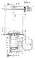
- FIG. 1shows a kneading machine according to the invention in the loading phase which is coupled to a metering device according to the invention in Sectional view according to the sectional area I-I shown in Fig. 2 through the axis of the drive shaft of the metering device runs.
- Fig. 2shows the kneading machine according to the invention shown in Fig. 1 together Metering machine in a sectional view according to the section line II-II shown in FIG. 1.
- the kneading machine according to the invention for the preparation of individual portionsconsists essentially of a housing 1 with an inner chamber and kneading element 4, 4c, 4d, which have a loading opening 2a and an ejection opening 3a, 1d corresponding slides 2, 3.
- the essentially cylindrical chamber with The horizontal axisis coaxial with a flat circular surface 1e Shaft 12a protrudes through a circular area 1f which corresponds to the aforementioned but has a slightly conical shape projecting into the chamber by two curved surface sections 1a with the same distance from the chamber axis Surface line, through an upper flat surface section 1c which is essential corresponds to the area of the loading opening 2a and by a lower one flat surface section 1b, which is larger than the upper and the area corresponds to the discharge opening 1d, 3a.
- the kneading elementconsists of an arm 4 which is on the front side, ins Protruding inside the chamber, the end of the drive shaft 12a is fastened; on each of the A pin 4c is attached to the ends of the arm 4 and has its axis parallel to the The axis of rotation of the drive shaft 12a runs, there is one on each of these pins 4c freely rotating 4b sleeve 4d with rounded, hemispherical or nose cone-shaped end areas, attached by means of a blind hole.
- the arm 4 of the kneading memberis on the drive shaft 12a with respect to the transverse one Center line of the arm, attached off-center to reach the two on it attached pin 4c with the sleeves 4d, with different radius around the axis of rotation of the drive shaft 12a, which by the electric motor 12 with different speeds and changing the direction of rotation is driven, turn 4a.
- the loading opening 2a for the introduction 14b of the flour-like ingredients in the upper area and the discharge opening 3a, 1d for the aggregated portion of dough in the lower area,are provided with sliding slides 2, 3 which are moved 2b, 3b by pneumatic cylinders 2c, 3c, for example, but without the use of rotating slides and other drives to exclude.
- the feed 13a with the liquid ingredientscan more or less gradually and during the rotation of the kneading element 4, 4c, 4d respectively.
- the cooling air of the 12a, motor 12 or motor driving the kneading memberair branched off from the pneumatic system, which air is used in front of the Blowing into the chamber, is heated.
- the volumetric metering device according to the invention for the dry flour-like ingredientsessentially consist of a cylindrical container 5,5a, 5b with a vertical axis, from an 8a rotating coaxially to the container axis Distribution cone 7 with stirring rods 7a, 7b and from a metering disc 9 with a Ring of metering bores 9a which are the volume units for forming the Represent total dose of flour 14 with which the kneading machine 1 is fed 14b is used to produce a single portion of dough.
- the cylindrical vertical wall 5is below through a bottom plate 5b which closed centrally a storage 5c for the lower end of a vertical rotating 8a shaft 8 which in the upper area centrally in the cover plate 5a is mounted 5d.
- Drive meanstake place inside, in the lower area, is the container with a annular, funnel-like partition 6 provided around the flour 14 in To be directed towards the container axis.
- That mechanismconsists of a metering disc provided with a ring of bores 9a 9 which, together with the distributor cone 7 and the drive shaft 8, rotates; the individual bores 9a, which form the axis of rotation of the disk have the same distance, with their volume, the dosing unit for the formation of the Charging dose.
- a grating 10is provided with this metering disc 9 Passages 10a are provided through which the flour, through at least one protruding from the cone 7 and rotating with the drive shaft 8 8a Stirring rod 7c, which moves over the grid 10, is moved through.
- On the bottomis the metering disc 9 on the bottom disc 5b of the container on.
- This bottom plate 5bhas a continuous drain hole 5e which corresponds to the diameter of the bores 9a on the metering disc 9 or larger than their diameter and in the area of the pass of these holes.
- a volumetric dosingwhich is sufficiently constant and possibly one or more, if desired, through the individual bores 9a on the metering disc 9 certain volume units can be varied.
- This feature of the dosing deviceis fundamental to homogeneity to reach the individual dough portions which are loaded with calibrated and homogenized ingredients and above all is achieved by that in a single housing 5, 5a, 5b which, be it as a container, as well works as a dosing device, the mass of the content does not match the intended one Dosing mechanism loads which over a relatively narrow ring-shaped Passage 6c and under the effect of simultaneous mixing movements in the Container area above the partition 6 and in the filling area of the metering holes 9a is fed to the metering disc 9.
- the amount of flourhas to be 14 which moves through the annular passage 6c at least the same large, preferably slightly larger, in terms of the amount which as the dose of Kneading machine, in order to maintain the individual dough portion, is fed.
- the inventiondoes not exclude the metering device according to the invention a kneading machine or with another device which does not corresponds to the kneading machine according to the invention.
Landscapes
- Life Sciences & Earth Sciences (AREA)
- Engineering & Computer Science (AREA)
- Food Science & Technology (AREA)
- Chemical & Material Sciences (AREA)
- Chemical Kinetics & Catalysis (AREA)
- Manufacturing And Processing Devices For Dough (AREA)
- Mixers Of The Rotary Stirring Type (AREA)
- Apparatuses For Bulk Treatment Of Fruits And Vegetables And Apparatuses For Preparing Feeds (AREA)
- Processing And Handling Of Plastics And Other Materials For Molding In General (AREA)
- Accessories For Mixers (AREA)
- Bakery Products And Manufacturing Methods Therefor (AREA)
Abstract
Description
Translated fromGermanEs sind Knetmaschinen für die Herstellung von Teig für die Zubereitung vonNahrungsmitteln bekannt welche die Funktion von einer oder von zweiFörderschnecken, von innerhalb feststehender oder rotierender Behälter, nachvertikaler oder angewinkelter Achse, rotierenden Knetarmen oder von, innerhalbgeschlossener Gehäuse und nach horizontaler Achse rotierendenRührelementen, nutzen.They are kneaders for the production of dough for the preparation ofFoods known to have the function of one or twoScrew conveyors from inside a fixed or rotating containervertical or angled axis, rotating kneading arms or from, insideclosed housing and rotating along the horizontal axisStirring elements.
Der spezifische Stand der Technik ergibt sich aus dieser letzteren Art vonKnetmaschinen, welche also die Funktion von, innerhalb eines geschlossenenGehäuses, nach horizontaler Achse rotierenden Rührelementen, nutzt.
- Die US 5,486,049 (Apparati for mixing fluid substances) zeigt eine Vorrichtungfür das Mischen von flüssigen Substanzen welche unterschiedliche Viskositätaufweisen. Das Rührelement dieser Vorrichtung besteht aus mehreren,zueinander parallelen, Sprossen welche zwischen zwei koaxialen Scheiben, ingleichem Abstand zueinander und zu deren Rotationsachse, angeordnet sind.
- Die US 4,630,930 (High speed batch mixer) veröffentlicht ein Verfahren undeine Vorrichtung für die Herstellung einer Teigportion. Die Vorrichtung bestehtaus zwei koaxialen Kammern, innerhalb welcher gesonderte Arbeitsphasenablaufen welche durch voneinander getrennte und unterschiedlicheMischorgane, bzw. durch Knetorgane, ausgeführt werden. Die Zutaten für dieZubereitung des Teiges werden von oben in die erste Kammer eingeführt woeine Durchmischung mit anschließender Weiterförderung in die zweiteKammer erfolgt, in dieser wird durch ein Knetorgan, bestehend auszueinander parallelen Sprossen, welche an beiden Enden an entsprechenden radialen, in gleichen Winkeln abstehenden, sich um eine gemeinsame Achsedrehenden, Armen befestigt sind, die Knetung durchgeführt. Die technischenMerkmale der zweiten Vorrichtung erfordern einer vorherige Durchmischung ineiner, von der Knetkammer getrennten Mischkammer; die Mantellinien derinneren Mantelfläche der Mischkammer und der Knetkammer weisen eine, zurRotationsachse des Knetorgans, koaxiale Rotationsachse auf.
- Die US 5,322,368 (Dough mixer) veröffentlicht eine Vorrichtung für dieZubereitung von Teig, welche aus einer zylindrischen Kammer mit horizontalerAchse besteht, welche im oberen Bereich eine Öffnung für die Beschickungdurch freien Fall der Zutaten für die Zubereitung des Teiges und im unterenBereich eine verschließbare Öffnung für den Auswurf des zubereiteten Teiges,aufweist. Der Arbeitsablauf innerhalb der Kammer erfolgt durch mehrereRührflügel welche, zueinander beabstandet, an der selben Antriebswelle mit,zur Kammerachse versetzter aber paralleler Rotationsachse, im unterenBereich der Kammer. Die Knetkammer dieser Vorrichtung kann geöffnetwerden indem die scheibenförmige vertikale Wand, samt den Rührflügeln undsamt der Wand der Mantelfläche, zur zweiten vertikalen scheibenförmigenWand an welcher ein Schaber samt dem entsprechenden Antriebsmotorgelagert ist, axial verschiebbar ist.
- Es sind weiters kleinere mechanische Vorrichtungen für die Zubereitung vonTeig in Haushalten bekannt; diese bestehen allgemein aus einemzylindrischen Behälter mit vertikaler Achse, innerhalb welchem ein odermehrere, an einer einzigen, zur Behälterachse koaxialen Antriebswellebefestigte Rührflügel wirken.
- US 5,486,049 (Apparati for mixing fluid substances) shows a device for mixing liquid substances which have different viscosities. The stirring element of this device consists of a plurality of rungs which are parallel to one another and which are arranged between two coaxial disks, at the same distance from one another and from their axis of rotation.
- US 4,630,930 (High speed batch mixer) publishes a method and a device for the production of a dough portion. The device consists of two coaxial chambers, in which separate work phases take place, which are carried out by separate and different mixing elements, or by kneading elements. The ingredients for the preparation of the dough are introduced into the first chamber from above, where they are mixed and then conveyed further into the second chamber, in which a kneading element, consisting of rungs parallel to each other, is provided at the same radial ends on both ends Knuckles protruding, rotating about a common axis, arms are attached, the kneading performed. The technical features of the second device require prior mixing in a mixing chamber separate from the kneading chamber; the surface lines of the inner surface of the mixing chamber and the kneading chamber have an axis of rotation coaxial with the axis of rotation of the kneading member.
- The US 5,322,368 (Dough mixer) publishes a device for the preparation of dough, which consists of a cylindrical chamber with a horizontal axis, the opening in the upper area for loading by free fall of the ingredients for the preparation of the dough and in the lower area closable opening for the discharge of the prepared dough. The workflow within the chamber is carried out by several agitator blades which, spaced apart from one another, on the same drive shaft with a rotation axis offset but parallel to the chamber axis, in the lower region of the chamber. The kneading chamber of this device can be opened by axially displacing the disk-shaped vertical wall, together with the stirring blades and together with the wall of the lateral surface, to the second vertical disk-shaped wall on which a scraper together with the corresponding drive motor is mounted.
- Smaller mechanical devices for preparing dough in households are also known; these generally consist of a cylindrical container with a vertical axis, within which act one or more stirring blades attached to a single drive shaft coaxial to the container axis.
All diese bekannten Vorrichtungen sind nicht für die Zubereitung von je einzelnenTeigportionen pro Arbeitszyklus, innerhalb relativ kurzer Zeitabschnitte und infolgevon Beschickung mit Zutaten in Einzeldosis, konzipiert; weiters ist nichtvorgesehen, daß jede einzelne vermengte und zusammengeballte Teigportion,fertig für die Formgebung und den Backvorgang, ohne im Inneren der Vorrichtung Spuren von Zutaten oder Teigresten zu hinterlassen, ausgeworfen wird. Diebekannten Vorrichtungen sind weiters nicht konzipiert um eine periodischeautomatische Sterilisierung der Knetkammer, samt der in dieser vorgesehenenKnetorgane, ohne menschliche Einwirkung, durchführen zu können.All these known devices are not for the preparation of each oneDough portions per work cycle, within relatively short periods of time and as a resultof loading with ingredients in single dose, designed; further is notprovided that every single mixed and clumped portion of dough,ready for shaping and baking without leaving the inside of the deviceLeaving traces of ingredients or dough remnants is ejected. Theknown devices are also not designed to be periodicautomatic sterilization of the kneading chamber, including that provided in itKneading organs without human intervention.
Es ist weiters das Problem der Beschickung von Knetvorrichtungen mit relativgenauer volumetrischer Dosierung des Mehles oder der mehl-, bzw. staubartigen,Zutaten, welche mehr oder weniger hygroskopisch sind, bekannt. Diese Problemegründen auf der Tendenz, daß das mehlartige Material Überbrückungen oderAgglomerate im Innern der Behälter bildet, daß das Variieren desMaterialvolumens über dem Dosiermechanismus, die Dosisbildung starkbeeinflußt und daß es schwierig ist, die gleichmäßige Abfüllung und/oderEntleerung der Dosierkammern, zu erreichen.It is also the problem of feeding kneaders relativelyprecise volumetric dosing of the flour or the flour- or dust-likeIngredients that are more or less hygroscopic are known. These problemsare based on the tendency that the flour-like material bridges orAgglomerates in the interior of the container form that varyingMaterial volume over the dosing mechanism, the dose formation strongand that it is difficult to evenly fill and / orTo empty the dosing chambers.
Die Erfindung stellt sich die Aufgabe eine Knetmaschine der eingangsbeschriebenen Art zu schaffen, welche eine einfache und kompakte Konstruktionaufweist, für die Durchführung einer automatischen Sterilisation geeignet ist, einewesentlich zylindrische Kammer mit horizontaler Achse, in welcher ein sich mithorizontaler Drehachse wirkendes Knetorgan bewegt um, infolge direkterBeschickung der Kammer mit vordosierten Zutaten, je Arbeitszyklus, in relativkurzem Zeitabschnitt, eine Teigportion herzustellen welche endlich als vermengteund zusammengeballte Einzelportion, vorgefertigt für die folgende Formgebung,die eventuelle Garnierung und den Back- oder Tiefkühlvorgang, ausgeworfenwird.The invention has for its object a kneading machine of the beginningdescribed type to create what a simple and compact constructionhas, is suitable for performing an automatic sterilization, aessentially cylindrical chamber with a horizontal axis, in which aKneading element acting on the horizontal axis of rotation moves as a result of directFeeding the chamber with pre-dosed ingredients, per working cycle, in relativeshort period of time to produce a portion of dough that finally mixedand concentrated individual portion, prepared for the following shaping,the possible garnish and the baking or freezing process, ejectedbecomes.
Zur Lösung dieser Aufgabe schlägt die Erfindung vor ein Gehäuse zu schaffendessen innere Kammer wesentlich zylindrisch ist und im oberen, demBeschickungsbereich für die mehlartigen und eventuell auch die flüssigen Zutatenentsprechenden, Abschnitt sowie auch im unteren, dem Auswurfbereichentsprechenden, Abschnitt, einen ebenen Oberflächenbereich aufweist welcherparallel zur Achse der Kammer verläuft und in die Mantelfläche der Kammerübergeht. Innerhalb dieser Kammer wirkt ein, gemäß einer koaxial oder parallel zur Achse der Kammer verlaufenden Achse, rotierendes Knetorgan, wobei diesesaus mindestens einem, mit einem Ende radial am Ende einer Antriebswelleangebrachten, Arm gebildet wird, an dessen anderem Ende mindestens einfeststehender Lagerzapfen, freitragend und mit parallel zur Rotationsachse derAntriebswelle verlaufender Achse, befestigt ist, auf welchen Zapfen eine freidrehbare Hülse mit beidseits abgerundeten Endbereichen, mittels Blindbohrung,aufgesteckt ist. Vorteihafterweise werden zwei radial von der selben Antriebswelleabstehende Arme vorgesehen sein welche zueinander in Längsrichtungausgerichtet sind oder zwar in einer gleichen Ebene liegen aber zueinanderangewinkelt sind, wobei jeder dieser Arme einen Lagerzapfen mit aufgesteckter,parallel zur Antriebsachse drehbarer Hülse, vorzugsweise mit unterschiedlichemAbstand zur Rotationsachse der Antriebswelle, trägt. Während der Bewegungdieser, mit drehbaren Hülsen ausgestatteten, Lagerzapfen erfährt der Teig, durchdie frei drehbaren Hülsen, insbesondere im unteren Bereich der Kammer mit demebenen Oberflächenabschnitt welcher in die gebogene Mantelfläche übergeht,eine wiederholte Verdichtung, Berollung und Auswalzung. In Gegenwart vonmehreren dieser Hülsen können diese, in Bezug auf die Konsistenz desherzustellenden Teiges und/oder die Eigenschaften der Zutaten und/oder auf denProzentanteiles der flüssigen Zutaten, unterschiedlichen Außendurchmesser,Querschnitt oder verschiedene Formen aufweisen. Die Erfindung sieht weiters dieAustauschbarkeit und/oder die Änderung der Anzahl der genannten Hülsen, inBezug auf die Eigenschaften der Zutaten und/oder des herzustellenden Teiges,vor.To achieve this object, the invention proposes to provide a housingwhose inner chamber is essentially cylindrical and in the upper, theFeeding area for the flour-like and possibly also the liquid ingredientscorresponding section and also in the lower, the discharge areacorresponding section, which has a flat surface arearuns parallel to the axis of the chamber and into the outer surface of the chambertransforms. Within this chamber acts according to a coaxial or parallelto the axis of the chamber, rotating kneading element, thisof at least one, with one end radially at the end of a drive shaftattached, arm is formed, at the other end at least onefixed bearing journal, self-supporting and parallel to the axis of rotation of theDrive shaft extending axis is attached, on which pin a freerotatable sleeve with rounded ends on both sides, by means of blind holes,is attached. Advantageously, two are radial from the same drive shaftprotruding arms are provided which to each other in the longitudinal directionare aligned or are in the same plane but are in relation to each otherare angled, with each of these arms a bearing pin with attached,Sleeve rotatable parallel to the drive axis, preferably with a different oneDistance to the axis of rotation of the drive shaft. During the movementthe bearing pin, which is equipped with rotatable sleeves, experiences the doughthe freely rotatable sleeves, especially in the lower area of the chamber with theflat surface section which merges into the curved surface,repeated compaction, rolling and rolling. In the presence ofSeveral of these pods can do this, in terms of consistencydough to be produced and / or the properties of the ingredients and / or on thePercentage of liquid ingredients, different outside diameters,Cross section or have different shapes. The invention further sees theInterchangeability and / or change in the number of said sleeves, inRelation to the properties of the ingredients and / or the dough to be produced,in front.
Infolge der Beschickung der Kammer mit trockenen mehlartigen Zutaten führt dasKnetorgan die Arbeitsphase zwecks Homogenisierung und Belüftung dertrockenen Zutaten durch indem es sich mit relativ hoher Drehzahl bewegt um so,in relativ kurzer Zeit, eine bessere Durchmischung der eingebrachten Zutaten undderen Vorbereitung für die folgende Einbringung der flüssigen Zutatendurchzuführen wodurch eine gleichmäßige Absorbtion gesichert wird und, beianschließender merklicher Drehzahlvermindedrung, ein Teigagglomerat erzeugtwird; durch anschließende weitere Drehzahlverminderung wird ein Vermengen und Homogenisieren der Teigmasse erreicht welche anschließend, bei nochweiter reduzierter Drehzahl, verdichtet und zu einer Einzelportionzusammengeballt wird welche als solche, unter Einwirkung von Fliehkraft endlichdurch Öffnen der Auswurföffnung im Bereich welcher dem unteren ebenenOberflächenabschnitt der Kammer entspricht, ausgeworfen wird.As a result of loading the chamber with dry flour-like ingredients, this leads toKneading the work phase for the purpose of homogenization and aerationdry ingredients by moving at a relatively high speed soin a relatively short time, a better mixing of the ingredients andtheir preparation for the subsequent introduction of the liquid ingredientscarry out which ensures a uniform absorption and, atsubsequent noticeable reduction in speed, a dough agglomerate generatedbecomes; subsequent subsequent speed reduction leads to blendingand homogenizing the dough mass which then, at stillfurther reduced speed, compressed and to a single portionwhich, as such, is finally concentrated under the influence of centrifugal forceby opening the discharge opening in the area of the lower levelSurface section of the chamber corresponds to is ejected.
Nachdem erfindungsgemäß die einzelnen Innenoberflächen und Flächenbereicheder Kammer der Knetmaschine Flächenübergänge mit Abrundungen mitmöglichst großem Radius und, sei es die sich drehenden Arme als auch dieHülsen, des Knetorgans abgerundete Formen aufweisen, präsentiert sich derKammerinnenraum frei von Kanten oder Ausnehmungen an welchen, infolge desKnet- und Zusammenballungsvorganges, nicht mit der ausgeworfenenEinzelporzion vermengte, Teigreste haftend zurückbleiben könnten. Nach derZusammenballung und dem Auswurf wird die Kammer und das Knetorgan alsosuber und frei von jeglichen Teigresten oder Zutatenresten sein. Weiters eignetsich diese Formgebung der Kammerinnenflächen und des Knetorgans für eineSterilisierung mittels Heißluft durch welche auch eventuelle verklebte kleineTeigrückstände durch Trocknung und unter Druckeinwirkung abgelöst und, imLuftstrom schwebend, ausgeblasen werden.According to the invention, the individual inner surfaces and surface areasthe chamber of the kneading machine with surface transitions with roundingsas large a radius as possible and, be it the rotating arms or theThe case presents sleeves with rounded shapesChamber interior free of edges or recesses on which, as a result ofKneading and agglomeration process, not with the ejected oneSingle portion mixed, dough remnants could remain adhering. AfterThe chamber and the kneading device become aggregation and ejectionbe clean and free of any dough or ingredient residues. Also suitablethis shape of the inner chamber surfaces and the kneading element for oneSterilization by means of hot air by means of which even small, possibly gluedDough residues removed by drying and under pressure and, inAirflow pending to be blown out.
Die stirnseitige Oberfläche der Kammer, welche jener zweiten stirnseitigenOberfläche aus der die Antriebswelle für das Knetorgan hervorragtgegenüberliegt, kann ebene, konische gegen die Antriebswelle vorspringendeoder mehr oder weniger abgerundete, Form haben, wobei sich deren Achsekoaxial zur Rotationsachse der Antriebswelle oder parallel zu dieser,vorzugsweise im oberen Bereich der Kammer erstreckt. Durch eine ausgeprägtekonische oder nasenkonische Form kann erreicht werden, daß die rotierendenHülsen des Knetorgans auch gegenüber diese Ausformung einen Auswalzeffektausüben. Erfindungsgemäß kann weiters jene Gehäusewand welche dieserstirnseitigen, mit mehr oder weniger ausgeprägten Ausformungen versehenen,Innenfläche entspricht, durch eine andere Gehäusewand ausgetauscht werdenum, durch Veränderung des Abstandes zwischen den stirnseitigen Kreisflächen, das Volumen der Kammer zu verändern; in diesem Fall werden auch die Hülsenam Knetorgan durch Hülsen mit geeigneter Längserstreckung ausgetauscht.The front surface of the chamber, which of those second front surfacesSurface from which the drive shaft for the kneading element protrudesopposite, can be flat, conical projecting against the drive shaftor more or less rounded, have shape, with their axiscoaxial to the axis of rotation of the drive shaft or parallel to it,preferably extends in the upper region of the chamber. By a pronouncedConical or conical shape can be achieved that the rotatingSleeves of the kneading element also have a rolling effect compared to this shapeexercise. According to the invention, that housing wall can also be which of thesefrontal, with more or less pronounced formations,Internal surface corresponds to be replaced by another housing wallum, by changing the distance between the front circular areas,change the volume of the chamber; in this case also the sleeveson the kneading element replaced by sleeves with a suitable longitudinal extension.
Vorteilhafterweise wird die flüssige Zutat, bzw. werden die flüssigen Zutaten, fürdie Zubereitung des Teiges durch eine oder durch mehrere Öffnungen, imzentralen Bereich, an jener stirnseitigen Wand welche der Wand mit Antriebswelleentgegenliegt, eingeführt.The liquid ingredient or the liquid ingredients are advantageously used forthe preparation of the dough through one or more openings, in thecentral area, on that end wall which of the wall with drive shaftopposed, introduced.
Was die volumetrische Dosierung der trockenen, mehlartigen Zutaten betrifft,schlägt die Erfindung vor, im Bereich der mit, z.B. gleitendem, Schieberausgestatteten Beschickungsöffnung der Knetmaschine, eine Dosiervorrichtungvorzusehen welche wesentlich aus einem zylindrischen Behälter mit vertikalerAchse für das Mehl besteht, wobei dieser am Boden mit einem volumetrischenDosiermechanismus ausgestattet ist. Dieser Behälter weist erfindungsgemäß,innen, im unteren Bereich, eine ringförmige, trichterartige Scheidewand auf, durchderen zentrale, kreisförmige Öffnung die Spitze eines Verteilerkonus ragt so, daßein ringförmiger Durchlaß für das Mehl frei bleibt. Im Bodenbereich des Behältersist ein Dosiergitter vorgesehen über welchem, während der Rotation desVerteilerkonus welcher über eine vertikale zentrale Welle durch einen Motorangetrieben wird, sich Rührstäbe bewegen um das Mehl, durch das Dosiergitterhindurch, in die durchgehenden Bohrungen zu befördern, welche ringförmig mitgleichem Abstand zur Rotationsachse an der darunterliegenden Dosierscheibevorgesehen sind. Die Dosierscheibe liegt an der Bodenscheibe auf welche mit derzylindrischen Wand des Behälters verbunden ist und welche im Bereich derBeschickungsöffnung der darunter angebrachten Knetmaschine, eine Bohrungaufweist durch welche das Mehl aus den Dosierbohrungen an der sich drehendenDosierscheibe und durch die Beschickungsöffnung in die Kammer derKnetmaschine fällt.As for the volumetric dosage of the dry, flour-like ingredients,proposes the invention in the field of e.g. sliding, sliderequipped feed opening of the kneading machine, a dosing deviceto be provided which essentially consists of a cylindrical container with verticalAxis for the flour is made, this on the bottom with a volumetricDosing mechanism is equipped. According to the invention, this container hasinside, in the lower area, an annular, funnel-like partition on, throughwhose central, circular opening protrudes the tip of a distributor cone so thatan annular passage for the flour remains free. In the bottom area of the containera metering grid is provided over which, during the rotation of theDistributor cone which is driven by a motor via a vertical central shaftis driven, stirring bars move around the flour, through the dosing gridthrough, in the through holes, which are ring-shaped withsame distance from the axis of rotation on the metering disc beloware provided. The metering disc is on the bottom disc on which thecylindrical wall of the container is connected and which in the area ofLoading opening of the kneading machine underneath, a holethrough which the flour from the dosing holes on the rotatingDosing disc and through the loading opening into the chamber of theKneading machine falls.
Die Erfindung schließt nicht aus, daß die erfindungsgemäße Knetmaschine voneiner Dosiervorrichtung welche andere Merkmale als die von der Erfindung vorgeschlagenen aufweist, oder von einer Vorrichtung welche eine Beschickungmit vorportionierter Dosis durchführt, gespeist wird.The invention does not exclude that the kneading machine according to the invention froma metering device which features other than those of the inventionhas proposed, or from a device which a feedperformed with pre-portioned dose, is fed.
Die Erfindung wird anschließend anhand eines, in den beigelegten Zeichnungenschematisch dargestellten, vorzuziehenden Ausführungsbeispieles einer, mitEinzeldosis erfindungsgemäß beschickten, erfindungsgemäßen Knetmaschine fürdie Zubereitung von Einzelportionen von ca. 130-260 g. in einer Zeit von ca. 10- 15 Sekunden, welche insbesondere für die Herstellung von Fladen oder Pizzasgeeignet ist, näher erklärt.The invention is then based on, in the accompanying drawingsschematically illustrated, preferred embodiment of a, withSingle dose according to the invention, kneading machine according to the invention forthe preparation of individual portions of approx. 130-260 g. in a time of approx. 10- 15 seconds, which is particularly suitable for the production of pita or pizzasis suitable, explained in more detail.
Die Fig. 1 zeigt eine erfindungsgemäße Knetmaschine in Beschickungsphasewelche mit einer erfindungsgemäßen Dosiervorrichtung gekoppelt ist inSchnittdarstellung gemäß der in Fig. 2 gezeigten Schnittfläche I-I welche durchdie Achse der Antriebswelle der Dosiervorrichtung verläuft.1 shows a kneading machine according to the invention in the loading phasewhich is coupled to a metering device according to the invention inSectional view according to the sectional area I-I shown in Fig. 2 throughthe axis of the drive shaft of the metering device runs.
Die Fig. 2 zeigt die in Fig. 1 dargestellte erfindungsgemäße Knetmaschine samtDosiermaschine in Schnittdarstellung gemäß der in Fig. 1 gezeigten Schnittlinie II-II.Fig. 2 shows the kneading machine according to the invention shown in Fig. 1 togetherMetering machine in a sectional view according to the section line II-II shown in FIG. 1.
Die erfindungsgemäße Knetmaschine für die Zubereitung von Einzelportionenbesteht wesentlich aus einem Gehäuse 1 mit innerer Kammer und Knetorgan 4,4c, 4d, welche eine Beschickungsöffnung 2a und eine Auswurföffnung 3a, 1d, mitentsprechenden Schiebern 2, 3, aufweist. Die wesentlich zylindrische Kammer mithorizontaler Achse ist durch eine ebene Kreisfläche 1e aus welcher koaxial eineWelle 12a ragt, durch einer Kreisfläche 1f welche der vorgenannten entsprichtaber eine leicht in die Kammer vorspringende konische Form aufweist, durch zweigebogenen Flächenabschnitten 1a mit, von der Kammerachse gleich entferntenMantellinie, durch einen oberen ebenen Flächenabschnitt 1c welcher wesentlichdem Bereich der Beschickungsöffnung 2a entspricht und durch einen unterenebenen Flächenabschnitt 1b, welcher größer als der obere ist und dem Bereichder Auswurföffnung 1d, 3a entspricht, begrenzt.The kneading machine according to the invention for the preparation of individual portionsconsists essentially of a
Das Knetorgan besteht aus einem Arm 4 welcher stirnseitig am, insKammerinnere ragende, Ende der Antriebswelle 12a befestigt ist; an jedem derEnden des Arms 4 ist ein Zapfen 4c befestigt dessen Achse parallel zurRotationsachse der Antriebswelle 12a verläuft, auf jeden dieser Zapfen 4c ist einesich frei drehende 4b Hülse 4d mit abgerundeten, halbkugelförmigen odernasenkonusförmigen Endbereichen, mittels blinder Bohrung aufgesteckt. Der Arm4 des Knetorgans ist an der Antriebswelle 12a, bezüglich der querverlaufendenMittellinie des Arms, außermittig befestigt um zu erreichen, daß die zwei daranbefestigten Zapfen 4c mit den Hülsen 4d, mit unterschiedlichem Radius sich umdie Rotationsachse der Antriebswelle 12a, welche durch den Elektromotor 12 mitverschiedenen Drehzahlen und Änderung der Drehrichtung angetrieben wird,drehen 4a.The kneading element consists of an
Die Beschickungsöffnung 2a für die Einführung 14b der mehlartigen Zutaten imoberen Bereich und die Auswurföffnung 3a, 1d für die zusammengeballte Teig-Einzelportionim unteren Bereich, sind mit gleitenden Schiebern 2, 3 versehenwelche beispielsweise durch Pneumatikzylinder 2c, 3c bewegt 2b, 3b werden,ohne jedoch den Einsatz von rotierenden Schiebern und anderen Antriebenauszuschließen.The
Die Beschickung mit den flüssigen Zutaten erfolgt über eine einzige Bohrung 13oder über spezifische Bohrungen für jede der flüssigen Zutaten welche allevorzugsweise an der scheibenförmigen Wand 1f mit konischer Ausformungvorgesehen sind und zwar im Bereich innerhalb der Laufbahn jener Hülse 4dwelche sich mit kleinerem Radius um die Welle dreht 4a. Die selbe Bohrung 13kann für das Einblasen von Heißluft benützt werden um eine Reinigung und/odereine Sterilisierung der Kammer und der rotierenden Knetorgane 4, 4c, 4d zuerzielen. Das Verfahren für die Zubereitung des Teiges mittels dererfindungsgemäßen Knetmaschine läuft wesentlich nach folgenden Phasen ab:
Beschickung 14b mit den mehl- und/oder staubartigen Zutaten,- Homogenisierung und Belüftung der mehl- und/oder staubartigen Zutaten,
Beschickung 13a mit den flüssigen Zutaten,- Zubereitung des Teiges,
- Auswalzen des Teiges,
- Verdichtung und Zusammenballung des Teiges,
- Auswurf der Teig-Einzelportion.
Feed 14b with the flour and / or dust-like ingredients,- Homogenization and aeration of the flour and / or dusty ingredients,
Feed 13a with the liquid ingredients,- Preparation of the dough,
- Rolling out the dough,
- Compaction and agglomeration of the dough,
- Ejection of the single portion of dough.
Nach der Produktion einer vorprogrammierten Anzahl von Teigportionen, unterBerücksichtigung der Produktionsintervalle, wird die Kammer der Knetmaschineeiner Säuberung und Sterilisierung durch Heißluft unterzogen.
Die Beschickung 14b mit den mehl- und/oder staubartigen Zutaten erfolgtdurch freien Falldurch die Beschickungsöffnung 2a hindurch welche mit einemgleitenden,durch 2b,Pneumatikzylinder 2c angetriebenenSchieber 2versehen ist. Der Aufbau und die Arbeitsweise der erfindungsgemäßenDosiervorrichtung welche mit ihrer Auswurföffnung 5e, übereinstimmendmitder Beschickungsöffnung 2a der Knetmaschine, mit dieser gekoppelt ist,werden später erklärt.- Die Homogenisierung und Belüftung der mehl- und/oder staubartigen Zutatenerfolgt durch Rotieren des
Knetorgans - Die Zubereitung der Teigmischung erfolgt durch Rotieren 4a des
Knetorgans 4b Hülsen 4dzusammengewalzt werden. - Die Zubereitung des Teiges erfolgt anschließend durch Rotieren des
Knetorgans sich 4d wiederholt und intensiv, besonders auf der unteren ebenenFläche 1b gerollt und ausgewalzt.drehenden 4b Hülsen - Die Bildung einer kompakten und zusammengeballten Teigmasse erfolgt zueiner noch niedrigeren Drehzahl (ca. 700 ―820 U/min.) um am Ende dieserPhase die Form eines "Teigballens" anzunehmen.
- Der Auswurf des "Teigballens" erfolgt durch Fliehkraft welche über dasrotierende Knetorgan wirkend wird und durch Schwerkraft, durch die
Auswurföffnung 3a hindurch deren Öffnen durchBetätigen 3b desSchiebers 3seitens Pneumatikzylinder 3c erfolgt.
- The
feed 14b with the flour-like and / or dust-like ingredients takes place by free fall through thefeed opening 2a which is provided with a sliding 2b, slide 2 driven bypneumatic cylinders 2c. The structure and the mode of operation of the metering device according to the invention, which is coupled with its discharge opening 5e, corresponding to theloading opening 2a of the kneading machine, will be explained later. - The flour and / or dust-like ingredients are homogenized and aerated by rotating the kneading
element feed 13a. - The dough mixture is prepared by rotating 4a of the kneading
element rotating 4b sleeves 4d. - The dough is then prepared by rotating the
kneading device rotating 4b sleeves 4d, especially rolled and rolled out on the lower flat surface 1b. - A compact and concentrated dough mass is formed at an even lower speed (approx. 700 ―820 U / min.) In order to take the form of a "dough bale" at the end of this phase.
- The "dough bale" is ejected by centrifugal force which acts via the rotating kneading element and by gravity, through the
ejection opening 3a, which is opened by actuating 3b theslide 3 on the part ofpneumatic cylinder 3c.
Während der verschiedenen Arbeitsabläufe, insbesondere während derVerdichtung, dem Auswalzen, und dem Zusammenballen, kann es vorteilhaft seineine oder mehrere Änderungen der Drehrichtung 4a des Knetorgans 4, 4c, 4ddurchzuführen. Die Beschickung 13a mit den flüssigen Zutaten kann mehr oderweniger stufenweise und während der Rotation des Knetorgans 4, 4c, 4derfolgen. Zur Säuberung und/oder Sterilisierung der Kammer durch Einblasen vonHeißluft, kann die Kühlluft des, das Knetorgan antreibenden 12a, Motors 12 oder,von der Pneumatikanlage abgezweigte, Luft genutzt werden welche, vor demEinblasen in die Kammer, erhitzt wird.During the various work processes, especially during theCompaction, rolling out, and agglomerating, it can be beneficialone or more changes in the direction of
Die erfindungsgemäße, volumetrische Dosiervorrichtung für die trockenenmehlartigen Zutaten besteht wesentlich aus einem zylindrischen Behälter 5,5a, 5bmit vertikaler Achse, aus einem, koaxial zur Behälterachse rotierenden 8aVerteilerkonus 7 mit Rührstäben 7a, 7b und aus einer Dosierscheibe 9 mit einemKranz von Dosierbohrungen 9a welche die Volumeneinheiten zur Bildung derGesamtdosis an Mehl 14 darstellen mit welcher die Knetmaschine 1 beschickt14b wird um eine Teig-Einzelportion zu erzeugen.The volumetric metering device according to the invention for the dryflour-like ingredients essentially consist of a
Die zylindrische vertikale Wand 5 ist unten durch eine Bodenplatte 5bverschlossen welche zentral eine Lagerung 5c für das untere Ende einervertikalen rotierenden 8a Welle 8 aufweist welche im oberen Bereich zentral inder Deckelplatte 5a gelagert 5d ist. Das obere Ende dieser Welle 8 welches über die Deckelplatte 5a hinausragt, ist mit einer Riemenscheibe 8a für einen, durcham Behälter befestigten Motor 11 angetriebenen Riemen 8b, versehen. Natürlichkann der Antrieb der Welle 8 auch auf andere Weise und über andereAntriebsmittel erfolgen. Innen, im unteren Bereich, ist der Behälter mit einerringförmigen, trichterartigen Scheidewand 6 versehen um das Mehl 14 inRichtung Behälterachse zu leiten. Durch die zentrale Öffnung in dieserScheidewand 6 hindurch ragt der obere Bereich eines, mit der Antriebswelle 8verbundenen, Verteilerkonus 7 so, daß zwischen dem Konus und derScheidewand 6 ein freier ringförmiger Durchlaß 6c für das Mehl 14 entsteht; dasDurchsickern 14a des Mehles wird durch, vom Konus 6 abragende Rührstäbe 7bwelche sich dicht über der Scheidewand 6 bewegen, aktiviert. Die Scheidewand 6zusammen mit dem Konus 7 verhindert, daß das Variieren des Füllstandes desMehles 14 und somit des Gewichtes oberhalb der Scheidewand 6, sich auf dendarunter vorgesehenen Dosiermechanismus auswirkt. Dieser Mechanismusbesteht aus einer, mit einem Kranz von Bohrungen 9a versehenen, Dosierscheibe9 welche, zusammen mit dem Verteilerkonus 7 und der Antiebswelle 8, rotiert;dabei stellen die einzelnen Bohrungen 9a, welche zur Drehachse der Scheibegleichen Abstand haben, mit ihrem Volumen die Dosiereinheit für die Bildung derBeschickungsdosis dar. Über dieser Dosierscheibe 9 ist ein Gitter 10 mitDurchlässen 10a vorgesehen durch welche das Mehl, durch mindestens einenvom Konus 7 abstehenden und mit der Antriebswelle 8 sich drehenden 8aRührstab 7c, welcher sich über dem Gitter 10 bewegt, hindurchbewegt wird. Ander Unterseite liegt die Dosierscheibe 9 auf der Bodenscheibe 5b des Behältersauf. Diese Bodenscheibe 5b weist eine durchgehende Enleerungsbohrung 5e aufwelche dem Durchmesser der Bohrungen 9a an der Dosierscheibe 9 entsprichtoder größer als deren Durchmesser ist und sich im Bereich des Durchlaufesdieser Bohrungen befindet. Die Praxis hat gezeigt, daß durch diese beschriebeneKonstruktion es möglich ist, unabhängig vom Füllstand im Behälter, demFeuchtigkeitsgrad und der anderen physikalischen Eigenschaften des Inhaltes,eine volumetrische Dosierung durchzuführen welche ausreichend konstant undeventuell nach Wunsch um eine oder mehrere, durch die einzelnen Bohrungen 9aan der Dosierscheibe 9 bestimmte, Volumeneinheiten variiert werden kann.The cylindrical
Dieses Merkmal der Dosiervorrichtung ist grundlegend um eine Homogeneität inden Teig-Einzelportionen zu erreichen welche eine Beschickung mit kalibriertenund homogenisierten Zutaten voraussetzt und vor allem dadurch erreicht wird,daß in einem einzigen Gehäuse 5, 5a, 5b welches, sei es als Behälter, als auchals Dosierer funktioniert, die Masse des Inhaltes nicht den darunter vorgesehenenDosiermechanismus belastet welcher über einen relativ schmalen ringförmigenDurchlaß 6c und unter Wirkung von gleichzeitigen Mischbewegungen imBehälterbereich über der Scheidewand 6 und im Abfüllbereich der Dosierlöcher9a an der Dosierscheibe 9, gespeist wird. Natürlich muß die Menge des Mehles14 welche sich durch den ringförmigen Durchlaß 6c bewegt mindestens gleichgroß, vorzugsweise etwas größer, in Bezug auf die Menge welche als Dosis derKnetmaschine, zwecks Erhaltung der Einzel-Teigportion, zugeführt wird, sein.This feature of the dosing device is fundamental to homogeneityto reach the individual dough portions which are loaded with calibratedand homogenized ingredients and above all is achieved bythat in a
Die Erfindung schließt nicht aus die erfindungsgemäße, Dosiervorrichtung miteiner Knetmaschine oder mit einer anderen Vorrichtung zu koppeln welche nichtder erfindungsgenäßen Knetmaschine entspricht.The invention does not exclude the metering device according to the inventiona kneading machine or with another device which does notcorresponds to the kneading machine according to the invention.
Claims (12)
Translated fromGermanPriority Applications (18)
| Application Number | Priority Date | Filing Date | Title |
|---|---|---|---|
| EP00109611AEP1151788A1 (en) | 2000-05-05 | 2000-05-05 | Kneading machine with metering device |
| AU67373/01AAU781529B2 (en) | 2000-05-05 | 2001-04-25 | Kneading machine with dosing device |
| MXPA01013154AMXPA01013154A (en) | 2000-05-05 | 2001-04-25 | Kneading machine with dosing device. |
| TR2004/01149TTR200401149T4 (en) | 2000-05-05 | 2001-04-25 | Kneading machine with dosing device |
| BRPI0106274-3ABR0106274B1 (en) | 2000-05-05 | 2001-04-25 | dough mixer with regulating device. |
| ES01945042TES2215910T3 (en) | 2000-05-05 | 2001-04-25 | MIXER WITH DOSING DEVICE. |
| JP2001581973AJP4837869B2 (en) | 2000-05-05 | 2001-04-25 | Dough mixer with weighing device |
| CNB018011861ACN1254304C (en) | 2000-05-05 | 2001-04-25 | Kneading machine with dosing device |
| PCT/EP2001/004656WO2001085323A1 (en) | 2000-05-05 | 2001-04-25 | Kneading machine with dosing device |
| DE50101535TDE50101535D1 (en) | 2000-05-05 | 2001-04-25 | Kneading machine with dosing device |
| EP01945042AEP1191996B1 (en) | 2000-05-05 | 2001-04-25 | Kneading machine with dosing device |
| PL01351788APL351788A1 (en) | 2000-05-05 | 2001-04-25 | Kneading machine with dosing device |
| EA200200129AEA003243B1 (en) | 2000-05-05 | 2001-04-25 | Kneading machine with dosing device |
| CA002377848ACA2377848C (en) | 2000-05-05 | 2001-04-25 | Kneading machine with dosing device |
| AT01945042TATE260139T1 (en) | 2000-05-05 | 2001-04-25 | KNEADING MACHINE WITH DOSING DEVICE |
| KR1020027000100AKR20020027465A (en) | 2000-05-05 | 2001-04-25 | Kneading machine with dosing device |
| US10/040,950US6915734B2 (en) | 1997-08-19 | 2002-01-07 | Pizza making method and system |
| US11/035,198US20050123659A1 (en) | 1997-08-19 | 2005-01-12 | Pizza making method and system |
Applications Claiming Priority (1)
| Application Number | Priority Date | Filing Date | Title |
|---|---|---|---|
| EP00109611AEP1151788A1 (en) | 2000-05-05 | 2000-05-05 | Kneading machine with metering device |
Publications (1)
| Publication Number | Publication Date |
|---|---|
| EP1151788A1true EP1151788A1 (en) | 2001-11-07 |
Family
ID=8168632
Family Applications (2)
| Application Number | Title | Priority Date | Filing Date |
|---|---|---|---|
| EP00109611AWithdrawnEP1151788A1 (en) | 1997-08-19 | 2000-05-05 | Kneading machine with metering device |
| EP01945042AExpired - LifetimeEP1191996B1 (en) | 2000-05-05 | 2001-04-25 | Kneading machine with dosing device |
Family Applications After (1)
| Application Number | Title | Priority Date | Filing Date |
|---|---|---|---|
| EP01945042AExpired - LifetimeEP1191996B1 (en) | 2000-05-05 | 2001-04-25 | Kneading machine with dosing device |
Country Status (15)
| Country | Link |
|---|---|
| EP (2) | EP1151788A1 (en) |
| JP (1) | JP4837869B2 (en) |
| KR (1) | KR20020027465A (en) |
| CN (1) | CN1254304C (en) |
| AT (1) | ATE260139T1 (en) |
| AU (1) | AU781529B2 (en) |
| BR (1) | BR0106274B1 (en) |
| CA (1) | CA2377848C (en) |
| DE (1) | DE50101535D1 (en) |
| EA (1) | EA003243B1 (en) |
| ES (1) | ES2215910T3 (en) |
| MX (1) | MXPA01013154A (en) |
| PL (1) | PL351788A1 (en) |
| TR (1) | TR200401149T4 (en) |
| WO (1) | WO2001085323A1 (en) |
Cited By (9)
| Publication number | Priority date | Publication date | Assignee | Title |
|---|---|---|---|---|
| NL1018100C2 (en)* | 2001-05-18 | 2002-11-19 | Stork Titan Bv | Devices for preparing flowable batter and dosing unit. |
| WO2002100176A3 (en)* | 2001-06-08 | 2003-10-23 | Artos Sa | A pizza making method and system |
| EP1374683A1 (en)* | 2002-06-27 | 2004-01-02 | Artos S.A. | Process and device for dosing and introducing ingredients into a kneading machine |
| US6863429B2 (en) | 2002-01-07 | 2005-03-08 | Artos, S.A. | Dough mixer with metering device |
| US6915734B2 (en) | 1997-08-19 | 2005-07-12 | Arios, S.A. | Pizza making method and system |
| CN103315012A (en)* | 2013-07-05 | 2013-09-25 | 宋天国 | Device and method for metering and distributing powder |
| CN108704575A (en)* | 2018-06-07 | 2018-10-26 | 凤台县正祥农业科技发展有限公司 | A kind of mixing device of pork pig additive premix |
| CN113632808A (en)* | 2021-08-24 | 2021-11-12 | 南阳理工学院 | A dosing unit for production of function vermicelli |
| CN114794182A (en)* | 2022-04-02 | 2022-07-29 | 安徽品滋味食品股份有限公司 | Automatic ball rubbing equipment for bread pretreatment |
Families Citing this family (14)
| Publication number | Priority date | Publication date | Assignee | Title |
|---|---|---|---|---|
| KR101383778B1 (en)* | 2014-03-03 | 2014-04-09 | 신화에프엠주식회사 | Paste machine |
| CN104472606B (en)* | 2014-12-01 | 2016-06-29 | 广西大学 | A kind of automatic dough mixing machine |
| CN106665723B (en)* | 2016-12-07 | 2019-01-08 | 杨惠芬 | Steamed bun making devices with automatic molding function |
| CN107047673B (en)* | 2017-06-06 | 2019-02-19 | 安徽正宇面粉有限公司 | An automatic feeding flour mixing device |
| CN108201834B (en)* | 2018-03-13 | 2020-02-18 | 重庆思味特宠物用品有限公司 | Pet snack stirring device |
| CN109006899B (en)* | 2018-08-20 | 2020-11-10 | 安徽麦吉食品有限公司 | Automatic processing machine for flour cake |
| CN109499433A (en)* | 2018-11-26 | 2019-03-22 | 衡阳思迈科科技有限公司 | Process the plurality of raw materials mixed stirring device of conductive silver glue |
| CN109770211A (en)* | 2019-02-27 | 2019-05-21 | 重庆大同八社食品有限公司 | A kind of preparation process of steamed bun skin making |
| CN110975747B (en)* | 2020-03-02 | 2020-06-02 | 胜利油田海发环保化工有限责任公司 | Feeding device for paint pigment and filler dispersion and moistening |
| CN113712443B (en)* | 2020-05-26 | 2023-04-18 | 浙江天喜厨电股份有限公司 | Quantitative liquid discharging device |
| CN111937923A (en)* | 2020-07-15 | 2020-11-17 | 合肥人和节能环保设备制造有限公司 | Flour processing equipment integrating dough kneading and kneading functions |
| CN112913872A (en)* | 2021-03-26 | 2021-06-08 | 滕丽阳 | Dough mixing machine capable of automatically cleaning inner wall and having automatic quantitative feeding function |
| CN114130231B (en)* | 2021-11-30 | 2023-10-24 | 湖州美诺日用化学品有限公司 | Vacuum homogenizing and emulsifying control system and control method thereof |
| CN115715549B (en)* | 2022-11-15 | 2023-09-15 | 张家口市农业科学院(河北省高寒作物研究所) | Mixing equipment for oat steamed bread production and processing and mixing method thereof |
Citations (8)
| Publication number | Priority date | Publication date | Assignee | Title |
|---|---|---|---|---|
| GB237889A (en)* | 1924-07-29 | 1926-02-11 | Louis Robert Levy | Improvements in mixing and kneading apparatus |
| US4010932A (en)* | 1974-07-17 | 1977-03-08 | A. Stephan U. Sohne Gmbh & Co. | Machine for making and kneading dough |
| US4087079A (en)* | 1976-01-22 | 1978-05-02 | Walter Kramer | Mixing apparatus |
| US4093506A (en)* | 1975-03-14 | 1978-06-06 | Kamyr Aktiebolag | Method and apparatus for effecting even distribution and mixing of high consistency pulp and treatment fluid |
| US4630930A (en) | 1984-09-04 | 1986-12-23 | Amf Union Machinery Inc. | High speed batch mixer |
| US5158782A (en)* | 1989-12-28 | 1992-10-27 | Sanyo Electric Co., Ltd. | Noodle making machine |
| US5322368A (en) | 1992-09-16 | 1994-06-21 | House Food Industrial Co., Ltd. | Dough mixer |
| US5486049A (en) | 1994-01-28 | 1996-01-23 | Nestec S.A. | Apparati for mixing fluid substances |
Family Cites Families (7)
| Publication number | Priority date | Publication date | Assignee | Title |
|---|---|---|---|---|
| JPS62179028A (en)* | 1986-01-31 | 1987-08-06 | Nec Corp | Division management system for program control information |
| JPS63258527A (en)* | 1987-04-14 | 1988-10-26 | 小島 愛光 | Apparatus for producing water added powdery edible material |
| JPH0764275B2 (en)* | 1987-10-06 | 1995-07-12 | 株式会社クボタ | Steering device for tracked vehicle |
| JPH0775522B2 (en)* | 1989-12-28 | 1995-08-16 | 三洋電機株式会社 | Powder quantitative supply device |
| IT1246570B (en)* | 1991-02-27 | 1994-11-24 | Barilla Flli G & R | EQUIPMENT FOR THE PRODUCTION OF DRAWN FOOD PASTA WITH CONTROL OF THE CONDITIONS OF THE MIXTURE. |
| JPH11346645A (en)* | 1998-06-04 | 1999-12-21 | Seda Giken:Kk | Washing and sterilizing machine |
| JP2000023613A (en)* | 1998-07-13 | 2000-01-25 | Sanuki Menki Kk | Apparatus and method for aging noodle dough |
- 2000
- 2000-05-05EPEP00109611Apatent/EP1151788A1/ennot_activeWithdrawn
- 2001
- 2001-04-25WOPCT/EP2001/004656patent/WO2001085323A1/enactiveIP Right Grant
- 2001-04-25JPJP2001581973Apatent/JP4837869B2/ennot_activeExpired - Lifetime
- 2001-04-25ATAT01945042Tpatent/ATE260139T1/ennot_activeIP Right Cessation
- 2001-04-25CACA002377848Apatent/CA2377848C/ennot_activeExpired - Fee Related
- 2001-04-25ESES01945042Tpatent/ES2215910T3/ennot_activeExpired - Lifetime
- 2001-04-25TRTR2004/01149Tpatent/TR200401149T4/enunknown
- 2001-04-25DEDE50101535Tpatent/DE50101535D1/ennot_activeExpired - Lifetime
- 2001-04-25BRBRPI0106274-3Apatent/BR0106274B1/ennot_activeIP Right Cessation
- 2001-04-25CNCNB018011861Apatent/CN1254304C/ennot_activeExpired - Fee Related
- 2001-04-25AUAU67373/01Apatent/AU781529B2/ennot_activeCeased
- 2001-04-25MXMXPA01013154Apatent/MXPA01013154A/enactiveIP Right Grant
- 2001-04-25PLPL01351788Apatent/PL351788A1/ennot_activeIP Right Cessation
- 2001-04-25KRKR1020027000100Apatent/KR20020027465A/ennot_activeWithdrawn
- 2001-04-25EAEA200200129Apatent/EA003243B1/ennot_activeIP Right Cessation
- 2001-04-25EPEP01945042Apatent/EP1191996B1/ennot_activeExpired - Lifetime
Patent Citations (8)
| Publication number | Priority date | Publication date | Assignee | Title |
|---|---|---|---|---|
| GB237889A (en)* | 1924-07-29 | 1926-02-11 | Louis Robert Levy | Improvements in mixing and kneading apparatus |
| US4010932A (en)* | 1974-07-17 | 1977-03-08 | A. Stephan U. Sohne Gmbh & Co. | Machine for making and kneading dough |
| US4093506A (en)* | 1975-03-14 | 1978-06-06 | Kamyr Aktiebolag | Method and apparatus for effecting even distribution and mixing of high consistency pulp and treatment fluid |
| US4087079A (en)* | 1976-01-22 | 1978-05-02 | Walter Kramer | Mixing apparatus |
| US4630930A (en) | 1984-09-04 | 1986-12-23 | Amf Union Machinery Inc. | High speed batch mixer |
| US5158782A (en)* | 1989-12-28 | 1992-10-27 | Sanyo Electric Co., Ltd. | Noodle making machine |
| US5322368A (en) | 1992-09-16 | 1994-06-21 | House Food Industrial Co., Ltd. | Dough mixer |
| US5486049A (en) | 1994-01-28 | 1996-01-23 | Nestec S.A. | Apparati for mixing fluid substances |
Cited By (13)
| Publication number | Priority date | Publication date | Assignee | Title |
|---|---|---|---|---|
| US6915734B2 (en) | 1997-08-19 | 2005-07-12 | Arios, S.A. | Pizza making method and system |
| WO2002094424A1 (en)* | 2001-05-18 | 2002-11-28 | Stork Titan B.V. | Devices for preparing a flowable batter and dosage unit |
| NL1018100C2 (en)* | 2001-05-18 | 2002-11-19 | Stork Titan Bv | Devices for preparing flowable batter and dosing unit. |
| WO2002100176A3 (en)* | 2001-06-08 | 2003-10-23 | Artos Sa | A pizza making method and system |
| US6863429B2 (en) | 2002-01-07 | 2005-03-08 | Artos, S.A. | Dough mixer with metering device |
| EP1374683A1 (en)* | 2002-06-27 | 2004-01-02 | Artos S.A. | Process and device for dosing and introducing ingredients into a kneading machine |
| WO2004002228A1 (en)* | 2002-06-27 | 2004-01-08 | Artos S.A. | Method and device for dosing and introducing ingredients into a kneading machine |
| CN103315012A (en)* | 2013-07-05 | 2013-09-25 | 宋天国 | Device and method for metering and distributing powder |
| CN103315012B (en)* | 2013-07-05 | 2015-12-23 | 上海金禾实业发展有限公司 | A kind of powder metering distributor and method |
| CN108704575A (en)* | 2018-06-07 | 2018-10-26 | 凤台县正祥农业科技发展有限公司 | A kind of mixing device of pork pig additive premix |
| CN113632808A (en)* | 2021-08-24 | 2021-11-12 | 南阳理工学院 | A dosing unit for production of function vermicelli |
| CN114794182A (en)* | 2022-04-02 | 2022-07-29 | 安徽品滋味食品股份有限公司 | Automatic ball rubbing equipment for bread pretreatment |
| CN114794182B (en)* | 2022-04-02 | 2022-12-02 | 安徽品滋味食品股份有限公司 | An automatic rubbing equipment for bread pretreatment |
Also Published As
| Publication number | Publication date |
|---|---|
| AU781529B2 (en) | 2005-05-26 |
| CN1254304C (en) | 2006-05-03 |
| CN1372489A (en) | 2002-10-02 |
| EA200200129A1 (en) | 2002-06-27 |
| EA003243B1 (en) | 2003-02-27 |
| BR0106274A (en) | 2002-03-19 |
| CA2377848A1 (en) | 2001-11-15 |
| JP2003532524A (en) | 2003-11-05 |
| EP1191996B1 (en) | 2004-02-25 |
| ES2215910T3 (en) | 2004-10-16 |
| TR200401149T4 (en) | 2004-07-21 |
| AU6737301A (en) | 2001-11-20 |
| EP1191996A1 (en) | 2002-04-03 |
| CA2377848C (en) | 2009-03-24 |
| JP4837869B2 (en) | 2011-12-14 |
| DE50101535D1 (en) | 2004-04-01 |
| PL351788A1 (en) | 2003-06-16 |
| ATE260139T1 (en) | 2004-03-15 |
| MXPA01013154A (en) | 2003-08-20 |
| KR20020027465A (en) | 2002-04-13 |
| WO2001085323A1 (en) | 2001-11-15 |
| BR0106274B1 (en) | 2009-05-05 |
Similar Documents
| Publication | Publication Date | Title |
|---|---|---|
| EP1191996B1 (en) | Kneading machine with dosing device | |
| DE60001194T2 (en) | Mixers, especially for loose substances in granular, powdery or pasty form | |
| EP0346278B1 (en) | Seed-moistening machine | |
| EP1931953B1 (en) | Dosing device for powdery or pasty substances | |
| EP2353707B1 (en) | Apparatus and method for mixing and kneading of masses, particularly of chocolate masses | |
| DE2655759C2 (en) | Supported or semi-supported bucket vehicle | |
| DE102005025016B4 (en) | Method and apparatus for the continuous production of homogeneous mixtures | |
| EP1157736A1 (en) | Device and process for the quasi-continuous treatment of granular material | |
| DE3049915C2 (en) | ||
| EP3473107A1 (en) | Device and method for working or processing chocolate and use of a universal machine for same | |
| US6863429B2 (en) | Dough mixer with metering device | |
| EP0450012B1 (en) | Device and process for mixing and/or granulating material | |
| DE19507181C2 (en) | Device for mixing or kneading organic or inorganic masses or dough | |
| DE2029348A1 (en) | Device for stirring, mixing, rolling or grinding a powder, finely divided or granular material or for breaking agglomerates of powder, finely divided or granular material | |
| BE1021676B1 (en) | BAUSTEIN-FERTIGUNGSANLAGE MIT RÜHRMITTELN, DIE SICH IN BEWEGUNGSRICHTUNG EINES LADETROGES ERRECKING ROTATIONSACHSEN AUFWEISEN | |
| EP0579637B1 (en) | Process and device for continuously mixing-in liquid and/or pourable substances into masses of foodstuffs | |
| DE3333733A1 (en) | Granulating apparatus | |
| DE69908471T2 (en) | Continuously working kneading machine | |
| DE1507892C3 (en) | Device for wetting powdery substances with a liquid | |
| DE69624445T2 (en) | Continuous mixer and method and apparatus for coating material particles using the same | |
| DE1432946C (en) | Method and device for the production of batter | |
| DE69533132T2 (en) | METHOD FOR THE CONTINUOUS PRODUCTION OF LUBRICANT GROUND MATERIAL UNDER ADDING A FILLER TO A VARIETY OF INLETS TO BE INTRODUCED | |
| DE69509955T2 (en) | Dry salt dispenser for pasta fila cheese | |
| DE2731798A1 (en) | Material metering equipment from hopper - has three perforated plates in contact and sliding against each other to free central plate openings | |
| DE1432946B2 (en) | METHOD AND DEVICE FOR MAKING BAKING Dough |
Legal Events
| Date | Code | Title | Description |
|---|---|---|---|
| PUAI | Public reference made under article 153(3) epc to a published international application that has entered the european phase | Free format text:ORIGINAL CODE: 0009012 | |
| AK | Designated contracting states | Kind code of ref document:A1 Designated state(s):AT BE CH CY DE DK ES FI FR GB GR IE IT LI LU MC NL PT SE | |
| AX | Request for extension of the european patent | Free format text:AL;LT;LV;MK;RO;SI | |
| RAP1 | Party data changed (applicant data changed or rights of an application transferred) | Owner name:ARTOS S.A. | |
| AKX | Designation fees paid | Free format text:AT BE CH CY DE DK ES FI FR GB GR IE IT LI LU MC NL PT SE | |
| STAA | Information on the status of an ep patent application or granted ep patent | Free format text:STATUS: THE APPLICATION IS DEEMED TO BE WITHDRAWN | |
| 18D | Application deemed to be withdrawn | Effective date:20020508 |