EP1149602B1 - Spray device for an inhaler suitable for respiratory therapies - Google Patents
Spray device for an inhaler suitable for respiratory therapiesDownload PDFInfo
- Publication number
- EP1149602B1 EP1149602B1EP01116775.6AEP01116775AEP1149602B1EP 1149602 B1EP1149602 B1EP 1149602B1EP 01116775 AEP01116775 AEP 01116775AEP 1149602 B1EP1149602 B1EP 1149602B1
- Authority
- EP
- European Patent Office
- Prior art keywords
- spray device
- liquid
- droplet spray
- substrate
- liquid droplet
- Prior art date
- Legal status (The legal status is an assumption and is not a legal conclusion. Google has not performed a legal analysis and makes no representation as to the accuracy of the status listed.)
- Expired - Lifetime
Links
- 239000007921spraySubstances0.000titleclaimsdescription113
- 238000002644respiratory therapyMethods0.000titleclaimsdescription6
- 239000007788liquidSubstances0.000claimsdescription88
- 239000003814drugSubstances0.000claimsdescription54
- 239000000758substrateSubstances0.000claimsdescription54
- 229940079593drugDrugs0.000claimsdescription53
- 239000000126substanceSubstances0.000claimsdescription40
- 210000004072lungAnatomy0.000claimsdescription28
- 230000008021depositionEffects0.000claimsdescription27
- 238000005259measurementMethods0.000claimsdescription14
- 239000011248coating agentSubstances0.000claimsdescription13
- 238000000576coating methodMethods0.000claimsdescription13
- XUIMIQQOPSSXEZ-UHFFFAOYSA-NSiliconChemical compound[Si]XUIMIQQOPSSXEZ-UHFFFAOYSA-N0.000claimsdescription11
- 239000010703siliconSubstances0.000claimsdescription11
- 229910052710siliconInorganic materials0.000claimsdescription11
- 239000004033plasticSubstances0.000claimsdescription8
- 229920003023plasticPolymers0.000claimsdescription8
- 230000006870functionEffects0.000claimsdescription7
- 238000010438heat treatmentMethods0.000claimsdescription7
- 230000002209hydrophobic effectEffects0.000claimsdescription6
- 238000001020plasma etchingMethods0.000claimsdescription5
- 229940124326anaesthetic agentDrugs0.000claimsdescription4
- 230000003444anaesthetic effectEffects0.000claimsdescription4
- 230000005284excitationEffects0.000claimsdescription4
- 239000000203mixtureSubstances0.000claimsdescription4
- 230000000241respiratory effectEffects0.000claimsdescription4
- 239000000725suspensionSubstances0.000claimsdescription4
- 230000006835compressionEffects0.000claimsdescription3
- 238000007906compressionMethods0.000claimsdescription3
- 230000001419dependent effectEffects0.000claims2
- 238000005459micromachiningMethods0.000claims1
- 238000009718spray depositionMethods0.000claims1
- 239000012528membraneSubstances0.000description11
- 230000000694effectsEffects0.000description10
- 238000004519manufacturing processMethods0.000description7
- 238000002560therapeutic procedureMethods0.000description7
- 239000008186active pharmaceutical agentSubstances0.000description6
- 239000006185dispersionSubstances0.000description6
- 229940088679drug related substanceDrugs0.000description6
- 239000000463materialSubstances0.000description6
- 238000000034methodMethods0.000description6
- 239000011148porous materialSubstances0.000description6
- 229920000642polymerPolymers0.000description5
- 230000008569processEffects0.000description5
- 239000010410layerSubstances0.000description4
- 239000000243solutionSubstances0.000description4
- XLYOFNOQVPJJNP-UHFFFAOYSA-NwaterSubstancesOXLYOFNOQVPJJNP-UHFFFAOYSA-N0.000description4
- 230000009471actionEffects0.000description3
- 239000000443aerosolSubstances0.000description3
- 238000000889atomisationMethods0.000description3
- 239000000919ceramicSubstances0.000description3
- 238000012377drug deliveryMethods0.000description3
- 238000005516engineering processMethods0.000description3
- 238000005530etchingMethods0.000description3
- OKTJSMMVPCPJKN-UHFFFAOYSA-NCarbonChemical compound[C]OKTJSMMVPCPJKN-UHFFFAOYSA-N0.000description2
- VYPSYNLAJGMNEJ-UHFFFAOYSA-NSilicium dioxideChemical compoundO=[Si]=OVYPSYNLAJGMNEJ-UHFFFAOYSA-N0.000description2
- 230000006978adaptationEffects0.000description2
- 229910003481amorphous carbonInorganic materials0.000description2
- 239000007864aqueous solutionSubstances0.000description2
- 239000007900aqueous suspensionSubstances0.000description2
- 238000004364calculation methodMethods0.000description2
- 229910052799carbonInorganic materials0.000description2
- 239000004020conductorSubstances0.000description2
- 238000010586diagramMethods0.000description2
- 238000001647drug administrationMethods0.000description2
- 230000007613environmental effectEffects0.000description2
- 239000011521glassSubstances0.000description2
- 239000012633leachableSubstances0.000description2
- 238000001459lithographyMethods0.000description2
- 238000002483medicationMethods0.000description2
- 239000002245particleSubstances0.000description2
- 238000012545processingMethods0.000description2
- 230000001681protective effectEffects0.000description2
- 239000000565sealantSubstances0.000description2
- 150000003431steroidsChemical class0.000description2
- 210000003437tracheaAnatomy0.000description2
- LDVVMCZRFWMZSG-OLQVQODUSA-N(3ar,7as)-2-(trichloromethylsulfanyl)-3a,4,7,7a-tetrahydroisoindole-1,3-dioneChemical compoundC1C=CC[C@H]2C(=O)N(SC(Cl)(Cl)Cl)C(=O)[C@H]21LDVVMCZRFWMZSG-OLQVQODUSA-N0.000description1
- 239000005745CaptanSubstances0.000description1
- 101100243959Drosophila melanogaster Piezo geneProteins0.000description1
- 239000004593EpoxySubstances0.000description1
- 108010014172Factor VProteins0.000description1
- YCKRFDGAMUMZLT-UHFFFAOYSA-NFluorine atomChemical compound[F]YCKRFDGAMUMZLT-UHFFFAOYSA-N0.000description1
- WHXSMMKQMYFTQS-UHFFFAOYSA-NLithiumChemical compound[Li]WHXSMMKQMYFTQS-UHFFFAOYSA-N0.000description1
- 229920006362Teflon®Polymers0.000description1
- PBZHKWVYRQRZQC-UHFFFAOYSA-N[Si+4].[O-][N+]([O-])=O.[O-][N+]([O-])=O.[O-][N+]([O-])=O.[O-][N+]([O-])=OChemical compound[Si+4].[O-][N+]([O-])=O.[O-][N+]([O-])=O.[O-][N+]([O-])=O.[O-][N+]([O-])=OPBZHKWVYRQRZQC-UHFFFAOYSA-N0.000description1
- NIXOWILDQLNWCW-UHFFFAOYSA-Nacrylic acid groupChemical groupC(C=C)(=O)ONIXOWILDQLNWCW-UHFFFAOYSA-N0.000description1
- 238000002120advanced silicon etchingMethods0.000description1
- 208000006673asthmaDiseases0.000description1
- 230000006399behaviorEffects0.000description1
- 230000000903blocking effectEffects0.000description1
- 238000009529body temperature measurementMethods0.000description1
- 229940117949captanDrugs0.000description1
- 230000008859changeEffects0.000description1
- 229910052681coesiteInorganic materials0.000description1
- 238000004891communicationMethods0.000description1
- 238000011109contaminationMethods0.000description1
- 238000013270controlled releaseMethods0.000description1
- 229910052906cristobaliteInorganic materials0.000description1
- 238000013461designMethods0.000description1
- 206010012601diabetes mellitusDiseases0.000description1
- 238000009792diffusion processMethods0.000description1
- 238000002651drug therapyMethods0.000description1
- 239000007888film coatingSubstances0.000description1
- 238000009501film coatingMethods0.000description1
- 229910052731fluorineInorganic materials0.000description1
- 239000011737fluorineSubstances0.000description1
- 230000004927fusionEffects0.000description1
- 230000005484gravityEffects0.000description1
- 229910052744lithiumInorganic materials0.000description1
- 230000014759maintenance of locationEffects0.000description1
- 230000005499meniscusEffects0.000description1
- 229910052751metalInorganic materials0.000description1
- 239000002184metalSubstances0.000description1
- 238000012821model calculationMethods0.000description1
- 239000002114nanocompositeSubstances0.000description1
- 230000010355oscillationEffects0.000description1
- 238000011170pharmaceutical developmentMethods0.000description1
- 239000011241protective layerSubstances0.000description1
- 230000002685pulmonary effectEffects0.000description1
- 230000009467reductionEffects0.000description1
- 238000011160researchMethods0.000description1
- 210000002345respiratory systemAnatomy0.000description1
- 230000004044responseEffects0.000description1
- HFHDHCJBZVLPGP-UHFFFAOYSA-Nschardinger α-dextrinChemical classO1C(C(C2O)O)C(CO)OC2OC(C(C2O)O)C(CO)OC2OC(C(C2O)O)C(CO)OC2OC(C(O)C2O)C(CO)OC2OC(C(C2O)O)C(CO)OC2OC2C(O)C(O)C1OC2COHFHDHCJBZVLPGP-UHFFFAOYSA-N0.000description1
- 238000004062sedimentationMethods0.000description1
- 239000000377silicon dioxideSubstances0.000description1
- 235000012239silicon dioxideNutrition0.000description1
- 239000007787solidSubstances0.000description1
- 238000005507sprayingMethods0.000description1
- 229910052682stishoviteInorganic materials0.000description1
- 230000008685targetingEffects0.000description1
- 229910052905tridymiteInorganic materials0.000description1
- 239000002699waste materialSubstances0.000description1
Images


Classifications
- A—HUMAN NECESSITIES
- A61—MEDICAL OR VETERINARY SCIENCE; HYGIENE
- A61M—DEVICES FOR INTRODUCING MEDIA INTO, OR ONTO, THE BODY; DEVICES FOR TRANSDUCING BODY MEDIA OR FOR TAKING MEDIA FROM THE BODY; DEVICES FOR PRODUCING OR ENDING SLEEP OR STUPOR
- A61M15/00—Inhalators
- A61M15/0085—Inhalators using ultrasonics
- A—HUMAN NECESSITIES
- A61—MEDICAL OR VETERINARY SCIENCE; HYGIENE
- A61M—DEVICES FOR INTRODUCING MEDIA INTO, OR ONTO, THE BODY; DEVICES FOR TRANSDUCING BODY MEDIA OR FOR TAKING MEDIA FROM THE BODY; DEVICES FOR PRODUCING OR ENDING SLEEP OR STUPOR
- A61M11/00—Sprayers or atomisers specially adapted for therapeutic purposes
- A61M11/001—Particle size control
- A—HUMAN NECESSITIES
- A61—MEDICAL OR VETERINARY SCIENCE; HYGIENE
- A61M—DEVICES FOR INTRODUCING MEDIA INTO, OR ONTO, THE BODY; DEVICES FOR TRANSDUCING BODY MEDIA OR FOR TAKING MEDIA FROM THE BODY; DEVICES FOR PRODUCING OR ENDING SLEEP OR STUPOR
- A61M15/00—Inhalators
- A61M15/0028—Inhalators using prepacked dosages, one for each application, e.g. capsules to be perforated or broken-up
- A61M15/0045—Inhalators using prepacked dosages, one for each application, e.g. capsules to be perforated or broken-up using multiple prepacked dosages on a same carrier, e.g. blisters
- A61M15/0046—Inhalators using prepacked dosages, one for each application, e.g. capsules to be perforated or broken-up using multiple prepacked dosages on a same carrier, e.g. blisters characterized by the type of carrier
- A61M15/0048—Inhalators using prepacked dosages, one for each application, e.g. capsules to be perforated or broken-up using multiple prepacked dosages on a same carrier, e.g. blisters characterized by the type of carrier the dosages being arranged in a plane, e.g. on diskettes
- A—HUMAN NECESSITIES
- A61—MEDICAL OR VETERINARY SCIENCE; HYGIENE
- A61M—DEVICES FOR INTRODUCING MEDIA INTO, OR ONTO, THE BODY; DEVICES FOR TRANSDUCING BODY MEDIA OR FOR TAKING MEDIA FROM THE BODY; DEVICES FOR PRODUCING OR ENDING SLEEP OR STUPOR
- A61M15/00—Inhalators
- A61M15/02—Inhalators with activated or ionised fluids, e.g. electrohydrodynamic [EHD] or electrostatic devices; Ozone-inhalators with radioactive tagged particles
- A61M15/025—Bubble jet droplet ejection devices
- B—PERFORMING OPERATIONS; TRANSPORTING
- B05—SPRAYING OR ATOMISING IN GENERAL; APPLYING FLUENT MATERIALS TO SURFACES, IN GENERAL
- B05B—SPRAYING APPARATUS; ATOMISING APPARATUS; NOZZLES
- B05B12/00—Arrangements for controlling delivery; Arrangements for controlling the spray area
- B05B12/08—Arrangements for controlling delivery; Arrangements for controlling the spray area responsive to condition of liquid or other fluent material to be discharged, of ambient medium or of target ; responsive to condition of spray devices or of supply means, e.g. pipes, pumps or their drive means
- B05B12/085—Arrangements for controlling delivery; Arrangements for controlling the spray area responsive to condition of liquid or other fluent material to be discharged, of ambient medium or of target ; responsive to condition of spray devices or of supply means, e.g. pipes, pumps or their drive means responsive to flow or pressure of liquid or other fluent material to be discharged
- B—PERFORMING OPERATIONS; TRANSPORTING
- B05—SPRAYING OR ATOMISING IN GENERAL; APPLYING FLUENT MATERIALS TO SURFACES, IN GENERAL
- B05B—SPRAYING APPARATUS; ATOMISING APPARATUS; NOZZLES
- B05B17/00—Apparatus for spraying or atomising liquids or other fluent materials, not covered by the preceding groups
- B05B17/04—Apparatus for spraying or atomising liquids or other fluent materials, not covered by the preceding groups operating with special methods
- B05B17/06—Apparatus for spraying or atomising liquids or other fluent materials, not covered by the preceding groups operating with special methods using ultrasonic or other kinds of vibrations
- B05B17/0607—Apparatus for spraying or atomising liquids or other fluent materials, not covered by the preceding groups operating with special methods using ultrasonic or other kinds of vibrations generated by electrical means, e.g. piezoelectric transducers
- B05B17/0638—Apparatus for spraying or atomising liquids or other fluent materials, not covered by the preceding groups operating with special methods using ultrasonic or other kinds of vibrations generated by electrical means, e.g. piezoelectric transducers spray being produced by discharging the liquid or other fluent material through a plate comprising a plurality of orifices
- B—PERFORMING OPERATIONS; TRANSPORTING
- B05—SPRAYING OR ATOMISING IN GENERAL; APPLYING FLUENT MATERIALS TO SURFACES, IN GENERAL
- B05B—SPRAYING APPARATUS; ATOMISING APPARATUS; NOZZLES
- B05B15/00—Details of spraying plant or spraying apparatus not otherwise provided for; Accessories
- B05B15/50—Arrangements for cleaning; Arrangements for preventing deposits, drying-out or blockage; Arrangements for detecting improper discharge caused by the presence of foreign matter
Definitions
- the present inventionrelates generally to drug administration devices, and in particular to a device for administrating a drug to a patient by means of his or her respiratory system.
- a device for administrating a drug to a patient by means of his or her respiratory systemis commonly called an inhaler.
- the inhalerdelivers the drug, which is in the form of a liquid substance, as a dispersion of atomised droplets.
- a deviceis small in size and battery operated so that the patient may carry and use it in a discreet manner.
- the deviceis made in such a way that it is possible to use the same device for administrating more than one drug and to distinguish one drug from another.
- the present inventionconcerns the liquid droplet spray device which creates the droplet spray of the inhaler or aerosolised drug delivery system and its control means.
- the droplet sizedoes not only depend on the size of the outlet orifices of the perforate membrane, but is also dependant on the vibration frequency.
- a very high frequencyIn order to obtain a small droplet, a very high frequency must be used, typically over 1 MHz for droplets of about 10 ⁇ m in diameter. This leads to an increased power consumption due to the high frequency so that such a device is not suitable for a small battery operated device.
- the exact size of the dropletis not always constant due to frequency response fluctuations with temperature and to membrane fabrication tolerances.
- the efficacy of a drug therapy treatmentdepends on the substance's activity, which depends on the composition, on the place of impact, i.e. the place at which it may carry out its activity, and on the dose repeatability, i.e. the fact that the volume of each dose ejected remains constant.
- the liquid atomised by the inhaleris to reach certain parts of the lungs to have a maximum effect dependant on the therapy. It is thus desirable to be able to determine or to "target" the impact or deposition position of the droplets to obtain an efficient therapy.
- the orificescan not be made too small, not only because of fabrication reasons, but also in order to avoid clogging of the outlet orifices by the substance.
- the aqueous solubility of the substance solutiondepends on the composition of the drugs used and on its temperature. It is also known that such orifices might be clogged by very small amounts of drug left in the liquid spray device after atomisation.
- Another prior art deviceis known from the document US-A-5,497,763 .
- This devicehas a breath actuated release of aerosolised drug and has a porous membrane located above a dosage unit container.
- the poresare preferably cone-shaped to reduce the force needed to move the drug substance therethrough when collapsing the container.
- such a membraneis difficult to manufacture as the reproducibility of the pores is poor.
- the difference in length and diameter of the pore channelresults in a considerable difference of pressure drop across this channel. This varying pressure drop will thus also lead to a variation of the quantity and droplet size dispersion of the drug being expelled.
- Another problemis the alignment of the movable membrane with pores over each unit container resulting in another source of uncertainty over the expelled amount of drug.
- the fabrication tolerance ⁇ d of the pores, or outlet nozzlesis an essential factor in controlling and determining the amount, i.e. the volume of an expelled droplet.
- d5 ⁇ m
- ⁇ d⁇ 0.5 ⁇ m
- the United States FDAFood and Drug Administration
- the pre-cited documentsare silent about avoiding layers or areas of liquid drug forming on the outside surface of the nozzle array by well known capillary action and stiction. This is especially the case with devices where the same nozzle array is used several times, such as for example in the documents WO 92/11050 or WO 90/01997 .
- Such layerslead to the forming of liquid meniscus in front of the nozzles which are broken up by the piezo-activated spraying action but lead to a larger droplet size dispersion than without such layers.
- an object of the present inventionto provide a liquid droplet spray device for an inhaler, as well as an inhaler itself, suitable for respiratory therapies which overcomes, at least partially, the inconveniences of the prior art and which allows for a true targeting of the impact of droplets thereby assuring a constant droplet size.
- this virtually constant physical size of the droplets, or mono-dispersion of the dropletsallows for an exact determination of the volume of liquid released and deposited.
- the present inventionconcerns a liquid droplet spray device according to present claim 1.
- the present inventionfurther concerns an inhaler according to claim 16 allowing for a predicted deposition, comprising several inventive spray devices to obtain a highly reliable operating system for anaesthetics or critical medication nebulisation thanks to an operating redundancy of the spray devices.
- the specific structure of the dispersion or outlet nozzle of the spray device according to the present inventioni.e. thanks to the combination of a tapered cavity with a number of identically sized and toleranced straight non-tapered channels or distribution of such channels with different dimensions, it is possible to obtain a high precision, tightly toleranced output nozzle array resulting in a virtually mono-dispersive droplet size so that it is possible to determine with improved accuracy, compared to prior art devices, the place of impact, i.e. the deposition of the droplets on the different selected lung sections as well as the amount of substance that arrives there.
- Inhaler 1comprises a housing 2 having a magazine 28 which may comprise a reservoir 3 containing a liquid drug substance 4. Housing 2 is connected to a mouthpiece 6 in communication with the exterior of housing 2 to allow delivery of the drug to the patient by way of his mouth.
- mouthpiece 6may be replaced by a nasal piece, or may be fitted with a nasal adapter to allow the inhaler to deliver the drug through the nose of the patient instead of through his mouth.
- housing 2may consist of two separable parts, upper part 2a and lower part 2b respectively, interconnected by hinges 26 and 27 or by other appropriate releasable securing means as described in more detail in the document EP 0 824 023 .
- Lower housing part 2bhas mounted therein magazine 28 which comprises at least one drug delivery system in the form of at least one liquid droplet spray device 5 each containing a space 9 (see figure 2 ) for storing liquid substance 4. Magazine 28 may further comprise a non volatile memory means 29 connected to electronic circuitry or means 21, and a portable power source 22, such as a lithium battery.
- Upper housing 2amay contain additional magazines as a reserve.
- Magazine 28is rotatably mounted in lower housing part 2b about an axis 23 so that, upon rotation of magazine 28 about this axis 23, each spray device 5 is placed, in turn, in a delivery position with respect to mouthpiece 6. To this effect, the magazine may be caused to rotate about axis 23 by a stepper motor, not shown, controlled by electronic circuitry 21.
- Each spray devicemay comprise a sealant to maintain substance 4 within space 9 and which is peeled off when the spray device is aligned with mouthpiece 6.
- sealantsare well known in the art and will not be explained in more detail here.
- reservoir 3is connected to liquid spray device 5 which comprises space 9 containing a unit dose, such as 10 to 30 ⁇ l or another suitable small amount of drug substance 4.
- Liquid spray device 5creates droplets of substance 4 by atomising the liquid substance as will be explained in more detail further on. The droplets are released into mouthpiece 6, or the nasal adapter or the nebulising set, which has an open end to be inserted into the mouth, or nose, of a person so that the droplets may enter his or her respiratory airway.
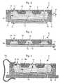
- FIG. 2shows in more detail the structure of the liquid droplet spray device 5 according to the present invention.
- Liquid substance 4enters spray device 5 by way of e.g. a very low pressure or capillary action.
- Such very low input pressureis important to provide very low exit velocity of the aerosol which is consequently easily absorbed into the inhalation air stream, limiting medication deposition losses in the extrathoracic region.
- Thiscan be achieved for example by way of at least one supply tube or needle 7 through which a liquid substance may be supplied from at least one reservoir 3 into spray device 5.
- this fillingmay also be piston or plunger activated, however with pressure reduction or performed by way of a pump or a micropump at very low pressure. This may be carried out as described in the document EP-A-0 641 934 .
- a micro-valve 17may be provided to isolate reservoir 3 from spray device 5.
- This valve 17may be external to the spray device as is shown, but it can also be integrated into the substrate or be part of the micropump supplying the filling.
- valve 17is controlled by medication flow measurement means 19 which are provided and which may be incorporated in spray device 5 thus allowing precise dosage in conjunction with the valve.
- the reservoir 3can be realised in a variety of forms so as to contain from several microliters to several millilitres.
- a non-volatile memory 29may further be suitably arranged within this reservoir 3.
- reservoir 3need not be provided at all or that liquid spray device 5 itself can act as a reservoir. This can be the case for example when substances cannot stay in a container over an extended period of time or are to be mixed before atomisation of the mixed component, one substance being contained in reservoir 3 and the other in the pre-filled spray device 5.
- non-volatile memory 29may contain information about a further provided vibrating means 10, which is explained in detail hereafter, and about identity and dosage of substance 4 or substances contained in reservoir 3 and in pre-filled liquid spray device 5.
- each liquid spray device 5is pre-filled with the desired unit dose of a substance 4.
- tube 7is plugged to seal space 9, or even non-existant and no valve is needed.
- space 9is dimensioned such that it may contain the required amount corresponding to the desired unit dose, and a number of pre-filled spray devices 5 form magazine 28 such as described earlier.
- Spray device 5consists thus of a housing formed of a superposition of a top substrate 18 and a bottom substrate 8 into which a space 9 is etched for containing liquid substance 4.
- bottom substrate 8thus has a thinner middle section acting as a membrane as will be explained furtheron.
- Bottom substrate 8may be made of glass, ceramics, silicon, high density polymer or the like.
- Top substrate 18may consist of plastic, high density polymer, ceramics, metal or silicon or the like for its main body, and of silicon for its nozzle body as will be explained in more detail further on.
- the substrates 8 and 18are attached to each other, for example by anodic or fusion bonding, so as to form and enclose space 9.
- Bottom substrate 8may also be fitted upside down with respect to the manner shown in figure 2 , so that the bottom of space 9 is flat, this allowing for a higher compression of the volume of space 9 and for a more compact spray device 5.
- Device 5also comprises a piezo-resistive element acting as the aforementioned flow measurement means 19.
- This means 19may be deposited on the inner surface of top substrate 18 or it may even be integrated into this top substrate and is located such that it may detect the flow of the droplets. For this reason, it is important that channels 15 and nozzles 14 are tightly sized and toleranced and have a defined, repeatable pressure drop.
- a selective hydrophilic coatingsuch as an amorphous material such as SiO2 may further be applied to provide a protective layer around the inside walls of space 9 and/or of cavities 13 which are located in top substrate 18 as is explained hereafter to avoid any contamination of substance 4 by the material of these walls and to improve wettability in certain parts. This may be carried out as described in the document EP-A-0 641 934 .
- This hydrophilic coatingwhich may be applied as a selective, patterned coating is advantageously coupled with a selective, patterned hydrophobic coating in certain areas of space 9, cavities 13 and on the outside of substrate 18.
- a hard amorphous carbon filme.g. a diamond-like carbon
- Such selective film coatingalso allows for a more complete emptying of space 9 due to reduced stiction.
- Such coating and its hydrophobic propertiescan be enhanced by fluorine plasma.
- the present Applicanthas found that such surface property specific coating influences and improves droplet size dispersion and provides an even better mono-dispersive pattern released by the spray device.
- substrate 18is made, at least partially, of a polymer, then a polymer with very low surface energy is used advantageously in combination with the selectively patterned hydrophobic coating.
- substrate 18is made of a polymer, acrylic or e.g. a photosensitive epoxy including or not said selective hydrophobic coating, e.g. a diamond-like nano-composite or Teflon® coating, a silicon etched mask, using the deep silicon etching process described hereafter, is preferably used by providing the masks on the wafer used to obtain the top substrate to facilitate precise plasma etching, e.g. 02 plasma or UV exposure of photosensitive materials, of the channels and of the output nozzles which are provided in the top substrate in said materials, as will be explained in more detail furtheron.
- plasma etchinge.g. 02 plasma or UV exposure of photosensitive materials, of the channels and of the output nozzles which are provided in the top substrate in said materials, as will be explained in more detail furtheron.
- Device 5preferably comprises a vibrating element 10, e.g. a piezoelectric element, attached to the exterior bottom surface of bottom substrate 8 in the vicinity of its thinner middle section to cause vibration of substance 4 in space 9 through the membrane part of substrate 8.
- this elementmay also be located separated from spray device 5 directly onto a PCB. This element may be glued to or deposited on the bottom surface of the spray device or on the PCB.
- Electrodes 11 and 12are applied to piezoelectric element 10 and to bottom substrate 8 respectively. These electrodes may be spring-contacts which contact appropriate electrodes (not shown) connected to electronic means 21 when the spray device 5 is rotated into its delivery position.
- clamping meansmay be provided to bring the spray device into contact with the piezoelectric element 10 as will be explained in more detail furtheron with reference to figure 4 .
- this piezoelectric elementmay be assembled to the thinner middle section of the bottom substrate which itself is assembled in the upside down manner mentioned above, a very compact spray device may be obtained.
- the operating data relating to vibrating element 10are contained in electronic circuitry 21 and non-volatile memory 29 contains only data relating to the identity and the dosage of the substance or substances to be delivered.
- the droplets sizeis inversely proportional to the excitation frequency as of a particular primary frequency and pressure.
- piezoelectric element 10vibrates at that particular primary frequency which may be for example around 470 kHz. Of course other frequencies may be used if appropriate. Indeed, several embodiments have been satisfactorly tested by the Applicant at a frequency of 100 kHz and even of 30 kHz. It should be noted that the lower the frequency, the lower the power consumption, but the higher the number of outlet nozzles so as to obtain a desired liquid substance output. This vibration may be generated in a known manner e.g. by using a frequency oscillator.
- a flexible heating surfacesuch as a captan film with heating element, not shown, can be suitably fitted on substrates 8 and 18, to heat the liquid substance, to e.g. around 37°C, by applying an electric current in an appropriate manner to this heating element.
- a conductive materialon the inner surface of bottom substrate 8, which thus corresponds to the bottom of space 9, to heat the liquid by applying a current to this conductive material.
- heatingmay contribute at the end of the atomisation cycle to evaporate any minute amount of liquid left in space 9, same as a continuation for a predetermined time of the actuating of the vibrating means after the inhalation cycle has ended.
- a temperature influence compensation of the frequency oscillatoris also provided to ensure that the excitation frequency of piezoelectric element 10 may be controlled by an appropriate feedback control circuit, again to avoid differences in droplet size and to ensure correct operation under varying ambient conditions.
- these feedback control means or compensation meansmay comprise at least one polynomial processor in which non-linearity compensation factors, such as those due to the temperature, the humidity or other environmental factors are pre-stored in the non-volatile memory device 29 such as e.g. an EEPROM, together with the corresponding medical device quality-controlled related data and medication identification and dosage instructions, as explained in more detail with figure 5 .
- Such an EEPROM or other memory deviceis preferably associated, in a modular fashion, with the reservoir, the valve etc., and the spray device, which might be disposable, according to the configuration, allowing to use the same power source 22 and electronic circuitry 21 for multiple diverse therapies.
- an asthmatic or a diabetic personmay use the same inhaler for two types of medication by exchanging the reservoir, the valve etc. and spray device module.
- the height of space 9is less than 400 ⁇ m
- the top surface of bottom substrate 8is etched away for about 200 ⁇ m for a spray device having a total top surface of about several square millimetres.
- top substrate 18may be formed of two materials, plastic for the main body, and silicon for the nozzle body.
- This nozzle bodycorresponds to a centre part of top substrate 18 which comprises outlet nozzles 14 and accesses from space 9 to these outlet nozzles.
- Siliconis preferably used for this nozzle body as it may be micromachined to obtain a very high precision manufacturing, such a high precision and absence of leachable components being much more difficult to obtain with plastics or the like, for instance by using an UV exposure or a plasma etching treatment of various plastic material, but silicon is also more expensive than plastics.
- top substrate 18may of course be made of only silicon or even of only plastics.
- Outlet nozzles 14 and accessesare formed in the nozzle body of the top substrate 18, so that the excited substance 4 may leave device 5 as a droplet spray.
- this top substrate 18is micromachined, for example in a well known anisotropic etching manner at several places to obtain tapered, pyramid-shaped cavities 13 which are for example about 200 to 400 ⁇ m deep. These pyramid shaped cavities can have a square or an elongated base and be of any number to provide the correct internal volume and flow characteristics for a particular substance 4.
- Each cavity 13then has a top surface having a side length of about 100 - 200 ⁇ m. Within this top surface of each cavity 13 at least one output channel 15 is provided to connect cavity 13 to an outlet nozzle at the exterior of top substrate 18.
- This output channelis preferably micromachined using a rapid deep vertical anisotropic plasma etching of silicon, e.g. at room temperature or low temperature and advanced silicon etch solution process.
- the Applicanthas developed techniques to machine these channels with a near vertical and smooth profile, thereby significantly reducing undercutting and maintaining tight control over tolerances. This provides for a precisely defined pressure drop, droplet size and flow behaviour across channel 15 for aqueous solutions and suspensions whereas the smooth surface is suited for medications carrying small solid particles, e.g. 1 to 3 ⁇ m, in suspensions. The same effect can be obtained proportionally with larger dimensions, e.g. with nozzles of 10 ⁇ m or larger.
- each output channel 15At the outer end of each output channel 15 at least one output nozzle 14 is provided through which the excited liquid substance is ejected as a droplet spray.
- the used technologyallows to etch extremely precise, deep channels having straight and smooth side-walls and being round or square with a very tight, repeatable tolerance and allows to etch areas around nozzles 14 as explained herebelow.
- the process between lithography and etchingcan be arranged so as to adapt the lithography mask to the desired diameter as a function of the process tolerances thus guaranteeing the uniform precision of the nozzles and of the droplets.
- each output channel 15is about 15 ⁇ m long and 5 ⁇ m wide with nozzle 14 having a maximum opening of around 5 ⁇ m.
- a selective, patterned hard amorphous carbon filme.g. diamond-like carbon, of for example 100 nm (10-9 m) is deposited in various areas, notably inside all or part of cavity 13 and output channel 15, certain areas of space 9 and on all or part of the outside of substrate 18.
- Such coatingfurther improves smoothness and lowers flow resistance in channel 15.
- FIG 3shows a second embodiment of liquid spray device 5 in which vibrating element 10 and bottom substrate 8 are advantageously replaced by a single piezoelectric ceramic element 10 of an appropriate shape.
- the different parts which correspond to those of figure 2have been indicated by the same reference numerals.
- a protective glass or a silicon-nitrate layer, referenced 8a,is deposited on this vibrating element 10 to isolate the latter from substance 4. This deposition avoids undesired leachables from the vibrating element 10 or its electrode into the drug substance.
- the selective, patterned hydrophilic or hydrophobic coatingcan be applied similar as to the previous embodiment.
- FIG. 4shows a third embodiment of liquid spray device 5 as described in the previous embodiments in which the vibrating element 10 does not form part of spray device 5 as such. Instead, this element 10 is arranged on a support, for example a PCB, indicated by reference P, which may further contain e.g. the electrodes, the power source and the electronic means 21 for the vibration generation and dosage control including a non-volatile memory for the functional parameters of the piezoelectric element 10. Liquid spray device 5 may then be brought into tight contact with piezoelectric element 10 using appropriate attachment means, e.g. by one or more clamping devices 10a, for attaching the spray device to the PCB. Together, this spray device and the PCB comprising the vibrating means, i.e.
- this spray device and the PCBcomprising the vibrating means, i.e.
- Clamping means 10amay be provided either as a separate element or may be formed integrated with the PCB to allow for a quick clamping of spray device 5. Such clamping means are well-known as such and may be readily conceived by a skilled person.
- the top substratemay be micromachined in such a way as to provide recessed areas around output nozzles 14 such as shown.
- Such top substrate 18amay of course also be used in the embodiments of figures 2 or 3 .
- Such recessed areas in combination with straight output channels 15 and tightly toleranced output nozzles 14contribute to the monodispersive nature of the ejected spray by providing minimum stiction surface for the liquid 4 around output nozzles 14.
- the ratios between the different individual dimensionssuch as the internal volume height of space 9, the distance between the nozzles, the length of the membrane part of substrate 8 etc. result in factors such as compression ratio, stroke amplitude of the membrane etc. which together with the electronic parameters such as amplitude and frequency allow to adapt the inventive spray device to various liquid characteristics such as viscosity.
- the diameter of a dropletdepends on the nozzle hole size for a given frequency of the vibration of the liquid substance and the inlet pressure. In the present example where a frequency of around 470 kHz is used, the droplet diameter has been found to be around 5 ⁇ m, the diameter of the hole of nozzle 14 is around 7 ⁇ m and the inlet pressure is a few millibar.
- One such a dropletthus contains a quantity of around 67 femtoliters (10-15 l) so that as such the number of nozzles may be determined as a function of the amount to be ejected. In a practical case, the number of nozzles may vary from around 600 to about 1500.
- a frequency vibration adaptationmay be provided. Indeed, the exact resonance frequency of the piezoelectric vibrating element varies from one piece to another and as a function of ambient conditions such as the temperature.
- the liquid droplet spray deviceis a disposable part of the inhaler containing the reservoir as described above, it is advantageous to further provide the aforementioned EEPROM memory device with parameters containing the exact resonance frequency of the vibrating piezoelectric element forming part of the liquid droplet spray device.
- Electronic means 21are preferably arranged to detect and to correct mode and frequency range of a particular piezoelectric element, to read this information and to adapt the vibration frequency to be applied to the piezoelectric element accordingly so that the new device will continue to function correctly under varying environmental conditions such as ambient temperature.
- Inhaler 1further comprises control means 16 (see figure 5 ) for controlling the amount of droplets to be ejected. This amount depends on the amount of drug which is to reach the different parts of the lungs.
- Control means 16which may form part of electronic circuitry 21, advantageously further comprise an inhalation flow sensor 7 located conveniently, in this example near mouthpiece 6.
- Such a flow sensoris know per se, see e.g. the aforementioned document WO 92/15353 . In this document, the sensor is used to determine an operating range within which the inhaler, a pMDI or a piston-activated device, will be activated.
- the inhalation flow sensor 7is used in conjunction with the medication flow measurement means 19 and/or a lung model, explained hereafter, implemented in electronic means 21 to effectively measure and control drug flow for every inhalation according to a lung model calculation which is explained below and in connection with temperature measurement to provide a flow and temperature controlled unit dose.
- medication flow measurement means 19are realised in the way of a differential pressure sensor allowing a more complete supervision of the spray device by not only measuring the flow, but which may also detect an empty reservoir 3 and or space 9 as well as a possible occlusion.
- the present Applicanthas used, and implemented in electronic circuitry, a model of the lungs and of their functioning and, through a great amount of experimentation the following has been observed.
- the lungs which have 23 generationsmay be separated in three different regions: the trachea (until the sixth generation), the centre region (until the 16th generation) and the alveoli.
- the tracheauntil the sixth generation
- the centre regionuntil the 16th generation
- the alveolialveoli.
- a certain droplet sizeis more suitable for effectively reaching the different regions.
- a droplet having a size of around 3 to 5 ⁇ mwill easier reach the alveoli region, but a droplet with a size of around 10 ⁇ m will reach the centre region, whereas a droplet size of around 16 ⁇ m assures that the droplets arrive at the trachea region.
- Vis a loss factor due to exhalation of the patient before the droplets have reached their target
- Xis a loss factor due to sedimentation, or gravity, of the drug
- Yis a loss factor due to impact loss at a bifurcation of lung branches
- Zis a loss factor due to diffusion in the lungs.
- a signal processing and digital compensation circuitry including a polynomial processorhas been realised by the present Applicant for control means 16, for storing and processing the non-linearities of the inhalation flow sensor 7, medication flow sensor 19 and piezoelectric element 10.
- Figure 5shows an example of a block diagram of the electronic circuit means 21 and its relation to the different elements such as the mentioned compensation means controlled by this means 21.
- the electronic means 21receives parameters containing information coming from the inhalation flow means 7 at input I1, from medication flow means 19 at input I2, from a temperature sensitive element (not shown) at input I3 and from EEPROM 29 incorporated in reservoir 3 at inpot I4.
- Electronic means 21contains at least one polynomial processor unit 21a arranged to receive and to sequentially process these parameters, an EEPROM or other non-volatile memory 21b connected to a first input/output of processor 21a, control means 16 in the form of a microcontroller connected to the output of EEPROM 21b and to another input/output of processor 21a, a vibrating element frequency oscillator driving stage 21d connected to the output of microcontroller 16 to adapt the frequency to be applied to vibrating element 10, and thus forming the aforementioned compensation means, and a booster valve control means 21c adapted to control the position of an optionally available boosting means as explained below.
- an output O1may be provided to adapt the position of a suitably arranged booster valve as explained in more detail furtheron.
- Two other outputs 02 and 03connect the output of the vibrating element frequency oscillator driving stage 21d to the electrodes 11, 12 respectively for exciting piezoelectric element 10.
- EP-A1-07 484 82allows for programming drug dosage as a function of the patient (his age, height etc.) and of various control parameters, such as inhalation flow rate, ambient temperature, deposition set point, etc..
- the mentioned circuitry for control means 16can of course be implemented as a very low power ASIC or using a microcontroller using the same or a similar software program.
- the piezoelectric element frequency oscillator driving stage 21dis realised in high voltage (10 to more than 30 volts) CMOS technology.
- Figure 6shows a graph indicating the amount of droplets deposited in a particular lung region of an adult at a given flow rate with time for a given monodispersive droplet size and ratio.
- the inhalation flow rateis 20 l/min
- the droplet sizeis 5 ⁇ m.
- the graphis shown for a specific vibration frequency and for a certain number of nozzles of the liquid spray device. In this example of the deposition representation, the number of nozzles is 50 whereas the vibration frequency is 100 kHz. It should be noted that this graph represents a theoretical situation based on the above-mentioned lung model so that the indicated deposition after the 23rd lung generation is of course to be ignored.
- the figureshows several graphs, each graph representing a given time elapsed after the start of the inhalation cycle. It may be seen from this graph that after a first given time, in this example after 300 ms which corresponds to graph A, a certain peak amount of droplets, around 250,000, have been deposited around the 18th and 20th lung generation. After 600 ms, graph B, more droplets have been deposited, around 600,000, but the peak deposition remains around the 18th to the 20th lung generation. After 1000 ms, graph C, around 1,200,000 droplets have been deposited, also in this peak deposition region, whereas after about 1.3 seconds, see graph D, almost 1,600,000 droplets are deposited there.
- the lung modelthus allows for a predicted deposition of droplets at certain lung regions depending on parameters which may be controlled by a skilled person
- the droplet sizemay be determined by the specific structure, and as the droplets are mono-dispersive, the total amount released may be determined.
- the amount of droplets to be ejectedmay be controlled by the control means 16 in accordance with equation 1 which may be pre-programmed into these control means 16.
- the amount of droplets to be ejectedmay be determined and the control means may thus interrupt the ejection when the amount ejected has reached the desired amount. This may be performed by including measurement means such as the medication flow measurement means 19 within the spray device so as to allow for a determination of the amount ejected.
- measurement meanssuch as the medication flow measurement means 19 within the spray device so as to allow for a determination of the amount ejected.
- Such meansare in principle well known in the field, see e.g. the already mentioned document WO 92/11050 .
- a piezoelectric resistoris deposited inside top substrate 18 or 18a at a suitable location near the exterior of spray device 5. It can be assumed that the pressure outside spray device 5 is close to ambient pressure.
- the innovation of this variantresides in combining the inhalation flow sensor mentioned above and this internal pressure sensor, which is the flow measurement means 19, to determine the differential pressure allowing to measure the drug flow.
- the piezoelectric resistormay form part of half a resistor bridge to measure the pressure, whereas the ambient pressure or the pressure inside mouthpiece 6 is considered known so that a differential pressure calculation may be determined.
- this flow measurement means 19may be integrated within top substrate 18 or 18a.
- boosting meansare further preferably provided which are placed between the outlet nozzles 14 and mouthpiece 6.
- Such boosting meansmay comprise a duct having a pressure-drop section through which the droplet spray passes.
- Pressure control meanse.g. in the form of a valve-opening, are then provided in the duct to allow to lower the resistance in the duct.
- an accurate prediction of place of deposition and of quantity of the drug substancemay be carried out, thus resulting in a deposition optimisation so that a more efficient therapy may be obtained than is the case for the mentioned prior art device.
- the mentioned inhalation sensormay also be used, with suitable adaptation, as an exhalation flow sensor in order to train patients to retain their breath for a certain period of time to aid the retention of medication, or to minimise the above mentioned exhalation losses, but also to correlate the mentioned exhalation loss factor V.
- the inventive spray devicemay be used in a highly reliable inhaler for critical medications which comprises to this effect at least two spray devices.
- the flow measurement means 19allow to detect plugging or blocking of nozzles and/or an empty reservoir as is mentioned here above, it is thus also possible to detect the operation of the spray device itself, i.e. if this spray device is still functioning.
- the inhalermay thus, if a spray device is considered to be inoperative, switch, via electronic means 21, to another spray device to maintain the intended drug flow.
- Appropriate adaption to the electronic and/or control meansmay be provided to this effect, as such means may be conceived readily by a skilled person, they will not be described in detail here. Thanks to this redundancy of spray devices, a continuous reliable operation of the inhaler is obtained.
Landscapes
- Health & Medical Sciences (AREA)
- Engineering & Computer Science (AREA)
- Animal Behavior & Ethology (AREA)
- Anesthesiology (AREA)
- Biomedical Technology (AREA)
- Heart & Thoracic Surgery (AREA)
- Hematology (AREA)
- Life Sciences & Earth Sciences (AREA)
- General Health & Medical Sciences (AREA)
- Public Health (AREA)
- Veterinary Medicine (AREA)
- Pulmonology (AREA)
- Bioinformatics & Cheminformatics (AREA)
- Special Spraying Apparatus (AREA)
- Medicinal Preparation (AREA)
Description
- The present invention relates generally to drug administration devices, and in particular to a device for administrating a drug to a patient by means of his or her respiratory system. Such an inhalation device, in its simplest form, is commonly called an inhaler. It may be used e.g. for the controlled administration of drugs or for a variety of therapies using aerosolised drug administration including anaesthetics. The inhaler delivers the drug, which is in the form of a liquid substance, as a dispersion of atomised droplets. Preferably; such a device is small in size and battery operated so that the patient may carry and use it in a discreet manner. Preferably also the device is made in such a way that it is possible to use the same device for administrating more than one drug and to distinguish one drug from another. More specifically, the present invention concerns the liquid droplet spray device which creates the droplet spray of the inhaler or aerosolised drug delivery system and its control means.
- Various devices are known for atomising a liquid.
Document EP 0 516 565 describes am ultrasonic wave nebuliser which atomises water. This apparatus is used as a room humidifier. Vibration is transmitted through the water to the water surface from which the spray is produced. A perforate membrane is provided to retain the water in absence of oscillation. Such devices are particularly ineffective in vaporising suspensions as explained in the Research Article« Comparison of a respiratory suspension aerosolised by an air-jet and an ultrasonic nebuliser » by Susan L. Tiano and Richard N. Dalby in Pharmaceutical Development and Technology, I(3), 261-268 (1996). Typically, inhaler devices do use the same principle to atomise the liquid into droplets, see for example the documentWO 95/15822 - However, the droplet size does not only depend on the size of the outlet orifices of the perforate membrane, but is also dependant on the vibration frequency. In order to obtain a small droplet, a very high frequency must be used, typically over 1 MHz for droplets of about 10 µm in diameter. This leads to an increased power consumption due to the high frequency so that such a device is not suitable for a small battery operated device. Furthermore, the exact size of the droplet is not always constant due to frequency response fluctuations with temperature and to membrane fabrication tolerances.
- As is generally known, the efficacy of a drug therapy treatment depends on the substance's activity, which depends on the composition, on the place of impact, i.e. the place at which it may carry out its activity, and on the dose repeatability, i.e. the fact that the volume of each dose ejected remains constant.
- With a large variation of droplet size, it is almost impossible to determine the quantity and where exactly the droplets will arrive. In fact, the liquid atomised by the inhaler is to reach certain parts of the lungs to have a maximum effect dependant on the therapy. It is thus desirable to be able to determine or to "target" the impact or deposition position of the droplets to obtain an efficient therapy.
- Further, the orifices can not be made too small, not only because of fabrication reasons, but also in order to avoid clogging of the outlet orifices by the substance. In fact, it is known that the aqueous solubility of the substance solution depends on the composition of the drugs used and on its temperature. It is also known that such orifices might be clogged by very small amounts of drug left in the liquid spray device after atomisation.
- To ensure that a certain amount of substance is indeed released, it has been proposed to monitor the amount of liquid released when the inhaler is used. The document
WO 92/11050 - Another prior art device is known from the document
US-A-5,497,763 . This device has a breath actuated release of aerosolised drug and has a porous membrane located above a dosage unit container. The pores are preferably cone-shaped to reduce the force needed to move the drug substance therethrough when collapsing the container. However, such a membrane is difficult to manufacture as the reproducibility of the pores is poor. Also, the difference in length and diameter of the pore channel results in a considerable difference of pressure drop across this channel. This varying pressure drop will thus also lead to a variation of the quantity and droplet size dispersion of the drug being expelled. Another problem is the alignment of the movable membrane with pores over each unit container resulting in another source of uncertainty over the expelled amount of drug. - Indeed, the fabrication tolerance Δd of the pores, or outlet nozzles, is an essential factor in controlling and determining the amount, i.e. the volume of an expelled droplet. In fact, this volume V depends on d3 (V= 1/6 * ¶d3), d being the diameter of the outlet nozzle. For example, if d = 5 µm, and Δd = ±0.5 µm, the droplet volume V may vary from 47.5 (d= 4.5) to 87 (d=5.5) which is a variation of 83%, far too high for usual industry standards. The United States FDA (Food and Drug Administration) imposes a repeatability of ±20% for 90% of the droplets, and ±25% for the remaining 10%. Both the device according to
WO 92/11050 US-A-5,497,763 do not allow for such precision and repeatability. - Also, the pre-cited documents are silent about avoiding layers or areas of liquid drug forming on the outside surface of the nozzle array by well known capillary action and stiction. This is especially the case with devices where the same nozzle array is used several times, such as for example in the documents
WO 92/11050 WO 90/01997 - The document
US-A-5,497,763 partially overcomes this problem by separating dosage containers and the porous membrane though which the drug is aerosolised. However, the solution does not allow for the precision and repeatability of the cone-shaped pores used and the precise control of the drug delivery, requiring a pressure to be applied additionally to the piezoelectric vibrating means to force the liquid out. Also, the piezoelectric vibrating means is not compensated for its non-linearities adding to uncontrolled factors affecting the delivery of targeted delivery. - It is, therefore, an object of the present invention to provide a liquid droplet spray device for an inhaler, as well as an inhaler itself, suitable for respiratory therapies which overcomes, at least partially, the inconveniences of the prior art and which allows for a true targeting of the impact of droplets thereby assuring a constant droplet size. In fact, this virtually constant physical size of the droplets, or mono-dispersion of the droplets allows for an exact determination of the volume of liquid released and deposited.
- It is another object of the present invention to provide such a device which is simple, reliable to manufacture, small in size and low in cost.
- Thus, the present invention concerns a liquid droplet spray device according to
present claim 1. The present invention further concerns an inhaler according toclaim 16 allowing for a predicted deposition, comprising several inventive spray devices to obtain a highly reliable operating system for anaesthetics or critical medication nebulisation thanks to an operating redundancy of the spray devices. - Thanks to the specific structure of the dispersion or outlet nozzle of the spray device according to the present invention, i.e. thanks to the combination of a tapered cavity with a number of identically sized and toleranced straight non-tapered channels or distribution of such channels with different dimensions, it is possible to obtain a high precision, tightly toleranced output nozzle array resulting in a virtually mono-dispersive droplet size so that it is possible to determine with improved accuracy, compared to prior art devices, the place of impact, i.e. the deposition of the droplets on the different selected lung sections as well as the amount of substance that arrives there. Further, thanks to flow measurement and pressure supervision means which are preferably incorporated into the inventive spray generating device, it is also possible to conclude with precision on the delivered dose, and thanks to control means which are further preferably provided, it is possible to calculate a predicted deposition of the mono-dispersive droplets and to adapt to the type of medication and patient concerned. Thus, an efficient therapy may be performed. Further, thanks to the inventive spray device, only a minimal amount of liquid is used as the exact amount released can be predetermined with a high precision so that there is only a very small amount of waste and that the side-effects can be limited too.
- Other features and advantages of the liquid spray device according to the present invention will become clear from reading the following description which is given solely by way of a non-limitative example thereby referring to the attached drawings in which :
Figure 1 shows a preferred embodiment of an inhaler suitable for respiratory therapies comprising a liquid droplet spray device according to the present invention,Figure 2 is a schematic cross-section of a first embodiment of the liquid droplet spray device according to the present invention,Figure 3 is a schematic cross-section of a second embodiment of the liquid droplet spray device according to the present invention,Figure 4 is a schematic cross-section of a third embodiment of the liquid droplet spray device according to the present invention,Figure 5 shows a schematic block diagram of the electronic circuitry used in the inhaler according to the present invention, andFigure 6 is a graphic representation of the deposition of the number of droplets against the lung generation for a given flow rate and as a function of time.- Referring now to
Figure 1 , an embodiment of an inhaler suitable for respiratory therapies is indicated bygeneral reference 1.Inhaler 1 comprises ahousing 2 having amagazine 28 which may comprise areservoir 3 containing aliquid drug substance 4.Housing 2 is connected to amouthpiece 6 in communication with the exterior ofhousing 2 to allow delivery of the drug to the patient by way of his mouth. Naturally,mouthpiece 6 may be replaced by a nasal piece, or may be fitted with a nasal adapter to allow the inhaler to deliver the drug through the nose of the patient instead of through his mouth. However, reference will be made throughout the present description to a mouthpiece only thereby meaning a mouthpiece or a nasal piece or a nasal adapter or a nebulising set with or without a face mask. - For ease of use,
housing 2 may consist of two separable parts,upper part 2a andlower part 2b respectively, interconnected byhinges document EP 0 824 023 .Lower housing part 2b has mounted thereinmagazine 28 which comprises at least one drug delivery system in the form of at least one liquiddroplet spray device 5 each containing a space 9 (seefigure 2 ) for storingliquid substance 4.Magazine 28 may further comprise a non volatile memory means 29 connected to electronic circuitry or means 21, and aportable power source 22, such as a lithium battery.Upper housing 2a may contain additional magazines as a reserve.Magazine 28 is rotatably mounted inlower housing part 2b about anaxis 23 so that, upon rotation ofmagazine 28 about thisaxis 23, eachspray device 5 is placed, in turn, in a delivery position with respect tomouthpiece 6. To this effect, the magazine may be caused to rotate aboutaxis 23 by a stepper motor, not shown, controlled byelectronic circuitry 21. Each spray device may comprise a sealant to maintainsubstance 4 withinspace 9 and which is peeled off when the spray device is aligned withmouthpiece 6. Such sealants are well known in the art and will not be explained in more detail here. However, it is also possible that there is only onespray device 5 which is re-filled whenever necessary fromreservoir 3 by way of a micro-valve 17 controlling this filling. - Thus,
reservoir 3 is connected toliquid spray device 5 which comprisesspace 9 containing a unit dose, such as 10 to 30 µl or another suitable small amount ofdrug substance 4.Liquid spray device 5 creates droplets ofsubstance 4 by atomising the liquid substance as will be explained in more detail further on. The droplets are released intomouthpiece 6, or the nasal adapter or the nebulising set, which has an open end to be inserted into the mouth, or nose, of a person so that the droplets may enter his or her respiratory airway. Figure 2 shows in more detail the structure of the liquiddroplet spray device 5 according to the present invention.Liquid substance 4 entersspray device 5 by way of e.g. a very low pressure or capillary action. Such very low input pressure is important to provide very low exit velocity of the aerosol which is consequently easily absorbed into the inhalation air stream, limiting medication deposition losses in the extrathoracic region. This can be achieved for example by way of at least one supply tube orneedle 7 through which a liquid substance may be supplied from at least onereservoir 3 intospray device 5. However, this filling may also be piston or plunger activated, however with pressure reduction or performed by way of a pump or a micropump at very low pressure. This may be carried out as described in the documentEP-A-0 641 934 . As mentioned, a micro-valve 17 may be provided to isolatereservoir 3 fromspray device 5. Thisvalve 17 may be external to the spray device as is shown, but it can also be integrated into the substrate or be part of the micropump supplying the filling. Preferably,valve 17 is controlled by medication flow measurement means 19 which are provided and which may be incorporated inspray device 5 thus allowing precise dosage in conjunction with the valve. Thereservoir 3 can be realised in a variety of forms so as to contain from several microliters to several millilitres. Anon-volatile memory 29 may further be suitably arranged within thisreservoir 3.- However, it should be noted that
reservoir 3 need not be provided at all or thatliquid spray device 5 itself can act as a reservoir. This can be the case for example when substances cannot stay in a container over an extended period of time or are to be mixed before atomisation of the mixed component, one substance being contained inreservoir 3 and the other in thepre-filled spray device 5. In any case,non-volatile memory 29 may contain information about a further provided vibratingmeans 10, which is explained in detail hereafter, and about identity and dosage ofsubstance 4 or substances contained inreservoir 3 and in pre-filledliquid spray device 5. In another case, eachliquid spray device 5 is pre-filled with the desired unit dose of asubstance 4. Of course, when there is noseparate reservoir 3,tube 7 is plugged to sealspace 9, or even non-existant and no valve is needed. Thusspace 9 is dimensioned such that it may contain the required amount corresponding to the desired unit dose, and a number ofpre-filled spray devices 5form magazine 28 such as described earlier. Spray device 5 consists thus of a housing formed of a superposition of atop substrate 18 and abottom substrate 8 into which aspace 9 is etched for containingliquid substance 4. In the embodiment as shown infigure 2 ,bottom substrate 8 thus has a thinner middle section acting as a membrane as will be explained furtheron.Bottom substrate 8 may be made of glass, ceramics, silicon, high density polymer or the like.Top substrate 18 may consist of plastic, high density polymer, ceramics, metal or silicon or the like for its main body, and of silicon for its nozzle body as will be explained in more detail further on. Thesubstrates space 9.Bottom substrate 8 may also be fitted upside down with respect to the manner shown infigure 2 , so that the bottom ofspace 9 is flat, this allowing for a higher compression of the volume ofspace 9 and for a morecompact spray device 5.Device 5 also comprises a piezo-resistive element acting as the aforementioned flow measurement means 19. This means 19 may be deposited on the inner surface oftop substrate 18 or it may even be integrated into this top substrate and is located such that it may detect the flow of the droplets. For this reason, it is important thatchannels 15 andnozzles 14 are tightly sized and toleranced and have a defined, repeatable pressure drop.- A selective hydrophilic coating, such as an amorphous material such as SiO2, may further be applied to provide a protective layer around the inside walls of
space 9 and/or ofcavities 13 which are located intop substrate 18 as is explained hereafter to avoid any contamination ofsubstance 4 by the material of these walls and to improve wettability in certain parts. This may be carried out as described in the documentEP-A-0 641 934 . This hydrophilic coating which may be applied as a selective, patterned coating is advantageously coupled with a selective, patterned hydrophobic coating in certain areas ofspace 9,cavities 13 and on the outside ofsubstrate 18. In order to maintain the protective aspect of these surfaces and at the same time to reduce the internal and external stiction due to capillary forces inspace 9, and especially on the outside ofsubstrate 18, a hard amorphous carbon film, e.g. a diamond-like carbon, is provided, preferably in a selective patterned manner in these areas. Such selective film coating also allows for a more complete emptying ofspace 9 due to reduced stiction. Such coating and its hydrophobic properties can be enhanced by fluorine plasma. - The present Applicant has found that such surface property specific coating influences and improves droplet size dispersion and provides an even better mono-dispersive pattern released by the spray device.
- If
substrate 18 is made, at least partially, of a polymer, then a polymer with very low surface energy is used advantageously in combination with the selectively patterned hydrophobic coating. Ifsubstrate 18 is made of a polymer, acrylic or e.g. a photosensitive epoxy including or not said selective hydrophobic coating, e.g. a diamond-like nano-composite or Teflon® coating, a silicon etched mask, using the deep silicon etching process described hereafter, is preferably used by providing the masks on the wafer used to obtain the top substrate to facilitate precise plasma etching, e.g. 02 plasma or UV exposure of photosensitive materials, of the channels and of the output nozzles which are provided in the top substrate in said materials, as will be explained in more detail furtheron. Device 5 preferably comprises a vibratingelement 10, e.g. a piezoelectric element, attached to the exterior bottom surface ofbottom substrate 8 in the vicinity of its thinner middle section to cause vibration ofsubstance 4 inspace 9 through the membrane part ofsubstrate 8. However, this element may also be located separated fromspray device 5 directly onto a PCB. This element may be glued to or deposited on the bottom surface of the spray device or on the PCB.Electrodes piezoelectric element 10 and tobottom substrate 8 respectively. These electrodes may be spring-contacts which contact appropriate electrodes (not shown) connected toelectronic means 21 when thespray device 5 is rotated into its delivery position. If the element is arranged on the PCB with or without intermediary elements, clamping means may be provided to bring the spray device into contact with thepiezoelectric element 10 as will be explained in more detail furtheron with reference tofigure 4 . As may be readily understood, by assembling this piezoelectric element to the thinner middle section of the bottom substrate which itself is assembled in the upside down manner mentioned above, a very compact spray device may be obtained. In this case for example, the operating data relating to vibratingelement 10 are contained inelectronic circuitry 21 andnon-volatile memory 29 contains only data relating to the identity and the dosage of the substance or substances to be delivered.- It has been observed that the droplets size is inversely proportional to the excitation frequency as of a particular primary frequency and pressure. Preferably,
piezoelectric element 10 vibrates at that particular primary frequency which may be for example around 470 kHz. Of course other frequencies may be used if appropriate. Indeed, several embodiments have been satisfactorly tested by the Applicant at a frequency of 100 kHz and even of 30 kHz. It should be noted that the lower the frequency, the lower the power consumption, but the higher the number of outlet nozzles so as to obtain a desired liquid substance output. This vibration may be generated in a known manner e.g. by using a frequency oscillator. - Advantageously, a flexible heating surface, such as a captan film with heating element, not shown, can be suitably fitted on
substrates bottom substrate 8, which thus corresponds to the bottom ofspace 9, to heat the liquid by applying a current to this conductive material. - Thanks to this heating, the influence of any temperature fluctuations on
substance 4, and in particular on the particles which this substance contains, may be largely controlled. In fact, it is known that the dimensions of steroids which are commonly used in a drug substance vary with the temperature and become more soluble with a higher temperature, see for more details the article "Steroid / Cyclodextrin complexes for pulmonary delivery " by G.M. Worth, M. Thomas, S.J. Farr and G. Taylor; Proceed. Int'l Symp. Control. Rel. Bioact. Mater., 24 (1997), pages 747 & 748, Controlled Release Society Inc. Furthermore, thanks to this heating, humidity influences due to the environment in which the spray device operates may also be taken into account to ensure correct functioning. - Furthermore, such heating may contribute at the end of the atomisation cycle to evaporate any minute amount of liquid left in
space 9, same as a continuation for a predetermined time of the actuating of the vibrating means after the inhalation cycle has ended. - Preferably, a temperature influence compensation of the frequency oscillator is also provided to ensure that the excitation frequency of
piezoelectric element 10 may be controlled by an appropriate feedback control circuit, again to avoid differences in droplet size and to ensure correct operation under varying ambient conditions. In a preferred embodiment, these feedback control means or compensation means may comprise at least one polynomial processor in which non-linearity compensation factors, such as those due to the temperature, the humidity or other environmental factors are pre-stored in thenon-volatile memory device 29 such as e.g. an EEPROM, together with the corresponding medical device quality-controlled related data and medication identification and dosage instructions, as explained in more detail withfigure 5 . - Such an EEPROM or other memory device is preferably associated, in a modular fashion, with the reservoir, the valve etc., and the spray device, which might be disposable, according to the configuration, allowing to use the
same power source 22 andelectronic circuitry 21 for multiple diverse therapies. For example, an asthmatic or a diabetic person may use the same inhaler for two types of medication by exchanging the reservoir, the valve etc. and spray device module. - An example of the dimensions of the different parts of
spray device 5 is given hereafter The height ofspace 9 is less than 400 µm, the top surface ofbottom substrate 8 is etched away for about 200 µm for a spray device having a total top surface of about several square millimetres. - As mentioned above, in a preferred embodiment,
top substrate 18 may be formed of two materials, plastic for the main body, and silicon for the nozzle body. This nozzle body corresponds to a centre part oftop substrate 18 which comprisesoutlet nozzles 14 and accesses fromspace 9 to these outlet nozzles. Silicon is preferably used for this nozzle body as it may be micromachined to obtain a very high precision manufacturing, such a high precision and absence of leachable components being much more difficult to obtain with plastics or the like, for instance by using an UV exposure or a plasma etching treatment of various plastic material, but silicon is also more expensive than plastics. However,top substrate 18 may of course be made of only silicon or even of only plastics.Outlet nozzles 14 and accesses are formed in the nozzle body of thetop substrate 18, so that theexcited substance 4 may leavedevice 5 as a droplet spray. To this effect, thistop substrate 18 is micromachined, for example in a well known anisotropic etching manner at several places to obtain tapered, pyramid-shapedcavities 13 which are for example about 200 to 400 µm deep. These pyramid shaped cavities can have a square or an elongated base and be of any number to provide the correct internal volume and flow characteristics for aparticular substance 4. Eachcavity 13 then has a top surface having a side length of about 100 - 200 µm. Within this top surface of eachcavity 13 at least oneoutput channel 15 is provided to connectcavity 13 to an outlet nozzle at the exterior oftop substrate 18. This output channel is preferably micromachined using a rapid deep vertical anisotropic plasma etching of silicon, e.g. at room temperature or low temperature and advanced silicon etch solution process. The Applicant has developed techniques to machine these channels with a near vertical and smooth profile, thereby significantly reducing undercutting and maintaining tight control over tolerances. This provides for a precisely defined pressure drop, droplet size and flow behaviour acrosschannel 15 for aqueous solutions and suspensions whereas the smooth surface is suited for medications carrying small solid particles, e.g. 1 to 3 µm, in suspensions. The same effect can be obtained proportionally with larger dimensions, e.g. with nozzles of 10 µm or larger. - Thus, at the outer end of each
output channel 15 at least oneoutput nozzle 14 is provided through which the excited liquid substance is ejected as a droplet spray. The used technology allows to etch extremely precise, deep channels having straight and smooth side-walls and being round or square with a very tight, repeatable tolerance and allows to etch areas aroundnozzles 14 as explained herebelow. The process between lithography and etching can be arranged so as to adapt the lithography mask to the desired diameter as a function of the process tolerances thus guaranteeing the uniform precision of the nozzles and of the droplets. In the present example, eachoutput channel 15 is about 15 µm long and 5 µm wide withnozzle 14 having a maximum opening of around 5 µm. Dimensions as well as the number of nozzles may of course be readily modified depending on the amount of drug and on the corresponding droplet size to be ejected as will be explained in more detail here after. However, it should be noted that the length of thisoutput channel 15 should not be too long to avoid a large pressure drop across this channel resulting in a change of the droplet size as ejected. - Preferably, a selective, patterned hard amorphous carbon film, e.g. diamond-like carbon, of for example 100 nm (10-9 m) is deposited in various areas, notably inside all or part of
cavity 13 andoutput channel 15, certain areas ofspace 9 and on all or part of the outside ofsubstrate 18. Such coating further improves smoothness and lowers flow resistance inchannel 15. Figure 3 shows a second embodiment ofliquid spray device 5 in which vibratingelement 10 andbottom substrate 8 are advantageously replaced by a single piezoelectricceramic element 10 of an appropriate shape. The different parts which correspond to those offigure 2 have been indicated by the same reference numerals. A protective glass or a silicon-nitrate layer, referenced 8a, is deposited on this vibratingelement 10 to isolate the latter fromsubstance 4. This deposition avoids undesired leachables from the vibratingelement 10 or its electrode into the drug substance. The selective, patterned hydrophilic or hydrophobic coating can be applied similar as to the previous embodiment.Figure 4 shows a third embodiment ofliquid spray device 5 as described in the previous embodiments in which the vibratingelement 10 does not form part ofspray device 5 as such. Instead, thiselement 10 is arranged on a support, for example a PCB, indicated by reference P, which may further contain e.g. the electrodes, the power source and the electronic means 21 for the vibration generation and dosage control including a non-volatile memory for the functional parameters of thepiezoelectric element 10.Liquid spray device 5 may then be brought into tight contact withpiezoelectric element 10 using appropriate attachment means, e.g. by one ormore clamping devices 10a, for attaching the spray device to the PCB. Together, this spray device and the PCB comprising the vibrating means, i.e. the piezoelectric element, form a liquid spray device assembly which functionally corresponds to the spray device offigures 2 and 3 . Clamping means 10a may be provided either as a separate element or may be formed integrated with the PCB to allow for a quick clamping ofspray device 5. Such clamping means are well-known as such and may be readily conceived by a skilled person. Furthermore, the top substrate may be micromachined in such a way as to provide recessed areas aroundoutput nozzles 14 such as shown. Suchtop substrate 18a may of course also be used in the embodiments offigures 2 or 3 . Such recessed areas in combination withstraight output channels 15 and tightlytoleranced output nozzles 14 contribute to the monodispersive nature of the ejected spray by providing minimum stiction surface for theliquid 4 aroundoutput nozzles 14.- The ratios between the different individual dimensions, such as the internal volume height of
space 9, the distance between the nozzles, the length of the membrane part ofsubstrate 8 etc. result in factors such as compression ratio, stroke amplitude of the membrane etc. which together with the electronic parameters such as amplitude and frequency allow to adapt the inventive spray device to various liquid characteristics such as viscosity. - Thanks to the inventive arrangement of
spray device 5, virtually mono-dispersive droplets are ejected which allow for a precise calculation of the amount of drug which will enter the various parts of the lungs. As the top surface ofcavity 13 is much larger than the actual nozzle surface, it is thus possible to provideseveral outlet nozzles 14 on each cavity surface in order to eject more droplets simultaneously, and thus a larger amount of drug. Advantageously,several cavities 13 can also be combined to form a single elongated pyramid-shaped trench, and even several of these trenches may be combined in a suitable arrangement. An increased internal volume is then obtained which also has a lower impact risk for the excited liquid trying to leave the device. Furthermore, such an arrangement is easier to manufacture and is thus lower in cost. - The diameter of a droplet depends on the nozzle hole size for a given frequency of the vibration of the liquid substance and the inlet pressure. In the present example where a frequency of around 470 kHz is used, the droplet diameter has been found to be around 5 µm, the diameter of the hole of
nozzle 14 is around 7 µm and the inlet pressure is a few millibar. One such a droplet thus contains a quantity of around 67 femtoliters (10-15 l) so that as such the number of nozzles may be determined as a function of the amount to be ejected. In a practical case, the number of nozzles may vary from around 600 to about 1500. - Further, a frequency vibration adaptation may be provided. Indeed, the exact resonance frequency of the piezoelectric vibrating element varies from one piece to another and as a function of ambient conditions such as the temperature. In case the liquid droplet spray device is a disposable part of the inhaler containing the reservoir as described above, it is advantageous to further provide the aforementioned EEPROM memory device with parameters containing the exact resonance frequency of the vibrating piezoelectric element forming part of the liquid droplet spray device. Electronic means 21 are preferably arranged to detect and to correct mode and frequency range of a particular piezoelectric element, to read this information and to adapt the vibration frequency to be applied to the piezoelectric element accordingly so that the new device will continue to function correctly under varying environmental conditions such as ambient temperature.
Inhaler 1 further comprises control means 16 (seefigure 5 ) for controlling the amount of droplets to be ejected. This amount depends on the amount of drug which is to reach the different parts of the lungs. Control means 16 which may form part ofelectronic circuitry 21, advantageously further comprise aninhalation flow sensor 7 located conveniently, in this example nearmouthpiece 6. Such a flow sensor is know per se, see e.g. the aforementioned documentWO 92/15353 inhalation flow sensor 7 is used in conjunction with the medication flow measurement means 19 and/or a lung model, explained hereafter, implemented inelectronic means 21 to effectively measure and control drug flow for every inhalation according to a lung model calculation which is explained below and in connection with temperature measurement to provide a flow and temperature controlled unit dose.- In a preferred embodiment, medication flow measurement means 19 are realised in the way of a differential pressure sensor allowing a more complete supervision of the spray device by not only measuring the flow, but which may also detect an
empty reservoir 3 and orspace 9 as well as a possible occlusion. - The present Applicant has used, and implemented in electronic circuitry, a model of the lungs and of their functioning and, through a great amount of experimentation the following has been observed. As is generally known, the lungs which have 23 generations may be separated in three different regions: the trachea (until the sixth generation), the centre region (until the 16th generation) and the alveoli. However, it has been observed that a certain droplet size is more suitable for effectively reaching the different regions. For example, a droplet having a size of around 3 to 5 µm will easier reach the alveoli region, but a droplet with a size of around 10 µm will reach the centre region, whereas a droplet size of around 16 µm assures that the droplets arrive at the trachea region.
- Thanks to these observations, it is thus possible to determine which droplet size and dosage of a drug is to be used for a desired therapy and for a type of patient (infant, child or adult) and to design the inhaler according to the required dosage.
- Furthermore, thanks to the lung model, a formula was established which takes into consideration the principal losses which occur of the amount of drug due to several physical influences. Indeed, it has been found that the amount of drug to be ejected, referenced De, relates to the amount of drug deposited on the target region, referenced Dd, for a given inhalation flow rate according to the following deposition efficacy equation:

electronic means 21 of the present invention. - A signal processing and digital compensation circuitry including a polynomial processor has been realised by the present Applicant for control means 16, for storing and processing the non-linearities of the
inhalation flow sensor 7,medication flow sensor 19 andpiezoelectric element 10. Figure 5 shows an example of a block diagram of the electronic circuit means 21 and its relation to the different elements such as the mentioned compensation means controlled by this means 21. The electronic means 21 receives parameters containing information coming from the inhalation flow means 7 at input I1, from medication flow means 19 at input I2, from a temperature sensitive element (not shown) at input I3 and fromEEPROM 29 incorporated inreservoir 3 at inpot I4. Electronic means 21 contains at least onepolynomial processor unit 21a arranged to receive and to sequentially process these parameters, an EEPROM or othernon-volatile memory 21b connected to a first input/output ofprocessor 21a, control means 16 in the form of a microcontroller connected to the output ofEEPROM 21b and to another input/output ofprocessor 21a, a vibrating element frequencyoscillator driving stage 21d connected to the output ofmicrocontroller 16 to adapt the frequency to be applied to vibratingelement 10, and thus forming the aforementioned compensation means, and a booster valve control means 21c adapted to control the position of an optionally available boosting means as explained below. As mentioned, an output O1 may be provided to adapt the position of a suitably arranged booster valve as explained in more detail furtheron. Twoother outputs oscillator driving stage 21d to theelectrodes piezoelectric element 10.- An additional circuit featuring rule-based control designed by the Applicant, see the European patent publication No.
EP-A1-07 484 82 allows for programming drug dosage as a function of the patient (his age, height etc.) and of various control parameters, such as inhalation flow rate, ambient temperature, deposition set point, etc.. The mentioned circuitry for control means 16 can of course be implemented as a very low power ASIC or using a microcontroller using the same or a similar software program. In a preferred embodiment, the piezoelectric element frequencyoscillator driving stage 21d is realised in high voltage (10 to more than 30 volts) CMOS technology. Figure 6 shows a graph indicating the amount of droplets deposited in a particular lung region of an adult at a given flow rate with time for a given monodispersive droplet size and ratio. In this example, the inhalation flow rate is 20 l/min, and the droplet size is 5 µm. The graph is shown for a specific vibration frequency and for a certain number of nozzles of the liquid spray device. In this example of the deposition representation, the number of nozzles is 50 whereas the vibration frequency is 100 kHz. It should be noted that this graph represents a theoretical situation based on the above-mentioned lung model so that the indicated deposition after the 23rd lung generation is of course to be ignored. The figure shows several graphs, each graph representing a given time elapsed after the start of the inhalation cycle. It may be seen from this graph that after a first given time, in this example after 300 ms which corresponds to graph A, a certain peak amount of droplets, around 250,000, have been deposited around the 18th and 20th lung generation. After 600 ms, graph B, more droplets have been deposited, around 600,000, but the peak deposition remains around the 18th to the 20th lung generation. After 1000 ms, graph C, around 1,200,000 droplets have been deposited, also in this peak deposition region, whereas after about 1.3 seconds, see graph D, almost 1,600,000 droplets are deposited there. It should further be noted that, according to this model, if the vibration frequency is increased to 400 kHz, i.e. 4 times as high, the number of droplets deposited will increase with a factor four, but the deposition distribution will remain substantially the same. Clearly, the lung model thus allows for a predicted deposition of droplets at certain lung regions depending on parameters which may be controlled by a skilled person- Thus, from this
figure 6 it is clear that a skilled person can determine, for a given inhalation flow rate, the total amount of drug to be released in order to obtain the desired amount at a desired region. Indeed, the droplet size may be determined by the specific structure, and as the droplets are mono-dispersive, the total amount released may be determined. - The amount of droplets to be ejected may be controlled by the control means 16 in accordance with
equation 1 which may be pre-programmed into these control means 16. Thus, depending on the different dimensions of the inventive spray device, the amount of droplets to be ejected may be determined and the control means may thus interrupt the ejection when the amount ejected has reached the desired amount. This may be performed by including measurement means such as the medication flow measurement means 19 within the spray device so as to allow for a determination of the amount ejected. Such means are in principle well known in the field, see e.g. the already mentioned documentWO 92/11050 - However, this and other known solutions are bulky and require a relatively large dead volume which is of a disadvantage for the effective delivery of such small doses of around 10 to 20 µl. In order to overcome such problems, the following advantageous variant is proposed for flow measurement means 19. Preferably, a piezoelectric resistor is deposited inside
top substrate spray device 5. It can be assumed that the pressure outsidespray device 5 is close to ambient pressure. The innovation of this variant resides in combining the inhalation flow sensor mentioned above and this internal pressure sensor, which is the flow measurement means 19, to determine the differential pressure allowing to measure the drug flow. Indeed, in a known manner, the piezoelectric resistor may form part of half a resistor bridge to measure the pressure, whereas the ambient pressure or the pressure insidemouthpiece 6 is considered known so that a differential pressure calculation may be determined. As mentioned above, this flow measurement means 19 may be integrated withintop substrate - In order to ensure that a certain amount of the liquid substance ejected is not exhaled after the inhalation cycle and enters the lungs as far or as deep as possible, also at the end of the exhalation cycle of a patient, boosting means, not shown, are further preferably provided which are placed between the outlet nozzles 14 and
mouthpiece 6. Such boosting means may comprise a duct having a pressure-drop section through which the droplet spray passes. Pressure control means, e.g. in the form of a valve-opening, are then provided in the duct to allow to lower the resistance in the duct. In this way, at the end of the inhalation cycle such as detected by the inhalation flow sensor, the resistance is lowered by opening the valve so that extra speed is provided to the droplets which may then be pushed downwards into the deeper regions of the lungs. As can be seen infigure 6 too, after a certain length of time, e.g. 300 ms (graph A), a large amount of droplets does indeed arrive at the target region, but there are also a lot of droplets which do not descend very deeply, but merely stay around the 5th or 6th lung generation and which may thus, with time, escape back out with the exhalation of the patient. These boosting means compensate for such non-desired effect at the end of the inhalation cycle and thus consist in forcing down the droplet spray into the lungs. This has as result that the graphs represented infigure 6 will be shifted towards the right, i.e. more droplets will reach the deeper regions. - Thanks to the inventive inhaler and its liquid spray device, an accurate prediction of place of deposition and of quantity of the drug substance may be carried out, thus resulting in a deposition optimisation so that a more efficient therapy may be obtained than is the case for the mentioned prior art device.
- The mentioned inhalation sensor may also be used, with suitable adaptation, as an exhalation flow sensor in order to train patients to retain their breath for a certain period of time to aid the retention of medication, or to minimise the above mentioned exhalation losses, but also to correlate the mentioned exhalation loss factor V.
- Advantageously, the inventive spray device may be used in a highly reliable inhaler for critical medications which comprises to this effect at least two spray devices. As the flow measurement means 19 allow to detect plugging or blocking of nozzles and/or an empty reservoir as is mentioned here above, it is thus also possible to detect the operation of the spray device itself, i.e. if this spray device is still functioning. The inhaler may thus, if a spray device is considered to be inoperative, switch, via
electronic means 21, to another spray device to maintain the intended drug flow. Appropriate adaption to the electronic and/or control means may be provided to this effect, as such means may be conceived readily by a skilled person, they will not be described in detail here. Thanks to this redundancy of spray devices, a continuous reliable operation of the inhaler is obtained. - Having described the preferred embodiments of this invention, it will now be apparent to one of skill in the art that other embodiments incorporating its concept may be used. It is felt, therefore, that this invention should not be limited to the disclosed embodiment, but rather should be limited only by the scope of the appended claims.

Claims (21)
- Liquid droplet spray device (5) for an inhaler (1) suitable for respiratory therapies, comprising- a substrate (8, 18; 8a, 18; 8, 18a; 8a, 18a),- a space (9) within the substrate for containing a liquid substance (4),- means for supplying (7) said liquid substance (4) to said space (9),characterised in that- an outlet means (13, 14, 15) comprising a tapered cavity (13) which is micromachined in said substrate, said outlet means further comprising at least one outlet nozzle (14) and at least one cutput channel (15) communicating with said cavity (13) and connecting said space (9) to said at least one outlet nozzle (14), and- vibrating means (10) disposed to vibrate said liquid substance (4) in said space (9), and- said outlet means (13, 14, 15) for ejecting said liquid as a low pressure mono-dispersive droplet spray when said liquid undergoes a vibration,
said cutlet nozzle (14) and said output channel (15) have a tightly-toleranced, non-tapered straight shape,
and wherein said liquid is supplied in use at very low pressure providing a very low velocity of said liquid (4) when ejected through said outlet means (13, 14, 15). - Liquid droplet spray device (5) according to claim 1, wherein said substrate is formed of a superposition of a first or top substrate (18; 18a) and a second or bottom substrate (8; 8a), said output channel (15) and said outlet nozzle (14) being formed in said top substrate (18; 18a) and having straight side-walls obtained by a deep vertical anisotropic plasma etching of said top substrate (18).
- Liquid droplet spray device (5) according to claim 1, wherein said substrate is formed of a superposition of a top substrate (18) and a bottom substrate (8; 8a), said output channel (15) and said outlet nozzle (14) being formed in said top substrate (18) and having straight side-wall obtained by UV exposure of photosensitive plastics or by plasma etching of plastics or other micromachining, using a silicon micromachined wafer for providing the mask for obtaining the top substrate (18) and said outlet means (13, 14, 15).
- Liquid droplet spray device (5) according to claim 1, 2 or 3, wherein said outlet means (13, 14, 15) and their dimensions and arrangement are adaptable to a certain type of medication, such as suspension or solution, and its characteristics such as viscosity, and wherein the dimensions of said substrate (8, 8s, 18, 18a) and said space (9) are adaptable for providing optimum shape and ratios such as compression ratio for a certain type of medication.
- Liquid droplet spray device (5) according to anyone of claims 1 to 4, wherein said space (9) and said outlet means (13, 14, 15) are delimited by areas which are covered on certain parts with a hydrophilic coating and on other parts with a hydrophobic coating.
- Liquid droplet spray device (5) according to claim 1, wherein said vibrating means comprises a vibrating element (10) and electronic means (21) for exciting said element (10) and wherein the excitation of said element (10) is dependent on the type of medication, patient and inhalation airflow.
- Liquid droplet spray device according to anyone of claims 1 to 5, wherein said vibrating means comprises a vibrating element (10) and electronic means (21) arranged for exciting said element (10) and wherein the excitation of said element (10) is dependent on the type of medication, patient and inhalation airflow,- said vibrating element (10) being arranged in the immediate vicinity of said bottom substrate (8; 8a) of said liquid droplet spray device for acting on said liquid (4) when excited so as to cause vibration of the liquid in said space thereby generating said droplet spray, and wherein said liquid spray device further comprises- attachment means (10a) for ensuring that said vibrating element (10) remains in the immediate vicinity of said bottom substrate (8; 8a).
- Liquid droplet spray device (5) according to claim 1, 6 or 7, further comprising medication flow measurement means (19) for measuring the droplet spray ejection.
- Liquid droplet spray device (5) according to claim 1, 6, 7 or 8, and wherein said vibrating means (10, 21) further comprises control means (16) for controlling the droplet spray deposition, said control means being arranged to determine the amount of droplets ejected.
- Liquid droplet spray device (5) according to claim 8 or 9, wherein said flow measurement means (19) are located within top substrate (18, 18a) near one of said outlet channels (15).
- Liquid droplet spray device (5) according to anyone of the preceding claims, wherein said spray device further comprises means for heating said liquid (4).
- Liquid droplet spray device (5) according to anyone of claims 1 to 11, wherein said vibrating means (10, 21) further comprises compensation means (16, 21a, 21d) for compensating temperature influences on said vibrating element (10).
- Liquid droplet spray device (5) according to anyone of claims 1 to 12, further comprising a non-volatile memory means (29) associated with said vibrating means (10, 21) and being pre-stored with parameters containing the exact resonance frequency of said vibrating element (10) and with compensation factors for adapting said vibrating means to varying ambient conditions.
- Liquid droplet spray device (5) according to claim 13, wherein said non-volatile memory means (29) further contains data concerning type of medication and or of patient intended for usage of said medication and of the intended dosage.
- Liquid droplet spray device according to claim 13 or 14, wherein said electronic means (21) is arranged so as to identify information from said non-volatile memory means (29) to accommodate the controlled administration of a mix of substances (4) or of more than one type of substance.
- Inhaler (1) suitable for respiratory therapies comprising a housing (2) containing a liquid droplet spray device (5) according to anyone of the preceding claims, and a mouthpiece (6) which has an end arranged to be inserted into the mouth or nose of a person so that said droplet spray may enter the person's respiratory airway.
- Inhaler (1) according to the preceding claim, further comprising boosting means for providing an airflow boost to transport said droplet, and wherein said control means (16) further comprises inhalation flow measuring means for measuring the inhalation flow and for controlling said air flow boost.
- Inhaler according to claim 16 or 17 for delivering drugs or anaesthetics according to an individually predicted deposition of a corresponding droplet spray of a liquid substance or a mix of substances into a respiratory airway of a patient using a spray device, said electronic means (21) of said spray device (5) comprising a frequency oscillator driving stage (21d) which is arranged to vibrate the liquid at a predetermined frequency to create a droplet spray having mono-dispersive droplets of a predetermined diameter, said electronic means being arranged to measure and control the amount of droplets so as to eject a predetermined target amount of droplets, and to determine said predetermined target amount of droplets ejected De depending on the desired amount of droplets which are to be deposited Dd in a certain lung region as a function of the inhalation flow rate and according to the following pre-programmed formula:

wherein U and V are initial droplet loss factors which depends on the patient, and wherein X, Y and Z are predeterminable, physical parameters compounded in a lung model and a corresponding control algorithm and in which De is a target deposition dose set-point which depends on the patient and his or hers lung capacity. - Inhaler according to claim 18, wherein a first fraction of the predicted deposition of the dose can be realised in a first inhalation at a given inhalation flow rate, and the remainder of the predicted deposition, if necessary, can be administered in one or more subsequent inhalations, each at a different inhalation flow rate.
- Inhaler for delivering drugs or anaesthetics, comprising at least two liquid spray devices (5) according to anyone of the claims 8 to 15, wherein said flow measurement means (19) allows to detect the plugging of one or more of said spray devices, inhaler comprising control means (16) for switching the operation of a first of said at least two spray devices to a second of said at least two spray devices when said first spray device is plugged in order to maintain the desired delivery.
- Liquid droplet spray device according to claim 9, wherein said electronic means and said control means control the vibration generation such that a unit dose of said liquid is ejected from said device so that said liquid may be transferred onto a predetermined deposition surface.

Priority Applications (1)
| Application Number | Priority Date | Filing Date | Title |
|---|---|---|---|
| EP01116775.6AEP1149602B1 (en) | 1997-11-19 | 1998-06-23 | Spray device for an inhaler suitable for respiratory therapies |
Applications Claiming Priority (5)
| Application Number | Priority Date | Filing Date | Title |
|---|---|---|---|
| EP97120287 | 1997-11-19 | ||
| EP97120287 | 1997-11-19 | ||
| EP98111497AEP0923957B1 (en) | 1997-11-19 | 1998-06-23 | Nozzle body and liquid droplet spray device for an inhaler suitable for respiratory therapies |
| EP01109402AEP1129741B1 (en) | 1997-11-19 | 1998-06-23 | Spray device for an inhaler |
| EP01116775.6AEP1149602B1 (en) | 1997-11-19 | 1998-06-23 | Spray device for an inhaler suitable for respiratory therapies |
Related Parent Applications (2)
| Application Number | Title | Priority Date | Filing Date |
|---|---|---|---|
| EP98111497ADivisionEP0923957B1 (en) | 1997-11-19 | 1998-06-23 | Nozzle body and liquid droplet spray device for an inhaler suitable for respiratory therapies |
| EP01109402ADivisionEP1129741B1 (en) | 1997-11-19 | 1998-06-23 | Spray device for an inhaler |
Publications (3)
| Publication Number | Publication Date |
|---|---|
| EP1149602A2 EP1149602A2 (en) | 2001-10-31 |
| EP1149602A3 EP1149602A3 (en) | 2003-12-10 |
| EP1149602B1true EP1149602B1 (en) | 2015-01-07 |
Family
ID=26145907
Family Applications (3)
| Application Number | Title | Priority Date | Filing Date |
|---|---|---|---|
| EP98111497AExpired - LifetimeEP0923957B1 (en) | 1997-11-19 | 1998-06-23 | Nozzle body and liquid droplet spray device for an inhaler suitable for respiratory therapies |
| EP01116775.6AExpired - LifetimeEP1149602B1 (en) | 1997-11-19 | 1998-06-23 | Spray device for an inhaler suitable for respiratory therapies |
| EP01109402AExpired - LifetimeEP1129741B1 (en) | 1997-11-19 | 1998-06-23 | Spray device for an inhaler |
Family Applications Before (1)
| Application Number | Title | Priority Date | Filing Date |
|---|---|---|---|
| EP98111497AExpired - LifetimeEP0923957B1 (en) | 1997-11-19 | 1998-06-23 | Nozzle body and liquid droplet spray device for an inhaler suitable for respiratory therapies |
Family Applications After (1)
| Application Number | Title | Priority Date | Filing Date |
|---|---|---|---|
| EP01109402AExpired - LifetimeEP1129741B1 (en) | 1997-11-19 | 1998-06-23 | Spray device for an inhaler |
Country Status (4)
| Country | Link |
|---|---|
| US (1) | US6196219B1 (en) |
| EP (3) | EP0923957B1 (en) |
| DE (4) | DE1149602T1 (en) |
| DK (2) | DK1129741T3 (en) |
Cited By (3)
| Publication number | Priority date | Publication date | Assignee | Title |
|---|---|---|---|---|
| JP2009190789A (en)* | 2008-02-13 | 2009-08-27 | L'oreal Sa | Device for spraying a cosmetic composition |
| JP2009191070A (en)* | 2008-02-13 | 2009-08-27 | L'oreal Sa | Device for spraying a cosmetic composition |
| WO2020037226A1 (en)* | 2018-08-16 | 2020-02-20 | Vapor Dosing Technologies, Inc. | Vapor dosing platform for vaporization cartridges |
Families Citing this family (276)
| Publication number | Priority date | Publication date | Assignee | Title |
|---|---|---|---|---|
| US7628339B2 (en) | 1991-04-24 | 2009-12-08 | Novartis Pharma Ag | Systems and methods for controlling fluid feed to an aerosol generator |
| US6540154B1 (en) | 1991-04-24 | 2003-04-01 | Aerogen, Inc. | Systems and methods for controlling fluid feed to an aerosol generator |
| US5758637A (en) | 1995-08-31 | 1998-06-02 | Aerogen, Inc. | Liquid dispensing apparatus and methods |
| US6085740A (en) | 1996-02-21 | 2000-07-11 | Aerogen, Inc. | Liquid dispensing apparatus and methods |
| US6070575A (en)* | 1998-11-16 | 2000-06-06 | Aradigm Corporation | Aerosol-forming porous membrane with certain pore structure |
| DK1005917T3 (en) | 1998-12-01 | 2007-03-05 | Microflow Eng Sa | Inhaler with ultrasonic wave atomizer with nozzle openings positioned corresponding to the tips of a pattern of standing waves |
| FR2791280B1 (en)* | 1999-03-23 | 2001-04-13 | Commissariat Energie Atomique | DEVICE FOR EJECTING LIQUID DROPS |
| US6702196B2 (en)* | 1999-03-31 | 2004-03-09 | Ngk Insulators, Ltd. | Circuit for driving liquid drop spraying apparatus |
| US6235177B1 (en) | 1999-09-09 | 2001-05-22 | Aerogen, Inc. | Method for the construction of an aperture plate for dispensing liquid droplets |
| US6530370B1 (en)* | 1999-09-16 | 2003-03-11 | Instrumentation Corp. | Nebulizer apparatus |
| GB0003197D0 (en) | 2000-02-11 | 2000-04-05 | Aid Medic Ltd | Improvements in and relating to controlling drug delivery |
| KR20020086624A (en)* | 2000-03-10 | 2002-11-18 | 더 유니버시티 오브 노쓰 캐롤라이나 엣 채플 힐 | Dry powder inhaler devices, multi-dose dry powder drug packages, control systems, and associated methods |
| US6539937B1 (en)* | 2000-04-12 | 2003-04-01 | Instrumentarium Corp. | Method of maximizing the mechanical displacement of a piezoelectric nebulizer apparatus |
| US7971588B2 (en) | 2000-05-05 | 2011-07-05 | Novartis Ag | Methods and systems for operating an aerosol generator |
| US6948491B2 (en) | 2001-03-20 | 2005-09-27 | Aerogen, Inc. | Convertible fluid feed system with comformable reservoir and methods |
| US8336545B2 (en)* | 2000-05-05 | 2012-12-25 | Novartis Pharma Ag | Methods and systems for operating an aerosol generator |
| US7100600B2 (en) | 2001-03-20 | 2006-09-05 | Aerogen, Inc. | Fluid filled ampoules and methods for their use in aerosolizers |
| US7600511B2 (en) | 2001-11-01 | 2009-10-13 | Novartis Pharma Ag | Apparatus and methods for delivery of medicament to a respiratory system |
| MXPA02010884A (en) | 2000-05-05 | 2003-03-27 | Aerogen Ireland Ltd | Apparatus and methods for the delivery of medicaments to the respiratory system. |
| US6543443B1 (en)* | 2000-07-12 | 2003-04-08 | Aerogen, Inc. | Methods and devices for nebulizing fluids |
| DE60003682T2 (en) | 2000-08-30 | 2004-05-27 | Ing. Erich Pfeffer Gmbh | Miniature dispenser for dispensing fragrances in various areas of application and environments |
| US6769626B1 (en)* | 2000-10-30 | 2004-08-03 | Instrumentarium Corp. | Device and method for detecting and controlling liquid supply to an apparatus discharging liquids |
| EP2384782A1 (en)* | 2000-11-30 | 2011-11-09 | Canon Kabushiki Kaisha | Portable terminal and health management method and system using portable terminal |
| US6799572B2 (en) | 2000-12-22 | 2004-10-05 | Chrysalis Technologies Incorporated | Disposable aerosol generator system and methods for administering the aerosol |
| US6701921B2 (en)* | 2000-12-22 | 2004-03-09 | Chrysalis Technologies Incorporated | Aerosol generator having heater in multilayered composite and method of use thereof |
| DE10102846B4 (en)* | 2001-01-23 | 2012-04-12 | Pari Pharma Gmbh | aerosol generator |
| EP1236517A1 (en) | 2001-02-23 | 2002-09-04 | Microflow Engineering SA | Method of manufacturing a liquid droplet spray device and such spray device |
| US6546927B2 (en)* | 2001-03-13 | 2003-04-15 | Aerogen, Inc. | Methods and apparatus for controlling piezoelectric vibration |
| EP1370318B1 (en) | 2001-03-15 | 2005-07-20 | The Government of the United States of America, as represented by the Secretary, Department of Health & Human Services | Systems and methods for aerosol delivery of agents |
| US6732944B2 (en) | 2001-05-02 | 2004-05-11 | Aerogen, Inc. | Base isolated nebulizing device and methods |
| TWI239251B (en)* | 2001-07-31 | 2005-09-11 | Chrysalis Tech Inc | Method and apparatus for generating a volatilized liquid |
| DE60115430T2 (en) | 2001-09-03 | 2006-07-27 | Microflow Engineering S.A. | Sprayer for liquids |
| EP1287905B1 (en) | 2001-09-03 | 2006-08-23 | Microflow Engineering SA | Liquid droplet spray device |
| DE10146815B4 (en)* | 2001-09-18 | 2005-05-04 | Ing. Erich Pfeiffer Gmbh | Donor for media |
| US6804458B2 (en)* | 2001-12-06 | 2004-10-12 | Chrysalis Technologies Incorporated | Aerosol generator having heater arranged to vaporize fluid in fluid passage between bonded layers of laminate |
| US20050205089A1 (en)* | 2002-01-07 | 2005-09-22 | Aerogen, Inc. | Methods and devices for aerosolizing medicament |
| US7677467B2 (en) | 2002-01-07 | 2010-03-16 | Novartis Pharma Ag | Methods and devices for aerosolizing medicament |
| MXPA04006629A (en) | 2002-01-07 | 2004-11-10 | Aerogen Inc | Devices and methods for nebulizing fluids for inhalation. |
| WO2003059424A1 (en) | 2002-01-15 | 2003-07-24 | Aerogen, Inc. | Methods and systems for operating an aerosol generator |
| US7387265B2 (en) | 2002-03-05 | 2008-06-17 | Microwflow Engineering Sa | Method and system for ambient air scenting and disinfecting based on flexible, autonomous liquid atomizer cartridges and an intelligent networking thereof |
| US6802460B2 (en) | 2002-03-05 | 2004-10-12 | Microflow Engineering Sa | Method and system for ambient air scenting and disinfecting based on flexible, autonomous liquid atomizer cartridges and an intelligent networking thereof |
| US20070044792A1 (en)* | 2005-08-30 | 2007-03-01 | Aerogen, Inc. | Aerosol generators with enhanced corrosion resistance |
| US6915962B2 (en) | 2002-05-20 | 2005-07-12 | Aerogen, Inc. | Apparatus for providing aerosol for medical treatment and methods |
| DE10306683A1 (en)* | 2003-02-13 | 2004-09-09 | Ing. Erich Pfeiffer Gmbh | microdosing |
| US7726303B2 (en)* | 2003-02-25 | 2010-06-01 | Hewlett-Packard Development Company, L.P. | Controlled medicament ejection |
| EP1468748A1 (en) | 2003-04-15 | 2004-10-20 | Microflow Engineering SA | Low-cost liquid droplet spray device and nozzle body |
| US8616195B2 (en) | 2003-07-18 | 2013-12-31 | Novartis Ag | Nebuliser for the production of aerosolized medication |
| US7342660B2 (en)* | 2003-09-25 | 2008-03-11 | Deka Products Limited Partnership | Detection system and method for aerosol delivery |
| US7066029B2 (en)* | 2003-09-25 | 2006-06-27 | Deka Products Limited Partnership | System and method for improved volume measurement |
| ATE510566T1 (en) | 2004-01-26 | 2011-06-15 | Ep Systems Sa | LIQUID ATOMIZATION SYSTEM |
| US7538473B2 (en) | 2004-02-03 | 2009-05-26 | S.C. Johnson & Son, Inc. | Drive circuits and methods for ultrasonic piezoelectric actuators |
| US7723899B2 (en) | 2004-02-03 | 2010-05-25 | S.C. Johnson & Son, Inc. | Active material and light emitting device |
| DE102004006452B4 (en)* | 2004-02-05 | 2006-04-20 | Ing. Erich Pfeiffer Gmbh | microdosing |
| DE102004006453B4 (en)* | 2004-02-05 | 2007-03-29 | Ing. Erich Pfeiffer Gmbh | metering |
| US7467630B2 (en)* | 2004-02-11 | 2008-12-23 | Hewlett-Packard Development Company, L.P. | Medicament dispenser |
| DE102004011726A1 (en) | 2004-03-05 | 2005-09-22 | Ing. Erich Pfeiffer Gmbh | metering |
| ATE483488T1 (en)* | 2004-04-02 | 2010-10-15 | Us Gov Health & Human Serv | AEROSOL DELIVERY SYSTEMS |
| US7946291B2 (en) | 2004-04-20 | 2011-05-24 | Novartis Ag | Ventilation systems and methods employing aerosol generators |
| US7267121B2 (en) | 2004-04-20 | 2007-09-11 | Aerogen, Inc. | Aerosol delivery apparatus and method for pressure-assisted breathing systems |
| EP1740242A4 (en)* | 2004-04-20 | 2009-12-23 | Aerogen Inc | Aerosol delivery apparatus, methods and compositions for pressure-assisted breathing systems |
| US7290541B2 (en) | 2004-04-20 | 2007-11-06 | Aerogen, Inc. | Aerosol delivery apparatus and method for pressure-assisted breathing systems |
| US20050279779A1 (en)* | 2004-06-03 | 2005-12-22 | Gerondale Scott J | Controlled drop dispensing tip |
| EP1604701B1 (en) | 2004-06-09 | 2010-12-15 | Microflow Engineering SA | Improved modular liquid spray system |
| US7513253B2 (en)* | 2004-08-02 | 2009-04-07 | Canon Kabushiki Kaisha | Liquid medication cartridge and inhaler using the cartridge |
| US7167776B2 (en) | 2004-09-02 | 2007-01-23 | Philip Morris Usa Inc. | Method and system for controlling a vapor generator |
| US8210171B2 (en)* | 2004-09-13 | 2012-07-03 | Oriel Therapeutics, Inc. | Tubular dry powder drug containment systems, associated inhalers and methods |
| US7243648B2 (en)* | 2004-09-17 | 2007-07-17 | Hewlett-Packard Development Company, L.P. | Thermal drop generator |
| GB2418144A (en)* | 2004-09-17 | 2006-03-22 | Psimedica Ltd | Medical device for delivery of beneficial substance |
| DK2594272T3 (en) | 2005-05-18 | 2018-09-03 | Horizon Orphan Llc | Aerosolized fluoroquinolones and their applications |
| US8524734B2 (en) | 2005-05-18 | 2013-09-03 | Mpex Pharmaceuticals, Inc. | Aerosolized fluoroquinolones and uses thereof |
| CA2607747C (en) | 2005-05-25 | 2015-12-01 | Aerogen, Inc. | Vibration systems and methods |
| JP4789555B2 (en)* | 2005-09-13 | 2011-10-12 | キヤノン株式会社 | Liquid dispenser |
| EP1792662A1 (en) | 2005-11-30 | 2007-06-06 | Microflow Engineering SA | Volatile liquid droplet dispenser device |
| EP2037999B1 (en)* | 2006-07-07 | 2016-12-28 | Proteus Digital Health, Inc. | Smart parenteral administration system |
| FR2903329B3 (en) | 2006-07-10 | 2008-10-03 | Rexam Dispensing Systems Sas | SPRAY NOZZLE, SPRAY DEVICE AND USE THEREOF. |
| US7726320B2 (en) | 2006-10-18 | 2010-06-01 | R. J. Reynolds Tobacco Company | Tobacco-containing smoking article |
| US20080110452A1 (en)* | 2006-11-15 | 2008-05-15 | Delphi Technologies Inc. | Nebulizer and method for controlling an amount of liquid that is atomized by the nebulizer |
| US20080110453A1 (en)* | 2006-11-15 | 2008-05-15 | Delphi Technologies Inc. | Nebulizer and methods for controlling the nebulizer |
| DE102006061506B4 (en)* | 2006-12-15 | 2008-10-30 | Ing. Erich Pfeiffer Gmbh | metering |
| US20080156320A1 (en)* | 2007-01-03 | 2008-07-03 | Thomas Low | Ultrasonic nebulizer and method for atomizing liquid |
| USD562957S1 (en) | 2007-02-01 | 2008-02-26 | Microflow Engineering Sa | Multiple atomizer diffuser |
| EP1952896B1 (en)* | 2007-02-01 | 2012-11-07 | EP Systems SA | Droplet dispenser |
| US8616199B2 (en)* | 2007-03-16 | 2013-12-31 | Canon Kabushiki Kaisha | Inhaler and ejection head unit attachable to the inhaler |
| US20080275128A1 (en) | 2007-04-27 | 2008-11-06 | Elliott C Lasser | Compositions and methods for the treatment of inflammatory conditions |
| US7926467B2 (en)* | 2007-04-30 | 2011-04-19 | Caterpillar Inc. | Droplet generator for engine system |
| US20090054116A1 (en)* | 2007-08-23 | 2009-02-26 | Nokia Corporation | Method and apparatus for scent dispensing |
| EP2047914B1 (en) | 2007-10-10 | 2011-09-07 | EP Systems SA | Adaptive piezoelectric actuator control system |
| US9125979B2 (en)* | 2007-10-25 | 2015-09-08 | Proteus Digital Health, Inc. | Fluid transfer port information system |
| US8419638B2 (en)* | 2007-11-19 | 2013-04-16 | Proteus Digital Health, Inc. | Body-associated fluid transport structure evaluation devices |
| EP2100670A1 (en) | 2008-03-12 | 2009-09-16 | Microflow Engineering SA | Method and device for evaporating high-viscosity liquids with minimal fallback |
| US8135265B2 (en)* | 2008-05-20 | 2012-03-13 | The Procter & Gamble Company | Device for emitting volatile compositions while reducing surface deposition and improving scent noticeability |
| ATE486661T1 (en) | 2008-06-03 | 2010-11-15 | Microflow Eng Sa | VOLATILE LIQUID DROPLETS DISPENSER DEVICE |
| US20100001090A1 (en) | 2008-07-03 | 2010-01-07 | Arthur Hampton Neergaard | Liquid Particle Emitting Device |
| US8629139B2 (en)* | 2008-10-07 | 2014-01-14 | Mpex Pharmaceuticals, Inc. | Topical use of Levofloxacin for reducing lung inflammation |
| KR20160150110A (en) | 2008-10-07 | 2016-12-28 | 랩터 파마슈티컬스 인코포레이티드 | Aerosol fluoroquinolone formulations for improved pharmacokinetics |
| DE102008058725A1 (en) | 2008-11-14 | 2010-05-20 | Ing. Erich Pfeiffer Gmbh | discharge |
| ITTO20080980A1 (en) | 2008-12-23 | 2010-06-24 | St Microelectronics Srl | PROCESS OF MANUFACTURING OF AN MEMBRANE OF NOZZLES INTEGRATED IN MEMS TECHNOLOGY FOR A NEBULIZATION DEVICE AND A NEBULIZATION DEVICE THAT USES THIS MEMBRANE |
| EP2641662B1 (en) | 2009-02-10 | 2014-12-24 | Henkel AG&Co. KGAA | Self-sensing dispensing device for a cleaning solution or fabric softener |
| LT2473170T (en) | 2009-09-04 | 2019-10-10 | Horizon Orphan Llc | USE OF AEROSOLIZED LEVOFLOXACIN FOR THE TREATMENT OF Cystic Fibrosis |
| EP2531096A4 (en) | 2010-02-01 | 2013-09-11 | Proteus Digital Health Inc | Two-wrist data gathering system |
| BR112012019212A2 (en) | 2010-02-01 | 2017-06-13 | Proteus Digital Health Inc | data collection system |
| US11344683B2 (en) | 2010-05-15 | 2022-05-31 | Rai Strategic Holdings, Inc. | Vaporizer related systems, methods, and apparatus |
| US10136672B2 (en) | 2010-05-15 | 2018-11-27 | Rai Strategic Holdings, Inc. | Solderless directly written heating elements |
| US9095175B2 (en) | 2010-05-15 | 2015-08-04 | R. J. Reynolds Tobacco Company | Data logging personal vaporizing inhaler |
| US8757147B2 (en) | 2010-05-15 | 2014-06-24 | Minusa Holdings Llc | Personal vaporizing inhaler with internal light source |
| US9999250B2 (en) | 2010-05-15 | 2018-06-19 | Rai Strategic Holdings, Inc. | Vaporizer related systems, methods, and apparatus |
| US9861772B2 (en) | 2010-05-15 | 2018-01-09 | Rai Strategic Holdings, Inc. | Personal vaporizing inhaler cartridge |
| US9743691B2 (en) | 2010-05-15 | 2017-08-29 | Rai Strategic Holdings, Inc. | Vaporizer configuration, control, and reporting |
| US9259035B2 (en) | 2010-05-15 | 2016-02-16 | R. J. Reynolds Tobacco Company | Solderless personal vaporizing inhaler |
| US10159278B2 (en) | 2010-05-15 | 2018-12-25 | Rai Strategic Holdings, Inc. | Assembly directed airflow |
| EP2388076B1 (en) | 2010-05-18 | 2014-01-01 | EP Systems SA | Watertight fragrance dispensing device |
| EP2390010B1 (en) | 2010-05-28 | 2014-03-12 | EP Systems SA | Nozzle body for an ultrasonic liquid droplet spray device |
| US10154923B2 (en) | 2010-07-15 | 2018-12-18 | Eyenovia, Inc. | Drop generating device |
| JP2013542798A (en) | 2010-11-08 | 2013-11-28 | ブリティッシュ アメリカン タバコ (インヴェストメンツ) リミテッド | Droplet spray device |
| WO2012106382A1 (en) | 2011-01-31 | 2012-08-09 | Genoa Pharmaceuticals, Inc. | Aerosol pirfenidone and pyridone analog compounds and uses thereof |
| CN103687503A (en) | 2011-04-12 | 2014-03-26 | 罗伯特·列维兹 | Battery connector for e-cigarettes with side air intakes |
| US9078473B2 (en) | 2011-08-09 | 2015-07-14 | R.J. Reynolds Tobacco Company | Smoking articles and use thereof for yielding inhalation materials |
| BR112014012734B1 (en)* | 2011-12-30 | 2021-03-02 | Philip Morris Products S.A. | aerosol generation system and method for providing aerosol delivery data to an end user |
| DE102012001342A1 (en)* | 2012-01-24 | 2013-07-25 | Nebu-Tec Gmbh | Inhaler with breathable piezocrystal |
| JP6501264B2 (en) | 2012-07-24 | 2019-04-17 | アヴァリン ファーマ インク. | Compounds of analogues of pirfenidone and pyridone in aerosols and their use |
| US10117460B2 (en) | 2012-10-08 | 2018-11-06 | Rai Strategic Holdings, Inc. | Electronic smoking article and associated method |
| DE102013202532A1 (en) | 2013-02-16 | 2014-08-21 | Aptar Radolfzell Gmbh | Method of making a dispenser, dispenser and tool therefor |
| DE102013202531B3 (en) | 2013-02-16 | 2014-05-28 | Aptar Radolfzell Gmbh | Dispenser for the discharge of liquids |
| US10031183B2 (en) | 2013-03-07 | 2018-07-24 | Rai Strategic Holdings, Inc. | Spent cartridge detection method and system for an electronic smoking article |
| US20140261486A1 (en) | 2013-03-12 | 2014-09-18 | R.J. Reynolds Tobacco Company | Electronic smoking article having a vapor-enhancing apparatus and associated method |
| US9277770B2 (en) | 2013-03-14 | 2016-03-08 | R. J. Reynolds Tobacco Company | Atomizer for an aerosol delivery device formed from a continuously extending wire and related input, cartridge, and method |
| US9918495B2 (en) | 2014-02-28 | 2018-03-20 | Rai Strategic Holdings, Inc. | Atomizer for an aerosol delivery device and related input, aerosol production assembly, cartridge, and method |
| US20140261487A1 (en) | 2013-03-14 | 2014-09-18 | R. J. Reynolds Tobacco Company | Electronic smoking article with improved storage and transport of aerosol precursor compositions |
| US9609893B2 (en) | 2013-03-15 | 2017-04-04 | Rai Strategic Holdings, Inc. | Cartridge and control body of an aerosol delivery device including anti-rotation mechanism and related method |
| US9423152B2 (en) | 2013-03-15 | 2016-08-23 | R. J. Reynolds Tobacco Company | Heating control arrangement for an electronic smoking article and associated system and method |
| US9491974B2 (en) | 2013-03-15 | 2016-11-15 | Rai Strategic Holdings, Inc. | Heating elements formed from a sheet of a material and inputs and methods for the production of atomizers |
| US9220302B2 (en) | 2013-03-15 | 2015-12-29 | R.J. Reynolds Tobacco Company | Cartridge for an aerosol delivery device and method for assembling a cartridge for a smoking article |
| US9452271B2 (en)* | 2013-05-29 | 2016-09-27 | General Electric Company | Nebulizer systems and methods |
| US11229239B2 (en) | 2013-07-19 | 2022-01-25 | Rai Strategic Holdings, Inc. | Electronic smoking article with haptic feedback |
| US20150044288A1 (en) | 2013-07-31 | 2015-02-12 | Windward Pharma, Inc. | Aerosol tyrosine kinase inhibitor compounds and uses thereof |
| US10292424B2 (en) | 2013-10-31 | 2019-05-21 | Rai Strategic Holdings, Inc. | Aerosol delivery device including a pressure-based aerosol delivery mechanism |
| US9839237B2 (en) | 2013-11-22 | 2017-12-12 | Rai Strategic Holdings, Inc. | Reservoir housing for an electronic smoking article |
| NZ722927A (en) | 2014-01-10 | 2022-07-29 | Avalyn Pharma Inc | Aerosol pirfenidone and pyridone analog compounds and uses thereof |
| US9974334B2 (en) | 2014-01-17 | 2018-05-22 | Rai Strategic Holdings, Inc. | Electronic smoking article with improved storage of aerosol precursor compositions |
| US10575558B2 (en) | 2014-02-03 | 2020-03-03 | Rai Strategic Holdings, Inc. | Aerosol delivery device comprising multiple outer bodies and related assembly method |
| US9451791B2 (en) | 2014-02-05 | 2016-09-27 | Rai Strategic Holdings, Inc. | Aerosol delivery device with an illuminated outer surface and related method |
| US20150224268A1 (en) | 2014-02-07 | 2015-08-13 | R.J. Reynolds Tobacco Company | Charging Accessory Device for an Aerosol Delivery Device and Related System, Method, Apparatus, and Computer Program Product for Providing Interactive Services for Aerosol Delivery Devices |
| US9833019B2 (en) | 2014-02-13 | 2017-12-05 | Rai Strategic Holdings, Inc. | Method for assembling a cartridge for a smoking article |
| US9839238B2 (en) | 2014-02-28 | 2017-12-12 | Rai Strategic Holdings, Inc. | Control body for an electronic smoking article |
| US9597466B2 (en) | 2014-03-12 | 2017-03-21 | R. J. Reynolds Tobacco Company | Aerosol delivery system and related method, apparatus, and computer program product for providing control information to an aerosol delivery device via a cartridge |
| US11696604B2 (en) | 2014-03-13 | 2023-07-11 | Rai Strategic Holdings, Inc. | Aerosol delivery device and related method and computer program product for controlling an aerosol delivery device based on input characteristics |
| US9877510B2 (en) | 2014-04-04 | 2018-01-30 | Rai Strategic Holdings, Inc. | Sensor for an aerosol delivery device |
| US9924741B2 (en) | 2014-05-05 | 2018-03-27 | Rai Strategic Holdings, Inc. | Method of preparing an aerosol delivery device |
| US9955726B2 (en) | 2014-05-23 | 2018-05-01 | Rai Strategic Holdings, Inc. | Sealed cartridge for an aerosol delivery device and related assembly method |
| US10888119B2 (en) | 2014-07-10 | 2021-01-12 | Rai Strategic Holdings, Inc. | System and related methods, apparatuses, and computer program products for controlling operation of a device based on a read request |
| US10058123B2 (en) | 2014-07-11 | 2018-08-28 | R. J. Reynolds Tobacco Company | Heater for an aerosol delivery device and methods of formation thereof |
| US10765817B2 (en)* | 2014-08-13 | 2020-09-08 | Elwha, Llc | Methods, systems, and devices related to delivery of alcohol with an inhaler |
| US10987048B2 (en) | 2014-08-13 | 2021-04-27 | Elwha Llc | Systems, methods, and devices to incentivize inhaler use |
| US10765144B2 (en) | 2014-08-21 | 2020-09-08 | Rai Strategic Holdings, Inc. | Aerosol delivery device including a moveable cartridge and related assembly method |
| US9913493B2 (en) | 2014-08-21 | 2018-03-13 | Rai Strategic Holdings, Inc. | Aerosol delivery device including a moveable cartridge and related assembly method |
| US9609895B2 (en) | 2014-08-21 | 2017-04-04 | Rai Strategic Holdings, Inc. | System and related methods, apparatuses, and computer program products for testing components of an aerosol delivery device |
| US11051554B2 (en) | 2014-11-12 | 2021-07-06 | Rai Strategic Holdings, Inc. | MEMS-based sensor for an aerosol delivery device |
| JP6480466B2 (en)* | 2014-11-26 | 2019-03-13 | ギガフォトン株式会社 | Excitation unit and target supply device |
| US10500600B2 (en) | 2014-12-09 | 2019-12-10 | Rai Strategic Holdings, Inc. | Gesture recognition user interface for an aerosol delivery device |
| US10321711B2 (en) | 2015-01-29 | 2019-06-18 | Rai Strategic Holdings, Inc. | Proximity detection for an aerosol delivery device |
| US10027016B2 (en) | 2015-03-04 | 2018-07-17 | Rai Strategic Holdings Inc. | Antenna for an aerosol delivery device |
| US9980516B2 (en) | 2015-03-09 | 2018-05-29 | Rai Strategic Holdings, Inc. | Aerosol delivery device including a wave guide and related method |
| US10172388B2 (en) | 2015-03-10 | 2019-01-08 | Rai Strategic Holdings, Inc. | Aerosol delivery device with microfluidic delivery component |
| US11000069B2 (en) | 2015-05-15 | 2021-05-11 | Rai Strategic Holdings, Inc. | Aerosol delivery device and methods of formation thereof |
| US10238145B2 (en) | 2015-05-19 | 2019-03-26 | Rai Strategic Holdings, Inc. | Assembly substation for assembling a cartridge for a smoking article |
| US10966460B2 (en) | 2015-07-17 | 2021-04-06 | Rai Strategic Holdings, Inc. | Load-based detection of an aerosol delivery device in an assembled arrangement |
| US11504489B2 (en) | 2015-07-17 | 2022-11-22 | Rai Strategic Holdings, Inc. | Contained liquid system for refilling aerosol delivery devices |
| US11033054B2 (en) | 2015-07-24 | 2021-06-15 | Rai Strategic Holdings, Inc. | Radio-frequency identification (RFID) authentication system for aerosol delivery devices |
| US10015987B2 (en) | 2015-07-24 | 2018-07-10 | Rai Strategic Holdings Inc. | Trigger-based wireless broadcasting for aerosol delivery devices |
| US10206429B2 (en) | 2015-07-24 | 2019-02-19 | Rai Strategic Holdings, Inc. | Aerosol delivery device with radiant heating |
| US11134544B2 (en) | 2015-07-24 | 2021-09-28 | Rai Strategic Holdings, Inc. | Aerosol delivery device with radiant heating |
| US10034494B2 (en) | 2015-09-15 | 2018-07-31 | Rai Strategic Holdings, Inc. | Reservoir for aerosol delivery devices |
| US10058125B2 (en) | 2015-10-13 | 2018-08-28 | Rai Strategic Holdings, Inc. | Method for assembling an aerosol delivery device |
| US20170112194A1 (en) | 2015-10-21 | 2017-04-27 | Rai Strategic Holdings, Inc. | Rechargeable lithium-ion capacitor for an aerosol delivery device |
| US10918134B2 (en) | 2015-10-21 | 2021-02-16 | Rai Strategic Holdings, Inc. | Power supply for an aerosol delivery device |
| US10582726B2 (en) | 2015-10-21 | 2020-03-10 | Rai Strategic Holdings, Inc. | Induction charging for an aerosol delivery device |
| US10201187B2 (en) | 2015-11-02 | 2019-02-12 | Rai Strategic Holdings, Inc. | User interface for an aerosol delivery device |
| US10820630B2 (en) | 2015-11-06 | 2020-11-03 | Rai Strategic Holdings, Inc. | Aerosol delivery device including a wirelessly-heated atomizer and related method |
| ITUB20155912A1 (en)* | 2015-11-26 | 2017-05-26 | Ferrari Brands Srl | DEVICE FOR DISTRIBUTING A SUBSTANCE |
| US9955733B2 (en) | 2015-12-07 | 2018-05-01 | Rai Strategic Holdings, Inc. | Camera for an aerosol delivery device |
| US10440992B2 (en) | 2015-12-07 | 2019-10-15 | Rai Strategic Holdings, Inc. | Motion sensing for an aerosol delivery device |
| US11291252B2 (en) | 2015-12-18 | 2022-04-05 | Rai Strategic Holdings, Inc. | Proximity sensing for an aerosol delivery device |
| US10092036B2 (en) | 2015-12-28 | 2018-10-09 | Rai Strategic Holdings, Inc. | Aerosol delivery device including a housing and a coupler |
| US10194694B2 (en) | 2016-01-05 | 2019-02-05 | Rai Strategic Holdings, Inc. | Aerosol delivery device with improved fluid transport |
| US10051891B2 (en) | 2016-01-05 | 2018-08-21 | Rai Strategic Holdings, Inc. | Capacitive sensing input device for an aerosol delivery device |
| US10258086B2 (en) | 2016-01-12 | 2019-04-16 | Rai Strategic Holdings, Inc. | Hall effect current sensor for an aerosol delivery device |
| US10104912B2 (en) | 2016-01-20 | 2018-10-23 | Rai Strategic Holdings, Inc. | Control for an induction-based aerosol delivery device |
| US10015989B2 (en) | 2016-01-27 | 2018-07-10 | Rai Strategic Holdings, Inc. | One-way valve for refilling an aerosol delivery device |
| US11412781B2 (en) | 2016-02-12 | 2022-08-16 | Rai Strategic Holdings, Inc. | Adapters for refilling an aerosol delivery device |
| US9936733B2 (en) | 2016-03-09 | 2018-04-10 | Rai Strategic Holdings, Inc. | Accessory configured to charge an aerosol delivery device and related method |
| US11207478B2 (en) | 2016-03-25 | 2021-12-28 | Rai Strategic Holdings, Inc. | Aerosol production assembly including surface with micro-pattern |
| US10334880B2 (en) | 2016-03-25 | 2019-07-02 | Rai Strategic Holdings, Inc. | Aerosol delivery device including connector comprising extension and receptacle |
| US10333339B2 (en) | 2016-04-12 | 2019-06-25 | Rai Strategic Holdings, Inc. | Charger for an aerosol delivery device |
| US10945462B2 (en) | 2016-04-12 | 2021-03-16 | Rai Strategic Holdings, Inc. | Detachable power source for an aerosol delivery device |
| US10028534B2 (en) | 2016-04-20 | 2018-07-24 | Rai Strategic Holdings, Inc. | Aerosol delivery device, and associated apparatus and method of formation thereof |
| US10405579B2 (en) | 2016-04-29 | 2019-09-10 | Rai Strategic Holdings, Inc. | Methods for assembling a cartridge for an aerosol delivery device, and associated systems and apparatuses |
| CA3022916C (en)* | 2016-05-03 | 2020-03-10 | Pneuma Respiratory, Inc. | Droplet delivery device for delivery of fluids to the pulmonary system and methods of use |
| WO2017192782A1 (en) | 2016-05-03 | 2017-11-09 | Pneuma Respiratory, Inc. | Systems and methods comprising a droplet delivery device and a breathing assist device for therapeutic treatment |
| US11285283B2 (en)* | 2016-05-03 | 2022-03-29 | Pneuma Respiratory, Inc. | Methods for generating and delivering droplets to the pulmonary system using a droplet delivery device |
| WO2017192774A1 (en) | 2016-05-03 | 2017-11-09 | Pneuma Respiratory, Inc. | Methods for the systemic delivery of therapeutic agents to the pulmonary system using a droplet delivery device |
| US11285284B2 (en) | 2016-05-03 | 2022-03-29 | Pneuma Respiratory, Inc. | Methods for treatment of pulmonary lung diseases with improved therapeutic efficacy and improved dose efficiency |
| US10959458B2 (en) | 2016-06-20 | 2021-03-30 | Rai Strategic Holdings, Inc. | Aerosol delivery device including an electrical generator assembly |
| US10085485B2 (en) | 2016-07-06 | 2018-10-02 | Rai Strategic Holdings, Inc. | Aerosol delivery device with a reservoir housing and a vaporizer assembly |
| US10463078B2 (en) | 2016-07-08 | 2019-11-05 | Rai Strategic Holdings, Inc. | Aerosol delivery device with condensing and non-condensing vaporization |
| US10405581B2 (en) | 2016-07-08 | 2019-09-10 | Rai Strategic Holdings, Inc. | Gas sensing for an aerosol delivery device |
| US10231485B2 (en) | 2016-07-08 | 2019-03-19 | Rai Strategic Holdings, Inc. | Radio frequency to direct current converter for an aerosol delivery device |
| US10602775B2 (en) | 2016-07-21 | 2020-03-31 | Rai Strategic Holdings, Inc. | Aerosol delivery device with a unitary reservoir and liquid transport element comprising a porous monolith and related method |
| US10617151B2 (en) | 2016-07-21 | 2020-04-14 | Rai Strategic Holdings, Inc. | Aerosol delivery device with a liquid transport element comprising a porous monolith and related method |
| EP3490621B1 (en)* | 2016-07-26 | 2022-12-07 | Prolitec Inc. | Air treatment appliance |
| US10675373B2 (en)* | 2016-07-27 | 2020-06-09 | Newmarket Concepts, Llc | Fragrance dispenser having a disposable piezoelectric cartridge with a snap-in bottle containing aromatic liquid |
| US11019847B2 (en) | 2016-07-28 | 2021-06-01 | Rai Strategic Holdings, Inc. | Aerosol delivery devices including a selector and related methods |
| US10765146B2 (en) | 2016-08-08 | 2020-09-08 | Rai Strategic Holdings, Inc. | Boost converter for an aerosol delivery device |
| SG11201901147TA (en) | 2016-08-25 | 2019-03-28 | Validose Inc | System and method for controlled medical therapy |
| US20180055090A1 (en)* | 2016-08-31 | 2018-03-01 | Altria Client Services Llc | Methods and systems for cartridge identification |
| US11937647B2 (en) | 2016-09-09 | 2024-03-26 | Rai Strategic Holdings, Inc. | Fluidic control for an aerosol delivery device |
| US10080387B2 (en) | 2016-09-23 | 2018-09-25 | Rai Strategic Holdings, Inc. | Aerosol delivery device with replaceable wick and heater assembly |
| US10477896B2 (en) | 2016-10-12 | 2019-11-19 | Rai Strategic Holdings, Inc. | Photodetector for measuring aerosol precursor composition in an aerosol delivery device |
| US10524508B2 (en) | 2016-11-15 | 2020-01-07 | Rai Strategic Holdings, Inc. | Induction-based aerosol delivery device |
| US9864947B1 (en) | 2016-11-15 | 2018-01-09 | Rai Strategic Holdings, Inc. | Near field communication for a tobacco-based article or package therefor |
| US10492530B2 (en) | 2016-11-15 | 2019-12-03 | Rai Strategic Holdings, Inc. | Two-wire authentication system for an aerosol delivery device |
| US11103012B2 (en) | 2016-11-17 | 2021-08-31 | Rai Strategic Holdings, Inc. | Satellite navigation for an aerosol delivery device |
| US10172392B2 (en) | 2016-11-18 | 2019-01-08 | Rai Strategic Holdings, Inc. | Humidity sensing for an aerosol delivery device |
| US10206431B2 (en) | 2016-11-18 | 2019-02-19 | Rai Strategic Holdings, Inc. | Charger for an aerosol delivery device |
| US10524509B2 (en) | 2016-11-18 | 2020-01-07 | Rai Strategic Holdings, Inc. | Pressure sensing for an aerosol delivery device |
| US10653183B2 (en) | 2016-11-18 | 2020-05-19 | Rai Strategic Holdings, Inc. | Power source for an aerosol delivery device |
| US10537137B2 (en) | 2016-11-22 | 2020-01-21 | Rai Strategic Holdings, Inc. | Rechargeable lithium-ion battery for an aerosol delivery device |
| EP3548128B1 (en)* | 2016-11-29 | 2022-08-24 | Philip Morris Products S.A. | Aerosol-generating system with adjustable pump flow rate |
| US11013266B2 (en) | 2016-12-09 | 2021-05-25 | Rai Strategic Holdings, Inc. | Aerosol delivery device sensory system including an infrared sensor and related method |
| US10517326B2 (en) | 2017-01-27 | 2019-12-31 | Rai Strategic Holdings, Inc. | Secondary battery for an aerosol delivery device |
| US10827783B2 (en) | 2017-02-27 | 2020-11-10 | Rai Strategic Holdings, Inc. | Digital compass for an aerosol delivery device |
| US10314340B2 (en) | 2017-04-21 | 2019-06-11 | Rai Strategic Holdings, Inc. | Refillable aerosol delivery device and related method |
| US11297876B2 (en) | 2017-05-17 | 2022-04-12 | Rai Strategic Holdings, Inc. | Aerosol delivery device |
| CN110799231B (en) | 2017-05-19 | 2022-08-02 | 精呼吸股份有限公司 | Dry powder conveying device and using method thereof |
| US10517330B2 (en) | 2017-05-23 | 2019-12-31 | RAI Stategic Holdings, Inc. | Heart rate monitor for an aerosol delivery device |
| US11589621B2 (en) | 2017-05-23 | 2023-02-28 | Rai Strategic Holdings, Inc. | Heart rate monitor for an aerosol delivery device |
| CA3066408A1 (en) | 2017-06-10 | 2018-12-13 | Eyenovia, Inc. | Methods and devices for handling a fluid and delivering the fluid to the eye |
| US10842197B2 (en) | 2017-07-12 | 2020-11-24 | Rai Strategic Holdings, Inc. | Detachable container for aerosol delivery having pierceable membrane |
| US11337456B2 (en) | 2017-07-17 | 2022-05-24 | Rai Strategic Holdings, Inc. | Video analytics camera system for an aerosol delivery device |
| US10349674B2 (en) | 2017-07-17 | 2019-07-16 | Rai Strategic Holdings, Inc. | No-heat, no-burn smoking article |
| US11039645B2 (en) | 2017-09-19 | 2021-06-22 | Rai Strategic Holdings, Inc. | Differential pressure sensor for an aerosol delivery device |
| US10505383B2 (en) | 2017-09-19 | 2019-12-10 | Rai Strategic Holdings, Inc. | Intelligent charger for an aerosol delivery device |
| CN111526914A (en) | 2017-10-04 | 2020-08-11 | 精呼吸股份有限公司 | Electronic respiration actuated linear liquid drop conveying device and using method thereof |
| US10660370B2 (en) | 2017-10-12 | 2020-05-26 | Rai Strategic Holdings, Inc. | Aerosol delivery device including a control body, an atomizer body, and a cartridge and related methods |
| CA3079189A1 (en) | 2017-10-17 | 2019-04-25 | Pneuma Respiratory, Inc. | Nasal drug delivery apparatus and methods of use |
| CN109674576B (en)* | 2017-10-19 | 2024-02-27 | 深圳市启明医药科技有限公司 | Fluid supply unit, micro-droplet ejection driving device, and generation device |
| US10517332B2 (en) | 2017-10-31 | 2019-12-31 | Rai Strategic Holdings, Inc. | Induction heated aerosol delivery device |
| JP2021502178A (en)* | 2017-11-08 | 2021-01-28 | ニューマ・リスパイラトリー・インコーポレイテッド | In-line droplet delivery device with a small volume ampoule and electrically actuated by breathing and how to use |
| WO2019110099A1 (en) | 2017-12-06 | 2019-06-13 | Qrumpharma Inc. | Inhalable clofazimine formulation |
| US10806181B2 (en) | 2017-12-08 | 2020-10-20 | Rai Strategic Holdings, Inc. | Quasi-resonant flyback converter for an induction-based aerosol delivery device |
| US10555558B2 (en) | 2017-12-29 | 2020-02-11 | Rai Strategic Holdings, Inc. | Aerosol delivery device providing flavor control |
| US11019850B2 (en) | 2018-02-26 | 2021-06-01 | Rai Strategic Holdings, Inc. | Heat conducting substrate for electrically heated aerosol delivery device |
| EP3793745B1 (en)* | 2018-05-16 | 2022-07-06 | Philip Morris Products S.A. | Atomizer and a mesh therefor |
| US12017242B2 (en) | 2018-05-16 | 2024-06-25 | Philip Morris Products S.A. | Atomiser assembly with oscillation chamber |
| EP3793747B1 (en)* | 2018-05-16 | 2022-07-06 | Philip Morris Products S.A. | An aerosol-generating device comprising two atomiser assemblies |
| BR112020019704B1 (en)* | 2018-05-16 | 2023-02-14 | Philip Morris Products S.A | MESH ELEMENT FOR AN ATOMIZER ASSEMBLY, ATOMIZER ASSEMBLY FOR AN AEROSOL GENERATOR DEVICE, AEROSOL GENERATOR DEVICE AND AEROSOL GENERATOR SYSTEM |
| IT201800006391A1 (en)* | 2018-06-18 | 2019-12-18 | SYSTEM FOR MOLECULAR VAPORIZATION OF A LIQUID SUBSTANCE | |
| US12357773B2 (en) | 2018-07-24 | 2025-07-15 | Monash University | Nebulizer |
| AU2019324330B2 (en) | 2018-08-23 | 2025-01-23 | Mannkind Corporation | Compositions of clofazimine, combinations comprising them, processes for their preparation, uses and methods comprising them |
| US20220023282A1 (en) | 2018-12-13 | 2022-01-27 | Mannkind Corporation | Compositions of Bedaquiline, Combinations Comprising Them, Processes for Their Preparation, Uses and Methods of Treatment Comprising Them |
| WO2020245573A1 (en) | 2019-06-04 | 2020-12-10 | Thirty Holdings Limited | Methods and compositions for generating nitric oxide and uses thereof |
| CA3142109A1 (en) | 2019-06-04 | 2020-12-10 | Thirty Respiratory Limited | Methods and compositions for generating nitric oxide and uses thereof to deliver nitric oxide via the respiratory tract |
| AU2020308104B2 (en)* | 2019-06-27 | 2025-06-19 | Pneuma Respiratory, Inc. | Delivery of small droplets to the respiratory system via electronic breath actuated droplet delivery device |
| CA3164288A1 (en) | 2019-12-11 | 2021-06-17 | Eyenovia, Inc. | Systems and devices for delivering fluids to the eye and methods of use |
| CN115884758A (en) | 2020-04-23 | 2023-03-31 | 三十呼吸有限公司 | Nitric oxide or nitric oxide releasing composition for use in the treatment of SARS-CoV and SARS-CoV-2 |
| CA3180336A1 (en) | 2020-04-23 | 2021-10-28 | Thirty Respiratory Limited | Methods and compositions for treating and combatting tuberculosis |
| EP4157237A2 (en) | 2020-06-01 | 2023-04-05 | Advent Therapeutics Inc. | Pharmaceutical compositions comprising insoluble active ingredients |
| EP4188489A4 (en)* | 2020-09-02 | 2024-10-02 | Aculon, Inc. | METHOD FOR CHANGING THE SURFACE ENERGY OF COMPONENTS OF A NET NEBULIZER |
| WO2022240897A1 (en) | 2021-05-10 | 2022-11-17 | Sepelo Therapeutics, Llc | Pharmaceutical composition comprising delafloxacin for administration into the lung |
| CN113342080B (en)* | 2021-06-20 | 2022-06-28 | 三河科达实业有限公司 | Breathing module turbine variable speed control method of portable universal life support system |
| KR20240037245A (en) | 2021-06-22 | 2024-03-21 | 뉴마 레스퍼러토리 인코포레이티드 | Droplet delivery device by push ejection |
| WO2023028364A1 (en) | 2021-08-27 | 2023-03-02 | Sepelo Therapeutics, Llc | Targeted compositions and uses therof |
| WO2023091988A1 (en) | 2021-11-18 | 2023-05-25 | The United States Of America, As Represented By The Secretary, Department Of Health And Human Services | Expression of the spike s glycoprotein of sars-cov-2 from avian paramyxovirus type 3 (apmv3) |
| CN115007388B (en)* | 2022-06-29 | 2023-06-09 | 广州大学 | A two-way atomization device |
| KR20250038748A (en) | 2022-07-18 | 2025-03-19 | 뉴마 레스퍼러토리 인코포레이티드 | Small step size and high resolution aerosol generation system and method |
| DE102023116212A1 (en)* | 2023-06-21 | 2024-12-24 | Fabio Cirillo | Nebulizer and method for watering a plant |
| CN118950286B (en)* | 2024-10-17 | 2024-12-13 | 江苏欧威环保科技发展有限公司 | A self-cleaning explosion nozzle |
Family Cites Families (16)
| Publication number | Priority date | Publication date | Assignee | Title |
|---|---|---|---|---|
| US3828773A (en) | 1972-09-22 | 1974-08-13 | Theratron Corp | Nebulizing apparatus and system |
| DE3582287D1 (en)* | 1984-09-07 | 1991-05-02 | Omron Tateisi Electronics Co | VIBRATION GENERATOR FOR AN INHALATION DEVICE WITH ULTRASONIC SPRAYING. |
| US5063921A (en)* | 1987-11-12 | 1991-11-12 | Cimco, Inc. | Nebulizer heater |
| GB8819473D0 (en) | 1988-08-16 | 1988-09-21 | Pa Consulting Services | Electronic aerosol generator |
| US5152456A (en)* | 1989-12-12 | 1992-10-06 | Bespak, Plc | Dispensing apparatus having a perforate outlet member and a vibrating device |
| US5487378A (en)* | 1990-12-17 | 1996-01-30 | Minnesota Mining And Manufacturing Company | Inhaler |
| US5660167A (en)* | 1991-02-04 | 1997-08-26 | Ryder; Steven L. | Dual nozzle nebulizer |
| US5404871A (en) | 1991-03-05 | 1995-04-11 | Aradigm | Delivery of aerosol medications for inspiration |
| DE69210096T2 (en) | 1991-05-27 | 1996-09-19 | Tdk Corp | Ultrasonic atomizer |
| US5497763A (en)* | 1993-05-21 | 1996-03-12 | Aradigm Corporation | Disposable package for intrapulmonary delivery of aerosolized formulations |
| FR2705693B1 (en) | 1993-05-24 | 1995-07-28 | Neuchatel Universite | Method of manufacturing a micro-machined device to contain or convey a fluid. |
| DK0732975T3 (en) | 1993-12-09 | 1999-06-21 | Ttp Group Plc | Liquid atomizer and process |
| GB9421687D0 (en)* | 1994-10-27 | 1994-12-14 | Aid Medic Ltd | Dosimetric spacer |
| ZA962078B (en)* | 1995-03-14 | 1996-09-25 | Siemens Ag | Ultrasonic atomizer device with removable precision dosating unit |
| US5586550A (en)* | 1995-08-31 | 1996-12-24 | Fluid Propulsion Technologies, Inc. | Apparatus and methods for the delivery of therapeutic liquids to the respiratory system |
| EP0824023A1 (en) | 1996-08-12 | 1998-02-18 | Microflow Engineering SA | Respiratorial drug administration device |
- 1998
- 1998-06-23DEDE1149602Tpatent/DE1149602T1/enactivePending
- 1998-06-23EPEP98111497Apatent/EP0923957B1/ennot_activeExpired - Lifetime
- 1998-06-23DEDE69834210Tpatent/DE69834210T2/ennot_activeExpired - Lifetime
- 1998-06-23DEDE69802252Tpatent/DE69802252T2/ennot_activeExpired - Lifetime
- 1998-06-23DKDK01109402Tpatent/DK1129741T3/enactive
- 1998-06-23EPEP01116775.6Apatent/EP1149602B1/ennot_activeExpired - Lifetime
- 1998-06-23DEDE1129741Tpatent/DE1129741T1/enactivePending
- 1998-06-23DKDK98111497Tpatent/DK0923957T3/enactive
- 1998-06-23EPEP01109402Apatent/EP1129741B1/ennot_activeExpired - Lifetime
- 1998-11-19USUS09/195,699patent/US6196219B1/ennot_activeExpired - Lifetime
Cited By (3)
| Publication number | Priority date | Publication date | Assignee | Title |
|---|---|---|---|---|
| JP2009190789A (en)* | 2008-02-13 | 2009-08-27 | L'oreal Sa | Device for spraying a cosmetic composition |
| JP2009191070A (en)* | 2008-02-13 | 2009-08-27 | L'oreal Sa | Device for spraying a cosmetic composition |
| WO2020037226A1 (en)* | 2018-08-16 | 2020-02-20 | Vapor Dosing Technologies, Inc. | Vapor dosing platform for vaporization cartridges |
Also Published As
| Publication number | Publication date |
|---|---|
| EP1149602A3 (en) | 2003-12-10 |
| US6196219B1 (en) | 2001-03-06 |
| DE69834210T2 (en) | 2007-01-04 |
| DE1149602T1 (en) | 2002-04-04 |
| EP1149602A2 (en) | 2001-10-31 |
| EP1129741B1 (en) | 2006-04-12 |
| EP1129741A2 (en) | 2001-09-05 |
| DE69802252D1 (en) | 2001-12-06 |
| DK0923957T3 (en) | 2002-02-18 |
| EP1129741A3 (en) | 2003-12-10 |
| DE1129741T1 (en) | 2002-02-21 |
| DK1129741T3 (en) | 2006-08-07 |
| DE69802252T2 (en) | 2002-07-04 |
| EP0923957B1 (en) | 2001-10-31 |
| DE69834210D1 (en) | 2006-05-24 |
| HK1036020A1 (en) | 2001-12-21 |
| EP0923957A1 (en) | 1999-06-23 |
Similar Documents
| Publication | Publication Date | Title |
|---|---|---|
| EP1149602B1 (en) | Spray device for an inhaler suitable for respiratory therapies | |
| EP1005917B1 (en) | Inhaler with ultrasonic wave nebuliser having nozzle openings superposed on peaks of a standing wave pattern | |
| EP0794838B1 (en) | Liquid dispensing apparatus and methods | |
| US6085740A (en) | Liquid dispensing apparatus and methods | |
| EP1154815B1 (en) | Piezo inhaler | |
| EP2523716B1 (en) | Preservative-free single dose inhaler systems | |
| US5586550A (en) | Apparatus and methods for the delivery of therapeutic liquids to the respiratory system | |
| CN113993631A (en) | Ultrasonic breath-actuated breath droplet delivery device and method of use | |
| EP1236517A1 (en) | Method of manufacturing a liquid droplet spray device and such spray device | |
| WO2002036269A1 (en) | Device and method for detecting and controlling liquid supply to an apparatus discharging liquid | |
| EP1465692B1 (en) | Nebulizer metering chamber | |
| EP1005916A1 (en) | Inhaler with ultrasonic wave nebuliser having nozzle openings superposed on peaks of a standing wave pattern | |
| HK1037548A (en) | Spray device for an inhaler suitable for respiratory therapies | |
| HK1036020B (en) | Spray device for an inhaler | |
| HK1028365B (en) | Inhaler with ultrasonic wave nebuliser having nozzle openings superposed on peaks of a standing wave pattern | |
| HK40066130A (en) | Ultrasonic breath actuated respiratory droplet delivery device and methods of use | |
| HK1174579B (en) | Preservative-free single dose inhaler systems |
Legal Events
| Date | Code | Title | Description |
|---|---|---|---|
| PUAI | Public reference made under article 153(3) epc to a published international application that has entered the european phase | Free format text:ORIGINAL CODE: 0009012 | |
| AC | Divisional application: reference to earlier application | Ref document number:923957 Country of ref document:EP Ref document number:1129741 Country of ref document:EP | |
| AK | Designated contracting states | Kind code of ref document:A2 Designated state(s):BE CH DE DK FR GB IT LI LU SE | |
| RIN1 | Information on inventor provided before grant (corrected) | Inventor name:VAN DER SCHOOT, BART Inventor name:WEBER, RAPHAEL Inventor name:ORTEGA, ISABEL Inventor name:BARRAUD, CEDRIC Inventor name:HESS, JOSEPH Inventor name:DE ROOIJ, NICO Inventor name:BO, HU Inventor name:DE HEIJ, BAS | |
| EL | Fr: translation of claims filed | Inventor name:BARRAUD, CEDRIC Inventor name:VAN DER SCHOOT, BART Inventor name:ORTEGA, ISABEL Inventor name:WEBER, RAPHAEL Inventor name:DE HEIJ, BAS Inventor name:BO, HU Inventor name:DE ROOIJ, NICO | |
| DET | De: translation of patent claims | Inventor name:BO, HU Inventor name:WEBER, RAPHAEL Inventor name:ORTEGA, ISABEL Inventor name:VAN DER SCHOOT, BART Inventor name:DE ROOIJ, NICO Inventor name:BARRAUD, CEDRIC Inventor name:DE HEIJ, BAS | |
| PUAL | Search report despatched | Free format text:ORIGINAL CODE: 0009013 | |
| AK | Designated contracting states | Kind code of ref document:A3 Designated state(s):BE CH DE DK FR GB IT LI LU SE | |
| RIC1 | Information provided on ipc code assigned before grant | Ipc:7B 05B 17/06 A | |
| 17P | Request for examination filed | Effective date:20040430 | |
| AKX | Designation fees paid | Designated state(s):BE CH DE DK FR GB IT LI LU SE | |
| 17Q | First examination report despatched | Effective date:20060116 | |
| RAP1 | Party data changed (applicant data changed or rights of an application transferred) | Owner name:EP SYSTEMS SA | |
| RIC1 | Information provided on ipc code assigned before grant | Ipc:B05B 17/06 20060101AFI20110919BHEP Ipc:B05B 12/08 20060101ALI20110919BHEP Ipc:A61M 15/00 20060101ALI20110919BHEP | |
| REG | Reference to a national code | Ref country code:HK Ref legal event code:WD Ref document number:1037548 Country of ref document:HK | |
| RAP1 | Party data changed (applicant data changed or rights of an application transferred) | Owner name:APTAR FRANCE SAS | |
| GRAP | Despatch of communication of intention to grant a patent | Free format text:ORIGINAL CODE: EPIDOSNIGR1 | |
| INTG | Intention to grant announced | Effective date:20141008 | |
| GRAS | Grant fee paid | Free format text:ORIGINAL CODE: EPIDOSNIGR3 | |
| GRAA | (expected) grant | Free format text:ORIGINAL CODE: 0009210 | |
| AC | Divisional application: reference to earlier application | Ref document number:1129741 Country of ref document:EP Kind code of ref document:P Ref document number:0923957 Country of ref document:EP Kind code of ref document:P | |
| AK | Designated contracting states | Kind code of ref document:B1 Designated state(s):BE CH DE DK FR GB IT LI LU SE | |
| REG | Reference to a national code | Ref country code:GB Ref legal event code:FG4D | |
| REG | Reference to a national code | Ref country code:CH Ref legal event code:NV Representative=s name:NOVAGRAAF INTERNATIONAL SA, CH Ref country code:CH Ref legal event code:EP | |
| REG | Reference to a national code | Ref country code:DE Ref legal event code:R096 Ref document number:69843354 Country of ref document:DE Effective date:20150219 | |
| PG25 | Lapsed in a contracting state [announced via postgrant information from national office to epo] | Ref country code:SE Free format text:LAPSE BECAUSE OF FAILURE TO SUBMIT A TRANSLATION OF THE DESCRIPTION OR TO PAY THE FEE WITHIN THE PRESCRIBED TIME-LIMIT Effective date:20150107 | |
| REG | Reference to a national code | Ref country code:DE Ref legal event code:R097 Ref document number:69843354 Country of ref document:DE | |
| PG25 | Lapsed in a contracting state [announced via postgrant information from national office to epo] | Ref country code:DK Free format text:LAPSE BECAUSE OF FAILURE TO SUBMIT A TRANSLATION OF THE DESCRIPTION OR TO PAY THE FEE WITHIN THE PRESCRIBED TIME-LIMIT Effective date:20150107 | |
| PLBE | No opposition filed within time limit | Free format text:ORIGINAL CODE: 0009261 | |
| STAA | Information on the status of an ep patent application or granted ep patent | Free format text:STATUS: NO OPPOSITION FILED WITHIN TIME LIMIT | |
| 26N | No opposition filed | Effective date:20151008 | |
| REG | Reference to a national code | Ref country code:CH Ref legal event code:PL | |
| PG25 | Lapsed in a contracting state [announced via postgrant information from national office to epo] | Ref country code:LU Free format text:LAPSE BECAUSE OF FAILURE TO SUBMIT A TRANSLATION OF THE DESCRIPTION OR TO PAY THE FEE WITHIN THE PRESCRIBED TIME-LIMIT Effective date:20150623 | |
| PG25 | Lapsed in a contracting state [announced via postgrant information from national office to epo] | Ref country code:CH Free format text:LAPSE BECAUSE OF NON-PAYMENT OF DUE FEES Effective date:20150630 Ref country code:LI Free format text:LAPSE BECAUSE OF NON-PAYMENT OF DUE FEES Effective date:20150630 | |
| PG25 | Lapsed in a contracting state [announced via postgrant information from national office to epo] | Ref country code:BE Free format text:LAPSE BECAUSE OF FAILURE TO SUBMIT A TRANSLATION OF THE DESCRIPTION OR TO PAY THE FEE WITHIN THE PRESCRIBED TIME-LIMIT Effective date:20150107 | |
| REG | Reference to a national code | Ref country code:FR Ref legal event code:PLFP Year of fee payment:19 | |
| REG | Reference to a national code | Ref country code:FR Ref legal event code:PLFP Year of fee payment:20 | |
| PGFP | Annual fee paid to national office [announced via postgrant information from national office to epo] | Ref country code:FR Payment date:20170627 Year of fee payment:20 Ref country code:GB Payment date:20170627 Year of fee payment:20 | |
| PGFP | Annual fee paid to national office [announced via postgrant information from national office to epo] | Ref country code:IT Payment date:20170622 Year of fee payment:20 | |
| PGFP | Annual fee paid to national office [announced via postgrant information from national office to epo] | Ref country code:DE Payment date:20170628 Year of fee payment:20 | |
| REG | Reference to a national code | Ref country code:DE Ref legal event code:R071 Ref document number:69843354 Country of ref document:DE | |
| REG | Reference to a national code | Ref country code:GB Ref legal event code:PE20 Expiry date:20180622 | |
| PG25 | Lapsed in a contracting state [announced via postgrant information from national office to epo] | Ref country code:GB Free format text:LAPSE BECAUSE OF EXPIRATION OF PROTECTION Effective date:20180622 |