EP1149219B1 - Staking and mounting pin for a vehicle door latch - Google Patents
Staking and mounting pin for a vehicle door latchDownload PDFInfo
- Publication number
- EP1149219B1 EP1149219B1EP00902512AEP00902512AEP1149219B1EP 1149219 B1EP1149219 B1EP 1149219B1EP 00902512 AEP00902512 AEP 00902512AEP 00902512 AEP00902512 AEP 00902512AEP 1149219 B1EP1149219 B1EP 1149219B1
- Authority
- EP
- European Patent Office
- Prior art keywords
- assembly
- inner plate
- barrel portion
- mounting pin
- latch
- Prior art date
- Legal status (The legal status is an assumption and is not a legal conclusion. Google has not performed a legal analysis and makes no representation as to the accuracy of the status listed.)
- Expired - Lifetime
Links
- 238000009434installationMethods0.000description3
- 238000004519manufacturing processMethods0.000description3
- 230000007246mechanismEffects0.000description2
- 230000000295complement effectEffects0.000description1
- 230000007812deficiencyEffects0.000description1
- 238000012986modificationMethods0.000description1
- 230000004048modificationEffects0.000description1
Images

Classifications
- E—FIXED CONSTRUCTIONS
- E05—LOCKS; KEYS; WINDOW OR DOOR FITTINGS; SAFES
- E05B—LOCKS; ACCESSORIES THEREFOR; HANDCUFFS
- E05B79/00—Mounting or connecting vehicle locks or parts thereof
- E05B79/02—Mounting of vehicle locks or parts thereof
- E05B79/04—Mounting of lock casings to the vehicle, e.g. to the wing
- F—MECHANICAL ENGINEERING; LIGHTING; HEATING; WEAPONS; BLASTING
- F16—ENGINEERING ELEMENTS AND UNITS; GENERAL MEASURES FOR PRODUCING AND MAINTAINING EFFECTIVE FUNCTIONING OF MACHINES OR INSTALLATIONS; THERMAL INSULATION IN GENERAL
- F16B—DEVICES FOR FASTENING OR SECURING CONSTRUCTIONAL ELEMENTS OR MACHINE PARTS TOGETHER, e.g. NAILS, BOLTS, CIRCLIPS, CLAMPS, CLIPS OR WEDGES; JOINTS OR JOINTING
- F16B35/00—Screw-bolts; Stay-bolts; Screw-threaded studs; Screws; Set screws
- F16B35/04—Screw-bolts; Stay-bolts; Screw-threaded studs; Screws; Set screws with specially-shaped head or shaft in order to fix the bolt on or in an object
- F16B35/041—Specially-shaped shafts
- F16B35/048—Specially-shaped necks
- F—MECHANICAL ENGINEERING; LIGHTING; HEATING; WEAPONS; BLASTING
- F16—ENGINEERING ELEMENTS AND UNITS; GENERAL MEASURES FOR PRODUCING AND MAINTAINING EFFECTIVE FUNCTIONING OF MACHINES OR INSTALLATIONS; THERMAL INSULATION IN GENERAL
- F16B—DEVICES FOR FASTENING OR SECURING CONSTRUCTIONAL ELEMENTS OR MACHINE PARTS TOGETHER, e.g. NAILS, BOLTS, CIRCLIPS, CLAMPS, CLIPS OR WEDGES; JOINTS OR JOINTING
- F16B5/00—Joining sheets or plates, e.g. panels, to one another or to strips or bars parallel to them
- F16B5/02—Joining sheets or plates, e.g. panels, to one another or to strips or bars parallel to them by means of fastening members using screw-thread
- Y—GENERAL TAGGING OF NEW TECHNOLOGICAL DEVELOPMENTS; GENERAL TAGGING OF CROSS-SECTIONAL TECHNOLOGIES SPANNING OVER SEVERAL SECTIONS OF THE IPC; TECHNICAL SUBJECTS COVERED BY FORMER USPC CROSS-REFERENCE ART COLLECTIONS [XRACs] AND DIGESTS
- Y10—TECHNICAL SUBJECTS COVERED BY FORMER USPC
- Y10S—TECHNICAL SUBJECTS COVERED BY FORMER USPC CROSS-REFERENCE ART COLLECTIONS [XRACs] AND DIGESTS
- Y10S292/00—Closure fasteners
- Y10S292/53—Mounting and attachment
- Y—GENERAL TAGGING OF NEW TECHNOLOGICAL DEVELOPMENTS; GENERAL TAGGING OF CROSS-SECTIONAL TECHNOLOGIES SPANNING OVER SEVERAL SECTIONS OF THE IPC; TECHNICAL SUBJECTS COVERED BY FORMER USPC CROSS-REFERENCE ART COLLECTIONS [XRACs] AND DIGESTS
- Y10—TECHNICAL SUBJECTS COVERED BY FORMER USPC
- Y10T—TECHNICAL SUBJECTS COVERED BY FORMER US CLASSIFICATION
- Y10T292/00—Closure fasteners
- Y10T292/62—Bolt casings
Definitions
- the subject inventionrelates to vehicle latches and mounting pins associated with the latches for securing the latches together and to corresponding frames of a vehicle.
- Latchesare frequently utilized in vehicles for a variety of applications, such as to secure a door, trunk, hatch or hood.
- the latchestypically include a housing enclosing latching and releasing mechanisms.
- the housingis sandwiched between inner and outer plates which each have a plurality of apertures disposed therein.
- the inner and outer platesare welded or otherwise attached to the housing such that the corresponding apertures are aligned.
- the housingis mounted to a vehicle frame by suitable fasteners, such as threaded bolts, which pass through corresponding apertures.
- An improved designutilizes mounting bolts as pivot points for various components where the mounting bolts also act to hold the housing together.
- the latching and releasing mechanisms disposed within the housingutilize the area that the bolts travel through the housing as pivot points.
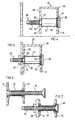
- FIG. 6 and 7Another example of a prior art latch design is disclosed in Figures 6 and 7.
- a sleeve 10is provided within a housing which may define a pivot point.
- the sleeve 10is be flared at either end to secure inner 12 and outer 14 plates to the housing.
- a bolt 16is then partially threaded into the slccvc 10 to retain the bolt 16 to the latch during shipping.
- the latchUpon arrival on the assembly line, the latch is presented to a mounting frame 18 of a vehicle and the bolt 16 is extended beyond the sleeve 10 to mount the housing as shown in Figure 7.
- This designis likewise advantageous in that separate pivot pins may not be required and the space occupied by the bolts 16 is utilized.
- This designrequires that the sleeve 10 be separately press fit to the housing to hold the inner 12 and outer 14 plates to the housing.
- the mounting bolts 16are separately mounted through to the sleeves 10.
- this designalso requires additional parts and manufacturing steps to make and mount the latch. Additionally, this fastening configuration is over designed for the rigors of shipping a typical latch from the manufacturing facility to a vehicle assembly plant.
- a latchincorporating an integral mounting pin which secures the plates and housing of the latch together, acts as a pivot point for interior latch components and also secures the latch to a vehicle. Further, the latch should not suffer from the deficiencies outlined above such that the latch is made of fewer parts and is easier to assemble and install.
- US 3,687,501relates to a fastener for securing a couple of panel members wherein one abuts against the other.
- the disadvantages of the prior artmay be overcome by providing a latch assembly according to claim 1.
- the latch assemblycomprises a latch housing having an inner side and an opposing outer side.
- An inner plateabuts the inner side and has at least one aperture.
- An outer platesimilarly abuts the outer side opposite the inner plate and has at least one aperture aligned with the aperture of the inner plate.
- At least one mounting pinhaving first and second distal ends, extends through the apertures.
- a headis disposed on the first distal end of the pin for abutting the outer plate.
- the assemblyis characterized by the mounting pin having an enlarged barrel portion extending from the head to a shoulder with the shoulder abutting the inner plate to orient the outer plate relative to the inner plate.
- the subject inventionincludes a mounting pin which can be a pivot point for the latch components, can hold the inner and outer plates against the housing and also provides mounting locations for the latch.
- the subject latch and pin assemblyholds the latch together for shipping and provides a fastening portion for securing the latch to a vehicle.
- the subject inventionis also of a compact design which is easily and efficiently manufactured and installed.
- a latch and mounting pin assemblyis generally shown at 20 in Figure 1.
- the latch assembly 20preferably has a design and configuration which defines a door latch suitable for securing a door of a vehicle (not shown).
- the subject inventionmay be utilized in various configurations to secure hatches, hoods, trunks and the like.
- the latch assembly 20comprises a latch housing 22 having an inner side 24 and an opposing outer side 26.
- inner and outerare relative terms which are used to preferably orient the subject housing 22 when the housing 22 is mounted to the vehicle.
- the housing 22may be positioned in any suitable orientation depending upon the particular vehicle manufacturer.
- An inner plate 28abuts the inner side 24 and has at least one aperture 30.
- an outer plate 32abuts the outer side 26 opposite the inner plate 28 and has at least one aperture 34 aligned with the aperture 30 of the inner plate 28.
- the terms inner and outerare purely illustrative of a preferred mounting orientation and are in no way intended to limit the subject application.
- the plates 28, 32are preferably oriented in opposing directions with the corresponding apertures being aligned.
- the inner plate 28is preferably an integral portion of the housing 22 which defines a cavity (not numbered) disposed within the housing 22.
- the outer plate 32acts as a cover for the cavity to encapsulate the housing 22.
- the inner 28 and outer 32 platesmay both be separable from the housing 22 such that the housing 22 is sandwiched between the inner 28 and outer 32 plates.
- a number of locking and releasing componentsare disposed within the cavity of the housing 22 to provide the operating characteristics of the latch and pin assembly 20.
- Some of the componentsmay include a primary ratchet, pawl, spring and the like as is known in the art.
- At least one mounting pin 36which has first and second distal ends, extends through a pair of aligned apertures 30, 34.
- the mounting pins 36interlock the inner 28 and outer 32 plates to the housing 22 to create a portable latch assembly 20.
- the pins 36may also act as pivot points for the primary and secondary latches, the pawl and other like components. The subject invention therefore creates a compact and portable assembly 20 which is self contained.
- each of the mounting pins 36is shown in greater detail.
- Each of the mounting pins 36are substantially identical. Hence, for illustrative purposes, only one pin 36 is shown and subsequently described.
- a head 38is disposed on the first distal end of the pin 36 for abutting the outer plate 32. As best shown in Figure 3, the head 38 of the pin 36 includes an axial recess 40 for receiving an installation tool (not shown).
- the mounting pin 36has an enlarged barrel portion 42 extending from the head 38 to a shoulder 44.
- the enlarged barrel portion 42has a diameter which is smaller than a diameter of the head 38.
- the barrel portion 42is also of a substantially uniform circular cross-section.
- the barrel portion 42includes a first locking section 46 disposed adjacent the head 38 for press fitting the barrel portion 42 into the aperture 34 of the outer plate 32, thereby securing the first distal end of the mounting pin 36 to the outer plate 32.
- the first locking section 46preferably comprises a plurality of axially extending ridges 46 disposed circumferentially around the barrel portion 42.
- the ridges 46maybe of any suitable size, width or number, so long as the first distal end of the pin 36 is adequately secured to the outer plate 32.
- a circumferential step 48is disposed adjacent the head 38 and has a diameter larger than a diameter of the barrel portion 42 with the ridges 46 disposed on the circumferential step 48.
- the aperture 34 in the outer plate 32is complementary in size to the circumferential size of the step 48.
- the mounting pin 36further includes a threaded shank 50 having a diameter less than that of the barrel portion 42 and extends from the shoulder 44 to the second distal end.
- the shank 50extends through the aperture 30 in the inner plate 28 and outwardly from the inner plate 28 to provide the mounting means for the latch assembly 20 to the vehicle.
- the threaded shank 50has a design similar to a machine threaded bolt with a non-threaded tip.
- the length, diameter, thread pitch, thread size and other like parameters of the shank 50may be of any suitable design to suit a particular application.
- a diameter of the aperture 30 within the inner plate 28is smaller than the diameter of the aperture 34 in the outer plate 32 due to the relative sizes of the shank 50 and barrel portion 42.
- a second locking section 52is disposed on the mounting pin 36 adjacent the shoulder 44 of the enlarged barrel portion 42 for securing the mounting pin 36 to the inner plate 28 as is discussed below.
- This first 46 and second 52 locking sectionswork in conjunction to continuously hold the inner 28 and outer 32 plates against the housing 22, which creates a portable interlocked latch pin assembly 20 as shown in Figure 1.
- the second locking section 52preferably comprises a locking flange 52 having a plurality of undulating projections.
- the undulating projectionsdefine a "flower petal" shaped locking flange 52.
- a diameter of the locking flange projectionsis smaller than the diameter of the barrel portion 42.
- the mounting pin 36is further illustrated with respect to the pin 36 being disposed within the housing 22.
- the shoulder 44 of the barrel portion 42abuts the inner plate 28 to orient the outer plate 32 relative to the inner plate 28.
- the enlarged barrel portion 42defines the depth of the cavity for the housing 22.
- the locking flange 52is spaced from the shoulder 44 of the barrel portion 42 to extend through the aperture 30 in the inner plate 28. Hence, the locking flange 52 abuts an exterior side of the inner plate 28 and the shoulder 44 engages an interior side of the inner plate 28 to further interlock the mounting pin 36 to the housing 22.
- the mounting pin 36is therefore secured to the housing 22 by being press fitted within the aperture 34 of the outer plate 32 and interlocked about the aperture 30 of the inner plate 28.
- the bias of the locking flange 52works with the head 38 in order to restrict axial movement along the mounting pin 36.
- the threaded shank 50passes through a corresponding aperture (not numbered) in a frame 54.
- the frame 54is a door frame such that the assembly 20 is utilized to secure the door to the vehicle.
- the subject inventionis not limited to being mounted to door frames 54 and any suitable portion of the vehicle may be utilized.
- a nut 56is threaded onto the threaded shank 50 to secure the housing 22 to the frame 54.
- the subject inventionprovides for a simplified installation procedure of the latch which does not require the use of separate bolts or the assembly of the latch housing 22.
Landscapes
- Engineering & Computer Science (AREA)
- General Engineering & Computer Science (AREA)
- Mechanical Engineering (AREA)
- Lock And Its Accessories (AREA)
- Braking Arrangements (AREA)
Abstract
Description
Claims (10)
- A latch assembly comprising:said assembly beingcharacterized in that said mounting pin (36) has a barrel portion (42)extending from said head (38) to a shoulder (44), said barrel portion (42) having adiameter greater than a diameter of said threaded portion (50) and less than a diameter ofsaid head (38), said barrel portion (42) presenting a pivot for a component of said latchassembly, said head (38) abutting said outer plate (32), and said mounting pin (36) havinga locking section (52) disposed adjacent said shoulder (44) of said barrel portion (42),said locking section (52) engaging said aligned aperture (30) of said inner plate (28) forsecuring said mounting pin (36) to said inner plate (28) and continuously holding saidinner and outer plates (28, 32) against said housing (22), thereby creating a portableinterlocked latch and mounting pin assembly.a latch housing (22) having an inner side (24) and an opposing outer side (26),an inner plate (28) abutting said inner side (24) and having at least one aperture(30),an outer plate (32) abutting said outer side (26) opposite said inner plate (28) andhaving at least one aperture (34) aligned with said aperture (30) of said inner plate(28),at least one mounting pin (36) having first and second distal ends extendingthrough said axially aligned apertures (30, 34) of said inner and outer plates (28,32), anda head (38) disposed on said first distal end of said pin (36) and a threaded portion(50) on said second distal end,
- An assembly as claimed in claim 1, wherein said mounting pin (36) further includes asmaller diameter threaded shank (50) extending from said shoulder (44) to said seconddistal end.
- An assembly as claimed in claim 2, wherein said barrel portion (42) includes a furtherlocking section (46) disposed adjacent said head (38) for press fitting said barrel portion(42) into said aperture (34) of said outer plate (32).
- An assembly as claimed in claim 3, wherein said further locking section (46)comprises a plurality of outwardly extending ridges disposed circumferentially aroundsaid barrel portion (42).
- An assembly as claimed in claim 4, further including a circumferential step (48)disposed adjacent said head (38) and having a diameter larger than a diameter of saidbarrel portion (42) with said ridges disposed on said circumferential step (48).
- An assembly as claimed in claim 3, wherein said locking section (52) is press fittedinto said aligned aperture (30) of said inner plate (28).
- An assembly as claimed in claim 6, wherein said locking section (52) comprises alocking flange (52) having a plurality of undulating projections.
- An assembly as claimed in claim 7, wherein said locking flange (52) is spaced fromsaid shoulder (44) of said barrel portion (42) to extend through said aperture (30) in saidinner plate (28) such that said locking flange (52) abuts an exterior side of said inner plate(28) and said shoulder (44) abuts an interior side of said inner plate (28) to furtherinterlock said mounting pin (36) to said housing (22).
- An assembly as claimed in claim 8, wherein a diameter of said locking flange (52) issmaller than a diameter of said barrel portion (42).
- An assembly as claimed in claim 6, wherein said inner plate (28) has three saidapertures (30) and said outer plate (32) has three said apertures (34) aligned with saidthree apertures (30) of said inner plate (28), said assembly comprising three saidmounting pin (36) each having first and second distal ends extending throughcorresponding apertures (30, 34) of said inner and outer plates (28, 32).
Applications Claiming Priority (3)
| Application Number | Priority Date | Filing Date | Title |
|---|---|---|---|
| US11800599P | 1999-02-01 | 1999-02-01 | |
| US118005P | 1999-02-01 | ||
| PCT/CA2000/000090WO2000046471A1 (en) | 1999-02-01 | 2000-02-01 | Staking and mounting pin for a vehicle door latch |
Publications (2)
| Publication Number | Publication Date |
|---|---|
| EP1149219A1 EP1149219A1 (en) | 2001-10-31 |
| EP1149219B1true EP1149219B1 (en) | 2004-04-21 |
Family
ID=22375995
Family Applications (1)
| Application Number | Title | Priority Date | Filing Date |
|---|---|---|---|
| EP00902512AExpired - LifetimeEP1149219B1 (en) | 1999-02-01 | 2000-02-01 | Staking and mounting pin for a vehicle door latch |
Country Status (10)
| Country | Link |
|---|---|
| US (1) | US6601885B1 (en) |
| EP (1) | EP1149219B1 (en) |
| AT (1) | ATE264975T1 (en) |
| AU (1) | AU2426200A (en) |
| BR (1) | BR0007859A (en) |
| CA (1) | CA2355086C (en) |
| CZ (1) | CZ20012704A3 (en) |
| DE (1) | DE60010044T2 (en) |
| PL (1) | PL349071A1 (en) |
| WO (1) | WO2000046471A1 (en) |
Families Citing this family (19)
| Publication number | Priority date | Publication date | Assignee | Title |
|---|---|---|---|---|
| DE202004005460U1 (en)* | 2004-04-07 | 2005-09-01 | Alfit Ag | Fastener for furniture fittings |
| US7159289B1 (en) | 2004-05-20 | 2007-01-09 | Ankara Industries, Inc. | Fastener forming apparatus and method for making a fastener of metal |
| US8899867B2 (en)* | 2011-03-02 | 2014-12-02 | Wally Wayne Tatomir | Mounting assembly for a face shield |
| ITTO20130194A1 (en) | 2013-03-12 | 2014-09-13 | Proma S P A | CLOSING LOCK IN PARTICULAR FOR A RECLINABLE BACKREST OF A SEAT OF A VEHICLE. |
| JP6024023B2 (en)* | 2013-04-25 | 2016-11-09 | 三井金属アクト株式会社 | Vehicle door latch device |
| US20150078860A1 (en)* | 2013-09-17 | 2015-03-19 | Jeffrey S. Ellingson | Apparatus for Mounting Enclosures and Fixtures and Electronics Contained Therein |
| US10077794B2 (en) | 2013-09-17 | 2018-09-18 | Jeffrey S. Ellingson | Apparatus for mounting enclosures and fixtures and electronics contained therein |
| CA2938844A1 (en)* | 2015-08-14 | 2017-02-14 | Wally Wayne Tatomir | Mounting assembly for a face shield with an enhanced base |
| NO343801B1 (en) | 2016-02-17 | 2019-06-11 | Qinterra Tech As | Downhole tractor comprising a hydraulic supply line for actuating hydraulic components |
| CN107620529B (en) | 2016-07-15 | 2020-12-15 | 株式会社安成 | Door lock device for vehicle |
| JP6627672B2 (en) | 2016-07-20 | 2020-01-08 | 株式会社アンセイ | Vehicle door lock device |
| JP6627729B2 (en) | 2016-11-25 | 2020-01-08 | 株式会社アンセイ | Vehicle door lock device |
| US11149477B2 (en) | 2017-06-28 | 2021-10-19 | Snap-On Incorporated | Latch and method of installing a latch |
| US10995789B2 (en)* | 2017-09-06 | 2021-05-04 | Awi Licensing Llc | Multi-featured panel fastener and panel system including the multi-featured panel fastener |
| JP6627920B2 (en) | 2018-06-26 | 2020-01-08 | 株式会社アンセイ | Vehicle door lock device |
| US11566453B2 (en)* | 2019-06-17 | 2023-01-31 | GM Global Technology Operations LLC | Striker mounted endgate damper |
| DE102019131176A1 (en)* | 2019-11-19 | 2021-05-20 | Kiekert Aktiengesellschaft | Motor vehicle lock, in particular motor vehicle door lock |
| DE102020131515A1 (en)* | 2020-11-27 | 2022-06-02 | Fujitsu Client Computing Limited | Screw with guide means |
| JP2023178877A (en) | 2022-06-06 | 2023-12-18 | 株式会社アンセイ | Vehicle opening/closing body locking device |
Family Cites Families (14)
| Publication number | Priority date | Publication date | Assignee | Title |
|---|---|---|---|---|
| GB400108A (en)* | 1932-04-08 | 1933-10-19 | Dardelet Threadlock Corp | Improvements in fastening means |
| US3572797A (en)* | 1969-04-17 | 1971-03-30 | L W Menziner Trustee | Striker for use with a vehicle latch |
| US3687501A (en)* | 1969-12-31 | 1972-08-29 | Charles A Wilson | Non-rotatable fastener |
| JPS57184169A (en)* | 1981-05-06 | 1982-11-12 | Ohi Seisakusho Co Ltd | Inside handle apparatus of automobile door |
| US4639023A (en)* | 1985-05-30 | 1987-01-27 | Richard Boisvert | Pivotable locking bar for patio doors |
| US4880262A (en)* | 1987-03-02 | 1989-11-14 | Frank A. Mugnolo | Door latch |
| FR2623840B1 (en)* | 1987-12-01 | 1994-01-14 | Thirard Ets | FIXING DEVICE FOR A LOCK, A LATCH OR THE LIKE ON A SUPPORT SUCH AS A DOOR LEAF, PROVIDING IMPROVED RESISTANCE TO THE PULLING |
| JP2552204B2 (en)* | 1991-03-26 | 1996-11-06 | 三井金属鉱業株式会社 | Frame of lock device for trunk door |
| DE4203153A1 (en)* | 1992-02-05 | 1993-07-08 | Schuermann & Hilleke Gmbh | Bolt for fastening workpieces together - is retained in one workpiece by groove into which metal is forced from workpiece |
| US5348357A (en)* | 1992-12-24 | 1994-09-20 | General Motors Corporation | Vehicle closure latch having plastic coated ratchet |
| US5538150A (en)* | 1995-02-01 | 1996-07-23 | Dur-A-Lift, Inc. | Boom latch |
| KR0184356B1 (en)* | 1996-10-28 | 2002-02-28 | 동양기전 주식회사 | Locking device |
| US5863069A (en)* | 1997-04-15 | 1999-01-26 | Ford Global Technologies, Inc. | Energy absorbing sling assembly |
| US5787794A (en)* | 1997-06-17 | 1998-08-04 | Indian Head Industries, Inc. | Mounting bolt for brake actuator |
- 2000
- 2000-02-01CACA002355086Apatent/CA2355086C/ennot_activeExpired - Fee Related
- 2000-02-01AUAU24262/00Apatent/AU2426200A/ennot_activeAbandoned
- 2000-02-01ATAT00902512Tpatent/ATE264975T1/ennot_activeIP Right Cessation
- 2000-02-01EPEP00902512Apatent/EP1149219B1/ennot_activeExpired - Lifetime
- 2000-02-01PLPL00349071Apatent/PL349071A1/enunknown
- 2000-02-01DEDE60010044Tpatent/DE60010044T2/ennot_activeExpired - Lifetime
- 2000-02-01USUS09/890,603patent/US6601885B1/ennot_activeExpired - Fee Related
- 2000-02-01CZCZ20012704Apatent/CZ20012704A3/enunknown
- 2000-02-01WOPCT/CA2000/000090patent/WO2000046471A1/enactiveIP Right Grant
- 2000-02-01BRBR0007859-0Apatent/BR0007859A/ennot_activeIP Right Cessation
Also Published As
| Publication number | Publication date |
|---|---|
| US6601885B1 (en) | 2003-08-05 |
| CA2355086C (en) | 2008-05-20 |
| PL349071A1 (en) | 2002-07-01 |
| DE60010044D1 (en) | 2004-05-27 |
| WO2000046471A1 (en) | 2000-08-10 |
| CZ20012704A3 (en) | 2002-06-12 |
| EP1149219A1 (en) | 2001-10-31 |
| AU2426200A (en) | 2000-08-25 |
| CA2355086A1 (en) | 2000-08-10 |
| ATE264975T1 (en) | 2004-05-15 |
| BR0007859A (en) | 2001-10-23 |
| DE60010044T2 (en) | 2005-04-28 |
Similar Documents
| Publication | Publication Date | Title |
|---|---|---|
| EP1149219B1 (en) | Staking and mounting pin for a vehicle door latch | |
| CA2441024C (en) | Fastener for attaching panels to a vehicle | |
| US5203441A (en) | Adaptor for use in a flywheel and transmission assembly | |
| EP0898087B1 (en) | Fastening assembly for fastening a first member to a second member | |
| US5046770A (en) | Bar lock module and assembly system | |
| KR100412833B1 (en) | A non housing grip type door handle and assembling process of the same | |
| US20050164821A1 (en) | Motor vehicle differential | |
| US5335525A (en) | Universal adaptor for deadbolt | |
| US5951046A (en) | Construction for attaching a seat belt adjuster | |
| US7096845B1 (en) | Captured nut using a stamped retention feature | |
| US6412319B1 (en) | Lockset having keyed egg-shaped knob | |
| KR100743577B1 (en) | Ball Joint Fastening Structure of Gas Spring | |
| JPH07127623A (en) | Structure of fixtures for exterior parts | |
| MXPA01007744A (en) | Staking and mounting pin for a vehicle door latch | |
| EP1055593A2 (en) | U-shaped antitheft device | |
| EP3405365B1 (en) | Fastening construction for fastening an adjustment instrument for an exterior vision element, such as an exterior mirror, camera and/or display, to a carrying frame of an exterior vision unit of a motor vehicle, and exterior vision unit | |
| JP3972284B2 (en) | Key cylinder mounting structure | |
| JP4552325B2 (en) | Vehicle door handle device | |
| KR0134515Y1 (en) | Internal and external diameter stop ring | |
| JP2552620Y2 (en) | Key cylinder mounting device for vehicle lid | |
| ES2328357T3 (en) | DOOR LOCK AND PROCEDURE FOR MANUFACTURING SUCH DOOR LOCK. | |
| JP2001323690A (en) | Cylinder lock installation structure in vehicle door | |
| KR0132048Y1 (en) | Automotive Castle Nuts | |
| US20220127876A1 (en) | Interior Handle for Upward Acting Vehicle Door | |
| JPH0579030U (en) | nut |
Legal Events
| Date | Code | Title | Description |
|---|---|---|---|
| PUAI | Public reference made under article 153(3) epc to a published international application that has entered the european phase | Free format text:ORIGINAL CODE: 0009012 | |
| 17P | Request for examination filed | Effective date:20010731 | |
| AK | Designated contracting states | Kind code of ref document:A1 Designated state(s):AT BE CH CY DE DK ES FI FR GB GR IE IT LI LU MC NL PT SE | |
| AX | Request for extension of the european patent | Free format text:AL;LT;LV;MK;RO;SI | |
| 17Q | First examination report despatched | Effective date:20020613 | |
| RAP1 | Party data changed (applicant data changed or rights of an application transferred) | Owner name:INTIER AUTOMOTIVE CLOSURES INC. | |
| GRAP | Despatch of communication of intention to grant a patent | Free format text:ORIGINAL CODE: EPIDOSNIGR1 | |
| GRAS | Grant fee paid | Free format text:ORIGINAL CODE: EPIDOSNIGR3 | |
| GRAA | (expected) grant | Free format text:ORIGINAL CODE: 0009210 | |
| AK | Designated contracting states | Kind code of ref document:B1 Designated state(s):AT BE CH CY DE DK ES FI FR GB GR IE IT LI LU MC NL PT SE | |
| PG25 | Lapsed in a contracting state [announced via postgrant information from national office to epo] | Ref country code:CH Free format text:LAPSE BECAUSE OF FAILURE TO SUBMIT A TRANSLATION OF THE DESCRIPTION OR TO PAY THE FEE WITHIN THE PRESCRIBED TIME-LIMIT Effective date:20040421 Ref country code:FI Free format text:LAPSE BECAUSE OF FAILURE TO SUBMIT A TRANSLATION OF THE DESCRIPTION OR TO PAY THE FEE WITHIN THE PRESCRIBED TIME-LIMIT Effective date:20040421 Ref country code:AT Free format text:LAPSE BECAUSE OF FAILURE TO SUBMIT A TRANSLATION OF THE DESCRIPTION OR TO PAY THE FEE WITHIN THE PRESCRIBED TIME-LIMIT Effective date:20040421 Ref country code:NL Free format text:LAPSE BECAUSE OF FAILURE TO SUBMIT A TRANSLATION OF THE DESCRIPTION OR TO PAY THE FEE WITHIN THE PRESCRIBED TIME-LIMIT Effective date:20040421 Ref country code:LI Free format text:LAPSE BECAUSE OF FAILURE TO SUBMIT A TRANSLATION OF THE DESCRIPTION OR TO PAY THE FEE WITHIN THE PRESCRIBED TIME-LIMIT Effective date:20040421 Ref country code:BE Free format text:LAPSE BECAUSE OF FAILURE TO SUBMIT A TRANSLATION OF THE DESCRIPTION OR TO PAY THE FEE WITHIN THE PRESCRIBED TIME-LIMIT Effective date:20040421 | |
| REG | Reference to a national code | Ref country code:GB Ref legal event code:FG4D | |
| REG | Reference to a national code | Ref country code:CH Ref legal event code:EP | |
| REG | Reference to a national code | Ref country code:IE Ref legal event code:FG4D | |
| REF | Corresponds to: | Ref document number:60010044 Country of ref document:DE Date of ref document:20040527 Kind code of ref document:P | |
| PG25 | Lapsed in a contracting state [announced via postgrant information from national office to epo] | Ref country code:GR Free format text:LAPSE BECAUSE OF FAILURE TO SUBMIT A TRANSLATION OF THE DESCRIPTION OR TO PAY THE FEE WITHIN THE PRESCRIBED TIME-LIMIT Effective date:20040721 Ref country code:SE Free format text:LAPSE BECAUSE OF FAILURE TO SUBMIT A TRANSLATION OF THE DESCRIPTION OR TO PAY THE FEE WITHIN THE PRESCRIBED TIME-LIMIT Effective date:20040721 Ref country code:DK Free format text:LAPSE BECAUSE OF FAILURE TO SUBMIT A TRANSLATION OF THE DESCRIPTION OR TO PAY THE FEE WITHIN THE PRESCRIBED TIME-LIMIT Effective date:20040721 | |
| PG25 | Lapsed in a contracting state [announced via postgrant information from national office to epo] | Ref country code:ES Free format text:LAPSE BECAUSE OF FAILURE TO SUBMIT A TRANSLATION OF THE DESCRIPTION OR TO PAY THE FEE WITHIN THE PRESCRIBED TIME-LIMIT Effective date:20040801 | |
| NLV1 | Nl: lapsed or annulled due to failure to fulfill the requirements of art. 29p and 29m of the patents act | ||
| REG | Reference to a national code | Ref country code:CH Ref legal event code:PL | |
| ET | Fr: translation filed | ||
| PG25 | Lapsed in a contracting state [announced via postgrant information from national office to epo] | Ref country code:CY Free format text:LAPSE BECAUSE OF FAILURE TO SUBMIT A TRANSLATION OF THE DESCRIPTION OR TO PAY THE FEE WITHIN THE PRESCRIBED TIME-LIMIT Effective date:20050201 Ref country code:LU Free format text:LAPSE BECAUSE OF NON-PAYMENT OF DUE FEES Effective date:20050201 Ref country code:IE Free format text:LAPSE BECAUSE OF NON-PAYMENT OF DUE FEES Effective date:20050201 | |
| PLBE | No opposition filed within time limit | Free format text:ORIGINAL CODE: 0009261 | |
| STAA | Information on the status of an ep patent application or granted ep patent | Free format text:STATUS: NO OPPOSITION FILED WITHIN TIME LIMIT | |
| PG25 | Lapsed in a contracting state [announced via postgrant information from national office to epo] | Ref country code:MC Free format text:LAPSE BECAUSE OF NON-PAYMENT OF DUE FEES Effective date:20050228 | |
| 26N | No opposition filed | Effective date:20050124 | |
| REG | Reference to a national code | Ref country code:IE Ref legal event code:MM4A | |
| PG25 | Lapsed in a contracting state [announced via postgrant information from national office to epo] | Ref country code:PT Free format text:LAPSE BECAUSE OF NON-PAYMENT OF DUE FEES Effective date:20040921 | |
| PGFP | Annual fee paid to national office [announced via postgrant information from national office to epo] | Ref country code:IT Payment date:20120215 Year of fee payment:13 | |
| PGFP | Annual fee paid to national office [announced via postgrant information from national office to epo] | Ref country code:DE Payment date:20130131 Year of fee payment:14 Ref country code:FR Payment date:20130301 Year of fee payment:14 Ref country code:GB Payment date:20130130 Year of fee payment:14 | |
| REG | Reference to a national code | Ref country code:DE Ref legal event code:R119 Ref document number:60010044 Country of ref document:DE | |
| GBPC | Gb: european patent ceased through non-payment of renewal fee | Effective date:20140201 | |
| REG | Reference to a national code | Ref country code:FR Ref legal event code:ST Effective date:20141031 | |
| REG | Reference to a national code | Ref country code:DE Ref legal event code:R119 Ref document number:60010044 Country of ref document:DE Effective date:20140902 | |
| PG25 | Lapsed in a contracting state [announced via postgrant information from national office to epo] | Ref country code:DE Free format text:LAPSE BECAUSE OF NON-PAYMENT OF DUE FEES Effective date:20140902 Ref country code:FR Free format text:LAPSE BECAUSE OF NON-PAYMENT OF DUE FEES Effective date:20140228 Ref country code:GB Free format text:LAPSE BECAUSE OF NON-PAYMENT OF DUE FEES Effective date:20140201 | |
| PG25 | Lapsed in a contracting state [announced via postgrant information from national office to epo] | Ref country code:IT Free format text:LAPSE BECAUSE OF NON-PAYMENT OF DUE FEES Effective date:20140201 |