EP1148836B1 - Custom tray for delivering medication to oral structures - Google Patents
Custom tray for delivering medication to oral structuresDownload PDFInfo
- Publication number
- EP1148836B1 EP1148836B1EP99967627AEP99967627AEP1148836B1EP 1148836 B1EP1148836 B1EP 1148836B1EP 99967627 AEP99967627 AEP 99967627AEP 99967627 AEP99967627 AEP 99967627AEP 1148836 B1EP1148836 B1EP 1148836B1
- Authority
- EP
- European Patent Office
- Prior art keywords
- model
- sheet member
- act
- trimming
- gingival
- Prior art date
- Legal status (The legal status is an assumption and is not a legal conclusion. Google has not performed a legal analysis and makes no representation as to the accuracy of the status listed.)
- Expired - Lifetime
Links
- 229940079593drugDrugs0.000titleclaimsdescription62
- 239000003814drugSubstances0.000titleclaimsdescription62
- 210000002455dental archAnatomy0.000claimsdescription31
- 238000009966trimmingMethods0.000claimsdescription22
- 238000004519manufacturing processMethods0.000claimsdescription17
- 210000004195gingivaAnatomy0.000claimsdescription7
- 230000003247decreasing effectEffects0.000claimsdescription2
- 230000007423decreaseEffects0.000claims1
- 238000000034methodMethods0.000description20
- 239000000463materialSubstances0.000description18
- 238000004061bleachingMethods0.000description14
- 239000007844bleaching agentSubstances0.000description13
- 239000002390adhesive tapeSubstances0.000description10
- 210000001519tissueAnatomy0.000description9
- AQLJVWUFPCUVLO-UHFFFAOYSA-Nurea hydrogen peroxideChemical compoundOO.NC(N)=OAQLJVWUFPCUVLO-UHFFFAOYSA-N0.000description9
- 239000000243solutionSubstances0.000description7
- 210000000214mouthAnatomy0.000description6
- 210000003296salivaAnatomy0.000description6
- 239000012815thermoplastic materialSubstances0.000description6
- 241000264877Hippospongia communisSpecies0.000description5
- 239000005038ethylene vinyl acetateSubstances0.000description5
- DQXBYHZEEUGOBF-UHFFFAOYSA-Nbut-3-enoic acid;etheneChemical compoundC=C.OC(=O)CC=CDQXBYHZEEUGOBF-UHFFFAOYSA-N0.000description4
- 229940078916carbamide peroxideDrugs0.000description4
- 238000005266castingMethods0.000description4
- 229920001200poly(ethylene-vinyl acetate)Polymers0.000description4
- -1polypropylene, ethylenePolymers0.000description4
- XLYOFNOQVPJJNP-UHFFFAOYSA-NwaterSubstancesOXLYOFNOQVPJJNP-UHFFFAOYSA-N0.000description4
- PEDCQBHIVMGVHV-UHFFFAOYSA-NGlycerineChemical compoundOCC(O)COPEDCQBHIVMGVHV-UHFFFAOYSA-N0.000description3
- DNIAPMSPPWPWGF-UHFFFAOYSA-NPropylene glycolChemical compoundCC(O)CODNIAPMSPPWPWGF-UHFFFAOYSA-N0.000description3
- 230000009471actionEffects0.000description3
- 239000000853adhesiveSubstances0.000description3
- 230000001070adhesive effectEffects0.000description3
- 230000008901benefitEffects0.000description3
- 210000003467cheekAnatomy0.000description3
- 230000000694effectsEffects0.000description3
- 239000000203mixtureSubstances0.000description3
- 238000000465mouldingMethods0.000description3
- 238000005086pumpingMethods0.000description3
- FHVDTGUDJYJELY-UHFFFAOYSA-N6-{[2-carboxy-4,5-dihydroxy-6-(phosphanyloxy)oxan-3-yl]oxy}-4,5-dihydroxy-3-phosphanyloxane-2-carboxylic acidChemical compoundO1C(C(O)=O)C(P)C(O)C(O)C1OC1C(C(O)=O)OC(OP)C(O)C1OFHVDTGUDJYJELY-UHFFFAOYSA-N0.000description2
- 239000004480active ingredientSubstances0.000description2
- 229940072056alginateDrugs0.000description2
- 229920000615alginic acidPolymers0.000description2
- 235000010443alginic acidNutrition0.000description2
- 210000004763bicuspidAnatomy0.000description2
- 210000003298dental enamelAnatomy0.000description2
- 210000003128headAnatomy0.000description2
- 239000004033plasticSubstances0.000description2
- 229920003023plasticPolymers0.000description2
- 229920000139polyethylene terephthalatePolymers0.000description2
- 239000005020polyethylene terephthalateSubstances0.000description2
- 210000004872soft tissueAnatomy0.000description2
- 238000012360testing methodMethods0.000description2
- 239000011800void materialSubstances0.000description2
- NCVGSSQICKMAIA-UHFFFAOYSA-N2-heptadecyl-4,5-dihydro-1h-imidazoleChemical compoundCCCCCCCCCCCCCCCCCC1=NCCN1NCVGSSQICKMAIA-UHFFFAOYSA-N0.000description1
- NIXOWILDQLNWCW-UHFFFAOYSA-NAcrylic acidChemical groupOC(=O)C=CNIXOWILDQLNWCW-UHFFFAOYSA-N0.000description1
- 241000587161GomphocarpusSpecies0.000description1
- 241001313288LabiaSpecies0.000description1
- 235000014676Phragmites communisNutrition0.000description1
- 239000004743PolypropyleneSubstances0.000description1
- 229920002125Sokalan®Polymers0.000description1
- 239000004098TetracyclineSubstances0.000description1
- XTXRWKRVRITETP-UHFFFAOYSA-NVinyl acetateChemical compoundCC(=O)OC=CXTXRWKRVRITETP-UHFFFAOYSA-N0.000description1
- 238000005299abrasionMethods0.000description1
- 238000007792additionMethods0.000description1
- 230000002421anti-septic effectEffects0.000description1
- 238000013459approachMethods0.000description1
- 230000009286beneficial effectEffects0.000description1
- 235000013361beverageNutrition0.000description1
- 230000015572biosynthetic processEffects0.000description1
- 229940096529carboxypolymethyleneDrugs0.000description1
- 230000006835compressionEffects0.000description1
- 238000007906compressionMethods0.000description1
- 238000011960computer-aided designMethods0.000description1
- 238000010276constructionMethods0.000description1
- 238000007796conventional methodMethods0.000description1
- 210000003464cuspidAnatomy0.000description1
- 230000004069differentiationEffects0.000description1
- 238000007865dilutingMethods0.000description1
- 230000003292diminished effectEffects0.000description1
- 238000002845discolorationMethods0.000description1
- 230000002708enhancing effectEffects0.000description1
- 230000001815facial effectEffects0.000description1
- 235000013305foodNutrition0.000description1
- 229940026651gly-oxideDrugs0.000description1
- 230000006872improvementEffects0.000description1
- 210000004283incisorAnatomy0.000description1
- 230000007794irritationEffects0.000description1
- 210000000088lipAnatomy0.000description1
- 230000014759maintenance of locationEffects0.000description1
- 235000012054mealsNutrition0.000description1
- 238000002483medicationMethods0.000description1
- 239000008368mint flavorSubstances0.000description1
- 238000012986modificationMethods0.000description1
- 230000004048modificationEffects0.000description1
- 210000003254palateAnatomy0.000description1
- 230000000737periodic effectEffects0.000description1
- 230000002093peripheral effectEffects0.000description1
- 239000002985plastic filmSubstances0.000description1
- 229920001155polypropylenePolymers0.000description1
- 229920001296polysiloxanePolymers0.000description1
- 230000008569processEffects0.000description1
- 238000011160researchMethods0.000description1
- 238000012552reviewMethods0.000description1
- 239000011435rockSubstances0.000description1
- 229960002180tetracyclineDrugs0.000description1
- 229930101283tetracyclineNatural products0.000description1
- 235000019364tetracyclineNutrition0.000description1
- 150000003522tetracyclinesChemical class0.000description1
- 235000019505tobacco productNutrition0.000description1
- 238000002834transmittanceMethods0.000description1
- LENZDBCJOHFCAS-UHFFFAOYSA-NtrisChemical compoundOCC(N)(CO)COLENZDBCJOHFCAS-UHFFFAOYSA-N0.000description1
- 238000007666vacuum formingMethods0.000description1
- 230000000007visual effectEffects0.000description1
- 230000002087whitening effectEffects0.000description1
Images
Classifications
- A—HUMAN NECESSITIES
- A61—MEDICAL OR VETERINARY SCIENCE; HYGIENE
- A61C—DENTISTRY; APPARATUS OR METHODS FOR ORAL OR DENTAL HYGIENE
- A61C19/00—Dental auxiliary appliances
- A61C19/06—Implements for therapeutic treatment
- A61C19/063—Medicament applicators for teeth or gums, e.g. treatment with fluorides
- A61C19/066—Bleaching devices; Whitening agent applicators for teeth, e.g. trays or strips
- B—PERFORMING OPERATIONS; TRANSPORTING
- B33—ADDITIVE MANUFACTURING TECHNOLOGY
- B33Y—ADDITIVE MANUFACTURING, i.e. MANUFACTURING OF THREE-DIMENSIONAL [3-D] OBJECTS BY ADDITIVE DEPOSITION, ADDITIVE AGGLOMERATION OR ADDITIVE LAYERING, e.g. BY 3-D PRINTING, STEREOLITHOGRAPHY OR SELECTIVE LASER SINTERING
- B33Y80/00—Products made by additive manufacturing
Definitions
- the present inventionrelates to a tray for delivering medication to the teeth and/or gingiva of a dental patient as for example disclosed in US 5 234 342 and US 5 573 399. More particularly, the field of the present invention concerns a dental medication delivery tray that is custom-made to closely match the configuration of at least part of a patient's dental arch.
- a variety of methodshave been proposed in the past to deliver medication to the teeth and/or gingiva (i.e., the gum tissue) of a dental patient.
- One method of applying medication to teethinvolves direct application of the medication to the tooth surface by the use of a brush, swab or the like. This method is relatively inexpensive and can be carried out either by the dental practitioner or by the patient.
- the direct application of a medicant to oral structuresis generally unsatisfactory because the medication typically does not remain on the oral structure for a significant length of time.
- the length of timeis variable and may depend on factors such as the viscosity of the medication, the presence of saliva and the ability of the patient to prevent adjacent soft tissues such as inner surfaces of the labia or lips and bucca or cheeks from contacting the tray containing the medication.
- the effectiveness of the medicationis substantially diminished if the medication is prematurely removed from the oral structure under treatment.
- the trayhas a channel that receives the teeth and has a length that is sufficient to receive all or at least a portion of the dental arch. In some instances, the channel has a sufficient depth to receive a portion of the gingiva along with the teeth.
- dental medication delivery traysare mass-produced and not custom made to closely fit the dental arch of a particular patient. Although such trays are relatively inexpensive, they are often considered quite bulky and unpleasant to wear for any significant length of time. Additionally, some mass-produced dental trays do not retain medication against the oral structures under treatment unless the patient remains relatively immobile.
- Dental trays that are custom-made to closely fit the dental arch of a patientare considered by many to represent a significant improvement over mass-produced dental trays.
- the close fit provided by custom-made trayslargely avoids unnecessary void spaces that are common with mass-produced dental trays.
- Most custom-made traysare less obtrusive in the mouth than mass-produced trays, and as such are more comfortable to wear for extended periods of time.
- One technique of making a custom dental trayinvolves taking an alginate impression of a patient's dental structure, and then making a model or casting from the impression. Next, a thin sheet of heat softenable plastic material is placed over the casting and heated, causing the plastic sheet to drape over the model and ultimately form a configuration that closely matches the shape of the underlying model. The tray is then trimmed as needed.
- Tooth stainsare caused by a variety of sources, including food and beverages, drugs (such as tetracycline), tobacco products and poor oral hygiene.
- the patientWhen dental trays are used for bleaching teeth at home, the patient is typically instructed to place an amount of bleaching solution into a corresponding area of the tray for each tooth to be treated. The tray is then placed over the dental arch. Often, the bleaching solution is changed every 0.5 to 2.5 hours and the tray is removed during meals. Sometimes a recommendation is made to wear the dental tray overnight.
- the efficacy of the bleaching proceduredepends on factors such as the type and intensity of the stain, the bleaching agent contact time on the tooth surfaces, the amount of available active ingredient in the bleaching solution as well as patient acceptance and adherence to the procedure.
- the present inventionis directed in one aspect to a custom-made medication delivery tray for delivering medication to tooth structure of a dental patient.
- the traycomprises a body having a base, a buccolabial wall and a lingual wall.
- the base, the buccolabial wall and the lingual wallpresent a channel that is generally complemental in configuration to the patient's tooth structure.
- the buccolabial wallextends at least in part along the gingival margin of the buccolabial side of the tooth structure without contacting the gingiva.
- the lingual wallextends along a line that is spaced at least in part at least 4 mm. in a gingival direction from the gingival margin of the tooth structure on a lingual side of the tooth structure.
- Another aspect of the present inventionrelates to a method of making a medication delivery tray for delivering medication to the dental structure of a patient.
- the methodcomprises the acts of providing a model of at least a portion of a dental arch, and forming a sheet member over at least part of the model.
- the methodalso includes the act of trimming the sheet member to make the tray.
- the act of trimming the sheet memberincludes the act of trimming the sheet member along a path corresponding to a line spaced no greater than 2.0 mm in an occlusal direction from the gingival margin of the model on a buccolabial side of the model.
- the act of trimming the sheet memberalso includes the act of trimming the sheet member along a path corresponding to a line that is spaced at least in part at least 4 mm. in a gingival direction from the gingival margin of the model on a lingual side of the model.
- the present inventionhas been found to significantly enhance retention of medication such as bleaching solution in the tray in comparison to conventional trays.
- the section of the lingual wall of the tray that extends past the gingival marginprovides an effective seal that resists movement of the medication in a direction from a lingual side to a buccolabial side of the arch and ultimately out over the gingival edge of the tray along the buccolabial wall.
- a comfortable areais presented to receive the patient's tongue and it is less likely that the tongue will engage the edge of the lingual wall and urge the tray away from the arch.
- the lingual extensionalso provides better stability of the tray in use so that the tray does not substantially rock or shift relative to the underlying arch.
- a custom-made medication delivery tray for delivering medication to tooth structure of a dental patientis illustrated in Fig. 1 and is broadly designated by the numeral 10.
- the trayincludes a body 12 having a base 14, a buccolabial wall 16 (i.e., a wall next to the patient's lips or cheeks) and a lingual wall 18 (i.e., a wall next to the patient's tongue).
- the base 14 and the walls 16, 18combine to present an elongated channel 20.
- the channel 20has an overall, generally "U”-shaped configuration in reference planes perpendicular to the longitudinal axis of the channel 20.
- the body 12 as well as the channel 20have an overall, generally "U”-shaped configuration in plan view or when considered in a reference plane containing the longitudinal axis of the channel 20.
- the body 12extends a distance equivalent to the entire length of the patient's arch or at least a substantial majority of the length of the patient's dental arch, although other constructions are also possible.
- the tray 10 and the channel 20may extend along only the patient's anterior teeth, or only along one quadrant of one dental arch.
- the channel 20is generally complemental in configuration to the patient's dental arch so that unnecessary void spaces between the tray and the patient's oral structures are avoided and the resulting tray is not considered obtrusive when worn in the mouth.
- small recesses or wells 21may be made along the inner surface of the buccolabial wall 16 adjacent the facial surface of each tooth in order to provide a pocket for receiving a quantity of the medication.
- the wells 21are provided only along the patient's anterior, cuspid and bicuspid teeth as may be useful, for example, when the tray 10 is used for delivering a bleaching composition to the most visible teeth.
- the lingual wall 18includes a peripheral edge section 22.
- the edge section 22has an outer edge 24 that extends along a line that is spaced at least in part and preferably spaced along substantially its entire length at least 4 mm. in a gingival direction from the gingival margin of the lingual side of the patient's dental arch receiving the tray 10. More preferably, the outer edge 24 extends along a line that is spaced at least in part (and more preferably is spaced substantially along its entire length) a distance of 6 mm. in a gingival direction from the gingival margin of the patient's dental arch along its lingual side.
- the edge 24is spaced no greater than 20 mm. and more preferably less than 12 mm. in a gingival direction at any point from the gingival margin of the lingual side of the dental arch.
- the preferred spacing of the edge 24 from the gingival margin along the lingual side of the dental arch as mentioned in the previous paragraphis provided at least in regions adjacent the patient's anterior teeth (i.e., in regions adjacent the patient's central and lateral incisors).
- the edge 24approaches the gingival margin and the edge section 22 narrows in width as either end of the channel 20 is approached.
- the edge 24may be as close as 2 mm., or optionally directly adjacent the patient's gingival margin in regions next to the patient's molar teeth.
- the tray 10 when made to fit the upper archincludes palatal section that extends across a majority of the patient's palate and is integrally connected to the lingual wall 18. In that instance the outer edge is spaced a distance greater than 12 mm. from the gingival margin at least in regions next to the anterior teeth.
- the buccolabial wall 16has an outer edge 26 that extends along the gingival margin of the patient's dental arch on a buccolabial side of the teeth.
- the outer edge 26is located up to 2.0 mm, and more preferably only up to 1.0 mm, in an occlusal direction from the gingival margin and does not contact the gingival margin of the patient's dental arch when the tray is in use in the oral cavity.
- the edge 26has a scalloped configuration that precisely matches the contoured shape of the adjacent gingival margin.
- the edge 26could extend along the gingival margin in a generally straight path and pass across the location of each tooth where the gingival margin reaches an apex in a gingival direction (i.e., the location of each tooth, typically near the center of each tooth, where the exposed enamel extends the greatest distance in a gingival direction; in this alternative, the buccolabial wall 16 completely covers each gingival papilla that extends in an occlusal direction toward an interproximal region between adjacent teeth.
- the location of the outer edge 26 as described abovehelps ensure that the tray 10 does not irritate the soft gingival tissue of the buccolabial side of the arch. Gingival irritation from abrasion from the tray in this region when combined with the presence of certain medications (such as bleaching compositions) might otherwise result in the formation of highly unpleasant sores.
- a custom or custom-made dental trayrefers to a dental tray that is made using a mold, casting or other model of the patient's dental structures.
- Custom dental trayalso refers to a dental tray that is made using digital data representative of the patient's dental structure as described in further detail below.
- Dental structures and oral structuresrefer to the teeth and/or gingiva.
- Fig. 2is a perspective view of an example of a casting or model 30 that is a replica of one dental arch of the patient's dental structure.
- One method of making the model 30involves first taking an impression of the patient's dental structure using an alginate impression material or other suitable impression material.
- the model 30may be a replica of either the patient's upper or lower dental arch.
- the model 30includes a number of model teeth 32 representing the teeth of the patient's selected dental arch.
- the model 30includes model gingival tissue 34 that is a replica of the patient's gingival tissue of the selected dental arch.
- a model gingival marginis designated by the numeral 36 and generally has the appearance of a scalloped line extending along the model arch and along a path that follows the line of differentiation between the replica enamel of each model tooth 32 and the adjacent model gingival tissue 34.
- a preferred method of making the tray 10includes providing a sheet member that is made of a thermoplastic material such as polypropylene, ethylene or vinyl acetate, such as ethylene vinyl acetate (EVA).
- Suitable EVA materialsinclude, for example, 0.04 in. (1.0 mm.) thick EVA vacuum forming material (Catalog No. 089-5003, from Patterson Dental Supply, Inc.). EVA is commercially available and approved for oral use by the U.S. Food and Drug Administration. These materials are easily thermoformed or vacuumed formed over the model 30 using conventional techniques.
- the sheet memberhas a thickness no greater than .080 in (2.0 mm) and is translucent.
- FIG. 3is a sectional illustration of an exemplary sheet member 40 that has been formed over one of the model teeth 32 and a portion of the model gingival tissue 34. As shown, the sheet member 40 has assumed a configuration closely complemental to underlying areas of the model tooth 32 and the model gingival tissue 34.
- the sheet member 40is trimmed so that the resulting tray 10 has a buccolabial wall 16 and lingual wall 18 as described above.
- the sheet member 40may be trimmed with a scissors, a knife or any other suitable tool as desired.
- a pencil or ink markingmay be made on the sheet member 40 while the tray 10 is on the model 30 to serve as a guide for trimming once the tray 10 has been removed from the model 30.
- a knifeis used to trim the tray 10 while the tray 10 is still in place on the model 30. The placement of such guide lines is facilitated when the sheet member 40 is made of a transparent or translucent material having sufficient light transmittance to allow the practitioner to see the model gingival margin through the sheet member 40 while the sheet 10 is received on the model 30.
- the lingual edge section 22is a significant advantage, in that the edge section 22 provides an effective seal that helps to reduce the flow of saliva into the channel 20.
- the patient's tonguemay bear against the lingual wall 18, and in some instances may bear against the lingual wall 18 at repeated, spaced apart intervals of time. Such pressure on the lingual wall 18 tends to establish a "pumping" action that causes movement of water, saliva and/or medication.
- the pumping action caused by the tonguecreates a hydrodynamic force that tends to move the water, saliva and/or medication in the tray 10 in various directions.
- One direction of movementis in a direction from the lingual wall 18 to the buccolabial wall 16 over the occlusal tips of the teeth, and toward the gingival edge of the buccolabial wall 16.
- the lingual edge section 22provides a flap of material that functions as a seal to resist and hinder such flow.
- the lingual edge 24 of the present inventionis a significant advantage in that it is spaced a significant distance from the gingival margin of the lingual side of the patient's dental arch. That spacing hinders the patient's tongue from lifting the lingual edge section 22 and many of the problems described above are consequently avoided. As a result, medication in the channel 20 remains in place for a greater length of time than would otherwise be possible and more effectively treats the dental structure of interest.
- the present inventionis also beneficial because the tray 10 can be made from a relatively thin sheet member, resulting in a tray that is less obtrusive in the mouth.
- dental trayswere often made of a material having a thickness ranging from about 0.08 in. (2 mm.) to about 0.15 in. (3.8 mm.) since such materials tend to be better at resisting hydrodynamic forces than dental trays made from thinner materials.
- the lingual edge section 22 of the present inventionprovides an effective seal that reduces the flow of medication, saliva and/or water the channel 20, the tray 10 can be made from a relatively thin sheet member (such as 0.04 in., or 1 mm. as described above).
- use of a relatively thin sheet memberincreases the flexibility of the lingual edge section 22 so that the edge section 22 readily shifts as needed to closely contact the underlying tissue and quickly establish a good seal against adjacent soft tissue.
- each of the wells 21 that is located along the buccolabial wall 16 of the tray 10contain a plurality of support members 42 (shown in Fig. 1 but not to scale) that extend in a lingual direction to engage the patient's dental structure.
- These support members 42are preferably discreet and free standing and resist compression of the reservoirs as might otherwise occur due to hydrodynamic forces and/or movement of the tray 10 in the patient's oral cavity.
- One method of making the support members 42involves the use of appliques 44 such as are shown in Fig. 2.
- an applique 44is applied to buccolabial surfaces of the model teeth 32.
- the overall shape of the applique 44is selected to match to the desired, overall shape of the corresponding well 21.
- a suitable adhesiveis used to affix the appliques 44 to the selected model teeth 32.
- Each applique 44includes a series of protrusions 46 that project outward from a backing 48 as illustrated in Fig. 3.
- the protrusions 46serve as a mold for molding the support members 42 in the sheet member 40.
- the appliquespreferably remain on the model 30 as the molded tray 10 is detached from the model 30 so that further handling of individual appliques 44 is avoided. Once the tray 10 is detached from the model 30 and the appliques 44, the wells 21 with the support members 42 are exposed and present a configuration that represents the inverse of the shape of the appliques 44.
- the protrusions 46 and/or the resulting support members 42can have a variety of geometric shapes in cross section, such as rectangular, circular, semi-circular, triangular, square, hexagonal, and the like.
- the support members 42may assume a variety of shapes, such as cones, truncated cones, rods, pyramids, truncated pyramids, cubes, gum drops, cylinders, nail heads or mushroom-shaped members, and the like.
- the outer ends of the support members 42may be flat, rounded, pointed or a variety of other shapes, as determined by the shape of the spaces between the protrusions 46 and the optional land areas between the protrusions 46.
- the appliques 44may have a micro-replicated surface that is accomplished by using a variety of methods, such as disclosed in U.S. Patent Nos. 5,152,917 (Pieper, et al.) and 5,500,273 (Holmes et al.).
- the protrusions 46may be discrete and spaced apart from each other. Alternatively, the protrusions 46 may be integrally interconnected to form one or more networks of protruding structure. For example, the protrusions 46 may present an ordered or random configuration.
- An example of an ordered configurationincludes a honeycomb pattern where optionally one or more honeycombs may be separated or decoupled from adjacent honeycombs.
- Other examples of an ordered configurationinclude oral structures and elongated rails.
- the projections 46are the support members 42
- the projections 46may have a small medication-receiving recess or cavity at their outer ends that presents the oval or honeycomb (i.e., hexagonal) appearance.
- the protrusions 46have sufficient stiffness or rigidity so that the recess or cavity does not collapse under the forces present in the oral cavity during use. In this manner, the medication tends to remain in the cavities for a longer period of time.
- the appliques 44may be embedded and integrally molded with the sheet member 40 during molding of the sheet member 40.
- appliques 44are reversed from their orientation shown in Fig. 3 so that the protrusions 46 serve as the support members 42.
- a section of double-sided adhesive tapeextends across outer ends of the protrusions 46 in this embodiment to temporarily retain the appliques 44 on the model 30 during molding of the sheet member 40.
- Fig. 4is an illustration of an applique 50 that is provided on a model 52 according to other embodiments of the invention.
- the model 52is identical to the model 30, and includes a series of model teeth 54 as well as gingival tissue 56.
- the applique 50has an elongated strip configuration to engage with portions of the model 52 corresponding to portions of multiple teeth. In the embodiment shown in Fig. 4, the applique 50 extends from one second bicuspid tooth to the other. However, if the patient's molar teeth are heavily stained, it may be desirable to provide a somewhat longer applique in order to extend over the molar tooth surfaces as well.
- the applique 50includes a backing layer 58 and a number of protrusions 60 connected to the backing layer 58.
- the protrusions 60provide the discreet, freestanding support members described above.
- the protrusions 60(as well as the support members 42 in Fig. 1) are arranged to define tortuous paths.
- a tortuous pathrefers to a passageway or conduit that is not substantially straight and extends past the sides of a plurality of protrusions 60 (or support members) in the spaces between adjacent protrusions 60 (or support members).
- the tortuous pathsare preferably arranged to increase flow resistance in a gingival direction through the resulting reservoir and/or in a mesial-distal direction along the length of the tray channel.
- any segment of the tortuous pathsis straight, that segment is preferably skewed with respect to the gingival direction or the mesial-distal direction of the channel.
- the protrusions or support membersare constructed of a hydrophilic material.
- the number of protrusions 60 (or support members 42) per unit areais preferably in the range of about 78 per square cm. (500 per sq. in.) to about 465 per sq. cm. (3000 per sq. in.).
- An example of a suitable numberis about 144 per sq. cm. (900 per sq. in.).
- a higher or lower number of protrusions 60 or support members 42 per unit areamay be optimal in certain circumstances and the optimal number may depend on factors such as the nature of the sheet member material forming the tray, the characteristics of the medication and the height, shape and diameter of the protrusions 60.
- the height of the protrusions 60 or support members 42is preferably in the range of about 0.5 mm. to about 1.5 mm., although longer or shorter protrusions 60 or support members 42 may be used for specific applications, depending upon the viscosity of the medication, the nature of the treatment, the specific dental structure being treated, etc.
- the protrusions 60 that are illustrated in Fig. 6each include a stem that projects outwardly from the backing layer 58 as well as an enlarged head.
- Various manufacturing processes for forming an array of upstanding headed stems integral with a backing layerare described in U.S. Patent No. 4,290,174 (Kalleberg) U.S. Patent No. 4,984,339 (Provost et al.), WO 94/23610 (Miller et al.), WO 98/30381 (Miller et al.) and PCT/US97/15960 (Kempfer).
- the protrusions 60are made by a micro-replication process.
- An example of a suitable appliqueis a die-cut section of the hook side of a polypropylene micro-replicated mechanical fastener such as no. CS-200 diaper tape from 3M Company.
- the protrusions 60may be identical or similar to the protrusions 46 mentioned above.
- An adhesive tape 62is releasably connected to the enlarged heads of the protrusions 60.
- An example of a suitable adhesive tapeis a medical grade double-sided adhesive tape such as no. 1522 from 3M Company.
- a layer of adhesivemay be provided in place of the adhesive tape 62.
- the adhesive tape 62is also initially connected to a release liner 64 to facilitate handling of the applique 50 before the applique 50 is applied to the model 52.
- Suitable materials for the release liner 64include a section of poly(ethylene terephthalate) (“PET”) sheeting that is coated with silicone to enhance release of the adhesive.
- the applique 50 and the adhesive tape 62are detached from the release liner 64 and trimmed as necessary.
- the applique 50 and the adhesive tape 62may be trimmed after being initially placed on the model 50 or alternatively trimmed before detachment from the release liner 64.
- the applique 50is trimmed to a length sufficient to extend across all of the tooth surfaces intended to receive medication.
- a gingival edge of the applique 50includes a notch 66 that is located in the center of the applique 50 along its length.
- the practitionerplaces the notch 66 along the midline (i.e., in the center of the dental arch of the model 52), so that the applique 50 is properly centered on the model 52.
- the notch 66provides a visual alignment guide to facilitate placement of the applique 50 on the model 50.
- the applique 50is aligned to the mid-third of the model teeth 54 in an occlusal-gingival direction as shown in Fig. 4.
- the applique 50is initially curved in a wide arc when attached to the release liner 64 as can be observed by reference to Figure 5.
- the arc-shaped configuration of the applique 50facilitates conforming the applique 50 to the buccolabial tooth surfaces of the model 52 as the applique 50 is attached to the model 52.
- the practitionermay apply finger pressure to the applique 50 in areas extending over interproximal regions of the dental arch in order to better conform the applique 50 to the curvature of the individual model teeth 54.
- a dental medication delivery trayis formed over the model 52 and the applique 50.
- a sheet member of thermoplastic materialmay be thermoformed or vacuum formed over the model 52 and the applique 50.
- Suitable thermoplastic materialsinclude, for example, the EVA materials described above.
- the applique 50both chemically and mechanically bonds to the thermoplastic material in order to remain non-removably affixed in place in the tray.
- the resultant dental trayis then removed from the model 52.
- the adhesive tape 62preferentially adheres to the model 52, so that as the tray is pulled from the model 50 the adhesive tape 62 detaches from the applique 50 and remains on the model 52.
- the trayis trimmed as described above in connection with the tray 10.
- medicationsuch as a dental bleaching agent is applied to the applique 50 in the tray and the tray is then placed over the patient's dental arch.
- the applique 50is a significant advantage over conventional tray fabrication techniques, in that the applique 50 can be applied to a plurality of model teeth 54 at once and preferably to all of the model teeth 54 that correspond to the patient's teeth to be treated. As a result, application of a reservoir-making material to the surface of each model tooth 54 on an individual basis can be avoided and the total time required to make the tray is substantially reduced.
- the trayis preferably made with the applique 50 permanently bonded to the thermoplastic material, although as an alternative the applique 50 may be placed over the model teeth 54 with its protrusions 60 facing outwardly (i.e. buccolabially) such that an impression of the applique 50 is formed in the thermoplastic material to create the reservoir and support structures.
- the applique 50has a generally rectangular, strip-like configuration, although other configurations are also possible.
- the appliquemay have a substantially straight upper edge to match the occlusal edges of the teeth 54, and a scalloped lower edge to match the shape of the gingival margin. In practice, however, satisfactory results have been obtained with the generally rectangular shape shown in Figures 4 and 5. Since the medication in the tray slowly escapes from the reservoir created by the applique 50 and contacts adjacent tooth structure while the tray is in use, substantially all of the buccolabial surfaces of the teeth underlying the applique 50 are subjected to the medication.
- the escape of the bleaching agent from the reservoirensures that the entire buccolabial surface of each tooth is uniformly bleached to generally the same color, even though the reservoir does not extend over gingival portions of the buccolabial tooth surfaces.
- medication delivery trays according to the inventionmay also be made using appliques of other shapes or sizes, using appliques made of other materials or using appliques in different methods for making the tray.
- appliques and methodsare described in applicant's pending U.S. Patent Application Serial No.09/217765 entitled "MEDICATION DELIVERY TRAY”.
- any of the techniques described above for making a dental traymay include as an option the use of a dental model that is made using digital data instead of a dental model that is cast from a dental impression.
- a model arch similar to the model 30 or 52may be prepared by generating digital information defining the shape of the patient's dental arch, and then using the digital information to create the model.
- the digital informationmay be created by the methods set out in PCT application no. WO 97/03622. In brief, PCT application no.
- WO 97/03622describes a method of generating digital information of a patient's dental arches by making an impression of the patient's arches, and then removing a layer from the impression (or alternatively removing a layer from a model made from the impression) to obtain a flat surface; a video camera or other device is then used to collect digital data of the flat surface and the method is repeated; finally, the data is combined to provide a data set representative of the configuration of the patient's dental arches. Stereolithographic apparatus can then be used to make the model arch.
- the digital informationmay be generated electromechanically (e.g., by stylus scanning), by laser scanning, by photogammetry, by sonic ranging, by digital video scanning or magnetically.
- Examples of devices for generating the informationare described in an article by Rekow entitled “Computer Aided Design and Manufacture in Dentistry: A Review of the State of the Art” , from the Journal of Prosthetic Dentistry, Vol. 58, page 512 (1987).
- Other examplesare described in U.S. Patent Nos.
- the medication delivery tray in accordance with the present inventionis particularly suited for patients who desire to bleach their teeth.
- a common dental bleaching agentcontains about 10% to about 16% carbamide peroxide, also called urea hydrogen peroxide, urea peroxide, hydrogen peroxide carbamide and perhydrol-urea.
- Carbamide peroxidehas been used by dental clinicians since the 1960's as an oral antiseptic. Tooth whitening was a side effect of extended contact time.
- Over the counter (“OTC") compositions of 10% carbamide peroxideare available as "Gly-Oxide” by Marion Laboratories and "Proxigel” by Reed and Carnrick.
- a preferred dental bleaching agentcomprises 64.86% propylene glycol, 21.00% glycerol, 1.5% carboxypolymethylene (e.g. Carbopol brand No. 980), 2.34% tris(hydroxymethyl)aminomethane, 0.30% mint flavor and 10.00% carbamide peroxide, with the viscosity increased by adjusting the pH to about 5.8.
Landscapes
- Health & Medical Sciences (AREA)
- Oral & Maxillofacial Surgery (AREA)
- Dentistry (AREA)
- Epidemiology (AREA)
- Life Sciences & Earth Sciences (AREA)
- Animal Behavior & Ethology (AREA)
- General Health & Medical Sciences (AREA)
- Public Health (AREA)
- Veterinary Medicine (AREA)
- Dental Tools And Instruments Or Auxiliary Dental Instruments (AREA)
Description
- The present invention relates to a tray for delivering medication to the teeth and/or gingiva of a dental patient as for example disclosed in US 5 234 342 and US 5 573 399. More particularly, the field of the present invention concerns a dental medication delivery tray that is custom-made to closely match the configuration of at least part of a patient's dental arch.
- A variety of methods have been proposed in the past to deliver medication to the teeth and/or gingiva (i.e., the gum tissue) of a dental patient. One method of applying medication to teeth involves direct application of the medication to the tooth surface by the use of a brush, swab or the like. This method is relatively inexpensive and can be carried out either by the dental practitioner or by the patient.
- Unfortunately, the direct application of a medicant to oral structures is generally unsatisfactory because the medication typically does not remain on the oral structure for a significant length of time. The length of time is variable and may depend on factors such as the viscosity of the medication, the presence of saliva and the ability of the patient to prevent adjacent soft tissues such as inner surfaces of the labia or lips and bucca or cheeks from contacting the tray containing the medication. In many instances, the effectiveness of the medication is substantially diminished if the medication is prematurely removed from the oral structure under treatment.
- Another common method for delivering medication to teeth involves the use of a dental tray that is placed over the dental arch. The tray has a channel that receives the teeth and has a length that is sufficient to receive all or at least a portion of the dental arch. In some instances, the channel has a sufficient depth to receive a portion of the gingiva along with the teeth.
- Many dental medication delivery trays are mass-produced and not custom made to closely fit the dental arch of a particular patient. Although such trays are relatively inexpensive, they are often considered quite bulky and unpleasant to wear for any significant length of time. Additionally, some mass-produced dental trays do not retain medication against the oral structures under treatment unless the patient remains relatively immobile.
- Dental trays that are custom-made to closely fit the dental arch of a patient are considered by many to represent a significant improvement over mass-produced dental trays. The close fit provided by custom-made trays largely avoids unnecessary void spaces that are common with mass-produced dental trays. Most custom-made trays are less obtrusive in the mouth than mass-produced trays, and as such are more comfortable to wear for extended periods of time.
- One technique of making a custom dental tray involves taking an alginate impression of a patient's dental structure, and then making a model or casting from the impression. Next, a thin sheet of heat softenable plastic material is placed over the casting and heated, causing the plastic sheet to drape over the model and ultimately form a configuration that closely matches the shape of the underlying model. The tray is then trimmed as needed.
- One of the most common uses of both mass-produced and custom-made dental medication trays is in connection with a bleaching gel or solution to whiten the patient's teeth. Many individuals desire whiter teeth and seek to eliminate or at least reduce the discoloration of stained teeth. Tooth stains are caused by a variety of sources, including food and beverages, drugs (such as tetracycline), tobacco products and poor oral hygiene.
- When dental trays are used for bleaching teeth at home, the patient is typically instructed to place an amount of bleaching solution into a corresponding area of the tray for each tooth to be treated. The tray is then placed over the dental arch. Often, the bleaching solution is changed every 0.5 to 2.5 hours and the tray is removed during meals. Sometimes a recommendation is made to wear the dental tray overnight. The efficacy of the bleaching procedure depends on factors such as the type and intensity of the stain, the bleaching agent contact time on the tooth surfaces, the amount of available active ingredient in the bleaching solution as well as patient acceptance and adherence to the procedure.
- Unfortunately, the volume of bleaching solution that is available in conventional trays tends to diminish rapidly over time, thereby decreasing the amount of active ingredient available for bleaching the teeth. Test results in the April, 1997 issue of theClinical Research Associates Newsletter show that in many instances after 30 minutes, less than 50% of the original quantity of bleaching agent was available for bleaching activity. The same test results show that in many instances after one hour, less than 25% of the bleaching agent was available for bleaching activity. Consequently, it is often recommended to replenish the bleaching agents in conventional trays about every 15 to 30 minutes in order to maintain the most efficacious dosage of bleaching agent in contact with the tooth.
- Unfortunately, the daytime schedules of many patients do not easily accommodate periodic, continuous replenishment of the bleaching agent. In addition, periodically replenishing the bleaching agent during the night is unrealistic for many patients. Since patient adherence to the procedure determines the ultimate success of the treatment program, the need to constantly replenish the dental bleaching solution is a major obstruction that limits the success of the treatment.
- The present invention is directed in one aspect to a custom-made medication delivery tray for delivering medication to tooth structure of a dental patient. The tray comprises a body having a base, a buccolabial wall and a lingual wall. The base, the buccolabial wall and the lingual wall present a channel that is generally complemental in configuration to the patient's tooth structure. The buccolabial wall extends at least in part along the gingival margin of the buccolabial side of the tooth structure without contacting the gingiva. The lingual wall extends along a line that is spaced at least in part at least 4 mm. in a gingival direction from the gingival margin of the tooth structure on a lingual side of the tooth structure.
- Another aspect of the present invention relates to a method of making a medication delivery tray for delivering medication to the dental structure of a patient. The method comprises the acts of providing a model of at least a portion of a dental arch, and forming a sheet member over at least part of the model. The method also includes the act of trimming the sheet member to make the tray. The act of trimming the sheet member includes the act of trimming the sheet member along a path corresponding to a line spaced no greater than 2.0 mm in an occlusal direction from the gingival margin of the model on a buccolabial side of the model. The act of trimming the sheet member also includes the act of trimming the sheet member along a path corresponding to a line that is spaced at least in part at least 4 mm. in a gingival direction from the gingival margin of the model on a lingual side of the model.
- The present invention has been found to significantly enhance retention of medication such as bleaching solution in the tray in comparison to conventional trays. The section of the lingual wall of the tray that extends past the gingival margin provides an effective seal that resists movement of the medication in a direction from a lingual side to a buccolabial side of the arch and ultimately out over the gingival edge of the tray along the buccolabial wall. Moreover, by extending the lingual wall at least 4 mm. past the gingival margin, a comfortable area is presented to receive the patient's tongue and it is less likely that the tongue will engage the edge of the lingual wall and urge the tray away from the arch. The lingual extension also provides better stability of the tray in use so that the tray does not substantially rock or shift relative to the underlying arch.
- Further details of the invention are defined in the features of the claims.
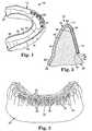
- Fig. 1 is a perspective view of an exemplary medication delivery tray constructed in accordance with certain embodiments of the present invention;
- Fig. 2 is a perspective view of an exemplary model of a patient's dental arch as may be useful in making the tray shown in Fig. 1;
- Fig. 3 is an enlarged side sectional view of the model illustrated in Fig. 2 along with a sheet of plastic material that has been formed over the model to make the tray of Fig. 1;
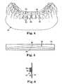
- Fig. 4 is a perspective view of an exemplary model of a patient's dental structure along with an applique for making a medication delivery tray according to alternative embodiments of the invention;
- Fig. 5 is a side elevational view of the applique alone that is shown in Fig. 4 as it appears before placement on the model, wherein the applique is carried on a release liner; and
- Fig. 6 is an end cross-sectional view (not to scale) of the applique and release liner shown in Fig. 5.
- A custom-made medication delivery tray for delivering medication to tooth structure of a dental patient according to one embodiment of the invention is illustrated in Fig. 1 and is broadly designated by the
numeral 10. The tray includes abody 12 having a base 14, a buccolabial wall 16 (i.e., a wall next to the patient's lips or cheeks) and a lingual wall 18 (i.e., a wall next to the patient's tongue). Thebase 14 and thewalls elongated channel 20. - The
channel 20 has an overall, generally "U"-shaped configuration in reference planes perpendicular to the longitudinal axis of thechannel 20. Moreover, thebody 12 as well as thechannel 20 have an overall, generally "U"-shaped configuration in plan view or when considered in a reference plane containing the longitudinal axis of thechannel 20. Preferably, thebody 12 extends a distance equivalent to the entire length of the patient's arch or at least a substantial majority of the length of the patient's dental arch, although other constructions are also possible. For example, thetray 10 and thechannel 20 may extend along only the patient's anterior teeth, or only along one quadrant of one dental arch. - Preferably, the
channel 20 is generally complemental in configuration to the patient's dental arch so that unnecessary void spaces between the tray and the patient's oral structures are avoided and the resulting tray is not considered obtrusive when worn in the mouth. As an option, however, small recesses orwells 21 may be made along the inner surface of thebuccolabial wall 16 adjacent the facial surface of each tooth in order to provide a pocket for receiving a quantity of the medication. Optionally, thewells 21 are provided only along the patient's anterior, cuspid and bicuspid teeth as may be useful, for example, when thetray 10 is used for delivering a bleaching composition to the most visible teeth. However, if the patient's molar teeth are also heavily stained, it may be desirable to provide such wells in areas of thebuccolabial wall 16 adjacent such molar teeth as well. - The
lingual wall 18 includes aperipheral edge section 22. Theedge section 22 has anouter edge 24 that extends along a line that is spaced at least in part and preferably spaced along substantially its entire length at least 4 mm. in a gingival direction from the gingival margin of the lingual side of the patient's dental arch receiving thetray 10. More preferably, theouter edge 24 extends along a line that is spaced at least in part (and more preferably is spaced substantially along its entire length) a distance of 6 mm. in a gingival direction from the gingival margin of the patient's dental arch along its lingual side. Optionally, theedge 24 is spaced no greater than 20 mm. and more preferably less than 12 mm. in a gingival direction at any point from the gingival margin of the lingual side of the dental arch. - The preferred spacing of the
edge 24 from the gingival margin along the lingual side of the dental arch as mentioned in the previous paragraph is provided at least in regions adjacent the patient's anterior teeth (i.e., in regions adjacent the patient's central and lateral incisors). Optionally, theedge 24 approaches the gingival margin and theedge section 22 narrows in width as either end of thechannel 20 is approached. For example, theedge 24 may be as close as 2 mm., or optionally directly adjacent the patient's gingival margin in regions next to the patient's molar teeth. - As another option, the
tray 10 when made to fit the upper arch includes palatal section that extends across a majority of the patient's palate and is integrally connected to thelingual wall 18. In that instance the outer edge is spaced a distance greater than 12 mm. from the gingival margin at least in regions next to the anterior teeth. - The
buccolabial wall 16 has anouter edge 26 that extends along the gingival margin of the patient's dental arch on a buccolabial side of the teeth. Preferably, theouter edge 26 is located up to 2.0 mm, and more preferably only up to 1.0 mm, in an occlusal direction from the gingival margin and does not contact the gingival margin of the patient's dental arch when the tray is in use in the oral cavity. Preferably, theedge 26 has a scalloped configuration that precisely matches the contoured shape of the adjacent gingival margin. Alternatively, however, theedge 26 could extend along the gingival margin in a generally straight path and pass across the location of each tooth where the gingival margin reaches an apex in a gingival direction (i.e., the location of each tooth, typically near the center of each tooth, where the exposed enamel extends the greatest distance in a gingival direction; in this alternative, thebuccolabial wall 16 completely covers each gingival papilla that extends in an occlusal direction toward an interproximal region between adjacent teeth. The location of theouter edge 26 as described above helps ensure that thetray 10 does not irritate the soft gingival tissue of the buccolabial side of the arch. Gingival irritation from abrasion from the tray in this region when combined with the presence of certain medications (such as bleaching compositions) might otherwise result in the formation of highly unpleasant sores. - A custom or custom-made dental tray refers to a dental tray that is made using a mold, casting or other model of the patient's dental structures. Custom dental tray also refers to a dental tray that is made using digital data representative of the patient's dental structure as described in further detail below. Dental structures and oral structures refer to the teeth and/or gingiva.
- Fig. 2 is a perspective view of an example of a casting or
model 30 that is a replica of one dental arch of the patient's dental structure. One method of making themodel 30 involves first taking an impression of the patient's dental structure using an alginate impression material or other suitable impression material. Themodel 30 may be a replica of either the patient's upper or lower dental arch. - In the example of the
model 30 as shown in Fig. 2, themodel 30 includes a number ofmodel teeth 32 representing the teeth of the patient's selected dental arch. In addition, themodel 30 includes modelgingival tissue 34 that is a replica of the patient's gingival tissue of the selected dental arch. In Fig. 2, a model gingival margin is designated by the numeral 36 and generally has the appearance of a scalloped line extending along the model arch and along a path that follows the line of differentiation between the replica enamel of eachmodel tooth 32 and the adjacent modelgingival tissue 34. - A preferred method of making the
tray 10 includes providing a sheet member that is made of a thermoplastic material such as polypropylene, ethylene or vinyl acetate, such as ethylene vinyl acetate (EVA). Suitable EVA materials include, for example, 0.04 in. (1.0 mm.) thick EVA vacuum forming material (Catalog No. 089-5003, from Patterson Dental Supply, Inc.). EVA is commercially available and approved for oral use by the U.S. Food and Drug Administration. These materials are easily thermoformed or vacuumed formed over themodel 30 using conventional techniques. Preferably, the sheet member has a thickness no greater than .080 in (2.0 mm) and is translucent. - Once the sheet member has been formed over the
model 30, the sheet member is trimmed according to the principles of the present invention. Fig. 3 is a sectional illustration of anexemplary sheet member 40 that has been formed over one of themodel teeth 32 and a portion of the modelgingival tissue 34. As shown, thesheet member 40 has assumed a configuration closely complemental to underlying areas of themodel tooth 32 and the modelgingival tissue 34. - The
sheet member 40 is trimmed so that the resultingtray 10 has abuccolabial wall 16 andlingual wall 18 as described above. Thesheet member 40 may be trimmed with a scissors, a knife or any other suitable tool as desired. Optionally, a pencil or ink marking may be made on thesheet member 40 while thetray 10 is on themodel 30 to serve as a guide for trimming once thetray 10 has been removed from themodel 30. As another option, a knife is used to trim thetray 10 while thetray 10 is still in place on themodel 30. The placement of such guide lines is facilitated when thesheet member 40 is made of a transparent or translucent material having sufficient light transmittance to allow the practitioner to see the model gingival margin through thesheet member 40 while thesheet 10 is received on themodel 30. - It has been found that the
lingual edge section 22 is a significant advantage, in that theedge section 22 provides an effective seal that helps to reduce the flow of saliva into thechannel 20. When thetray 10 is in use, the patient's tongue may bear against thelingual wall 18, and in some instances may bear against thelingual wall 18 at repeated, spaced apart intervals of time. Such pressure on thelingual wall 18 tends to establish a "pumping" action that causes movement of water, saliva and/or medication. - The pumping action caused by the tongue creates a hydrodynamic force that tends to move the water, saliva and/or medication in the
tray 10 in various directions. One direction of movement is in a direction from thelingual wall 18 to thebuccolabial wall 16 over the occlusal tips of the teeth, and toward the gingival edge of thebuccolabial wall 16. Thelingual edge section 22 provides a flap of material that functions as a seal to resist and hinder such flow. - Additionally, many patients have a tendency to fidget with dental trays when the tray is in use. For example, many patients, whether consciously or unconsciously, use their tongue to "play". with the gingival edge of the tray along its lingual side. Disturbing of the outer edge in such fashion is a disadvantage, in that the tongue may unintentionally lift the outer edge on the lingual side and enable the medication to escape. Lifting of the gingival edge may also enable additional saliva or water to enter the tray channel, thus diluting the medication in the tray and/or enhancing the hydrodynamic "pumping" action the next time that the tongue is pressed against the lingual wall of the tray.
- The
lingual edge 24 of the present invention is a significant advantage in that it is spaced a significant distance from the gingival margin of the lingual side of the patient's dental arch. That spacing hinders the patient's tongue from lifting thelingual edge section 22 and many of the problems described above are consequently avoided. As a result, medication in thechannel 20 remains in place for a greater length of time than would otherwise be possible and more effectively treats the dental structure of interest. - The present invention is also beneficial because the
tray 10 can be made from a relatively thin sheet member, resulting in a tray that is less obtrusive in the mouth. In the past, dental trays were often made of a material having a thickness ranging from about 0.08 in. (2 mm.) to about 0.15 in. (3.8 mm.) since such materials tend to be better at resisting hydrodynamic forces than dental trays made from thinner materials. However, because thelingual edge section 22 of the present invention provides an effective seal that reduces the flow of medication, saliva and/or water thechannel 20, thetray 10 can be made from a relatively thin sheet member (such as 0.04 in., or 1 mm. as described above). Moreover, use of a relatively thin sheet member increases the flexibility of thelingual edge section 22 so that theedge section 22 readily shifts as needed to closely contact the underlying tissue and quickly establish a good seal against adjacent soft tissue. - Optionally, each of the
wells 21 that is located along thebuccolabial wall 16 of thetray 10 contain a plurality of support members 42 (shown in Fig. 1 but not to scale) that extend in a lingual direction to engage the patient's dental structure. Thesesupport members 42 are preferably discreet and free standing and resist compression of the reservoirs as might otherwise occur due to hydrodynamic forces and/or movement of thetray 10 in the patient's oral cavity. - One method of making the
support members 42 involves the use ofappliques 44 such as are shown in Fig. 2. In this method, anapplique 44 is applied to buccolabial surfaces of themodel teeth 32. The overall shape of theapplique 44 is selected to match to the desired, overall shape of the corresponding well 21. A suitable adhesive is used to affix theappliques 44 to the selectedmodel teeth 32. - Each
applique 44 includes a series ofprotrusions 46 that project outward from abacking 48 as illustrated in Fig. 3. In this embodiment, theprotrusions 46 serve as a mold for molding thesupport members 42 in thesheet member 40. The appliques preferably remain on themodel 30 as the moldedtray 10 is detached from themodel 30 so that further handling ofindividual appliques 44 is avoided. Once thetray 10 is detached from themodel 30 and theappliques 44, thewells 21 with thesupport members 42 are exposed and present a configuration that represents the inverse of the shape of theappliques 44. - The
protrusions 46 and/or the resultingsupport members 42 can have a variety of geometric shapes in cross section, such as rectangular, circular, semi-circular, triangular, square, hexagonal, and the like. Thesupport members 42 may assume a variety of shapes, such as cones, truncated cones, rods, pyramids, truncated pyramids, cubes, gum drops, cylinders, nail heads or mushroom-shaped members, and the like. The outer ends of thesupport members 42 may be flat, rounded, pointed or a variety of other shapes, as determined by the shape of the spaces between theprotrusions 46 and the optional land areas between theprotrusions 46. Theappliques 44 may have a micro-replicated surface that is accomplished by using a variety of methods, such as disclosed in U.S. Patent Nos. 5,152,917 (Pieper, et al.) and 5,500,273 (Holmes et al.). - The
protrusions 46 may be discrete and spaced apart from each other. Alternatively, theprotrusions 46 may be integrally interconnected to form one or more networks of protruding structure. For example, theprotrusions 46 may present an ordered or random configuration. An example of an ordered configuration includes a honeycomb pattern where optionally one or more honeycombs may be separated or decoupled from adjacent honeycombs. Other examples of an ordered configuration include oral structures and elongated rails. - Optionally, if the
projections 46 are thesupport members 42, the projections 46 (such as, for example, the oval or honeycomb structures) may have a small medication-receiving recess or cavity at their outer ends that presents the oval or honeycomb (i.e., hexagonal) appearance. Preferably, theprotrusions 46 have sufficient stiffness or rigidity so that the recess or cavity does not collapse under the forces present in the oral cavity during use. In this manner, the medication tends to remain in the cavities for a longer period of time. - As an alternative, the
appliques 44 may be embedded and integrally molded with thesheet member 40 during molding of thesheet member 40. In this alternative, appliques 44 are reversed from their orientation shown in Fig. 3 so that theprotrusions 46 serve as thesupport members 42. Optionally, a section of double-sided adhesive tape extends across outer ends of theprotrusions 46 in this embodiment to temporarily retain theappliques 44 on themodel 30 during molding of thesheet member 40. - Fig. 4 is an illustration of an
applique 50 that is provided on amodel 52 according to other embodiments of the invention. Themodel 52 is identical to themodel 30, and includes a series ofmodel teeth 54 as well asgingival tissue 56. - The
applique 50 has an elongated strip configuration to engage with portions of themodel 52 corresponding to portions of multiple teeth. In the embodiment shown in Fig. 4, theapplique 50 extends from one second bicuspid tooth to the other. However, if the patient's molar teeth are heavily stained, it may be desirable to provide a somewhat longer applique in order to extend over the molar tooth surfaces as well. - As shown in more detail in Figs. 5 and 6, the
applique 50 includes abacking layer 58 and a number ofprotrusions 60 connected to thebacking layer 58. Theprotrusions 60 provide the discreet, freestanding support members described above. Preferably, the protrusions 60 (as well as thesupport members 42 in Fig. 1) are arranged to define tortuous paths. A tortuous path refers to a passageway or conduit that is not substantially straight and extends past the sides of a plurality of protrusions 60 (or support members) in the spaces between adjacent protrusions 60 (or support members). The tortuous paths are preferably arranged to increase flow resistance in a gingival direction through the resulting reservoir and/or in a mesial-distal direction along the length of the tray channel. To the extent that any segment of the tortuous paths is straight, that segment is preferably skewed with respect to the gingival direction or the mesial-distal direction of the channel. Optionally, the protrusions or support members are constructed of a hydrophilic material. - In general, the number of protrusions 60 (or support members 42) per unit area is preferably in the range of about 78 per square cm. (500 per sq. in.) to about 465 per sq. cm. (3000 per sq. in.). An example of a suitable number is about 144 per sq. cm. (900 per sq. in.). However, a higher or lower number of
protrusions 60 orsupport members 42 per unit area may be optimal in certain circumstances and the optimal number may depend on factors such as the nature of the sheet member material forming the tray, the characteristics of the medication and the height, shape and diameter of theprotrusions 60. The height of theprotrusions 60 orsupport members 42 is preferably in the range of about 0.5 mm. to about 1.5 mm., although longer orshorter protrusions 60 orsupport members 42 may be used for specific applications, depending upon the viscosity of the medication, the nature of the treatment, the specific dental structure being treated, etc. - The
protrusions 60 that are illustrated in Fig. 6 each include a stem that projects outwardly from thebacking layer 58 as well as an enlarged head. Various manufacturing processes for forming an array of upstanding headed stems integral with a backing layer are described in U.S. Patent No. 4,290,174 (Kalleberg) U.S. Patent No. 4,984,339 (Provost et al.), WO 94/23610 (Miller et al.), WO 98/30381 (Miller et al.) and PCT/US97/15960 (Kempfer). - Optionally, the
protrusions 60 are made by a micro-replication process. An example of a suitable applique is a die-cut section of the hook side of a polypropylene micro-replicated mechanical fastener such as no. CS-200 diaper tape from 3M Company. Optionally, theprotrusions 60 may be identical or similar to theprotrusions 46 mentioned above. - An
adhesive tape 62 is releasably connected to the enlarged heads of theprotrusions 60. An example of a suitable adhesive tape is a medical grade double-sided adhesive tape such as no. 1522 from 3M Company. As an alternative, a layer of adhesive may be provided in place of theadhesive tape 62. - The
adhesive tape 62 is also initially connected to arelease liner 64 to facilitate handling of theapplique 50 before theapplique 50 is applied to themodel 52. Suitable materials for therelease liner 64 include a section of poly(ethylene terephthalate) ("PET") sheeting that is coated with silicone to enhance release of the adhesive. - In use, the
applique 50 and theadhesive tape 62 are detached from therelease liner 64 and trimmed as necessary. Theapplique 50 and theadhesive tape 62 may be trimmed after being initially placed on themodel 50 or alternatively trimmed before detachment from therelease liner 64. Theapplique 50 is trimmed to a length sufficient to extend across all of the tooth surfaces intended to receive medication. - Preferably, a gingival edge of the
applique 50 includes anotch 66 that is located in the center of theapplique 50 along its length. When theapplique 50 is placed on themodel 52, the practitioner places thenotch 66 along the midline (i.e., in the center of the dental arch of the model 52), so that theapplique 50 is properly centered on themodel 52. Thenotch 66 provides a visual alignment guide to facilitate placement of theapplique 50 on themodel 50. Preferably, theapplique 50 is aligned to the mid-third of themodel teeth 54 in an occlusal-gingival direction as shown in Fig. 4. - Preferably, but not necessarily, the
applique 50 is initially curved in a wide arc when attached to therelease liner 64 as can be observed by reference to Figure 5. The arc-shaped configuration of theapplique 50 facilitates conforming theapplique 50 to the buccolabial tooth surfaces of themodel 52 as theapplique 50 is attached to themodel 52. Optionally, the practitioner may apply finger pressure to theapplique 50 in areas extending over interproximal regions of the dental arch in order to better conform theapplique 50 to the curvature of theindividual model teeth 54. - Next, a dental medication delivery tray is formed over the
model 52 and theapplique 50. For example, a sheet member of thermoplastic material may be thermoformed or vacuum formed over themodel 52 and theapplique 50. Suitable thermoplastic materials include, for example, the EVA materials described above. Preferably, theapplique 50 both chemically and mechanically bonds to the thermoplastic material in order to remain non-removably affixed in place in the tray. - The resultant dental tray is then removed from the
model 52. Preferably, theadhesive tape 62 preferentially adheres to themodel 52, so that as the tray is pulled from themodel 50 theadhesive tape 62 detaches from theapplique 50 and remains on themodel 52. The tray is trimmed as described above in connection with thetray 10. In use, medication such as a dental bleaching agent is applied to theapplique 50 in the tray and the tray is then placed over the patient's dental arch. - Use of the
applique 50 is a significant advantage over conventional tray fabrication techniques, in that theapplique 50 can be applied to a plurality ofmodel teeth 54 at once and preferably to all of themodel teeth 54 that correspond to the patient's teeth to be treated. As a result, application of a reservoir-making material to the surface of eachmodel tooth 54 on an individual basis can be avoided and the total time required to make the tray is substantially reduced. The tray is preferably made with theapplique 50 permanently bonded to the thermoplastic material, although as an alternative theapplique 50 may be placed over themodel teeth 54 with itsprotrusions 60 facing outwardly (i.e. buccolabially) such that an impression of theapplique 50 is formed in the thermoplastic material to create the reservoir and support structures. - As illustrated in Figures 4 and 5, the
applique 50 has a generally rectangular, strip-like configuration, although other configurations are also possible. For example, the applique may have a substantially straight upper edge to match the occlusal edges of theteeth 54, and a scalloped lower edge to match the shape of the gingival margin. In practice, however, satisfactory results have been obtained with the generally rectangular shape shown in Figures 4 and 5. Since the medication in the tray slowly escapes from the reservoir created by theapplique 50 and contacts adjacent tooth structure while the tray is in use, substantially all of the buccolabial surfaces of the teeth underlying theapplique 50 are subjected to the medication. For example, if the medication is a dental bleaching agent, the escape of the bleaching agent from the reservoir ensures that the entire buccolabial surface of each tooth is uniformly bleached to generally the same color, even though the reservoir does not extend over gingival portions of the buccolabial tooth surfaces. - Alternatively, medication delivery trays according to the invention may also be made using appliques of other shapes or sizes, using appliques made of other materials or using appliques in different methods for making the tray. Such alternative appliques and methods are described in applicant's pending U.S. Patent Application Serial No.09/217765 entitled "MEDICATION DELIVERY TRAY".
- Moreover, any of the techniques described above for making a dental tray may include as an option the use of a dental model that is made using digital data instead of a dental model that is cast from a dental impression. For example, a model arch similar to the
model - Other means for generating digital information of the patient's dental arch may also be employed. For example, the digital information may be generated electromechanically (e.g., by stylus scanning), by laser scanning, by photogammetry, by sonic ranging, by digital video scanning or magnetically. Examples of devices for generating the information are described in an article by Rekow entitled"Computer Aided Design and Manufacture in Dentistry: A Review of the State of the Art", from the Journal of Prosthetic Dentistry, Vol. 58, page 512 (1987). Other examples are described in U.S. Patent Nos. 5,078,599, 5,131,844, 5,338,198, 4,611,288 and 5,372,502 as well as in an article entitled"Three-dimensional dental cast analyzing system with laser scanning" (Kuroda, et al., Am. J. Ortho. Dent. Othrop., Vol. 110 [4], October 1996, pages 365-69).
- The medication delivery tray in accordance with the present invention is particularly suited for patients who desire to bleach their teeth. A common dental bleaching agent contains about 10% to about 16% carbamide peroxide, also called urea hydrogen peroxide, urea peroxide, hydrogen peroxide carbamide and perhydrol-urea. Carbamide peroxide has been used by dental clinicians since the 1960's as an oral antiseptic. Tooth whitening was a side effect of extended contact time. Over the counter ("OTC") compositions of 10% carbamide peroxide are available as "Gly-Oxide" by Marion Laboratories and "Proxigel" by Reed and Carnrick. A preferred dental bleaching agent comprises 64.86% propylene glycol, 21.00% glycerol, 1.5% carboxypolymethylene (e.g. Carbopol brand No. 980), 2.34% tris(hydroxymethyl)aminomethane, 0.30% mint flavor and 10.00% carbamide peroxide, with the viscosity increased by adjusting the pH to about 5.8.
- A number of possible modifications and additions will become apparent to those skilled in the art after reviewing the description above. Accordingly, the invention should not be deemed limited to the specific, currently preferred embodiments that are described in detail above, but instead only by the scope of the claims that follow.
Claims (17)
- An assembly comprising:a dental arch model (30,52) having model tooth structure (32,54) and model gingiva (34,56); and a custom-made medication delivery tray (10) for delivering medication to tooth structure of a dental patient comprising:a body (12) having a base (14), a buccolabial wall (16) and a lingual wall (18), wherein the base (14), the buccolabial wall (16) and the lingual wall (18) present a channel (20) generally complemental in configuration to the tooth structure (32,54),characterized in that the buccolabial wall (16) extends at least in part along the gingival margin (36) of the buccolabial side of the tooth structure (32,54) without contacting the gingiva and the lingual wall (18) extends along a line that is spaced at least in part at least 4 mm. in a gingival direction from the gingival margin (36) of the tooth structure (32,54) on a lingual side of the tooth structure (32,54).
- An assembly according to claim 1 wherein the lingual wall (18) extends along a line that is spaced at least in part at least 6 mm. in a gingival direction from the gingival margin (36) from the tooth structure (32,54) on a lingual side of the tooth structure (32,54).
- An assembly according to claim 1 wherein the lingual wall (18) extends along a line that is spaced no greater than 20 mm. in a gingival direction from the gingival margin (36) of the tooth structure (32,54) on a lingual side of the tooth structure (32,54).
- An assembly according to claim 1 wherein the lingual wall (18) extends along a line that is spaced no greater than 12 mm. in a gingival direction from the gingival margin (36) of the tooth structure (32,54) on a lingual side of the tooth structure (32,54).
- An assembly according to claim 1 wherein the lingual wall (18) includes an outer edge that extends along a line that decreases in spacing from the gingival margin (36) of the tooth structure (32,54) on a lingual side of the tooth structure (32,54) as distal ends of the channel (20) are approached.
- An assembly according to claim 1 wherein the body (12) is made from a sheet member (40) having a thickness of about 1 mm or less.
- An assembly according to claim 1 wherein the lingual wall (18) includes at least one medication reservoir.
- A method of making a medication delivery tray for delivering medication to dental structure of a patient comprising the acts of:providing a model of at least a portion of a dental arch;forming a sheet member over at least part of the model; andtrimming the sheet member to make the tray, wherein the act of trimming the sheet member includes the act of trimming the sheet member along a path corresponding to a line spaced no greater than 1.0 mm in an occlusal direction from a the gingival margin of the model on a buccolabial side of the model and also includes the act of trimming the sheet member along a path corresponding to a line that is spaced at least in part at least 4 mm. in a gingival direction from the gingival margin of the model on a lingual side of the model.
- A method of making a medication delivery tray according to claim 8 wherein the act of trimming the sheet member includes the act of trimming the sheet member along a line that is spaced at least in part at least 6 mm. in a gingival direction from the gingival margin of the model on a lingual side of the model.
- A method of making a medication delivery tray according to claim 8 wherein the act of trimming the sheet member includes the act of trimming the sheet member along a line that is spaced no greater than 20 mm. in a gingival direction from the gingival margin of the model on a lingual side of the model.
- A method of making a medication delivery tray according to claim 8 wherein the act of trimming the sheet member includes the act of trimming the sheet member along a line that is spaced no greater than 12 mm. in a gingival direction from the gingival margin of the model on a lingual side of the model.
- A method of making a medication delivery tray according to claim 8 wherein the act of trimming the sheet member includes the act of trimming the sheet member along a line that is spaced a decreasing dimension in a gingival direction from the gingival margin of the model on a lingual side of the model as at least one distal end of the tray is approached.
- A method of making a medication delivery tray according to claim 8 wherein the act of forming a sheet member over at least part of the model includes the act of providing a sheet member having a thickness of about 1 mm or less.
- A method of making a medication delivery tray according to claim 8 wherein the act of forming a sheet member over at least part of the model includes the act of making at least one medication reservoir in a lingual wall of the tray.
- A method of making a medication delivery tray according to claim 8 wherein the act of trimming the sheet member is carried out after the sheet member has been detached from the model.
- A method of making a medication delivery tray according to claim 8 wherein the act of trimming the sheet member is carried out while the sheet member is connected to the model.
- A method of making a medication delivering tray according to claim 8 wherein the act of trimming the sheet member includes the act of trimming the sheet member as necessary to provide a palatal region.
Applications Claiming Priority (5)
| Application Number | Priority Date | Filing Date | Title |
|---|---|---|---|
| US333376 | 1989-04-05 | ||
| US24082399A | 1999-02-01 | 1999-02-01 | |
| US240823 | 1999-02-01 | ||
| US09/333,376US6142780A (en) | 1999-02-01 | 1999-06-15 | Custom tray for delivering medication to oral structures |
| PCT/US1999/030912WO2000044303A1 (en) | 1999-02-01 | 1999-12-22 | Custom tray for delivering medication to oral structures |
Publications (2)
| Publication Number | Publication Date |
|---|---|
| EP1148836A1 EP1148836A1 (en) | 2001-10-31 |
| EP1148836B1true EP1148836B1 (en) | 2007-05-02 |
Family
ID=26933754
Family Applications (1)
| Application Number | Title | Priority Date | Filing Date |
|---|---|---|---|
| EP99967627AExpired - LifetimeEP1148836B1 (en) | 1999-02-01 | 1999-12-22 | Custom tray for delivering medication to oral structures |
Country Status (6)
| Country | Link |
|---|---|
| US (1) | US6142780A (en) |
| EP (1) | EP1148836B1 (en) |
| JP (1) | JP2002535073A (en) |
| BR (1) | BR9917016A (en) |
| DE (1) | DE69936002T2 (en) |
| WO (1) | WO2000044303A1 (en) |
Families Citing this family (67)
| Publication number | Priority date | Publication date | Assignee | Title |
|---|---|---|---|---|
| US6582708B1 (en) | 2000-06-28 | 2003-06-24 | The Procter & Gamble Company | Tooth whitening substance |
| US7878801B2 (en)* | 2000-09-21 | 2011-02-01 | Align Technology, Inc. | Systems and methods for dental appliance compliance indication |
| US6607382B1 (en)* | 2000-09-21 | 2003-08-19 | Align Technology, Inc. | Methods and systems for concurrent tooth repositioning and substance delivery |
| US6945778B2 (en)* | 2002-08-20 | 2005-09-20 | Ultradent Products, Inc. | Customized dental trays comprising ultra low density polyethylene and methods for making and using such trays |
| US6969255B2 (en)* | 2002-08-20 | 2005-11-29 | Archtek, Inc. | Preformed tray comprising ultra low density polyethylene |
| US6848905B2 (en) | 2002-08-20 | 2005-02-01 | Archtek, Inc. | Method of making a dental tray using a patient's teeth as a template |
| US8524200B2 (en) | 2002-09-11 | 2013-09-03 | The Procter & Gamble Company | Tooth whitening products |
| US7645137B2 (en)* | 2002-12-04 | 2010-01-12 | Bryan Wasyluch | Method and apparatus for bleaching teeth |
| US7004756B2 (en)* | 2003-01-24 | 2006-02-28 | Ultradent Products, Inc. | Pre-shaped dental trays and treatment devices and methods that utilize such dental trays |
| US6964571B2 (en) | 2003-01-24 | 2005-11-15 | Ultradent Products, Inc. | Pre-shaped dental trays and treatment devices and methods that utilize such dental trays |
| US20040154626A1 (en)* | 2003-02-12 | 2004-08-12 | E-Z Gard Industries, Inc. | Mouthguard |
| US20040214140A1 (en)* | 2003-04-25 | 2004-10-28 | Ultradent Products, Inc. | Anatomical preformed tray incorporating a severable handle |
| US7020963B2 (en)* | 2003-05-02 | 2006-04-04 | 3M Innovative Properties Company | Method and apparatus for indirect bonding of orthodontic appliances |
| US7188421B2 (en)* | 2003-05-02 | 2007-03-13 | 3M Innovative Properties Company | Orthodontic appliances having a contoured bonding surface |
| US6860736B2 (en)* | 2003-05-23 | 2005-03-01 | Ultradent Products, Inc. | Oral treatment devices that include a thin, flexible barrier layer and an endoskeleton treatment or adhesive composition |
| US7056118B2 (en) | 2003-05-27 | 2006-06-06 | Ultradent Products, Inc. | Compositions and devices having a tray-like configuration for delivering a medicament and methods of manufacturing and using such compositions and devices |
| US7011523B2 (en)* | 2003-10-22 | 2006-03-14 | Ultradent Products, Inc. | Bleaching compositions and devices having a solid adhesive layer and bleaching gel adjacent thereto |
| US7074042B2 (en)* | 2003-05-27 | 2006-07-11 | Ultradent Products, Inc. | Tray-like dental bleaching devices having a barrier layer and a substantially solid bleaching composition |
| US7059857B2 (en)* | 2003-05-27 | 2006-06-13 | Ultradent Products, Inc. | Substantially solid desensitizing compositions and devices having a tray-like configuration and methods of manufacturing and using such compositions and devices |
| US7040897B2 (en) | 2003-05-23 | 2006-05-09 | Ultradent Products, Inc. | Thin, flexible membrane dental trays and systems and methods utilizing such trays |
| US7052275B2 (en)* | 2003-05-27 | 2006-05-30 | Ultradent Products, Inc. | Kits and methods for bleaching and desensitizing teeth |
| US7048543B2 (en)* | 2003-05-27 | 2006-05-23 | Ultradent Products, Inc. | Substantially solid bleaching composition in a tray-like configuration |
| US6997708B2 (en)* | 2003-10-22 | 2006-02-14 | Ultradent Products, Inc. | Treatment compositions and strips having a solid adhesive layer and treatment gel adjacent thereto |
| US6981874B2 (en)* | 2003-10-22 | 2006-01-03 | Ultradent Products, Inc. | Dental bleaching compositions and devices having a solid activation adhesive layer or region and bleaching gel layer or region |
| US20050074717A1 (en)* | 2003-10-03 | 2005-04-07 | 3M Innovative Properties Company | Method and apparatus for bonding orthodontic appliances to teeth |
| US7137812B2 (en)* | 2003-10-03 | 2006-11-21 | 3M Innovative Properties Company | Apparatus for indirect bonding of orthodontic appliances and method of making the same |
| US7192280B2 (en)* | 2004-02-19 | 2007-03-20 | Ultradent Products, Inc. | Dental bleaching devices having a protective adhesive region |
| US7059858B2 (en) | 2004-02-19 | 2006-06-13 | Ultradent Products, Inc. | Universal tray design having anatomical features to enhance fit |
| US7264471B2 (en) | 2004-05-05 | 2007-09-04 | Ultradent Products, Inc. | Methods and kits for bleaching teeth while protecting adjacent gingival tissue |
| US7625210B2 (en)* | 2004-08-09 | 2009-12-01 | Ultradent Products, Inc. | Treatment devices for providing oral treatments and kits and methods that utilize such treatment devices |
| JP4897489B2 (en)* | 2004-09-16 | 2012-03-14 | 昭和薬品化工株式会社 | Mouthpiece for heel stretching |
| US8899976B2 (en) | 2004-09-24 | 2014-12-02 | Align Technology, Inc. | Release agent receptacle |
| US7168950B2 (en)* | 2004-10-18 | 2007-01-30 | 3M Innovative Properties Company | Orthodontic methods and apparatus for applying a composition to a patient's teeth |
| US20060115785A1 (en) | 2004-11-30 | 2006-06-01 | Chunhua Li | Systems and methods for intra-oral drug delivery |
| US20060141416A1 (en)* | 2004-12-24 | 2006-06-29 | Knutson Eric J | Occlusal indicator tray & processes therefor |
| US7452209B2 (en) | 2005-05-02 | 2008-11-18 | Ultradent Products, Inc. | Exoskeleton support for placement of a dental treatment strip |
| US20060275369A1 (en)* | 2005-06-01 | 2006-12-07 | Cao Group, Inc. | Orally Therapeutic Plastics and Devices Formed Therefrom |
| US7704074B2 (en)* | 2005-08-25 | 2010-04-27 | Cao Group, Inc | Two piece dental anatomical form and holder |
| US8021146B2 (en)* | 2006-06-07 | 2011-09-20 | 3M Innovative Properties Company | Apparatus and methods for controlling moisture during orthodontic indirect bonding procedures |
| US7364428B2 (en)* | 2006-06-07 | 2008-04-29 | 3M Innovative Properties Company | Orthodontic indirect bonding tray with moisture control |
| US8007277B2 (en) | 2006-08-25 | 2011-08-30 | Ultradent Products, Inc. | Non-custom dental treatment trays and mouth guards having improved anatomical features |
| FR2905258A1 (en)* | 2006-09-01 | 2008-03-07 | Thierry Slama | Intra-oral device for e.g. cleaning teeth and gingiva, has channel to inlet and outlet, where inlet and outlet are located at zones such that fluid is supplied from exterior of mouth to zone of dental arch for acting on teething/gingiva |
| WO2008086566A1 (en)* | 2007-01-15 | 2008-07-24 | Oral Health Australia Pty Ltd | Bioactive delivery device |
| US8202091B2 (en) | 2007-08-31 | 2012-06-19 | Ultradent Products, Inc. | Dental treatment trays comprising silicone elastomeric material |
| US20100028829A1 (en) | 2008-07-31 | 2010-02-04 | Ultradent Products, Inc. | Chemically activated dental bleaching trays |
| US8172569B2 (en) | 2008-06-12 | 2012-05-08 | Align Technology, Inc. | Dental appliance |
| CA2740445C (en) | 2010-05-17 | 2018-11-20 | Louis F. Polk, Iii | Mouthguard with linear storage configuration |
| USD663486S1 (en) | 2010-06-02 | 2012-07-10 | Shock Doctor, Inc. | Custom mouthguard |
| CA2742037C (en) | 2010-06-02 | 2013-09-10 | Shock Doctor, Inc. | Custom mouthguard |
| USD663485S1 (en) | 2010-06-02 | 2012-07-10 | Shock Doctor, Inc. | Custom mouthguard |
| USD688832S1 (en) | 2011-05-17 | 2013-08-27 | Shock Doctor, Inc. | Mouthguard |
| ES2380252B2 (en)* | 2012-03-16 | 2012-09-17 | Universidade De Santiago De Compostela | INTRAORAL DEVICE OF SUPERPOSED SPLINES (DIFES) FOR COLLECTION OF SAMPLES OF THE DENTAL PLATE. |
| US10285915B2 (en) | 2012-10-17 | 2019-05-14 | The Procter & Gamble Company | Strip for the delivery of an oral care active and methods for applying oral care actives |
| US9610141B2 (en) | 2014-09-19 | 2017-04-04 | Align Technology, Inc. | Arch expanding appliance |
| US10449016B2 (en)* | 2014-09-19 | 2019-10-22 | Align Technology, Inc. | Arch adjustment appliance |
| WO2016116813A1 (en)* | 2015-01-22 | 2016-07-28 | Americo Fernandes | Dental appliances |
| US10201409B2 (en) | 2015-07-07 | 2019-02-12 | Align Technology, Inc. | Dental appliance having ornamental design |
| AU2017366755B2 (en) | 2016-12-02 | 2022-07-28 | Align Technology, Inc. | Methods and apparatuses for customizing rapid palatal expanders using digital models |
| US11026831B2 (en) | 2016-12-02 | 2021-06-08 | Align Technology, Inc. | Dental appliance features for speech enhancement |
| EP3547952B1 (en) | 2016-12-02 | 2020-11-04 | Align Technology, Inc. | Palatal expander |
| US12274597B2 (en) | 2017-08-11 | 2025-04-15 | Align Technology, Inc. | Dental attachment template tray systems |
| EP3773320B1 (en) | 2018-04-11 | 2024-05-15 | Align Technology, Inc. | Releasable palatal expanders |
| EP4093321B1 (en) | 2020-01-23 | 2024-03-13 | 3Shape A/S | System and method for fabricating a dental tray |
| CN112998636B (en)* | 2021-02-05 | 2022-02-22 | 山东大学 | Tongue lifting opening device for oral and maxillofacial surgery |
| IT202100015023A1 (en)* | 2021-06-09 | 2022-12-09 | Airnivol S P A | DENTAL APPLIANCE SUITABLE FOR FITTING ON A DENTAL ARCH AND RELATED SYSTEMS AND METHODS |
| JP1724516S (en)* | 2021-12-31 | 2022-09-12 | shell dental instrument | |
| US12303345B1 (en) | 2024-02-22 | 2025-05-20 | Sean S. Lee | Dental treatment tray |
Family Cites Families (54)
| Publication number | Priority date | Publication date | Assignee | Title |
|---|---|---|---|---|
| US34196A (en)* | 1862-01-21 | Improvement in iron cutters or sleighs | ||
| US1934688A (en)* | 1931-02-24 | 1933-11-14 | Ackerman Edward | Dental device |
| US2257709A (en)* | 1938-10-14 | 1941-09-30 | Louis P Anderson | Dental appliance |
| US2963786A (en)* | 1957-04-15 | 1960-12-13 | Charles C Browning | Dental partial impression tray |
| US3073300A (en)* | 1961-03-24 | 1963-01-15 | Roberts Dental Mfg Co Inc | Mouth guard |
| US3247844A (en)* | 1964-01-29 | 1966-04-26 | Roberts Dental Mfg Co Inc | Mouth guard |
| US3404056A (en)* | 1964-07-17 | 1968-10-01 | Howmet Corp | Formation of plastic dental appliances |
| US3312218A (en)* | 1965-07-16 | 1967-04-04 | Alfred G Jacobs | Mouth protector |
| US3379193A (en)* | 1965-10-11 | 1968-04-23 | Richard P. Monaghan | Method of forming and using teeth covers |
| US3527219A (en)* | 1967-08-21 | 1970-09-08 | Samuel Greenberg | Medicament applicator for treatment of teeth and/or gums |
| US3496936A (en)* | 1967-10-31 | 1970-02-24 | Kenneth W Gores | Mouthguard |
| US3624909A (en)* | 1970-05-26 | 1971-12-07 | Samuel Greenberg | Teeth gripping medicament applicator for treatment of teeth and/or gums |
| US3688406A (en)* | 1970-08-07 | 1972-09-05 | William I Porter | Apparatus for and method of applying decay retardant compositions to teeth |
| US4044762A (en)* | 1973-02-12 | 1977-08-30 | Jacobs Alfred G | Athletic mouthguard |
| US3955281A (en)* | 1974-12-05 | 1976-05-11 | Pacemaker Corporation | Disposable dental tray for topical application of fluoride gel and other dental medications |
| US4267167A (en)* | 1975-10-28 | 1981-05-12 | Cooper Care, Inc. | Thixotropic topical fluoride-phosphate gel compositions useful for the prevention of dental caries |
| US4138814A (en)* | 1976-03-08 | 1979-02-13 | Pacemaker Corporation | Disposable dental tray for topical application of fluoride gel and other dental medications |
| US4063552A (en)* | 1976-04-02 | 1977-12-20 | Going Robert E | User formed mouthguard |
| US4290174A (en)* | 1976-08-13 | 1981-09-22 | Minnesota Mining And Manufacturing Company | Separable fastener and article for making same |
| NL7709035A (en)* | 1977-08-16 | 1979-02-20 | Carpay Johannes J | DEVICE FOR TREATMENT OF TEETH. |
| US4368040A (en)* | 1981-06-01 | 1983-01-11 | Ipco Corporation | Dental impression tray for forming a dental prosthesis in situ |
| US4401616A (en)* | 1981-08-19 | 1983-08-30 | Wagner John W | Method for making custom dental impression trays |
| DE3238816A1 (en)* | 1982-10-20 | 1984-04-26 | geb. Schlüter Frauke Freifrau von Nostitz 8000 München Hofacker | DENTAL FUNCTIONAL IMPRESSION SPOON, METHOD AND USE OF THE SAME FOR THE PRODUCTION OF A FUNCTIONAL MODEL FROM THE UPPER OR Lower jaw and a stencil |
| US4657508A (en)* | 1983-12-19 | 1987-04-14 | Dellinger Eugene L | Orthodontic apparatus and method for treating malocclusion |
| US4560351A (en)* | 1984-07-05 | 1985-12-24 | Osborne Travis H | Method of and apparatus for applying dental treatment fluid |
| US4776792A (en)* | 1987-02-18 | 1988-10-11 | Oral Dynamics, Inc. | Dental arch occlusal surface print recording pallet and process of using the same |
| USRE34196E (en) | 1988-08-23 | 1993-03-16 | Dunhall Pharmaceuticals, Inc. | Method and material for brightening teeth |
| US4984339A (en)* | 1988-10-20 | 1991-01-15 | Velcro Industries B.V. | Hook for hook and loop fasteners |
| US5356291A (en)* | 1989-07-03 | 1994-10-18 | Dunhall Pharmaceuticals, Inc. | Treatment of a tooth |
| US4968251A (en)* | 1989-07-03 | 1990-11-06 | Darnell Daniel H | Treatment of a tooth |
| US5129824A (en)* | 1989-12-21 | 1992-07-14 | Keller Duane C | Method for treating periodontal disease |
| US5234342A (en)* | 1990-03-22 | 1993-08-10 | Ultradent Products, Inc. | Sustained release method for treating teeth surfaces |
| US5098303A (en)* | 1990-03-22 | 1992-03-24 | Ultradent Products, Inc. | Method for bleaching teeth |
| US5376006A (en)* | 1990-03-22 | 1994-12-27 | Ultradent Products, Inc. | Dental bleaching compositions and methods for bleaching teeth surfaces |
| US5240415A (en)* | 1990-06-07 | 1993-08-31 | Haynie Michel B | Dental bleach system having separately compartmented fumed silica and hydrogen peroxide and method of using |
| AU642266B2 (en)* | 1990-06-25 | 1993-10-14 | Kevin John Bourke | Method and apparatus for dental treatment |
| US5165424A (en)* | 1990-08-09 | 1992-11-24 | Silverman Harvey N | Method and system for whitening teeth |
| US5679302A (en)* | 1990-09-21 | 1997-10-21 | Minnesota Mining And Manufacturing Company | Method for making a mushroom-type hook strip for a mechanical fastener |
| US5076791A (en)* | 1990-10-22 | 1991-12-31 | Madray Jr George | Professional home method for bleaching teeth |
| US5085585A (en)* | 1991-02-05 | 1992-02-04 | Zimble Alan W | Dental medicament applicator and method of use |
| US5152917B1 (en)* | 1991-02-06 | 1998-01-13 | Minnesota Mining & Mfg | Structured abrasive article |
| US5575654A (en)* | 1992-11-24 | 1996-11-19 | Fontenot; Mark G. | Apparatus and method for lightening teeth |
| US5863202A (en)* | 1992-11-24 | 1999-01-26 | Fontenot; Mark G. | Device and method for treatment of dentition |
| US5460527A (en)* | 1993-05-24 | 1995-10-24 | E-Z Gard Industries, Inc. | Composite dental bleaching tray |
| US5549962A (en)* | 1993-06-30 | 1996-08-27 | Minnesota Mining And Manufacturing Company | Precisely shaped particles and method of making the same |
| US5573399A (en)* | 1994-10-24 | 1996-11-12 | Mcclintock, Ii; Robert A. | Application for applying a bleaching agent to teeth and method therefor |
| US5707235A (en)* | 1995-04-03 | 1998-01-13 | Knutson; Eric J. | Dental tray spacer |
| US5562449A (en)* | 1995-04-18 | 1996-10-08 | Jacobs; Allison J. | Custom dental tray |
| US5816802A (en)* | 1995-09-25 | 1998-10-06 | R. Eric Montgomery | Flexible dental tray |
| AU7245596A (en)* | 1995-09-25 | 1997-04-17 | Robert Eric Montgomery | Tooth bleaching compositions |
| US6039911A (en)* | 1997-01-09 | 2000-03-21 | 3M Innovative Properties Company | Method for capping stem fasteners |
| PT1011516E (en)* | 1997-06-06 | 2004-09-30 | Procter & Gamble | ADMINISTRATION SYSTEM FOR A TOOTHBRUSH USING A STRIP OF A MATERIAL POSSIBLE WITH A LOW FLEXAO RIGIDITY |
| US5842860A (en)* | 1997-09-05 | 1998-12-01 | Funt; Lawrence A. | Medical reservoir system |
| US6126443A (en)* | 1998-08-13 | 2000-10-03 | 3M Innovative Properties Company | Medication delivery tray |
- 1999
- 1999-06-15USUS09/333,376patent/US6142780A/ennot_activeExpired - Fee Related
- 1999-12-22DEDE69936002Tpatent/DE69936002T2/ennot_activeExpired - Fee Related
- 1999-12-22JPJP2000595608Apatent/JP2002535073A/enactivePending
- 1999-12-22EPEP99967627Apatent/EP1148836B1/ennot_activeExpired - Lifetime
- 1999-12-22WOPCT/US1999/030912patent/WO2000044303A1/enactiveIP Right Grant
- 1999-12-22BRBR9917016-7Apatent/BR9917016A/ennot_activeIP Right Cessation
Also Published As
| Publication number | Publication date |
|---|---|
| EP1148836A1 (en) | 2001-10-31 |
| BR9917016A (en) | 2002-01-15 |
| JP2002535073A (en) | 2002-10-22 |
| DE69936002T2 (en) | 2008-01-03 |
| US6142780A (en) | 2000-11-07 |
| WO2000044303A1 (en) | 2000-08-03 |
| DE69936002D1 (en) | 2007-06-14 |
Similar Documents
| Publication | Publication Date | Title |
|---|---|---|
| EP1148836B1 (en) | Custom tray for delivering medication to oral structures | |
| US6322360B1 (en) | Medication retention assembly for oral delivery tray | |
| US6126443A (en) | Medication delivery tray | |
| US5894017A (en) | Delivery system for an oral care substance using a strip of material having low flexural stiffness | |
| US7168950B2 (en) | Orthodontic methods and apparatus for applying a composition to a patient's teeth | |
| EP1633272B1 (en) | Periodontal medicament delivery tray | |
| US5879691A (en) | Delivery system for a tooth whitener using a strip of material having low flexural stiffness | |
| JP2002537003A (en) | Dispensing system for oral care substances using a permanently deformable piece of material | |
| JPH05508623A (en) | Dental compositions for treating tooth surfaces | |
| US7070413B1 (en) | Oral applicator | |
| Virgadamo et al. | The dentition of Papio anubis | |
| JP2008119483A (en) | Feed system for oral cavity care matter which employs material piece capable of permanent deformation |
Legal Events
| Date | Code | Title | Description |
|---|---|---|---|
| PUAI | Public reference made under article 153(3) epc to a published international application that has entered the european phase | Free format text:ORIGINAL CODE: 0009012 | |
| 17P | Request for examination filed | Effective date:20010823 | |
| AK | Designated contracting states | Kind code of ref document:A1 Designated state(s):AT BE CH CY DE DK ES FI FR GB GR IE IT LI LU MC NL PT SE | |
| RBV | Designated contracting states (corrected) | Designated state(s):DE ES FR GB IT | |
| GRAP | Despatch of communication of intention to grant a patent | Free format text:ORIGINAL CODE: EPIDOSNIGR1 | |
| GRAS | Grant fee paid | Free format text:ORIGINAL CODE: EPIDOSNIGR3 | |
| GRAA | (expected) grant | Free format text:ORIGINAL CODE: 0009210 | |
| AK | Designated contracting states | Kind code of ref document:B1 Designated state(s):DE ES FR GB IT | |
| REG | Reference to a national code | Ref country code:GB Ref legal event code:FG4D | |
| REF | Corresponds to: | Ref document number:69936002 Country of ref document:DE Date of ref document:20070614 Kind code of ref document:P | |
| PG25 | Lapsed in a contracting state [announced via postgrant information from national office to epo] | Ref country code:ES Free format text:LAPSE BECAUSE OF FAILURE TO SUBMIT A TRANSLATION OF THE DESCRIPTION OR TO PAY THE FEE WITHIN THE PRESCRIBED TIME-LIMIT Effective date:20070813 | |
| ET | Fr: translation filed | ||
| PLBE | No opposition filed within time limit | Free format text:ORIGINAL CODE: 0009261 | |
| STAA | Information on the status of an ep patent application or granted ep patent | Free format text:STATUS: NO OPPOSITION FILED WITHIN TIME LIMIT | |
| 26N | No opposition filed | Effective date:20080205 | |
| PG25 | Lapsed in a contracting state [announced via postgrant information from national office to epo] | Ref country code:IT Free format text:LAPSE BECAUSE OF FAILURE TO SUBMIT A TRANSLATION OF THE DESCRIPTION OR TO PAY THE FEE WITHIN THE PRESCRIBED TIME-LIMIT Effective date:20070502 | |
| PGFP | Annual fee paid to national office [announced via postgrant information from national office to epo] | Ref country code:GB Payment date:20071227 Year of fee payment:9 | |
| PGFP | Annual fee paid to national office [announced via postgrant information from national office to epo] | Ref country code:DE Payment date:20080131 Year of fee payment:9 | |
| PGFP | Annual fee paid to national office [announced via postgrant information from national office to epo] | Ref country code:FR Payment date:20071217 Year of fee payment:9 | |
| GBPC | Gb: european patent ceased through non-payment of renewal fee | Effective date:20081222 | |
| REG | Reference to a national code | Ref country code:FR Ref legal event code:ST Effective date:20090831 | |
| PG25 | Lapsed in a contracting state [announced via postgrant information from national office to epo] | Ref country code:DE Free format text:LAPSE BECAUSE OF NON-PAYMENT OF DUE FEES Effective date:20090701 | |
| PG25 | Lapsed in a contracting state [announced via postgrant information from national office to epo] | Ref country code:GB Free format text:LAPSE BECAUSE OF NON-PAYMENT OF DUE FEES Effective date:20081222 | |
| PG25 | Lapsed in a contracting state [announced via postgrant information from national office to epo] | Ref country code:FR Free format text:LAPSE BECAUSE OF NON-PAYMENT OF DUE FEES Effective date:20081231 |