EP1148274B1 - Adaptive method for determining onset of positive torque in a powertrain having an automatic transmission - Google Patents
Adaptive method for determining onset of positive torque in a powertrain having an automatic transmissionDownload PDFInfo
- Publication number
- EP1148274B1 EP1148274B1EP01303475AEP01303475AEP1148274B1EP 1148274 B1EP1148274 B1EP 1148274B1EP 01303475 AEP01303475 AEP 01303475AEP 01303475 AEP01303475 AEP 01303475AEP 1148274 B1EP1148274 B1EP 1148274B1
- Authority
- EP
- European Patent Office
- Prior art keywords
- torque
- magnitude
- magnitudes
- engine
- power
- Prior art date
- Legal status (The legal status is an assumption and is not a legal conclusion. Google has not performed a legal analysis and makes no representation as to the accuracy of the status listed.)
- Expired - Lifetime
Links
Images


Classifications
- F—MECHANICAL ENGINEERING; LIGHTING; HEATING; WEAPONS; BLASTING
- F16—ENGINEERING ELEMENTS AND UNITS; GENERAL MEASURES FOR PRODUCING AND MAINTAINING EFFECTIVE FUNCTIONING OF MACHINES OR INSTALLATIONS; THERMAL INSULATION IN GENERAL
- F16H—GEARING
- F16H59/00—Control inputs to control units of change-speed- or reversing-gearings for conveying rotary motion
- F16H59/14—Inputs being a function of torque or torque demand
- F16H2059/144—Inputs being a function of torque or torque demand characterised by change between positive and negative drive line torque, e.g. torque changes when switching between coasting and acceleration
- F—MECHANICAL ENGINEERING; LIGHTING; HEATING; WEAPONS; BLASTING
- F16—ENGINEERING ELEMENTS AND UNITS; GENERAL MEASURES FOR PRODUCING AND MAINTAINING EFFECTIVE FUNCTIONING OF MACHINES OR INSTALLATIONS; THERMAL INSULATION IN GENERAL
- F16H—GEARING
- F16H59/00—Control inputs to control units of change-speed- or reversing-gearings for conveying rotary motion
- F16H59/36—Inputs being a function of speed
- F16H59/46—Inputs being a function of speed dependent on a comparison between speeds
- F16H2059/465—Detecting slip, e.g. clutch slip ratio
- F16H2059/467—Detecting slip, e.g. clutch slip ratio of torque converter
- F—MECHANICAL ENGINEERING; LIGHTING; HEATING; WEAPONS; BLASTING
- F16—ENGINEERING ELEMENTS AND UNITS; GENERAL MEASURES FOR PRODUCING AND MAINTAINING EFFECTIVE FUNCTIONING OF MACHINES OR INSTALLATIONS; THERMAL INSULATION IN GENERAL
- F16H—GEARING
- F16H59/00—Control inputs to control units of change-speed- or reversing-gearings for conveying rotary motion
- F16H59/48—Inputs being a function of acceleration
Definitions
- This inventionrelates control of a powertrain in an motor vehicle. More particularly it pertains to determining incipient positive torque in a powertrain, i.e., the threshold of a power-on condition.
- the powertrain of a motor vehicleis tested according to a procedure defined by the federal government for compliance with governmental standards including conformance with onboard diagnostic capability (the OBD II test standard).
- the OBD II test standardit is necessary to determine the torque produced by the engine of the powertrain.
- this torque magnitudeis determined from a calibratable scalar value inferred by mapping engine torque magnitudes conforming to a range of engine parameters including throttle position, engine speed, MAP, temperature, etc.
- the engine torque determined in this wayshould be approximately 6.9 m-kg (50 ft-lb.) in order for the OBD II test to be conducted.
- variations in the vehicle weight, the gear ratio of the axle and performance variations associated with the service life of the powertrainaffect the power-on threshold point, and in that way influence whether the calibrated scalar torque estimate is sufficiently high to permit federal testing to occur.
- a control of a powertrainbe capable of determining precisely the onset of a power-on condition, and that the control adapt to variations in vehicle gross weight, axle ratio, and the effects of service life and other vehicle-to-vehicle variations that influence the threshold of the power-on condition.
- the federal test procedureprovides two successive tests to detect a predetermined failure condition so that the vehicle onboard diagnostic system can demonstrate its ability to detect the failure and to produce an accurate indication thereof to a vehicle operator. If the diagnostic system fails to detect and indicate the failure, the vehicle is determined to be non-compliant with a federal onboard diagnostic standard.
- US patent No 5 557 519describes apparatus for detecting the running resistance of a vehicle comprising torque detecting means to detect an output torque of the engine and correcting means for correcting the engine torque based on the temperature of the engine.
- Acceleration calculating meanscalculate acceleration of the vehicle and running resistance calculating means calculates the running resistance on the basis of the corrected engine torque the vehicle acceleration and the overall weight of the vehicle.
- EP-A-0 939 212discloses the features of the preamble of claim 1 and describes a method for the correction of a mathematically determined torque in a drive train of a motor vehicle.
- the methodcomprises establishing a set of vehicle operating parameters at which an actual torque applied to a motor crankshaft is equal to zero, detecting the occurrence of those parameters and mathematically determining the torque associated with the detection of the occurrence of those parameters.
- the methoddetermines the difference between the mathematically determined torque and actual zero torque associated with the vehicle operating parameters and uses the difference as a control factor to correct further mathematical calculations of torque.
- a method for determining the power-on torque magnitude in a powertrain of a motor vehicle having an engine, and an automatic transmission having a torque converter that includes a bypass clutch for mechanically connecting and disconnecting the impeller and turbine of the torque converter, the impeller connected to the engine, the turbine connected to a transmission input shaftcomprising the steps of: recording data corresponding to periods when the torque converter clutch is disengaged; recording data corresponding to periods when the speed ratio across the torque converter is substantially at unity; recording data corresponding to periods when the rate of vehicle deceleration is lower than a predetermined deceleration rate; determining the magnitude of torque produced by the engine; and recording successive engine torque magnitudes; characterised by; disregarding the recorded torque magnitudes, if any of the recorded torque magnitudes is greater than a predetermined magnitude from the recorded torque magnitudes; setting the power-on torque magnitude equal to the maximum stored torque magnitude, if all recorded torque magnitudes are within a predetermined range of torque magnitudes; adding to the maximum recorded torque magnitude the corresponding magnitude
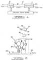
- Figure 1is a schematic block diagram of a microprocessor in a control system for an automatic transmission that includes multiple speed ratio gearing and a hydrokinetic torque converter having a lock-up clutch.
- Figure 2is a logic flow diagram showing the adaptive torque based power-on method according to the present invention.
- air and fuelare inducted by an internal combustion engine 10, which drives a shaft connecting the engine output and transmission 11 input. That shaft rotates at the speed of the engine and carries the magnitude of torque produced by the engine minus torque that drives vehicle accessories such as an air conditioning compressor, or power steering pump, electrical power production loads, etc.
- Both the engine 10 and transmission 11are coupled to an electronic engine control module 12, which includes a microprocessor 50, input conditioning circuit 56, an electronic memory 62 containing various control algorithms for processing spark timing input, exhaust gas recirculation rate input, percent methanol fuel input, air/fuel ratio input, engine RPM input, engine air charge input, engine coolant temperature, firing cylinder indication input, engine operating hours, power steering pressure, timer input, air conditioning head pressure or air change temperature input, and a flag indicating whether the air conditioning compressor is on or off.
- engine operating parameters and other such parametersare described in U.S. Patent No. 5,241,855, which is owned by the assignee of the present invention.
- a method for determining engine torqueis described in U.S. Patent No. 5,241,855.
- the microprocessor 50 shown in Figure 3is an integrated processor supplied with signals representing engine throttle position, engine speed, engine coolant temperature, torque converter speed, vehicle speed, a selected range of a gear selector, throttle valve pressure, the state of the selected transmission operating modes 52, the state of a brake switch 54, and signals representing the state of other operating parameters.
- Information conveyed by these input signalsis conditioned by input conditioning circuitry 56 and transmitted on data bus 58 to a central processing unit 60 accessible to electronic memory 62.
- the electronic memorycontains control transmission algorithms for controlling gear shift scheduling, electronic pressure control EPC, and engagement and disengagement of the torque converter bypass clutch 82.
- the processing unitrecalls information and control algorithms from electronic memory 62, executes the algorithms, and produces output signals carried on data bus 64 to output driver circuits 66, which produce electronic signals from the signals produced by the microprocessor.
- the output signalsdrive electrical solenoid-operated valves 70, 72, 74, 76, 78 located in an hydraulic valve body 68 adapted to respond to the output signals.
- the results of logical and arithmetic computations executed by the processorare stored in RAM, which is addressed, erased, rewritten, or changed in accordance with logic of the control algorithms. Certain values are stored in keep alive memory KAM, whose contents are maintained despite opening the engine ignition switch, provided the battery remains connected to the power supply.
- the algorithms that control operation of the transmissionare divided into several control modules executed sequentially in a known fashion during a background pass.
- the algorithms of each moduleare executed sequentially just as the modules themselves are executed sequentially.
- Information that results from the sensor input data and information stored in memory and learned from previous executions of the algorithmsis used during execution of the control algorithms to produce electronic signals present at the output ports of the microprocessor.
- the lock-up clutch 82 of a torque converter 84is alternately hard-locked or soft-locked (modulated) by directing hydraulic fluid through converter bypass-clutch control valve 86, which is supplied with regulated line pressure in line 88.
- a variable pressure valve 92is supplied with constant pressure through line 94 from a solenoid-pressure regulator valve and is controlled by a pulse-width modulated (PWM) signal applied to solenoid 78 from the microprocessor output.
- PWMpulse-width modulated
- Valve 86produces a pressure difference across bypass clutch 82.
- clutch 82is hard-locked, a direct mechanical connection between impeller 96 and turbine 98 is produced.
- the impeller of torque converter 84is driven from the crankshaft 100 of an engine, and turbine 98 drives a transmission input shaft 102.
- clutch 82is disengaged, the turbine is driven hydrodynamically by the impeller.
- the transmission oil temperatureis compared to a predetermined reference temperature to determine whether the transmission is at a sufficiently high temperature. Alternatively the elapsed run time can be compared to the length of a predetermined reference period for the same purpose. If the transmission temperature is below approximately -7°C (20°F), control passes to 106 where a calibrated scalar torque value, approximately 9.6 m-kg (70 ft-lb.), is used as the power-on value, and the adaptive torque base routine is exited at 108.
- a calibrated scalar torque valueapproximately 9.6 m-kg (70 ft-lb.
- upper and lower limits for engine torque corresponding to the power-on thresholdare set at 110, the range being approximately between 1.4 - 8.3 m-kg (10-60 ft-lb.).
- Keep alive memory KAMis used to store pertinent values determined by the control algorithm so that the values are obtained and not lost when the ignition switch is turned to the off position.
- An inquiryis made at 112 to determine whether KAM contains a power-on torque magnitude from a previous execution of the control algorithm. If so, at 114 that value is recalled from KAM and is used for the power-on determination. If, however, the power-on torque magnitude is absent, either because the battery was disconnected from the electrical power supply since the last execution of the algorithm or because there has been no prior execution of the control algorithm, at 116 a calibrated based torque magnitude for the power-on condition is determined and used during the current execution of the control algorithm.
- the vehicle's deceleration rateis compared to a calibrated or predetermined reference deceleration. If the vehicle decelerates at a rate that exceeds the calibrated value, control passes to 120 where the control algorithm is exited. If the test at statement 118 is positive, control passes to 122.
- Calibratable limits for the rate of deceleration and speed ratioare used to limit the vehicle conditions so that the tests will run repeatedly.
- a minimum throttle position inputis included to prevent at 122 a power-on indication when the vehicle is stopped in gear and idling.
- the state of the torque converter bypass clutchmust be open or unlocked, and the speed ratio across the torque converter must be within predetermined limits, preferably between 0.97 and 1.02. It has been determined that the powertrain torque does not change rapidly when this speed ratio is within the specified limits. However, when the speed ratio is below 0.97, the transmission loads the engine and the torque carried by the engine output shaft 13 can change rapidly.
- test at statement 122determines whether the torque produced by the engine is not changing rapidly and that the power-on condition can be sensed with a high level of precision. If the test at statement 122 is failed, control again passes to 120 where execution of this algorithm is terminated.
- the present engine torque magnitudeas determined by mapping its value with reference to engine and vehicle parameters, or using a torque sensor on the engine shaft, is saved in KAM and a sample counter is incremented at 124.
- statement 126directs control to statement 128 where it is determined whether all of the saved torque magnitudes are within a predetermined range of each other, preferably about 0.7 m-kg (5.0 ft-lb.) If the saved values are not within that tolerance range, the sample counter and saved values are cleared from memory at 130 and control exits the algorithm at 132. If the test result at 128 is negative, at 130 the counter is zeroed and the saved torque values are deleted from memory.
- the saved torque magnitudesare compared to an acceptable range of torque magnitudes, preferably 1.4 - 6.9 m-kg (10-50 ft-lb). If any saved torque magnitude is outside those limits, control passes to statement 136 where it is determined whether any saved torque magnitude is above the upper limit. If so, the power-on torque magnitude is set equal to the high limit at 138, and control passes to statement 140. If no saved torque magnitude fails the high limit test at 136, at 142 the power-on torque magnitude is set equal to the low adaptive limit plus adder torque that accounts for accessory drive and electric power loads currently applied to the engine. Then control passes to statement 140.
- the adder torque valuesare calibrated torque magnitudes used to provide a margin of safety and to compensate for loads associated with their conditioning compressor and other accessory power requirements.
- the magnitude of these adder torque loadsis determined by mapping operating parameters of the accessories and vehicle operating conditions.
- the power-on torque magnitudeis set, at statement 144, equal to the maximum of the saved torque magnitudes increased by the adder torque values.
- Statement 140clears the sample counter and the saved torque magnitudes. Execution of the control algorithm ends at statement 146.
- the onset of the power-on conditiondiscounts the torque values present when the transmission operating temperature is too low, when the vehicle is decelerating too quickly, the torque converter is locked or partially locked, and the speed ratio is outside of a range of tolerance close to unity.
- the method of this inventionrelies on the speed ratio across an open torque converter being at or very near 1.0. Therefore the power flow through the powertrain is at or near zero. The optimum time for those sampling conditions to occur in the vehicle is at very low driver demand decelerations with the torque converter unlocked, especially in the upper gear ranges. As long as the speed ratio is approximately 1.0, a reliable power-on torque magnitude can be learned.
Landscapes
- Engineering & Computer Science (AREA)
- General Engineering & Computer Science (AREA)
- Mechanical Engineering (AREA)
- Control Of Transmission Device (AREA)
- Control Of Fluid Gearings (AREA)
Description
- This invention relates control of a powertrain in anmotor vehicle. More particularly it pertains to determiningincipient positive torque in a powertrain, i.e., thethreshold of a power-on condition.
- The powertrain of a motor vehicle is tested accordingto a procedure defined by the federal government forcompliance with governmental standards including conformancewith onboard diagnostic capability (the OBD II teststandard). During execution of the federal test procedure,it is necessary to determine the torque produced by theengine of the powertrain. Conventionally, this torquemagnitude is determined from a calibratable scalar valueinferred by mapping engine torque magnitudes conforming to arange of engine parameters including throttle position,engine speed, MAP, temperature, etc. Preferably the enginetorque determined in this way should be approximately 6.9 m-kg (50 ft-lb.)in order for the OBD II test to be conducted. However,variations in the vehicle weight, the gear ratio of the axleand performance variations associated with the service lifeof the powertrain affect the power-on threshold point, andin that way influence whether the calibrated scalar torqueestimate is sufficiently high to permit federal testing tooccur.
- It is preferable to know precisely the threshold of thepower-on condition rather than to arbitrarily estimate orguess a conservatively high torque magnitude. For example,when a fairly highly conservative torque magnitude isassumed for the threshold of the power-on condition, a largeportion of the operating range of the federal test procedurecan fail to run.
- It is preferable that a control of a powertrain becapable of determining precisely the onset of a power-oncondition, and that the control adapt to variations invehicle gross weight, axle ratio, and the effects of service life and other vehicle-to-vehicle variations that influencethe threshold of the power-on condition.
- The federal test procedure provides two successivetests to detect a predetermined failure condition so thatthe vehicle onboard diagnostic system can demonstrate itsability to detect the failure and to produce an accurateindication thereof to a vehicle operator. If the diagnosticsystem fails to detect and indicate the failure, the vehicleis determined to be non-compliant with a federal onboarddiagnostic standard.
- Typically the calculation of inferred'torque into andout of the automatic transmission is not accurate at lowtorque levels due to vehicle variations and mappinginaccuracies. Since many of the functional tests used forOBDII diagnostics require a power-on indication to run,proper power-on indication is crucial, especially whenrunning the federal test procedure drive cycle for OBDIIcompliance, which tends to run at a fairly low torque level.
- US patent No 5 557 519 describes apparatus fordetecting the running resistance of a vehicle comprisingtorque detecting means to detect an output torque of theengine and correcting means for correcting the engine torquebased on the temperature of the engine. Accelerationcalculating means calculate acceleration of the vehicle andrunning resistance calculating means calculates the runningresistance on the basis of the corrected engine torque thevehicle acceleration and the overall weight of the vehicle.
- EP-A-0 939 212 discloses the features of the preamble of
claim 1 and describes a method for the correction ofa mathematically determined torque in a drive train of amotor vehicle. The method comprises establishing a set ofvehicle operating parameters at which an actual torqueapplied to a motor crankshaft is equal to zero, detectingthe occurrence of those parameters and mathematicallydetermining the torque associated with the detection of theoccurrence of those parameters. The method then determinesthe difference between the mathematically determined torqueand actual zero torque associated with the vehicle operating parameters and uses the difference as a control factor tocorrect further mathematical calculations of torque. - According to the present invention; there is nowprovided a method for determining the power-on torquemagnitude in a powertrain of a motor vehicle having anengine, and an automatic transmission having a torqueconverter that includes a bypass clutch for mechanicallyconnecting and disconnecting the impeller and turbine of thetorque converter, the impeller connected to the engine, theturbine connected to a transmission input shaft, comprisingthe steps of: recording data corresponding to periods whenthe torque converter clutch is disengaged; recording datacorresponding to periods when the speed ratio across thetorque converter is substantially at unity; recording datacorresponding to periods when the rate of vehicledeceleration is lower than a predetermined decelerationrate; determining the magnitude of torque produced by theengine; and recording successive engine torque magnitudes;characterised by; disregarding the recorded torquemagnitudes, if any of the recorded torque magnitudes isgreater than a predetermined magnitude from the recordedtorque magnitudes; setting the power-on torque magnitudeequal to the maximum stored torque magnitude, if allrecorded torque magnitudes are within a predetermined rangeof torque magnitudes; adding to the maximum recorded torquemagnitude the corresponding magnitude of engine torquecurrently driving accessory equipment; and using the sum ofthe torque magnitudes as the power-on torque magnitude.
- Figure 1 is a schematic block diagram of amicroprocessor in a control system for an automatictransmission that includes multiple speed ratio gearing anda hydrokinetic torque converter having a lock-up clutch.
- Figure 2 is a logic flow diagram showing the adaptivetorque based power-on method according to the presentinvention.
- Referring to Figures 1 and 3, air and fuel are inductedby an
internal combustion engine 10, which drives a shaftconnecting the engine output andtransmission 11 input. Thatshaft rotates at the speed of the engine and carries themagnitude of torque produced by the engine minus torque thatdrives vehicle accessories such as an air conditioningcompressor, or power steering pump, electrical powerproduction loads, etc. Both theengine 10 andtransmission 11 are coupled to an electronicengine control module 12,which includes amicroprocessor 50,input conditioningcircuit 56, anelectronic memory 62 containing variouscontrol algorithms for processing spark timing input,exhaust gas recirculation rate input, percent methanol fuelinput, air/fuel ratio input, engine RPM input, engine aircharge input, engine coolant temperature, firing cylinderindication input, engine operating hours, power steeringpressure, timer input, air conditioning head pressure or airchange temperature input, and a flag indicating whether theair conditioning compressor is on or off. These engineoperating parameters and other such parameters are describedin U.S. Patent No. 5,241,855, which is owned by the assigneeof the present invention. A method for determining enginetorque is described in U.S. Patent No. 5,241,855. - The
microprocessor 50 shown in Figure 3 is anintegrated processor supplied with signals representingengine throttle position, engine speed, engine coolanttemperature, torque converter speed, vehicle speed, aselected range of a gear selector, throttle valve pressure,the state of the selectedtransmission operating modes 52,the state of abrake switch 54, and signals representing thestate of other operating parameters. Information conveyedby these input signals is conditioned byinput conditioningcircuitry 56 and transmitted ondata bus 58 to acentralprocessing unit 60 accessible toelectronic memory 62. Theelectronic memory contains control transmission algorithmsfor controlling gear shift scheduling, electronic pressure control EPC, and engagement and disengagement of the torqueconverter bypass clutch 82. The processing unit recallsinformation and control algorithms fromelectronic memory 62, executes the algorithms, and produces output signalscarried ondata bus 64 tooutput driver circuits 66, whichproduce electronic signals from the signals produced by themicroprocessor. The output signals drive electricalsolenoid-operatedvalves hydraulic valve body 68 adapted to respond to the outputsignals. - The results of logical and arithmetic computationsexecuted by the processor are stored in RAM, which isaddressed, erased, rewritten, or changed in accordance withlogic of the control algorithms. Certain values are storedin keep alive memory KAM, whose contents are maintaineddespite opening the engine ignition switch, provided thebattery remains connected to the power supply.
- The algorithms that control operation of thetransmission are divided into several control modulesexecuted sequentially in a known fashion during a backgroundpass. The algorithms of each module are executedsequentially just as the modules themselves are executedsequentially. Information that results from the sensorinput data and information stored in memory and learned fromprevious executions of the algorithms is used duringexecution of the control algorithms to produce electronicsignals present at the output ports of the microprocessor.
- Referring now to Figure 2, the lock-
up clutch 82 of atorque converter 84 is alternately hard-locked or soft-locked(modulated) by directing hydraulic fluid throughconverter bypass-clutch control valve 86, which is suppliedwith regulated line pressure inline 88. Avariablepressure valve 92 is supplied with constant pressure throughline 94 from a solenoid-pressure regulator valve and iscontrolled by a pulse-width modulated (PWM) signal appliedtosolenoid 78 from the microprocessor output. Valve 86produces a pressure difference acrossbypass clutch 82. Whenclutch 82 is hard-locked, a direct mechanicalconnection betweenimpeller 96 andturbine 98 is produced.The impeller oftorque converter 84 is driven from thecrankshaft 100 of an engine, andturbine 98 drives atransmission input shaft 102. Whenclutch 82 is disengaged,the turbine is driven hydrodynamically by the impeller. - The method of the present invention for determining theengine torque corresponding to the onset of positive torqueat the transmission input, i.e., the threshold of the power-oncondition, is described next with reference to Figure 4.At 104, the transmission oil temperature is compared to apredetermined reference temperature to determine whether thetransmission is at a sufficiently high temperature.Alternatively the elapsed run time can be compared to thelength of a predetermined reference period for the samepurpose. If the transmission temperature is belowapproximately -7°C (20°F), control passes to 106 where a calibratedscalar torque value, approximately 9.6 m-kg (70 ft-lb.), is used as thepower-on value, and the adaptive torque base routine isexited at 108.
- If the transmission temperature is sufficiently high,upper and lower limits for engine torque corresponding tothe power-on threshold are set at 110, the range beingapproximately between 1.4 - 8.3 m-kg (10-60 ft-lb.).
- Keep alive memory KAM is used to store pertinent valuesdetermined by the control algorithm so that the values areobtained and not lost when the ignition switch is turned tothe off position. An inquiry is made at 112 to determinewhether KAM contains a power-on torque magnitude from aprevious execution of the control algorithm. If so, at 114that value is recalled from KAM and is used for the power-ondetermination. If, however, the power-on torque magnitudeis absent, either because the battery was disconnected fromthe electrical power supply since the last execution of thealgorithm or because there has been no prior execution ofthe control algorithm, at 116 a calibrated based torque magnitude for the power-on condition is determined and usedduring the current execution of the control algorithm.
- In order to prevent potential inaccuracy in the power-ontorque magnitude determined by this algorithm, at 118 thevehicle's deceleration rate is compared to a calibrated orpredetermined reference deceleration. If the vehicledecelerates at a rate that exceeds the calibrated value,control passes to 120 where the control algorithm is exited.If the test at
statement 118 is positive, control passes to122. - Calibratable limits for the rate of deceleration andspeed ratio are used to limit the vehicle conditions so thatthe tests will run repeatedly. A minimum throttle positioninput is included to prevent at 122 a power-on indicationwhen the vehicle is stopped in gear and idling. Also thestate of the torque converter bypass clutch must be open orunlocked, and the speed ratio across the torque convertermust be within predetermined limits, preferably between 0.97and 1.02. It has been determined that the powertrain torquedoes not change rapidly when this speed ratio is within thespecified limits. However, when the speed ratio is below0.97, the transmission loads the engine and the torquecarried by the
engine output shaft 13 can change rapidly.Therefore if the tests atstatement 122 are passed there isa high level of confidence that the torque produced by theengine is not changing rapidly and that the power-oncondition can be sensed with a high level of precision. Ifthe test atstatement 122 is failed, control again passes to120 where execution of this algorithm is terminated. - If the tests of
statement 122 are passed, the presentengine torque magnitude, as determined by mapping its valuewith reference to engine and vehicle parameters, or using atorque sensor on the engine shaft, is saved in KAM and asample counter is incremented at 124. - If the number of saved torque magnitudes, the countstored in a sample counter, equals or exceed a predeterminedreference count,
statement 126 directs control tostatement 128 where it is determined whether all of the saved torquemagnitudes are within a predetermined range of each other,preferably about 0.7 m-kg (5.0 ft-lb.) If the saved values are notwithin that tolerance range, the sample counter and savedvalues are cleared from memory at 130 and control exits thealgorithm at 132. If the test result at 128 is negative, at130 the counter is zeroed and the saved torque values aredeleted from memory. - If the saved torque values are within the tolerancerange, at 134 the saved torque magnitudes are compared to anacceptable range of torque magnitudes, preferably 1.4 - 6.9 m-kg (10-50 ft-lb).If any saved torque magnitude is outside those limits,control passes to
statement 136 where it is determinedwhether any saved torque magnitude is above the upper limit.If so, the power-on torque magnitude is set equal to thehigh limit at 138, and control passes tostatement 140. Ifno saved torque magnitude fails the high limit test at 136,at 142 the power-on torque magnitude is set equal to the lowadaptive limit plus adder torque that accounts for accessorydrive and electric power loads currently applied to theengine. Then control passes tostatement 140. - The adder torque values are calibrated torquemagnitudes used to provide a margin of safety and tocompensate for loads associated with their conditioningcompressor and other accessory power requirements. Themagnitude of these adder torque loads is determined bymapping operating parameters of the accessories and vehicleoperating conditions.
- If the inquiry at
statement 134 is positive, the power-ontorque magnitude is set, atstatement 144, equal to themaximum of the saved torque magnitudes increased by theadder torque values. Statement 140 clears the sample counter and the savedtorque magnitudes. Execution of the control algorithm endsat statement 146.- In this way, the onset of the power-on conditiondiscounts the torque values present when the transmission operating temperature is too low, when the vehicle isdecelerating too quickly, the torque converter is locked orpartially locked, and the speed ratio is outside of a rangeof tolerance close to unity.
- The method of this invention relies on the speed ratioacross an open torque converter being at or very near 1.0.Therefore the power flow through the powertrain is at ornear zero. The optimum time for those sampling conditionsto occur in the vehicle is at very low driver demanddecelerations with the torque converter unlocked, especiallyin the upper gear ranges. As long as the speed ratio isapproximately 1.0, a reliable power-on torque magnitude canbe learned.
Claims (7)
- A method for determining the power-on torquemagnitude in a powertrain of a motor vehicle having anengine (10), and an automatic transmission (11) having atorque converter (84) that includes a bypass clutch (82) formechanically connecting and disconnecting the impeller (96)and turbine (98) of the torque converter (84), the impeller(96) connected to the engine (10), the turbine (98)connected to a transmission input shaft (102), comprisingthe steps of:characterised by;recording data corresponding to periods when the torqueconverter clutch (82) is disengaged;recording data corresponding to periods when the speedratio across the torque converter (84) is substantially atunity;recording data corresponding to periods when the rateof vehicle deceleration is lower than a predetermineddeceleration rate;determining the magnitude of torque produced by theengine (10); andrecording successive engine torque magnitudes;
disregarding the recorded torque magnitudes, if any ofthe recorded torque magnitudes is greater than apredetermined magnitude from the recorded torque magnitudes;
setting the power-on torque magnitude equal to themaximum stored torque magnitude, if all recorded torquemagnitudes are within a predetermined range of torquemagnitudes;
adding to the maximum recorded torque magnitude thecorresponding magnitude of engine torque currently drivingaccessory equipment; and
using the sum of the torque magnitudes as the power-ontorque magnitude. - The method of claim 1, wherein the step ofrecording data corresponding to periods when the torqueconverter clutch (82) is disengaged comprises repetitivelydetermining that the torque converter clutch (82) isdisengaged;
the step of recording data corresponding to periodswhen the speed ratio across the torque converter (84) issubstantially at unity comprises repetitively determiningthat the speed ratio across the torque converter (84) iswithin a predetermined speed range;
the step of recording data corresponding to periodswhen the rate of vehicle deceleration is lower than apredetermined deceleration rate comprises repetitivelydetermining that the rate of vehicle deceleration is lowerthan a predetermined deceleration rate;
the step of determining the magnitude of torqueproduced by the engine (10) comprises repetitivelydetermining the magnitude of torque produced by the engine(10);
the step of recording successive engine torquemagnitudes comprises repetitively storing successive enginetorque magnitudes in retrievable electronic memory (62); and
the step of disregarding the recorded torquemagnitudes, if any of the recorded torque magnitudes isgreater than a predetermined magnitude from the recordedtorque magnitudes, comprises deleting from memory (62) thestored torque magnitudes, if any of the stored torquemagnitudes is greater than a predetermined magnitude fromthe other stored torque magnitudes. - The method of claim 2, further comprisingrepetitively determining that the transmission oiltemperature is greater than a predetermined minimumtemperature.
- The method of either claim 2 or claim 3, furthercomprising repetitively determining that the position of the engine throttle is greater than a predetermined minimumthrottle position.
- The method of any preceding claim, furthercomprising:setting the power-on torque magnitude equal to alargest torque magnitude of the predetermined range oftorque magnitudes if any of the stored torque magnitudes isgreater than the predetermined range of torque magnitudes;andusing the power-on the torque magnitude during a testof the powertrain.
- The method of claim 5, further comprising:setting the power-on torque magnitude equal to thelargest of the stored torque magnitudes if any of the storedtorque magnitudes is less than a predetermined range oftorque magnitudes;adding to the maximum stored torque magnitude thecorresponding magnitude of engine torque currently drivingaccessory equipment;deleting the stored torque magnitudes from memory (62);andusing the sum of the torque magnitudes as the power-ontorque magnitude.
- The method of claim 1, further comprising recordingdata corresponding to periods when the position of theengine throttle is greater than a predetermined minimumthrottle position.
Applications Claiming Priority (2)
| Application Number | Priority Date | Filing Date | Title |
|---|---|---|---|
| US09/551,427US6278925B1 (en) | 2000-04-18 | 2000-04-18 | Adaptive method for determining onset of positive torque in a powertrain having an automatic transmission |
| US551427 | 2000-04-18 |
Publications (2)
| Publication Number | Publication Date |
|---|---|
| EP1148274A1 EP1148274A1 (en) | 2001-10-24 |
| EP1148274B1true EP1148274B1 (en) | 2004-06-30 |
Family
ID=24201221
Family Applications (1)
| Application Number | Title | Priority Date | Filing Date |
|---|---|---|---|
| EP01303475AExpired - LifetimeEP1148274B1 (en) | 2000-04-18 | 2001-04-12 | Adaptive method for determining onset of positive torque in a powertrain having an automatic transmission |
Country Status (3)
| Country | Link |
|---|---|
| US (1) | US6278925B1 (en) |
| EP (1) | EP1148274B1 (en) |
| DE (1) | DE60104050T2 (en) |
Families Citing this family (10)
| Publication number | Priority date | Publication date | Assignee | Title |
|---|---|---|---|---|
| US6427109B1 (en)* | 2001-10-11 | 2002-07-30 | Ford Global Technologies, Inc. | Powertrain torque estimate |
| DE10160480A1 (en)* | 2001-12-08 | 2003-06-26 | Bosch Gmbh Robert | Method and appliance for coordinated control of mechanical, electrical and thermal power flow in motor vehicle by optimizing desired power requirements based on actual power outputs |
| DE10230765A1 (en)* | 2002-07-09 | 2004-01-22 | Zf Friedrichshafen Ag | Device for evaluating vehicle, drive and operating parameters |
| WO2005119096A2 (en)* | 2004-06-01 | 2005-12-15 | Carne Gary S | Transmission pressure modulation by orificed check valve |
| CA2479890A1 (en)* | 2004-09-27 | 2006-03-27 | Samuel Beaudoin | High efficiency generator system and continuously variable transmission therefor |
| KR20080016148A (en)* | 2006-08-17 | 2008-02-21 | 현대자동차주식회사 | Propagation method of learning value of automatic transmission |
| US7650219B2 (en)* | 2007-11-02 | 2010-01-19 | Gm Global Technology Operations, Inc. | Reserve torque management for engine speed control |
| US7846063B2 (en)* | 2007-11-29 | 2010-12-07 | Cnh America Llc | Automatic calibration of a torque measuring system |
| US8311721B2 (en)* | 2008-03-26 | 2012-11-13 | GM Global Technology Operations LLC | Reserve torque for lean equivalence ratio requests |
| CN109000833B (en)* | 2018-06-07 | 2021-01-29 | 青岛迈金智能科技有限公司 | Method for converting torque of current rotating speed of electromagnetic resistance-adding system |
Family Cites Families (12)
| Publication number | Priority date | Publication date | Assignee | Title |
|---|---|---|---|---|
| US4535412A (en)* | 1981-11-06 | 1985-08-13 | Ford Motor Company | Drivetrain torque determination using torque converter characteristics |
| JP2767793B2 (en)* | 1987-04-20 | 1998-06-18 | 三菱自動車工業株式会社 | Input power on / off determination method for automatic transmission |
| US5046383A (en)* | 1990-07-16 | 1991-09-10 | General Motors Corporation | Acceleration-based control of power-on clutch-to-clutch upshifting in an automatic transmission |
| JPH04191132A (en)* | 1990-11-26 | 1992-07-09 | Mitsubishi Electric Corp | Running resistance detecting device of vehicle |
| US5241855A (en) | 1991-10-31 | 1993-09-07 | Ford Motor Company | Method and apparatus for inferring engine torque |
| DE4304779B4 (en)* | 1992-06-20 | 2005-11-24 | Robert Bosch Gmbh | Device for controlling the torque to be delivered by a drive unit of a vehicle |
| JP3524161B2 (en)* | 1994-07-25 | 2004-05-10 | 株式会社日立製作所 | Control method and control device for automatic transmission, and automobile |
| US5477950A (en) | 1994-11-04 | 1995-12-26 | Ford Motor Company | Noise and vibration reduction in a torque converter clutch assembly |
| JP3573368B2 (en)* | 1995-02-21 | 2004-10-06 | 本田技研工業株式会社 | Vehicle engine output control device |
| US5910176A (en)* | 1996-10-28 | 1999-06-08 | Caterpillar Inc. | Apparatus and method for calibrating a computer based model of an attribute of a mobile machine |
| GB2329713A (en)* | 1997-09-30 | 1999-03-31 | Ford Global Tech Inc | IC engine net torque calculator |
| DE19808167C1 (en)* | 1998-02-27 | 1999-08-26 | Daimler Chrysler Ag | Method for correcting a calculated torque in the drive train of a motor vehicle |
- 2000
- 2000-04-18USUS09/551,427patent/US6278925B1/ennot_activeExpired - Lifetime
- 2001
- 2001-04-12EPEP01303475Apatent/EP1148274B1/ennot_activeExpired - Lifetime
- 2001-04-12DEDE60104050Tpatent/DE60104050T2/ennot_activeExpired - Fee Related
Also Published As
| Publication number | Publication date |
|---|---|
| US6278925B1 (en) | 2001-08-21 |
| DE60104050D1 (en) | 2004-08-05 |
| DE60104050T2 (en) | 2005-11-10 |
| EP1148274A1 (en) | 2001-10-24 |
Similar Documents
| Publication | Publication Date | Title |
|---|---|---|
| US6035252A (en) | Engine torque control | |
| EP0804681B1 (en) | Method and system for engine control | |
| US8608374B2 (en) | Outside air temperature sensor diagnostic systems for a vehicle | |
| US6754573B2 (en) | Vehicle and engine control system and method | |
| EP2216568B1 (en) | Abnormality determination apparatus and abnormality determination method for oil temperature sensor | |
| EP1148274B1 (en) | Adaptive method for determining onset of positive torque in a powertrain having an automatic transmission | |
| EP0276003A2 (en) | Fail-safe method and system for automotive engines | |
| US5243852A (en) | Failure diagnosis device for an automotive engine | |
| CN101245742A (en) | Method for on-board diagnosis of cold start emissions reduction control strategy | |
| US4807497A (en) | System for integrally controlling automatic transmission and engine | |
| EP0751323B1 (en) | Automatic transmission hot mode management | |
| US5983859A (en) | Method for controlling an internal combustion engine | |
| EP1302703B1 (en) | A method and system for controlling a powertrain | |
| US6397668B1 (en) | Fuel level monitor | |
| US6378505B1 (en) | Fuel tank pressure control system | |
| US5599254A (en) | Method and apparatus for diagnosing a fault in a lock-up mechanism of a torque converter fitted to an automatic transmission | |
| US4969099A (en) | Double-detecting, trouble-judging and failsafe devices in system for integrally controlling automatic transmission and engine | |
| US5189908A (en) | Testing apparatus for engine driven automotive component with feature of precise simulation of engine transition state | |
| US7217222B2 (en) | Method and system for inferring and controlling transmission fluid temperature | |
| EP0484553A1 (en) | Output display device in engine for motor vehicle | |
| US6604412B2 (en) | Sensor diagnostics | |
| JPH04171249A (en) | Misfire detector of internal combustion engine for vehicle | |
| US5511412A (en) | Method of diagnosing an idle speed control system | |
| US6550319B1 (en) | Fault diagnostic for an internal combustion engine having air assisted injectors | |
| JP3101789B2 (en) | Lockup mechanism failure diagnosis device |
Legal Events
| Date | Code | Title | Description |
|---|---|---|---|
| PUAI | Public reference made under article 153(3) epc to a published international application that has entered the european phase | Free format text:ORIGINAL CODE: 0009012 | |
| AK | Designated contracting states | Kind code of ref document:A1 Designated state(s):AT BE CH CY DE DK ES FI FR GB GR IE IT LI LU MC NL PT SE TR Kind code of ref document:A1 Designated state(s):DE FR GB | |
| AX | Request for extension of the european patent | Free format text:AL;LT;LV;MK;RO;SI | |
| 17P | Request for examination filed | Effective date:20020311 | |
| AKX | Designation fees paid | Free format text:DE FR GB | |
| 17Q | First examination report despatched | Effective date:20030523 | |
| GRAP | Despatch of communication of intention to grant a patent | Free format text:ORIGINAL CODE: EPIDOSNIGR1 | |
| RIC1 | Information provided on ipc code assigned before grant | Ipc:7F 16H 59/14 B Ipc:7F 16H 59:48 Z Ipc:7B 60K 41/10 A Ipc:7F 16H 59:46 Z | |
| GRAS | Grant fee paid | Free format text:ORIGINAL CODE: EPIDOSNIGR3 | |
| RAP1 | Party data changed (applicant data changed or rights of an application transferred) | Owner name:FORD GLOBAL TECHNOLOGIES, LLC | |
| GRAA | (expected) grant | Free format text:ORIGINAL CODE: 0009210 | |
| AK | Designated contracting states | Kind code of ref document:B1 Designated state(s):DE FR GB | |
| PG25 | Lapsed in a contracting state [announced via postgrant information from national office to epo] | Ref country code:FR Free format text:LAPSE BECAUSE OF FAILURE TO SUBMIT A TRANSLATION OF THE DESCRIPTION OR TO PAY THE FEE WITHIN THE PRESCRIBED TIME-LIMIT Effective date:20040630 | |
| REG | Reference to a national code | Ref country code:GB Ref legal event code:FG4D | |
| REF | Corresponds to: | Ref document number:60104050 Country of ref document:DE Date of ref document:20040805 Kind code of ref document:P | |
| PGFP | Annual fee paid to national office [announced via postgrant information from national office to epo] | Ref country code:FR Payment date:20050401 Year of fee payment:5 | |
| PLBE | No opposition filed within time limit | Free format text:ORIGINAL CODE: 0009261 | |
| STAA | Information on the status of an ep patent application or granted ep patent | Free format text:STATUS: NO OPPOSITION FILED WITHIN TIME LIMIT | |
| 26N | No opposition filed | Effective date:20050331 | |
| EN | Fr: translation not filed | ||
| PGFP | Annual fee paid to national office [announced via postgrant information from national office to epo] | Ref country code:GB Payment date:20080317 Year of fee payment:8 | |
| PGFP | Annual fee paid to national office [announced via postgrant information from national office to epo] | Ref country code:DE Payment date:20080430 Year of fee payment:8 | |
| GBPC | Gb: european patent ceased through non-payment of renewal fee | Effective date:20090412 | |
| PG25 | Lapsed in a contracting state [announced via postgrant information from national office to epo] | Ref country code:DE Free format text:LAPSE BECAUSE OF NON-PAYMENT OF DUE FEES Effective date:20091103 | |
| PG25 | Lapsed in a contracting state [announced via postgrant information from national office to epo] | Ref country code:GB Free format text:LAPSE BECAUSE OF NON-PAYMENT OF DUE FEES Effective date:20090412 |