EP1147787B2 - Flat-folded personal respiratory protection devices and processes for preparing same - Google Patents
Flat-folded personal respiratory protection devices and processes for preparing sameDownload PDFInfo
- Publication number
- EP1147787B2 EP1147787B2EP01202599.5AEP01202599AEP1147787B2EP 1147787 B2EP1147787 B2EP 1147787B2EP 01202599 AEP01202599 AEP 01202599AEP 1147787 B2EP1147787 B2EP 1147787B2
- Authority
- EP
- European Patent Office
- Prior art keywords
- panel
- protection device
- respiratory protection
- fold
- personal respiratory
- Prior art date
- Legal status (The legal status is an assumption and is not a legal conclusion. Google has not performed a legal analysis and makes no representation as to the accuracy of the status listed.)
- Expired - Lifetime
Links
- 230000000241respiratory effectEffects0.000titleclaimsabstractdescription132
- 238000000034methodMethods0.000titleclaimsdescription15
- 230000008569processEffects0.000titledescription12
- 238000003860storageMethods0.000claimsabstractdescription10
- 239000000835fiberSubstances0.000claimsdescription32
- 229920001410MicrofiberPolymers0.000claimsdescription14
- 238000001914filtrationMethods0.000claimsdescription14
- 239000003658microfiberSubstances0.000claimsdescription14
- -1polypropylenePolymers0.000claimsdescription13
- 238000004519manufacturing processMethods0.000claimsdescription9
- 239000004743PolypropyleneSubstances0.000claimsdescription8
- 229920001155polypropylenePolymers0.000claimsdescription8
- 239000013536elastomeric materialSubstances0.000claimsdescription2
- 238000005304joiningMethods0.000claimsdescription2
- 239000006261foam materialSubstances0.000claims1
- 239000000463materialSubstances0.000description32
- 238000010276constructionMethods0.000description24
- 239000006260foamSubstances0.000description7
- 210000003128headAnatomy0.000description7
- 239000000853adhesiveSubstances0.000description6
- 230000001070adhesive effectEffects0.000description6
- 238000007789sealingMethods0.000description6
- 238000013461designMethods0.000description5
- 210000000887faceAnatomy0.000description5
- 239000002245particleSubstances0.000description4
- 229920000728polyesterPolymers0.000description4
- 239000011230binding agentSubstances0.000description3
- 239000002131composite materialSubstances0.000description3
- 239000012779reinforcing materialSubstances0.000description3
- 238000007493shaping processMethods0.000description3
- 238000003466weldingMethods0.000description3
- OKTJSMMVPCPJKN-UHFFFAOYSA-NCarbonChemical compound[C]OKTJSMMVPCPJKN-UHFFFAOYSA-N0.000description2
- 239000004698PolyethyleneSubstances0.000description2
- 238000004026adhesive bondingMethods0.000description2
- 229910052782aluminiumInorganic materials0.000description2
- XAGFODPZIPBFFR-UHFFFAOYSA-NaluminiumChemical compound[Al]XAGFODPZIPBFFR-UHFFFAOYSA-N0.000description2
- 230000008901benefitEffects0.000description2
- 239000000428dustSubstances0.000description2
- 230000000694effectsEffects0.000description2
- 239000004744fabricSubstances0.000description2
- 239000011521glassSubstances0.000description2
- 238000010438heat treatmentMethods0.000description2
- 239000007788liquidSubstances0.000description2
- 238000004806packaging method and processMethods0.000description2
- 230000002093peripheral effectEffects0.000description2
- 229920000573polyethylenePolymers0.000description2
- 229920000098polyolefinPolymers0.000description2
- 229920002635polyurethanePolymers0.000description2
- 239000004814polyurethaneSubstances0.000description2
- 238000009958sewingMethods0.000description2
- NLHHRLWOUZZQLW-UHFFFAOYSA-NAcrylonitrileChemical groupC=CC#NNLHHRLWOUZZQLW-UHFFFAOYSA-N0.000description1
- IAYPIBMASNFSPL-UHFFFAOYSA-NEthylene oxideChemical compoundC1CO1IAYPIBMASNFSPL-UHFFFAOYSA-N0.000description1
- 239000004831Hot glueSubstances0.000description1
- 239000004820Pressure-sensitive adhesiveSubstances0.000description1
- 229920000297RayonPolymers0.000description1
- 229920002334SpandexPolymers0.000description1
- BZHJMEDXRYGGRV-UHFFFAOYSA-NVinyl chlorideChemical groupClC=CBZHJMEDXRYGGRV-UHFFFAOYSA-N0.000description1
- NIXOWILDQLNWCW-UHFFFAOYSA-Nacrylic acid groupChemical groupC(C=C)(=O)ONIXOWILDQLNWCW-UHFFFAOYSA-N0.000description1
- 230000001154acute effectEffects0.000description1
- 239000004840adhesive resinSubstances0.000description1
- 229920006223adhesive resinPolymers0.000description1
- 230000004075alterationEffects0.000description1
- PNEYBMLMFCGWSK-UHFFFAOYSA-Naluminium oxideInorganic materials[O-2].[O-2].[O-2].[Al+3].[Al+3]PNEYBMLMFCGWSK-UHFFFAOYSA-N0.000description1
- 238000013459approachMethods0.000description1
- 230000000712assemblyEffects0.000description1
- 238000000429assemblyMethods0.000description1
- 230000004888barrier functionEffects0.000description1
- 229920002678cellulosePolymers0.000description1
- 239000001913celluloseSubstances0.000description1
- 238000007796conventional methodMethods0.000description1
- 238000001816coolingMethods0.000description1
- 229920001577copolymerPolymers0.000description1
- 210000005069earsAnatomy0.000description1
- 229920001971elastomerPolymers0.000description1
- 238000004049embossingMethods0.000description1
- 210000001061foreheadAnatomy0.000description1
- 239000007789gasSubstances0.000description1
- 230000004313glareEffects0.000description1
- 229910052736halogenInorganic materials0.000description1
- 125000005843halogen groupChemical group0.000description1
- 230000006872improvementEffects0.000description1
- 239000004816latexSubstances0.000description1
- 229920000126latexPolymers0.000description1
- 230000013011matingEffects0.000description1
- 238000002844meltingMethods0.000description1
- 230000008018meltingEffects0.000description1
- 229910052751metalInorganic materials0.000description1
- 239000002184metalSubstances0.000description1
- 239000000203mixtureSubstances0.000description1
- 238000012986modificationMethods0.000description1
- 230000004048modificationEffects0.000description1
- 239000004745nonwoven fabricSubstances0.000description1
- 230000001473noxious effectEffects0.000description1
- 239000011236particulate materialSubstances0.000description1
- 239000004033plasticSubstances0.000description1
- 229920003023plasticPolymers0.000description1
- 229920001748polybutylenePolymers0.000description1
- 239000004417polycarbonateSubstances0.000description1
- 229920000515polycarbonatePolymers0.000description1
- 229920001195polyisoprenePolymers0.000description1
- 229920000306polymethylpentenePolymers0.000description1
- 239000011116polymethylpenteneSubstances0.000description1
- 238000007639printingMethods0.000description1
- 230000005855radiationEffects0.000description1
- 239000002964rayonSubstances0.000description1
- 238000011160researchMethods0.000description1
- 210000002345respiratory systemAnatomy0.000description1
- 230000000284resting effectEffects0.000description1
- 230000000717retained effectEffects0.000description1
- 238000004826seamingMethods0.000description1
- 238000000926separation methodMethods0.000description1
- 239000002594sorbentSubstances0.000description1
- 239000004759spandexSubstances0.000description1
- 238000010561standard procedureMethods0.000description1
- BFKJFAAPBSQJPD-UHFFFAOYSA-NtetrafluoroetheneChemical groupFC(F)=C(F)FBFKJFAAPBSQJPD-UHFFFAOYSA-N0.000description1
- 230000000930thermomechanical effectEffects0.000description1
- 229920001169thermoplasticPolymers0.000description1
- 229920002725thermoplastic elastomerPolymers0.000description1
- 239000004416thermosoftening plasticSubstances0.000description1
- 239000012780transparent materialSubstances0.000description1
- 238000010792warmingMethods0.000description1
- 210000000216zygomaAnatomy0.000description1
Images


Classifications
- A—HUMAN NECESSITIES
- A62—LIFE-SAVING; FIRE-FIGHTING
- A62B—DEVICES, APPARATUS OR METHODS FOR LIFE-SAVING
- A62B23/00—Filters for breathing-protection purposes
- A62B23/02—Filters for breathing-protection purposes for respirators
- A62B23/025—Filters for breathing-protection purposes for respirators the filter having substantially the shape of a mask
- A—HUMAN NECESSITIES
- A41—WEARING APPAREL
- A41D—OUTERWEAR; PROTECTIVE GARMENTS; ACCESSORIES
- A41D13/00—Professional, industrial or sporting protective garments, e.g. surgeons' gowns or garments protecting against blows or punches
- A41D13/05—Professional, industrial or sporting protective garments, e.g. surgeons' gowns or garments protecting against blows or punches protecting only a particular body part
- A41D13/11—Protective face masks, e.g. for surgical use, or for use in foul atmospheres
- A41D13/1107—Protective face masks, e.g. for surgical use, or for use in foul atmospheres characterised by their shape
- A41D13/1115—Protective face masks, e.g. for surgical use, or for use in foul atmospheres characterised by their shape with a horizontal pleated pocket
Definitions
- the present inventionrelates to respirators or face masks which are capable of being folded flat during storage and forming a cup-shaped air chamber over the mouth and nose of a wearer during use.
- Filtration respirators or face masksare used in a wide variety of applications when it is desired to protect a human's respiratory system from particles suspended in the air or from unpleasant or noxious gases.
- respirators or face masksare of one of two types - a molded cup-shaped form or a flat-folded form.
- the flat-folded formhas advantages in that it can be carried in a wearer's pocket until needed and re-folded flat to keep the inside clean between wearings.
- the flat-folded form of face maskhas been constructed as a fabric which is rectangular in form and has pleats running generally parallel to the mouth of the wearer, see for example US-A-4 920 960 .
- Such constructionsmay have a stiffening element to hold the face mask away from contact with the wearer's face.
- Stiffeninghas also been provided by fusing a pleat across the width of the face mask in a laminated structure or by providing a seam across the width of the face mask.
- a pleated respiratorwhich is centrally folded in the horizontal direction to form upper and lower opposed faces.
- the respiratorhas at least one horizontal pleat essentially central to the opposed faces to foreshorten the filter medium in the vertical dimension and at least one additional horizontal pleat in each of these opposed faces.
- the central pleatis shorter in the horizontal dimension relative to the pleats in the opposed faces which are shorter in the horizontal dimension relative to the maximum horizontal dimension of the filter medium.
- the central pleat together with the pleats in opposed facesform a self-supporting pocket.
- a respiratormade from a pocket of flexible filtering sheet material having a generally tapering shape with an open edge at the larger end of the pocket and a closed end at the smaller end of the pocket.
- the closed end of the pocketis formed with fold lines defining a generally quadrilateral surface comprising triangular surfaces which are folded to extend inwardly of the pocket, the triangular surfaces facing each other and being in use, relatively inclined to each other.
- More complex configurationswhich have been disclosed include a cup-shaped filtering facepiece made from a pocket of filtering sheet material having opposed side walls, a generally tapering shape with an open end at the larger end and a closed end at the smaller end.
- the edge of the pocket at the closed endis outwardly bowed, e.g. defined by intersecting straight lines and/or curved lines, and the closed end is provided with fold lines defining a surface which is folded inwardly of the closed end of the pocket to define a generally conical inwardly extending recess for rigidifying the pocket against collapse against the face of the wearer on inhalation.
- a face maskhaving an upper part and a lower part with a generally central part therebetween.
- the central part of the body portionis folded backwardly about a vertical crease or fold line which substantially divides it in half This fold or crease line, when the mask is worn, is more or less aligned with an imaginary vertical line passing through the center of the forehead, the nose and the center of the mouth.
- the upper part of the body portionextends upwardly at an angle from the upper edge of the central part so that its upper edge contacts the bridge of the nose and the cheekbone area of the face.
- the lower part of the body portionextends downwardly and in the direction of the throat form the lower edge of the center part so as to provide coverage underneath the chin of the wearer.
- the maskoverlies, but does not directly contact, the lips and mouth of the wearer.
- GB-A-2079 161also discloses face masks having a central part with a vertical crease or fold line.
- respirators or facemasksprovide a flat configuration when folded and a cup-shaped configuration when unfolded. It would be desirable however to provide a flat-folding respirator or face mask having improved sealing engagement with the wearer's face or offering improved comfort for the wearer.
- the present inventionprovides a personal respiratory protection device as defined in claim 1.
- the respiratory devices of the present inventionmay further comprise headbands or other means such as adhesive for holding the respiratory device in place on the face of the wearer, nose clips or any other means to provide good contact of the respiratory device with the nose of the wearer, exhalation valves, and other accouterments common to respirators and facemasks such as, for example, face seals, eye shields and neck coverings.
- headbands or other meanssuch as adhesive for holding the respiratory device in place on the face of the wearer, nose clips or any other means to provide good contact of the respiratory device with the nose of the wearer, exhalation valves, and other accouterments common to respirators and facemasks such as, for example, face seals, eye shields and neck coverings.
- the nose clipWhen the respiratory device is constructed with a nose clip, the nose clip may be on the outer surface of the first panel of the respiratory device and a cushioning member such as a piece of foam can be placed directly below the nose clip on the inner surface of the first panel or the nose clip may be on the inner surface of the first panel and a cushioning member can be placed covering the nose clip or when the respiratory device comprises multiple layers, the nose clip may be placed between layers.
- a cushioning membersuch as a piece of foam can be placed directly below the nose clip on the inner surface of the first panel or the nose clip may be on the inner surface of the first panel and a cushioning member can be placed covering the nose clip or when the respiratory device comprises multiple layers, the nose clip may be placed between layers.
- the respiratory devices of the present inventioninclude, for example, respirators, surgical masks, clean room masks, face shields, dust masks, breath warming masks, and a variety of other face coverings.
- the respiratory devices of the present inventioncan be designed to provide better sealing engagement with the wearer's face than some other types of cup-shaped respirators or face masks which contact the wearer's face at the periphery of the respirator at an acute angle with minimal contact region, thereby increasing discomfort to the wearer and potentially minimizing the engagement of the seal at the perimeter of the respirator.
- the processis amenable to high speed production methods and may comprise additional steps as needed for attachment of headbands, nose clips, and other typical respiratory device components.
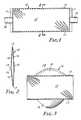
- a front view of personal respiratory protection device 10the device has a generally rectangular shape when in the folded form for storage in a package prior to use or in a wearer's pocket.
- a side view of personal respiratory protection device 10, shown in FIG. 2shows the device having a central portion 12, a first member 14 and second member 16. The central portion and the first and second members are joined, for example, as shown in FIG. 2 by folds 15 and 17, or the first and second members may be bonded or seamed to the central portion.
- the configurationis held in place by edge seals 11 and 11' which may extend from fold 15 to fold 17 as shown or they may extend partially from fold 15 to fold 17. Edge seals 11 and 11' may be substantially straight as shown or they may be curved.
- FIGS. 1 and 3also show attachment means 18, 18' for attaching, for example, a head band to hold the device in place on a wearer's face.
- the deviceis a multilayer construction, having, for example, filter media layer(s), an optional cover layer, and an optional stiffening layer, the perimeter edges of first and second members 14 and 16 are also bonded.
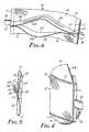
- the personal respiratory protection device 10is shown in FIGS. 3 , and 4 , where common parts are identified as in FIGS. 1 and 2 , in its opened, ready-to wear configuration having the general shape of a cup or pouch which provides the wearer with the "off-the-face" benefits of a molded cup-shaped respiratory device.
- the cup-shaped "off-the-face" design of the respiratory device of the inventionprovides a periphery region formed by edges 24 and 26 of the first and second members, respectively, for sealing the respiratory device against the face of the wearer.
- FIG. 3shows personal respiratory protection device 10 with optional nose clip 28.
- additional members 20 and 22are attached to the first and second members 14 and 16 of respiratory device 10' by folds 21 and 23 or by bonding or seaming (not shown). Additional members 20 and 22 may be sealed with central portion 12 and first and second members 14 and 16 at edge seals 11, 11', but preferably are not sealed at the edge seals as shown in Figs 5 and 6 to provide enhanced sealing at the periphery of respiratory device 10' due to the ability of the additional portions 20 and 22 to pivot at the attachment points 25 and 25'.
- FIG. 6shows respiratory device 10' with optional nose clip 28 located on additional member 20. In this embodiment, when multiple layers are used to form the respiratory device, perimeter edges of additional members 20 and 22 are also preferably bonded.
- the width of the central portion 12 of personal respiratory protection device 10 extending between edge seals 11 and 11' or bonds located in the same position as edge seals 11 and 11'is preferably about 160 to 220 mm in width, more preferably about 175 to 205 mm, most preferably about 185 to 190 mm in width.
- the height of central portion 12 of respiratory device 10 extending between folds 15 and 17is preferably about 30 to 110 mm in height, more preferably about 50 to 100 mm in height, most preferably about 75 to 80 mm in height.
- the width of first member 14 and second member 16 of respiratory device 10are preferably about the same as that of central portion 12.
- first member 14 extending from fold 15 to the peripheral edge of first member 14 of respiratory device 10 or fold 21 of respiratory device 10'is preferably about 30 to 110 mm, more preferably about 50 to 70 mm, most preferably about 55 to 65 mm.
- the depth of second member 16 extending from fold 17 to the peripheral edge of second member 16 of respiratory device 10 to fold 23 of respiratory device 10'is preferably about 30 to 110 mm, more preferably about 55 to 75 mm, most preferably about 60 to 70 mm.
- the depths of first member 14 and second member 16may be the same or different and the sum of the depths of the first and second members preferably does not exceed the height of the central portion.
- Additional members 20 and 22 in respiratory device 10'are preferably about the same width as first and second members 14 and 16.
- Additional member 20 in respiratory device 10'is preferably about 1 to 95 mm, more preferably about 5 to 40 mm, most preferably about 5 to 30 mm in depth.
- Additional member 22 of respiratory device 10'is preferably about 1 to 95 mm. more preferably about 3 to 75 mm, most preferably about 3 to 35 mm in depth.
- End edge sealsare preferably at about 1 to 25 mm, more preferably about 5-10 mm from the outer edges of central portion 12, first member 14 and second member 16 and are preferably 1 to 10 mm in width, more preferably 2 to 5 mm in width.
- the outer boundary of the unjoined edges which contact the nose, cheeks and chin of the wearer in the open configuration shown in FIGS. 3 , 4 and 6are less than the perimeter of the device in the flat folded storage state.
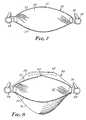
- FIGS. 7, 8 , 9 , 10, 11 and 12A further embodiment which is referred to as being elliptical in shape is shown in FIGS. 7, 8 , 9 , 10, 11 and 12 .
- respiratory device 50shown in front view in its folded, or storage configuration, includes a central portion 52, and bonds 55 and 57. Also shown are attachment means 58, 58' for attaching, for example, a head band 59 to hold the respiratory device in place on a wearer's face.
- FIG. 8respiratory device 50 is shown in front view in its ready-for-use unfolded configuration with first member 54 bonded to central portion 52 at bond 55 and second member 56 bonded to central portion 52 at bond 57.
- FIG. 8further shows a nose clip 60 on first member 54 and a protrusion 62 on central portion 52, with a comparable mating protrusion on first member 54 (not shown)
- Nose clip 60provides improved fit and protrusion 62 with its sister protrusion on first member 54 provides improved comfort and fit.
- an improvement in fitcan be obtained by folding the outer edge of first member 54 inwards, i.e., towards the face of a wearer.
- Nose clip 60if present, can be located inside the fold.
- a generally widthwise fold, or pleatcan be formed in first member 54 or in second member 56 of the respiratory device, just below the fold or bond 57.
- the outer boundary of the unjoined edges which contact the nose, cheeks and chin of the wearer in the open configuration shown in FIGS. 8 and 9are less than the perimeter of the device in the flat folded storage state.
- respiratory device 50is shown on the face of a wearer and having a cup-shaped configuration with nose clip 60 being shown in FIG. 10 , nose clip 60 and exhalation valve 64 being shown in FIG. 11 and nose clip 60' and exhalation valve 64 being shown in FIG. 12 .
- nose clips and exhalation valvescan be equally useful on the respiratory devices shown in FIGS. 1-6 .
- the width at the widest portion of central portion 52is preferably about 160 to 220 mm, more preferably about 175 to 205 mm, most preferably about 193 to 197 mm.
- the height at the highest portion of the central portion, perpendicular to the width,is preferably about 30 to 110 mm, more preferably about 50 to 100 mm, most preferably about 70 to 80 mm.
- the first and second membersare substantially the same width as the central portion.
- the depth at the deepest part of the first memberis preferably about 30 to 110 mm, more preferably about 40 to 90 mm, most preferably about 50 to 60 mm.
- the depth at the deepest part of the second memberis preferably about 30 to 110 mm, more preferably about 50 to 100 mm, most preferably about 60 to 70 mm.
- the depths of the first and second membersmay be the same or different. When the depth of the second member is greater than that of the first portion, additional protection can be provided to the chin area. By adjusting the depths of the first and second members as well as the central portion, the fit of the second member under the chin can be adjusted or the fit of the first portion over the nose can be adjusted so that the first portion rests along the length of the nose or rests predominantly on the bridge of the nose.
- the respiratory device 50'is configured such that central portion 52', first member 54' and second member 56' rest vertically on a wearer's face with the end portions 61 and 63 of central portion 52' resting on the nose and chin of the wearer.
- First member 54'is bonded to central portion 52' at bond 55' and second member 56' is bonded to central portion 52' at bond 57'.
- Attachment means 58', 58"are provided for attaching, for example, a head band 59' to hold the respiratory device in place on a wearer's face.
- the respiratory device shown in FIGS. 1-6could be similarly modified by changing the location of the attachment means 18, 18'.
- the distance between the attachment meansis preferably about 160 to 220 mm, more preferably about 170 to 190 mm for the substantially elliptical shaped device and about 175 to 195 mm for the substantially rectangular device.
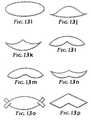
- the shape of the flat-folded personal respiratory protection devicealthough referred to as generally elliptical with regard to FIGS. 7-12 may vary greatly. It will typically not be a regular ellipse and could, for example, even approach a rhomboid.
- Various possible shapes of the folded deviceare shown in FIGS. 13(a) to 13(p) .
- a quadrant of the central portioncould have a bonded edge configuration approaching a right angle or approaching forming a straight line or a pattern comprising a combination of curves and/or straight lines.
- such a bonded edgehas a configuration such as a gentle curve as shown in FIG.
- the curvehas a radius of about 120 to 170 mm, most preferably about 140 to 150 mm.
- the shape of the first and second members and the additional portionsmay vary considerably. Each of the first and second members must be shaped such that they can be joined to the central portion as previously described.
- the shape of the unattached edge portions of the first and second membersmay also vary from straight to curvilinear as desired to achieve good fit to the wearer's face.
- the additional memberswhen present, must have an edge portion suitable for joining with the first or second edge portion as appropriate.
- the shape of the unjoined edge portionscan range from straight to curvilinear.
- the bonds connecting the central portion with the first and second members and the additional members with the first and second members, respectively,are preferably no more than about 15 mm deep from the edges of the central portion and first member or the edges of the first and second member, more preferably no more than about 10 mm deep, most preferably no more than about 5 mm deep and may be continuous or discontinuous.
- the filter media or material useful in the present invention which must comprise at least one of the central portion, first member or second membermay be comprised of a number of woven and nonwoven materials, a single or a plurality of layers, with or without an inner or outer cover or scrim, and with or without a stiffening means.
- the central portionis provided with stiffening means such as, for example, woven or nonwoven scrim, adhesive bars, printing or bonding.
- suitable filter materialinclude microfiber webs, fibrillated film webs, woven or nonwoven webs (e.g., airlaid or carded staple fibers), solution-blown fiber webs, or combinations thereof.
- Fibers useful for forming such websinclude, for example, polyolefins such as polypropylene, polyethylene, polybutylene, poly(4-methyl-1-pentene) and blends thereof, halogen substituted polyolefins such as those containing one or more chloroethylene units, or tetrafluoroethylene units, and which may also contain acrylonitrile units, polyesters, polycarbonates, polyurethanes, rosin-wool, glass, cellulose or combinations thereof
- Fibers of the filtering layerare selected depending upon the type of particulate to be filtered. Proper selection of fibers can also affect the comfort of the respiratory device to the wearer, e.g., by providing softness or moisture control.
- Webs of melt blown microfibers useful in the present inventioncan be prepared as described, for example, in Wente, Van A., "Superfine Thermoplastic Fibers” in Industrial Engineering Chemistry, Vol. 48, 1342 et seq. (1956 ) and in Report No. 4364 of the Navel Research Laboratories, published May 25, 1954, entitled “Manufacture of Super Fine Organic Fibers" by Van A. Wente et al.
- the blown microfibers in the filter media useful on the present inventionpreferably have an effective fiber diameter of from 3 to 30 micrometers, more preferably from about 7 to 15 micrometers, as calculated according to the method set forth in Davies, C.N., "The Separation of Airborne Dust Particles", Institution of Mechanical Engineers, London, Proceedings 1B, 1952 .
- Staple fibersmay also, optionally, be present in the filtering layer.
- the presence of crimped, bulking staple fibersprovides for a more lofty, less dense web than a web consisting solely of blown microfibers.
- no more than 90 weight percent staple fibers, more preferably no more than 70 weight percentare present in the media.
- Such webs containing staple fiberare disclosed in U.S. Pat. No. 4,118,531 (Hauser).
- Bicomponent staple fibersmay also be used in the filtering layer or in one or more other layers of the filter media.
- the bicomponent staple fiberswhich generally have an outer layer which has a lower melting point than the core portion can be used to form a resilient shaping layer bonded together at fiber intersection points, e.g., by heating the layer so that the outer layer of the bicomponent fibers flows into contact with adjacent fibers that are either bicomponent or other staple fibers.
- the shaping layercan also be prepared with binder fibers of a heat-flowable polyester included together with staple fibers and upon heating of the shaping layer the binder fibers melt and flow to a fiber intersection point where they surround the fiber intersection point. Upon cooling, bonds develop at the intersection points of the fibers and hold the fiber mass in the desired shape.
- binder materialssuch as acrylic latex or powdered heat activatable adhesive resins can be applied to the webs to provide bonding of the fibers.
- Electrically charged fiberssuch as are disclosed in U.S. Pat. No. 4,215,682 (Kubik et al. ), U.S. Pat. No. 4,588,537 (Klasse et al. ) or by other conventional methods of polarizing or charging electrets, e.g., by the process of U.S. Pat. No. 4,375,718 (Wadsworth et al. ), or U.S. Pat. No. 4,592,815 (Nakao ), are particularly useful in the present invention. Electrically charged fibrillated-film fibers as taught in U.S. Pat. No. RE. 31,285 (van Turnhout) , are also useful. In general the charging process involves subjecting the material to corona discharge or pulsed high voltage.
- Sorbent particulate materialsuch as activated carbon or alumina may also be included in the filtering layer.
- Sorbent particulate materialsuch as activated carbon or alumina may also be included in the filtering layer.
- Such particle-loaded websare described, for example, in U.S. Pat. No. 3,971,373 (Braun ), U.S. Pat. No. 4,100,324 (Anderson ) and U.S. Pat. No. 4,429,001 (Kolpin et al. ).
- Masks from particle loaded filter layersare particularly good for protection from gaseous materials.
- At least one of the central portion, first member and second member of a respiratory device of the present inventionmust comprise filter media.
- the portion(s) not formed of filter mediamay be formed of a variety of materials.
- the first membermay be formed, for example, from a material which provides a moisture barrier to prevent fogging of a wearer's glasses.
- the central portionmay be formed of a transparent material so that lip movement by the wearer can be observed.
- bondingcan be carried out by ultrasonic welding, adhesive bonding, stapling, sewing, thermomechanical, pressure, or other suitable means and can be intermittent or continuous. Any of these means leaves the bonded area somewhat strengthened or rigidified. Such bonding means are also suitable for securing the end portions of the respiratory devices shown in FIGS. 1-6 .
- the respiratory devices of the present inventionare preferably held in place on a wearer's face by means well-known to those skilled in the art such as by adhesive or with straps or headbands secured to the respiratory device main body, formed by the central portion and first and second members of the respiratory device, or additional portion(s) of the respiratory device, at outboard positions on either the outer or inner surface of the respiratory device by such means as loops which may be integrally formed with the respiratory device shown in, for example, FIGS 1 and 2 , or they may be adhered to the main body of the respiratory device by means such as embossing, stapling, adhesive bonding, ultrasonic welding, sewing or other means commonly known to those skilled in the art.
- the straps or headbandsmay be directly attached to the respiratory device main body using means similar to those described for securement of the loop attachment means.
- the headbandhas some degree of adjustability to effect tension against the wearer's face.
- Straps or headbands useful in the present inventionmay be constructed from resilient polyurethane, polyisoprene, butylene-styrene copolymers such as, for example, KRATONTM thermoplastic elastomers available from Shell Chemical Co., but also may be constructed from elastic rubber, or a covered stretch yarn such as LYCRATM spandex available from DuPont Co.
- stretch activated, elastomeric composite materialsare also useful for straps or headbands in the present invention.
- One such materialis a non-tacky, multi-layer elastomeric laminate having at least one elastomeric core and at least one relatively nonelastomeric skin layer.
- the skin layeris stretched beyond its elastic limit and is relaxed with the core so as to form a microstructured skin layer.
- Microstructuremeans that the surface contains peak and valley irregularities or folds which are large enough to be perceived by the unaided human eye as causing increased opacity over the opacity of the composite before microstructuring, and which irregularities are small enough to be perceived as smooth or soft to human skin. Magnification of the irregularities is required to see the details of the microstructured texture.
- Such an elastomeric compositeis disclosed in allowed U.S. Pat. Appl. Serial No. 07/503,716, filed March 30, 1990 , ( US-A-5 501 679 ).
- Non-elastic bands useful in the present inventioninclude, for example, non-woven materials formed by both wet-laid or dry-laid processes and consisting of rayon, polyester or like fibers, calendared spun-bonded webs of polypropylene, polyethylene or polyester and reinforced paper.
- the bandsmay either be tied, clasped, or stretched such that the bands encircle the head of the wearer bringing the facemask in sealing engagement with the face of the wearer.
- Alternative band designsalso can include open-loop or closed loop constructions to encircle the head of the wearer or loop over the ears of the wearer.
- U.S. Pat. No. 5,237,986(Seppala et al. ) discloses a headband assembly which enables the mask to be easily and quickly applied, and provides for temporary storage during non-use periods.
- a nose clip useful in the respiratory device of the present inventionmay be made of, for example, a pliable dead-soft band of metal such as aluminum or plastic coated wire and can be shaped to fit the device comfortably to a wearer's face.
- a non-linear nose clipconfigured to extend over the bridge of the wearer's nose having inflections disposed along the clip section to afford wings that assist in providing a snug fit of the mask in the nose and cheek area as shown in FIG. 12 .
- the nose clipmay be secured to the respiratory device by an adhesive, for example, a pressure sensitive adhesive or a liquid hot-melt adhesive.
- the nose clipmay be encased in the body of the respiratory device or it may be held between the device body and a fabric or foam that is mechanically or adhesively attached thereto.
- the nose clipis positioned on the outside part of the first member and a foam piece (not shown) is disposed on the inside part of the first member of the respiratory device in alignment with the nose clip.
- the respiratory devicemay also include an optional exhalation valve, typically a diaphragm valve, which allows for the easy exhalation of air by the user.
- an exhalation valvehaving extraordinary low pressure drop during exhalation for the mask is described in U.S. Pat. No. 5,325,892 (Japuntich et al. ). Many exhalation valves of other designs are well known to those skilled in the art.
- the exhalation valveis preferably secured to the central portion, preferably near the middle of the central portion, by sonic welds, adhesion bonding, mechanical clamping or the like.
- the respiratory devicemay optionally have attached, at the upper edge or outboard portions of the respiratory device, a face shield.
- Typical face shieldsare disclosed, for example, in U.S. Pat. No. 2,762,368 (Bloomfield ) and U.S. Pat. No. 4,944,294 (Borek, Jr. ) .
- Also usefulis the type of face shield 72 disclosed in U.S. Pat. No. 5,020,533 (Hubbard et al. ) and shown in FIG. 14 , which has a cutout 73 proximate the center of the shield to facilitate conformance of the respiratory device 71 and shield 72 to the face of the wearer with a darkened strip 74 at the top edge of the device 71 to reduce glare.
- face sealswhich minimize leakage of air between the device and the face may also optionally be used with the respiratory device of the present invention.
- Typical face sealsare described, for example, in U.S. Pat. No. 4,600,002 ( Maryyanek et al. ), U.S. Pat. No. 4,688,566 (Boyce ), and U.S. Pat. No. 4,827,924 (Japuntich) , which describes a ring of soft elastomeric material 76 as in shown in FIG. 15 on respiratory device 75, as well as Canadian Pat. No. 1,296,487 (Yard ).
- neck coverswhich protect the neck area from, for example, splashing liquids, may also be used with the respiratory devices of the present invention.
- Typical neck coversare disclosed, for example in U.S. Pat. No. 4,825,878 (Kuntz et al. ), U.S. Pat. No. 5,322,061 (Brunson ), and U.S. Design Patent No. Des. 347,090 (Brunson )
- FIG. 16shows a typical neck cover 78 on respiratory device 77.
- the respiratory devices of the present inventioncan be sterilized by any standard method, such as gamma radiation, exposure to ethylene oxide, or autoclaving, although these processes may effect any charge which has been provide to the device.
- the flat-folded personal respiratory protection devices of the present inventioncan be prepared by forming a flat central portion having at least a first edge and a second edge and attaching a flat first member to the central portion at the first edge of the central portion with a fold, bond or seam.
- the fold, bond or seam edge of the first portionis substantially coextensive with the first edge of the central portion.
- a flat second memberis attached to the central portion at the second edge of the central portion with a fold, bond or seam. Again, the fold, bond or seam edge of the second member is substantially coextensive with the second edge of the central portion.
- At least one of the central portion, first and second memberscontains filter media.
- the flat-folded respiratory devices shown in FIGS. 1-6can be produced by forming a rectangular sheet of filtering media, folding a first long edge toward the center of the sheet to form a first member, folding the second long edge toward the center of the sheet to form a second member and sealing the nonfolded edges.
- the processmay optionally include additional members attached to the first and second members at their unfolded edges through additional folds or bonds.
- the flat-folded respiratory devices shown in FIGS. 7-12can be produced by forming a first elliptical sheet of filter media having two edges, forming a second elliptical sheet of filter media having two edges, at least one side of each sheet having a common shape, bonding the common shaped edges, folding the unbonded edge of the second sheet toward the bonded edge, forming a third elliptical sheet of filter media having two edges, at least one edge of which has a common shape with the unbonded edge of the first sheet, placing the third sheet on the second sheet and bonding the common shaped edges of the first and third sheet.
- Each processis amenable to high speed production methods and may comprise additional steps as needed for attachment of headbands, nose clips, and other typical respiratory device components.
- FIGS. 17-20are schematic illustrations of a preferred high speed production process 120 for manufacturing a flat-folded respiratory devices such as shown in FIGS. 7 - 12 .
- a foam portion 122is preferably positioned between an inner cover web 124 and a filter media 126.
- the optional foam portion 122 and/or nose clip 30may be positioned on an outer surface of either the inner cover web 124 or outer cover web 132.
- a reinforcing material 128is optionally positioned proximate center on the filter media 126.
- a nose clip 130is optionally positioned along one edge of the filter media 126 proximate the reinforcing material 128 at a nose clip application station 130a.
- the filter media 126, optional reinforcing material 128 and optional nose clip 130are covered by an outer cover web 132 to form a web assembly 134 shown in cut away (see FIG. 18 ).
- the web assembly 134may be held together by surface forces, electrostatic forces, thermal bonding, an adhesive or any other suitable well-known means.
- An exhalation valve 136is optionally inserted into the web assembly 134 at a valving station 136a.
- the valving station 136apreferably forms a hole proximate the center of the web assembly 134. The edges of the hole may be sealed to minimize excess web material.
- the valve 136may be retained in the hole by welding, adhesive, pressure fit, clamping, snap assemblies or some other suitable means. Exemplary respiratory devices with exhalation valves are illustrated in FIGS. 11 and 12 .
- the web assembly 134can be welded and trimmed along face-fit weld and edge finishing lines 133, 135 at face fit station 138.
- the excess web material 140is removed and the trimmed web assembly 142 is advanced to the folding station 144.
- the folding station 144folds first and second members 146, 148 inward toward the center of the trimmed web assembly 142 along fold lines 150, 152, respectively, to form a folded device blank 155 illustrated in FIG. 20 .
- the folded device blank 155can be welded along edges 158, 160 at finishing and headband attaching station 154a to form a strip of respiratory devices 156 from which the excess material beyond the bond lines can be removed.
- the weld line 160is adjacent to the face-fit weld and edge finishing lines 133.
- the face-fit weld and edge finishing line 135is shown in dashed lines since it is beneath the first member 146.
- Headband material 154 forming a headband 161is positioned on the folded device blank 155 along a headband path "H" extending between left and right headband attachment locations 162, 164.
- the headband 161is preferably attached to the device blank 155 at left and right headband attachment locations 162, 164. Since the device blank 155 is substantially flat during the manufacturing process 120, the headband path "H" is an axis substantially intersecting the left and right attachment locations 162, 164.
- the headbandis of the preferred material disclosed in allowed U.S. Pat. Appl. Serial No. 07/503,716, filed March 30, 1990 , it will be understood that it is possible to activate or partially activate the headband material 154 before, during or after application to the respiratory device blank 155.
- One preferred methodis to activate the headband material 154 just prior to application by selectively clamping the yet unactivated headband material between adjacent clamps, elongating it the desired amount, laying the activated headband material 154 onto the device blank 155, and attaching the inactivated end portions of the headband material 154 to the device blank 155.
- the unactivated headband material 154can be laid onto the device blank 155, attached at the ends as discussed herein and then activated prior to packaging. Finally, the headband material 154 can remain unactivated until activated by the user.
- a longitudinal score line "S"may optionally be formed either before, during or after attachment of the headband material 154 to the device blank 155 at the finishing and headband attaching station 154a to create a multi-part headband.
- the edges 166, 168 of the device blank 155 adjacent to the left and right headband attachment locations 162, 164may either be severed to form discrete respiratory devices or perforated to form a strip of respiratory devices 167 (see FIG. 21 ).
- the finished respiratory devices 167are packaged at packaging station 169.
- FIG. 21illustrates a strip of flat-folded respiratory devices 167 manufactured according to the process of FIGS. 17-20 .
- the edges 166, 168are preferably perforated so that the respiratory device 167 can be packaged in a roll. A portion of the headband 161 at the edges 166, 168 has been removed by the perforation process. In an alternate embodiment, the headband 161 extends continuously past the edges 166, 168.
- FIG. 20illustrates the multi-part headband 161 attached to the rear of the respiratory device 167, although it could be attached in any of the configurations disclosed herein. It will be understood that either a one-part or a multi-part headband 161 may be attached to either side of the respiratory device 167, in either a peel or shear configuration, although sheer is preferred.
- the headband materialis applied at the length desired in the final finished flat-folded respiratory device and attached at left and right headband attachment locations 162, 164.
- Two sheets (350 mm x 300 mm) of electrically charged melt blown polypropylene microfiberswere placed one atop the other to form a layered web having a basis weight of 100 g/m 2 , an effective fiber diameter of 7 to 8 microns, and a thickness of about 1 mm.
- An outer cover layer of a light spunbond polypropylene web(350 mm x 300 mm; 50 g/m 2 , Type 105OBU1O0, available from Don and Low Nonwovens, Forfar, Scotland, United Kingdom) was placed in contact with one face of the microfiber layered web.
- a strip of polypropylene support mesh(380 mm x 78 mm; 145 g/m 2 , Type 5173, available from Intermas, Barcelona, Spain) was placed widthwise on the remaining microfiber surface approximately 108 mm from one long edge of the layered microfiber web and 114 mm from the other long edge of the layered microfiber web and extending over the edges of the microfiber surface.
- An inner cover sheet(350 mm x 300 mm; 23 g/m 2 , LURTASILTM 6123, available from Spun Web UK, Derby, England, United Kingdom) was placed atop the support mesh and the remaining exposed microfiber web.
- the five-layered constructionwas then ultrasonically bonded in a rectangular shape roughly approximating the layered construction to provide bonds which held the layered construction together at its perimeter forming a top edge, a bottom edge and two side edges.
- the layerswere also bonded together along the long edges of the support mesh.
- the length of the thus-bonded construction, measured parallel to the top and bottom edges,was 188 mm; and the width, measured parallel to the side edges was 203 mm.
- the edges of the strip of support meshlay 60 mm from the top edge of the layered construction and 65 mm from the bottom edge of the construction. Excess material beyond the periphery of the bond was removed, leaving portions beyond the bond line at the side edges, proximate the centerline of the support mesh, 50 mm long x 20 mm wide to form headband attachment means.
- the top edge of the layered constructionwas folded lengthwise proximate the nearest edge of the support mesh to form an upper fold such that the inner cover contacted itself for a distance of 39 mm from the upper fold to form a first member, the remaining 21 mm of layered construction forming an additional portion.
- the bottom edge of the layered constructionwas folded lengthwise proximate the nearest edge of the support mesh to form a lower fold such that the inner cover contacted itself for a distance of 39 mm to form a second member, the remaining 26 mm forming an additional portion.
- the inner cover layer of the additional portionswere then in contact with each other.
- the contacting portions of the central portion, lying between the upper and lower folds, the first member and the second memberwere sealed at their side edges.
- a malleable nose clip about 5 mm wide x 140 mm longwas attached to the exterior surface of the additional portion attached to the first member and a strip of nose foam about 15 mm wide x 140 mm long was attached to the inner surface of the additional portion substantially aligned with the nose clip.
- the additional portionswere folded such that the outer covers of each contacted the outer cover of the first and second members, respectively.
- the free ends of the layered construction left to form headband attachment meanswere folded to the bonded edge of the layered construction and bonded to form loops.
- Head band elasticwas threaded through the loops to provide means for securing the thus-formed respiratory device to a wearer's face.
- First and second layered sheet constructions(350 mm x 300 mm) were prepared as in Example 1 except the support mesh was omitted. A curvilinear bond was formed along a long edge of each sheet and excess material beyond the convex portion of the bond was removed. A third layered sheet construction was prepared as in Example 1 except each of the five layers was substantially coextensive. The first layered sheet construction was placed atop the third layered sheet construction with inner covers in contact. The first and third sheet constructions were bonded together using a curvilinear bond near the unbonded long edged of the first sheet construction to form an elliptical first respiratory device member having a width of 165 mm and a depth of 32 mm. The radius of each of the curvilinear bond was 145 mm.
- the edge of the first sheet construction not bonded to the third sheetwas folded back toward the edge of the first sheet which was bonded to the third sheet.
- the second sheet constructionwas placed atop the folded first sheet and partially covered third sheet.
- the second and third sheet constructionwere bonded together using a curvilinear bond to form an elliptical second respiratory device member from the second sheet having a width of 165 mm and a depth of 32 mm and an elliptical central respiratory device portion having a width of 165 mm and a height of 64 mm from the third sheet construction.
- the material outside the elliptical portionswas removed.
- the first and second memberswere folded away from the central portion.
- a malleable aluminum nose clipwas attached to the exterior surface of the periphery of the first member and a strip of nose foam was attached to the interior surface in substantial alignment with the nose clip.
- Headband attachment meanswere attached at the points where the bonds between the central portion and the first and second members met, and head band elastic was threaded through the attachment means to form a respiratory device ready for a wearer to don.
Landscapes
- Health & Medical Sciences (AREA)
- General Health & Medical Sciences (AREA)
- Physical Education & Sports Medicine (AREA)
- Engineering & Computer Science (AREA)
- Textile Engineering (AREA)
- Business, Economics & Management (AREA)
- Emergency Management (AREA)
- Respiratory Apparatuses And Protective Means (AREA)
- Air Bags (AREA)
- Nonwoven Fabrics (AREA)
Abstract
Description
- The present invention relates to respirators or face masks which are capable of being folded flat during storage and forming a cup-shaped air chamber over the mouth and nose of a wearer during use.
- Filtration respirators or face masks are used in a wide variety of applications when it is desired to protect a human's respiratory system from particles suspended in the air or from unpleasant or noxious gases. Generally such respirators or face masks are of one of two types - a molded cup-shaped form or a flat-folded form. The flat-folded form has advantages in that it can be carried in a wearer's pocket until needed and re-folded flat to keep the inside clean between wearings.
- The flat-folded form of face mask has been constructed as a fabric which is rectangular in form and has pleats running generally parallel to the mouth of the wearer, see for example
US-A-4 920 960 . Such constructions may have a stiffening element to hold the face mask away from contact with the wearer's face. Stiffening has also been provided by fusing a pleat across the width of the face mask in a laminated structure or by providing a seam across the width of the face mask. - Also disclosed is a pleated respirator which is centrally folded in the horizontal direction to form upper and lower opposed faces. The respirator has at least one horizontal pleat essentially central to the opposed faces to foreshorten the filter medium in the vertical dimension and at least one additional horizontal pleat in each of these opposed faces. The central pleat is shorter in the horizontal dimension relative to the pleats in the opposed faces which are shorter in the horizontal dimension relative to the maximum horizontal dimension of the filter medium. The central pleat together with the pleats in opposed faces form a self-supporting pocket.
- Also disclosed in
GB-A-2 046 102 - More complex configurations which have been disclosed include a cup-shaped filtering facepiece made from a pocket of filtering sheet material having opposed side walls, a generally tapering shape with an open end at the larger end and a closed end at the smaller end. The edge of the pocket at the closed end is outwardly bowed, e.g. defined by intersecting straight lines and/or curved lines, and the closed end is provided with fold lines defining a surface which is folded inwardly of the closed end of the pocket to define a generally conical inwardly extending recess for rigidifying the pocket against collapse against the face of the wearer on inhalation.
- Further disclosed in
US-A-3 971 369 is a face mask having an upper part and a lower part with a generally central part therebetween. The central part of the body portion is folded backwardly about a vertical crease or fold line which substantially divides it in half This fold or crease line, when the mask is worn, is more or less aligned with an imaginary vertical line passing through the center of the forehead, the nose and the center of the mouth. The upper part of the body portion extends upwardly at an angle from the upper edge of the central part so that its upper edge contacts the bridge of the nose and the cheekbone area of the face. The lower part of the body portion extends downwardly and in the direction of the throat form the lower edge of the center part so as to provide coverage underneath the chin of the wearer. The mask overlies, but does not directly contact, the lips and mouth of the wearer. GB-A-2079 161 - Some of the above-mentioned respirators or facemasks provide a flat configuration when folded and a cup-shaped configuration when unfolded. It would be desirable however to provide a flat-folding respirator or face mask having improved sealing engagement with the wearer's face or offering improved comfort for the wearer.
- The present invention provides a personal respiratory protection device as defined in claim 1.
- The respiratory devices of the present invention may further comprise headbands or other means such as adhesive for holding the respiratory device in place on the face of the wearer, nose clips or any other means to provide good contact of the respiratory device with the nose of the wearer, exhalation valves, and other accouterments common to respirators and facemasks such as, for example, face seals, eye shields and neck coverings. When the respiratory device is constructed with a nose clip, the nose clip may be on the outer surface of the first panel of the respiratory device and a cushioning member such as a piece of foam can be placed directly below the nose clip on the inner surface of the first panel or the nose clip may be on the inner surface of the first panel and a cushioning member can be placed covering the nose clip or when the respiratory device comprises multiple layers, the nose clip may be placed between layers.
- The respiratory devices of the present invention include, for example, respirators, surgical masks, clean room masks, face shields, dust masks, breath warming masks, and a variety of other face coverings. The respiratory devices of the present invention can be designed to provide better sealing engagement with the wearer's face than some other types of cup-shaped respirators or face masks which contact the wearer's face at the periphery of the respirator at an acute angle with minimal contact region, thereby increasing discomfort to the wearer and potentially minimizing the engagement of the seal at the perimeter of the respirator.
- Also provided is a process for producing personal respiratory protection devices as defined according to
claim 20. - The process is amenable to high speed production methods and may comprise additional steps as needed for attachment of headbands, nose clips, and other typical respiratory device components.
Fig. 1 is a front view of a personal respiratory protection device of the invention in flat-fold configuration.Fig. 2 is a cross-section taken along line 2-2 of the personal respiratory protection device shown inFig. 1 .Fig 3 is front view of the personal respiratory protection device ofFig. 1 shown in open ready-to-use configuration.Fig. 4 is a side view of the personal respiratory protection device ofFig. 1 shown in open ready-to-use configuration.Fig 5 is a cross-sectional view of another embodiment of a personal respiratory protection device of the present invention in flat-fold configuration.Fig. 6 is a perspective view of the personal respiratory protection device ofFig. 5 shown partially open.Fig. 7 is a front view of another embodiment of a personal respiratory protection device of the present invention in flat-fold configuration.Fig 8 is a front view of the personal respiratory protection device ofFig. 7 shown in open ready-to-use configuration.Fig. 9 is a front view of another embodiment of a personal respiratory protection device of the present invention.Fig. 10 is a front view of another embodiment of a personal respiratory protection device of the present invention.Fig. 11 is a front view of another embodiment of a personal respiratory protection device of the present invention.Fig 12 is a front view of another embodiment of a personal respiratory protection device of the present invention.Figs. 13a-13p are front views of various additional alternative embodiments of the present invention.Fig. 14 is a front view of another embodiment of a personal respiratory protection device of the present invention.Fig. 15 is a rear view of another embodiment of a personal respiratory protection device of the present invention.Fig. 16 is a front view of another embodiment of a personal respiratory protection device of the present invention.Fig. 17 is a schematic illustration of an exemplary manufacturing process for producing a flat-folded personal respiratory protection device.Figs. 18-20 illustrate intermediate web configurations of the exemplary manufacturing process ofFig. 14 .Fig. 21 illustrates a strip of face masks manufactured according to the process ofFigs. 17-20 .- In one embodiment of the invention as shown in
FIG. 1 , a front view of personalrespiratory protection device 10, the device has a generally rectangular shape when in the folded form for storage in a package prior to use or in a wearer's pocket. A side view of personalrespiratory protection device 10, shown inFIG. 2 , shows the device having acentral portion 12, afirst member 14 andsecond member 16. The central portion and the first and second members are joined, for example, as shown inFIG. 2 byfolds edge seals 11 and 11' which may extend fromfold 15 tofold 17 as shown or they may extend partially fromfold 15 tofold 17. Edge seals 11 and 11' may be substantially straight as shown or they may be curved.FIGS. 1 and 3 also show attachment means 18, 18' for attaching, for example, a head band to hold the device in place on a wearer's face. When the device is a multilayer construction, having, for example, filter media layer(s), an optional cover layer, and an optional stiffening layer, the perimeter edges of first andsecond members - The personal
respiratory protection device 10 is shown inFIGS. 3 , and4 , where common parts are identified as inFIGS. 1 and 2 , in its opened, ready-to wear configuration having the general shape of a cup or pouch which provides the wearer with the "off-the-face" benefits of a molded cup-shaped respiratory device. The cup-shaped "off-the-face" design of the respiratory device of the invention provides a periphery region formed byedges FIG. 3 shows personalrespiratory protection device 10 withoptional nose clip 28. - In another embodiment shown in
FIGS. 5 and 6 , where common parts are identified as inFIGS. 1-4 ,additional members second members folds Additional members central portion 12 and first andsecond members Figs 5 and 6 to provide enhanced sealing at the periphery of respiratory device 10' due to the ability of theadditional portions FIG. 6 shows respiratory device 10' withoptional nose clip 28 located onadditional member 20. In this embodiment, when multiple layers are used to form the respiratory device, perimeter edges ofadditional members - The width of the
central portion 12 of personalrespiratory protection device 10 extending between edge seals 11 and 11' or bonds located in the same position as edge seals 11 and 11' is preferably about 160 to 220 mm in width, more preferably about 175 to 205 mm, most preferably about 185 to 190 mm in width. The height ofcentral portion 12 ofrespiratory device 10 extending betweenfolds first member 14 andsecond member 16 ofrespiratory device 10 are preferably about the same as that ofcentral portion 12. The depth offirst member 14 extending fromfold 15 to the peripheral edge offirst member 14 ofrespiratory device 10 or fold 21 of respiratory device 10' is preferably about 30 to 110 mm, more preferably about 50 to 70 mm, most preferably about 55 to 65 mm. The depth ofsecond member 16 extending fromfold 17 to the peripheral edge ofsecond member 16 ofrespiratory device 10 to fold 23 of respiratory device 10' is preferably about 30 to 110 mm, more preferably about 55 to 75 mm, most preferably about 60 to 70 mm. The depths offirst member 14 andsecond member 16 may be the same or different and the sum of the depths of the first and second members preferably does not exceed the height of the central portion.Additional members second members Additional member 20 in respiratory device 10' is preferably about 1 to 95 mm, more preferably about 5 to 40 mm, most preferably about 5 to 30 mm in depth.Additional member 22 of respiratory device 10' is preferably about 1 to 95 mm. more preferably about 3 to 75 mm, most preferably about 3 to 35 mm in depth. End edge seals are preferably at about 1 to 25 mm, more preferably about 5-10 mm from the outer edges ofcentral portion 12,first member 14 andsecond member 16 and are preferably 1 to 10 mm in width, more preferably 2 to 5 mm in width. Whenadditional portions FIGS. 3 ,4 and 6 are less than the perimeter of the device in the flat folded storage state. - A further embodiment which is referred to as being elliptical in shape is shown in
FIGS. 7, 8 ,9 ,10, 11 and 12 . InFIG. 7 ,respiratory device 50, shown in front view in its folded, or storage configuration, includes acentral portion 52, andbonds head band 59 to hold the respiratory device in place on a wearer's face. InFIG. 8 ,respiratory device 50 is shown in front view in its ready-for-use unfolded configuration withfirst member 54 bonded tocentral portion 52 atbond 55 andsecond member 56 bonded tocentral portion 52 atbond 57. When the respiratory device is formed of multiple layers of material, the perimeter edges offirst member 54 andsecond member 56 are also preferably bonded.FIG. 8 further shows anose clip 60 onfirst member 54 and aprotrusion 62 oncentral portion 52, with a comparable mating protrusion on first member 54 (not shown)Nose clip 60 provides improved fit andprotrusion 62 with its sister protrusion onfirst member 54 provides improved comfort and fit. In some cases, an improvement in fit can be obtained by folding the outer edge offirst member 54 inwards, i.e., towards the face of a wearer.Nose clip 60, if present, can be located inside the fold. To allow the wearer a greater degree of jaw movement, a generally widthwise fold, or pleat, can be formed infirst member 54 or insecond member 56 of the respiratory device, just below the fold orbond 57. In such respiratory devices as 50 and 50', the outer boundary of the unjoined edges which contact the nose, cheeks and chin of the wearer in the open configuration shown inFIGS. 8 and9 are less than the perimeter of the device in the flat folded storage state. - In
FIGS. 10, 11 and 12 ,respiratory device 50 is shown on the face of a wearer and having a cup-shaped configuration withnose clip 60 being shown inFIG. 10 ,nose clip 60 andexhalation valve 64 being shown inFIG. 11 and nose clip 60' andexhalation valve 64 being shown inFIG. 12 . Such nose clips and exhalation valves can be equally useful on the respiratory devices shown inFIGS. 1-6 . - In the respiratory devices shown in
FIGS. 7, 8 ,10, 11, and 12 the width at the widest portion ofcentral portion 52 is preferably about 160 to 220 mm, more preferably about 175 to 205 mm, most preferably about 193 to 197 mm. The height at the highest portion of the central portion, perpendicular to the width, is preferably about 30 to 110 mm, more preferably about 50 to 100 mm, most preferably about 70 to 80 mm. Preferably, the first and second members are substantially the same width as the central portion. The depth at the deepest part of the first member is preferably about 30 to 110 mm, more preferably about 40 to 90 mm, most preferably about 50 to 60 mm. The depth at the deepest part of the second member is preferably about 30 to 110 mm, more preferably about 50 to 100 mm, most preferably about 60 to 70 mm. The depths of the first and second members may be the same or different. When the depth of the second member is greater than that of the first portion, additional protection can be provided to the chin area. By adjusting the depths of the first and second members as well as the central portion, the fit of the second member under the chin can be adjusted or the fit of the first portion over the nose can be adjusted so that the first portion rests along the length of the nose or rests predominantly on the bridge of the nose. - In the personal respiratory protection device shown in
FIG. 9 , the respiratory device 50' is configured such that central portion 52', first member 54' and second member 56' rest vertically on a wearer's face with theend portions FIGS. 1-6 could be similarly modified by changing the location of the attachment means 18, 18'. In such configurations where the central portion, first member and second member are vertically aligned with the wearer's face, The distance between the attachment means is preferably about 160 to 220 mm, more preferably about 170 to 190 mm for the substantially elliptical shaped device and about 175 to 195 mm for the substantially rectangular device. - The shape of the flat-folded personal respiratory protection device, although referred to as generally elliptical with regard to
FIGS. 7-12 may vary greatly. It will typically not be a regular ellipse and could, for example, even approach a rhomboid. Various possible shapes of the folded device are shown inFIGS. 13(a) to 13(p) . Thus, a quadrant of the central portion could have a bonded edge configuration approaching a right angle or approaching forming a straight line or a pattern comprising a combination of curves and/or straight lines. Preferably, such a bonded edge has a configuration such as a gentle curve as shown inFIG. 7 , more preferably the curve has a radius of about 120 to 170 mm, most preferably about 140 to 150 mm. Similarly, the shape of the first and second members and the additional portions may vary considerably. Each of the first and second members must be shaped such that they can be joined to the central portion as previously described. The shape of the unattached edge portions of the first and second members may also vary from straight to curvilinear as desired to achieve good fit to the wearer's face. The additional members, when present, must have an edge portion suitable for joining with the first or second edge portion as appropriate. The shape of the unjoined edge portions can range from straight to curvilinear. By varying the shape of the joined portions, the fit of the respiratory device to the face can be improved by selected design. The bonds connecting the central portion with the first and second members and the additional members with the first and second members, respectively, are preferably no more than about 15 mm deep from the edges of the central portion and first member or the edges of the first and second member, more preferably no more than about 10 mm deep, most preferably no more than about 5 mm deep and may be continuous or discontinuous. - The filter media or material useful in the present invention which must comprise at least one of the central portion, first member or second member may be comprised of a number of woven and nonwoven materials, a single or a plurality of layers, with or without an inner or outer cover or scrim, and with or without a stiffening means. Preferably, the central portion is provided with stiffening means such as, for example, woven or nonwoven scrim, adhesive bars, printing or bonding. Examples of suitable filter material include microfiber webs, fibrillated film webs, woven or nonwoven webs (e.g., airlaid or carded staple fibers), solution-blown fiber webs, or combinations thereof. Fibers useful for forming such webs include, for example, polyolefins such as polypropylene, polyethylene, polybutylene, poly(4-methyl-1-pentene) and blends thereof, halogen substituted polyolefins such as those containing one or more chloroethylene units, or tetrafluoroethylene units, and which may also contain acrylonitrile units, polyesters, polycarbonates, polyurethanes, rosin-wool, glass, cellulose or combinations thereof
- Fibers of the filtering layer are selected depending upon the type of particulate to be filtered. Proper selection of fibers can also affect the comfort of the respiratory device to the wearer, e.g., by providing softness or moisture control. Webs of melt blown microfibers useful in the present invention can be prepared as described, for example, inWente, Van A., "Superfine Thermoplastic Fibers" in Industrial Engineering Chemistry, Vol. 48, 1342 et seq. (1956) and inReport No. 4364 of the Navel Research Laboratories, published May 25, 1954, entitled "Manufacture of Super Fine Organic Fibers" by Van A. Wenteet al. The blown microfibers in the filter media useful on the present invention preferably have an effective fiber diameter of from 3 to 30 micrometers, more preferably from about 7 to 15 micrometers, as calculated according to the method set forth in Davies, C.N., "The Separation of Airborne Dust Particles", Institution of Mechanical Engineers, London, Proceedings 1B, 1952.
- Staple fibers may also, optionally, be present in the filtering layer. The presence of crimped, bulking staple fibers provides for a more lofty, less dense web than a web consisting solely of blown microfibers. Preferably, no more than 90 weight percent staple fibers, more preferably no more than 70 weight percent are present in the media. Such webs containing staple fiber are disclosed in
U.S. Pat. No. 4,118,531 (Hauser). - Bicomponent staple fibers may also be used in the filtering layer or in one or more other layers of the filter media. The bicomponent staple fibers which generally have an outer layer which has a lower melting point than the core portion can be used to form a resilient shaping layer bonded together at fiber intersection points, e.g., by heating the layer so that the outer layer of the bicomponent fibers flows into contact with adjacent fibers that are either bicomponent or other staple fibers. The shaping layer can also be prepared with binder fibers of a heat-flowable polyester included together with staple fibers and upon heating of the shaping layer the binder fibers melt and flow to a fiber intersection point where they surround the fiber intersection point. Upon cooling, bonds develop at the intersection points of the fibers and hold the fiber mass in the desired shape. Also, binder materials such as acrylic latex or powdered heat activatable adhesive resins can be applied to the webs to provide bonding of the fibers.
- Electrically charged fibers such as are disclosed in
U.S. Pat. No. 4,215,682 (Kubik et al. ),U.S. Pat. No. 4,588,537 (Klasse et al. ) or by other conventional methods of polarizing or charging electrets, e.g., by the process ofU.S. Pat. No. 4,375,718 (Wadsworth et al. ), orU.S. Pat. No. 4,592,815 (Nakao ), are particularly useful in the present invention. Electrically charged fibrillated-film fibers as taught inU.S. Pat. No. RE. 31,285 (van Turnhout) , are also useful. In general the charging process involves subjecting the material to corona discharge or pulsed high voltage. - Sorbent particulate material such as activated carbon or alumina may also be included in the filtering layer. Such particle-loaded webs are described, for example, in
U.S. Pat. No. 3,971,373 (Braun ),U.S. Pat. No. 4,100,324 (Anderson ) andU.S. Pat. No. 4,429,001 (Kolpin et al. ). Masks from particle loaded filter layers are particularly good for protection from gaseous materials. - At least one of the central portion, first member and second member of a respiratory device of the present invention must comprise filter media. Preferably at least two of the central portion, first member and second member comprise filter media and all of the central portion, first member and second member may comprise filter media. The portion(s) not formed of filter media may be formed of a variety of materials. The first member may be formed, for example, from a material which provides a moisture barrier to prevent fogging of a wearer's glasses. The central portion may be formed of a transparent material so that lip movement by the wearer can be observed.
- Where the central portion is bonded to the first and/or second members, bonding can be carried out by ultrasonic welding, adhesive bonding, stapling, sewing, thermomechanical, pressure, or other suitable means and can be intermittent or continuous. Any of these means leaves the bonded area somewhat strengthened or rigidified. Such bonding means are also suitable for securing the end portions of the respiratory devices shown in
FIGS. 1-6 . - The respiratory devices of the present invention are preferably held in place on a wearer's face by means well-known to those skilled in the art such as by adhesive or with straps or headbands secured to the respiratory device main body, formed by the central portion and first and second members of the respiratory device, or additional portion(s) of the respiratory device, at outboard positions on either the outer or inner surface of the respiratory device by such means as loops which may be integrally formed with the respiratory device shown in, for example,
FIGS 1 and 2 , or they may be adhered to the main body of the respiratory device by means such as embossing, stapling, adhesive bonding, ultrasonic welding, sewing or other means commonly known to those skilled in the art. Alternatively, the straps or headbands may be directly attached to the respiratory device main body using means similar to those described for securement of the loop attachment means. Preferably, the headband has some degree of adjustability to effect tension against the wearer's face. - Straps or headbands useful in the present invention may be constructed from resilient polyurethane, polyisoprene, butylene-styrene copolymers such as, for example, KRATON™ thermoplastic elastomers available from Shell Chemical Co., but also may be constructed from elastic rubber, or a covered stretch yarn such as LYCRA™ spandex available from DuPont Co.
- Also useful for straps or headbands in the present invention are stretch activated, elastomeric composite materials. One such material is a non-tacky, multi-layer elastomeric laminate having at least one elastomeric core and at least one relatively nonelastomeric skin layer. The skin layer is stretched beyond its elastic limit and is relaxed with the core so as to form a microstructured skin layer. Microstructure means that the surface contains peak and valley irregularities or folds which are large enough to be perceived by the unaided human eye as causing increased opacity over the opacity of the composite before microstructuring, and which irregularities are small enough to be perceived as smooth or soft to human skin. Magnification of the irregularities is required to see the details of the microstructured texture. Such an elastomeric composite is disclosed in allowed
U.S. Pat. Appl. Serial No. 07/503,716, filed March 30, 1990 US-A-5 501 679 ). - Non-elastic bands useful in the present invention include, for example, non-woven materials formed by both wet-laid or dry-laid processes and consisting of rayon, polyester or like fibers, calendared spun-bonded webs of polypropylene, polyethylene or polyester and reinforced paper. The bands may either be tied, clasped, or stretched such that the bands encircle the head of the wearer bringing the facemask in sealing engagement with the face of the wearer.
- Alternative band designs also can include open-loop or closed loop constructions to encircle the head of the wearer or loop over the ears of the wearer.
U.S. Pat. No. 5,237,986 (Seppala et al. ) discloses a headband assembly which enables the mask to be easily and quickly applied, and provides for temporary storage during non-use periods. - A nose clip useful in the respiratory device of the present invention may be made of, for example, a pliable dead-soft band of metal such as aluminum or plastic coated wire and can be shaped to fit the device comfortably to a wearer's face. Particularly preferred is a non-linear nose clip configured to extend over the bridge of the wearer's nose having inflections disposed along the clip section to afford wings that assist in providing a snug fit of the mask in the nose and cheek area as shown in
FIG. 12 . The nose clip may be secured to the respiratory device by an adhesive, for example, a pressure sensitive adhesive or a liquid hot-melt adhesive. Alternatively, the nose clip may be encased in the body of the respiratory device or it may be held between the device body and a fabric or foam that is mechanically or adhesively attached thereto. In an embodiment of the invention such as is shown inFIG. 6 orFIG. 12 , the nose clip is positioned on the outside part of the first member and a foam piece (not shown) is disposed on the inside part of the first member of the respiratory device in alignment with the nose clip. - The respiratory device may also include an optional exhalation valve, typically a diaphragm valve, which allows for the easy exhalation of air by the user. An exhalation valve having extraordinary low pressure drop during exhalation for the mask is described in
U.S. Pat. No. 5,325,892 (Japuntich et al. ). Many exhalation valves of other designs are well known to those skilled in the art. The exhalation valve is preferably secured to the central portion, preferably near the middle of the central portion, by sonic welds, adhesion bonding, mechanical clamping or the like. - The respiratory device may optionally have attached, at the upper edge or outboard portions of the respiratory device, a face shield. Typical face shields are disclosed, for example, in
U.S. Pat. No. 2,762,368 (Bloomfield ) andU.S. Pat. No. 4,944,294 (Borek, Jr. ) . Also useful is the type offace shield 72 disclosed inU.S. Pat. No. 5,020,533 (Hubbard et al. ) and shown inFIG. 14 , which has acutout 73 proximate the center of the shield to facilitate conformance of therespiratory device 71 andshield 72 to the face of the wearer with adarkened strip 74 at the top edge of thedevice 71 to reduce glare. - Further, face seals which minimize leakage of air between the device and the face may also optionally be used with the respiratory device of the present invention. Typical face seals are described, for example, in
U.S. Pat. No. 4,600,002 ( Maryyanek et al. ),U.S. Pat. No. 4,688,566 (Boyce ), andU.S. Pat. No. 4,827,924 (Japuntich) , which describes a ring of softelastomeric material 76 as in shown inFIG. 15 onrespiratory device 75, as well as Canadian Pat. No.1,296,487 (Yard ). - Also, neck covers which protect the neck area from, for example, splashing liquids, may also be used with the respiratory devices of the present invention. Typical neck covers are disclosed, for example in
U.S. Pat. No. 4,825,878 (Kuntz et al. ),U.S. Pat. No. 5,322,061 (Brunson ), andU.S. Design Patent No. Des. 347,090 (Brunson FIG. 16 shows atypical neck cover 78 onrespiratory device 77. - The respiratory devices of the present invention can be sterilized by any standard method, such as gamma radiation, exposure to ethylene oxide, or autoclaving, although these processes may effect any charge which has been provide to the device.
- The flat-folded personal respiratory protection devices of the present invention can be prepared by forming a flat central portion having at least a first edge and a second edge and attaching a flat first member to the central portion at the first edge of the central portion with a fold, bond or seam. The fold, bond or seam edge of the first portion is substantially coextensive with the first edge of the central portion. A flat second member is attached to the central portion at the second edge of the central portion with a fold, bond or seam. Again, the fold, bond or seam edge of the second member is substantially coextensive with the second edge of the central portion. At least one of the central portion, first and second members contains filter media.
- The flat-folded respiratory devices shown in
FIGS. 1-6 can be produced by forming a rectangular sheet of filtering media, folding a first long edge toward the center of the sheet to form a first member, folding the second long edge toward the center of the sheet to form a second member and sealing the nonfolded edges. The process may optionally include additional members attached to the first and second members at their unfolded edges through additional folds or bonds. - The flat-folded respiratory devices shown in
FIGS. 7-12 can be produced by forming a first elliptical sheet of filter media having two edges, forming a second elliptical sheet of filter media having two edges, at least one side of each sheet having a common shape, bonding the common shaped edges, folding the unbonded edge of the second sheet toward the bonded edge, forming a third elliptical sheet of filter media having two edges, at least one edge of which has a common shape with the unbonded edge of the first sheet, placing the third sheet on the second sheet and bonding the common shaped edges of the first and third sheet. - Each process is amenable to high speed production methods and may comprise additional steps as needed for attachment of headbands, nose clips, and other typical respiratory device components.
FIGS. 17-20 are schematic illustrations of a preferred highspeed production process 120 for manufacturing a flat-folded respiratory devices such as shown inFIGS. 7 - 12 . Afoam portion 122 is preferably positioned between aninner cover web 124 and afilter media 126. In an alternate embodiment, theoptional foam portion 122 and/or nose clip 30 may be positioned on an outer surface of either theinner cover web 124 orouter cover web 132. A reinforcingmaterial 128 is optionally positioned proximate center on thefilter media 126. Anose clip 130 is optionally positioned along one edge of thefilter media 126 proximate the reinforcingmaterial 128 at a noseclip application station 130a. Thefilter media 126, optional reinforcingmaterial 128 andoptional nose clip 130 are covered by anouter cover web 132 to form aweb assembly 134 shown in cut away (seeFIG. 18 ). Theweb assembly 134 may be held together by surface forces, electrostatic forces, thermal bonding, an adhesive or any other suitable well-known means.- An
exhalation valve 136 is optionally inserted into theweb assembly 134 at avalving station 136a. Thevalving station 136a preferably forms a hole proximate the center of theweb assembly 134. The edges of the hole may be sealed to minimize excess web material. Thevalve 136 may be retained in the hole by welding, adhesive, pressure fit, clamping, snap assemblies or some other suitable means. Exemplary respiratory devices with exhalation valves are illustrated inFIGS. 11 and 12 . - As is illustrated in
FIG. 19 , theweb assembly 134 can be welded and trimmed along face-fit weld andedge finishing lines fit station 138. Theexcess web material 140 is removed and the trimmedweb assembly 142 is advanced to thefolding station 144. Thefolding station 144 folds first andsecond members web assembly 142 alongfold lines FIG. 20 . - The folded device blank 155 can be welded along
edges headband attaching station 154a to form a strip ofrespiratory devices 156 from which the excess material beyond the bond lines can be removed. Theweld line 160 is adjacent to the face-fit weld andedge finishing lines 133. The face-fit weld andedge finishing line 135 is shown in dashed lines since it is beneath thefirst member 146.Headband material 154 forming aheadband 161 is positioned on the folded device blank 155 along a headband path "H" extending between left and rightheadband attachment locations headband 161 is preferably attached to the device blank 155 at left and rightheadband attachment locations device blank 155 is substantially flat during themanufacturing process 120, the headband path "H" is an axis substantially intersecting the left andright attachment locations - When the headband is of the preferred material disclosed in allowed
U.S. Pat. Appl. Serial No. 07/503,716, filed March 30, 1990 headband material 154 before, during or after application to therespiratory device blank 155. One preferred method is to activate theheadband material 154 just prior to application by selectively clamping the yet unactivated headband material between adjacent clamps, elongating it the desired amount, laying the activatedheadband material 154 onto the device blank 155, and attaching the inactivated end portions of theheadband material 154 to thedevice blank 155. Alternatively, theunactivated headband material 154 can be laid onto the device blank 155, attached at the ends as discussed herein and then activated prior to packaging. Finally, theheadband material 154 can remain unactivated until activated by the user. - A longitudinal score line "S" may optionally be formed either before, during or after attachment of the
headband material 154 to the device blank 155 at the finishing andheadband attaching station 154a to create a multi-part headband. Theedges headband attachment locations FIG. 21 ). The finishedrespiratory devices 167 are packaged atpackaging station 169. FIG. 21 illustrates a strip of flat-foldedrespiratory devices 167 manufactured according to the process ofFIGS. 17-20 . Theedges respiratory device 167 can be packaged in a roll. A portion of theheadband 161 at theedges headband 161 extends continuously past theedges FIG. 20 illustrates themulti-part headband 161 attached to the rear of therespiratory device 167, although it could be attached in any of the configurations disclosed herein. It will be understood that either a one-part or amulti-part headband 161 may be attached to either side of therespiratory device 167, in either a peel or shear configuration, although sheer is preferred.- When other types of headband material are used, the headband material is applied at the length desired in the final finished flat-folded respiratory device and attached at left and right
headband attachment locations - The following examples further illustrate this invention, but the particular materials, shapes and sizes thereof in these examples, as well as other conditions and details should not be construed to unduly limit this invention.
- Personal respiratory protection devices of the present invention are further described by way of the non-limiting examples set forth below:
- Two sheets (350 mm x 300 mm) of electrically charged melt blown polypropylene microfibers were placed one atop the other to form a layered web having a basis weight of 100 g/m2, an effective fiber diameter of 7 to 8 microns, and a thickness of about 1 mm. An outer cover layer of a light spunbond polypropylene web (350 mm x 300 mm; 50 g/m2, Type 105OBU1O0, available from Don and Low Nonwovens, Forfar, Scotland, United Kingdom) was placed in contact with one face of the microfiber layered web. A strip of polypropylene support mesh (380 mm x 78 mm; 145 g/m2, Type 5173, available from Intermas, Barcelona, Spain) was placed widthwise on the remaining microfiber surface approximately 108 mm from one long edge of the layered microfiber web and 114 mm from the other long edge of the layered microfiber web and extending over the edges of the microfiber surface. An inner cover sheet (350 mm x 300 mm; 23 g/m2, LURTASIL™ 6123, available from Spun Web UK, Derby, England, United Kingdom) was placed atop the support mesh and the remaining exposed microfiber web. The five-layered construction was then ultrasonically bonded in a rectangular shape roughly approximating the layered construction to provide bonds which held the layered construction together at its perimeter forming a top edge, a bottom edge and two side edges. The layers were also bonded together along the long edges of the support mesh. The length of the thus-bonded construction, measured parallel to the top and bottom edges, was 188 mm; and the width, measured parallel to the side edges was 203 mm. The edges of the strip of support mesh lay 60 mm from the top edge of the layered construction and 65 mm from the bottom edge of the construction. Excess material beyond the periphery of the bond was removed, leaving portions beyond the bond line at the side edges, proximate the centerline of the support mesh, 50 mm long x 20 mm wide to form headband attachment means.
- The top edge of the layered construction was folded lengthwise proximate the nearest edge of the support mesh to form an upper fold such that the inner cover contacted itself for a distance of 39 mm from the upper fold to form a first member, the remaining 21 mm of layered construction forming an additional portion. The bottom edge of the layered construction was folded lengthwise proximate the nearest edge of the support mesh to form a lower fold such that the inner cover contacted itself for a distance of 39 mm to form a second member, the remaining 26 mm forming an additional portion. The inner cover layer of the additional portions were then in contact with each other. The contacting portions of the central portion, lying between the upper and lower folds, the first member and the second member were sealed at their side edges.
- A malleable nose clip about 5 mm wide x 140 mm long was attached to the exterior surface of the additional portion attached to the first member and a strip of nose foam about 15 mm wide x 140 mm long was attached to the inner surface of the additional portion substantially aligned with the nose clip. The additional portions were folded such that the outer covers of each contacted the outer cover of the first and second members, respectively.
- The free ends of the layered construction left to form headband attachment means were folded to the bonded edge of the layered construction and bonded to form loops. Head band elastic was threaded through the loops to provide means for securing the thus-formed respiratory device to a wearer's face.
- First and second layered sheet constructions (350 mm x 300 mm) were prepared as in Example 1 except the support mesh was omitted. A curvilinear bond was formed along a long edge of each sheet and excess material beyond the convex portion of the bond was removed. A third layered sheet construction was prepared as in Example 1 except each of the five layers was substantially coextensive. The first layered sheet construction was placed atop the third layered sheet construction with inner covers in contact. The first and third sheet constructions were bonded together using a curvilinear bond near the unbonded long edged of the first sheet construction to form an elliptical first respiratory device member having a width of 165 mm and a depth of 32 mm. The radius of each of the curvilinear bond was 145 mm.
- The edge of the first sheet construction not bonded to the third sheet was folded back toward the edge of the first sheet which was bonded to the third sheet. The second sheet construction was placed atop the folded first sheet and partially covered third sheet. The second and third sheet construction were bonded together using a curvilinear bond to form an elliptical second respiratory device member from the second sheet having a width of 165 mm and a depth of 32 mm and an elliptical central respiratory device portion having a width of 165 mm and a height of 64 mm from the third sheet construction. The material outside the elliptical portions was removed. The first and second members were folded away from the central portion.
- A malleable aluminum nose clip was attached to the exterior surface of the periphery of the first member and a strip of nose foam was attached to the interior surface in substantial alignment with the nose clip. Headband attachment means were attached at the points where the bonds between the central portion and the first and second members met, and head band elastic was threaded through the attachment means to form a respiratory device ready for a wearer to don.
- The various modifications and alterations of this invention will be apparent to those skilled in the art without departing from the scope of the claims and this invention should not be restricted to that set forth herein for illustrative purposes.
Claims (18)
- A personal respiratory protection device (10, 50) that comprises:a multi-layered structure that comprises a first cover web, a filtration layer that comprises a web that contains electrically-charged microfibers, and a second cover web, the first and second cover webs being disposed on first and second opposing sides of the filtration layer, respectively, and at least one of the cover webs comprising polypropylene spunbond fibers;the multi-layered structure being divided into a non-pleated first panel (14, 54) , a non-pleated central panel (12, 52), and a non-pleated second panel (16, 56), the central panel (12, 52) being separated from each of the first and second panels (14, 54, 16, 56) by a first and second fold, seam, weld or bond (15, 17, 55, 57); with said first fold, seam, weld or bond (15, 17, 55, 57) being substantially coextensive with a first edge of said central portion, and said second fold, seam, weld or bond (15, 17, 55, 57) being substantially coextensive with a second edge of said central portion;the multi-layered structure being capable of being folded flat for storage along the first and second fold, seam, weld or bond (15, 17, 55, 57) and opened to form a cup-shaped air chamber over the nose and mouth of the wearer when in use.
- A personal respiratory protection device (10, 50) as claimed in claim 1, wherein the first and second fold, seam, weld or bond (15, 17, 55, 57) converge towards first and second means (18, 18', 58, 58') for attaching a headband to hold the device in position on a wearer's face.
- A personal respiratory protection device (10, 50) as claimed in claim 2, further comprising a headband (59) that comprises an elastomeric material, the headband being secured to the first and second attachment means.
- A personal respiratory protection device (10, 50) as claimed in claim 2 or claim 3, further comprising an exhalation valve (64) that is disposed on the central panel (12, 52).
- A personal respiratory protection device (10, 50) as claimed in any one of the preceding claims, further comprising a non-linear malleable nose clip (28, 60) that is disposed centrally towards the top of the first panel (14,54).
- A personal respiratory protection device (10, 50) as claimed in claim 5, further comprising a foam material that is positioned on the first panel (14, 54) on an outer surface of the first cover web, substantially aligned with the nose clip (28, 60), to contact the wearer's nose when the device is being worn, the nose clip (28, 60) being disposed on an outer surface of the second cover web.
- A personal respiratory protection device (10, 50) as claimed in any one of the preceding claims, wherein the first and second panels (14, 54, 16, 56) have bonds along perimeter edges of the multi-layered structure, the bonds joining the first cover web, the filtration layer, and the second cover web together at the perimeter edges.
- A personal respiratory protection device (10, 50) as claimed in claim 7, wherein the bonds are a series of spaced welds.
- A personal respiratory protection device (10, 50) as claimed in any one of the preceding claims, wherein the first panel (14, 54), central panel (12, 52), and the second panel (16, 56) have unjoined edges that form a face contacting periphery that is less than a perimeter of the central panel.
- A personal respiratory protection device (10, 50) as claimed in any one of the preceding claims, wherein the first and second fold, seam, weld or bond (15, 17, 55, 57) comprise weld lines, fold lines, or a combination thereof.
- A personal respiratory protection device (10, 50) as claimed in any one of the preceding claims, wherein both cover webs comprise polypropylene spunbond fibers.
- A personal respiratory protection device (50) as claimed in any one of the preceding claims, wherein the first and second fold, seam, weld or bond (15, 17, 55, 57) define a central panel (52) that is generally elliptical in shape.
- A personal respiratory protection device (10, 50) as claimed in any one of the preceding claims, wherein the central panel extends across the full width of the device.
- A personal respiratory protection device (10, 50) as claimed in any one of the preceding claims, wherein the central panel (12, 52) is generally flat.
- A personal respiratory protection device (10, 50) as claimed in any one of the preceding claims, comprising a generally widthwise fold in the first or second panel (14, 54, 16, 56).
- A personal respiratory protection device (10, 50) as claimed in any one of the preceding claims, wherein the central panel (12, 52) has sufficient width to extend across the full width of the device.
- A personal respiratory protection device (10, 50) as claimed in any one of the preceding claims, wherein the first panel (14, 54), central panel (12, 52), and second panel (16, 56) have unjoined edges that form a face contacting periphery that is less than the perimeter of the device in the flat folded storage state.
- A method of making a personal respiratory protection device (10, 50), which method comprises:forming a multi-layered structure that comprises a first cover web (124), a filtration layer that comprises a web that contains electrically-charged microfibers, and a second cover web (132), wherein the first and second cover webs are disposed on first and second opposing sides of the filtration layer, respectively, where at least one of the cover webs comprises polypropylene spunbond microfibers;adapting the multi-layered structure into a first panel (14, 54), a central panel (12, 52), and a second panel (16, 56) such that the central panel is separated from each of the first and second panels by a first and second fold, seam, weld or bond (15, 17, 55, 57), with said first fold, seam, weld or bond (15, 17, 55, 57) being substantially coextensive with a first edge of said central panel, and said second fold, seam, weld or bond (15, 17, 55, 57) being substantially coextensive with a second edge of said central panel and each of the first, second, and central panels is non-pleated, the adapted multi-layered structure forming a respiratory protection device that is capable of being folded flat for storage along the first and second fold, seam, weld or bond and opened to form a cup-shaped air chamber over the nose and mouth of the wearer when in use.
Priority Applications (3)
| Application Number | Priority Date | Filing Date | Title |
|---|---|---|---|
| EP10165838AEP2229983A1 (en) | 1995-03-09 | 1996-03-08 | Flat-folded personal respiratory protection devices |
| EP08010348.4AEP1994961B2 (en) | 1995-03-09 | 1996-03-08 | Flat-folded personal respiratory protection devices and processes for preparing same |
| EP02078337.9AEP1258267B2 (en) | 1995-03-09 | 1996-03-08 | Flat-folded personal respiratory protection devices and process for preparing same |
Applications Claiming Priority (3)
| Application Number | Priority Date | Filing Date | Title |
|---|---|---|---|
| WOPCT/US95/02790 | 1995-03-09 | ||
| PCT/US1995/002790WO1996028216A1 (en) | 1995-03-09 | 1995-03-09 | Fold flat respirators and processes for preparing same |
| EP96910379AEP0814871B1 (en) | 1995-03-09 | 1996-03-08 | Flat-folded personal respiratory protection devices and processes for preparing same |
Related Parent Applications (2)
| Application Number | Title | Priority Date | Filing Date |
|---|---|---|---|
| EP96910379ADivisionEP0814871B1 (en) | 1995-03-09 | 1996-03-08 | Flat-folded personal respiratory protection devices and processes for preparing same |
| EP96910379.5Division | 1996-09-19 |
Related Child Applications (5)
| Application Number | Title | Priority Date | Filing Date |
|---|---|---|---|
| EP02078337.9ADivisionEP1258267B2 (en) | 1995-03-09 | 1996-03-08 | Flat-folded personal respiratory protection devices and process for preparing same |
| EP08010348.4ADivisionEP1994961B2 (en) | 1995-03-09 | 1996-03-08 | Flat-folded personal respiratory protection devices and processes for preparing same |
| EP02078337.9Division-Into | 2002-08-12 | ||
| EP08010348.4Division-Into | 2008-06-06 | ||
| EP10165838.3Division-Into | 2010-06-14 |
Publications (4)
| Publication Number | Publication Date |
|---|---|
| EP1147787A2 EP1147787A2 (en) | 2001-10-24 |
| EP1147787A3 EP1147787A3 (en) | 2003-02-12 |
| EP1147787B1 EP1147787B1 (en) | 2010-06-16 |
| EP1147787B2true EP1147787B2 (en) | 2013-07-03 |
Family
ID=22248763
Family Applications (4)
| Application Number | Title | Priority Date | Filing Date |
|---|---|---|---|
| EP08010348.4AExpired - LifetimeEP1994961B2 (en) | 1995-03-09 | 1996-03-08 | Flat-folded personal respiratory protection devices and processes for preparing same |
| EP10165838AWithdrawnEP2229983A1 (en) | 1995-03-09 | 1996-03-08 | Flat-folded personal respiratory protection devices |
| EP02078337.9AExpired - LifetimeEP1258267B2 (en) | 1995-03-09 | 1996-03-08 | Flat-folded personal respiratory protection devices and process for preparing same |
| EP01202599.5AExpired - LifetimeEP1147787B2 (en) | 1995-03-09 | 1996-03-08 | Flat-folded personal respiratory protection devices and processes for preparing same |
Family Applications Before (3)
| Application Number | Title | Priority Date | Filing Date |
|---|---|---|---|
| EP08010348.4AExpired - LifetimeEP1994961B2 (en) | 1995-03-09 | 1996-03-08 | Flat-folded personal respiratory protection devices and processes for preparing same |
| EP10165838AWithdrawnEP2229983A1 (en) | 1995-03-09 | 1996-03-08 | Flat-folded personal respiratory protection devices |
| EP02078337.9AExpired - LifetimeEP1258267B2 (en) | 1995-03-09 | 1996-03-08 | Flat-folded personal respiratory protection devices and process for preparing same |
Country Status (8)
| Country | Link |
|---|---|
| US (4) | US6886563B2 (en) |
| EP (4) | EP1994961B2 (en) |
| JP (1) | JP5038169B2 (en) |
| AT (3) | ATE469679T1 (en) |
| AU (1) | AU2095895A (en) |
| DE (3) | DE69638192D1 (en) |
| RU (1) | RU2266766C2 (en) |
| WO (1) | WO1996028216A1 (en) |
Families Citing this family (137)
| Publication number | Priority date | Publication date | Assignee | Title |
|---|---|---|---|---|
| AU2095895A (en)* | 1995-03-09 | 1996-10-02 | Minnesota Mining And Manufacturing Company | Fold flat respirators and processes for preparing same |
| US6568392B1 (en) | 1995-09-11 | 2003-05-27 | 3M Innovative Properties Company | Flat-folded personal respiratory protection devices and processes for preparing same |
| US6026511A (en)* | 1997-12-05 | 2000-02-22 | 3M Innovative Properties Company | Protective article having a transparent shield |
| US6394090B1 (en) | 1999-02-17 | 2002-05-28 | 3M Innovative Properties Company | Flat-folded personal respiratory protection devices and processes for preparing same |
| JP2003320041A (en)* | 2002-05-02 | 2003-11-11 | Shigematsu Works Co Ltd | Mask |
| CA2488336A1 (en)* | 2002-06-05 | 2003-12-18 | Louis M. Gerson Co., Inc. | Face mask and method of manufacturing the same |
| US7677248B2 (en)* | 2002-06-05 | 2010-03-16 | Louis M. Gerson Co., Inc. | Stiffened filter mask |
| US6923182B2 (en) | 2002-07-18 | 2005-08-02 | 3M Innovative Properties Company | Crush resistant filtering face mask |
| USD567365S1 (en) | 2003-04-25 | 2008-04-22 | Louis M. Gerson Co., Inc. | Pleated face mask |
| US7617820B2 (en)* | 2004-06-15 | 2009-11-17 | Smart Parts, Inc. | Pneumatic paintball gun |
| US7530354B2 (en)* | 2005-04-04 | 2009-05-12 | Mark Douglas Hanlon | Distending nasal air filter |
| US20060005838A1 (en)* | 2004-07-07 | 2006-01-12 | Mark Magidson | Multi-layer face mask with foamed in place edge member |
| USD567937S1 (en) | 2004-07-16 | 2008-04-29 | Louis M. Gerson Co., Inc. | Pleated face mask |
| US7725948B2 (en)* | 2004-12-22 | 2010-06-01 | Kimberly-Clark Woldwide, Inc. | Face mask with offset folding for improved fluid resistance |
| CA2549789A1 (en)* | 2005-06-03 | 2006-12-03 | Primed Medical Products Inc. | Medical face mask |
| US20070079830A1 (en)* | 2005-06-20 | 2007-04-12 | Edwards Albert T Jr | Facial viral-bacterial inhibitor mask |
| USD776257S1 (en) | 2005-06-27 | 2017-01-10 | 3M Innovative Properties Company | Personal respiratory protection device |
| US7947109B2 (en)* | 2005-10-06 | 2011-05-24 | 3M Innovative Properties Company | Powered air purifying respirator with battery passivation sensing/correction and method therefor |
| US7691168B2 (en)* | 2005-10-19 | 2010-04-06 | 3M Innovative Properties Company | Highly charged, charge stable nanofiber web |
| US20070251522A1 (en)* | 2006-05-01 | 2007-11-01 | Welchel Debra N | Respirator with exhalation vents |
| US20080120954A1 (en)* | 2006-05-16 | 2008-05-29 | Duello Leonard E | Tackified And Non-Tackified Nonwovens Of Controlled Stiffness And Retained Foldability |
| US9770058B2 (en)* | 2006-07-17 | 2017-09-26 | 3M Innovative Properties Company | Flat-fold respirator with monocomponent filtration/stiffening monolayer |
| AU2007342322B2 (en)* | 2006-07-31 | 2010-07-29 | 3M Innovative Properties Company | Flat-fold respirator with monocomponent filtration/stiffening monolayer |
| RU2401144C1 (en)* | 2006-07-31 | 2010-10-10 | 3М Инновейтив Пропертиз Компани | Collapsible breather, flat when folded, with single-component single filtering/strengthening layer |
| US20080105261A1 (en)* | 2006-11-03 | 2008-05-08 | Primed Medical Products Inc. | Air filtering soft face mask |
| US7766015B2 (en)* | 2006-11-03 | 2010-08-03 | Primed Medical Products Inc. | Air filtering soft face mask |
| EP2114534A4 (en)* | 2007-03-02 | 2011-02-16 | Puckett Anne Mcintosh | TRANSPARENT ANTIMICROBIAL FACIAL MASK |
| USD708734S1 (en) | 2007-05-03 | 2014-07-08 | 3M Innovative Properties Company | Respiratory mask |
| US20080271740A1 (en)* | 2007-05-03 | 2008-11-06 | 3M Innovative Properties Company | Maintenance-free flat-fold respirator that includes a graspable tab |
| US9770611B2 (en) | 2007-05-03 | 2017-09-26 | 3M Innovative Properties Company | Maintenance-free anti-fog respirator |
| USD657050S1 (en) | 2007-05-03 | 2012-04-03 | 3M Innovative Properties Company | Respiratory mask |
| US20080271739A1 (en) | 2007-05-03 | 2008-11-06 | 3M Innovative Properties Company | Maintenance-free respirator that has concave portions on opposing sides of mask top section |
| US20090014006A1 (en)* | 2007-07-10 | 2009-01-15 | Levin Eric M | Novelty mask cover |
| US20090032019A1 (en)* | 2007-07-30 | 2009-02-05 | Eric Matthew Green | One-piece, foldable mask and holding chamber for use with aerosolized medications |
| US9642403B2 (en)* | 2007-08-16 | 2017-05-09 | Kimberly-Clark Worldwide, Inc. | Strap fastening system for a disposable respirator providing improved donning |
| US20090044811A1 (en)* | 2007-08-16 | 2009-02-19 | Kimberly-Clark Worldwide, Inc. | Vent and strap fastening system for a disposable respirator providing improved donning |
| US20090044809A1 (en)* | 2007-08-16 | 2009-02-19 | Kimberly-Clark Worldwide, Inc. | Vent and strap fastening system for a disposable respirator |
| KR101580339B1 (en) | 2007-09-20 | 2015-12-23 | 쓰리엠 이노베이티브 프로퍼티즈 컴파니 | Filtering face-piece respirator that has expandable mask body |
| USD637711S1 (en) | 2007-10-05 | 2011-05-10 | 3M Innovative Properties Company | Bond pattern on a filtering face-piece respirator |
| US20090151733A1 (en)* | 2007-12-13 | 2009-06-18 | Welchel Debra N | Respirator with stretch-panels |
| WO2009094550A1 (en)* | 2008-01-24 | 2009-07-30 | John Duke Design, Llc | Integral valve effect respirator |
| JP5072708B2 (en)* | 2008-05-15 | 2012-11-14 | ユニ・チャーム株式会社 | mask |
| KR100891701B1 (en)* | 2008-09-01 | 2009-04-03 | 장정산업 주식회사 | 4-side dust mask |
| US11083916B2 (en) | 2008-12-18 | 2021-08-10 | 3M Innovative Properties Company | Flat fold respirator having flanges disposed on the mask body |
| US9012013B2 (en) | 2008-12-18 | 2015-04-21 | 3M Innovative Properties Company | Expandable face mask with reinforcing netting |
| US8074660B2 (en) | 2008-12-18 | 2011-12-13 | 3M Innovative Properties Company | Expandable face mask with engageable stiffening element |
| US8011023B2 (en)* | 2009-06-10 | 2011-09-06 | Resnick Todd A | Compact protective hood with fold lines |
| WO2011009188A1 (en) | 2009-07-22 | 2011-01-27 | Primed Medical Products Inc. | Face mask with truncated nosepiece |
| CA2770137C (en) | 2009-09-11 | 2017-01-10 | Ronald D. Matich | Face mask with seal within seal and optional bridging seal |
| US8640704B2 (en) | 2009-09-18 | 2014-02-04 | 3M Innovative Properties Company | Flat-fold filtering face-piece respirator having structural weld pattern |
| US8881729B2 (en) | 2009-09-18 | 2014-11-11 | 3M Innovative Properties Company | Horizontal flat-fold filtering face-piece respirator having indicia of symmetry |
| JP2011092698A (en) | 2009-09-18 | 2011-05-12 | Three M Innovative Properties Co | Filtering face-piece respirator having grasping feature indicator |
| US8528560B2 (en) | 2009-10-23 | 2013-09-10 | 3M Innovative Properties Company | Filtering face-piece respirator having parallel line weld pattern in mask body |
| CN102630176A (en) | 2009-11-18 | 2012-08-08 | 3M创新有限公司 | Reinforced filter media |
| CN102711920A (en) | 2009-12-30 | 2012-10-03 | 3M创新有限公司 | Filtering face-piece respirator having auxetic mesh in mask body |
| RU2426484C1 (en)* | 2010-03-11 | 2011-08-20 | Федеральное государственное образовательное учреждение высшего профессионального образования "Национальный исследовательский технологический университет "МИСиС" | Method of medical mask manufacturing |
| WO2011142487A1 (en)* | 2010-05-12 | 2011-11-17 | (주)에버그린 | Folding mask and method for manufacturing same |
| US8910634B2 (en) | 2010-06-21 | 2014-12-16 | Jianchun Lu | Stress deformable and sealed breathing mask |
| US20110315144A1 (en)* | 2010-06-25 | 2011-12-29 | 3M Innovative Properties Company | Respirator that has inward nose region fold with high level conformation |
| US20120017911A1 (en) | 2010-07-26 | 2012-01-26 | 3M Innovative Properties Company | Filtering face-piece respirator having foam shaping layer |
| CA2809834C (en)* | 2010-08-31 | 2018-11-20 | Crosstex International, Inc. | A filter mask having one or more malleable stiffening members |
| US8585808B2 (en) | 2010-11-08 | 2013-11-19 | 3M Innovative Properties Company | Zinc oxide containing filter media and methods of forming the same |
| US20120125341A1 (en) | 2010-11-19 | 2012-05-24 | 3M Innovative Properties Company | Filtering face-piece respirator having an overmolded face seal |
| FR2969466B1 (en)* | 2010-12-28 | 2012-12-28 | Deltalyo & Valmy | RESPIRATORY PROTECTION MASK FOR RECYCLABLE SINGLE USE |
| US20140202469A1 (en)* | 2011-01-03 | 2014-07-24 | Balboa Manufacturing Company, Llc | Adjustable facial conforming face mask |
| JP5615195B2 (en)* | 2011-02-03 | 2014-10-29 | サンエムパッケージ 株式会社 | mask |
| US20120260920A1 (en)* | 2011-04-15 | 2012-10-18 | 3M Innovative Properties Company | Face mask having welded thermoplastic mask body |
| ITMI20111883A1 (en)* | 2011-10-17 | 2013-04-18 | Bls S R L | PROCEDURE FOR THE PRODUCTION AND PACKAGING OF DEVICES FACIAL OF RESPIRATORY PROTECTION AND FACIAL DEVICE OF RESPIRATORY PROTECTION AS AVAILABLE |
| US9247775B2 (en)* | 2012-01-23 | 2016-02-02 | Daio Paper Corporation | Mask |
| WO2013148180A1 (en) | 2012-03-27 | 2013-10-03 | The University Of Vermont And State Agricultural College | Non-invasive methods for determining cardiac output |
| AU2015202645B2 (en)* | 2012-08-06 | 2017-09-14 | San-M Package Co., Ltd. | Mask |
| JP5972092B2 (en)* | 2012-08-06 | 2016-08-17 | サンエムパッケージ 株式会社 | mask |
| US20140041671A1 (en)* | 2012-08-10 | 2014-02-13 | 3M Innovative Properties Company | Refill filtering face-piece respirator |
| US10182603B2 (en) | 2012-12-27 | 2019-01-22 | 3M Innovative Properties Company | Filtering face-piece respirator having strap-activated folded flange |
| US11116998B2 (en) | 2012-12-27 | 2021-09-14 | 3M Innovative Properties Company | Filtering face-piece respirator having folded flange |
| USD693062S1 (en)* | 2012-12-31 | 2013-11-05 | Prestige Ameritech Ltd. | Flat folded ear loop face mask |
| US20150034098A1 (en) | 2013-07-11 | 2015-02-05 | Aqua Turf International, Inc. | Air filtration mask with opening front cover |
| KR102295559B1 (en) | 2013-07-15 | 2021-08-30 | 쓰리엠 이노베이티브 프로퍼티즈 캄파니 | Respirator having optically active exhalation valve |
| US9491979B2 (en) | 2013-10-30 | 2016-11-15 | Balboa Manufacturing Company, Llc | Balaclava with removable face mask |
| USD746439S1 (en) | 2013-12-30 | 2015-12-29 | Kimberly-Clark Worldwide, Inc. | Combination valve and buckle set for disposable respirators |
| KR20160127090A (en) | 2014-02-27 | 2016-11-02 | 쓰리엠 이노베이티브 프로퍼티즈 캄파니 | Respirator having elastic straps having openwork structure |
| US10040621B2 (en) | 2014-03-20 | 2018-08-07 | 3M Innovative Properties Company | Filtering face-piece respirator dispenser |
| KR101443268B1 (en)* | 2014-04-02 | 2014-09-22 | 주식회사 산청 | Pressure Regulator of an Air supply apparatus for respiratory protection having a Screw Type Bypass Structure |
| US9999546B2 (en) | 2014-06-16 | 2018-06-19 | Illinois Tool Works Inc. | Protective headwear with airflow |
| CN105361285B (en)* | 2014-08-11 | 2017-05-10 | 段睿纮 | A mask structure that can be worn directly and quickly with one hand and has a stable mouth |
| KR20170044150A (en) | 2014-08-18 | 2017-04-24 | 쓰리엠 이노베이티브 프로퍼티즈 캄파니 | Respirator including polymeric netting and method of forming same |
| US10792194B2 (en) | 2014-08-26 | 2020-10-06 | Curt G. Joa, Inc. | Apparatus and methods for securing elastic to a carrier web |
| RU2017114935A (en) | 2014-10-31 | 2018-12-04 | 3М Инновейтив Пропертиз Компани | Corrugated filter respirator |
| GB201421620D0 (en)* | 2014-12-04 | 2015-01-21 | 3M Innovative Properties Co | Flat-fold respirator |
| GB201421615D0 (en)* | 2014-12-04 | 2015-01-21 | 3M Innovative Properties Co | Respirator nosepiece |
| KR101600005B1 (en)* | 2015-03-27 | 2016-03-15 | 주식회사 아미 | Making apparatus for rigid type dust mask and making method using that |
| KR101597735B1 (en)* | 2015-03-27 | 2016-02-26 | 주식회사 아미 | Making apparatus for overlap type dust mask and making method using that |
| GB201508114D0 (en) | 2015-05-12 | 2015-06-24 | 3M Innovative Properties Co | Respirator tab |
| US9468783B1 (en) | 2015-05-20 | 2016-10-18 | Marc Irwin Epstein | Draping particulate filter for the nostrils and mouth and method of manufacture thereof |
| US9463340B1 (en) | 2015-05-20 | 2016-10-11 | Marc Irwin Epstein | Draping particulate filter for the nostrils and mouth and method of manufacture thereof |
| RU2015141569A (en) | 2015-09-30 | 2017-04-05 | 3М Инновейтив Пропертиз Компани | FOLDING RESPIRATOR WITH FACE MASK AND EXHAUST VALVE |
| WO2017066284A1 (en) | 2015-10-12 | 2017-04-20 | 3M Innovative Properties Company | Filtering face-piece respirator including functional material and method of forming same |
| MX382506B (en) | 2015-10-16 | 2025-03-13 | O&M Halyard Int Unlimited Co | METHOD AND SYSTEM FOR PLACING PRE-CUT ADAPTABLE METAL STRIPS IN A MASK MANUFACTURING PROCESS. |
| JP6735343B2 (en)* | 2015-10-16 | 2020-08-05 | オーアンドエム ハリヤード インターナショナル アンリミテッド カンパニー | Method and system for automatically stacking and filling packaged face masks in a carton on a manufacturing line |
| JP6598994B2 (en) | 2015-10-16 | 2019-10-30 | オーアンドエム ハリヤード インターナショナル アンリミテッド カンパニー | Method and system for splicing nose wire in manufacturing process of face mask |
| CA3001978A1 (en) | 2015-10-16 | 2017-04-20 | Avent, Inc. | Method and system for cutting and placing nose wires in a facemask manufacturing process |
| MX381816B (en) | 2015-10-16 | 2025-03-13 | O&M Halyard Int Unlimited Co | METHOD AND SYSTEM FOR AUTOMATED STACKING AND LOADING OF MASKS WRAPPED IN A CARDBOARD BOX ON A MANUFACTURING LINE. |
| BR112018009661A2 (en) | 2015-11-11 | 2018-11-13 | 3M Innovative Properties Co | flat-retention respirator with shape retention |
| CN105310146A (en)* | 2015-12-09 | 2016-02-10 | 段忠元 | Negative oxygen ion protection mask |
| RU2656198C2 (en)* | 2016-02-26 | 2018-05-31 | Алла Ивановна Вдовенко | Medical antibacterial mask, way of its manufacturing and way of application |
| USD837970S1 (en)* | 2016-06-09 | 2019-01-08 | 3M Innovative Properties Company | Mask |
| RU173790U1 (en)* | 2016-09-23 | 2017-09-11 | Валентина Ивановна Асламазова | MEDICAL MASK WITH VISUALIZATION OF THE ARTICULATION OF THE LIP OF THE USER |
| KR20190069565A (en)* | 2016-10-28 | 2019-06-19 | 쓰리엠 이노베이티브 프로퍼티즈 캄파니 | Respirators with reinforcement elements |
| RU2671037C2 (en) | 2017-03-17 | 2018-10-29 | 3М Инновейтив Пропертиз Компани | Foldable filter respirator with a face mask ffp3 |
| US11812816B2 (en) | 2017-05-11 | 2023-11-14 | Illinois Tool Works Inc. | Protective headwear with airflow |
| DE102017211182A1 (en) | 2017-06-30 | 2019-01-03 | Uvex Arbeitsschutz Gmbh | Respiratory half mask |
| WO2019012399A1 (en) | 2017-07-14 | 2019-01-17 | 3M Innovative Properties Company | Adapter for conveying plural liquid streams |
| USD925724S1 (en)* | 2017-10-12 | 2021-07-20 | Jsp Limited | Respiratory mask |
| WO2019135150A1 (en) | 2018-01-03 | 2019-07-11 | 3M Innovative Properties Company | Respirator including transversely-extending pleat and method of forming same |
| CA3088550A1 (en) | 2018-01-29 | 2019-08-01 | Curt G. Joa, Inc. | Apparatus and method of manufacturing an elastic composite structure for an absorbent sanitary product |
| KR102056797B1 (en)* | 2018-10-26 | 2019-12-17 | 김인종 | Horizontally flat-foldable mask having five faces |
| DE102018009982A1 (en)* | 2018-12-21 | 2020-06-25 | Dräger Safety AG & Co. KGaA | Respiratory half mask and method for producing a respiratory half mask |
| US11925538B2 (en) | 2019-01-07 | 2024-03-12 | Curt G. Joa, Inc. | Apparatus and method of manufacturing an elastic composite structure for an absorbent sanitary product |
| JP2021038494A (en)* | 2019-08-30 | 2021-03-11 | シーワ株式会社 | Intermediate filter |
| US12433797B2 (en) | 2019-09-04 | 2025-10-07 | Curt G. Joa, Inc. | Elastic entrapment with waist cap bonding |
| US11173072B2 (en) | 2019-09-05 | 2021-11-16 | Curt G. Joa, Inc. | Curved elastic with entrapment |
| US11118800B2 (en) | 2019-09-13 | 2021-09-14 | Ademco Inc. | Duct positioned wicking evaporative humidifier |
| EP4631482A2 (en) | 2020-02-17 | 2025-10-15 | Curt G. Joa, Inc. | Elastic composition structure and apparatus and method for making said structure |
| FR3110349A1 (en)* | 2020-05-25 | 2021-11-26 | Anissa MEKRABECH | Reusable fabric protective mask with a transparent strip. |
| CN111483165B (en)* | 2020-05-27 | 2024-11-08 | 广东省机械研究所有限公司 | A mask forming welding device |
| JP2022013467A (en)* | 2020-06-29 | 2022-01-18 | 株式会社ビジュアル・ブックス | Smart mask |
| ES1256510Y (en)* | 2020-09-18 | 2021-02-10 | Mendez Hermant Jonathan | Long exposure compartmentalized mask |
| KR102551151B1 (en)* | 2020-11-20 | 2023-07-05 | (주)피앤티디 | Mask and manufacturing method thereof |
| JP2023553575A (en)* | 2020-12-08 | 2023-12-22 | パトリス バーボー | Combination face mask of polypropylene and polytetrafluoroethylene |
| US20220183407A1 (en)* | 2020-12-10 | 2022-06-16 | Uniqloop Hong Kong Limited | Disposable mask |
| GB2605590A (en)* | 2021-04-06 | 2022-10-12 | Davion Ltd | Respiratory face mask |
| US20230034491A1 (en)* | 2021-07-29 | 2023-02-02 | Lighthouse Worldwide Solutions, Inc. | Fitted face mask apparatus |
| US11812737B1 (en)* | 2022-08-03 | 2023-11-14 | Darren Mark Teren | Wearable protection device for residential and commercial trash cans and method of use |
| US11672245B1 (en)* | 2022-08-03 | 2023-06-13 | Darren Mark Teren | Pest control device for residential trash cans and method of use |
| US20240115889A1 (en) | 2022-10-07 | 2024-04-11 | 3M Innovative Properties Company | Disposable, Flat-Fold Respirator Having Increased Stiffness in Selected Areas |
| IT202300008655A1 (en) | 2023-05-03 | 2023-08-03 | Massimiliano Lencioni | FOLDABLE FILTERING HALF MASK |
| WO2025202974A1 (en) | 2024-03-29 | 2025-10-02 | 3M Innovative Properties Company | Respirators, respirator materials and methods of manufacturing the same |
Citations (20)
| Publication number | Priority date | Publication date | Assignee | Title |
|---|---|---|---|---|
| US2012505A (en)† | 1934-02-05 | 1935-08-27 | Samuel J Goldsmith | Mask |
| US2447450A (en)† | 1945-12-20 | 1948-08-17 | Germ Ex Mask Company Ltd | Surgical mask |
| GB871661A (en)† | 1958-02-28 | 1961-06-28 | Robinson & Sons Ltd | An improved face mask |
| US3613678A (en)† | 1970-02-24 | 1971-10-19 | Minnesota Mining & Mfg | Filtration mask |
| JPS4914395A (en)† | 1972-06-02 | 1974-02-07 | ||
| GB1588442A (en)† | 1978-04-18 | 1981-04-23 | Secr Defence | Face masks |
| FR2473875A1 (en)† | 1980-01-23 | 1981-07-24 | Mutexil Soc | Industrial or medical filter mask - has non woven filter portions with filter portion pref. folded, between non filter strips |
| GB2072516A (en)† | 1980-03-31 | 1981-10-07 | Siebe Gorman & Co Ltd | Improvements in and relating to respiratory face masks |
| EP0060687A2 (en)† | 1981-03-12 | 1982-09-22 | JOHNSON & JOHNSON MEDICAL, INC. | Method of making fibrous electrets |
| GB2103491A (en)† | 1981-08-12 | 1983-02-23 | American Optical Corp | Disposable respirator |
| US4419993A (en)† | 1981-12-10 | 1983-12-13 | Minnesota Mining & Manufacturing Company | Anti-fogging surgical mask |
| US4454881A (en)† | 1981-08-21 | 1984-06-19 | Moldex/Metric Products, Inc. | Multi-layer face mask with molded edge bead |
| DE3337031A1 (en)† | 1983-10-12 | 1985-09-05 | Fa. Carl Freudenberg, 6940 Weinheim | SURGICAL FACE MASK |
| US4688566A (en)† | 1986-04-25 | 1987-08-25 | Professional Tape Converters, Inc. | Filter mask |
| US4813948A (en)† | 1987-09-01 | 1989-03-21 | Minnesota Mining And Manufacturing Company | Microwebs and nonwoven materials containing microwebs |
| US4827924A (en)† | 1987-03-02 | 1989-05-09 | Minnesota Mining And Manufacturing Company | High efficiency respirator |
| US4874399A (en)† | 1988-01-25 | 1989-10-17 | Minnesota Mining And Manufacturing Company | Electret filter made of fibers containing polypropylene and poly(4-methyl-1-pentene) |
| US5244482A (en)† | 1992-03-26 | 1993-09-14 | The University Of Tennessee Research Corporation | Post-treatment of nonwoven webs |
| JPH06142223A (en)† | 1991-06-10 | 1994-05-24 | Jun Shirohige | Fit mask |
| WO1995005232A1 (en)† | 1993-08-17 | 1995-02-23 | Minnesota Mining And Manufacturing Company | Filter media having an undulated surface |
Family Cites Families (99)
| Publication number | Priority date | Publication date | Assignee | Title |
|---|---|---|---|---|
| US453640A (en)* | 1891-06-09 | Shutter-operating device | ||
| GB134432A (en) | 1919-01-11 | 1919-11-06 | Conde De Ramirez De Arellano | An Improved Mask for Protection against Infectious Diseases. |
| US1523884A (en)* | 1924-01-18 | 1925-01-20 | Leduc Joseph Edouard | Foldable sanitary mask |
| US1987922A (en)* | 1931-12-14 | 1935-01-15 | Maurice L Blatt | Face mask |
| GB388638A (en)* | 1932-06-21 | 1933-03-02 | Joseph Edouard Leduc | Respiratory mask |
| US2029947A (en)* | 1935-07-31 | 1936-02-04 | Ruth M Schmitt | Facial mask and method of making the same |
| US2565124A (en)* | 1948-09-22 | 1951-08-21 | Henry J Durborow | Medical face mask |
| US2762368A (en) | 1954-01-22 | 1956-09-11 | Martindale Electric Company Lt | Respiratory masks |
| FR1220851A (en) | 1958-12-12 | 1960-05-30 | Plastiques Soc D Expl Des | Dust protection mask |
| US3603315A (en)* | 1969-10-17 | 1971-09-07 | American Hospital Supply Corp | Surgical face mask |
| US3664335A (en)* | 1970-02-24 | 1972-05-23 | Int Paper Co | Surgical face mask |
| US3884227A (en)* | 1973-01-29 | 1975-05-20 | Blessings Products Inc | Disposable surgical mask |
| US3971373A (en) | 1974-01-21 | 1976-07-27 | Minnesota Mining And Manufacturing Company | Particle-loaded microfiber sheet product and respirators made therefrom |
| US4100324A (en) | 1974-03-26 | 1978-07-11 | Kimberly-Clark Corporation | Nonwoven fabric and method of producing same |
| US3985132A (en)* | 1974-12-13 | 1976-10-12 | Tape-Licator, Inc. | Filter mask |
| US3971369A (en)* | 1975-06-23 | 1976-07-27 | Johnson & Johnson | Folded cup-like surgical face mask and method of forming the same |
| CA1073648A (en) | 1976-08-02 | 1980-03-18 | Edward R. Hauser | Web of blended microfibers and crimped bulking fibers |
| NL181632C (en) | 1976-12-23 | 1987-10-01 | Minnesota Mining & Mfg | ELECTRIC FILTER AND METHOD FOR MANUFACTURING THAT. |
| US4215682A (en)* | 1978-02-06 | 1980-08-05 | Minnesota Mining And Manufacturing Company | Melt-blown fibrous electrets |
| AU526437B2 (en) | 1978-07-20 | 1983-01-13 | American Cyanamid Company | Disposable dust respirator |
| GB2046102B (en)* | 1979-05-21 | 1983-10-26 | Racal Safety Ltd | Respirators |
| US4248220A (en)* | 1979-09-10 | 1981-02-03 | American Cyanamid Company | Disposable dust respirator |
| US4284082A (en)* | 1979-12-12 | 1981-08-18 | Medtronic B.V.Kerkrade | Ventricular synchronized atrial pacemaker and method of operation |
| US4300549A (en)* | 1980-01-07 | 1981-11-17 | Surgikos | Operating room face mask |
| US4850347A (en)* | 1980-06-09 | 1989-07-25 | Metric Products, Inc. | Face mask |
| GB2079161B (en)* | 1980-07-03 | 1984-02-22 | Racal Safety Ltd | Filtering facepiece |
| US4417575A (en)* | 1980-07-03 | 1983-11-29 | Racal Safety Limited | Respirators |
| US4419994A (en)* | 1980-07-03 | 1983-12-13 | Racal Safety Limited | Respirators |
| US4365628A (en)* | 1980-07-28 | 1982-12-28 | Hodel Carl F | Avalanche survival vest |
| GB2102012B (en)* | 1981-07-02 | 1984-11-21 | Peter Maurice Lock | Wound dressing material |
| JPS58124639A (en) | 1982-01-21 | 1983-07-25 | 金井 宏之 | Base material for multilayer sheet-shaped molding |
| US4429001A (en) | 1982-03-04 | 1984-01-31 | Minnesota Mining And Manufacturing Company | Sheet product containing sorbent particulate material |
| US4588537A (en) | 1983-02-04 | 1986-05-13 | Minnesota Mining And Manufacturing Company | Method for manufacturing an electret filter medium |
| JPS60168511A (en) | 1984-02-10 | 1985-09-02 | Japan Vilene Co Ltd | Production of electret filter |
| USD287649S (en)* | 1984-02-17 | 1987-01-06 | American Optical Corporation | Disposable respirator |
| US4536440A (en) | 1984-03-27 | 1985-08-20 | Minnesota Mining And Manufacturing Company | Molded fibrous filtration products |
| US5237986A (en) | 1984-09-13 | 1993-08-24 | Minnesota Mining And Manufacturing Company | Respirator harness assembly |
| US4600002A (en) | 1984-10-24 | 1986-07-15 | American Optical Corporation | Disposable respirator |
| JPS61272063A (en) | 1985-05-29 | 1986-12-02 | 東レ株式会社 | Mask |
| US4635628A (en)* | 1985-09-11 | 1987-01-13 | Tecnol, Inc. | Surgical face mask with improved moisture barrier |
| US4807619A (en)* | 1986-04-07 | 1989-02-28 | Minnesota Mining And Manufacturing Company | Resilient shape-retaining fibrous filtration face mask |
| CA1296487C (en) | 1986-09-26 | 1992-03-03 | Sabrina M. Yard | Perimeter seal for disposable respirators |
| US4883547A (en)* | 1987-03-02 | 1989-11-28 | Minnesota Mining And Manufacturing Company | Method of forming a high efficiency respirator |
| DE3811330C2 (en)* | 1987-06-05 | 1995-02-23 | Suminoe Orimono K K | Tufting machine |
| US4920960A (en) | 1987-10-02 | 1990-05-01 | Tecnol, Inc. | Body fluids barrier mask |
| US5009319A (en)* | 1987-10-02 | 1991-04-23 | Jantzen Ellen E | Shape giving system for soft purses |
| US4825878A (en) | 1987-12-28 | 1989-05-02 | Kuntz David H | Light-weight disposable protective face shield |
| US4944294A (en) | 1988-04-20 | 1990-07-31 | Borek Jr Theodore S | Face mask with integral anti-glare, anti-fog eye shield |
| WO1989010106A1 (en) | 1988-04-22 | 1989-11-02 | John Patrick Russell | Face protector |
| JPH02234967A (en) | 1989-03-03 | 1990-09-18 | Toray Ind Inc | Nonwoven fabric and production thereof |
| GR900100242A (en) | 1989-04-07 | 1991-09-27 | Johnson & Johnson Medical | Electrostatically charged face mask and its construction method. |
| US5501679A (en)* | 1989-11-17 | 1996-03-26 | Minnesota Mining And Manufacturing Company | Elastomeric laminates with microtextured skin layers |
| JP2509199Y2 (en)* | 1990-02-28 | 1996-08-28 | 孝弘 加納 | Rotary cutter for brush cutter |
| JPH03121985U (en)* | 1990-03-28 | 1991-12-12 | ||
| US5429856A (en)* | 1990-03-30 | 1995-07-04 | Minnesota Mining And Manufacturing Company | Composite materials and process |
| US5143061A (en) | 1990-08-17 | 1992-09-01 | Kaimer Stephen F | Supplemental seal for oxygen mask |
| US5307796A (en)* | 1990-12-20 | 1994-05-03 | Minnesota Mining And Manufacturing Company | Methods of forming fibrous filtration face masks |
| CA2068925A1 (en)* | 1991-05-21 | 1992-11-22 | Amad Tayebi | Breathing mask |
| JP3110533B2 (en) | 1991-12-25 | 2000-11-20 | 三井化学株式会社 | Melt blown nonwoven fabric and laminate using the same |
| JP3326808B2 (en) | 1992-02-12 | 2002-09-24 | チッソ株式会社 | filter |
| RU2020985C1 (en)* | 1992-04-20 | 1994-10-15 | Телицына Маргарита Ивановна | Method of molding filtering semi-mask |
| US5325892A (en)* | 1992-05-29 | 1994-07-05 | Minnesota Mining And Manufacturing Company | Unidirectional fluid valve |
| JPH06128852A (en)* | 1992-10-16 | 1994-05-10 | Mitsui Petrochem Ind Ltd | Laminated nonwoven |
| USD347090S (en) | 1992-12-16 | 1994-05-17 | Tecnol Medical Products, Inc. | Particulate face mask and neck shield |
| US5765556A (en)* | 1992-12-16 | 1998-06-16 | Tecnol Medical Products, Inc. | Disposable aerosol mask with face shield |
| US5322061B1 (en)* | 1992-12-16 | 1998-06-02 | Tecnol Med Prod Inc | Disposable aerosol mask |
| US5331957A (en) | 1993-02-05 | 1994-07-26 | Liu Chin Chia | Respirator for only filtering air inhaled |
| AU3977993A (en) | 1993-03-10 | 1994-09-26 | W.L. Gore & Associates, Inc. | Surgical mask with integral baffle for liquid proof barrier and/or liquid absorption |
| JP3112218B2 (en) | 1993-04-27 | 2000-11-27 | 富士写真フイルム株式会社 | Photosensitive material processing equipment |
| US5446925A (en)* | 1993-10-27 | 1995-09-05 | Minnesota Mining And Manufacturing Company | Adjustable face shield |
| US5553608A (en)* | 1994-07-20 | 1996-09-10 | Tecnol Medical Products, Inc. | Face mask with enhanced seal and method |
| JP3121985B2 (en) | 1994-03-31 | 2001-01-09 | 京セラ株式会社 | Silicon nitride ceramic heater |
| JP2825758B2 (en)* | 1994-06-03 | 1998-11-18 | クリンテック株式会社 | Nose heat mask |
| US5467765A (en)* | 1994-10-06 | 1995-11-21 | Maturaporn; Thawatchai | Disposable face mask with multiple liquid resistant layers |
| ES2170228T3 (en)* | 1995-03-09 | 2002-08-01 | Minnesota Mining & Mfg | PERSONAL DEVICES OF RESPIRATORY PROTECTION FOLDED PLANS AND PROCEDURES TO PREPARE THE SAME. |
| US6568392B1 (en)* | 1995-09-11 | 2003-05-27 | 3M Innovative Properties Company | Flat-folded personal respiratory protection devices and processes for preparing same |
| AU2095895A (en)* | 1995-03-09 | 1996-10-02 | Minnesota Mining And Manufacturing Company | Fold flat respirators and processes for preparing same |
| US5735270A (en)* | 1995-06-06 | 1998-04-07 | Bayer; Robert T. | Disposable face mask |
| US5706803A (en)* | 1995-06-06 | 1998-01-13 | Bayer; Robert T. | Disposable face mask and method of manufacture |
| US5620785A (en)* | 1995-06-07 | 1997-04-15 | Fiberweb North America, Inc. | Meltblown barrier webs and processes of making same |
| US5720052A (en)* | 1995-08-30 | 1998-02-24 | Walker; Fern Lisa | Neck protection device |
| US5724677A (en) | 1996-03-08 | 1998-03-10 | Minnesota Mining And Manufacturing Company | Multi-part headband and respirator mask assembly and process for making same |
| US6070579A (en)* | 1996-03-08 | 2000-06-06 | 3M Innovative Properties Company | Elastomeric composite headband |
| US5738030A (en)* | 1996-03-11 | 1998-04-14 | General Design, Inc | Pattern method for multicolor designs |
| US5673690A (en)* | 1996-03-26 | 1997-10-07 | Better Breathing, Inc. | Breathing mask |
| JP2845200B2 (en) | 1996-06-26 | 1999-01-13 | 日本電気株式会社 | Keyboard device |
| USD431647S (en)* | 1996-09-06 | 2000-10-03 | 3M Innovative Properties Company | Personal respiratory protection device having an exhalation valve |
| USD424688S (en)* | 1996-09-06 | 2000-05-09 | 3M Innovative Properties Company | Respiratory protection mask |
| USD620104S1 (en)* | 1996-11-25 | 2010-07-20 | 3M Innovative Properties Company | Personal respiratory protection device |
| US6436529B1 (en)* | 1997-01-21 | 2002-08-20 | 3M Innovative Properties Company | Elatomeric laminates and composites |
| USD416323S (en)* | 1997-01-24 | 1999-11-09 | 3M Innovative Properties Company | Bond pattern for a personal respiratory protection device |
| CA2488336A1 (en)* | 2002-06-05 | 2003-12-18 | Louis M. Gerson Co., Inc. | Face mask and method of manufacturing the same |
| JP4223329B2 (en)* | 2003-06-09 | 2009-02-12 | ユニ・チャーム株式会社 | Humidifier for face wearing |
| TWI270390B (en)* | 2003-09-09 | 2007-01-11 | Lee Yong Chuol | Disposable dust protective mask |
| US7036507B2 (en)* | 2003-12-18 | 2006-05-02 | Alpha Pro Tech Inc. | Filter mask |
| SG115600A1 (en)* | 2003-12-31 | 2005-10-28 | Megatech Scientific Pte Ltd | Respiratory mask with inserted spacer |
| TW200704419A (en)* | 2005-07-29 | 2007-02-01 | Champak Entpr Company Ltd | 3D mask structure |
| JP3121985U (en) | 2006-03-14 | 2006-06-01 | 株式会社白鳩 | 3D mask with a heel |
| JP4914395B2 (en) | 2008-03-27 | 2012-04-11 | 株式会社クボタ | Operation control device for work vehicle |
- 1995
- 1995-03-09AUAU20958/95Apatent/AU2095895A/ennot_activeAbandoned
- 1995-03-09WOPCT/US1995/002790patent/WO1996028216A1/enactiveApplication Filing
- 1996
- 1996-03-08RURU99122025/12Apatent/RU2266766C2/enactive
- 1996-03-08DEDE69638192Tpatent/DE69638192D1/ennot_activeExpired - Lifetime
- 1996-03-08EPEP08010348.4Apatent/EP1994961B2/ennot_activeExpired - Lifetime
- 1996-03-08EPEP10165838Apatent/EP2229983A1/ennot_activeWithdrawn
- 1996-03-08DEDE69638201Tpatent/DE69638201D1/ennot_activeExpired - Lifetime
- 1996-03-08EPEP02078337.9Apatent/EP1258267B2/ennot_activeExpired - Lifetime
- 1996-03-08ATAT02078337Tpatent/ATE469679T1/ennot_activeIP Right Cessation
- 1996-03-08DEDE69638189Tpatent/DE69638189D1/ennot_activeExpired - Lifetime
- 1996-03-08ATAT01202599Tpatent/ATE471185T1/ennot_activeIP Right Cessation
- 1996-03-08EPEP01202599.5Apatent/EP1147787B2/ennot_activeExpired - Lifetime
- 1996-03-08ATAT08010348Tpatent/ATE469681T1/ennot_activeIP Right Cessation
- 2004
- 2004-03-11USUS10/798,581patent/US6886563B2/ennot_activeExpired - Fee Related
- 2005
- 2005-02-28USUS11/069,531patent/US7069930B2/ennot_activeExpired - Fee Related
- 2006
- 2006-04-17USUS11/279,976patent/US8375950B2/ennot_activeExpired - Fee Related
- 2008
- 2008-01-24JPJP2008014046Apatent/JP5038169B2/ennot_activeExpired - Lifetime
- 2009
- 2009-12-17USUS12/640,513patent/US8146594B2/ennot_activeExpired - Fee Related
Patent Citations (20)
| Publication number | Priority date | Publication date | Assignee | Title |
|---|---|---|---|---|
| US2012505A (en)† | 1934-02-05 | 1935-08-27 | Samuel J Goldsmith | Mask |
| US2447450A (en)† | 1945-12-20 | 1948-08-17 | Germ Ex Mask Company Ltd | Surgical mask |
| GB871661A (en)† | 1958-02-28 | 1961-06-28 | Robinson & Sons Ltd | An improved face mask |
| US3613678A (en)† | 1970-02-24 | 1971-10-19 | Minnesota Mining & Mfg | Filtration mask |
| JPS4914395A (en)† | 1972-06-02 | 1974-02-07 | ||
| GB1588442A (en)† | 1978-04-18 | 1981-04-23 | Secr Defence | Face masks |
| FR2473875A1 (en)† | 1980-01-23 | 1981-07-24 | Mutexil Soc | Industrial or medical filter mask - has non woven filter portions with filter portion pref. folded, between non filter strips |
| GB2072516A (en)† | 1980-03-31 | 1981-10-07 | Siebe Gorman & Co Ltd | Improvements in and relating to respiratory face masks |
| EP0060687A2 (en)† | 1981-03-12 | 1982-09-22 | JOHNSON & JOHNSON MEDICAL, INC. | Method of making fibrous electrets |
| GB2103491A (en)† | 1981-08-12 | 1983-02-23 | American Optical Corp | Disposable respirator |
| US4454881A (en)† | 1981-08-21 | 1984-06-19 | Moldex/Metric Products, Inc. | Multi-layer face mask with molded edge bead |
| US4419993A (en)† | 1981-12-10 | 1983-12-13 | Minnesota Mining & Manufacturing Company | Anti-fogging surgical mask |
| DE3337031A1 (en)† | 1983-10-12 | 1985-09-05 | Fa. Carl Freudenberg, 6940 Weinheim | SURGICAL FACE MASK |
| US4688566A (en)† | 1986-04-25 | 1987-08-25 | Professional Tape Converters, Inc. | Filter mask |
| US4827924A (en)† | 1987-03-02 | 1989-05-09 | Minnesota Mining And Manufacturing Company | High efficiency respirator |
| US4813948A (en)† | 1987-09-01 | 1989-03-21 | Minnesota Mining And Manufacturing Company | Microwebs and nonwoven materials containing microwebs |
| US4874399A (en)† | 1988-01-25 | 1989-10-17 | Minnesota Mining And Manufacturing Company | Electret filter made of fibers containing polypropylene and poly(4-methyl-1-pentene) |
| JPH06142223A (en)† | 1991-06-10 | 1994-05-24 | Jun Shirohige | Fit mask |
| US5244482A (en)† | 1992-03-26 | 1993-09-14 | The University Of Tennessee Research Corporation | Post-treatment of nonwoven webs |
| WO1995005232A1 (en)† | 1993-08-17 | 1995-02-23 | Minnesota Mining And Manufacturing Company | Filter media having an undulated surface |
Non-Patent Citations (6)
| Title |
|---|
| D.H.SUSSMAN,M.E.K.SWEET,D.ALEXANDER: "Industry and Trade Summary Nonwoven Fabrics", August 1992, USITC, WASHINGTON,DC, 2543† |
| English translation of document D13 - JP S49014395† |
| English translation of document D15 - JP H6-142223† |
| English translation of document D16 JP 11186† |
| JOHN R.STARR: "The Nonwoven Fabrics Handbook", 1992, ASSOCIATION OF THE NONWOVEN FABRICS INDUSTRY; GRAPHIC DESIGN AND PRINTING BY MARGARET PARK RAY DBA PRINTING BY DESIGN, NORTH CAROLINA† |
| TSAI, PETER P. AND WADSWORTH, LARRY C.: "Particulate Science and Technology", AIR FILTRATION IMPROVED BY ELOCTROSTATICALLY CHARGING FIBRIOUS MATERIALS, vol. 12:4, 1994 - 1994, USA, pages 323 - 332, DOI: 10.1080/02726359408906659† |
Also Published As
| Publication number | Publication date |
|---|---|
| US6886563B2 (en) | 2005-05-03 |
| EP1147787B1 (en) | 2010-06-16 |
| DE69638201D1 (en) | 2010-07-29 |
| WO1996028216A1 (en) | 1996-09-19 |
| US8375950B2 (en) | 2013-02-19 |
| ATE469681T1 (en) | 2010-06-15 |
| DE69638192D1 (en) | 2010-07-15 |
| ATE471185T1 (en) | 2010-07-15 |
| JP5038169B2 (en) | 2012-10-03 |
| EP1258267B1 (en) | 2010-06-02 |
| US20050139218A1 (en) | 2005-06-30 |
| EP2229983A1 (en) | 2010-09-22 |
| RU2266766C2 (en) | 2005-12-27 |
| AU2095895A (en) | 1996-10-02 |
| US7069930B2 (en) | 2006-07-04 |
| US20040237964A1 (en) | 2004-12-02 |
| EP1258267B2 (en) | 2013-07-03 |
| US20100095967A1 (en) | 2010-04-22 |
| EP1994961B2 (en) | 2013-07-03 |
| EP1994961B1 (en) | 2010-06-02 |
| EP1258267A2 (en) | 2002-11-20 |
| EP1147787A3 (en) | 2003-02-12 |
| EP1994961A1 (en) | 2008-11-26 |
| JP2008114091A (en) | 2008-05-22 |
| ATE469679T1 (en) | 2010-06-15 |
| US20060180152A1 (en) | 2006-08-17 |
| EP1147787A2 (en) | 2001-10-24 |
| EP1258267A3 (en) | 2003-02-12 |
| DE69638189D1 (en) | 2010-07-15 |
| US8146594B2 (en) | 2012-04-03 |
Similar Documents
| Publication | Publication Date | Title |
|---|---|---|
| EP1147787B2 (en) | Flat-folded personal respiratory protection devices and processes for preparing same | |
| US6123077A (en) | Flat-folded personal respiratory protection devices and processes for preparing same | |
| US6568392B1 (en) | Flat-folded personal respiratory protection devices and processes for preparing same | |
| US6394090B1 (en) | Flat-folded personal respiratory protection devices and processes for preparing same | |
| MXPA97006644A (en) | Personal protective respirator devices, flattened by folding and processes for preparation |
Legal Events
| Date | Code | Title | Description |
|---|---|---|---|
| PUAI | Public reference made under article 153(3) epc to a published international application that has entered the european phase | Free format text:ORIGINAL CODE: 0009012 | |
| AC | Divisional application: reference to earlier application | Ref document number:814871 Country of ref document:EP | |
| AK | Designated contracting states | Kind code of ref document:A2 Designated state(s):AT BE CH DE DK ES FI FR GB GR IE IT LI NL SE | |
| RAP1 | Party data changed (applicant data changed or rights of an application transferred) | Owner name:MINNESOTA MINING AND MANUFACTURING COMPANY | |
| PUAL | Search report despatched | Free format text:ORIGINAL CODE: 0009013 | |
| AK | Designated contracting states | Designated state(s):AT BE CH DE DK ES FI FR GB GR IE IT LI NL SE | |
| 17P | Request for examination filed | Effective date:20030806 | |
| AKX | Designation fees paid | Designated state(s):AT BE CH DE DK ES FI FR GB GR IE IT LI NL SE | |
| 17Q | First examination report despatched | Effective date:20040301 | |
| GRAP | Despatch of communication of intention to grant a patent | Free format text:ORIGINAL CODE: EPIDOSNIGR1 | |
| GRAS | Grant fee paid | Free format text:ORIGINAL CODE: EPIDOSNIGR3 | |
| GRAA | (expected) grant | Free format text:ORIGINAL CODE: 0009210 | |
| AC | Divisional application: reference to earlier application | Ref document number:0814871 Country of ref document:EP Kind code of ref document:P | |
| AK | Designated contracting states | Kind code of ref document:B1 Designated state(s):AT BE CH DE DK ES FI FR GB GR IE IT LI NL SE | |
| REG | Reference to a national code | Ref country code:CH Ref legal event code:EP | |
| REG | Reference to a national code | Ref country code:IE Ref legal event code:FG4D | |
| REF | Corresponds to: | Ref document number:69638201 Country of ref document:DE Date of ref document:20100729 Kind code of ref document:P | |
| REG | Reference to a national code | Ref country code:SE Ref legal event code:TRGR | |
| REG | Reference to a national code | Ref country code:NL Ref legal event code:VDEP Effective date:20100616 | |
| PG25 | Lapsed in a contracting state [announced via postgrant information from national office to epo] | Ref country code:FI Free format text:LAPSE BECAUSE OF FAILURE TO SUBMIT A TRANSLATION OF THE DESCRIPTION OR TO PAY THE FEE WITHIN THE PRESCRIBED TIME-LIMIT Effective date:20100616 Ref country code:AT Free format text:LAPSE BECAUSE OF FAILURE TO SUBMIT A TRANSLATION OF THE DESCRIPTION OR TO PAY THE FEE WITHIN THE PRESCRIBED TIME-LIMIT Effective date:20100616 | |
| PG25 | Lapsed in a contracting state [announced via postgrant information from national office to epo] | Ref country code:GR Free format text:LAPSE BECAUSE OF FAILURE TO SUBMIT A TRANSLATION OF THE DESCRIPTION OR TO PAY THE FEE WITHIN THE PRESCRIBED TIME-LIMIT Effective date:20100917 | |
| PG25 | Lapsed in a contracting state [announced via postgrant information from national office to epo] | Ref country code:NL Free format text:LAPSE BECAUSE OF FAILURE TO SUBMIT A TRANSLATION OF THE DESCRIPTION OR TO PAY THE FEE WITHIN THE PRESCRIBED TIME-LIMIT Effective date:20100616 | |
| PG25 | Lapsed in a contracting state [announced via postgrant information from national office to epo] | Ref country code:BE Free format text:LAPSE BECAUSE OF FAILURE TO SUBMIT A TRANSLATION OF THE DESCRIPTION OR TO PAY THE FEE WITHIN THE PRESCRIBED TIME-LIMIT Effective date:20100616 | |
| PLBI | Opposition filed | Free format text:ORIGINAL CODE: 0009260 | |
| PLAX | Notice of opposition and request to file observation + time limit sent | Free format text:ORIGINAL CODE: EPIDOSNOBS2 | |
| 26 | Opposition filed | Opponent name:HONEYWELL INTERNATIONAL INC. Effective date:20110316 | |
| PG25 | Lapsed in a contracting state [announced via postgrant information from national office to epo] | Ref country code:DK Free format text:LAPSE BECAUSE OF FAILURE TO SUBMIT A TRANSLATION OF THE DESCRIPTION OR TO PAY THE FEE WITHIN THE PRESCRIBED TIME-LIMIT Effective date:20100616 | |
| REG | Reference to a national code | Ref country code:DE Ref legal event code:R026 Ref document number:69638201 Country of ref document:DE Effective date:20110316 | |
| PLBB | Reply of patent proprietor to notice(s) of opposition received | Free format text:ORIGINAL CODE: EPIDOSNOBS3 | |
| REG | Reference to a national code | Ref country code:CH Ref legal event code:PL | |
| REG | Reference to a national code | Ref country code:IE Ref legal event code:MM4A | |
| PG25 | Lapsed in a contracting state [announced via postgrant information from national office to epo] | Ref country code:CH Free format text:LAPSE BECAUSE OF NON-PAYMENT OF DUE FEES Effective date:20110331 Ref country code:LI Free format text:LAPSE BECAUSE OF NON-PAYMENT OF DUE FEES Effective date:20110331 Ref country code:IE Free format text:LAPSE BECAUSE OF NON-PAYMENT OF DUE FEES Effective date:20110308 | |
| PLBP | Opposition withdrawn | Free format text:ORIGINAL CODE: 0009264 | |
| PUAH | Patent maintained in amended form | Free format text:ORIGINAL CODE: 0009272 | |
| STAA | Information on the status of an ep patent application or granted ep patent | Free format text:STATUS: PATENT MAINTAINED AS AMENDED | |
| 27A | Patent maintained in amended form | Effective date:20130703 | |
| AK | Designated contracting states | Kind code of ref document:B2 Designated state(s):AT BE CH DE DK ES FI FR GB GR IE IT LI NL SE | |
| REG | Reference to a national code | Ref country code:DE Ref legal event code:R102 Ref document number:69638201 Country of ref document:DE Effective date:20130703 | |
| REG | Reference to a national code | Ref country code:SE Ref legal event code:RPEO | |
| PG25 | Lapsed in a contracting state [announced via postgrant information from national office to epo] | Ref country code:ES Free format text:LAPSE BECAUSE OF FAILURE TO SUBMIT A TRANSLATION OF THE DESCRIPTION OR TO PAY THE FEE WITHIN THE PRESCRIBED TIME-LIMIT Effective date:20100927 | |
| REG | Reference to a national code | Ref country code:FR Ref legal event code:CD Owner name:3M COMPANY, US Effective date:20140718 | |
| REG | Reference to a national code | Ref country code:FR Ref legal event code:PLFP Year of fee payment:20 | |
| PGFP | Annual fee paid to national office [announced via postgrant information from national office to epo] | Ref country code:DE Payment date:20150305 Year of fee payment:20 Ref country code:IT Payment date:20150224 Year of fee payment:20 | |
| REG | Reference to a national code | Ref country code:FR Ref legal event code:CL Name of requester:3M FRANCE, FR Effective date:20150331 | |
| PGFP | Annual fee paid to national office [announced via postgrant information from national office to epo] | Ref country code:SE Payment date:20150311 Year of fee payment:20 Ref country code:FR Payment date:20150309 Year of fee payment:20 Ref country code:GB Payment date:20150304 Year of fee payment:20 | |
| REG | Reference to a national code | Ref country code:DE Ref legal event code:R071 Ref document number:69638201 Country of ref document:DE | |
| REG | Reference to a national code | Ref country code:GB Ref legal event code:PE20 Expiry date:20160307 | |
| PG25 | Lapsed in a contracting state [announced via postgrant information from national office to epo] | Ref country code:GB Free format text:LAPSE BECAUSE OF EXPIRATION OF PROTECTION Effective date:20160307 | |
| REG | Reference to a national code | Ref country code:SE Ref legal event code:EUG |