EP1143288A1 - Colour head up display, in particular for vehicle - Google Patents
Colour head up display, in particular for vehicleDownload PDFInfo
- Publication number
- EP1143288A1 EP1143288A1EP01101777AEP01101777AEP1143288A1EP 1143288 A1EP1143288 A1EP 1143288A1EP 01101777 AEP01101777 AEP 01101777AEP 01101777 AEP01101777 AEP 01101777AEP 1143288 A1EP1143288 A1EP 1143288A1
- Authority
- EP
- European Patent Office
- Prior art keywords
- light
- display
- display according
- color head
- emitting diodes
- Prior art date
- Legal status (The legal status is an assumption and is not a legal conclusion. Google has not performed a legal analysis and makes no representation as to the accuracy of the status listed.)
- Withdrawn
Links
Images

Classifications
- G—PHYSICS
- G02—OPTICS
- G02F—OPTICAL DEVICES OR ARRANGEMENTS FOR THE CONTROL OF LIGHT BY MODIFICATION OF THE OPTICAL PROPERTIES OF THE MEDIA OF THE ELEMENTS INVOLVED THEREIN; NON-LINEAR OPTICS; FREQUENCY-CHANGING OF LIGHT; OPTICAL LOGIC ELEMENTS; OPTICAL ANALOGUE/DIGITAL CONVERTERS
- G02F1/00—Devices or arrangements for the control of the intensity, colour, phase, polarisation or direction of light arriving from an independent light source, e.g. switching, gating or modulating; Non-linear optics
- G02F1/01—Devices or arrangements for the control of the intensity, colour, phase, polarisation or direction of light arriving from an independent light source, e.g. switching, gating or modulating; Non-linear optics for the control of the intensity, phase, polarisation or colour
- G02F1/13—Devices or arrangements for the control of the intensity, colour, phase, polarisation or direction of light arriving from an independent light source, e.g. switching, gating or modulating; Non-linear optics for the control of the intensity, phase, polarisation or colour based on liquid crystals, e.g. single liquid crystal display cells
- G02F1/133—Constructional arrangements; Operation of liquid crystal cells; Circuit arrangements
- G02F1/1333—Constructional arrangements; Manufacturing methods
- G02F1/1335—Structural association of cells with optical devices, e.g. polarisers or reflectors
- G02F1/1336—Illuminating devices
- G02F1/133621—Illuminating devices providing coloured light
- B—PERFORMING OPERATIONS; TRANSPORTING
- B60—VEHICLES IN GENERAL
- B60K—ARRANGEMENT OR MOUNTING OF PROPULSION UNITS OR OF TRANSMISSIONS IN VEHICLES; ARRANGEMENT OR MOUNTING OF PLURAL DIVERSE PRIME-MOVERS IN VEHICLES; AUXILIARY DRIVES FOR VEHICLES; INSTRUMENTATION OR DASHBOARDS FOR VEHICLES; ARRANGEMENTS IN CONNECTION WITH COOLING, AIR INTAKE, GAS EXHAUST OR FUEL SUPPLY OF PROPULSION UNITS IN VEHICLES
- B60K35/00—Instruments specially adapted for vehicles; Arrangement of instruments in or on vehicles
- B60K35/20—Output arrangements, i.e. from vehicle to user, associated with vehicle functions or specially adapted therefor
- B60K35/21—Output arrangements, i.e. from vehicle to user, associated with vehicle functions or specially adapted therefor using visual output, e.g. blinking lights or matrix displays
- B60K35/23—Head-up displays [HUD]
- B60K35/231—Head-up displays [HUD] characterised by their arrangement or structure for integration into vehicles
- B—PERFORMING OPERATIONS; TRANSPORTING
- B60—VEHICLES IN GENERAL
- B60K—ARRANGEMENT OR MOUNTING OF PROPULSION UNITS OR OF TRANSMISSIONS IN VEHICLES; ARRANGEMENT OR MOUNTING OF PLURAL DIVERSE PRIME-MOVERS IN VEHICLES; AUXILIARY DRIVES FOR VEHICLES; INSTRUMENTATION OR DASHBOARDS FOR VEHICLES; ARRANGEMENTS IN CONNECTION WITH COOLING, AIR INTAKE, GAS EXHAUST OR FUEL SUPPLY OF PROPULSION UNITS IN VEHICLES
- B60K35/00—Instruments specially adapted for vehicles; Arrangement of instruments in or on vehicles
- B60K35/20—Output arrangements, i.e. from vehicle to user, associated with vehicle functions or specially adapted therefor
- B60K35/21—Output arrangements, i.e. from vehicle to user, associated with vehicle functions or specially adapted therefor using visual output, e.g. blinking lights or matrix displays
- B60K35/23—Head-up displays [HUD]
- B60K35/234—Head-up displays [HUD] controlling the brightness, colour or contrast of virtual images depending on the driving conditions or on the condition of the vehicle or the driver
- G—PHYSICS
- G02—OPTICS
- G02B—OPTICAL ELEMENTS, SYSTEMS OR APPARATUS
- G02B27/00—Optical systems or apparatus not provided for by any of the groups G02B1/00 - G02B26/00, G02B30/00
- G02B27/01—Head-up displays
- B—PERFORMING OPERATIONS; TRANSPORTING
- B60—VEHICLES IN GENERAL
- B60K—ARRANGEMENT OR MOUNTING OF PROPULSION UNITS OR OF TRANSMISSIONS IN VEHICLES; ARRANGEMENT OR MOUNTING OF PLURAL DIVERSE PRIME-MOVERS IN VEHICLES; AUXILIARY DRIVES FOR VEHICLES; INSTRUMENTATION OR DASHBOARDS FOR VEHICLES; ARRANGEMENTS IN CONNECTION WITH COOLING, AIR INTAKE, GAS EXHAUST OR FUEL SUPPLY OF PROPULSION UNITS IN VEHICLES
- B60K2360/00—Indexing scheme associated with groups B60K35/00 or B60K37/00 relating to details of instruments or dashboards
- B60K2360/20—Optical features of instruments
- B60K2360/33—Illumination features
- B60K2360/334—Projection means
- G—PHYSICS
- G02—OPTICS
- G02B—OPTICAL ELEMENTS, SYSTEMS OR APPARATUS
- G02B27/00—Optical systems or apparatus not provided for by any of the groups G02B1/00 - G02B26/00, G02B30/00
- G02B27/01—Head-up displays
- G02B27/0101—Head-up displays characterised by optical features
- G02B2027/0118—Head-up displays characterised by optical features comprising devices for improving the contrast of the display / brillance control visibility
Definitions
- the inventionrelates to a color head-up display, in particular for a Vehicle.
- Color head-up displays with the most variedare from the prior art Light sources known, such as fluorescent lamps or halogen lamps in which the light of the light source is known sent by an at least partially translucent display and can be projected onto a pane.
- Halogen lampshave that Disadvantage of the relatively short shelf life (approx. 500 - 1000 operating hours). Due to the installation position in head-up displays in motor vehicles is a The lamps can only be changed by trained specialist personnel. At Fluorescent lamps can only use a small part of the light energy for lighting because of the geometric dimensions of the fluorescent lamp and the small usable area for head-up display optics become.
- the object of the inventionis therefore to provide a color head-up display, that is compact and that is dimmable in a wide range.
- This objectis achieved in that a large number of red, green and blue LEDs without packaging on a common carrier are arranged and a heat dissipation device for cooling the LEDs are present.
- Packaginghousing of the light emitting diodes
- the individual light emitting diodesbe arranged very close to each other. This will make one achieved high luminance, which is required to illuminate the display is an optimal optical even in bright daylight conditions To achieve representation.
- the cooling devicethen protects it very tightly juxtaposed light emitting diodes in front of a thermal Overload.
- the large number of light-emitting diodescan be arranged in the form of a compact field his.
- the compact fieldcan be configured, for example, as a matrix his. This makes it easy to bond the individual diodes be performed. It is also possible, for example, the arrangement of the diodes spiral or in the form of interlocking concentric Design circles.
- the individual LEDscan be fully desired Luminosity in a certain color, especially with white Light can be fully used, because the different colors are then one Evoke viewers in roughly the same sense of brightness and a dimming of one or more color groups is not necessary or only rarely is to the desired color (especially if you want white light).
- the compact fieldhas a largely round shape
- the light intensity of the existing light emitting diodescan be fully used, when the light is sent through lens optics. This is how material becomes and in particular saved energy and thus also the heat development reduced to the necessary level by the LEDs.
- the design of the compact fieldis particularly simple if the LEDs are designed as chip pads, each on a metallic Carrier material field are applied and a connection of the light emitting diode is electrically connected to this.
- the LED leaves in the above-described caseis particularly easy with electrical energy supply, if one bond wire each with the light emitting diode and another is connected to the metallic carrier material field.
- This Designis a simple series connection of several light emitting diodes feasible if the carrier material fields are adjacent at the same time Diodes are electrically isolated from each other.
- FIG. 1shows a schematic representation of a partially sectioned side view of a head-up display used in a motor vehicle 1.
- This Head-up displayconsists of a light source 2, a condenser lens 7, a liquid crystal display 3, a lens optic 4 and a projection area 5 on a windscreen 6 of the motor vehicle 1.
- the condenser lens 7causes as much light as possible from the light source 2 to the liquid crystal display 3 arrives.
- You can have a good level of light utilization e.g. B.also achieve that the light source 2 in a concave mirror is arranged that almost all of the light source 2 emitted Rays of light directly or by reflection in the direction of the liquid crystal display 3 arrive.
- the liquid crystal display 3is, for example, as Point matrix designed on which an arrow is shown in the example.
- the Light from the light source 2is bundled and penetrated by the condenser lens 7 the liquid crystal display 3 and the lens optics 4 on the Projection area 5 of the front screen 6 projected.
- a driver F of the motor vehicle 1can thus an arrow 8 with the rest (not shown) Perceive the environment in front of the vehicle.
- the display 3, the projection area 5 and possibly the condenser lens 7 or the concave mirror, not shown,can also on the Lens optics 4 can be dispensed with.
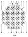
- the supervision of a particularly preferred embodiment of a particularly preferred light source 2 in FIG. 2shows carrier material fields 9, on which light-emitting diodes 10, 11, 12 are arranged in the form of chip pads and are electrically conductively connected to the carrier material fields 9.
- the Carrier material fields 9are direct current from those adjacent to them Carrier material springs 9 separated by trenches 13 and in the form of a matrix arranged.
- the LEDs with the reference number 10are red, with the Reference numerals 11 are blue and reference numerals 12 are green.
- Several light emitting diodes 10, 11, 12 each of one colorare of such a type connected in series that a bond wire 15 with either the LED chip pad 10, 11, 12 or is connected to the carrier field 9.
- the respective Row endis led to external connections R, G, B, the external connection R with red LEDs, the external connection G with green ones Light-emitting diodes and the external connection B are connected to blue light-emitting diodes is.
- the relative high number of green LEDs 12 compared to the red ones and blue LEDs 10, 11is due to the fact that the human eye Mixed light then feels white when the light makes you feel special high proportion of green light versus low proportions of has red and blue light.
- the arrangement of the light-emitting diodes 10, 11, 12forms almost a circular area. LEDs outside this circular area would only increase energy consumption and heat generation, without significantly improving the light output when the light is through the condenser lens 7 shown in Figure 1 is sent.
- a circle that can completely enclose the circular areafor example one Have a diameter of six millimeters.
- the edge lengths of the carrier fields 9are approximately 600 ⁇ m, the red LED chip pads 10 approx. 250 ⁇ m and the blue and green ones LED chip pads 11, 12 each approx. 310 ⁇ m.
- the edge lengths of the carrier fields 9are approximately 600 ⁇ m, the red LED chip pads 10 approx. 250 ⁇ m and the blue and green ones LED chip pads 11, 12 each approx. 310 ⁇ m.
- the light source 2achieves the required luminance.
- the LEDs 10, 11, 12 in the form of chip padswhich are electrical conductively connected to metallic carrier material fields 9 and on these are arranged.
- the carrier material fields 9are on a thermally conductive electrical insulation layer 16 arranged.
- Under the insulation layer 16is still another heat-conducting electrical Insulation layer 17, for example made of silicon or ceramic, which is thermally conductive is connected to a copper support 19, for example with a conductive adhesive or a solder layer 18.
- the copper carrier 19is used at the same time the uniform heat distribution in the light source 2 and with it also the cooling.
- the carrier 19can also be good from another manufactured heat-conducting material and / or connected to a heat sink his.
- the light source 2can also be cooled by a fan, for example or be realized by a Peltier element.
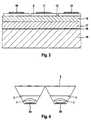
- Figure 4there are two light sources 2, each via a condenser lens 7 each shine through a display 3.
- This arrangementis particularly useful if the height and width of each desired display field 5 differ greatly from one another. That's how it is Light of the existing light emitting diodes is better used. Keep kicking fewer problems due to distortion or suppression distortion is easier to realize. It is also possible to use several Light sources 2 to shine through a single display 3.
Landscapes
- Physics & Mathematics (AREA)
- Engineering & Computer Science (AREA)
- Chemical & Material Sciences (AREA)
- General Physics & Mathematics (AREA)
- Mechanical Engineering (AREA)
- Transportation (AREA)
- Nonlinear Science (AREA)
- Combustion & Propulsion (AREA)
- Optics & Photonics (AREA)
- Mathematical Physics (AREA)
- Crystallography & Structural Chemistry (AREA)
- Led Device Packages (AREA)
- Instrument Panels (AREA)
- Devices For Indicating Variable Information By Combining Individual Elements (AREA)
- Liquid Crystal (AREA)
Abstract
Description
Translated fromGermanDie Erfindung betrifft ein Farb-Head-up Display, insbesondere für einFahrzeug.The invention relates to a color head-up display, in particular for aVehicle.
Aus dem Stand der Technik sind Farb-Head-up Displays mit den verschiedenartigstenLichtquellen bekannt, wie beispielsweise Leuchtstofflampenoder Halogenlampen bekannt, bei denen das Licht der Lichtquelledurch eine zumindest teilweise Licht durchlässige Anzeige gesendetwird und auf eine Scheibe projezierbar ist. Halogenlampen haben denNachteil der relativ kurzen Haltbarkeit (ca. 500 - 1000 Betriebsstunden).Durch die Einbaulage bei Head-up Displays in Kraftfahrzeugen ist einWechsel der Lampen nur durch geschultes Fachpersonal möglich. BeiLeuchtstofflampen kann nur ein geringer Teil der Lichtenergie für die Beleuchtungwegen der geometrischen Abmessungen der Leuchtstofflampeund dem kleinen nutzbaren Bereich für eine Head-up Display Optik verwendetwerden.Color head-up displays with the most varied are from the prior artLight sources known, such as fluorescent lampsor halogen lamps in which the light of the light source is knownsent by an at least partially translucent displayand can be projected onto a pane. Halogen lamps have thatDisadvantage of the relatively short shelf life (approx. 500 - 1000 operating hours).Due to the installation position in head-up displays in motor vehicles is aThe lamps can only be changed by trained specialist personnel. AtFluorescent lamps can only use a small part of the light energy for lightingbecause of the geometric dimensions of the fluorescent lampand the small usable area for head-up display opticsbecome.
Weiterhin ist bei Kraftfahrzeug Head-up Displays ein großer Dimmbereichder Lichtquelle erforderlich, da die Umgebungshelligkeit um das Kraftfahrzeugje nach Tageszeit und Umgebung sich stark verändert. Da sich beiDimmung von Halogen- und Leuchtstofflampen deren spektrale Eigenschaften verändern, ist eine farbneutrale Dimmung höchstens unter hohembaulichen Aufwand mit entsprechendem Platzbedarf möglich.Furthermore, there is a large dimming range for motor vehicle head-up displaysthe light source is required because of the ambient brightness around the motor vehiclechanges significantly depending on the time of day and the environment. Because atDimming of halogen and fluorescent lamps their spectral propertieschange, color-neutral dimming is at most under highconstruction effort possible with corresponding space requirement.
Aufgabe der Erfindung ist es daher, ein Farb-Head-up Display anzugeben,das kompakt aufgebaut ist und das in einem weiten Bereich dimmbar ist.The object of the invention is therefore to provide a color head-up display,that is compact and that is dimmable in a wide range.
Diese Aufgabe wird dadurch gelöst, daß eine Vielzahl von roten, grünenund blauen Leuchtdioden ohne Verpackung auf einem gemeinsamen Trägerangeordnet sind und das eine Wärmeabfuhrvorrichtung zum Kühlender Leuchtdioden vorhanden ist. Durch den Verzicht auf die sonst üblicheVerpackung (Gehäuse der Leuchtdioden) können die einzelnen Leuchtdiodensehr dicht nebeneinander angeordnet werden. Dadurch wird einehohe Leuchtdichte erreicht, die zum Durchleuchten der Anzeige benötigtwird, um auch bei hellen Tageslichtverhältnissen eine optimale optischeDarstellung zu erzielen. Die Kühleinrichtung schützt dann die sehr dichtnebeneinanderliegend angeordneten Leuchtdioden vor einer thermischenÜberlastung.This object is achieved in that a large number of red, greenand blue LEDs without packaging on a common carrierare arranged and a heat dissipation device for coolingthe LEDs are present. By doing without the usualPackaging (housing of the light emitting diodes) can the individual light emitting diodesbe arranged very close to each other. This will make oneachieved high luminance, which is required to illuminate the displayis an optimal optical even in bright daylight conditionsTo achieve representation. The cooling device then protects it very tightlyjuxtaposed light emitting diodes in front of a thermalOverload.
Die Vielzahl der Leuchtdioden kann in Form eines kompakten Feldes angeordnetsein. Das kompakte Feld kann beispielsweise als Matrix ausgestaltetsein. Hierdurch kann das Bonden der einzelnen Dioden einfachdurchgeführt werden. Es ist beispielsweise auch möglich, die Anordnungder Dioden spiralförmig oder in Form ineinanderliegender konzentrischerKreise auszugestalten.The large number of light-emitting diodes can be arranged in the form of a compact fieldhis. The compact field can be configured, for example, as a matrixhis. This makes it easy to bond the individual diodesbe performed. It is also possible, for example, the arrangementof the diodes spiral or in the form of interlocking concentricDesign circles.
Dadurch, daß die Anzahl der Leuchtdioden einer Farbe an die spektraleEmpfindlichkeit des Auges und den spektralen Wirkungsgrad der Diodenangepaßt sind, können die einzelnen Leuchtdioden bei voller gewünschterLeuchtstärke in einem bestimmten Farbton, insbesondere bei weissemLicht voll ausgenutzt werden, da die verschiedenen Farben dann bei einem Betrachter in etwa das gleiche Helligkeitsempfinden hervorrufen undeine Dimmung einer oder mehrerer Farbgruppen nicht oder nur kaum erforderlichist, um den gewünschten Farbton (insbesondere bei gewünschtemweissen Licht) zu erhalten.The fact that the number of light emitting diodes of a color to the spectralEye sensitivity and the spectral efficiency of the diodesare adjusted, the individual LEDs can be fully desiredLuminosity in a certain color, especially with whiteLight can be fully used, because the different colors are then oneEvoke viewers in roughly the same sense of brightness anda dimming of one or more color groups is not necessary or only rarelyis to the desired color (especially if you wantwhite light).
Dadurch, daß das kompakte Feld weitgehend eine runde Form aufweist,kann die Lichtstärke der vorhandenen Leuchtdioden voll ausgenutzt werden,wenn das Licht durch eine Linsenoptik gesendet wird. So wird Materialund insbesondere Energie eingespart und damit auch die Wärmeentwicklungdurch die Leuchtdioden auf das notwendige Maß reduziert.Because the compact field has a largely round shape,the light intensity of the existing light emitting diodes can be fully used,when the light is sent through lens optics. This is how material becomesand in particular saved energy and thus also the heat developmentreduced to the necessary level by the LEDs.
Besonders einfach ist die Ausgestaltung des kompakten Feldes, wenn dieLeuchtdioden als Chippads ausgestaltet sind, die jeweils auf einem metallischenTrägermaterialfeld aufgebracht sind und ein Anschluß der Leuchtdiodemit diesem elektrisch leitend verbunden ist. Die Leuchtdiode läßtsich im vorbeschriebenen Fall besonders einfach mit elektrischer Energieversorgen, wenn jeweils ein Bond-Draht mit der Leuchtdiode und ein weiterermit dem metallischen Trägermaterialfeld verbunden ist. Durch dieseAusgestaltung ist eine einfache Reihenschaltung mehrerer Leuchtdiodenrealisierbar, wenn die gleichzeitig die Trägermaterialfelder benachbarterDioden gegeneinander elektrisch isoliert sind.The design of the compact field is particularly simple if theLEDs are designed as chip pads, each on a metallicCarrier material field are applied and a connection of the light emitting diodeis electrically connected to this. The LED leavesin the above-described case is particularly easy with electrical energysupply, if one bond wire each with the light emitting diode and anotheris connected to the metallic carrier material field. Through thisDesign is a simple series connection of several light emitting diodesfeasible if the carrier material fields are adjacent at the same timeDiodes are electrically isolated from each other.
Dadurch, daß mehrere Leuchtdioden in Reihe geschaltet sind, benötigtder integrierte Schaltkreis weniger externe Anschlüsse. Außerdem wirddie Gefahr von Hitze-Spots einzelner Leuchtdioden stark reduziert.Because several LEDs are connected in seriesthe integrated circuit fewer external connections. Besides, willgreatly reduces the risk of heat spots on individual LEDs.
Dadurch, daß mehrere Leuchtdioden einer Farbe in Reihe geschaltet sind,sind die verschiedenen Farben unterschiedlich dimmbar und so unterschiedlicheFarben darstellbar bei gleichzeitig wenig benötigten externenAnschlüssen.Because several light emitting diodes of one color are connected in series,the different colors are differently dimmable and so differentColors can be displayed with little external needConnections.
Durch Verwendung eines Farb-Flüssigkristalldisplays als lichtdurchlässigeAnzeige in den vorgenannten Head-up Displays ist eine einfacheFarbdarstellung möglich, insbesondere dann, wenn bei der Lichtquelle dieverschiedenfarbigen Leuchtdioden so angesteuert werden, daß die Lichtquelleweisses Licht aussendet.By using a color liquid crystal display as translucentDisplay in the aforementioned head-up displays is a simple oneColor display possible, especially if the light sourcedifferent colored LEDs are controlled so that the light sourceemits white light.
Die Verwendung eines monochromen Flüssigkristalldisplays als lichtdurchlässigeAnzeige in einem Head-up Display mit der vorbeschriebenenLichtquelle erfordert nur ein einfaches Flüssigkristalldisplay und erlaubtdennoch eine Farbdarstellung, wenn die einzelnen Farben der Leuchtdiodenin schneller Folge nacheinander ein- und ausschaltbar sind undder Betrachter infolge der Trägheit seiner Augen ein zusammengesetztesBild wahrnimmt.The use of a monochrome liquid crystal display as translucentDisplay in a head-up display with the aboveLight source requires only a simple liquid crystal display and allowsnevertheless a color representation if the individual colors of the light emitting diodescan be switched on and off in quick succession andthe viewer a composite due to the sluggishness of his eyesPerceives image.
Die Erfindung wird nachfolgend anhand der Figuren näher erläutert. Eszeigen:
- Figur 1:
- ein Ausführungsbeispiel eines erfindungsgemäßen Head-upDisplays in einem Kraftfahrzeug
- Figur 2:
- die Aufsicht auf ein besonders bevorzugtes Beispiel einererfindungsgemäßen Lichtquelle
- Figur 3:
- einen Teilschnitt eines besonders bevorzugten Beispiels einererfindungsgemäßen Lichtquelle
- Figur 4:
- die Darstellung eines Head-up Displays mit einer geteiltenLichtquelle
- Figure 1:
- an embodiment of a head-up display according to the invention in a motor vehicle
- Figure 2:
- the supervision of a particularly preferred example of a light source according to the invention
- Figure 3:
- a partial section of a particularly preferred example of a light source according to the invention
- Figure 4:
- the representation of a head-up display with a split light source
Figur 1 zeigt eine Prinzipdarstellung einer teilweise geschnittenen Seitenansichteines in ein Kraftfahrzeug 1 eingesetzten Head-up Displays. DiesesHead-up Display besteht aus einer Lichtquelle 2, einer Kondensorlinse7, einem Flüssigkristalldisplay 3, einer Linsenoptik 4 und einem Projektionsbereich5 auf einer Frontscheibe 6 des Kraftfahrzeugs 1. Die Kondensorlinse7 bewirkt, daß möglichst viel Licht der Lichtquelle 2 zum Flüssigkristalldisplay3 gelangt. Einen guten Lichtausnutzungsgrad kann manz. B. auch dadurch erreichen, daß die Lichtquelle 2 so in einem Hohlspiegelangeordnet wird, daß nahezu alle von der Lichtquelle 2 ausgesandtenLichtstrahlen direkt oder durch Reflexion in Richtung des Flüssigkristalldisplays3 gelangen. Das Flüssigkristalldisplay 3 ist beispielsweise alsPunkt-Matrix ausgestaltet, auf dem im Beispiel ein Pfeil dargestellt ist. DasLicht der Lichtquelle 2 wird von der Kondensorlinse 7 gebündelt, durchdringtdas Flüssigkristalldisplay 3 und wird durch die Linsenoptik 4 auf denProjektionsbereich 5 der Frontscheibe 6 projiziert. Ein Fahrer F des Kraftfahrzeugs1 kann so einen Pfeil 8 mit der übrigen (nicht dargestellten)Umwelt vor dem Fahrzeug wahrnehmen. Je nach Anordnung der Lichtquelle2, der Anzeige 3, des Projektionsbereichs 5 und eventuell der Kondensorlinse7 oder des nicht dargestellten Hohlspiegels kann auch auf dieLinsenoptik 4 verzichtet werden.Figure 1 shows a schematic representation of a partially sectioned side viewof a head-up display used in a motor vehicle 1. ThisHead-up display consists of a
Die Aufsicht auf ein besonders bevorzugtes Ausführungsbeispiel einerbesonders bevorzugten Lichtquelle 2 in Figur 2 zeigt Trägermaterialfelder9, auf denen Leuchtdioden 10, 11, 12 in Form von Chippads angeordnetund mit den Trägermaterialfeldern 9 elektrisch leitend verbunden sind. DieTrägermaterialfelder 9 sind gleichstrommäßig von den ihnen benachbartenTrägermaterialfedern 9 durch Gräben 13 getrennt und matrixförmigangeordnet. Die Leuchtdioden mit den Bezugszeichen 10 sind rot, mit denBezugszeichen 11 sind blau und mit den Bezugszeichen 12 sind grün.Jeweils mehrere Leuchtdioden 10, 11, 12 jeweils einer Farbe sind derartin Reihe geschaltet, daß ein Bond-Draht 15 entweder mit dem LED Chippad 10, 11, 12 oder mit dem Trägerfeld 9 verbunden ist. Hierbei sind immermehrere Leuchtdioden einer Farbe in Reihe geschaltet. Das jeweiligeReihenende ist an Außenanschlüsse R, G, B geführt, wobei der AußenanschlußR mit roten Leuchtdioden, der Außenanschluß G mit grünenLeuchtdioden und der Außenanschluß B mit blauen Leuchtdioden verbundenist. Man kann durch ein Nachfahren der Bond-Drähte beginnendan den Außenanschlüssen R, G, B erkennen, daß sich unter den dargestellten69 Leuchtdioden 10, 11, 12, 19 rote Leuchtdioden 10, 16 blaueLeuchtdioden 11 und 34 grüne Leuchtdioden 12 befinden. Die verhältnismäßighohe Anzahl von grünen Leuchtdioden 12 gegenüber den rotenund blauen Leuchtdioden 10, 11 liegt daran, daß das menschliche Augegemischtes Licht dann als weiss empfindet, wenn das Licht einen besondershohen Anteil von grünem Licht gegenüber niedrigen Anteilen vonrotem und blauem Licht aufweist.The supervision of a particularly preferred embodiment of aparticularly preferred
Man erkennt weiterhin, daß die Anordnung der Leuchtdioden 10, 11, 12nahezu eine Kreisfläche bildet. Leuchtdioden außerhalb dieser Kreisflächewürden nur den Energieverbrauch und die Wärmeentwicklung vergrößern,ohne wesentlich die Lichtausbeute zu verbessern, wenn das Licht durchdie in Figur 1 dargestellte Kondensorlinse 7 gesendet wird. Ein Kreis, derdie Kreisläche vollständig umschliessen kann, kann beispielsweise einenDurchmesser von sechs Millimetern aufweisen. Bei dem dargestelltenBeispiel betragen die Kantenlängen der Trägerfelder 9 ca. 600µm, derroten Leuchtdiodenchippads 10 ca. 250 µm und der blauen und grünenLeuchtdiodenchippads 11,12 jeweils ca. 310µm. Es sind jedoch auch andereAbmessungen vorstellbar. Durch den geringen Durchmesser derKreisfläche und die hohe Anzahl von Leuchtdioden (im vorstehenden Beispiel69 Stück) erzielt die Lichtquelle 2 die erforderliche Leuchtdichte. DieAusgestaltung der Kreisfläche könnte man auch beispielsweise dadurchrealisieren, daß man die nebeneinanderliegenden Dioden in Form ineinanderliegenderkonzentrischer Kreise oder einer Spirale anordnet.It can also be seen that the arrangement of the light-emitting
Bei dem in Figur 3 dargestellten Teilschnitt durch eine Lichtquelle 2 erkenntman die Leuchtdioden 10, 11, 12 in Form von Chippads, die elektrischleitend mit metallischen Trägermaterialfeldern 9 verbunden und aufdiesen angeordnet sind. Die Trägermaterialfelder 9 sind auf einer wärmeleitendenelektrischen Isolationsschicht 16 angeordnet. Unter der Isolationsschicht16 befindet sich noch eine weitere wärmeleitende elektrischeIsolationsschicht 17, beispielsweise aus Silicium oder Keramik, die wärmeleitendmit einem Kupferträger 19 verbunden ist, beispielsweise miteinem Leitkleber oder einer Lötschicht 18. Der Kupferträger 19 dientgleichzeitig der gleichmäßigen Wärmeverteilung in der Lichtquelle 2 unddamit auch der Kühlung. Der Träger 19 kann auch aus einem anderen gutwärmeleitenden Material hergestellt und/oder mit einem Kühlkörper verbundensein.In the partial section through a
Eine Kühlung der Lichtquelle 2 kann beispielsweise auch durch ein Gebläseoder durch ein Peltier-Element realisiert sein.The
In Figur 4 sind zwei Lichtquellen 2 vorhanden, die jeweils über eine Kondensorlinse7 jeweils eine Anzeige 3 durchstrahlen. Diese Anordnung istinsbesondere dann sinnvoll, wenn die Höhe und die Breite des jeweilsgewünschten Anzeigefeldes 5 stark voneinander abweichen. So wird dasLicht der vorhandenen Leuchtdioden besser ausgenutzt. Weiterhin tretenweniger Probleme infolge von Verzerrungen auf bzw. eine Unterdrückungvon Verzerrungen ist leichter realisierbar. Auch ist es möglich, mit mehrerenLichtquellen 2 eine einzige Anzeige 3 zu durchstrahlen.In Figure 4 there are two
Claims (15)
Translated fromGermanApplications Claiming Priority (2)
| Application Number | Priority Date | Filing Date | Title |
|---|---|---|---|
| DE10016817ADE10016817A1 (en) | 2000-04-05 | 2000-04-05 | Color head-up display, especially for a vehicle |
| DE10016817 | 2000-04-05 |
Publications (1)
| Publication Number | Publication Date |
|---|---|
| EP1143288A1true EP1143288A1 (en) | 2001-10-10 |
Family
ID=7637607
Family Applications (1)
| Application Number | Title | Priority Date | Filing Date |
|---|---|---|---|
| EP01101777AWithdrawnEP1143288A1 (en) | 2000-04-05 | 2001-01-26 | Colour head up display, in particular for vehicle |
Country Status (4)
| Country | Link |
|---|---|
| US (1) | US7034778B1 (en) |
| EP (1) | EP1143288A1 (en) |
| JP (1) | JP2001356294A (en) |
| DE (1) | DE10016817A1 (en) |
Cited By (9)
| Publication number | Priority date | Publication date | Assignee | Title |
|---|---|---|---|---|
| EP1580588A1 (en) | 2004-03-25 | 2005-09-28 | Robert Bosch Gmbh | Device for visual presentation of informations |
| WO2006019085A1 (en) | 2004-08-18 | 2006-02-23 | Sony Corporation | Heat-dissipating device and display |
| DE10245580B4 (en)* | 2002-09-27 | 2006-06-01 | Siemens Ag | Device for generating an image |
| EP1903380A1 (en)* | 2006-09-20 | 2008-03-26 | Everlight Electronics Co., Ltd. | Arrangement matrix of primary color LEDs |
| US7616184B2 (en) | 2006-06-28 | 2009-11-10 | Everlight Electronics Co., Ltd. | Arrangement matrix of primary color LEDs |
| DE102008023225A1 (en) | 2008-05-10 | 2009-11-12 | Bayerische Motoren Werke Aktiengesellschaft | Head-up display for vehicle, has image formation device for forming image and optical system for mapping image, particularly on windshield of vehicle, where adjusting device is provided for adjusting mapping device |
| DE102009011908A1 (en) | 2009-03-05 | 2010-09-09 | Bayerische Motoren Werke Aktiengesellschaft | Head-up display and vehicle |
| EP1840626B1 (en)* | 2006-03-29 | 2016-05-11 | GM Global Technology Operations LLC | Head-up display, motor vehicle und method for operating a head-up display |
| CN107390366A (en)* | 2017-08-30 | 2017-11-24 | 厦门天马微电子有限公司 | A kind of display system, display methods and the vehicles |
Families Citing this family (49)
| Publication number | Priority date | Publication date | Assignee | Title |
|---|---|---|---|---|
| KR20040019453A (en)* | 2002-08-26 | 2004-03-06 | 현대자동차주식회사 | Device for adjusting color and brightness HUD system, and process of preparing the same |
| DE10245892A1 (en)* | 2002-09-30 | 2004-05-13 | Siemens Ag | Illumination device for backlighting an image display device |
| US7310071B2 (en)* | 2002-10-18 | 2007-12-18 | Kopin Corporation | Instrument panel with active display |
| JP4776898B2 (en)* | 2003-08-01 | 2011-09-21 | 株式会社半導体エネルギー研究所 | vehicle |
| US7772756B2 (en)* | 2003-08-01 | 2010-08-10 | Semiconductor Energy Laboratory Co., Ltd. | Light-emitting device including a dual emission panel |
| JP2008535233A (en)* | 2005-03-30 | 2008-08-28 | コーニンクレッカ フィリップス エレクトロニクス エヌ ヴィ | Flexible LED array |
| DE102005017206A1 (en)* | 2005-04-14 | 2006-10-19 | Carl Zeiss Jena Gmbh | LED module for head up display of vehicle, has color LED, which sends spectral centroid and is arranged in direct proximity to white light LED, where symmetry in terms of axis or point is produced between each white light LED and color LED |
| DE102005019621B4 (en)* | 2005-04-26 | 2013-05-23 | Johnson Controls Automotive Electronics Gmbh | Display device for a motor vehicle and use of an arrangement of light-emitting components |
| DE102005059416A1 (en)* | 2005-12-13 | 2007-06-14 | Bayerische Motoren Werke Ag | Head-up display for vehicle, has light source with light emitting diodes that emit white light, and conversion device that is formed such that ultra violet part of white light is partially converted into red and/or green light |
| DE102006005571A1 (en)* | 2006-02-06 | 2007-08-09 | Siemens Ag | Head-Up Display |
| DE102006019731A1 (en)* | 2006-04-28 | 2007-10-31 | Bayerische Motoren Werke Ag | Head-up-display e.g. liquid crystal display, for use in vehicle, has light source with light emitting diode, and conversion device designed so that green light, which is emitted from diode is partially converted into red light |
| US20080068565A1 (en)* | 2006-09-12 | 2008-03-20 | Ods Co., Ltd. | Micro display device |
| EP1918769B1 (en) | 2006-10-27 | 2013-02-13 | Samsung Electronics Co., Ltd. | Backlight unit and liquid crystal display device including the same |
| JP5334813B2 (en)* | 2009-11-25 | 2013-11-06 | 株式会社沖データ | Light emitting element array and image display device |
| DE102010001893A1 (en)* | 2010-02-12 | 2011-08-18 | Osram Gesellschaft mit beschränkter Haftung, 81543 | Substrate for a light module and light module |
| JP5683690B2 (en)* | 2010-05-26 | 2015-03-11 | ジョンソン・コントロールズ・ゲー・エム・ベー・ハー | Displays, especially vehicle head-up displays |
| US7982959B1 (en)* | 2010-08-02 | 2011-07-19 | Matvey Lvovskiy | Head-up display |
| US8564000B2 (en) | 2010-11-22 | 2013-10-22 | Cree, Inc. | Light emitting devices for light emitting diodes (LEDs) |
| US8575639B2 (en) | 2011-02-16 | 2013-11-05 | Cree, Inc. | Light emitting devices for light emitting diodes (LEDs) |
| US9490235B2 (en) | 2010-11-22 | 2016-11-08 | Cree, Inc. | Light emitting devices, systems, and methods |
| US9300062B2 (en) | 2010-11-22 | 2016-03-29 | Cree, Inc. | Attachment devices and methods for light emitting devices |
| US9000470B2 (en) | 2010-11-22 | 2015-04-07 | Cree, Inc. | Light emitter devices |
| US8624271B2 (en) | 2010-11-22 | 2014-01-07 | Cree, Inc. | Light emitting devices |
| US8455908B2 (en) | 2011-02-16 | 2013-06-04 | Cree, Inc. | Light emitting devices |
| USD702653S1 (en) | 2011-10-26 | 2014-04-15 | Cree, Inc. | Light emitting device component |
| US8878660B2 (en) | 2011-06-28 | 2014-11-04 | Nissan North America, Inc. | Vehicle meter cluster |
| FR2979081A1 (en)* | 2011-08-18 | 2013-02-22 | Johnson Contr Automotive Elect | DISPLAY DEVICE, IN PARTICULAR FOR A MOTOR VEHICLE |
| DE102011121558B4 (en)* | 2011-10-05 | 2017-06-01 | Johnson Controls Automotive Electronics Gmbh | Display device and method for operating a display device |
| KR20140097284A (en) | 2011-11-07 | 2014-08-06 | 크리,인코포레이티드 | High voltage array light emitting diode(led) devices, fixtures and methods |
| US8477401B1 (en)* | 2011-12-08 | 2013-07-02 | Delphi Technologies, Inc. | Windshield with fluorescent electrowetting display |
| US9372343B2 (en)* | 2012-01-12 | 2016-06-21 | Htc Corporation | Head-up display, vehicle and controlling method of head-up display |
| US10134961B2 (en) | 2012-03-30 | 2018-11-20 | Cree, Inc. | Submount based surface mount device (SMD) light emitter components and methods |
| US10222032B2 (en) | 2012-03-30 | 2019-03-05 | Cree, Inc. | Light emitter components and methods having improved electrical contacts |
| US9735198B2 (en) | 2012-03-30 | 2017-08-15 | Cree, Inc. | Substrate based light emitter devices, components, and related methods |
| USD740453S1 (en) | 2013-06-27 | 2015-10-06 | Cree, Inc. | Light emitter unit |
| USD739565S1 (en) | 2013-06-27 | 2015-09-22 | Cree, Inc. | Light emitter unit |
| JP6277698B2 (en)* | 2013-12-10 | 2018-02-14 | 株式会社デンソー | Projector for vehicle |
| DE102014003351B4 (en)* | 2014-03-07 | 2022-11-03 | Dioptic Gmbh | Head-up display and display method |
| FR3018929B1 (en)* | 2014-03-21 | 2017-07-07 | Thales Sa | VISUALIZATION DEVICE COMPRISING A VARIABLE REFLECTION RATE COMBINER |
| CN104777646B (en)* | 2015-04-15 | 2018-08-17 | 重庆交通大学 | A kind of interior multimedia video system being shown in windshield |
| WO2017051655A1 (en)* | 2015-09-25 | 2017-03-30 | 富士フイルム株式会社 | Projection type display device and projection control method |
| JP6046228B2 (en)* | 2015-10-15 | 2016-12-14 | シャープ株式会社 | Light emitting device |
| USD823492S1 (en) | 2016-10-04 | 2018-07-17 | Cree, Inc. | Light emitting device |
| EP3451044A1 (en) | 2017-08-28 | 2019-03-06 | Continental Automotive GmbH | Head-up display and method for driving a head-up display |
| WO2019065613A1 (en)* | 2017-09-27 | 2019-04-04 | 日本精機株式会社 | Head-up display |
| US11474351B2 (en)* | 2018-05-23 | 2022-10-18 | Nippon Seiki Co., Ltd. | Head-up display device |
| JP7087981B2 (en)* | 2018-12-18 | 2022-06-21 | 株式会社デンソー | Virtual image display device |
| CN114245887B (en) | 2019-07-15 | 2024-11-29 | 上海延锋金桥汽车饰件系统有限公司 | Vehicle interior component |
| DE102021202388A1 (en) | 2021-03-11 | 2022-09-15 | Continental Automotive Technologies GmbH | Lighting device with heat sink |
Citations (8)
| Publication number | Priority date | Publication date | Assignee | Title |
|---|---|---|---|---|
| US3867633A (en)* | 1971-12-17 | 1975-02-18 | Texas Instruments Inc | Wide angle viewing system for limited visibility conditions |
| DE3844701A1 (en)* | 1988-10-19 | 1991-04-04 | Messerschmitt Boelkow Blohm | Display screen - uses combination of LED and LCD devices for matrix display panel |
| WO1991009477A1 (en)* | 1989-12-14 | 1991-06-27 | Bicc Network Solutions, Inc. | Free space local area network system |
| US5198812A (en)* | 1992-03-04 | 1993-03-30 | The United States Of America As Represented By The Secretary Of The Air Force | Aircraft attitude indicator display |
| US5200844A (en)* | 1992-05-22 | 1993-04-06 | Kaiser Aerospace & Electronics Corporation | Color head-up display system |
| DE19540108A1 (en) | 1995-10-27 | 1997-04-30 | Ldt Gmbh & Co | Device for displaying a first image in a second image visible through a transparent pane |
| US5864387A (en) | 1996-12-18 | 1999-01-26 | Creative Products Unlimited, Inc. | Method and apparatus for creating in-line index prints |
| US6044180A (en)* | 1990-04-20 | 2000-03-28 | Nec Corporation | Method and apparatus for rapid scanning of color images |
Family Cites Families (31)
| Publication number | Priority date | Publication date | Assignee | Title |
|---|---|---|---|---|
| JPS556687A (en)* | 1978-06-29 | 1980-01-18 | Handotai Kenkyu Shinkokai | Traffic use display |
| FR2584843B1 (en)* | 1985-07-12 | 1989-02-24 | Sfena | EXTENDED FIELD VIEWING APPARATUS IN WHICH THE IMAGE IS FORMED BY THE JUXTAPOSITION OF AT LEAST TWO PARTIAL IMAGES |
| JPS6486573A (en)* | 1987-07-17 | 1989-03-31 | Oshima Denki Co | Light emitting device |
| US5013135A (en)* | 1989-07-10 | 1991-05-07 | Matsushita Electric Industrial Co., Ltd. | Head-up display with two fresnel lenses |
| US5805119A (en)* | 1992-10-13 | 1998-09-08 | General Motors Corporation | Vehicle projected display using deformable mirror device |
| US5557353A (en)* | 1994-04-22 | 1996-09-17 | Stahl; Thomas D. | Pixel compensated electro-optical display system |
| EP0724174A4 (en)* | 1994-07-15 | 1998-12-09 | Matsushita Electric Industrial Co Ltd | 'HEADUP' DISPLAY DEVICE, LIQUID CRYSTAL DISPLAY PANEL AND PRODUCTION METHOD THEREFOR |
| US5710668A (en)* | 1995-05-26 | 1998-01-20 | Flight Dynamics | Multi-color head-up display system |
| US5657163A (en)* | 1995-05-31 | 1997-08-12 | Delco Electronics Corporation | Fiber optic illumination of HUD image source |
| JP3778597B2 (en)* | 1995-10-18 | 2006-05-24 | 日亜化学工業株式会社 | LED chip die bonding method |
| JPH09146089A (en)* | 1995-11-28 | 1997-06-06 | Masahiko Yamamoto | Surface light source for color display device and liquid crystal display device |
| JP3613867B2 (en)* | 1995-12-28 | 2005-01-26 | 株式会社島津製作所 | Display device |
| EP0818701B1 (en)* | 1996-07-09 | 2002-10-02 | Harness System Technologies Research, Ltd. | Display device |
| JPH1035324A (en)* | 1996-07-23 | 1998-02-10 | Toyoda Gosei Co Ltd | Head-up display device |
| JP3687763B2 (en)* | 1996-08-02 | 2005-08-24 | 株式会社シチズン電子 | Color display device |
| JP4007633B2 (en)* | 1996-10-09 | 2007-11-14 | 株式会社島津製作所 | Head up display |
| US5909182A (en)* | 1996-12-02 | 1999-06-01 | Alstom Signaling Inc. | Vandal resistant light signal unit |
| JPH10319871A (en)* | 1997-05-19 | 1998-12-04 | Kouha:Kk | LED display device |
| US6292305B1 (en)* | 1997-08-25 | 2001-09-18 | Ricoh Company, Ltd. | Virtual screen display device |
| JPH1167448A (en)* | 1997-08-26 | 1999-03-09 | Toyota Central Res & Dev Lab Inc | Display device |
| US6211626B1 (en)* | 1997-08-26 | 2001-04-03 | Color Kinetics, Incorporated | Illumination components |
| US6909419B2 (en)* | 1997-10-31 | 2005-06-21 | Kopin Corporation | Portable microdisplay system |
| GB2331625B (en)* | 1997-11-19 | 2003-02-26 | Hassan Paddy Abdel Salam | led Lamp |
| CH689339A5 (en) | 1998-02-12 | 1999-02-26 | Staufert Gerhard | LED illumination panel |
| JPH11249582A (en)* | 1998-03-02 | 1999-09-17 | Ricoh Co Ltd | Image display device |
| JPH11338366A (en)* | 1998-05-21 | 1999-12-10 | Denso Corp | On-vehicle use head-up display |
| JP2000031546A (en)* | 1998-07-08 | 2000-01-28 | Mitsubishi Electric Corp | LED assembly module |
| US6325524B1 (en)* | 1999-01-29 | 2001-12-04 | Agilent Technologies, Inc. | Solid state based illumination source for a projection display |
| US6502956B1 (en)* | 1999-03-25 | 2003-01-07 | Leotek Electronics Corporation | Light emitting diode lamp with individual LED lenses |
| US6111701A (en)* | 1999-07-14 | 2000-08-29 | Rockwell Collins, Inc. | Chromatic aberration corrected multi-color head-up display system |
| US6359737B1 (en)* | 2000-07-28 | 2002-03-19 | Generals Motors Corporation | Combined head-up display |
- 2000
- 2000-04-05DEDE10016817Apatent/DE10016817A1/ennot_activeWithdrawn
- 2000-07-31USUS09/628,922patent/US7034778B1/ennot_activeExpired - Fee Related
- 2001
- 2001-01-26EPEP01101777Apatent/EP1143288A1/ennot_activeWithdrawn
- 2001-04-04JPJP2001106106Apatent/JP2001356294A/enactivePending
Patent Citations (8)
| Publication number | Priority date | Publication date | Assignee | Title |
|---|---|---|---|---|
| US3867633A (en)* | 1971-12-17 | 1975-02-18 | Texas Instruments Inc | Wide angle viewing system for limited visibility conditions |
| DE3844701A1 (en)* | 1988-10-19 | 1991-04-04 | Messerschmitt Boelkow Blohm | Display screen - uses combination of LED and LCD devices for matrix display panel |
| WO1991009477A1 (en)* | 1989-12-14 | 1991-06-27 | Bicc Network Solutions, Inc. | Free space local area network system |
| US6044180A (en)* | 1990-04-20 | 2000-03-28 | Nec Corporation | Method and apparatus for rapid scanning of color images |
| US5198812A (en)* | 1992-03-04 | 1993-03-30 | The United States Of America As Represented By The Secretary Of The Air Force | Aircraft attitude indicator display |
| US5200844A (en)* | 1992-05-22 | 1993-04-06 | Kaiser Aerospace & Electronics Corporation | Color head-up display system |
| DE19540108A1 (en) | 1995-10-27 | 1997-04-30 | Ldt Gmbh & Co | Device for displaying a first image in a second image visible through a transparent pane |
| US5864387A (en) | 1996-12-18 | 1999-01-26 | Creative Products Unlimited, Inc. | Method and apparatus for creating in-line index prints |
Cited By (15)
| Publication number | Priority date | Publication date | Assignee | Title |
|---|---|---|---|---|
| DE10245580B4 (en)* | 2002-09-27 | 2006-06-01 | Siemens Ag | Device for generating an image |
| EP1580588A1 (en) | 2004-03-25 | 2005-09-28 | Robert Bosch Gmbh | Device for visual presentation of informations |
| KR101155696B1 (en)* | 2004-08-18 | 2012-06-12 | 소니 주식회사 | Heat-dissipating device and display |
| WO2006019085A1 (en) | 2004-08-18 | 2006-02-23 | Sony Corporation | Heat-dissipating device and display |
| EP1785764A4 (en)* | 2004-08-18 | 2008-03-26 | Sony Corp | Heat-dissipating device and display |
| US7663730B2 (en) | 2004-08-18 | 2010-02-16 | Sony Corporation | Heat radiator and display unit |
| EP1840626B1 (en)* | 2006-03-29 | 2016-05-11 | GM Global Technology Operations LLC | Head-up display, motor vehicle und method for operating a head-up display |
| US7616184B2 (en) | 2006-06-28 | 2009-11-10 | Everlight Electronics Co., Ltd. | Arrangement matrix of primary color LEDs |
| EP1903380A1 (en)* | 2006-09-20 | 2008-03-26 | Everlight Electronics Co., Ltd. | Arrangement matrix of primary color LEDs |
| DE102008023225A1 (en) | 2008-05-10 | 2009-11-12 | Bayerische Motoren Werke Aktiengesellschaft | Head-up display for vehicle, has image formation device for forming image and optical system for mapping image, particularly on windshield of vehicle, where adjusting device is provided for adjusting mapping device |
| DE102008023225B4 (en) | 2008-05-10 | 2019-08-08 | Bayerische Motoren Werke Aktiengesellschaft | Head-up display and vehicle |
| DE102009011908A1 (en) | 2009-03-05 | 2010-09-09 | Bayerische Motoren Werke Aktiengesellschaft | Head-up display and vehicle |
| US9400386B2 (en) | 2009-03-05 | 2016-07-26 | Bayerische Motoren Werke Aktiengesellschaft | Head-up display having an image-generating device for generating an image and optical system for projecting the image |
| DE102009011908B4 (en) | 2009-03-05 | 2021-12-09 | Bayerische Motoren Werke Aktiengesellschaft | Head-up display and vehicle |
| CN107390366A (en)* | 2017-08-30 | 2017-11-24 | 厦门天马微电子有限公司 | A kind of display system, display methods and the vehicles |
Also Published As
| Publication number | Publication date |
|---|---|
| US7034778B1 (en) | 2006-04-25 |
| DE10016817A1 (en) | 2001-10-18 |
| JP2001356294A (en) | 2001-12-26 |
Similar Documents
| Publication | Publication Date | Title |
|---|---|---|
| EP1143288A1 (en) | Colour head up display, in particular for vehicle | |
| DE10245933B4 (en) | Device for generating a bundled luminous flux | |
| EP1549997B1 (en) | Device for generating an image | |
| DE60125732T2 (en) | LED LIGHT SOURCE WITH OPTICAL VISIBILITY CONTROL SYSTEM | |
| EP1546796B1 (en) | Illumination device for backlighting an image reproduction device | |
| DE102004057499B4 (en) | A method and apparatus for producing uncolored, white light using off-white light emitting diodes | |
| DE102005026949B4 (en) | LED lamp as a light source for a lighting unit | |
| EP1618430B1 (en) | Light source | |
| DE102005031336B4 (en) | projection device | |
| DE102015100631A1 (en) | Light-emitting device, light source for illumination and illumination device | |
| EP1081426A2 (en) | Lighting element comprising a supporting and mounting body, a cover and a light source | |
| DE102005056646A1 (en) | A light-emitting device comprising a plurality of adjacent, overlapping light guide plates | |
| DE102007043903A1 (en) | Luminous device | |
| DE102016111082A1 (en) | Illumination light source, lighting device, exterior lighting device and vehicle headlight | |
| DE19542416A1 (en) | Arrangement for generating a directed light radiation from an LED | |
| EP2534003B1 (en) | Reading light for motor vehicles | |
| DE102009032886A1 (en) | Light-emitting diode component, light-emitting diode module and display device | |
| WO2007090824A1 (en) | Head-up display | |
| DE102017111604A1 (en) | street lamp | |
| DE102014110087A1 (en) | Light emitting module, lighting device and lighting equipment | |
| DE102008017271B4 (en) | Luminaire with two light sources in a recess of an at least partially photoconductive support, use of this lamp as a pendant, wall or floor lamp and lighting device for such a lamp | |
| EP1152186A1 (en) | Illumination device and method for illumination | |
| WO2005091382A1 (en) | Light source for an image-generating unit | |
| DE10344686A1 (en) | Head-Up Display | |
| DE10164033B4 (en) | Optoelectronic component with a plurality of light sources |
Legal Events
| Date | Code | Title | Description |
|---|---|---|---|
| PUAI | Public reference made under article 153(3) epc to a published international application that has entered the european phase | Free format text:ORIGINAL CODE: 0009012 | |
| AK | Designated contracting states | Kind code of ref document:A1 Designated state(s):DE ES FR GB Kind code of ref document:A1 Designated state(s):AT BE CH CY DE DK ES FI FR GB GR IE IT LI LU MC NL PT SE TR | |
| AX | Request for extension of the european patent | Free format text:AL;LT;LV;MK;RO;SI | |
| 17P | Request for examination filed | Effective date:20010907 | |
| RAP1 | Party data changed (applicant data changed or rights of an application transferred) | Owner name:SIEMENS AKTIENGESELLSCHAFT | |
| AKX | Designation fees paid | Free format text:DE ES FR GB | |
| 17Q | First examination report despatched | Effective date:20070301 | |
| RAP1 | Party data changed (applicant data changed or rights of an application transferred) | Owner name:CONTINENTAL AUTOMOTIVE GMBH | |
| APBK | Appeal reference recorded | Free format text:ORIGINAL CODE: EPIDOSNREFNE | |
| APBN | Date of receipt of notice of appeal recorded | Free format text:ORIGINAL CODE: EPIDOSNNOA2E | |
| APBR | Date of receipt of statement of grounds of appeal recorded | Free format text:ORIGINAL CODE: EPIDOSNNOA3E | |
| APAF | Appeal reference modified | Free format text:ORIGINAL CODE: EPIDOSCREFNE | |
| APBT | Appeal procedure closed | Free format text:ORIGINAL CODE: EPIDOSNNOA9E | |
| STAA | Information on the status of an ep patent application or granted ep patent | Free format text:STATUS: THE APPLICATION IS DEEMED TO BE WITHDRAWN | |
| 18D | Application deemed to be withdrawn | Effective date:20140801 |