EP1142748A2 - Power controller for a vehicle - Google Patents
Power controller for a vehicleDownload PDFInfo
- Publication number
- EP1142748A2 EP1142748A2EP01103673AEP01103673AEP1142748A2EP 1142748 A2EP1142748 A2EP 1142748A2EP 01103673 AEP01103673 AEP 01103673AEP 01103673 AEP01103673 AEP 01103673AEP 1142748 A2EP1142748 A2EP 1142748A2
- Authority
- EP
- European Patent Office
- Prior art keywords
- remaining capacity
- battery
- engine
- control portion
- power source
- Prior art date
- Legal status (The legal status is an assumption and is not a legal conclusion. Google has not performed a legal analysis and makes no representation as to the accuracy of the status listed.)
- Withdrawn
Links
Images


Classifications
- H—ELECTRICITY
- H02—GENERATION; CONVERSION OR DISTRIBUTION OF ELECTRIC POWER
- H02J—CIRCUIT ARRANGEMENTS OR SYSTEMS FOR SUPPLYING OR DISTRIBUTING ELECTRIC POWER; SYSTEMS FOR STORING ELECTRIC ENERGY
- H02J9/00—Circuit arrangements for emergency or stand-by power supply, e.g. for emergency lighting
- H02J9/002—Circuit arrangements for emergency or stand-by power supply, e.g. for emergency lighting in which a reserve is maintained in an energy source by disconnecting non-critical loads, e.g. maintaining a reserve of charge in a vehicle battery for starting an engine
- B—PERFORMING OPERATIONS; TRANSPORTING
- B60—VEHICLES IN GENERAL
- B60L—PROPULSION OF ELECTRICALLY-PROPELLED VEHICLES; SUPPLYING ELECTRIC POWER FOR AUXILIARY EQUIPMENT OF ELECTRICALLY-PROPELLED VEHICLES; ELECTRODYNAMIC BRAKE SYSTEMS FOR VEHICLES IN GENERAL; MAGNETIC SUSPENSION OR LEVITATION FOR VEHICLES; MONITORING OPERATING VARIABLES OF ELECTRICALLY-PROPELLED VEHICLES; ELECTRIC SAFETY DEVICES FOR ELECTRICALLY-PROPELLED VEHICLES
- B60L50/00—Electric propulsion with power supplied within the vehicle
- B60L50/10—Electric propulsion with power supplied within the vehicle using propulsion power supplied by engine-driven generators, e.g. generators driven by combustion engines
- B60L50/16—Electric propulsion with power supplied within the vehicle using propulsion power supplied by engine-driven generators, e.g. generators driven by combustion engines with provision for separate direct mechanical propulsion
- B—PERFORMING OPERATIONS; TRANSPORTING
- B60—VEHICLES IN GENERAL
- B60L—PROPULSION OF ELECTRICALLY-PROPELLED VEHICLES; SUPPLYING ELECTRIC POWER FOR AUXILIARY EQUIPMENT OF ELECTRICALLY-PROPELLED VEHICLES; ELECTRODYNAMIC BRAKE SYSTEMS FOR VEHICLES IN GENERAL; MAGNETIC SUSPENSION OR LEVITATION FOR VEHICLES; MONITORING OPERATING VARIABLES OF ELECTRICALLY-PROPELLED VEHICLES; ELECTRIC SAFETY DEVICES FOR ELECTRICALLY-PROPELLED VEHICLES
- B60L58/00—Methods or circuit arrangements for monitoring or controlling batteries or fuel cells, specially adapted for electric vehicles
- B60L58/10—Methods or circuit arrangements for monitoring or controlling batteries or fuel cells, specially adapted for electric vehicles for monitoring or controlling batteries
- B60L58/12—Methods or circuit arrangements for monitoring or controlling batteries or fuel cells, specially adapted for electric vehicles for monitoring or controlling batteries responding to state of charge [SoC]
- B—PERFORMING OPERATIONS; TRANSPORTING
- B60—VEHICLES IN GENERAL
- B60L—PROPULSION OF ELECTRICALLY-PROPELLED VEHICLES; SUPPLYING ELECTRIC POWER FOR AUXILIARY EQUIPMENT OF ELECTRICALLY-PROPELLED VEHICLES; ELECTRODYNAMIC BRAKE SYSTEMS FOR VEHICLES IN GENERAL; MAGNETIC SUSPENSION OR LEVITATION FOR VEHICLES; MONITORING OPERATING VARIABLES OF ELECTRICALLY-PROPELLED VEHICLES; ELECTRIC SAFETY DEVICES FOR ELECTRICALLY-PROPELLED VEHICLES
- B60L58/00—Methods or circuit arrangements for monitoring or controlling batteries or fuel cells, specially adapted for electric vehicles
- B60L58/10—Methods or circuit arrangements for monitoring or controlling batteries or fuel cells, specially adapted for electric vehicles for monitoring or controlling batteries
- B60L58/18—Methods or circuit arrangements for monitoring or controlling batteries or fuel cells, specially adapted for electric vehicles for monitoring or controlling batteries of two or more battery modules
- B60L58/20—Methods or circuit arrangements for monitoring or controlling batteries or fuel cells, specially adapted for electric vehicles for monitoring or controlling batteries of two or more battery modules having different nominal voltages
- B—PERFORMING OPERATIONS; TRANSPORTING
- B60—VEHICLES IN GENERAL
- B60L—PROPULSION OF ELECTRICALLY-PROPELLED VEHICLES; SUPPLYING ELECTRIC POWER FOR AUXILIARY EQUIPMENT OF ELECTRICALLY-PROPELLED VEHICLES; ELECTRODYNAMIC BRAKE SYSTEMS FOR VEHICLES IN GENERAL; MAGNETIC SUSPENSION OR LEVITATION FOR VEHICLES; MONITORING OPERATING VARIABLES OF ELECTRICALLY-PROPELLED VEHICLES; ELECTRIC SAFETY DEVICES FOR ELECTRICALLY-PROPELLED VEHICLES
- B60L2210/00—Converter types
- B60L2210/10—DC to DC converters
- B60L2210/12—Buck converters
- B—PERFORMING OPERATIONS; TRANSPORTING
- B60—VEHICLES IN GENERAL
- B60L—PROPULSION OF ELECTRICALLY-PROPELLED VEHICLES; SUPPLYING ELECTRIC POWER FOR AUXILIARY EQUIPMENT OF ELECTRICALLY-PROPELLED VEHICLES; ELECTRODYNAMIC BRAKE SYSTEMS FOR VEHICLES IN GENERAL; MAGNETIC SUSPENSION OR LEVITATION FOR VEHICLES; MONITORING OPERATING VARIABLES OF ELECTRICALLY-PROPELLED VEHICLES; ELECTRIC SAFETY DEVICES FOR ELECTRICALLY-PROPELLED VEHICLES
- B60L2210/00—Converter types
- B60L2210/40—DC to AC converters
- B—PERFORMING OPERATIONS; TRANSPORTING
- B60—VEHICLES IN GENERAL
- B60L—PROPULSION OF ELECTRICALLY-PROPELLED VEHICLES; SUPPLYING ELECTRIC POWER FOR AUXILIARY EQUIPMENT OF ELECTRICALLY-PROPELLED VEHICLES; ELECTRODYNAMIC BRAKE SYSTEMS FOR VEHICLES IN GENERAL; MAGNETIC SUSPENSION OR LEVITATION FOR VEHICLES; MONITORING OPERATING VARIABLES OF ELECTRICALLY-PROPELLED VEHICLES; ELECTRIC SAFETY DEVICES FOR ELECTRICALLY-PROPELLED VEHICLES
- B60L2240/00—Control parameters of input or output; Target parameters
- B60L2240/40—Drive Train control parameters
- B60L2240/44—Drive Train control parameters related to combustion engines
- B60L2240/441—Speed
- B—PERFORMING OPERATIONS; TRANSPORTING
- B60—VEHICLES IN GENERAL
- B60L—PROPULSION OF ELECTRICALLY-PROPELLED VEHICLES; SUPPLYING ELECTRIC POWER FOR AUXILIARY EQUIPMENT OF ELECTRICALLY-PROPELLED VEHICLES; ELECTRODYNAMIC BRAKE SYSTEMS FOR VEHICLES IN GENERAL; MAGNETIC SUSPENSION OR LEVITATION FOR VEHICLES; MONITORING OPERATING VARIABLES OF ELECTRICALLY-PROPELLED VEHICLES; ELECTRIC SAFETY DEVICES FOR ELECTRICALLY-PROPELLED VEHICLES
- B60L2240/00—Control parameters of input or output; Target parameters
- B60L2240/40—Drive Train control parameters
- B60L2240/54—Drive Train control parameters related to batteries
- B60L2240/545—Temperature
- B—PERFORMING OPERATIONS; TRANSPORTING
- B60—VEHICLES IN GENERAL
- B60L—PROPULSION OF ELECTRICALLY-PROPELLED VEHICLES; SUPPLYING ELECTRIC POWER FOR AUXILIARY EQUIPMENT OF ELECTRICALLY-PROPELLED VEHICLES; ELECTRODYNAMIC BRAKE SYSTEMS FOR VEHICLES IN GENERAL; MAGNETIC SUSPENSION OR LEVITATION FOR VEHICLES; MONITORING OPERATING VARIABLES OF ELECTRICALLY-PROPELLED VEHICLES; ELECTRIC SAFETY DEVICES FOR ELECTRICALLY-PROPELLED VEHICLES
- B60L2240/00—Control parameters of input or output; Target parameters
- B60L2240/40—Drive Train control parameters
- B60L2240/54—Drive Train control parameters related to batteries
- B60L2240/547—Voltage
- B—PERFORMING OPERATIONS; TRANSPORTING
- B60—VEHICLES IN GENERAL
- B60L—PROPULSION OF ELECTRICALLY-PROPELLED VEHICLES; SUPPLYING ELECTRIC POWER FOR AUXILIARY EQUIPMENT OF ELECTRICALLY-PROPELLED VEHICLES; ELECTRODYNAMIC BRAKE SYSTEMS FOR VEHICLES IN GENERAL; MAGNETIC SUSPENSION OR LEVITATION FOR VEHICLES; MONITORING OPERATING VARIABLES OF ELECTRICALLY-PROPELLED VEHICLES; ELECTRIC SAFETY DEVICES FOR ELECTRICALLY-PROPELLED VEHICLES
- B60L2240/00—Control parameters of input or output; Target parameters
- B60L2240/40—Drive Train control parameters
- B60L2240/54—Drive Train control parameters related to batteries
- B60L2240/549—Current
- B—PERFORMING OPERATIONS; TRANSPORTING
- B60—VEHICLES IN GENERAL
- B60L—PROPULSION OF ELECTRICALLY-PROPELLED VEHICLES; SUPPLYING ELECTRIC POWER FOR AUXILIARY EQUIPMENT OF ELECTRICALLY-PROPELLED VEHICLES; ELECTRODYNAMIC BRAKE SYSTEMS FOR VEHICLES IN GENERAL; MAGNETIC SUSPENSION OR LEVITATION FOR VEHICLES; MONITORING OPERATING VARIABLES OF ELECTRICALLY-PROPELLED VEHICLES; ELECTRIC SAFETY DEVICES FOR ELECTRICALLY-PROPELLED VEHICLES
- B60L2240/00—Control parameters of input or output; Target parameters
- B60L2240/80—Time limits
- F—MECHANICAL ENGINEERING; LIGHTING; HEATING; WEAPONS; BLASTING
- F02—COMBUSTION ENGINES; HOT-GAS OR COMBUSTION-PRODUCT ENGINE PLANTS
- F02N—STARTING OF COMBUSTION ENGINES; STARTING AIDS FOR SUCH ENGINES, NOT OTHERWISE PROVIDED FOR
- F02N11/00—Starting of engines by means of electric motors
- F02N11/08—Circuits specially adapted for starting of engines
- F02N11/0862—Circuits specially adapted for starting of engines characterised by the electrical power supply means, e.g. battery
- F02N11/0866—Circuits specially adapted for starting of engines characterised by the electrical power supply means, e.g. battery comprising several power sources, e.g. battery and capacitor or two batteries
- F—MECHANICAL ENGINEERING; LIGHTING; HEATING; WEAPONS; BLASTING
- F02—COMBUSTION ENGINES; HOT-GAS OR COMBUSTION-PRODUCT ENGINE PLANTS
- F02N—STARTING OF COMBUSTION ENGINES; STARTING AIDS FOR SUCH ENGINES, NOT OTHERWISE PROVIDED FOR
- F02N11/00—Starting of engines by means of electric motors
- F02N11/08—Circuits specially adapted for starting of engines
- F02N2011/0881—Components of the circuit not provided for by previous groups
- F02N2011/0888—DC/DC converters
- F—MECHANICAL ENGINEERING; LIGHTING; HEATING; WEAPONS; BLASTING
- F02—COMBUSTION ENGINES; HOT-GAS OR COMBUSTION-PRODUCT ENGINE PLANTS
- F02N—STARTING OF COMBUSTION ENGINES; STARTING AIDS FOR SUCH ENGINES, NOT OTHERWISE PROVIDED FOR
- F02N11/00—Starting of engines by means of electric motors
- F02N11/08—Circuits specially adapted for starting of engines
- F02N2011/0881—Components of the circuit not provided for by previous groups
- F02N2011/0896—Inverters for electric machines, e.g. starter-generators
- H—ELECTRICITY
- H02—GENERATION; CONVERSION OR DISTRIBUTION OF ELECTRIC POWER
- H02J—CIRCUIT ARRANGEMENTS OR SYSTEMS FOR SUPPLYING OR DISTRIBUTING ELECTRIC POWER; SYSTEMS FOR STORING ELECTRIC ENERGY
- H02J7/00—Circuit arrangements for charging or depolarising batteries or for supplying loads from batteries
- H02J7/14—Circuit arrangements for charging or depolarising batteries or for supplying loads from batteries for charging batteries from dynamo-electric generators driven at varying speed, e.g. on vehicle
- H02J7/1423—Circuit arrangements for charging or depolarising batteries or for supplying loads from batteries for charging batteries from dynamo-electric generators driven at varying speed, e.g. on vehicle with multiple batteries
- Y—GENERAL TAGGING OF NEW TECHNOLOGICAL DEVELOPMENTS; GENERAL TAGGING OF CROSS-SECTIONAL TECHNOLOGIES SPANNING OVER SEVERAL SECTIONS OF THE IPC; TECHNICAL SUBJECTS COVERED BY FORMER USPC CROSS-REFERENCE ART COLLECTIONS [XRACs] AND DIGESTS
- Y02—TECHNOLOGIES OR APPLICATIONS FOR MITIGATION OR ADAPTATION AGAINST CLIMATE CHANGE
- Y02T—CLIMATE CHANGE MITIGATION TECHNOLOGIES RELATED TO TRANSPORTATION
- Y02T10/00—Road transport of goods or passengers
- Y02T10/60—Other road transportation technologies with climate change mitigation effect
- Y02T10/70—Energy storage systems for electromobility, e.g. batteries
- Y—GENERAL TAGGING OF NEW TECHNOLOGICAL DEVELOPMENTS; GENERAL TAGGING OF CROSS-SECTIONAL TECHNOLOGIES SPANNING OVER SEVERAL SECTIONS OF THE IPC; TECHNICAL SUBJECTS COVERED BY FORMER USPC CROSS-REFERENCE ART COLLECTIONS [XRACs] AND DIGESTS
- Y02—TECHNOLOGIES OR APPLICATIONS FOR MITIGATION OR ADAPTATION AGAINST CLIMATE CHANGE
- Y02T—CLIMATE CHANGE MITIGATION TECHNOLOGIES RELATED TO TRANSPORTATION
- Y02T10/00—Road transport of goods or passengers
- Y02T10/60—Other road transportation technologies with climate change mitigation effect
- Y02T10/7072—Electromobility specific charging systems or methods for batteries, ultracapacitors, supercapacitors or double-layer capacitors
- Y—GENERAL TAGGING OF NEW TECHNOLOGICAL DEVELOPMENTS; GENERAL TAGGING OF CROSS-SECTIONAL TECHNOLOGIES SPANNING OVER SEVERAL SECTIONS OF THE IPC; TECHNICAL SUBJECTS COVERED BY FORMER USPC CROSS-REFERENCE ART COLLECTIONS [XRACs] AND DIGESTS
- Y02—TECHNOLOGIES OR APPLICATIONS FOR MITIGATION OR ADAPTATION AGAINST CLIMATE CHANGE
- Y02T—CLIMATE CHANGE MITIGATION TECHNOLOGIES RELATED TO TRANSPORTATION
- Y02T10/00—Road transport of goods or passengers
- Y02T10/60—Other road transportation technologies with climate change mitigation effect
- Y02T10/72—Electric energy management in electromobility
Definitions
- the present inventionrelates generally to a power controller for a vehicle. More particularly, the invention relates to a control system for an automotive power source system suitable for controlling an automotive power source having higher voltage and higher capacity battery than the conventional 14V system, such as 42V system.
- 42V automotive power source systemin which 42V system power source is added to the conventional 14 system power source, has been proposed.
- 42V system power sourcesince a voltage becomes three times higher than that of the 14V system, a current can be one third to reduce power loss and to save weight of a harness. Also, it is facilitated to adaptation for a large capacity load. Also, a capacity of the battery is larger than that of the conventional battery, and of nickel hydride battery, lithium ion battery and so forth can be applied in place of the conventional lead acid battery toward the future.
- the first object of the present inventionis to provide a control system for an automotive power source system which can operate electrical load upon stopping of engine or turning OFF of a key switch, and lowering of remaining capacity of a main battery can be prevented.
- the second object of the present inventionis to provide a control system for an automotive power source which can operate electrical load of low voltage system while a key switch is held OFF even when a capacity of a auxiliary battery is small.
- a control system for an automotive power source system having a control portion controlling operation of a power generator and an electrical load mounted on an automotive vehiclecomprises:
- control portionmay set a plurality of threshold values of the remaining capacity corresponding preference of the power load to sequentially stop the power load having low preference in sequential order according to lowering of remaining capacity of the battery.
- control portionmay operate a predetermined power load when the engine is stopped or the key switch is held OFF to start up the engine when the remaining capacity of the battery is lowered below a predetermined value.
- control systemmay comprise a switch for determining whether starting up of engine is permitted or not when the key switch is held OFF, the control portion may start up the engine only when the switch is ON, when the key switch is OFF.
- control systemmay further comprise means for inputting a remaining amount information of fuel, the control portion may stop the engine when remaining amount of fuel becomes smaller than a predetermined value after starting up the engine.
- control port ionmay stop operation of the power load when the remaining capacity of the battery becomes smaller than a predetermined value, and stops operation of the control system per se .
- control portionmay resume operation when the key switch is turned ON after once stopping the operation of the control portion per se .
- a control system for an automotive power source system having a control portion controlling a power generator or power load mounted on an automotive vehiclecomprises:
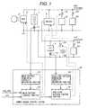
- Fig. 1shows a system construction showing one embodiment of the control system for the automotive power source system according to the present invention.
- a motor/generator 3is connected to the main battery 1 via an inverter 4.
- the motor/generator 3is operated upon starting up of the engine and thus serves as a starter, and is operated as a generator for supplying an electric power to a load when the engine is driven.
- the auxiliary battery 2 of 14V systemis charged by the main battery 1 via a DC/DC converter 5.
- Loads to be connected to the 14V systemincludes lamp loads 53, such as a head lamp, parking lamp.
- lamp loads 53such as a head lamp, parking lamp.
- filamenthas to be made thinner to be disadvantageous in view of duration. Therefore, it is typical to connect the lamps 53 to the 14V system.
- Load 54 for low voltage operationsuch as a power source of the control system is also connected to the 14V system.
- a power source control system 20includes a main battery remaining capacity measuring portion 21, a auxiliary battery remaining capacity measuring portion 23, a main battery control portion 22 and a second battery control portion 24 and provides a command to the inverter 4 and the DC/DC converter 5 depending upon size of the electrical loads 51 to 54 and remaining capacities of the batteries 1 and 2.
- the power source control system 20performs operation for preventing lowering of remaining capacities of the batteries 1 and 2 by shutting off switches 61, 62, 63 and 64 of the electrical loads, as required.
- the main battery residual capacity measuring portion 21measures a remaining capacity of the main battery on the basis of information of a current sensor 11.
- the auxiliary battery remaining capacity measuring portion 23measured the remaining capacity of the auxiliary battery 2 on the basis of information of a current sensor 12.
- the measurementis performed by integrating charge and discharge current flowing through the battery, for example.
- a method for performing measurement from a voltage and a current of the batterya method for performing correction of the remaining capacity derived by the integrated value of the current by a voltage and current value.
- any suitable measuring methodmay be used adapting to kind of the battery (lead, nickel hydride, lithium ion and so forth).
- the main battery control portion 22controls charging and discharging of the main battery 1 using information of the remaining capacity measured by the main battery remaining capacity measuring portion 21 , key switch information KeySW and information of engine revolution speed ⁇ e.
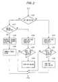
- Fig. 2is a flowchart showing operation of the main battery control portion to be used in one embodiment of the control system for the automotive power source system according to the present invention.
- the main battery control portion 22makes judgment whether the key switch is ON or not on the basis of the key switch information KeySW.
- the key switchis ON, the process is advanced to step s110, and when the key switch is OFF, the process is advanced to step s170.
- step s110the main battery control portion 22 makes judgment whether the engine is in operation or not.
- the processis advanced to step s120, and when the engine is not in operation, the process is advanced to step s140.
- the main battery control portion 22calculates a target value of charging and discharging current of the battery depending upon remaining capacity of the battery measured by the main battery remaining capacity measuring portion 21.
- the target value of charging and discharging currentis set depending upon error between the remaining capacity of the battery from a target remaining capacity. For example, assuming that remaining battery remaining capacity is 70% (taking fully charged condition as 100%), if the current remaining capacity is 60%, a charge current target value is derived by multiplying a difference of 10% by an appropriate coefficient.
- the main battery control portion 22provides the current target value calculated at step s120, to the inverter 4 as the command. Since a difference between the generation output of the motor/generator 3 and load power is charged to the battery, in the inverter 4, the generation output of the motor/generator 3 is controlled so that the battery current becomes the commanded current target value.
- the main battery control portion 22effects control so that the motor/generator 3 is operated as the generator by revolution of the engine for supplying electric power to the electrical load.
- the main battery control portion 22checks if the remaining capacity of the main battery 1 as measured by the main battery remaining capacity measuring portion 21 is not lowered below a predetermined lower limit from time to time.
- a predetermined lower limita value capable of outputting electric power necessary for starting up the engine.
- the lower limitis preliminarily determined at 30% of full charge. The characteristics is different depending upon the kind of the battery and output characteristics is variable depending upon the temperature. The lower limit is set in consideration of this.
- the main battery control portion 22makes judgment whether the remaining capacity is greater than the lower limit value or not. If the remaining capacity is greater than the lower limit value, the process directly goes end. If the remaining capacity is smaller than the lower limit value, the process is advanced to step s160.
- the main battery control portion 22When the remaining capacity becomes smaller than the lower limit value, the main battery control portion 22 provides a command for starting up the engine for the inverter 4 at step s160. When the engine is started up, since the motor/generator 3 is operated as generator, the remaining capacity of the main battery 1 will not be lowered any further.
- the engineis stopped automatically.
- the electrically actuated air conditioner 51is kept in operation even while the engine operation is interrupted, the remaining capacity of the main battery 1 is possibly lowered below the predetermined lower limit value to cause difficulty in re-starting of the engine.
- lowering of the remaining capacity of the main batterycan be prevented by starting up the engine through steps s140 to s160 to enable re-starting of the engine.
- step s160After starting up the engine at step s160, it is possible to consume out the fuel if the engine is operated for a long period. Therefore, remaining amount of fuel is checked to stop the engine when the remaining amount of the fuel becomes less than or equal to a certain value.
- the main battery control portion 22checks whether the remaining capacity of the main battery 1 as measured by the main battery remaining capacity measuring portion 21 is lowered below the predetermined lower limit value from time to time.
- the lower limit value of the remaining capacitya value capable of outputting necessary power for starting up the engine, such as 30% of full charge condition, is preliminarily set. Characteristics is different depending upon the kind of the battery, and also the output characteristics can also be varied depending upon temperature. Therefore, the lower limit value is set in consideration with those characteristics.
- step s180the main battery control portion 22 makes judgment whether the remaining capacity is greater than the lower limit value or not. If the remaining capacity is greater than the lower limit value and the remaining capacity, the process directly goes end. On the other hand, if the remaining capacity is smaller than the lower limit value, the process is advanced to step s190.
- the main battery control portion 22shut off a switch 61 of the electrical load in operation at step s190. By this, lowering of the remaining capacity of the main battery 1 can be prevented.
- step s160When the engine may be automatically started out while the key switch is held OFF, it may be possible to advance the process to step s160 to provide the command for starting up the engine. In case of parking in garage having high sealing ability, starting up of the engine is not desirable. Therefore, by providing a button for permitting starting up of the engine while key switch is off, it may be possible to advance the process to step s160 for automatically start up the engine when the button is turned ON.
- the electrical loadsuch as the electrically actuated air conditioner can be actuated. Furthermore, since remaining capacity of the battery is constantly monitored, it can be prevented to lower the remaining capacity of the battery to be incapable of starting up of the engine. It should be noted that while discussion has been given in terms of the electrically actuated air condition as the electrical load, similar is true for the electrical load, such as power window, defroster and so forth.
- the shown embodimentis effective even in the case where the air conditioner or so forth is automatically actuated by a timer.
- itmay be desired to actuate the air conditioner in advance of starting driving of the vehicle. Bt preliminarily setting starting up time of the air condition by the timer, the vehicular cabin may be air conditioned at comfortable temperature upon starting driving.
- the capacity of the main batteryis sufficiently large, it is possible to actuate the electrically actuated air conditioner without starting up the engine.
- the remaining capacity of the batteryis dropped below a minimum value, operation of the air condition is stopped or engine is stared up automatically. Therefore, lowering of the remaining capacity of the battery can be prevented.
- defroster, catalytic converter heating device and so forthmay be considered in addition to the electrically actuated air conditioner.
- the power source of the power source control system 20per se may also be shut off.
- the condition at step s190it becomes unnecessary to monitor the remaining capacity of the battery until the engine is started upon in response to turning ON of the key switch. Since the power source control system 20 consumes electrical power while a little, wasteful power consumption can be avoiding by interrupting operation of the power source control system 20. Particularly, when the vehicle is left in operative for a long period, shutting of the power source for the power source control system may be effective. The power source for the control system 20 which is once shut off is resumed when the key switch is turned ON.
- the threshold value of the remaining capacity of the batterymay be provided in plural depending upon preference of the electrical load. For example, concerning the air conditioner, it can be shut off when the remaining capacity becomes lower than or equal to 30%. Concerning lamp load (14V system), for high importance in security, it is set to operate until the remaining capacity is lowered less than or equal to 20%. By this, it becomes possible to operate the load having higher preferential order for longer period.
- Fig. 3is a flowchart showing operation of the auxiliary battery control portion to be employed in one embodiment of the control system for the automotive power source system according to the present invention.
- the auxiliary battery control portion 24makes judgment whether the load for the 14V system can be operated or not. Since the main battery control portion 22 provides a command whether the load for 14V system can be operated or not, to the auxiliary battery control portion 24, the auxiliary battery control portion 24 makes judgment on the basis of the command from the main battery portion 22. As viewed from the main battery side, overall 14V including the DC/DC converter 5 can be regarded as one electrical load. It can be considered as one of the electrical load which can be operated even upon stopping of the engine or turning OFF of the key switch similarly to the electrically actuated air conditioner 51. Accordingly, when step s190 of Fig. 2 is reached, the main battery control portion 22 issues a command for disabling operation of the 14V system, and otherwise, enabling operation of the 14V system, to the auxiliary battery control portion 24.
- the auxiliary battery control portion 24calculates a target value of charge and discharge current of the auxiliary battery 2 on the basis of information of the remaining capacity of the auxiliary battery measured by the auxiliary battery remaining capacity measuring portion 23.
- the auxiliary battery control portion 24provides the target value of the DC/DC converter 5.
- the target value of charge and discharge currentis zero in steady state to supply only load current of the 14V system by the DC/DC converter 5.
- the remaining capacity of the auxiliary battery 2is reduced. The reduced capacity is compensated by charging when the load becomes lighter.
- the auxiliary battery control portion 24stops the operation of the DC/DC converter 5. By this, power supply to the 14V system from the main battery 1 is stopped to prevent lowering of the remaining capacity of the main battery 1.
- the auxiliary battery control portion 24checks whether the remaining capacity of the auxiliary battery 2 measured by the auxiliary battery remaining capacity measuring portion 23 is greater than or equal to a predetermined lower limit value. Even when the operation of the DC/DC converter 5 is stopped, the capacity of the auxiliary battery is remained, load of the 14V system, such as the lam load 53 can be operated.
- the auxiliary battery control portion 24makes judgment whether the remaining capacity is greater than or equal to the lower limit value or not. If the remaining capacity is greater than the lower limit value, the process directly goes end. If the remaining capacity is smaller than the lower limit value, the process is advanced to step s260.
- the auxiliary battery control portion 24shut off the switch 63 of the electrical load of the 14V system, at step s260. By this, lowering of the remaining capacity of the auxiliary battery 2 can be prevented.
- auxiliary batteryit does not influence for starting up of the engine even when the remaining capacity becomes zero. Therefore, it is possible to skip the processes of steps s240 and s260.
- lower limit value of the remaining capacitymay be set for checking from time to time.
- the DC/DC converter 5keeps operation until the remaining capacity of the main battery 1 is lowered to the lower limit value for supplying power to the load, and subsequently, the power is supplied to the load from the auxiliary battery 2 until the remaining capacity of the auxiliary battery 2 is lowered to the lower limit value.
- auxiliary battery remaining capacity measuring portion 23if it is not necessary to manage the remaining capacity, a method to control only by the voltage of the battery may also be used.
- the voltage of the 14V systemis detected by a voltage sensor, the DC/DC converter 5 may be controlled so that the voltage becomes the target value.
- the present inventionis effectively applicable at any value of voltage. Even when the voltage of the main battery is as high as 200 to 300V as that for the hybrid drive type vehicle, the present invention is applicable.
- the electrical loadsuch as the electrically actuated air conditioner, lamps and so forth may be operated even when the engine operation is interrupted or key switch is held OFF with preventing lowering of the remaining capacity of the main battery.
- Fig. 4is an illustration showing a system construction showing the construction of another embodiment of the control system for the automotive power source system according to the present invention. It should be noted that like reference numerals to those in Fig. 1 identifies like components, and detailed discussion for such common components will be omitted for avoiding redundant disclosure and whereby to keep the disclosure simple enough to facilitate clear understanding of the invention.
- the power source control system 20Ahas a main battery remaining capacity measuring portion 21 and a main battery control portion 22A.
- Operation of the main battery control portion 22Ais basically similar to the flowchart shown in Fig. 2.
- the main battery control portion 22Aprovides a current target value calculated at step s120 to the alternator 7 as a command.
- generated poweris adjusted to control toward the target value.
- a difference between the generation output of the alternator 7 and the load poweris charged to the battery.
- the main battery control portion 22Aprovides a command for starting up the engine for the starter at step s160. Once the engine is started up, power is generated by the alternator 7. Therefore, the remaining capacity of the main battery 1 is not lowered any further.
- the electrical loadsuch as the electrically actuated air condition, lamps and so forth can be operated even while the engine is stopped and the key switch is held OFF with preventing lowering of the remaining capacity of the main battery.
- the electrically actuated air condition, lamps and so forthcan be operated even while the engine is stopped and the key switch is held OFF with preventing lowering of the remaining capacity of the main battery.
Landscapes
- Engineering & Computer Science (AREA)
- Power Engineering (AREA)
- Transportation (AREA)
- Mechanical Engineering (AREA)
- Life Sciences & Earth Sciences (AREA)
- Sustainable Development (AREA)
- Sustainable Energy (AREA)
- Business, Economics & Management (AREA)
- Emergency Management (AREA)
- Charge And Discharge Circuits For Batteries Or The Like (AREA)
- Electric Propulsion And Braking For Vehicles (AREA)
- Control Of Vehicle Engines Or Engines For Specific Uses (AREA)
Abstract
Description
The present invention relates generally to a powercontroller for a vehicle. More particularly, the inventionrelates to a control system for an automotive power source systemsuitable for controlling an automotive power source havinghigher voltage and higher capacity battery than the conventional14V system, such as 42V system.
In the recent years, for adapting to increasing ofelectrically actuated on-vehicle equipments, such aselectrically driven power steering, electrically actuated airconditioner and so forth, and increasing of capacity thereof.42V automotive power source system, in which 42V system powersource is added to the conventional 14 system power source,has been proposed. In the 42V system power source, since avoltage becomes three times higher than that of the 14V system,a current can be one third to reduce power loss and to saveweight of a harness. Also, it is facilitated to adaptation fora large capacity load. Also, a capacity of the battery is largerthan that of the conventional battery, and of nickel hydridebattery, lithium ion battery and so forth can be applied inplace of the conventional lead acid battery toward the future. conventional 14V system has to be maintained as is. Therefore,recently, a system having both of a main battery of 42V systemand a auxiliary battery of 14v system and connecting bothbatteries through a DC/DC converter for controlling chargingfrom the main battery to the auxiliary battery, has been proposed.
However, in the recently proposed system, the followingproblem can be encountered. Namely, utilizing large capacityof the battery of 42V system, it becomes possible to operateelectrical load, such as electrically actuated air conditionereven while the engine is not driven. However, when a remainingcapacity of the main battery becomes small, it becomes impossibleto start-up the engine.
Also, for example, when the lamps are connected to the14V system, it becomes necessary to turn the lamps ON even whenthe key switched is held OFF. However, when the battery capacityof the auxiliary battery is small, remaining capacity isinstantly lowered to lower remaining capacity of the main batterywhen the lamps maintained ON.
The first object of the present invention is to providea control system for an automotive power source system whichcan operate electrical load upon stopping of engine or turningOFF of a key switch, and lowering of remaining capacity of amain battery can be prevented.
The second object of the present invention is to providea control system for an automotive power source which can operateelectrical load of low voltage system while a key switch isheld OFF even when a capacity of a auxiliary battery is small.
In order to accomplish the above-mentioned objects, oneaspect of the present invention, a control system for anautomotive power source system having a control portioncontrolling operation of a power generator and an electricalload mounted on an automotive vehicle, comprises:
With the construction set forth above, when the engineis stopped or the key switch is held OFF, operation of the powerload is possible, and lowering of the remaining capacity ofthe main battery can be prevented.
Preferably, the control portion may set a plurality ofthreshold values of the remaining capacity correspondingpreference of the power load to sequentially stop the powerload having low preference in sequential order according tolowering of remaining capacity of the battery.
Preferably, the control portion may operate apredetermined power load when the engine is stopped or the keyswitch is held OFF to start up the engine when the remainingcapacity of the battery is lowered below a predetermined value.
Preferably, the control system may comprise a switch fordetermining whether starting up of engine is permitted or notwhen the key switch is held OFF, the control portion may startup the engine only when the switch is ON, when the key switchis OFF.
Preferably, the control system may further comprisemeans for inputting a remaining amount information of fuel,the control portion may stop the engine when remaining amountof fuel becomes smaller than a predetermined value after startingup the engine.
Further preferably, the control port ion may stop operationof the power load when the remaining capacity of the batterybecomes smaller than a predetermined value, and stops operationof the control systemperse.
Preferably, the control portion may resume operation whenthe key switch is turned ON after once stopping the operationof the control portionperse.
According to another aspect of the present invention,a control system for an automotive power source system havinga control portion controlling a power generator or power loadmounted on an automotive vehicle, comprises:
The present invention will be understood more fully fromthe detailed description given hereinafter and from theaccompanying drawings of the preferred embodiment of the presentinvention, which, however, should not be taken to be limitativeto the invention, but are for explanation and understandingonly.
In the drawings:
The present invention will be discussed hereinafter indetail in terms of the preferred embodiment of a control systemfor an automotive power source system according to the presentinvention with reference to the accompanying drawings. In thefollowing description, numerous specific details are set forthin order to provide a thorough understanding of the presentinvention. It will be obvious, however, to those skilled inthe art that the present invention may be practiced withoutthese specific details. In other instance, well-knownstructure are not shown in detail in order to avoid unnecessaryobscurity of the present invention.
The construction and operation of one embodiment of acontrol system for an automotive power source system will bediscussed hereinafter with reference to Figs. 1 to 3.
At first, a construction of the shown embodiment of thecontrol system for the automotive power source system will bediscussed with reference to Fig. 1.
Fig. 1 shows a system construction showing one embodimentof the control system for the automotive power source systemaccording to the present invention.
The shown embodiment of the control system for theautomotive power source system will be discussed in terms ofan example, in which a main battery of 42V system and aauxiliarybattery 2 of 14V system. A motor/generator 3 is connected tothemain battery 1 via aninverter 4. The motor/generator 3is operated upon starting up of the engine and thus serves asa starter, and is operated as a generator for supplying anelectric power to a load when the engine is driven. Theauxiliarybattery 2 of 14V system is charged by themain battery 1 viaa DC/DC converter 5.
To the 42V system and the 14V system, a large number ofelectrical loads air conditioner 51 or ahigh power load 52, such as an electrically actuatedor motor driven power steering system are mainly connected.Loads to be connected to the 14V system includeslamp loads 53, such as a head lamp, parking lamp. For connecting thelamps 53 to the 42V system, filament has to be made thinner to bedisadvantageous in view of duration. Therefore, it is typicalto connect thelamps 53 to the 14V system.Load 54 for low voltageoperation, such as a power source of the control system is alsoconnected to the 14V system.
A powersource control system 20 includes a main batteryremainingcapacity measuring portion 21, a auxiliary batteryremainingcapacity measuring portion 23, a mainbattery controlportion 22 and a secondbattery control portion 24 and providesa command to theinverter 4 and the DC/DC converter 5 dependingupon size of theelectrical loads 51 to 54 and remainingcapacities of thebatteries source control system 20 performs operation for preventinglowering of remaining capacities of thebatteries switches
The main battery residualcapacity measuring portion 21measures a remaining capacity of the main battery on the basisof information of acurrent sensor 11. The auxiliary batteryremainingcapacity measuring portion 23 measured the remainingcapacity of theauxiliary battery 2 on the basis of informationof acurrent sensor 12. As measuring method of remainingcapacity of the battery, the measurement is performed byintegrating charge and discharge current flowing through thebattery, for example. Other than the method set forth above,a method for performing measurement from a voltage and a currentof the battery, a method for performing correction of theremaining capacity derived by the integrated value of the currentby a voltage and current value. On the other hand, any suitablemeasuring method may be used adapting to kind of the battery (lead, nickel hydride, lithium ion and so forth).
The mainbattery control portion 22 controls chargingand discharging of themain battery 1 using information of theremaining capacity measured by the main battery remainingcapacity measuring portion 21 , key switch information KeySWand information of engine revolution speed ωe.
Here, discussion will be given for operation of the mainbattery control portion 22.
Fig. 2 is a flowchart showing operation of the main batterycontrol portion to be used in one embodiment of the controlsystem for the automotive power source system according to thepresent invention.
At step s100, the mainbattery control portion 22 makesjudgment whether the key switch is ON or not on the basis ofthe key switch information KeySW. When the key switch is ON,the process is advanced to step s110, and when the key switchis OFF, the process is advanced to step s170.
When the key switch is ON, at step s110, the mainbatterycontrol portion 22 makes judgment whether the engine is inoperation or not. When the engine is in operation, the processis advanced to step s120, and when the engine is not in operation,the process is advanced to step s140.
When the key switch is ON and the engine is in operation,at step s120, the mainbattery control portion 22 calculatesa target value of charging and discharging current of the battery depending upon remaining capacity of the battery measured bythe main battery remainingcapacity measuring portion 21. Thetarget value of charging and discharging current is set dependingupon error between the remaining capacity of the battery froma target remaining capacity. For example, assuming thatremaining battery remaining capacity is 70% (taking fullycharged condition as 100%), if the current remaining capacityis 60%, a charge current target value is derived by multiplyinga difference of 10% by an appropriate coefficient.
Next, at step s130, the mainbattery control portion 22provides the current target value calculated at step s120, totheinverter 4 as the command. Since a difference between thegeneration output of the motor/generator 3 and load power ischarged to the battery, in theinverter 4, the generation outputof the motor/generator 3 is controlled so that the battery currentbecomes the commanded current target value.
By this, when the key switch is ON and the engine is inoperation, the mainbattery control portion 22 effects controlso that the motor/generator 3 is operated as the generator byrevolution of the engine for supplying electric power to theelectrical load.
Next, when the key switch is ON and the engine is no inoperation, at step s140, the mainbattery control portion 22checks if the remaining capacity of themain battery 1 as measuredby the main battery remainingcapacity measuring portion 21 is not lowered below a predetermined lower limit from time totime. As the lower limit of the remaining capacity, a valuecapable of outputting electric power necessary for startingup the engine. For example, the lower limit is preliminarilydetermined at 30% of full charge. The characteristics isdifferent depending upon the kind of the battery and outputcharacteristics is variable depending upon the temperature.The lower limit is set in consideration of this.
At step s150, the mainbattery control portion 22 makesjudgment whether the remaining capacity is greater than thelower limit value or not. If the remaining capacity is greaterthan the lower limit value, the process directly goes end. Ifthe remaining capacity is smaller than the lower limit value,the process is advanced to step s160.
When the remaining capacity becomes smaller than the lowerlimit value, the mainbattery control portion 22 provides acommand for starting up the engine for theinverter 4 at steps160. When the engine is started up, since the motor/generator 3 is operated as generator, the remaining capacity of themainbattery 1 will not be lowered any further.
For example, in case of the vehicle having an idle stopfunction, when the vehicle stops at the traffic signal, theengine is stopped automatically. When the electricallyactuatedair conditioner 51 is kept in operation even whilethe engine operation is interrupted, the remaining capacity of themain battery 1 is possibly lowered below the predeterminedlower limit value to cause difficulty in re-starting of theengine. Even in such idle stop function is provided, loweringof the remaining capacity of the main battery can be preventedby starting up the engine through steps s140 to s160 to enablere-starting of the engine.
While the engine operation is interrupted by the idlestop function in the foregoing example, similar is true evenin the case when the vehicle is stopped at a motor tool in boardedcondition. In case of the electrically actuated air condition,it can be operated at stopping of the vehicle without startingup the engine. At this time, lowering of the remaining capacityof the main battery can be prevented.
On the other hand, upon starting up of the engine, itis required to control to check items to be normally checkedupon starting up of the engine, such as whether a shift leveris put in P (parking) range or N (neutral) range. On the otherhand, in consideration of subsequent travel, control is madeto check whether fuel is remained in an amount greater thanor equal to predetermined extent. When the engine cannot bestarted up in some reason, a process is advanced to step s190to shut off the electrical load.
On the other hand, after starting up the engine at steps160, it is possible to consume out the fuel if the engine isoperated for a long period. Therefore, remaining amount of fuel is checked to stop the engine when the remaining amount of thefuel becomes less than or equal to a certain value.
Next, discussion will be given for the case where thekey switch is held off. Similar is true when the key is notinserted in a key cylinder. When the key switching is turnedOFF, many power loads are switched off simultaneously. However,predetermined some electrical loads, such as the electricallyactuatedair conditioner 51 and so forth may be set to enableoperation even while the key switch is held off.
Therefore, at step s170, the mainbattery control portion 22 checks whether the remaining capacity of themain battery 1 as measured by the main battery remainingcapacity measuringportion 21 is lowered below the predetermined lower limit valuefrom time to time. As the lower limit value of the remainingcapacity, a value capable of outputting necessary power forstarting up the engine, such as 30% of full charge condition,is preliminarily set. Characteristics is different dependingupon the kind of the battery, and also the output characteristicscan also be varied depending upon temperature. Therefore, thelower limit value is set in consideration with thosecharacteristics.
Then, at step s180, the mainbattery control portion 22makes judgment whether the remaining capacity is greater thanthe lower limit value or not. If the remaining capacity isgreater than the lower limit value and the remaining capacity, the process directly goes end. On the other hand, if theremaining capacity is smaller than the lower limit value, theprocess is advanced to step s190.
When the remaining capacity becomes smaller than the lowerlimit value, the mainbattery control portion 22 shut off aswitch 61 of the electrical load in operation at step s190.By this, lowering of the remaining capacity of themain battery 1 can be prevented.
When the engine may be automatically started out whilethe key switch is held OFF, it may be possible to advance theprocess to step s160 to provide the command for starting upthe engine. In case of parking in garage having high sealingability, starting up of the engine is not desirable. Therefore,by providing a button for permitting starting up of the enginewhile key switch is off, it may be possible to advance the processto step s160 for automatically start up the engine when thebutton is turned ON.
As set forth above, with the shown embodiment, even whenthe engine is not driven, the electrical load, such as theelectrically actuated air conditioner can be actuated.Furthermore, since remaining capacity of the battery isconstantly monitored, it can be prevented to lower the remainingcapacity of the battery to be incapable of starting up of theengine. It should be noted that while discussion has been givenin terms of the electrically actuated air condition as the electrical load, similar is true for the electrical load, suchas power window, defroster and so forth.
On the other hand, the shown embodiment is effective evenin the case where the air conditioner or so forth is automaticallyactuated by a timer. In winter or summer, it may be desiredto actuate the air conditioner in advance of starting drivingof the vehicle. Bt preliminarily setting starting up time ofthe air condition by the timer, the vehicular cabin may be airconditioned at comfortable temperature upon starting driving.When the capacity of the main battery is sufficiently large,it is possible to actuate the electrically actuated airconditioner without starting up the engine. On the other hand,if the remaining capacity of the battery is dropped below aminimum value, operation of the air condition is stopped orengine is stared up automatically. Therefore, lowering of theremaining capacity of the battery can be prevented. As theelectrical load effective of starting by timer before startingdriving, defroster, catalytic converter heating device and soforth may be considered in addition to the electrically actuatedair conditioner.
It should be noted that, at step s190, at the same timeof shutting of theswitch 61 of the electrical load, the powersource of the powersource control system 20perse may alsobe shut off. When the condition at step s190 is established,it becomes unnecessary to monitor the remaining capacity of the battery until the engine is started upon in response toturning ON of the key switch. Since the powersource controlsystem 20 consumes electrical power while a little, wastefulpower consumption can be avoiding by interrupting operationof the powersource control system 20. Particularly, when thevehicle is left in operative for a long period, shutting ofthe power source for the power source control system may beeffective. The power source for thecontrol system 20 whichis once shut off is resumed when the key switch is turned ON.
On the other hand, at step s190, upon shutting off theload, the threshold value of the remaining capacity of the batterymay be provided in plural depending upon preference of theelectrical load. For example, concerning the air conditioner,it can be shut off when the remaining capacity becomes lowerthan or equal to 30%. Concerning lamp load (14V system), forhigh importance in security, it is set to operate until theremaining capacity is lowered less than or equal to 20%. Bythis, it becomes possible to operate the load having higherpreferential order for longer period.
Next, discussion will be given for operation of theauxiliarybattery control portion 24 with reference to Fig.3.
Fig. 3 is a flowchart showing operation of the auxiliarybattery control portion to be employed in one embodiment ofthe control system for the automotive power source system according to the present invention.
Atstep 200, the auxiliarybattery control portion 24makes judgment whether the load for the 14V system can be operatedor not. Since the mainbattery control portion 22 provides acommand whether the load for 14V system can be operated or not,to the auxiliarybattery control portion 24, the auxiliarybattery control portion 24 makes judgment on the basis of thecommand from themain battery portion 22. As viewed from themain battery side, overall 14V including the DC/DC converter 5 can be regarded as one electrical load. It can be consideredas one of the electrical load which can be operated even uponstopping of the engine or turning OFF of the key switch similarlyto the electrically actuatedair conditioner 51. Accordingly,when step s190 of Fig. 2 is reached, the mainbattery controlportion 22 issues a command for disabling operation of the 14Vsystem, and otherwise, enabling operation of the 14V system,to the auxiliarybattery control portion 24.
When the operation of the 14V system is enabled, at steps210, the auxiliarybattery control portion 24 calculates atarget value of charge and discharge current of theauxiliarybattery 2 on the basis of information of the remaining capacityof the auxiliary battery measured by the auxiliary batteryremainingcapacity measuring portion 23.
Next, at step s220, the auxiliarybattery control portion 24 provides the target value of the DC/DC converter 5. The target value of charge and discharge current is zero in steady stateto supply only load current of the 14V system by the DC/DCconverter 5. When the load power in excess of the maximum outputof the DC/DC converter 5 is transitionally generated, theremaining capacity of theauxiliary battery 2 is reduced. Thereduced capacity is compensated by charging when the load becomeslighter.
When the remaining capacity of themain battery 1 is loweredto make operation of the 14V system impossible, the auxiliarybattery control portion 24 stops the operation of the DC/DCconverter 5. By this, power supply to the 14V system from themain battery 1 is stopped to prevent lowering of the remainingcapacity of themain battery 1.
Next, atstep 240, the auxiliarybattery control portion 24 checks whether the remaining capacity of theauxiliary battery 2 measured by the auxiliary battery remainingcapacity measuringportion 23 is greater than or equal to a predetermined lowerlimit value. Even when the operation of the DC/DC converter 5 is stopped, the capacity of the auxiliary battery is remained,load of the 14V system, such as thelam load 53 can be operated.
Then, at step s250, the auxiliarybattery control portion 24 makes judgment whether the remaining capacity is greaterthan or equal to the lower limit value or not. If the remainingcapacity is greater than the lower limit value, the processdirectly goes end. If the remaining capacity is smaller than the lower limit value, the process is advanced to step s260.
When the remaining capacity of theauxiliary battery 2is dropped below the lower limit value, the auxiliarybatterycontrol portion 24 shut off the switch 63 of the electricalload of the 14V system, at step s260. By this, lowering of theremaining capacity of theauxiliary battery 2 can be prevented.
Concerning the auxiliary battery, it does not influencefor starting up of the engine even when the remaining capacitybecomes zero. Therefore, it is possible to skip the processesof steps s240 and s260. Depending upon kind of the battery,if making zero of the remaining capacity may influence forduration of the battery, lower limit value of the remainingcapacity may be set for checking from time to time.
In the method set forth above, when thelamp load 53connected to the 14V system or so forth is kept ON upon turningOFF of the key switch, the DC/DC converter 5 keeps operationuntil the remaining capacity of themain battery 1 is loweredto the lower limit value for supplying power to the load, andsubsequently, the power is supplied to the load from theauxiliarybattery 2 until the remaining capacity of theauxiliary battery 2 is lowered to the lower limit value.
In the foregoing discussion, while the auxiliary batteryremainingcapacity measuring portion 23 is provided, if it isnot necessary to manage the remaining capacity, a method tocontrol only by the voltage of the battery may also be used. In such case, the voltage of the 14V system is detected by avoltage sensor, the DC/DC converter 5 may be controlled so thatthe voltage becomes the target value.
On the other hand, the foregoing discussion has been givenin terms of 42V system of the main battery and 14V system ofthe auxiliary battery, the present invention is effectivelyapplicable at any value of voltage. Even when the voltage ofthe main battery is as high as 200 to 300V as that for the hybriddrive type vehicle, the present invention is applicable.
As set forth above, according to the shown embodimentof the present invention, the electrical load, such as theelectrically actuated air conditioner, lamps and so forth maybe operated even when the engine operation is interrupted orkey switch is held OFF with preventing lowering of the remainingcapacity of the main battery.
On the other hand, by making the capacity of the auxiliarybattery smaller, system cost can be reduced.
Next, construction and operation of another embodimentof the control system for the automotive power source systemaccording to the present invention will be discussed withreference to Fig. 4.
Fig. 4 is an illustration showing a system constructionshowing the construction of another embodiment of the controlsystem for the automotive power source system according to thepresent invention. It should be noted that like reference numerals to those in Fig. 1 identifies like components, anddetailed discussion for such common components will be omittedfor avoiding redundant disclosure and whereby to keep thedisclosure simple enough to facilitate clear understanding ofthe invention.
In the shown embodiment, in place of the motor/generator 3 shown in Fig. 3, atypical starter 6 and analternator 7 areemployed. The battery is onlymain battery 1 of 14V system.Accordingly, the powersource control system 20A has a mainbattery remainingcapacity measuring portion 21 and a mainbattery control portion 22A.
Operation of the main battery control portion 22A isbasically similar to the flowchart shown in Fig. 2.
However, at step s130, the main battery control portion22A provides a current target value calculated at step s120to thealternator 7 as a command. By adjusting a field voltageof thealternator 7, generated power is adjusted to controltoward the target value. A difference between the generationoutput of thealternator 7 and the load power is charged tothe battery.
On the other hand, when the remaining capacity is loweredbelow the lower limit value, the main battery control portion22A provides a command for starting up the engine for the starterat step s160. Once the engine is started up, power is generatedby thealternator 7. Therefore, the remaining capacity of themain battery 1 is not lowered any further.
As set forth above, by the shown embodiment, not onlyfor the 42V power source system having the motor/generator,but only the system constituted of the starter and alternator,or the power source system having only main battery of 14V system,the electrical load, such as the electrically actuated aircondition, lamps and so forth can be operated even while theengine is stopped and the key switch is held OFF with preventinglowering of the remaining capacity of the main battery.
According to the present invention, the electricallyactuated air condition, lamps and so forth can be operated evenwhile the engine is stopped and the key switch is held OFF withpreventing lowering of the remaining capacity of the mainbattery.
On the other hand, in the automotive power source systemhaving the main battery and the auxiliary battery, it becomespossible to operate the power of the low voltage system whilethe key switch is OFF even when the capacity of the auxiliarybattery is small.
Although the present invention has been illustrated anddescribed with respect to exemplary embodiment thereof, itshould be understood by those skilled in the art that theforegoing and various other changes, omission and additionsmay be made therein and thereto, without departing from thespirit and scope of the present invention. Therefore, the present invention should not be understood as limited to thespecific embodiment set out above but to include all possibleembodiments which can be embodied within a scope encompassedand equivalent thereof with respect to the feature set out inthe appended claims.
Claims (8)
- A control system for an automotive power source system having a controlportion controlling operation of a power generator (3) and an electrical loadmounted on an automotive vehicle, comprising:remaining capacity measuring means (21) for measuring a remaining capacityof a battery (1),said control portion driving a predetermined power load when an engine isstopped or a key switch is held OFF, and operation of said power load beingstopped when a remaining capacity of the battery (1) measured by saidremaining capacity measuring means (21) becomes smaller than apredetermined value.
- A control system for an automotive power source system as set forth in claim1, wherein said control portion sets a plurality of threshold values of theremaining capacity corresponding preference of said power load tosequentially stop the power load having low preference in sequential orderaccording to lowering of remaining capacity of the battery (1).
- A control system for an automotive power source system as set forth in claim1, wherein said control portion operates a predetermined power load when theengine is stopped or the key switch is held OFF to start up the engine when theremaining capacity of the battery (1) is lowered below a predetermined value.
- A control system for an automotive power source system as set forth in claim3, which comprises a switch for determining whether starting up of engine ispermitted or not when the key switch is held OFF, said control portion starts up the engine only when said switch is ON, whensaid key switch is OFF.
- A control system for an automotive power source system as set forth in claim3, which further comprises means for inputting a remaining amountinformation of fuel,
said control portion stops the engine when remaining amount of fuel becomessmaller than a predetermined value after starting up the engine. - A control system for an automotive power source system as set forth in claim1, wherein said control portion stops operation of said power load when theremaining capacity of the battery (1) becomes smaller than a predeterminedvalue, and stops operation of said control systemperse.
- A control system for an automotive power source system as set forth in claim6, wherein said control portion resumes operation when the key switch isturned ON after once stopping the operation of the control portionperse.
- A control system for an automotive power source system having a controlportion controlling a power generator (3) or power load mounted on anautomotive vehicle, comprising:remaining capacity measuring means (21) for measuring a remaining capacityof a battery, a main battery (1), an auxiliary battery (2) and a voltage converter(5) for charging from the main battery (1) to the auxiliary battery (2),said control portion operating said voltage converter (5) when engine isstopped or key switch is held OFF and stopping operation of said voltageconverter (5) when remaining capacity of the main battery (1) is loweredbelow a predetermined value.
Applications Claiming Priority (2)
| Application Number | Priority Date | Filing Date | Title |
|---|---|---|---|
| JP2000055370 | 2000-03-01 | ||
| JP2000055370AJP3549806B2 (en) | 2000-03-01 | 2000-03-01 | Automotive power supply controller |
Publications (2)
| Publication Number | Publication Date |
|---|---|
| EP1142748A2true EP1142748A2 (en) | 2001-10-10 |
| EP1142748A3 EP1142748A3 (en) | 2006-11-29 |
Family
ID=18576503
Family Applications (1)
| Application Number | Title | Priority Date | Filing Date |
|---|---|---|---|
| EP01103673AWithdrawnEP1142748A3 (en) | 2000-03-01 | 2001-02-23 | Power controller for a vehicle |
Country Status (3)
| Country | Link |
|---|---|
| US (2) | US6806588B2 (en) |
| EP (1) | EP1142748A3 (en) |
| JP (1) | JP3549806B2 (en) |
Cited By (8)
| Publication number | Priority date | Publication date | Assignee | Title |
|---|---|---|---|---|
| WO2006045366A1 (en)* | 2004-10-21 | 2006-05-04 | Kromberg & Schubert Gmbh & Co. Kg | Intelligent security connection device |
| DE10312483B4 (en)* | 2002-03-20 | 2006-11-16 | Yazaki Corp. | Arc prevention means |
| EP1750346B1 (en)* | 2005-08-05 | 2012-09-19 | Fujitsu Ten Limited | Engine control apparatus, control method and control system |
| EP2613954A4 (en)* | 2010-09-10 | 2015-09-02 | Allison Transm Inc | HYBRID SYSTEM |
| CN108495771A (en)* | 2016-02-10 | 2018-09-04 | 株式会社自动网络技术研究所 | The switching device of vehicle power supply and vehicle-mounted supply unit |
| DE102005040077B4 (en) | 2004-08-24 | 2018-12-20 | Denso Corporation | Vehicle power supply with two power supplies |
| DE102004008817B4 (en) | 2003-02-20 | 2022-01-27 | Ford Global Technologies, Llc | Method for charging a high-voltage battery in a multi-voltage electrical system of a motor vehicle, system for a motor vehicle and electric hybrid vehicle |
| EP4000983A1 (en)* | 2020-11-11 | 2022-05-25 | Yazaki Corporation | Power device |
Families Citing this family (83)
| Publication number | Priority date | Publication date | Assignee | Title |
|---|---|---|---|---|
| JP3549806B2 (en)* | 2000-03-01 | 2004-08-04 | 株式会社日立製作所 | Automotive power supply controller |
| JP2003048497A (en)* | 2001-08-07 | 2003-02-18 | Yazaki Corp | Power distribution system |
| JP3776348B2 (en) | 2001-12-10 | 2006-05-17 | 本田技研工業株式会社 | Vehicle power supply |
| JP3705490B2 (en)* | 2002-02-14 | 2005-10-12 | 矢崎総業株式会社 | Load drive device |
| DE10217235A1 (en)* | 2002-04-18 | 2003-10-30 | Philips Intellectual Property | Circuit arrangement for generating DC voltages |
| DE10231379B3 (en)* | 2002-05-24 | 2004-01-15 | Daimlerchrysler Ag | Drive system for a motor vehicle with an internal combustion engine and an electric machine |
| WO2003103120A1 (en)* | 2002-06-03 | 2003-12-11 | International Rectifier Corporation | Planar dc-dc converter for multi-volt electrical applications |
| US20040100148A1 (en)* | 2002-10-23 | 2004-05-27 | Tsuyoshi Kindo | Power control unit and vehicle-installed apparatus |
| JP4715079B2 (en)* | 2003-06-26 | 2011-07-06 | パナソニック株式会社 | Vehicle power supply |
| EP1524749A3 (en)* | 2003-10-14 | 2007-05-16 | KIM, Sunchae | Controller for electric power supply of electronic device supplied with electric power from battery of vehicle |
| JP4541719B2 (en)* | 2004-02-16 | 2010-09-08 | 富士重工業株式会社 | Vehicle power supply |
| US7202574B2 (en)* | 2004-06-14 | 2007-04-10 | C.E. Niehoff & Co. | System and method for electrical energy switching and control in a vehicle |
| JP4211715B2 (en) | 2004-08-23 | 2009-01-21 | 株式会社デンソー | In-vehicle power supply system |
| JP2006166121A (en)* | 2004-12-08 | 2006-06-22 | Fujitsu Ten Ltd | Communication control apparatus |
| JP2006304390A (en)* | 2005-04-15 | 2006-11-02 | Favess Co Ltd | Power supply device for hybrid vehicle |
| US7421323B2 (en)* | 2005-05-03 | 2008-09-02 | International Truck Intellectual Property Company, Llc | Automated vehicle battery protection with programmable load shedding and engine speed control |
| JP4491839B2 (en)* | 2005-09-07 | 2010-06-30 | 株式会社デンソー | Generator control device |
| JP2007138720A (en)* | 2005-11-14 | 2007-06-07 | Auto Network Gijutsu Kenkyusho:Kk | Load control system and idle stop vehicle equipped with the load control system |
| JP2007137275A (en)* | 2005-11-18 | 2007-06-07 | Toyota Motor Corp | Power control device |
| JP5247001B2 (en)* | 2006-01-11 | 2013-07-24 | 富士通テン株式会社 | Vehicle power supply control device |
| JP4655950B2 (en)* | 2006-02-03 | 2011-03-23 | トヨタ自動車株式会社 | Electric vehicle |
| US7626892B2 (en)* | 2006-05-01 | 2009-12-01 | Tai-Her Yang | Timing device with power winder |
| JP4929839B2 (en) | 2006-05-22 | 2012-05-09 | トヨタ自動車株式会社 | Charge / discharge control device for power storage device |
| JP4969943B2 (en)* | 2006-08-10 | 2012-07-04 | 株式会社デンソー | Battery charge / discharge current detector |
| US7673713B2 (en)* | 2006-10-26 | 2010-03-09 | Caterpillar Inc. | Multi-purpose mobile power generating machine |
| JP4144646B1 (en)* | 2007-02-20 | 2008-09-03 | トヨタ自動車株式会社 | Electric vehicle, vehicle charging device, and vehicle charging system |
| US7761198B2 (en)* | 2007-06-25 | 2010-07-20 | General Electric Company | Methods and systems for power system management |
| JP5335207B2 (en)* | 2007-07-05 | 2013-11-06 | キヤノン株式会社 | Electronics |
| US8334679B2 (en) | 2008-01-22 | 2012-12-18 | Honda Motor Co., Ltd. | ACG output voltage control |
| US7986055B2 (en)* | 2008-01-22 | 2011-07-26 | Honda Motor Co., Ltd. | Adjustment of control strategy based on temperature |
| US20090183712A1 (en)* | 2008-01-22 | 2009-07-23 | Richard Owens | Idle speed adjustment system |
| US8030881B2 (en)* | 2008-01-22 | 2011-10-04 | Honda Motor Co., Ltd. | Battery control system and method |
| US7912618B2 (en)* | 2008-01-22 | 2011-03-22 | Honda Motor Co., Ltd. | Backup relay cut control system |
| US8217631B2 (en)* | 2008-01-22 | 2012-07-10 | Honda Motor Co., Ltd. | ACG output voltage control |
| JP5200576B2 (en)* | 2008-02-21 | 2013-06-05 | トヨタ自動車株式会社 | In-vehicle device control system |
| US8125181B2 (en)* | 2008-09-17 | 2012-02-28 | Toyota Motor Engineering & Manufacturing North America, Inc. | Method and apparatus for hybrid vehicle auxiliary battery state of charge control |
| JP5238431B2 (en)* | 2008-09-26 | 2013-07-17 | 本田技研工業株式会社 | Vehicle load control device |
| US7960857B2 (en)* | 2008-12-02 | 2011-06-14 | General Electric Company | System and method for vehicle based uninterruptable power supply |
| KR101029358B1 (en)* | 2009-02-20 | 2011-04-13 | 박영한 | Automotive Power Management Device |
| FR2950499B1 (en)* | 2009-09-23 | 2011-09-09 | Peugeot Citroen Automobiles Sa | CONTROL DEVICE FOR THE RESETTING OF A RESTART OF AN ELECTRONIC MEMBER OF A COMMUNICATION NETWORK |
| US8473131B2 (en)* | 2009-09-28 | 2013-06-25 | Powerhydrant Llc | Method and system for charging electric vehicles |
| US8446128B2 (en)* | 2009-11-02 | 2013-05-21 | Honda Motor Co., Ltd. | Vehicle battery management system and method |
| DE102010001243A1 (en)* | 2010-01-27 | 2011-07-28 | SB LiMotive Company Ltd., Kyonggi | Battery system for μ-hybrid vehicles with high power consumers |
| DE102010001244A1 (en)* | 2010-01-27 | 2011-07-28 | SB LiMotive Company Ltd., Kyonggi | Battery system for micro-hybrid vehicles with high power consumers |
| CN102753379B (en) | 2010-02-09 | 2015-12-09 | 丰田自动车株式会社 | Power supply system of electric vehicle and control method thereof |
| JP2011172318A (en)* | 2010-02-16 | 2011-09-01 | Omron Automotive Electronics Co Ltd | Power supply system, and power supply control method |
| CN102195333A (en)* | 2010-03-17 | 2011-09-21 | 新神户电机株式会社 | Direct-current power source apparatus |
| US20110301789A1 (en)* | 2010-06-04 | 2011-12-08 | Liam-Yung Sung | Battery power service management system and battery power service management method |
| JP5609401B2 (en)* | 2010-08-06 | 2014-10-22 | 株式会社豊田自動織機 | Vehicle power supply apparatus and power supply control method |
| WO2012056516A1 (en)* | 2010-10-26 | 2012-05-03 | トヨタ自動車株式会社 | Power supply device, vehicle provided with same, and power supply method |
| US8742615B2 (en) | 2011-01-14 | 2014-06-03 | GM Global Technology Operations LLC | Method and apparatus for electric power management in a vehicle |
| US9190868B2 (en)* | 2011-05-06 | 2015-11-17 | Ford Global Technologies, Llc | Vehicle and method for charging vehicle batteries |
| JP5183778B2 (en)* | 2011-07-15 | 2013-04-17 | 三菱電機株式会社 | Vehicle charging system |
| DE102012014471A1 (en)* | 2011-07-27 | 2013-01-31 | Marquardt Gmbh | Power supply circuit for electrical components |
| US8816530B2 (en) | 2011-09-29 | 2014-08-26 | Ford Global Technologies, Llc | System and method for managing electrical loads in a vehicle |
| US20130082639A1 (en)* | 2011-10-04 | 2013-04-04 | GM Global Technology Operations LLC | Electrical system having a primary energy source and a redundant rechargeable energy source |
| US9365115B2 (en)* | 2012-01-20 | 2016-06-14 | Ford Global Technologies, Llc | System and method for vehicle power management |
| KR101397023B1 (en)* | 2012-03-23 | 2014-05-20 | 삼성에스디아이 주식회사 | Battery pack and method for controlling the same |
| JP2013219982A (en)* | 2012-04-11 | 2013-10-24 | Toyota Industries Corp | Dc-ac inverter |
| DE102012108071B4 (en)* | 2012-08-31 | 2024-07-18 | Dr. Ing. H.C. F. Porsche Ag | Energy management system and method for operating a battery |
| FR2995466B1 (en)* | 2012-09-13 | 2014-08-29 | Renault Sa | SYSTEM AND METHOD FOR MANAGING THE POWER SUPPLY OF AT LEAST ONE AUTOMATIC RESTART EQUIPMENT OF A VEHICLE HEAT ENGINE |
| KR101323916B1 (en)* | 2012-10-30 | 2013-10-31 | 엘에스산전 주식회사 | Apparatus and method for early starting of vehicle |
| US10106038B2 (en)* | 2012-12-28 | 2018-10-23 | Johnson Controls Technology Company | Dual function battery system and method |
| JP5772839B2 (en)* | 2013-01-21 | 2015-09-02 | トヨタ自動車株式会社 | Vehicle power supply system and vehicle equipped with the same |
| US9493087B2 (en) | 2013-08-07 | 2016-11-15 | Powerhydrant Llc | Method and system for automatic charging of electric vehicles |
| KR101459946B1 (en)* | 2013-09-23 | 2014-11-07 | 현대자동차주식회사 | Power control system and method for vehicle power outlet |
| KR101459489B1 (en)* | 2013-09-26 | 2014-11-07 | 현대자동차 주식회사 | Method and system for controlling environmentally-friendly vehicle |
| JP2015180140A (en)* | 2014-03-19 | 2015-10-08 | 三洋電機株式会社 | Power supply system for vehicle |
| KR101468174B1 (en)* | 2014-03-20 | 2014-12-05 | 세화자동차주식회사 | Power control apparatus of a vehicle |
| US9461482B2 (en)* | 2014-04-15 | 2016-10-04 | Win Sheng Cheng | Multi-chemistry battery pack system |
| US9889753B2 (en)* | 2014-11-14 | 2018-02-13 | Lg Electronics Inc. | Driving apparatus for electric vehicle |
| FR3036078A1 (en)* | 2015-05-12 | 2016-11-18 | Peugeot Citroen Automobiles Sa | DEVICE FOR MONITORING THE USE OF TWO ELECTRIC ENERGY STORAGE MEANS OF A HYBRID VEHICLE FOR PERMANENTLY POWERING AN ELECTRICAL NETWORK |
| US10415213B2 (en)* | 2015-10-28 | 2019-09-17 | Cooper Gray Robotics, Llc | Remotely controlled construction equipment |
| JP6713330B2 (en)* | 2016-04-14 | 2020-06-24 | 株式会社デンソーテン | Vehicle power supply control device, vehicle power supply system, and power supply control method |
| KR101866063B1 (en)* | 2016-10-07 | 2018-06-08 | 현대자동차주식회사 | System for controlling relay of an auxiliary battery and method thereof |
| JP2019098782A (en)* | 2017-11-28 | 2019-06-24 | 矢崎総業株式会社 | Wire harness routing structure |
| DE102018103498A1 (en)* | 2018-02-16 | 2019-08-22 | Still Gmbh | Battery-powered truck with backup battery for onboard power supply |
| US11230192B2 (en)* | 2019-09-13 | 2022-01-25 | Ford Global Technologies, Llc | Vehicle battery monitoring assembly and monitoring method |
| EP4268345A1 (en)* | 2020-12-23 | 2023-11-01 | Medtronic, Inc. | Control logic to update battery capacity |
| US12265132B2 (en) | 2020-12-23 | 2025-04-01 | Medtronic, Inc. | Updating battery capacity after clinical implementation |
| GB2609975B (en)* | 2021-08-20 | 2023-11-15 | Jaguar Land Rover Ltd | Extended-use mode for an ancillary vehicle function |
| CN113682139B (en)* | 2021-08-27 | 2023-06-20 | 南华大学 | A load electric energy management method, system and device of an electric vaccination vehicle |
| CN115370516A (en)* | 2022-09-28 | 2022-11-22 | 岚图汽车科技有限公司 | A range-extended starting method, starting system and vehicle |
Family Cites Families (39)
| Publication number | Priority date | Publication date | Assignee | Title |
|---|---|---|---|---|
| US3646354A (en)* | 1970-11-05 | 1972-02-29 | Joe W Von Brimer | Electrical supervisory control |
| US3667025A (en)* | 1971-06-21 | 1972-05-30 | Gen Motors Corp | Dual voltage system |
| US3904947A (en)* | 1973-08-22 | 1975-09-09 | Roy E Crews | Vehicle mounted battery charging system for an electric motor vehicle |
| US3900784A (en)* | 1974-07-10 | 1975-08-19 | Eltra Corp | Converter for battery charger |
| GB1602462A (en)* | 1977-04-02 | 1981-11-11 | Lucas Industries Ltd | Battery charging systems for road vehicles |
| US4902956A (en)* | 1986-12-12 | 1990-02-20 | Sloan Jeffrey M | Safety device to prevent excessive battery drain |
| US4743830A (en)* | 1987-01-20 | 1988-05-10 | General Motors Corporation | Dual voltage electrical system |
| US4937528A (en)* | 1988-10-14 | 1990-06-26 | Allied-Signal Inc. | Method for monitoring automotive battery status |
| US5032825A (en)* | 1990-03-02 | 1991-07-16 | Motorola, Inc. | Battery capacity indicator |
| US5130659A (en)* | 1990-08-21 | 1992-07-14 | Sloan Jeffrey M | Battery Monitor |
| US5293076A (en)* | 1991-04-16 | 1994-03-08 | Mitsubishi Denki Kabushiki Kaisha | Vehicle control apparatus |
| JPH04347536A (en) | 1991-05-22 | 1992-12-02 | Honda Motor Co Ltd | Electric load limiter for vehicle |
| JPH0525947A (en) | 1991-07-25 | 1993-02-02 | Matsushita Electric Works Ltd | Shower room |
| JPH0558508A (en) | 1991-08-27 | 1993-03-09 | Ricoh Co Ltd | Full color copying machine |
| WO1993023263A1 (en)* | 1992-05-08 | 1993-11-25 | Field Bruce F | Electric hybrid vehicle |
| DE69309767T2 (en)* | 1992-05-15 | 1997-10-23 | Mitsubishi Motors Corp | Method for operating a hybrid vehicle |
| JP3167419B2 (en) | 1992-05-28 | 2001-05-21 | 株式会社アルファ | Automotive battery monitoring device |
| JPH0654410A (en)* | 1992-06-05 | 1994-02-25 | Fuji Electric Co Ltd | Electric system for electric motor vehicle |
| US5488283A (en)* | 1993-09-28 | 1996-01-30 | Globe-Union, Inc. | Vehicle battery system providing battery back-up and opportunity charging |
| JPH07128416A (en)* | 1993-11-04 | 1995-05-19 | Mitsubishi Motors Corp | Battery residual capacity meter for electric vehicles |
| JPH07274411A (en) | 1994-03-30 | 1995-10-20 | Mitsubishi Electric Corp | Vehicle power generation control device |
| JPH08240647A (en)* | 1995-03-03 | 1996-09-17 | Yazaki Corp | Battery remaining capacity calculation method and battery remaining capacity measuring device |
| JP2860772B2 (en)* | 1995-06-06 | 1999-02-24 | 株式会社エクォス・リサーチ | Hybrid vehicle |
| JP3329991B2 (en)* | 1995-07-03 | 2002-09-30 | 本田技研工業株式会社 | Electric vehicle control device |
| JPH09163510A (en)* | 1995-12-05 | 1997-06-20 | Suzuki Motor Corp | Electric vehicle charging control device |
| JP2830838B2 (en)* | 1996-05-30 | 1998-12-02 | 日本電気株式会社 | Circuit dividing method and device |
| US5783872A (en)* | 1996-07-25 | 1998-07-21 | Northrop Grumman Corporation | Auxiliary battery voltage/temperature compensation for automotive 12 volt system for electric vehicles |
| JP3719302B2 (en)* | 1997-03-05 | 2005-11-24 | 株式会社日本自動車部品総合研究所 | Battery remaining capacity meter and battery remaining capacity measuring method |
| FR2777395B1 (en)* | 1998-04-09 | 2000-06-09 | France Design | DEVICE AND METHOD FOR RECHARGING THE POWER BATTERY OF AN ELECTRIC VEHICLE |
| JPH11334497A (en) | 1998-05-22 | 1999-12-07 | Yazaki Corp | Battery rising prevention device and method |
| JP3515404B2 (en)* | 1999-01-29 | 2004-04-05 | 日産ディーゼル工業株式会社 | Power supply |
| JP2000245009A (en)* | 1999-02-24 | 2000-09-08 | Honda Motor Co Ltd | Hybrid vehicle |
| JP3540209B2 (en)* | 1999-08-25 | 2004-07-07 | 本田技研工業株式会社 | Hybrid vehicle control device |
| US6400589B2 (en)* | 2000-01-12 | 2002-06-04 | Toyota Jidosha Kabushiki Kaisha | Control apparatus for a power supply circuit including plural converter |
| US6346797B1 (en)* | 2000-01-24 | 2002-02-12 | Massachusetts Institute Of Technology | Load matched alternator system |
| DE10003731B4 (en)* | 2000-01-28 | 2012-01-26 | Robert Bosch Gmbh | Use of an electronic switching device for temporarily connecting a battery to a consumer in a two-voltage electrical system |
| JP3615445B2 (en)* | 2000-01-31 | 2005-02-02 | 三洋電機株式会社 | Hybrid car power supply |
| JP3549806B2 (en)* | 2000-03-01 | 2004-08-04 | 株式会社日立製作所 | Automotive power supply controller |
| JP3736300B2 (en)* | 2000-06-19 | 2006-01-18 | 株式会社日立製作所 | Automobile and power supply device thereof |
- 2000
- 2000-03-01JPJP2000055370Apatent/JP3549806B2/ennot_activeExpired - Fee Related
- 2001
- 2001-02-23EPEP01103673Apatent/EP1142748A3/ennot_activeWithdrawn
- 2001-02-27USUS09/793,560patent/US6806588B2/ennot_activeExpired - Fee Related
- 2004
- 2004-06-15USUS10/866,773patent/US6979977B2/ennot_activeExpired - Fee Related
Cited By (11)
| Publication number | Priority date | Publication date | Assignee | Title |
|---|---|---|---|---|
| DE10312483B4 (en)* | 2002-03-20 | 2006-11-16 | Yazaki Corp. | Arc prevention means |
| DE102004008817B4 (en) | 2003-02-20 | 2022-01-27 | Ford Global Technologies, Llc | Method for charging a high-voltage battery in a multi-voltage electrical system of a motor vehicle, system for a motor vehicle and electric hybrid vehicle |
| DE102005040077B4 (en) | 2004-08-24 | 2018-12-20 | Denso Corporation | Vehicle power supply with two power supplies |
| WO2006045366A1 (en)* | 2004-10-21 | 2006-05-04 | Kromberg & Schubert Gmbh & Co. Kg | Intelligent security connection device |
| EP1750346B1 (en)* | 2005-08-05 | 2012-09-19 | Fujitsu Ten Limited | Engine control apparatus, control method and control system |
| EP2613954A4 (en)* | 2010-09-10 | 2015-09-02 | Allison Transm Inc | HYBRID SYSTEM |
| US9358866B2 (en) | 2010-09-10 | 2016-06-07 | Allison Transmission, Inc. | Hybrid system |
| US10023184B2 (en) | 2010-09-10 | 2018-07-17 | Allison Transmission, Inc. | Hybrid system |
| CN108495771A (en)* | 2016-02-10 | 2018-09-04 | 株式会社自动网络技术研究所 | The switching device of vehicle power supply and vehicle-mounted supply unit |
| EP4000983A1 (en)* | 2020-11-11 | 2022-05-25 | Yazaki Corporation | Power device |
| US12109898B2 (en) | 2020-11-11 | 2024-10-08 | Yazaki Corporation | Power device |
Also Published As
| Publication number | Publication date |
|---|---|
| EP1142748A3 (en) | 2006-11-29 |
| US20010019224A1 (en) | 2001-09-06 |
| JP3549806B2 (en) | 2004-08-04 |
| US6806588B2 (en) | 2004-10-19 |
| US20040232881A1 (en) | 2004-11-25 |
| US6979977B2 (en) | 2005-12-27 |
| JP2001239902A (en) | 2001-09-04 |
Similar Documents
| Publication | Publication Date | Title |
|---|---|---|
| EP1142748A2 (en) | Power controller for a vehicle | |
| US6727676B2 (en) | Control device for hybrid vehicle | |
| JP3749143B2 (en) | Vehicle power supply | |
| US9919710B2 (en) | Power storage system | |
| US7049789B2 (en) | Automotive power supply system designed to ensure stability in charging storage batteries | |
| KR101103877B1 (en) | Variable voltage control method of hybrid vehicle | |
| US20180233943A1 (en) | Power supply system for vehicle | |
| KR102386115B1 (en) | Air conditioner without engine running for heating and cooling for truck | |
| CN110316176B (en) | Control device | |
| KR100867795B1 (en) | DC / DC converter operation control method of hybrid vehicle | |
| CN104052104A (en) | Vehicle-mounted power supply system | |
| GB2406362A (en) | A system and method for controlling starting and stopping, in particular standby mode, of a hybrid vehicle engine | |
| WO2008023245A2 (en) | Battery control system and battery control method | |
| US20190232788A1 (en) | Electrically driven vehicle | |
| JP3925166B2 (en) | Automatic engine start system | |
| JP2004328906A (en) | Hybrid vehicle charge control device | |
| CN114389323A (en) | Method for reducing the total power consumption of a parked vehicle | |
| JP2020192866A (en) | Vehicular power supply control device | |
| JP2005251579A (en) | Fuel cell system | |
| US6696815B1 (en) | Secondary battery control device and control method | |
| KR20220117033A (en) | Apparatus for controlling ldc of ev and method thereof | |
| JP7373113B2 (en) | Vehicle power control device | |
| JP5310640B2 (en) | Drive device | |
| US7970518B2 (en) | Method and system for keyless machine operation | |
| JP3178139B2 (en) | Control device for electric vehicle |
Legal Events
| Date | Code | Title | Description |
|---|---|---|---|
| PUAI | Public reference made under article 153(3) epc to a published international application that has entered the european phase | Free format text:ORIGINAL CODE: 0009012 | |
| AK | Designated contracting states | Kind code of ref document:A2 Designated state(s):AT BE CH CY DE DK ES FI FR GB GR IE IT LI LU MC NL PT SE TR | |
| AX | Request for extension of the european patent | Free format text:AL;LT;LV;MK;RO;SI | |
| PUAL | Search report despatched | Free format text:ORIGINAL CODE: 0009013 | |
| AK | Designated contracting states | Kind code of ref document:A3 Designated state(s):AT BE CH CY DE DK ES FI FR GB GR IE IT LI LU MC NL PT SE TR | |
| AX | Request for extension of the european patent | Extension state:AL LT LV MK RO SI | |
| RIC1 | Information provided on ipc code assigned before grant | Ipc:F02N 11/08 20060101ALI20061025BHEP Ipc:H02J 9/00 20060101AFI20061025BHEP | |
| RAP1 | Party data changed (applicant data changed or rights of an application transferred) | Owner name:HITACHI, LTD. | |
| RAP1 | Party data changed (applicant data changed or rights of an application transferred) | Owner name:HITACHI, LTD. | |
| 17P | Request for examination filed | Effective date:20070529 | |
| AKX | Designation fees paid | Designated state(s):DE FR GB | |
| RAP1 | Party data changed (applicant data changed or rights of an application transferred) | Owner name:HITACHI, LTD. | |
| 17Q | First examination report despatched | Effective date:20090212 | |
| STAA | Information on the status of an ep patent application or granted ep patent | Free format text:STATUS: THE APPLICATION IS DEEMED TO BE WITHDRAWN | |
| 18D | Application deemed to be withdrawn | Effective date:20090623 |