EP1137455B1 - Catheter having improved flexibility control - Google Patents
Catheter having improved flexibility controlDownload PDFInfo
- Publication number
- EP1137455B1 EP1137455B1EP99965209AEP99965209AEP1137455B1EP 1137455 B1EP1137455 B1EP 1137455B1EP 99965209 AEP99965209 AEP 99965209AEP 99965209 AEP99965209 AEP 99965209AEP 1137455 B1EP1137455 B1EP 1137455B1
- Authority
- EP
- European Patent Office
- Prior art keywords
- catheter
- wide
- segments
- core wire
- outer tube
- Prior art date
- Legal status (The legal status is an assumption and is not a legal conclusion. Google has not performed a legal analysis and makes no representation as to the accuracy of the status listed.)
- Expired - Lifetime
Links
- 239000012530fluidSubstances0.000claimsabstractdescription19
- 238000002399angioplastyMethods0.000abstractdescription13
- 238000000034methodMethods0.000description18
- 208000031481Pathologic ConstrictionDiseases0.000description5
- 230000008901benefitEffects0.000description3
- 210000004351coronary vesselAnatomy0.000description3
- 230000003247decreasing effectEffects0.000description3
- 230000002093peripheral effectEffects0.000description3
- 230000002792vascularEffects0.000description3
- 238000013459approachMethods0.000description2
- 238000013461designMethods0.000description2
- 239000011521glassSubstances0.000description2
- 239000000463materialSubstances0.000description2
- 210000005166vasculatureAnatomy0.000description2
- 239000004698PolyethyleneSubstances0.000description1
- 239000004642PolyimideSubstances0.000description1
- 238000002583angiographyMethods0.000description1
- 210000004204blood vesselAnatomy0.000description1
- 238000004891communicationMethods0.000description1
- 230000009977dual effectEffects0.000description1
- 230000006870functionEffects0.000description1
- 238000003780insertionMethods0.000description1
- 230000037431insertionEffects0.000description1
- 230000003902lesionEffects0.000description1
- 238000004519manufacturing processMethods0.000description1
- 239000002184metalSubstances0.000description1
- HLXZNVUGXRDIFK-UHFFFAOYSA-Nnickel titaniumChemical compound[Ti].[Ti].[Ti].[Ti].[Ti].[Ti].[Ti].[Ti].[Ti].[Ti].[Ti].[Ni].[Ni].[Ni].[Ni].[Ni].[Ni].[Ni].[Ni].[Ni].[Ni].[Ni].[Ni].[Ni].[Ni]HLXZNVUGXRDIFK-UHFFFAOYSA-N0.000description1
- 229910001000nickel titaniumInorganic materials0.000description1
- 230000037361pathwayEffects0.000description1
- -1polyethylenePolymers0.000description1
- 229920000573polyethylenePolymers0.000description1
- 229920001721polyimidePolymers0.000description1
- 238000003825pressingMethods0.000description1
- 230000008569processEffects0.000description1
- 239000007787solidSubstances0.000description1
- 229910001220stainless steelInorganic materials0.000description1
- 239000010935stainless steelSubstances0.000description1
- 230000007704transitionEffects0.000description1
- 208000019553vascular diseaseDiseases0.000description1
Images
Classifications
- A—HUMAN NECESSITIES
- A61—MEDICAL OR VETERINARY SCIENCE; HYGIENE
- A61M—DEVICES FOR INTRODUCING MEDIA INTO, OR ONTO, THE BODY; DEVICES FOR TRANSDUCING BODY MEDIA OR FOR TAKING MEDIA FROM THE BODY; DEVICES FOR PRODUCING OR ENDING SLEEP OR STUPOR
- A61M25/00—Catheters; Hollow probes
- A61M25/10—Balloon catheters
- A61M25/104—Balloon catheters used for angioplasty
- A—HUMAN NECESSITIES
- A61—MEDICAL OR VETERINARY SCIENCE; HYGIENE
- A61M—DEVICES FOR INTRODUCING MEDIA INTO, OR ONTO, THE BODY; DEVICES FOR TRANSDUCING BODY MEDIA OR FOR TAKING MEDIA FROM THE BODY; DEVICES FOR PRODUCING OR ENDING SLEEP OR STUPOR
- A61M25/00—Catheters; Hollow probes
- A61M25/0043—Catheters; Hollow probes characterised by structural features
- A61M25/0054—Catheters; Hollow probes characterised by structural features with regions for increasing flexibility
- A—HUMAN NECESSITIES
- A61—MEDICAL OR VETERINARY SCIENCE; HYGIENE
- A61M—DEVICES FOR INTRODUCING MEDIA INTO, OR ONTO, THE BODY; DEVICES FOR TRANSDUCING BODY MEDIA OR FOR TAKING MEDIA FROM THE BODY; DEVICES FOR PRODUCING OR ENDING SLEEP OR STUPOR
- A61M25/00—Catheters; Hollow probes
- A61M25/0043—Catheters; Hollow probes characterised by structural features
- A61M2025/0063—Catheters; Hollow probes characterised by structural features having means, e.g. stylets, mandrils, rods or wires to reinforce or adjust temporarily the stiffness, column strength or pushability of catheters which are already inserted into the human body
- A—HUMAN NECESSITIES
- A61—MEDICAL OR VETERINARY SCIENCE; HYGIENE
- A61M—DEVICES FOR INTRODUCING MEDIA INTO, OR ONTO, THE BODY; DEVICES FOR TRANSDUCING BODY MEDIA OR FOR TAKING MEDIA FROM THE BODY; DEVICES FOR PRODUCING OR ENDING SLEEP OR STUPOR
- A61M25/00—Catheters; Hollow probes
- A61M25/01—Introducing, guiding, advancing, emplacing or holding catheters
- A61M2025/0183—Rapid exchange or monorail catheters
Definitions
- the present inventionrelates generally to medical devices. More specifically, the present invention relates to catheters having improved flexibility control.
- the present inventionincludes angioplasty catheters having a slidable core wire disposed within and catheter shafts including a spine wire disposed within a polymeric tube.
- Angioplasty procedureshave gained wide acceptance in recent years as efficient and effective methods for treating types of vascular disease.
- angioplastyis widely used for opening stenoses in the coronary arteries and is used for treating stenoses in other vascular regions.
- angioplastymakes use of a dilatation catheter which has an inflatable balloon at the distal end and a guide wire lumen within at least a portion of the catheter shaft.
- a guide wireis inserted through the vascular system to a position near the stenoses, leaving a proximal portion of the guide wire extending from the patient.
- the proximal guide wire portionis threaded through the dilatation catheter guide wire lumen and the dilatation catheter advanced through the vascular system over the guide wire to the position near the stenoses.
- the treating physicianmanipulates the dilatation catheter until the balloon is positioned across the stenoses.
- the balloonis then inflated by supplying fluid under pressure through an inflation lumen in the catheter to the balloon. The inflation of the balloon widens the lumen through the stenosed area by pressing the inflating balloon wall against the lesion inside wall.
- a medical devicesuch as a catheter is described having a stiff, preferably metallic, proximal tube.
- the distal portion of the proximal tubemay have a plurality of perforations or slots formed therein to increase its flexibility. This provides a smooth transition between the relatively stiff proximal tube and a more flexible distal polymeric tube.
- US-A-5 545 138relates to a catheter with a guidewire shaft with a proximal end which is free to move, the proximal end of the catheter having either a dual lumen embodiment or a single lumen embodiment.
- a method of changing the stiffness of the distal end of a catheterincluding, placing a stiffening wire in an inflation lumen or placing a stiffening wire in a stiffening wire lumen and advancing the stiffening wire up to the proximal end of the balloon and stopping when the desired level of stiffness is achieved.
- Flexibilityrelates to the ability of the catheter to track through tortuous vessels, particularly through smaller secondary and tertiary coronary vessels.
- Torqueabilityrefers to the ability to transmit torque from the proximal end to the distal end of the catheter. Treating physicians often require the ability to rotate a curved distal catheter end by rotating the proximal catheter end extending from the patient's body. Rotating the catheter distal end allows the distal tip to be pointed toward a vessel opening, such as a coronary artery ostium.
- Pushabilityrelates to the ability to transmit lateral force along the catheter without buckling.
- Flexibility, torqueability, and pushabilitysometimes conflict as design goals, with one or more being of predominant importance for a given region of a catheter.
- pushabilitymay be of more importance in the proximal region of a catheter, which may be required to push the distal remainder of the catheter.
- flexibilitymay be of more importance in the distal region, which may be required to track tortuous vessel paths having small inside diameters. It may be desirable for catheter flexibility, and other properties, to be varied along the catheter length. What would be desirable is a catheter having varied flexibility along its length. A catheter having flexibility varied with time would also be desirable.
- the inventionprovides a tubular catheter shaft according to claim 1. Preferred embodiments are described in the dependant claims.
- the present inventionincludes catheters having improved flexibility control.
- Some embodiments of the inventionhave movable core wires slidably disposed within lumen within the catheter shaft.
- One group of cathetersis angioplasty catheters having a core wire slidably disposed within an inflation lumen.
- One angioplasty catheterincludes a pressure seal disposed about the portion of core wire extending proximally from the catheter.
- one angioplasty catheter having the movable core wire and sealcan have the core wire alternately advanced and retracted during different stages of catheter insertion and angioplasty.
- the core wirecan be advanced to enhance stiffness when pushability in a given catheter region is desired, and retracted when flexibility in a given region is desired.
- One group of cathetersincludes a shaft portion having a spine wire or stiffening element disposed within the lumen of a polymeric tube.
- the spine wirecan be formed of metal and have alternating wide and narrow portions formed of wide and narrow segments.
- the wide segmentscan approach or preferably touch the inside wall of the outer polymeric tube.
- the wide segmentscan contribute to shaft stiffness by their length and by the inter-segment distance between segments.
- One shaftincludes a spine wire having substantially constant inter-segment distance.
- Another shaftincludes a spine wire having distally increasing inter-segment distances, contributing to distally increasing flexibility.
- One group of catheters incorporating the present inventionhas a fluid pathway formed within the outer polymeric tube.
- Catheters in this groupcan have alternating narrow and wide segments, with apertures or openings formed around or through the wide segments.
- One group of wide segmentshave openings or apertures formed between portions of the segments and the outer tube wall.
- One group of segmentshas apertures formed through the segments. Openings through or around the wide segments allow fluid flow through or past the wide segments, which could otherwise block or greatly inhibit fluid flow.
- Catheter shafts having openings through the wide segmentscan be used to deliver fluid.
- One such fluid delivery catheteris a dye delivery catheter used to deliver radiopaque contour media for angiography.
- Other catheters incorporating the present inventionare angioplasty catheters, which can use the tubular shaft containing the spine wire as an inflation tube for delivery of balloon inflation fluid.
- FIG. 1illustrates a single operator exchange balloon angioplasty catheter 20.
- Catheter 20includes generally a proximal region 22, a distal region 24, a manifold 26, a proximal outer tube 28 coupled to manifold 26, a distal outer tube 30 coupled to proximal outer tube 28, and an inflatable balloon 34 disposed on distal outer tube 30.
- Catheter 20also includes a distal inner tube 32, which is inserted into and disposed within distal outer tube 30.
- Distal inner tube 32has a lumen 38 within and can serve as a guide wire lumen.
- Proximal outer tube 28 and distal outer tube 30have an inflation lumen 36 within, with inflation lumen 36 being in fluid communication with the interior of balloon 34.
- proximal outer tube 28is formed of a relatively stiff polymeric material such as polyimide, while distal outer and inner tubes 30 and 32 are formed of polyethylene.
- a movable core wire 40Disposed within inflation lumen 36 is a movable core wire 40.
- Movable core wire 40is slidably disposed within the inflation lumen in the example illustrated, allowing the core wire to extend distally to a location near balloon 34.
- a proximal pressure seal 42is disposed about core wire 40 and secured to a proximal portion of manifold 26, forming a tight seal about core wire 40.
- Pressure seal 42can serve to maintain inflation fluid pressure within inflation lumen 36 while core wire 40 remains disposed within the inflation lumen.
- Core wire 40is preferably tapered distally, having a smaller profile in the distal region than in the proximal region. Distally tapering the core wire can contribute to having a more flexible and smaller profile catheter in the catheter distal region. Continuously tapering the core wire over much of its length can provide increasing flexibility over much of its length.
- Core wire 40preferably has a rounded distal tip 44 or other safety tip configuration.
- Core wire 40is formed of Nitinol in one embodiment, and stainless steel in another embodiment. While a metallic core wire is preferred, other embodiments have elongate stiffening elements formed of polymeric materials, which can also provide stiffness.
- core wire 40can be distally inserted within catheter 20 and catheter 20 inserted within the vasculature of a patient.
- core wire 40is inserted to the maximum desired distal extend prior to inserting catheter 20 within a patient. This can provide a maximum stiffness prior to inserting the catheter into the patient.
- the cathetercan then be advanced within the patient's blood vessels.
- the core wiremay lie within a distal portion of the catheter, initially in part to support the catheter distal region against buckling.
- core wire 40is retracted relative to catheter 20 when the distal portion of the catheter is advanced into regions where greater flexibility is desired.
- core wire 40is held in position while catheter 20 is advanced distally past the core wire.
- core wire 40can provide pushability to the catheter, leaving only a catheter distal region without the added support of the core wire.
- the catheter distal portion having the core wire retractedis insinuated into vessels requiring the added flexibility of the catheter distal portion given by the core wire retraction.
- the core wirecan be advanced distally, providing support for further catheter advancement. This process can be repeated multiple times to properly position the catheter distal portion.
- the core wireis left in place in one embodiment, and inflation fluid injected into the inflation lumen around the core wire.
- the core wirecan remain in place during the entire angioplasty procedure.
- the core wirecan be removed substantially or entirely from the catheter prior to inflation of the balloon.
- the core wirecan be advanced again after inflation, if desired.
- This methodtakes advantage of the fact that the added stiffening properties of the core wire may not be needed once the catheter is in position and no longer being advanced.
- Catheters taking advantage of this factmay be constructed having thinner walls and smaller profiles.
- cathetersmay be constructed incorporating the present invention which are not expected to be advanceable within the vasculature without the aid of an inserted core wise.
- a catheter 120including a proximal region 122 having a proximal shaft region 124.
- Catheter 120includes a proximal manifold 126 and a distal guide wire tube 128.
- Proximal shaft 124includes an outer tube 130 having an inner wall 131 containing an inner stiffening element or spine wire 132.
- spine wire 132includes an elongate distal portion 133, which can extend into a distal portion of the catheter.
- spine wire distal portion 133is distally tapered and extends near guide wire tube 128.
- Spine wire 132can include a plurality of narrow regions, such as 134 and 136, and a plurality of wide regions or segments 138 and 140.
- the Spine wirehas essentially a single wide segment such as wide segment 138, with no interspersed narrow segments.
- the terms “narrow” and “wide”refer generally to the maximum spine wire extent when viewed in transverse cross section.
- the spine wire narrow regionstypically have a smaller cross-sectional profile or cross-sectional area relative to the wide regions.
- the wide regionscan approach and typically are in contact with outer tube inside wall 131. The wide regions provide stiffness and support to the catheter shaft while the narrow regions provide flexibility.
- Wide regionsare separated by an inter-segment distance as indicated at "D1".
- D1is a measure of the inter-segment distance measured from segment center-to-center.
- the inter-segment distancecan also be measured by the length of the narrow region separating the wide regions, as indicated at "D2".
- the degree of stiffness of the shaftcan be increased both by increasing the length of the wide regions and by decreasing the inter-segment distance between wide regions.
- both the wide region length and the inter-segment distanceare substantially constant over the shaft length.
- the wide region lengthremains substantially constant while the inter-segment distance increases distally over a substantial portion of the shaft length.
- proximal shaft 124includes open or un-occluded regions 144 and 145, allowing fluid flow therethrough. Open regions 144 and 145 can be formed from fluted regions disposed on the periphery of the wide spine wire regions. In embodiments allowing such fluid flow, wide regions 140 are configured to allow fluid flow through the wide regions as well. In such embodiments, open regions can effectively function as inflation or dye delivery lumens.
- Wide region 150has three lobes 152 creating a tri-lobed profile contacting outer tube 130 in three locations.
- An open area through wide region 150is formed by three openings or apertures 146 through the body of the spine wire.
- aperturesrefer to openings either around or through the wide regions of the spine wire relative to what could otherwise be a solid, circular central member occluding the lumen of the outer tube.
- the outer extent of lobes 152can provide stiffness or rigidity where contacting outer tube 130.
- Figure 4illustrates a wide region having a bi-lobed or hour-glass profile 154 and two apertures 156 through the wide region.
- Figure 5illustrates another profile 162 including a central member 164 and peripheral members 166 attached thereto. Peripheral members 166 form a series of apertures 168 between the members.
- Figure 6illustrates a triangular profile 158 having three apertures 160 allowing fluid flow past the spine wire wide regions.
- the spine wire or stiffening membercan be manufactured using various techniques.
- a metallic wireis drawn through a releasable die for a length corresponding to the length of the narrow segment.
- the dieis released or opened, a wide segment allowed to pass, the die closed again, and the next narrow segment formed by drawing through the die.
- the wide segmentscan be formed in non-circular shapes or in less than perfect circular shapes.
- the wire stock used initiallycan have a non-circular shape such as a triangle, a bi-lobed hourglass shape, tri-lobed shape, or a generally fluted outer surface.
- the wire stockcan be drawn through a circular die to form the narrow sections, and the die released, allowing the non-circular shapes to retain shapes related to the original shapes.
- the stiffening elementcan be manufactured by centerless grinding. Portions of the wire corresponding to the narrow segments can be ground down to the desired width or diameter.
- the beginning stockcan have a non-circular shape, for example, the triangular, bi-lobed, or tri-lobed shapes previously mentioned.
- a central core elementcan be used to form the narrow regions and separate elements affixed to the central member to form the wide regions.
- elements having central aperturescan have non-circular shapes slip fit over the central member and further secured.
- individual pieces or memberscan be affixed to the central element, thereby creating a wide element, leaving apertures or passages through the wide element.
- Figure 5illustrates one embodiment including a central element having peripheral members disposed about the central element which applicants believe suitable for manufacture by affixing members about a central core wire.
Landscapes
- Health & Medical Sciences (AREA)
- Life Sciences & Earth Sciences (AREA)
- Heart & Thoracic Surgery (AREA)
- Hematology (AREA)
- General Health & Medical Sciences (AREA)
- Anesthesiology (AREA)
- Biomedical Technology (AREA)
- Pulmonology (AREA)
- Biophysics (AREA)
- Animal Behavior & Ethology (AREA)
- Engineering & Computer Science (AREA)
- Public Health (AREA)
- Veterinary Medicine (AREA)
- Vascular Medicine (AREA)
- Child & Adolescent Psychology (AREA)
- Media Introduction/Drainage Providing Device (AREA)
- Materials For Medical Uses (AREA)
Abstract
Description
- The present invention relates generally to medical devices. More specifically, the present invention relates to catheters having improved flexibility control. In particular, the present invention includes angioplasty catheters having a slidable core wire disposed within and catheter shafts including a spine wire disposed within a polymeric tube.
- Angioplasty procedures have gained wide acceptance in recent years as efficient and effective methods for treating types of vascular disease. In particular, angioplasty is widely used for opening stenoses in the coronary arteries and is used for treating stenoses in other vascular regions.
- One widely used form of angioplasty makes use of a dilatation catheter which has an inflatable balloon at the distal end and a guide wire lumen within at least a portion of the catheter shaft. Typically, a guide wire is inserted through the vascular system to a position near the stenoses, leaving a proximal portion of the guide wire extending from the patient. The proximal guide wire portion is threaded through the dilatation catheter guide wire lumen and the dilatation catheter advanced through the vascular system over the guide wire to the position near the stenoses. The treating physician manipulates the dilatation catheter until the balloon is positioned across the stenoses. The balloon is then inflated by supplying fluid under pressure through an inflation lumen in the catheter to the balloon. The inflation of the balloon widens the lumen through the stenosed area by pressing the inflating balloon wall against the lesion inside wall.
- In
WO 95/24236 US-A-5 545 138 relates to a catheter with a guidewire shaft with a proximal end which is free to move, the proximal end of the catheter having either a dual lumen embodiment or a single lumen embodiment. A method of changing the stiffness of the distal end of a catheter is disclosed including, placing a stiffening wire in an inflation lumen or placing a stiffening wire in a stiffening wire lumen and advancing the stiffening wire up to the proximal end of the balloon and stopping when the desired level of stiffness is achieved.- Flexibility, torqueability, and pushability are important properties in catheter design. Flexibility relates to the ability of the catheter to track through tortuous vessels, particularly through smaller secondary and tertiary coronary vessels. Torqueability refers to the ability to transmit torque from the proximal end to the distal end of the catheter. Treating physicians often require the ability to rotate a curved distal catheter end by rotating the proximal catheter end extending from the patient's body. Rotating the catheter distal end allows the distal tip to be pointed toward a vessel opening, such as a coronary artery ostium. Pushability relates to the ability to transmit lateral force along the catheter without buckling. Flexibility, torqueability, and pushability sometimes conflict as design goals, with one or more being of predominant importance for a given region of a catheter. For example, pushability may be of more importance in the proximal region of a catheter, which may be required to push the distal remainder of the catheter. For example, flexibility may be of more importance in the distal region, which may be required to track tortuous vessel paths having small inside diameters. It may be desirable for catheter flexibility, and other properties, to be varied along the catheter length. What would be desirable is a catheter having varied flexibility along its length. A catheter having flexibility varied with time would also be desirable.
- The invention provides a tubular catheter shaft according to claim 1. Preferred embodiments are described in the dependant claims.
- The present invention includes catheters having improved flexibility control. Some embodiments of the invention have movable core wires slidably disposed within lumen within the catheter shaft. One group of catheters is angioplasty catheters having a core wire slidably disposed within an inflation lumen. One angioplasty catheter includes a pressure seal disposed about the portion of core wire extending proximally from the catheter. In use, one angioplasty catheter having the movable core wire and seal can have the core wire alternately advanced and retracted during different stages of catheter insertion and angioplasty. The core wire can be advanced to enhance stiffness when pushability in a given catheter region is desired, and retracted when flexibility in a given region is desired.
- One group of catheters includes a shaft portion having a spine wire or stiffening element disposed within the lumen of a polymeric tube. The spine wire can be formed of metal and have alternating wide and narrow portions formed of wide and narrow segments. The wide segments can approach or preferably touch the inside wall of the outer polymeric tube. The wide segments can contribute to shaft stiffness by their length and by the inter-segment distance between segments. One shaft includes a spine wire having substantially constant inter-segment distance. Another shaft includes a spine wire having distally increasing inter-segment distances, contributing to distally increasing flexibility.
- One group of catheters incorporating the present invention has a fluid pathway formed within the outer polymeric tube. Catheters in this group can have alternating narrow and wide segments, with apertures or openings formed around or through the wide segments. One group of wide segments have openings or apertures formed between portions of the segments and the outer tube wall. One group of segments has apertures formed through the segments. Openings through or around the wide segments allow fluid flow through or past the wide segments, which could otherwise block or greatly inhibit fluid flow.
- Catheter shafts having openings through the wide segments can be used to deliver fluid. One such fluid delivery catheter is a dye delivery catheter used to deliver radiopaque contour media for angiography. Other catheters incorporating the present invention are angioplasty catheters, which can use the tubular shaft containing the spine wire as an inflation tube for delivery of balloon inflation fluid.
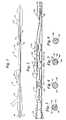
Figure 1 is a longitudinal, cross-sectional view of an angioplasty balloon catheter having a distal guide wire lumen and a movable stiffening element disposed within an inflation lumen (not illustrating the invention claimed);Figure 2 is a longitudinal, cross-sectional view of a proximal catheter shaft region including a stiffening element or spine wire having alternating wide and narrow regions disposed within an outer tube;Figure 3 is a transverse, cross-sectional view of one embodiment of a proximal catheter shaft taken through 3-3 inFigure 2 , having a tri-lobed profile;Figure 4 is a transverse, cross-sectional view of another embodiment of a proximal catheter shaft having a bi-lobed or hour-glass profile;Figure 5 is a transverse, cross-sectional view of another embodiment of a proximal catheter; andFigure 6 is a transverse, cross-sectional view of another embodiment of a proximal catheter having a triangular profile.Figure 1 illustrates a single operator exchange balloon angioplasty catheter 20. Catheter 20 includes generally aproximal region 22, adistal region 24, amanifold 26, a proximalouter tube 28 coupled tomanifold 26, a distalouter tube 30 coupled to proximalouter tube 28, and aninflatable balloon 34 disposed on distalouter tube 30. Catheter 20 also includes a distal inner tube 32, which is inserted into and disposed within distalouter tube 30. Distal inner tube 32 has alumen 38 within and can serve as a guide wire lumen. Proximalouter tube 28 and distalouter tube 30 have aninflation lumen 36 within, withinflation lumen 36 being in fluid communication with the interior ofballoon 34. In one embodiment, proximalouter tube 28 is formed of a relatively stiff polymeric material such as polyimide, while distal outer andinner tubes 30 and 32 are formed of polyethylene.- Disposed within
inflation lumen 36 is amovable core wire 40.Movable core wire 40 is slidably disposed within the inflation lumen in the example illustrated, allowing the core wire to extend distally to a location nearballoon 34. In a preferred embodiment, aproximal pressure seal 42 is disposed aboutcore wire 40 and secured to a proximal portion ofmanifold 26, forming a tight seal aboutcore wire 40.Pressure seal 42 can serve to maintain inflation fluid pressure withininflation lumen 36 whilecore wire 40 remains disposed within the inflation lumen. Core wire 40 is preferably tapered distally, having a smaller profile in the distal region than in the proximal region. Distally tapering the core wire can contribute to having a more flexible and smaller profile catheter in the catheter distal region. Continuously tapering the core wire over much of its length can provide increasing flexibility over much of its length.Core wire 40 preferably has a roundeddistal tip 44 or other safety tip configuration.Core wire 40 is formed of Nitinol in one embodiment, and stainless steel in another embodiment. While a metallic core wire is preferred, other embodiments have elongate stiffening elements formed of polymeric materials, which can also provide stiffness.- In use,
core wire 40 can be distally inserted within catheter 20 and catheter 20 inserted within the vasculature of a patient. In a preferred method,core wire 40 is inserted to the maximum desired distal extend prior to inserting catheter 20 within a patient. This can provide a maximum stiffness prior to inserting the catheter into the patient. The catheter can then be advanced within the patient's blood vessels. The core wire may lie within a distal portion of the catheter, initially in part to support the catheter distal region against buckling. In one method,core wire 40 is retracted relative to catheter 20 when the distal portion of the catheter is advanced into regions where greater flexibility is desired. In one method,core wire 40 is held in position while catheter 20 is advanced distally past the core wire. Even when partially proximally retracted,core wire 40 can provide pushability to the catheter, leaving only a catheter distal region without the added support of the core wire. In one method, the catheter distal portion having the core wire retracted is insinuated into vessels requiring the added flexibility of the catheter distal portion given by the core wire retraction. After the catheter distal portion is in position, the core wire can be advanced distally, providing support for further catheter advancement. This process can be repeated multiple times to properly position the catheter distal portion. - Once in position, the core wire is left in place in one embodiment, and inflation fluid injected into the inflation lumen around the core wire. In this method, the core wire can remain in place during the entire angioplasty procedure. In another method, the core wire can be removed substantially or entirely from the catheter prior to inflation of the balloon. In this method, the core wire can be advanced again after inflation, if desired. This method takes advantage of the fact that the added stiffening properties of the core wire may not be needed once the catheter is in position and no longer being advanced. Catheters taking advantage of this fact may be constructed having thinner walls and smaller profiles. In particular, catheters may be constructed incorporating the present invention which are not expected to be advanceable within the vasculature without the aid of an inserted core wise.
- Referring now to
Figure 2 , acatheter 120 according to the invention is illustrated, including aproximal region 122 having aproximal shaft region 124.Catheter 120 includes aproximal manifold 126 and a distalguide wire tube 128.Proximal shaft 124 includes anouter tube 130 having aninner wall 131 containing an inner stiffening element or spine wire 132. In one embodiment, spine wire 132 includes an elongatedistal portion 133, which can extend into a distal portion of the catheter. In the embodiment illustrated, spine wiredistal portion 133 is distally tapered and extends nearguide wire tube 128. Spine wire 132 can include a plurality of narrow regions, such as 134 and 136, and a plurality of wide regions or segments 138 and 140. In an alternate embodiment, the Spine wire has essentially a single wide segment such as wide segment 138, with no interspersed narrow segments. The terms "narrow" and "wide" refer generally to the maximum spine wire extent when viewed in transverse cross section. The spine wire narrow regions typically have a smaller cross-sectional profile or cross-sectional area relative to the wide regions. The wide regions can approach and typically are in contact with outer tube insidewall 131. The wide regions provide stiffness and support to the catheter shaft while the narrow regions provide flexibility. - Wide regions are separated by an inter-segment distance as indicated at "D1". D1 is a measure of the inter-segment distance measured from segment center-to-center. The inter-segment distance can also be measured by the length of the narrow region separating the wide regions, as indicated at "D2". The degree of stiffness of the shaft can be increased both by increasing the length of the wide regions and by decreasing the inter-segment distance between wide regions. In one embodiment, both the wide region length and the inter-segment distance are substantially constant over the shaft length. In another embodiment, the wide region length remains substantially constant while the inter-segment distance increases distally over a substantial portion of the shaft length. Increasing the inter-segment distance distally can provide increasing flexibility distally over the shaft length. In yet another embodiment, the wide region length is decreased distally. In still another embodiment, inter-segment distance is increased distally and wide region length is decreased distally, providing distally increasing flexibility. In some embodiments,
proximal shaft 124 includes open orun-occluded regions Open regions - Referring now to
Figure 3 , onewide region 150 is illustrated in transverse cross section.Wide region 150 has threelobes 152 creating a tri-lobed profile contactingouter tube 130 in three locations. An open area throughwide region 150 is formed by three openings orapertures 146 through the body of the spine wire. As used herein, apertures refer to openings either around or through the wide regions of the spine wire relative to what could otherwise be a solid, circular central member occluding the lumen of the outer tube. The outer extent oflobes 152 can provide stiffness or rigidity where contactingouter tube 130. - Referring now to
Figures 4-6 , other shaped wide regions are illustrated.Figure 4 illustrates a wide region having a bi-lobed or hour-glass profile 154 and twoapertures 156 through the wide region.Figure 5 illustrates anotherprofile 162 including acentral member 164 andperipheral members 166 attached thereto.Peripheral members 166 form a series ofapertures 168 between the members.Figure 6 illustrates atriangular profile 158 having threeapertures 160 allowing fluid flow past the spine wire wide regions. - The spine wire or stiffening member, such as member 132 in
Figure 2 , can be manufactured using various techniques. In one method, a metallic wire is drawn through a releasable die for a length corresponding to the length of the narrow segment. The die is released or opened, a wide segment allowed to pass, the die closed again, and the next narrow segment formed by drawing through the die. To provide for fluid flow through the final shaft product, the wide segments can be formed in non-circular shapes or in less than perfect circular shapes. To form these non-circular shapes, the wire stock used initially can have a non-circular shape such as a triangle, a bi-lobed hourglass shape, tri-lobed shape, or a generally fluted outer surface. The wire stock can be drawn through a circular die to form the narrow sections, and the die released, allowing the non-circular shapes to retain shapes related to the original shapes. - In another method, the stiffening element can be manufactured by centerless grinding. Portions of the wire corresponding to the narrow segments can be ground down to the desired width or diameter. In this method, the beginning stock can have a non-circular shape, for example, the triangular, bi-lobed, or tri-lobed shapes previously mentioned. In yet another method, a central core element can be used to form the narrow regions and separate elements affixed to the central member to form the wide regions. For example, elements having central apertures can have non-circular shapes slip fit over the central member and further secured. For example, individual pieces or members can be affixed to the central element, thereby creating a wide element, leaving apertures or passages through the wide element.
Figure 5 illustrates one embodiment including a central element having peripheral members disposed about the central element which applicants believe suitable for manufacture by affixing members about a central core wire. - Numerous characteristics and advantages of the invention covered by this document have been set forth in the foregoing description. It will be understood, however, that this disclosure is, in many respects, only illustrative. Changes may be made in details, particularly in matters of shape, size and ordering of steps without exceeding the scope of the invention. The invention's scope is, of course, defined in the language in which the appended claims are expressed.
Claims (6)
- A catheter (120) comprising a proximal tubular catheter shaft region (124), with an outer tube (130) having a lumen therethrough, and
a distal guide wire tube (128) proximate to said outer tube lumen, defining a guide wire lumen having a proximal guide wire port, an elongate stiffening member (132) is disposed within said lumen, and the elongate stiffening member extending distally beyond the proximal guide wire port,
characterised in that said stiffening member (132) includes a plurality of alternating wide (138, 140) and narrow (134, 136) segments, said segments having a cross-sectional area, wherein said wide segments (138, 140) have a larger cross-sectional area than said narrow segments (134, 136). - A tubular catheter shaft (120) as recited in claim 1, wherein said elongate stiffening member (132) has a proximal end, a distal end (133), and said wide segments (138, 140) have an inter-segment distance (D1) therebetween and said inter-segment distance (D1) is generally distally increasing, such that said shaft flexibility is generally distally increasing.
- A tubular catheter shaft (120) as recited in claim 1 or 2, wherein said wide segments have a cross-sectional profile not completely occluding said outer tube lumen, such that fluid flow through said plurality of wide segments (138, 140) within said outer tube (130) is possible.
- A tubular catheter shaft (120) as recited in claims 1 to 3, wherein said wide segment cross-sectional profiles have at least one aperture (146, 156, 168, 160) therethrough, such that fluid flow is possible through said segment within said outer tube.
- A tubular catheter shaft (120) as recited in claims 1 to 4, wherein said wide segment cross-sectional profiles have at least two apertures (146, 156, 168, 160) therethrough.
- A tubular catheter shaft (120) as recited in claim 1 to 5, wherein at least one wide segment has a cross-sectional profile with a maximum extent in close proximity to said outer tube (130), wherein said cross-sectional profile does not completely occlude said outer tube lumen and has at least one reduced diameter portion which may act as aperture (146, 156, 168, 160) therethrough, such that fluid flow through said wide segment (138) within said outer tube (130) is possible.
Applications Claiming Priority (3)
| Application Number | Priority Date | Filing Date | Title |
|---|---|---|---|
| US20833598A | 1998-12-09 | 1998-12-09 | |
| US208335 | 1998-12-09 | ||
| PCT/US1999/029344WO2000033910A1 (en) | 1998-12-09 | 1999-12-09 | Catheter having improved flexibility control |
Publications (2)
| Publication Number | Publication Date |
|---|---|
| EP1137455A1 EP1137455A1 (en) | 2001-10-04 |
| EP1137455B1true EP1137455B1 (en) | 2008-05-21 |
Family
ID=22774204
Family Applications (1)
| Application Number | Title | Priority Date | Filing Date |
|---|---|---|---|
| EP99965209AExpired - LifetimeEP1137455B1 (en) | 1998-12-09 | 1999-12-09 | Catheter having improved flexibility control |
Country Status (6)
| Country | Link |
|---|---|
| US (1) | US6712807B2 (en) |
| EP (1) | EP1137455B1 (en) |
| AT (1) | ATE395946T1 (en) |
| DE (1) | DE69938790D1 (en) |
| ES (1) | ES2308854T3 (en) |
| WO (1) | WO2000033910A1 (en) |
Families Citing this family (23)
| Publication number | Priority date | Publication date | Assignee | Title |
|---|---|---|---|---|
| US20020007145A1 (en) | 1998-10-23 | 2002-01-17 | Timothy Stivland | Catheter having improved bonding region |
| US6475184B1 (en) | 2000-06-14 | 2002-11-05 | Scimed Life Systems, Inc. | Catheter shaft |
| US6585641B1 (en) | 2000-11-02 | 2003-07-01 | Ge Medical Systems Global Technology Company, Llc | Transesophageal probe with variable stiffness |
| US20040236366A1 (en)* | 2002-05-16 | 2004-11-25 | Kennedy Kenneth C. | Non-buckling balloon catheter |
| US20030236495A1 (en)* | 2002-05-16 | 2003-12-25 | Kennedy Kenneth C. | Non-buckling balloon catheter |
| DE60325900D1 (en)* | 2003-03-18 | 2009-03-05 | Abbott Lab Vascular Entpr Ltd | |
| US7018358B2 (en)* | 2003-03-18 | 2006-03-28 | Abbott Laboratories Vascular Enterprises Limited | Catheter having an auxiliary lumen for use with a functional measurement wire |
| JP3894224B2 (en)* | 2003-11-07 | 2007-03-14 | 株式会社カネカ | Suction catheter |
| US8048028B2 (en)* | 2005-02-17 | 2011-11-01 | Boston Scientific Scimed, Inc. | Reinforced medical balloon |
| US20060182873A1 (en)* | 2005-02-17 | 2006-08-17 | Klisch Leo M | Medical devices |
| US7778684B2 (en)* | 2005-08-08 | 2010-08-17 | Boston Scientific Scimed, Inc. | MRI resonator system with stent implant |
| US8235969B2 (en)* | 2006-03-06 | 2012-08-07 | Boston Scientific Scimed, Inc. | Medical device shaft designs |
| US20070239256A1 (en)* | 2006-03-22 | 2007-10-11 | Jan Weber | Medical devices having electrical circuits with multilayer regions |
| US8574219B2 (en)* | 2006-09-18 | 2013-11-05 | Boston Scientific Scimed, Inc. | Catheter shaft including a metallic tapered region |
| US20080306441A1 (en)* | 2007-04-10 | 2008-12-11 | Wilson-Cook Medical Inc. | Non-buckling balloon catheter with spring loaded floating flexible tip |
| US8177753B2 (en)* | 2007-06-01 | 2012-05-15 | Arrow International, Inc. | Catheter insertion assembly |
| JP5626731B2 (en) | 2011-03-04 | 2014-11-19 | 朝日インテック株式会社 | Balloon catheter |
| US10722683B2 (en)* | 2011-04-05 | 2020-07-28 | Thermopeutix, Inc. | Microcatheter with distal tip portion and proximal solution lumen |
| US20130096482A1 (en)* | 2011-10-18 | 2013-04-18 | Medtronic Xomed, Inc. | Alternate geometry stylet for ventricular shunt catheter placement |
| US20140142506A1 (en)* | 2012-11-16 | 2014-05-22 | Boston Scientific Scimed, Inc. | Balloon catheter with improved pushability |
| CA2946324C (en) | 2014-05-02 | 2023-03-21 | Intellimedical Technologies Pty Ltd | Elongate steerable devices for insertion into a subject's body |
| US20230191078A1 (en)* | 2020-05-27 | 2023-06-22 | Hollister Incorporated | Multi-flex urinary catheter |
| US20240009430A1 (en)* | 2022-07-08 | 2024-01-11 | Abbott Cardiovascular Systems Inc. | Guidewire core having non-round cross-sections |
Family Cites Families (76)
| Publication number | Priority date | Publication date | Assignee | Title |
|---|---|---|---|---|
| US2687131A (en) | 1952-09-17 | 1954-08-24 | Davol Rubber Co | Female incontinence catheter |
| US2936760A (en) | 1956-09-10 | 1960-05-17 | Davol Rubber Co | Positive pressure catheter |
| US3225762A (en) | 1963-10-25 | 1965-12-28 | Yolan R Guttman | Intravenous stylet catheter |
| US3884242A (en) | 1971-03-29 | 1975-05-20 | Mpc Kurgisil | Catheter assembly |
| SU627828A1 (en) | 1975-08-06 | 1978-10-15 | Borisenko Valentin A | Catheter |
| US4044765A (en) | 1975-12-17 | 1977-08-30 | Medical Evaluation Devices And Instruments Corporation | Flexible tube for intra-venous feeding |
| DE2828447C2 (en) | 1978-06-29 | 1980-05-14 | Willy Ruesch Gmbh & Co Kg, 7053 Kernen | Laryngeal tube |
| US4468224A (en) | 1982-01-28 | 1984-08-28 | Advanced Cardiovascular Systems, Inc. | System and method for catheter placement in blood vessels of a human patient |
| US4662368A (en) | 1983-06-13 | 1987-05-05 | Trimedyne Laser Systems, Inc. | Localized heat applying medical device |
| US4705507A (en) | 1984-05-02 | 1987-11-10 | Boyles Paul W | Arterial catheter means |
| SU1251914A1 (en) | 1984-05-04 | 1986-08-23 | Челябинский государственный институт по проектированию металлургических заводов "Челябгипромез" | Pneumatic cardiodilator |
| US4597755A (en) | 1984-05-30 | 1986-07-01 | Advanced Cardiovascular Systems, Inc. | Large bore catheter having flexible tip construction |
| DE3442736C2 (en) | 1984-11-23 | 1987-03-05 | Tassilo Dr.med. 7800 Freiburg Bonzel | Dilatation catheter |
| US4917088A (en) | 1985-05-02 | 1990-04-17 | C. R. Bard, Inc. | Balloon dilation probe |
| US5102390A (en) | 1985-05-02 | 1992-04-07 | C. R. Bard, Inc. | Microdilatation probe and system for performing angioplasty in highly stenosed blood vessels |
| US4601713A (en)* | 1985-06-11 | 1986-07-22 | Genus Catheter Technologies, Inc. | Variable diameter catheter |
| US5449343A (en) | 1985-07-30 | 1995-09-12 | Advanced Cardiovascular Systems, Inc. | Steerable dilatation catheter |
| US5040548A (en) | 1989-06-01 | 1991-08-20 | Yock Paul G | Angioplasty mehtod |
| US5061273A (en) | 1989-06-01 | 1991-10-29 | Yock Paul G | Angioplasty apparatus facilitating rapid exchanges |
| US4798598A (en) | 1986-05-23 | 1989-01-17 | Sarcem S.A. | Guide for a catheter |
| US4846174A (en) | 1986-08-08 | 1989-07-11 | Scimed Life Systems, Inc. | Angioplasty dilating guide wire |
| US4719924A (en) | 1986-09-09 | 1988-01-19 | C. R. Bard, Inc. | Small diameter steerable guidewire with adjustable tip |
| US4976720A (en) | 1987-01-06 | 1990-12-11 | Advanced Cardiovascular Systems, Inc. | Vascular catheters |
| US4748982A (en) | 1987-01-06 | 1988-06-07 | Advanced Cardiovascular Systems, Inc. | Reinforced balloon dilatation catheter with slitted exchange sleeve and method |
| US4771777A (en) | 1987-01-06 | 1988-09-20 | Advanced Cardiovascular Systems, Inc. | Perfusion type balloon dilatation catheter, apparatus and method |
| US4988356A (en) | 1987-02-27 | 1991-01-29 | C. R. Bard, Inc. | Catheter and guidewire exchange system |
| US4824435A (en) | 1987-05-18 | 1989-04-25 | Thomas J. Fogarty | Instrument guidance system |
| US4820349A (en) | 1987-08-21 | 1989-04-11 | C. R. Bard, Inc. | Dilatation catheter with collapsible outer diameter |
| US4881547A (en) | 1987-08-31 | 1989-11-21 | Danforth John W | Angioplasty dilitation balloon catheter |
| US4953553A (en) | 1989-05-11 | 1990-09-04 | Advanced Cardiovascular Systems, Inc. | Pressure monitoring guidewire with a flexible distal portion |
| US5050606A (en) | 1987-09-30 | 1991-09-24 | Advanced Cardiovascular Systems, Inc. | Method for measuring pressure within a patient's coronary artery |
| US4906241A (en) | 1987-11-30 | 1990-03-06 | Boston Scientific Corporation | Dilation balloon |
| JPH01145074A (en) | 1987-12-01 | 1989-06-07 | Terumo Corp | Balloon catheter |
| US4921478A (en) | 1988-02-23 | 1990-05-01 | C. R. Bard, Inc. | Cerebral balloon angioplasty system |
| US5425711A (en) | 1988-02-29 | 1995-06-20 | Scimed Life Systems, Inc. | Intravascular catheter with distal guide wire lumen and transition member |
| US5156594A (en) | 1990-08-28 | 1992-10-20 | Scimed Life Systems, Inc. | Balloon catheter with distal guide wire lumen |
| US4943278A (en) | 1988-02-29 | 1990-07-24 | Scimed Life Systems, Inc. | Dilatation balloon catheter |
| US4944745A (en) | 1988-02-29 | 1990-07-31 | Scimed Life Systems, Inc. | Perfusion balloon catheter |
| US4838268A (en) | 1988-03-07 | 1989-06-13 | Scimed Life Systems, Inc. | Non-over-the wire balloon catheter |
| US4896670A (en) | 1988-04-19 | 1990-01-30 | C. R. Bard, Inc. | Kissing balloon catheter |
| US4998917A (en) | 1988-05-26 | 1991-03-12 | Advanced Cardiovascular Systems, Inc. | High torque steerable dilatation catheter |
| US4940062A (en) | 1988-05-26 | 1990-07-10 | Advanced Cardiovascular Systems, Inc. | Guiding member with deflectable tip |
| EP0344530A1 (en) | 1988-05-27 | 1989-12-06 | Advanced Cardiovascular Systems, Inc. | Vascular catheter assembly with a guiding sleeve |
| US4877031A (en) | 1988-07-22 | 1989-10-31 | Advanced Cardiovascular Systems, Inc. | Steerable perfusion dilatation catheter |
| US4998923A (en) | 1988-08-11 | 1991-03-12 | Advanced Cardiovascular Systems, Inc. | Steerable dilatation catheter |
| ES2064416T3 (en) | 1988-10-20 | 1995-02-01 | Terumo Corp | CATHETER GIVEN WITH AN EXPANDABLE ELEMENT AND MANUFACTURING METHOD THEREOF. |
| FR2638364A1 (en) | 1988-10-27 | 1990-05-04 | Farcot Jean Christian | APPARATUS FOR PERFORMING PROLONGED ANGIOPLASTY |
| MY104678A (en) | 1988-11-10 | 1994-05-31 | Bard Inc C R | Balloon dilatation catheter with integral guidewire. |
| US5035705A (en) | 1989-01-13 | 1991-07-30 | Scimed Life Systems, Inc. | Method of purging a balloon catheter |
| US5032113A (en) | 1989-04-13 | 1991-07-16 | Scimed Life Systems, Inc. | Innerless catheter |
| US5035686A (en) | 1989-01-27 | 1991-07-30 | C. R. Bard, Inc. | Catheter exchange system with detachable luer fitting |
| ES2049204T3 (en) | 1989-01-30 | 1994-07-16 | Bard Inc C R | RAPIDLY CHANGEABLE CORONARY CATHETER. |
| US5728067A (en) | 1989-01-30 | 1998-03-17 | C. R. Bard, Inc. | Rapidly exchangeable coronary catheter |
| US4946466A (en) | 1989-03-03 | 1990-08-07 | Cordis Corporation | Transluminal angioplasty apparatus |
| US4928693A (en) | 1989-03-13 | 1990-05-29 | Schneider (Usa), Inc. | Pressure monitor catheter |
| US5112304A (en) | 1989-03-17 | 1992-05-12 | Angeion Corporation | Balloon catheter |
| US5047045A (en) | 1989-04-13 | 1991-09-10 | Scimed Life Systems, Inc. | Multi-section coaxial angioplasty catheter |
| US5042985A (en) | 1989-05-11 | 1991-08-27 | Advanced Cardiovascular Systems, Inc. | Dilatation catheter suitable for peripheral arteries |
| US4976690A (en) | 1989-08-10 | 1990-12-11 | Scimed Life Systems, Inc. | Variable stiffness angioplasty catheter |
| US5180367A (en) | 1989-09-06 | 1993-01-19 | Datascope Corporation | Procedure and balloon catheter system for relieving arterial or veinal restrictions without exchanging balloon catheters |
| US5034001A (en) | 1989-09-08 | 1991-07-23 | Advanced Cardiovascular Systems, Inc. | Method of repairing a damaged blood vessel with an expandable cage catheter |
| US5169386A (en) | 1989-09-11 | 1992-12-08 | Bruce B. Becker | Method and catheter for dilatation of the lacrimal system |
| US5176637A (en) | 1990-04-19 | 1993-01-05 | Terumo Kabushiki Kaisha | Catheter equipped with a dilation element |
| US5102403A (en) | 1990-06-18 | 1992-04-07 | Eckhard Alt | Therapeutic medical instrument for insertion into body |
| US5217482A (en) | 1990-08-28 | 1993-06-08 | Scimed Life Systems, Inc. | Balloon catheter with distal guide wire lumen |
| US5395332A (en) | 1990-08-28 | 1995-03-07 | Scimed Life Systems, Inc. | Intravascualr catheter with distal tip guide wire lumen |
| US5154725A (en) | 1991-06-07 | 1992-10-13 | Advanced Cardiovascular Systems, Inc. | Easily exchangeable catheter system |
| US5242396A (en) | 1991-12-19 | 1993-09-07 | Advanced Cardiovascular Systems, Inc. | Dilatation catheter with reinforcing mandrel |
| US5382238A (en)* | 1993-05-20 | 1995-01-17 | Quinton Instrument Company | Catheter stiffeners |
| US5336184A (en)* | 1993-07-15 | 1994-08-09 | Teirstein Paul S | Rapid exchange catheter |
| US5545138A (en)* | 1994-02-28 | 1996-08-13 | Medtronic, Inc. | Adjustable stiffness dilatation catheter |
| EP0749333A1 (en)* | 1994-03-10 | 1996-12-27 | Schneider (Usa) Inc. | Catheter having shaft of varying stiffness |
| US5643209A (en) | 1995-12-15 | 1997-07-01 | Medtronic, Inc. | High pressure balloon tip |
| US5807328A (en)* | 1996-04-01 | 1998-09-15 | Medtronic, Inc. | Balloon catheter assembly with selectively occluded and vented lumen |
| NL1004102C2 (en)* | 1996-09-24 | 1998-03-26 | Cordis Europ | Catheter. |
| US6475187B1 (en)* | 1998-03-04 | 2002-11-05 | Scimed Life Systems, Inc. | Convertible catheter incorporating distal force transfer mechanism |
- 1999
- 1999-12-09DEDE69938790Tpatent/DE69938790D1/ennot_activeExpired - Lifetime
- 1999-12-09ATAT99965209Tpatent/ATE395946T1/ennot_activeIP Right Cessation
- 1999-12-09ESES99965209Tpatent/ES2308854T3/ennot_activeExpired - Lifetime
- 1999-12-09WOPCT/US1999/029344patent/WO2000033910A1/enactiveApplication Filing
- 1999-12-09EPEP99965209Apatent/EP1137455B1/ennot_activeExpired - Lifetime
- 2002
- 2002-02-28USUS10/087,338patent/US6712807B2/ennot_activeExpired - Fee Related
Also Published As
| Publication number | Publication date |
|---|---|
| ES2308854T3 (en) | 2008-12-01 |
| US20020128596A1 (en) | 2002-09-12 |
| ATE395946T1 (en) | 2008-06-15 |
| US6712807B2 (en) | 2004-03-30 |
| EP1137455A1 (en) | 2001-10-04 |
| WO2000033910A1 (en) | 2000-06-15 |
| DE69938790D1 (en) | 2008-07-03 |
Similar Documents
| Publication | Publication Date | Title |
|---|---|---|
| EP1137455B1 (en) | Catheter having improved flexibility control | |
| US5891056A (en) | Guidewire replacement device with flexible intermediate section | |
| US6364894B1 (en) | Method of making an angioplasty balloon catheter | |
| US6923788B2 (en) | Catheter having a low-friction guidewire lumen and method of manufacture | |
| EP1490141B1 (en) | Catheter and guide wire exchange system | |
| US5334154A (en) | Perfusion type dilatation catheter having perfusion ports with depressed proximal edges | |
| USRE36857E (en) | Interlocking peel-away dilation catheter | |
| US5160321A (en) | Balloon catheters | |
| US5090958A (en) | Balloon catheters | |
| EP2099516B2 (en) | Rapid-exchange balloon catheter shaft | |
| EP0715531B1 (en) | Dilatation catheter with eccentric balloon | |
| US5346505A (en) | Easily exchangeable catheter system | |
| US5147377A (en) | Balloon catheters | |
| US6196995B1 (en) | Reinforced edge exchange catheter | |
| EP0973576B1 (en) | Catheter with removable balloon protector and stent delivery system with removable stent protector | |
| US4983167A (en) | Balloon catheters | |
| CA2070914C (en) | Dilatation catheter and guidewire exchange | |
| WO1997033642A9 (en) | Guidewire replacement device with flexible intermediate section | |
| EP1391217A1 (en) | Over-the-wire catheter having a slidable instrument for gripping a guidewire | |
| JPH0626576B2 (en) | Device for performing angiogenesis | |
| EP1518582B1 (en) | Rapid-exchange balloon catheter with hypotube shaft | |
| IES83263Y1 (en) | Catheter and guide wire exchange system |
Legal Events
| Date | Code | Title | Description |
|---|---|---|---|
| PUAI | Public reference made under article 153(3) epc to a published international application that has entered the european phase | Free format text:ORIGINAL CODE: 0009012 | |
| 17P | Request for examination filed | Effective date:20010709 | |
| AK | Designated contracting states | Kind code of ref document:A1 Designated state(s):AT BE CH CY DE DK ES FI FR GB GR IE IT LI LU MC NL PT SE | |
| RIN1 | Information on inventor provided before grant (corrected) | Inventor name:KHOURY, ELIAS, A. Inventor name:STIVLAND, TIMOTHY, M. | |
| RAP1 | Party data changed (applicant data changed or rights of an application transferred) | Owner name:BOSTON SCIENTIFIC SCIMED, INC. | |
| 17Q | First examination report despatched | Effective date:20060314 | |
| GRAP | Despatch of communication of intention to grant a patent | Free format text:ORIGINAL CODE: EPIDOSNIGR1 | |
| GRAS | Grant fee paid | Free format text:ORIGINAL CODE: EPIDOSNIGR3 | |
| GRAA | (expected) grant | Free format text:ORIGINAL CODE: 0009210 | |
| AK | Designated contracting states | Kind code of ref document:B1 Designated state(s):AT BE CH CY DE DK ES FI FR GB GR IE IT LI LU MC NL PT SE | |
| REG | Reference to a national code | Ref country code:GB Ref legal event code:FG4D | |
| REG | Reference to a national code | Ref country code:CH Ref legal event code:EP | |
| REF | Corresponds to: | Ref document number:69938790 Country of ref document:DE Date of ref document:20080703 Kind code of ref document:P | |
| REG | Reference to a national code | Ref country code:IE Ref legal event code:FG4D | |
| PG25 | Lapsed in a contracting state [announced via postgrant information from national office to epo] | Ref country code:FI Free format text:LAPSE BECAUSE OF FAILURE TO SUBMIT A TRANSLATION OF THE DESCRIPTION OR TO PAY THE FEE WITHIN THE PRESCRIBED TIME-LIMIT Effective date:20080521 | |
| PG25 | Lapsed in a contracting state [announced via postgrant information from national office to epo] | Ref country code:AT Free format text:LAPSE BECAUSE OF FAILURE TO SUBMIT A TRANSLATION OF THE DESCRIPTION OR TO PAY THE FEE WITHIN THE PRESCRIBED TIME-LIMIT Effective date:20080521 | |
| REG | Reference to a national code | Ref country code:ES Ref legal event code:FG2A Ref document number:2308854 Country of ref document:ES Kind code of ref document:T3 | |
| PG25 | Lapsed in a contracting state [announced via postgrant information from national office to epo] | Ref country code:SE Free format text:LAPSE BECAUSE OF FAILURE TO SUBMIT A TRANSLATION OF THE DESCRIPTION OR TO PAY THE FEE WITHIN THE PRESCRIBED TIME-LIMIT Effective date:20080821 Ref country code:PT Free format text:LAPSE BECAUSE OF FAILURE TO SUBMIT A TRANSLATION OF THE DESCRIPTION OR TO PAY THE FEE WITHIN THE PRESCRIBED TIME-LIMIT Effective date:20081021 Ref country code:DK Free format text:LAPSE BECAUSE OF FAILURE TO SUBMIT A TRANSLATION OF THE DESCRIPTION OR TO PAY THE FEE WITHIN THE PRESCRIBED TIME-LIMIT Effective date:20080521 | |
| PLBE | No opposition filed within time limit | Free format text:ORIGINAL CODE: 0009261 | |
| STAA | Information on the status of an ep patent application or granted ep patent | Free format text:STATUS: NO OPPOSITION FILED WITHIN TIME LIMIT | |
| 26N | No opposition filed | Effective date:20090224 | |
| PG25 | Lapsed in a contracting state [announced via postgrant information from national office to epo] | Ref country code:MC Free format text:LAPSE BECAUSE OF NON-PAYMENT OF DUE FEES Effective date:20081231 | |
| REG | Reference to a national code | Ref country code:CH Ref legal event code:PL | |
| PG25 | Lapsed in a contracting state [announced via postgrant information from national office to epo] | Ref country code:LI Free format text:LAPSE BECAUSE OF NON-PAYMENT OF DUE FEES Effective date:20081231 Ref country code:CH Free format text:LAPSE BECAUSE OF NON-PAYMENT OF DUE FEES Effective date:20081231 | |
| PG25 | Lapsed in a contracting state [announced via postgrant information from national office to epo] | Ref country code:LU Free format text:LAPSE BECAUSE OF NON-PAYMENT OF DUE FEES Effective date:20081209 | |
| PG25 | Lapsed in a contracting state [announced via postgrant information from national office to epo] | Ref country code:CY Free format text:LAPSE BECAUSE OF FAILURE TO SUBMIT A TRANSLATION OF THE DESCRIPTION OR TO PAY THE FEE WITHIN THE PRESCRIBED TIME-LIMIT Effective date:20080521 | |
| PG25 | Lapsed in a contracting state [announced via postgrant information from national office to epo] | Ref country code:GR Free format text:LAPSE BECAUSE OF FAILURE TO SUBMIT A TRANSLATION OF THE DESCRIPTION OR TO PAY THE FEE WITHIN THE PRESCRIBED TIME-LIMIT Effective date:20080822 | |
| PGFP | Annual fee paid to national office [announced via postgrant information from national office to epo] | Ref country code:FR Payment date:20101203 Year of fee payment:12 | |
| PGFP | Annual fee paid to national office [announced via postgrant information from national office to epo] | Ref country code:IT Payment date:20101215 Year of fee payment:12 Ref country code:GB Payment date:20101123 Year of fee payment:12 | |
| PGFP | Annual fee paid to national office [announced via postgrant information from national office to epo] | Ref country code:ES Payment date:20101213 Year of fee payment:12 Ref country code:BE Payment date:20101213 Year of fee payment:12 | |
| PGFP | Annual fee paid to national office [announced via postgrant information from national office to epo] | Ref country code:DE Payment date:20111230 Year of fee payment:13 | |
| BERE | Be: lapsed | Owner name:BOSTON SCIENTIFIC SCIMED, INC. Effective date:20111231 | |
| GBPC | Gb: european patent ceased through non-payment of renewal fee | Effective date:20111209 | |
| REG | Reference to a national code | Ref country code:FR Ref legal event code:ST Effective date:20120831 | |
| PG25 | Lapsed in a contracting state [announced via postgrant information from national office to epo] | Ref country code:GB Free format text:LAPSE BECAUSE OF NON-PAYMENT OF DUE FEES Effective date:20111209 Ref country code:BE Free format text:LAPSE BECAUSE OF NON-PAYMENT OF DUE FEES Effective date:20111231 | |
| PG25 | Lapsed in a contracting state [announced via postgrant information from national office to epo] | Ref country code:IT Free format text:LAPSE BECAUSE OF NON-PAYMENT OF DUE FEES Effective date:20111209 | |
| PG25 | Lapsed in a contracting state [announced via postgrant information from national office to epo] | Ref country code:FR Free format text:LAPSE BECAUSE OF NON-PAYMENT OF DUE FEES Effective date:20120102 | |
| REG | Reference to a national code | Ref country code:DE Ref legal event code:R119 Ref document number:69938790 Country of ref document:DE Effective date:20130702 | |
| REG | Reference to a national code | Ref country code:ES Ref legal event code:FD2A Effective date:20131030 | |
| PG25 | Lapsed in a contracting state [announced via postgrant information from national office to epo] | Ref country code:DE Free format text:LAPSE BECAUSE OF NON-PAYMENT OF DUE FEES Effective date:20130702 Ref country code:ES Free format text:LAPSE BECAUSE OF NON-PAYMENT OF DUE FEES Effective date:20111210 | |
| PGFP | Annual fee paid to national office [announced via postgrant information from national office to epo] | Ref country code:IE Payment date:20131210 Year of fee payment:15 | |
| PGFP | Annual fee paid to national office [announced via postgrant information from national office to epo] | Ref country code:NL Payment date:20131210 Year of fee payment:15 | |
| REG | Reference to a national code | Ref country code:NL Ref legal event code:V1 Effective date:20150701 | |
| REG | Reference to a national code | Ref country code:NL Ref legal event code:V1 Effective date:20150701 | |
| REG | Reference to a national code | Ref country code:IE Ref legal event code:MM4A | |
| PG25 | Lapsed in a contracting state [announced via postgrant information from national office to epo] | Ref country code:NL Free format text:LAPSE BECAUSE OF NON-PAYMENT OF DUE FEES Effective date:20150701 | |
| PG25 | Lapsed in a contracting state [announced via postgrant information from national office to epo] | Ref country code:IE Free format text:LAPSE BECAUSE OF NON-PAYMENT OF DUE FEES Effective date:20141209 |