EP1136685A2 - Apparatus for and method of controlling an internal combustion engine - Google Patents
Apparatus for and method of controlling an internal combustion engineDownload PDFInfo
- Publication number
- EP1136685A2 EP1136685A2EP01110090AEP01110090AEP1136685A2EP 1136685 A2EP1136685 A2EP 1136685A2EP 01110090 AEP01110090 AEP 01110090AEP 01110090 AEP01110090 AEP 01110090AEP 1136685 A2EP1136685 A2EP 1136685A2
- Authority
- EP
- European Patent Office
- Prior art keywords
- air
- fuel
- engine
- fuel ratio
- torque
- Prior art date
- Legal status (The legal status is an assumption and is not a legal conclusion. Google has not performed a legal analysis and makes no representation as to the accuracy of the status listed.)
- Granted
Links
Images


Classifications
- F—MECHANICAL ENGINEERING; LIGHTING; HEATING; WEAPONS; BLASTING
- F02—COMBUSTION ENGINES; HOT-GAS OR COMBUSTION-PRODUCT ENGINE PLANTS
- F02D—CONTROLLING COMBUSTION ENGINES
- F02D13/00—Controlling the engine output power by varying inlet or exhaust valve operating characteristics, e.g. timing
- F02D13/02—Controlling the engine output power by varying inlet or exhaust valve operating characteristics, e.g. timing during engine operation
- F02D13/0223—Variable control of the intake valves only
- F02D13/0226—Variable control of the intake valves only changing valve lift or valve lift and timing
- F02D13/023—Variable control of the intake valves only changing valve lift or valve lift and timing the change of valve timing is caused by the change in valve lift, i.e. both valve lift and timing are functionally related
- F—MECHANICAL ENGINEERING; LIGHTING; HEATING; WEAPONS; BLASTING
- F02—COMBUSTION ENGINES; HOT-GAS OR COMBUSTION-PRODUCT ENGINE PLANTS
- F02D—CONTROLLING COMBUSTION ENGINES
- F02D45/00—Electrical control not provided for in groups F02D41/00 - F02D43/00
- F—MECHANICAL ENGINEERING; LIGHTING; HEATING; WEAPONS; BLASTING
- F01—MACHINES OR ENGINES IN GENERAL; ENGINE PLANTS IN GENERAL; STEAM ENGINES
- F01L—CYCLICALLY OPERATING VALVES FOR MACHINES OR ENGINES
- F01L1/00—Valve-gear or valve arrangements, e.g. lift-valve gear
- F01L1/26—Valve-gear or valve arrangements, e.g. lift-valve gear characterised by the provision of two or more valves operated simultaneously by same transmitting-gear; peculiar to machines or engines with more than two lift-valves per cylinder
- F01L1/267—Valve-gear or valve arrangements, e.g. lift-valve gear characterised by the provision of two or more valves operated simultaneously by same transmitting-gear; peculiar to machines or engines with more than two lift-valves per cylinder with means for varying the timing or the lift of the valves
- F—MECHANICAL ENGINEERING; LIGHTING; HEATING; WEAPONS; BLASTING
- F01—MACHINES OR ENGINES IN GENERAL; ENGINE PLANTS IN GENERAL; STEAM ENGINES
- F01L—CYCLICALLY OPERATING VALVES FOR MACHINES OR ENGINES
- F01L13/00—Modifications of valve-gear to facilitate reversing, braking, starting, changing compression ratio, or other specific operations
- F01L13/0015—Modifications of valve-gear to facilitate reversing, braking, starting, changing compression ratio, or other specific operations for optimising engine performances by modifying valve lift according to various working parameters, e.g. rotational speed, load, torque
- F01L13/0036—Modifications of valve-gear to facilitate reversing, braking, starting, changing compression ratio, or other specific operations for optimising engine performances by modifying valve lift according to various working parameters, e.g. rotational speed, load, torque the valves being driven by two or more cams with different shape, size or timing or a single cam profiled in axial and radial direction
- F—MECHANICAL ENGINEERING; LIGHTING; HEATING; WEAPONS; BLASTING
- F01—MACHINES OR ENGINES IN GENERAL; ENGINE PLANTS IN GENERAL; STEAM ENGINES
- F01L—CYCLICALLY OPERATING VALVES FOR MACHINES OR ENGINES
- F01L9/00—Valve-gear or valve arrangements actuated non-mechanically
- F01L9/20—Valve-gear or valve arrangements actuated non-mechanically by electric means
- F—MECHANICAL ENGINEERING; LIGHTING; HEATING; WEAPONS; BLASTING
- F02—COMBUSTION ENGINES; HOT-GAS OR COMBUSTION-PRODUCT ENGINE PLANTS
- F02B—INTERNAL-COMBUSTION PISTON ENGINES; COMBUSTION ENGINES IN GENERAL
- F02B17/00—Engines characterised by means for effecting stratification of charge in cylinders
- F02B17/005—Engines characterised by means for effecting stratification of charge in cylinders having direct injection in the combustion chamber
- F—MECHANICAL ENGINEERING; LIGHTING; HEATING; WEAPONS; BLASTING
- F02—COMBUSTION ENGINES; HOT-GAS OR COMBUSTION-PRODUCT ENGINE PLANTS
- F02B—INTERNAL-COMBUSTION PISTON ENGINES; COMBUSTION ENGINES IN GENERAL
- F02B19/00—Engines characterised by precombustion chambers
- F02B19/12—Engines characterised by precombustion chambers with positive ignition
- F—MECHANICAL ENGINEERING; LIGHTING; HEATING; WEAPONS; BLASTING
- F02—COMBUSTION ENGINES; HOT-GAS OR COMBUSTION-PRODUCT ENGINE PLANTS
- F02B—INTERNAL-COMBUSTION PISTON ENGINES; COMBUSTION ENGINES IN GENERAL
- F02B23/00—Other engines characterised by special shape or construction of combustion chambers to improve operation
- F02B23/08—Other engines characterised by special shape or construction of combustion chambers to improve operation with positive ignition
- F02B23/10—Other engines characterised by special shape or construction of combustion chambers to improve operation with positive ignition with separate admission of air and fuel into cylinder
- F02B23/101—Other engines characterised by special shape or construction of combustion chambers to improve operation with positive ignition with separate admission of air and fuel into cylinder the injector being placed on or close to the cylinder centre axis, e.g. with mixture formation using spray guided concepts
- F—MECHANICAL ENGINEERING; LIGHTING; HEATING; WEAPONS; BLASTING
- F02—COMBUSTION ENGINES; HOT-GAS OR COMBUSTION-PRODUCT ENGINE PLANTS
- F02D—CONTROLLING COMBUSTION ENGINES
- F02D11/00—Arrangements for, or adaptations to, non-automatic engine control initiation means, e.g. operator initiated
- F02D11/06—Arrangements for, or adaptations to, non-automatic engine control initiation means, e.g. operator initiated characterised by non-mechanical control linkages, e.g. fluid control linkages or by control linkages with power drive or assistance
- F02D11/10—Arrangements for, or adaptations to, non-automatic engine control initiation means, e.g. operator initiated characterised by non-mechanical control linkages, e.g. fluid control linkages or by control linkages with power drive or assistance of the electric type
- F02D11/105—Arrangements for, or adaptations to, non-automatic engine control initiation means, e.g. operator initiated characterised by non-mechanical control linkages, e.g. fluid control linkages or by control linkages with power drive or assistance of the electric type characterised by the function converting demand to actuation, e.g. a map indicating relations between an accelerator pedal position and throttle valve opening or target engine torque
- F—MECHANICAL ENGINEERING; LIGHTING; HEATING; WEAPONS; BLASTING
- F02—COMBUSTION ENGINES; HOT-GAS OR COMBUSTION-PRODUCT ENGINE PLANTS
- F02D—CONTROLLING COMBUSTION ENGINES
- F02D13/00—Controlling the engine output power by varying inlet or exhaust valve operating characteristics, e.g. timing
- F02D13/02—Controlling the engine output power by varying inlet or exhaust valve operating characteristics, e.g. timing during engine operation
- F02D13/0261—Controlling the valve overlap
- F—MECHANICAL ENGINEERING; LIGHTING; HEATING; WEAPONS; BLASTING
- F02—COMBUSTION ENGINES; HOT-GAS OR COMBUSTION-PRODUCT ENGINE PLANTS
- F02D—CONTROLLING COMBUSTION ENGINES
- F02D29/00—Controlling engines, such controlling being peculiar to the devices driven thereby, the devices being other than parts or accessories essential to engine operation, e.g. controlling of engines by signals external thereto
- F02D29/02—Controlling engines, such controlling being peculiar to the devices driven thereby, the devices being other than parts or accessories essential to engine operation, e.g. controlling of engines by signals external thereto peculiar to engines driving vehicles; peculiar to engines driving variable pitch propellers
- F—MECHANICAL ENGINEERING; LIGHTING; HEATING; WEAPONS; BLASTING
- F02—COMBUSTION ENGINES; HOT-GAS OR COMBUSTION-PRODUCT ENGINE PLANTS
- F02D—CONTROLLING COMBUSTION ENGINES
- F02D33/00—Controlling delivery of fuel or combustion-air, not otherwise provided for
- F—MECHANICAL ENGINEERING; LIGHTING; HEATING; WEAPONS; BLASTING
- F02—COMBUSTION ENGINES; HOT-GAS OR COMBUSTION-PRODUCT ENGINE PLANTS
- F02D—CONTROLLING COMBUSTION ENGINES
- F02D35/00—Controlling engines, dependent on conditions exterior or interior to engines, not otherwise provided for
- F02D35/02—Controlling engines, dependent on conditions exterior or interior to engines, not otherwise provided for on interior conditions
- F02D35/023—Controlling engines, dependent on conditions exterior or interior to engines, not otherwise provided for on interior conditions by determining the cylinder pressure
- F—MECHANICAL ENGINEERING; LIGHTING; HEATING; WEAPONS; BLASTING
- F02—COMBUSTION ENGINES; HOT-GAS OR COMBUSTION-PRODUCT ENGINE PLANTS
- F02D—CONTROLLING COMBUSTION ENGINES
- F02D37/00—Non-electrical conjoint control of two or more functions of engines, not otherwise provided for
- F02D37/02—Non-electrical conjoint control of two or more functions of engines, not otherwise provided for one of the functions being ignition
- F—MECHANICAL ENGINEERING; LIGHTING; HEATING; WEAPONS; BLASTING
- F02—COMBUSTION ENGINES; HOT-GAS OR COMBUSTION-PRODUCT ENGINE PLANTS
- F02D—CONTROLLING COMBUSTION ENGINES
- F02D41/00—Electrical control of supply of combustible mixture or its constituents
- F02D41/02—Circuit arrangements for generating control signals
- F02D41/021—Introducing corrections for particular conditions exterior to the engine
- F02D41/0215—Introducing corrections for particular conditions exterior to the engine in relation with elements of the transmission
- F02D41/0225—Introducing corrections for particular conditions exterior to the engine in relation with elements of the transmission in relation with the gear ratio or shift lever position
- F—MECHANICAL ENGINEERING; LIGHTING; HEATING; WEAPONS; BLASTING
- F02—COMBUSTION ENGINES; HOT-GAS OR COMBUSTION-PRODUCT ENGINE PLANTS
- F02D—CONTROLLING COMBUSTION ENGINES
- F02D41/00—Electrical control of supply of combustible mixture or its constituents
- F02D41/02—Circuit arrangements for generating control signals
- F02D41/021—Introducing corrections for particular conditions exterior to the engine
- F02D41/0215—Introducing corrections for particular conditions exterior to the engine in relation with elements of the transmission
- F02D41/023—Introducing corrections for particular conditions exterior to the engine in relation with elements of the transmission in relation with the gear ratio shifting
- F—MECHANICAL ENGINEERING; LIGHTING; HEATING; WEAPONS; BLASTING
- F02—COMBUSTION ENGINES; HOT-GAS OR COMBUSTION-PRODUCT ENGINE PLANTS
- F02D—CONTROLLING COMBUSTION ENGINES
- F02D41/00—Electrical control of supply of combustible mixture or its constituents
- F02D41/02—Circuit arrangements for generating control signals
- F02D41/14—Introducing closed-loop corrections
- F02D41/1438—Introducing closed-loop corrections using means for determining characteristics of the combustion gases; Sensors therefor
- F02D41/1473—Introducing closed-loop corrections using means for determining characteristics of the combustion gases; Sensors therefor characterised by the regulation method
- F02D41/1475—Regulating the air fuel ratio at a value other than stoichiometry
- F—MECHANICAL ENGINEERING; LIGHTING; HEATING; WEAPONS; BLASTING
- F02—COMBUSTION ENGINES; HOT-GAS OR COMBUSTION-PRODUCT ENGINE PLANTS
- F02D—CONTROLLING COMBUSTION ENGINES
- F02D41/00—Electrical control of supply of combustible mixture or its constituents
- F02D41/02—Circuit arrangements for generating control signals
- F02D41/14—Introducing closed-loop corrections
- F02D41/1438—Introducing closed-loop corrections using means for determining characteristics of the combustion gases; Sensors therefor
- F02D41/1486—Introducing closed-loop corrections using means for determining characteristics of the combustion gases; Sensors therefor with correction for particular operating conditions
- F02D41/1488—Inhibiting the regulation
- F02D41/149—Replacing of the control value by an other parameter
- F—MECHANICAL ENGINEERING; LIGHTING; HEATING; WEAPONS; BLASTING
- F02—COMBUSTION ENGINES; HOT-GAS OR COMBUSTION-PRODUCT ENGINE PLANTS
- F02D—CONTROLLING COMBUSTION ENGINES
- F02D41/00—Electrical control of supply of combustible mixture or its constituents
- F02D41/02—Circuit arrangements for generating control signals
- F02D41/14—Introducing closed-loop corrections
- F02D41/1497—With detection of the mechanical response of the engine
- F—MECHANICAL ENGINEERING; LIGHTING; HEATING; WEAPONS; BLASTING
- F02—COMBUSTION ENGINES; HOT-GAS OR COMBUSTION-PRODUCT ENGINE PLANTS
- F02D—CONTROLLING COMBUSTION ENGINES
- F02D41/00—Electrical control of supply of combustible mixture or its constituents
- F02D41/30—Controlling fuel injection
- F02D41/3011—Controlling fuel injection according to or using specific or several modes of combustion
- F02D41/3017—Controlling fuel injection according to or using specific or several modes of combustion characterised by the mode(s) being used
- F02D41/3023—Controlling fuel injection according to or using specific or several modes of combustion characterised by the mode(s) being used a mode being the stratified charge spark-ignited mode
- F02D41/3029—Controlling fuel injection according to or using specific or several modes of combustion characterised by the mode(s) being used a mode being the stratified charge spark-ignited mode further comprising a homogeneous charge spark-ignited mode
- F—MECHANICAL ENGINEERING; LIGHTING; HEATING; WEAPONS; BLASTING
- F02—COMBUSTION ENGINES; HOT-GAS OR COMBUSTION-PRODUCT ENGINE PLANTS
- F02D—CONTROLLING COMBUSTION ENGINES
- F02D41/00—Electrical control of supply of combustible mixture or its constituents
- F02D41/30—Controlling fuel injection
- F02D41/3011—Controlling fuel injection according to or using specific or several modes of combustion
- F02D41/3064—Controlling fuel injection according to or using specific or several modes of combustion with special control during transition between modes
- F02D41/307—Controlling fuel injection according to or using specific or several modes of combustion with special control during transition between modes to avoid torque shocks
- F—MECHANICAL ENGINEERING; LIGHTING; HEATING; WEAPONS; BLASTING
- F02—COMBUSTION ENGINES; HOT-GAS OR COMBUSTION-PRODUCT ENGINE PLANTS
- F02D—CONTROLLING COMBUSTION ENGINES
- F02D41/00—Electrical control of supply of combustible mixture or its constituents
- F02D41/30—Controlling fuel injection
- F02D41/3082—Control of electrical fuel pumps
- F—MECHANICAL ENGINEERING; LIGHTING; HEATING; WEAPONS; BLASTING
- F02—COMBUSTION ENGINES; HOT-GAS OR COMBUSTION-PRODUCT ENGINE PLANTS
- F02D—CONTROLLING COMBUSTION ENGINES
- F02D41/00—Electrical control of supply of combustible mixture or its constituents
- F02D41/30—Controlling fuel injection
- F02D41/32—Controlling fuel injection of the low pressure type
- F02D41/34—Controlling fuel injection of the low pressure type with means for controlling injection timing or duration
- F—MECHANICAL ENGINEERING; LIGHTING; HEATING; WEAPONS; BLASTING
- F02—COMBUSTION ENGINES; HOT-GAS OR COMBUSTION-PRODUCT ENGINE PLANTS
- F02D—CONTROLLING COMBUSTION ENGINES
- F02D41/00—Electrical control of supply of combustible mixture or its constituents
- F02D41/30—Controlling fuel injection
- F02D41/38—Controlling fuel injection of the high pressure type
- F02D41/3809—Common rail control systems
- F02D41/3836—Controlling the fuel pressure
- F02D41/3845—Controlling the fuel pressure by controlling the flow into the common rail, e.g. the amount of fuel pumped
- F—MECHANICAL ENGINEERING; LIGHTING; HEATING; WEAPONS; BLASTING
- F02—COMBUSTION ENGINES; HOT-GAS OR COMBUSTION-PRODUCT ENGINE PLANTS
- F02D—CONTROLLING COMBUSTION ENGINES
- F02D41/00—Electrical control of supply of combustible mixture or its constituents
- F02D41/30—Controlling fuel injection
- F02D41/38—Controlling fuel injection of the high pressure type
- F02D41/40—Controlling fuel injection of the high pressure type with means for controlling injection timing or duration
- F02D41/402—Multiple injections
- F—MECHANICAL ENGINEERING; LIGHTING; HEATING; WEAPONS; BLASTING
- F02—COMBUSTION ENGINES; HOT-GAS OR COMBUSTION-PRODUCT ENGINE PLANTS
- F02M—SUPPLYING COMBUSTION ENGINES IN GENERAL WITH COMBUSTIBLE MIXTURES OR CONSTITUENTS THEREOF
- F02M45/00—Fuel-injection apparatus characterised by having a cyclic delivery of specific time/pressure or time/quantity relationship
- F02M45/02—Fuel-injection apparatus characterised by having a cyclic delivery of specific time/pressure or time/quantity relationship with each cyclic delivery being separated into two or more parts
- F—MECHANICAL ENGINEERING; LIGHTING; HEATING; WEAPONS; BLASTING
- F02—COMBUSTION ENGINES; HOT-GAS OR COMBUSTION-PRODUCT ENGINE PLANTS
- F02M—SUPPLYING COMBUSTION ENGINES IN GENERAL WITH COMBUSTIBLE MIXTURES OR CONSTITUENTS THEREOF
- F02M69/00—Low-pressure fuel-injection apparatus ; Apparatus with both continuous and intermittent injection; Apparatus injecting different types of fuel
- F02M69/04—Injectors peculiar thereto
- F02M69/042—Positioning of injectors with respect to engine, e.g. in the air intake conduit
- F02M69/045—Positioning of injectors with respect to engine, e.g. in the air intake conduit for injecting into the combustion chamber
- F—MECHANICAL ENGINEERING; LIGHTING; HEATING; WEAPONS; BLASTING
- F01—MACHINES OR ENGINES IN GENERAL; ENGINE PLANTS IN GENERAL; STEAM ENGINES
- F01L—CYCLICALLY OPERATING VALVES FOR MACHINES OR ENGINES
- F01L2201/00—Electronic control systems; Apparatus or methods therefor
- F—MECHANICAL ENGINEERING; LIGHTING; HEATING; WEAPONS; BLASTING
- F01—MACHINES OR ENGINES IN GENERAL; ENGINE PLANTS IN GENERAL; STEAM ENGINES
- F01L—CYCLICALLY OPERATING VALVES FOR MACHINES OR ENGINES
- F01L2800/00—Methods of operation using a variable valve timing mechanism
- F—MECHANICAL ENGINEERING; LIGHTING; HEATING; WEAPONS; BLASTING
- F02—COMBUSTION ENGINES; HOT-GAS OR COMBUSTION-PRODUCT ENGINE PLANTS
- F02B—INTERNAL-COMBUSTION PISTON ENGINES; COMBUSTION ENGINES IN GENERAL
- F02B23/00—Other engines characterised by special shape or construction of combustion chambers to improve operation
- F02B23/08—Other engines characterised by special shape or construction of combustion chambers to improve operation with positive ignition
- F02B23/10—Other engines characterised by special shape or construction of combustion chambers to improve operation with positive ignition with separate admission of air and fuel into cylinder
- F02B2023/102—Other engines characterised by special shape or construction of combustion chambers to improve operation with positive ignition with separate admission of air and fuel into cylinder the spark plug being placed offset the cylinder centre axis
- F—MECHANICAL ENGINEERING; LIGHTING; HEATING; WEAPONS; BLASTING
- F02—COMBUSTION ENGINES; HOT-GAS OR COMBUSTION-PRODUCT ENGINE PLANTS
- F02B—INTERNAL-COMBUSTION PISTON ENGINES; COMBUSTION ENGINES IN GENERAL
- F02B23/00—Other engines characterised by special shape or construction of combustion chambers to improve operation
- F02B23/08—Other engines characterised by special shape or construction of combustion chambers to improve operation with positive ignition
- F02B23/10—Other engines characterised by special shape or construction of combustion chambers to improve operation with positive ignition with separate admission of air and fuel into cylinder
- F02B2023/108—Swirl flow, i.e. the axis of rotation of the main charge flow motion is vertical
- F—MECHANICAL ENGINEERING; LIGHTING; HEATING; WEAPONS; BLASTING
- F02—COMBUSTION ENGINES; HOT-GAS OR COMBUSTION-PRODUCT ENGINE PLANTS
- F02B—INTERNAL-COMBUSTION PISTON ENGINES; COMBUSTION ENGINES IN GENERAL
- F02B75/00—Other engines
- F02B75/12—Other methods of operation
- F02B2075/125—Direct injection in the combustion chamber for spark ignition engines, i.e. not in pre-combustion chamber
- F—MECHANICAL ENGINEERING; LIGHTING; HEATING; WEAPONS; BLASTING
- F02—COMBUSTION ENGINES; HOT-GAS OR COMBUSTION-PRODUCT ENGINE PLANTS
- F02B—INTERNAL-COMBUSTION PISTON ENGINES; COMBUSTION ENGINES IN GENERAL
- F02B2275/00—Other engines, components or details, not provided for in other groups of this subclass
- F02B2275/40—Squish effect
- F—MECHANICAL ENGINEERING; LIGHTING; HEATING; WEAPONS; BLASTING
- F02—COMBUSTION ENGINES; HOT-GAS OR COMBUSTION-PRODUCT ENGINE PLANTS
- F02B—INTERNAL-COMBUSTION PISTON ENGINES; COMBUSTION ENGINES IN GENERAL
- F02B3/00—Engines characterised by air compression and subsequent fuel addition
- F02B3/06—Engines characterised by air compression and subsequent fuel addition with compression ignition
- F—MECHANICAL ENGINEERING; LIGHTING; HEATING; WEAPONS; BLASTING
- F02—COMBUSTION ENGINES; HOT-GAS OR COMBUSTION-PRODUCT ENGINE PLANTS
- F02D—CONTROLLING COMBUSTION ENGINES
- F02D41/00—Electrical control of supply of combustible mixture or its constituents
- F02D41/0002—Controlling intake air
- F02D2041/001—Controlling intake air for engines with variable valve actuation
- F—MECHANICAL ENGINEERING; LIGHTING; HEATING; WEAPONS; BLASTING
- F02—COMBUSTION ENGINES; HOT-GAS OR COMBUSTION-PRODUCT ENGINE PLANTS
- F02D—CONTROLLING COMBUSTION ENGINES
- F02D41/00—Electrical control of supply of combustible mixture or its constituents
- F02D41/0002—Controlling intake air
- F02D2041/002—Controlling intake air by simultaneous control of throttle and variable valve actuation
- F—MECHANICAL ENGINEERING; LIGHTING; HEATING; WEAPONS; BLASTING
- F02—COMBUSTION ENGINES; HOT-GAS OR COMBUSTION-PRODUCT ENGINE PLANTS
- F02D—CONTROLLING COMBUSTION ENGINES
- F02D41/00—Electrical control of supply of combustible mixture or its constituents
- F02D41/30—Controlling fuel injection
- F02D41/38—Controlling fuel injection of the high pressure type
- F02D2041/389—Controlling fuel injection of the high pressure type for injecting directly into the cylinder
- F—MECHANICAL ENGINEERING; LIGHTING; HEATING; WEAPONS; BLASTING
- F02—COMBUSTION ENGINES; HOT-GAS OR COMBUSTION-PRODUCT ENGINE PLANTS
- F02D—CONTROLLING COMBUSTION ENGINES
- F02D2200/00—Input parameters for engine control
- F02D2200/02—Input parameters for engine control the parameters being related to the engine
- F02D2200/06—Fuel or fuel supply system parameters
- F02D2200/0602—Fuel pressure
- F—MECHANICAL ENGINEERING; LIGHTING; HEATING; WEAPONS; BLASTING
- F02—COMBUSTION ENGINES; HOT-GAS OR COMBUSTION-PRODUCT ENGINE PLANTS
- F02D—CONTROLLING COMBUSTION ENGINES
- F02D2250/00—Engine control related to specific problems or objectives
- F02D2250/18—Control of the engine output torque
- F—MECHANICAL ENGINEERING; LIGHTING; HEATING; WEAPONS; BLASTING
- F02—COMBUSTION ENGINES; HOT-GAS OR COMBUSTION-PRODUCT ENGINE PLANTS
- F02D—CONTROLLING COMBUSTION ENGINES
- F02D41/00—Electrical control of supply of combustible mixture or its constituents
- F02D41/02—Circuit arrangements for generating control signals
- F02D41/14—Introducing closed-loop corrections
- F02D41/1438—Introducing closed-loop corrections using means for determining characteristics of the combustion gases; Sensors therefor
- F02D41/1444—Introducing closed-loop corrections using means for determining characteristics of the combustion gases; Sensors therefor characterised by the characteristics of the combustion gases
- F02D41/1446—Introducing closed-loop corrections using means for determining characteristics of the combustion gases; Sensors therefor characterised by the characteristics of the combustion gases the characteristics being exhaust temperatures
- F—MECHANICAL ENGINEERING; LIGHTING; HEATING; WEAPONS; BLASTING
- F02—COMBUSTION ENGINES; HOT-GAS OR COMBUSTION-PRODUCT ENGINE PLANTS
- F02D—CONTROLLING COMBUSTION ENGINES
- F02D41/00—Electrical control of supply of combustible mixture or its constituents
- F02D41/02—Circuit arrangements for generating control signals
- F02D41/18—Circuit arrangements for generating control signals by measuring intake air flow
- F02D41/187—Circuit arrangements for generating control signals by measuring intake air flow using a hot wire flow sensor
- F—MECHANICAL ENGINEERING; LIGHTING; HEATING; WEAPONS; BLASTING
- F02—COMBUSTION ENGINES; HOT-GAS OR COMBUSTION-PRODUCT ENGINE PLANTS
- F02F—CYLINDERS, PISTONS OR CASINGS, FOR COMBUSTION ENGINES; ARRANGEMENTS OF SEALINGS IN COMBUSTION ENGINES
- F02F1/00—Cylinders; Cylinder heads
- F02F1/24—Cylinder heads
- F02F2001/241—Cylinder heads specially adapted to pent roof shape of the combustion chamber
- F—MECHANICAL ENGINEERING; LIGHTING; HEATING; WEAPONS; BLASTING
- F02—COMBUSTION ENGINES; HOT-GAS OR COMBUSTION-PRODUCT ENGINE PLANTS
- F02M—SUPPLYING COMBUSTION ENGINES IN GENERAL WITH COMBUSTIBLE MIXTURES OR CONSTITUENTS THEREOF
- F02M26/00—Engine-pertinent apparatus for adding exhaust gases to combustion-air, main fuel or fuel-air mixture, e.g. by exhaust gas recirculation [EGR] systems
- F02M2026/001—Arrangements; Control features; Details
- F02M2026/002—EGR valve being controlled by vacuum or overpressure
- F—MECHANICAL ENGINEERING; LIGHTING; HEATING; WEAPONS; BLASTING
- F02—COMBUSTION ENGINES; HOT-GAS OR COMBUSTION-PRODUCT ENGINE PLANTS
- F02M—SUPPLYING COMBUSTION ENGINES IN GENERAL WITH COMBUSTIBLE MIXTURES OR CONSTITUENTS THEREOF
- F02M26/00—Engine-pertinent apparatus for adding exhaust gases to combustion-air, main fuel or fuel-air mixture, e.g. by exhaust gas recirculation [EGR] systems
- F02M2026/001—Arrangements; Control features; Details
- F02M2026/003—EGR valve controlled by air measuring device
- F—MECHANICAL ENGINEERING; LIGHTING; HEATING; WEAPONS; BLASTING
- F02—COMBUSTION ENGINES; HOT-GAS OR COMBUSTION-PRODUCT ENGINE PLANTS
- F02M—SUPPLYING COMBUSTION ENGINES IN GENERAL WITH COMBUSTIBLE MIXTURES OR CONSTITUENTS THEREOF
- F02M26/00—Engine-pertinent apparatus for adding exhaust gases to combustion-air, main fuel or fuel-air mixture, e.g. by exhaust gas recirculation [EGR] systems
- F02M26/52—Systems for actuating EGR valves
- F02M26/55—Systems for actuating EGR valves using vacuum actuators
- F02M26/56—Systems for actuating EGR valves using vacuum actuators having pressure modulation valves
- F02M26/57—Systems for actuating EGR valves using vacuum actuators having pressure modulation valves using electronic means, e.g. electromagnetic valves
- F—MECHANICAL ENGINEERING; LIGHTING; HEATING; WEAPONS; BLASTING
- F16—ENGINEERING ELEMENTS AND UNITS; GENERAL MEASURES FOR PRODUCING AND MAINTAINING EFFECTIVE FUNCTIONING OF MACHINES OR INSTALLATIONS; THERMAL INSULATION IN GENERAL
- F16H—GEARING
- F16H61/00—Control functions within control units of change-speed- or reversing-gearings for conveying rotary motion ; Control of exclusively fluid gearing, friction gearing, gearings with endless flexible members or other particular types of gearing
- F16H2061/0018—Transmission control for optimising exhaust emissions
- F—MECHANICAL ENGINEERING; LIGHTING; HEATING; WEAPONS; BLASTING
- F16—ENGINEERING ELEMENTS AND UNITS; GENERAL MEASURES FOR PRODUCING AND MAINTAINING EFFECTIVE FUNCTIONING OF MACHINES OR INSTALLATIONS; THERMAL INSULATION IN GENERAL
- F16H—GEARING
- F16H61/00—Control functions within control units of change-speed- or reversing-gearings for conveying rotary motion ; Control of exclusively fluid gearing, friction gearing, gearings with endless flexible members or other particular types of gearing
- F16H61/02—Control functions within control units of change-speed- or reversing-gearings for conveying rotary motion ; Control of exclusively fluid gearing, friction gearing, gearings with endless flexible members or other particular types of gearing characterised by the signals used
- F16H61/0202—Control functions within control units of change-speed- or reversing-gearings for conveying rotary motion ; Control of exclusively fluid gearing, friction gearing, gearings with endless flexible members or other particular types of gearing characterised by the signals used the signals being electric
- F16H61/0204—Control functions within control units of change-speed- or reversing-gearings for conveying rotary motion ; Control of exclusively fluid gearing, friction gearing, gearings with endless flexible members or other particular types of gearing characterised by the signals used the signals being electric for gearshift control, e.g. control functions for performing shifting or generation of shift signal
- F16H61/0213—Control functions within control units of change-speed- or reversing-gearings for conveying rotary motion ; Control of exclusively fluid gearing, friction gearing, gearings with endless flexible members or other particular types of gearing characterised by the signals used the signals being electric for gearshift control, e.g. control functions for performing shifting or generation of shift signal characterised by the method for generating shift signals
- F—MECHANICAL ENGINEERING; LIGHTING; HEATING; WEAPONS; BLASTING
- F16—ENGINEERING ELEMENTS AND UNITS; GENERAL MEASURES FOR PRODUCING AND MAINTAINING EFFECTIVE FUNCTIONING OF MACHINES OR INSTALLATIONS; THERMAL INSULATION IN GENERAL
- F16H—GEARING
- F16H61/00—Control functions within control units of change-speed- or reversing-gearings for conveying rotary motion ; Control of exclusively fluid gearing, friction gearing, gearings with endless flexible members or other particular types of gearing
- F16H61/14—Control of torque converter lock-up clutches
- F—MECHANICAL ENGINEERING; LIGHTING; HEATING; WEAPONS; BLASTING
- F16—ENGINEERING ELEMENTS AND UNITS; GENERAL MEASURES FOR PRODUCING AND MAINTAINING EFFECTIVE FUNCTIONING OF MACHINES OR INSTALLATIONS; THERMAL INSULATION IN GENERAL
- F16H—GEARING
- F16H63/00—Control outputs from the control unit to change-speed- or reversing-gearings for conveying rotary motion or to other devices than the final output mechanism
- F16H63/40—Control outputs from the control unit to change-speed- or reversing-gearings for conveying rotary motion or to other devices than the final output mechanism comprising signals other than signals for actuating the final output mechanisms
- F16H63/50—Signals to an engine or motor
- F16H63/502—Signals to an engine or motor for smoothing gear shifts
- Y—GENERAL TAGGING OF NEW TECHNOLOGICAL DEVELOPMENTS; GENERAL TAGGING OF CROSS-SECTIONAL TECHNOLOGIES SPANNING OVER SEVERAL SECTIONS OF THE IPC; TECHNICAL SUBJECTS COVERED BY FORMER USPC CROSS-REFERENCE ART COLLECTIONS [XRACs] AND DIGESTS
- Y02—TECHNOLOGIES OR APPLICATIONS FOR MITIGATION OR ADAPTATION AGAINST CLIMATE CHANGE
- Y02T—CLIMATE CHANGE MITIGATION TECHNOLOGIES RELATED TO TRANSPORTATION
- Y02T10/00—Road transport of goods or passengers
- Y02T10/10—Internal combustion engine [ICE] based vehicles
- Y02T10/12—Improving ICE efficiencies
- Y—GENERAL TAGGING OF NEW TECHNOLOGICAL DEVELOPMENTS; GENERAL TAGGING OF CROSS-SECTIONAL TECHNOLOGIES SPANNING OVER SEVERAL SECTIONS OF THE IPC; TECHNICAL SUBJECTS COVERED BY FORMER USPC CROSS-REFERENCE ART COLLECTIONS [XRACs] AND DIGESTS
- Y02—TECHNOLOGIES OR APPLICATIONS FOR MITIGATION OR ADAPTATION AGAINST CLIMATE CHANGE
- Y02T—CLIMATE CHANGE MITIGATION TECHNOLOGIES RELATED TO TRANSPORTATION
- Y02T10/00—Road transport of goods or passengers
- Y02T10/10—Internal combustion engine [ICE] based vehicles
- Y02T10/40—Engine management systems
Definitions
- This inventionrelates generally to a spark-ignition internal combustion engine, and more particularly to an apparatus for and a method of controlling a spark-ignition internal combustion engine of the type in which fuel is injected directly into a cylinder.
- Japanese Patent Unexamined Publication No. 2-153257Japanese Patent Unexamined Publication No. 2-153257
- a conventional diesel engineutilizes a stratified combustion, and therefore the maximum output or power is low although the fuel consumption under a partial load is enhanced.
- a conventional gasoline enginehas a drawback that although the maximum output or power is high because of a premixture combustion, the fuel consumption under a partial load is worsened because of a pumping loss.
- EP-A-539,921discloses a control device for an internal combustion engine in which a fuel feeding unit feeds a part of an amount of fuel to be injected during an intake stroke to form an air-fuel premixture. The remaining part of the amount of fuel to be injected is fed during a compression stroke to form an air-fuel mixture around the spark plug for ignition.
- an ignition sourceis provided in the vicinity of a fuel injection valve, and after the fuel is injected, the mixture is ignited, and a resulting flame is caused by a spray of the fuel to spread into a cylinder, thereby effecting a stratified combustion.
- the fuel injectionis effected a plurality of times in a divided manner, and a premixture is produced within the cylinder by the former-half injection, and a flame, produced by the latter-half injection, is injected into the cylinder to burn this premixture.
- the premixtureis burned in a short period of time.
- the amount of the fuelis changed so that a step will not develop in a torque.
- the initiation of the injection and the ignition timingcan be relatively close to each other, and therefore the fuel is not so much spread within the cylinder, and the combustion (stratified combustion) takes place in a relatively narrow range.
- the initiation of the injectionis made earlier, so that the range of formation of the mixture (premixture) increases, and a premixture combustion takes place, thereby increasing the produced torque.
- the fuelis injected into the combustion chamber of the engine by a fuel injection valve having a port (opening) therein and therefore the fuel will not deposit on an intake manifold and other portions, and the speed of inflow of the fuel is high, and the engine torque can be controlled with a good response.
- the air/fuel ratiocan be set to a large value, and therefore a throttle valve opening degree can be increased to reduce a pumping loss, thereby enhancing a fuel consumption.
- the air/fuel ratiocan be increased, the amount of CO and HC in the exhaust gas can be reduced.
- Fig. 1shows the construction of a control system according to a first embodiment of the invention.
- Fuelis fed from a fuel tank 1 to a fuel pump 2, and the fuel is pressurized by this pump 2.
- a pressure sensor 3detects the pressure of the pressurized fuel, and feeds a pressure signal to a control circuit 5.
- the control circuit 5compares the fuel pressure with a predetermined target value, and if the fuel pressure is higher than this predetermined value, a spill valve 4 of the fuel pump 2 is opened to control the fuel pressure to the target pressure.
- the pressurized fuelis fed to a fuel injection valve 13.
- a signal (torque signal) intended by the driveris fed from an accelerator pedal 19 to the control circuit 5.
- the control circuit 5calculates an amount of one injection, taking a signal from an engine speed sensor 10 into account, and feeds a signal to an injection valve drive portion 20 of the fuel injection valve 13. As a result, the fuel injection valve 13 is opened to inject the fuel into a combustion chamber 7.
- the timing of injection of the fuel and the amount of injection (injection time) at this timeare optimally determined by the control circuit 5.
- a signalis fed from the control circuit 5 to an ignition circuit 22 at an optimum timing, and a high voltage is produced by the ignition circuit 22, and is fed to an ignition plug 14, so that the ignition plug 14 produces a spark to ignite the fuel injected into the combustion chamber 7.
- the pressure within the combustion chamber 7increases, and acts on a piston 9 to impart a rotational force to a crankshaft 16, and tires 18a and 18b are driven through a transmission 15 and a differential gear 17, thus causing a vehicle to travel.
- the combustion pressure within the combustion chamber 7is detected by a pressure sensor 8, and is fed to the control circuit 5, and is compared with the signal of the accelerator pedal 19 intended by the driver. The result of this comparison is reflected on the next or subsequent fuel injection in the cylinder.
- An amount of the air in the engine 6is measured by an air amount sensor, and the flow rate of the air is controlled by a throttle valve.
- the airis also controlled by a swirl control valve 28, provided in an intake manifold 27, so that a suitable turbulence can be formed in the cylinder.
- a valve lift of an intake valve 12is controlled by a valve lift control device 11. Combustion gas is discharged from an exhaust valve 21.
- Fig. 2is a vertical cross-sectional view of the combustion chamber.
- the fuel injection valve 13 and the ignition plug 14are provided at an auxiliary combustion chamber 23 formed at an engine head 25.
- the ignition plug 14be disposed downstream of the spray emitted from the fuel injection valve 13.
- a flame core produced by the ignition plug 14is liable to be spread by the spray to the combustion chamber 7 and a cavity 24 formed in the piston 9.
- the ignition plug 14gets wet with the spray, so that an incomplete ignition may be caused. Therefore, it is important to properly determine the above positional relation.
- By throttling an outlet portion 26 of the auxiliary combustion chamber 23, the speed of injection or jetting-out of the flame corecan be adjusted. In this case, if the throttling is excessive, a pressure loss develops, so that the heat efficiency is lowered.
- Fig. 3shows the relation between the air/fuel ratio A/F and the exhaust gas (HC, NOx).
- the fuel injection timingis a crank angle of 90°
- the peak value of NOxis obtained when A/F is nearly 16.
- the injection sprayspreads out over the entire area in the cylinder because of flows of the air within the cylinder which flows are caused by the movement of the piston and the intake operation.
- the air/fuel ratio, at which the peak value of NOx is obtainedbecomes larger.
- the production of NOxbecomes gentle.
- the amount of discharge of HCvaries. Comparing the injection timing 90° with the injection timing 180°, the amount of HC at the injection timing 90° at A/F of nearly 15 is 3,800 ppmC while the amount of HC at the injection timing 180° at A/F of nearly 15 is 6,500 ppmC.
- the reason why the amount of HC thus differs at the same air/fuel ratiois that the air/fuel ratio at the region where the combustion is effected is different. Namely, the air/fuel ratio at the region where the combustion is actually effected at the injection timing 180° is smaller. Therefore, when the air/fuel ratio increases, a combustion failure (extinction or flame-out) occurs at the injection timing 90° at the smaller air/fuel ratio.
- the reason why the air/fuel ratio, enabling a stable combustion (the amount of HC does not increase), increases with the increase of the injection timingis that the increased fuel injection timing approaches the ignition timing, so that the fuel becomes less liable to spread, thus providing the stratified mixture.
- the uniform mixture and the stratified mixturecan be formed freely. Therefore, when the engine torque is small, the injection timing is increased to be brought near to the ignition timing. As the torque increases, the injection timing is decreased to bring the mixture close to a uniform one.
- Fig. 4shows a vertical cross-sectional view of a combustion chamber of a second embodiment.
- a fuel injection valve 13is projected into the combustion chamber 7, and an injection port is so formed that the fuel can spread widely within a cylinder.
- the fuelwhen the fuel is injected when a piston is lowered to a point near to a bottom dead center, the fuel impinges directly on a wall surface of the cylinder to form a wall flow. In this condition, a good combustion can not be expected. Therefore, where the injection valve injects a wide spray, the fuel need to be injected at such a timing that a cavity 24 is disposed near to an upper dead center, and that the fuel can be blown into the cavity 24.
- the injection of the fuelcan be effected a plurality of times in a divided manner, as shown in Fig. 5.
- An early injectionis effected at a crank angle of nearly 0° to form a uniform mixture.
- a combustion initiatoris produced by a late injection effected at a timing near the ignition timing, and the uniform mixture produced by the early injection is rapidly burned thereby.
- the injection amountcan be adjusted by any of the late injection and the early injection, and therefore the injection can be effected in the optimum condition.
- the injection valveFig. 2 having a small injection angle.
- Fig. 6shows a flow chart for calculation of the fuel injection time in the case where the early injection and the late injection are effected.
- Step 101an accelerator opening degree ⁇ and an engine speed Ne are read. At this time, if the air amount is measured, the air amount Qa may be also read.
- Step 102the fuel amount Qf is calculated.
- Step 103Qf > Qf1 is judged. If the judgment result is "NO”, the program proceeds to Step 109 in which the injection time Tp2 is calculated by adding an invalid injection amount Qx to Qf.
- Step 110the fuel for Tp2 is injected at the timing of the late injection, and the program is finished.
- Step 104the program proceeds to Step 104 in which Of2 is calculated by subtracting a minimum injection amount Qf0 from Qf.
- Step 105the injection time Tp1 is calculated by adding the invalid injection amount Qx to Qf2.
- the fuel for Tp1is injected at the timing of the early injection.
- Step 107Tp2 is calculated by adding Qx to Qf0, and the fuel for Tp2 is injected at the timing of the late injection.
- Fig. 7shows a control system for controlling the fuel pressure.
- Fuel for the fuel pump 2is fed from the fuel tank 1.
- the fuel pump 2is driven by a motor 30, and the pressurized fuel is fed to a high-pressure pipe 34.
- Injection valves 13a to 13d, an accumulator 33, the fuel pressure sensor 3, and a relief valve 32are mounted on the high-pressure pipe 34. Gas is sealed as a damper in the relief valve 33, and when the fuel pressure increases, the fuel flows into the accumulator 33. When the pressure decreases, the accumulator 33 discharges the fuel into the high-pressure pipe 34. When the fuel pressure becomes unduly high, the relief valve 32 allows the fuel to flow therethrough, thereby preventing the pressure increase.
- the fuel pressure sensor 3feeds a signal, proportional to the pressure, to the control circuit 5, and in response to this signal, the control circuit 5 feeds a signal to the electromagnetic spill device 4 to control the discharge amount of the fuel pump 2, thereby controlling the fuel pressure. Also, in response to the signal from the pressure sensor 3, the control circuit 5 feeds a signal to a controller 31 of the motor 30 to control the rotational speed of the fuel pump 30, thereby controlling the fuel pressure.
- the electromagnetic spill device 4 and the controller 31are both provided, the fuel pressure can be controlled by one of them. However, in the case where the fuel pump 2 is driven by the engine, only the electromagnetic spill device 4 is used for this purpose since the motor 30 is not provided.
- Fig. 8shows a control system diagram of EGR.
- the airenters the engine 6 through an air flow meter 35, a throttle valve 37 and the intake manifold 27, and is discharged as exhaust gas to exhaust pipe 41.
- a catalyzer 39is provided in the exhaust pipe 41.
- the control device 5feeds a signal to an EGR valve 38 to open the same.
- the control device 5also feeds a signal to a throttle valve actuator 36 to close the throttle valve 37 to thereby reduce the pressure of the intake manifold 27 to a level lower than the atmospheric pressure.
- the exhaust gasflows from the exhaust pipe 41 to the intake manifold 27 through the EGR valve 38 in proportion to the negative pressure of the intake manifold.
- the rate of flow of the exhaust gas at this timeis proportional to the negative pressure of the intake manifold, and therefore the pressure of the intake manifold is detected by an intake manifold pressure sensor 40, and a signal is fed from this sensor 40 to the control device 5, and the degree of opening of the throttle valve 37 is adjusted by the throttle valve actuator 36.
- the degree of opening of the throttle valve 37By controlling the degree of opening of the throttle valve 37, the pressure of the intake manifold 27 can be controlled, and the EGR amount can be accurately controlled by a feedback control.
- Fig. 9shows apparatus for controlling the air flow.
- the airis controlled by a throttle valve 213, and is drawn into an engine through an intake manifold 214.
- a lift of an intake valve 208can be changed by switching cams 203 of different shapes.
- the switching of the cams 203is effected by switching rocker arms 210 by a hydraulic control valve 202.
- the hydraulic control valve 202is operated, for example, by a solenoid.
- the degree of opening of the throttle valve 213is controlled by a motor 212.
- a sensor 220 for detecting a pressure within a cylinderis mounted on the engine.
- An injection valve 204 for injecting the fuel directly into the cylinderis mounted on the engine.
- a sensor 205 for detecting the air/fuel ratio of exhaust gasis mounted on an exhaust pipe.
- a catalyzeris also provided in the exhaust pipe.
- the catalyzer or catalystis of a type which can remove NOx even when an excessive amount of oxygen is present.
- function of a three-way catalystwhich can remove HC, CO and NOx at the same time under the condition of a stoichiometric air/fuel ratio, is needed.
- Part of the exhaust gasis controlled by valves 215 and 218 which control the flow rate in the exhaust pipe. With this arrangement, the combustion temperature is decreased, thereby reducing the amount of NOx.
- These control valvesare controlled by a control device 201. In order to reduce the fuel consumption, it is preferred that the pressure within the intake manifold be reduced to a level close to the atmospheric pressure, thereby reducing a pumping loss.
- the throttle valve 213is fully opened as much as possible.
- the pressure within the intake manifoldshould be lower than the pressure within the exhaust pipe, and therefore the throttle valve is closed.
- Fig. 10shows the operation of the third embodiment of the present invention.
- the lift of the intake valve camis changed, as shown in Fig. 10.
- the lift of the intake valveis set as at A.
- the lift of the intake valveis changed into a lift B or a lift C.
- the overlap with an exhaust valveis also changed.
- the period of overlap between the exhaust valve and the intake valveis made longer. With this arrangement, the amount of the air can be changed by the lift of the intake valve.
- Fig. 11shows one example of the construction of rocker arms 221, 223 and 224 and cams 225, 226 and 227.
- the rocker arm 223 and the cam 225drive the intake valve for reciprocal movement.
- the rocker arm 226 and the cam 224are not fixed to each other, and are in a free condition.
- the rocker arm 224 and the cam 226drive the intake valve for reciprocal movement.
- the rocker arm 223 and the cam 225are not fixed to each other, and are in a free condition.
- the camscan be switched.
- the shape of the cammay be changed so as to control the valve opening timing and the valve closing timing at the same time.
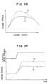
- Fig. 12shows a map for selecting the cam in connection with the degree of opening of an accelerator and the engine speed.
- the cam switchingcan be effected in a three-stage manner.
- a cam A for a small liftis selected.
- the camis sequentially switched to those providing a larger lift.
- Fig. 13shows a map for selecting the cam in connection with the engine torque and the engine speed.
- the cam switchingcan be effected in a three-stage manner.
- the engine torquehas target torque values predetermined with respect to the accelerator opening degree.
- a cam A for a small liftis selected.
- the camis sequentially switched to those providing a larger lift.
- Fig. 14shows a method of controlling the amount of the intake air when switching the air/fuel ratio A/F.
- the fuel amountincreases with the decrease of the air/fuel ratio, so that the engine torque (output torque) increases.
- the air/fuel ratio of around 16the amount of discharge of NOx tends to increase, and therefore the air/fuel ratio is skipped from 18 to 15.
- the air/fuel ratiois switched to 15, with the air amount kept intact, the amount of the fuel increases, so that the engine torque increases as at C. This gives a sense of difference or a feeling of physical disorder.
- the air amountis reduced to prevent the increase of the fuel amount, and the engine torque is changed from A to B (Fig. 14), thereby reducing a shock.
- the air amountis adjusted by the throttle valve or by switching the cam. If this is effected by the throttle valve, the pressure within the intake manifold is decreased, thereby increasing the pumping loss. Therefore, preferably, this is done by switching the cam as much as possible. Also, when the engine torque decreases to such a level that the target engine torque is not achieved even if the air/fuel ratio is not less than 70, the air amount is adjusted by the cam or the throttle valve.
- Fig. 15shows the relation between the amount of the fuel and the engine torque (output torque).
- the engine torquecan be increased by increasing the fuel amount, and therefore the engine torque can be controlled by the fuel amount.
- the amount Qf of injection of fuelis determined by an engine condition detection portion 301 (which detects the conditions of an engine such as an accelerator opening degree ⁇ and an engine speed N) and a fuel injection amount calculation portion 302 which calculates the amount Qf of injection of the fuel.
- the amount of the air of the engineis calculated at a portion 304, and the air amount by each cam is determined, thus calculating the air/fuel ratio. It is judged at a portion 305 whether or not the air/fuel ratio is within a combustible range.
- the camis selected at a portion 306, and the degree of opening of a throttle valve is determined at a portion 307.
- the camis switched to one providing a smaller lift.
- the limit of the lean mixturecan be expanded as compared with a conventional intake port injection system, and therefore the range of the engine torque which can be controlled by the fuel amount is wider. Therefore, the engine torque can be controlled by the fuel amount without the need for finely controlling the air amount as in the conventional system.
- an accelerator opening degreeis detected by a detection means 311, and a target torque is determined by a calculation means 312.
- An amount of fuelis determined by a fuel amount calculation means 313 in accordance with the target torque. If the air/fuel ratio is predetermined with respect to the engine torque (output torque) T at a portion 314, the air amount Qa can be derived. The air/fuel ratio is judged by a judgment means 316. If the air/fuel ratio is not less than 18, a throttle valve is fully opened, i.e. its opening degree ⁇ th ⁇ ⁇ max, at a portion 318, and the torque of the engine is detected by a torque detection means 319, and the fuel injection amount is controlled so that the target torque can be obtained.
- the air amountis controlled by the throttle valve 321 so that the target air/fuel ratio can be achieved.
- the air amountis controlled, for example, by the throttle valve opening degree ⁇ th or the lift by a cam.
- the air amountmay be detected by an air amount sensor 322 to control the air amount to a target value thereof.
- Fig. 18shows a map of the target air/fuel ratio.
- the air/fuel ratiois decreased with the increase of the engine torque (output torque) T.
- the air/fuel ratiois switched to a point C in a manner to skip over the air/fuel ratio value 16.
- the air/fuel ratiois reduced toward a point D. If the air/fuel ratio is further reduced, the mixture becomes too rich. Therefore, preferably, at this region, the air amount is detected, and the air/fuel ratio is controlled.
- Fig. 19shows the relation of the throttle valve opening degree ⁇ th with the engine speed N and the intake air amount Qa.
- the throttle valve opening degreeis found from a map for the intake air amount.
- the air amountis detected, and a feedback is effected.
- Figs. 20 and 21each show control arrangements if the air/fuel ratio is not less than 18 and, the mixture is so lean that the drivability and exhaust cleaning effect may be lowered. Therefore, a combustion variation is detected, and a throttle valve opening degree or a cam lift are so set as to reduce the air amount.
- an electrode or terminal 234is embedded in a cylinder gasket 231 of an engine, and a high voltage is applied thereto from an electrode or terminal 232. Screw holes 233 are formed in the gasket.
- Fig. 23is a vertical cross-sectional view of the portion of Fig. 22.
- a high voltageis applied across electrodes 238 and 239 from an ignition coil, thereby producing a spark discharge.
- the mixtureis ignited at a point near a cylinder wall surface and at other points as well, so that the combustion speed increases.
- a so-called quench region near the wall surfaceis reduced, so that an amount of unburned hydrocarbon is reduced, and also a knocking is less liable to occur.
- Insulating layers 235 and 237are provided on upper and lower surfaces of the gasket, respectively. If the electrode 239 is an earth or ground electrode, the insulating layer 237 may be omitted.
- the amount of the intake airis measured by an air flow meter 501 mounted on an intake manifold.
- An engine speedis detected by a crank angle sensor 509.
- the amount of fuelis determined, and the fuel is injected into the cylinder by a fuel injection valve 502.
- the air amountis controlled by a throttle valve 551, connected to an accelerator wire, and a throttle valve 550 controlled by a motor.
- the air amountmay be controlled only by the throttle valve 550; however, if the throttle valve 551 connected to the accelerator wire is provided, the air amount will not become excessive even in the event of an abnormal operation of the throttle valve 550.
- the air/fuel ratiois detected by an air/fuel ratio sensor connected to the exhaust pipe, and it is examined whether or not a target air/fuel ratio is achieved. If the air/fuel ratio is more lean that the target value, the fuel amount is increased.
- HCis required for reducing NOx in an oxidizing atmosphere, and the temperature of the catalyzer is so controlled that a maximum cleaning efficiency of the catalyzer can be achieved.
- the temperature of the catalyzeris detected by a temperature sensor 528, and the fuel injection amount and the ignition timing are so controlled that the target catalyzer temperature and HC can be obtained.
- a charging operation of a charger 514can be controlled from the outside by a control device 508. The charging operation is effected during a deceleration, thereby recovering a deceleration energy.
- the amount of the intake air into the enginecan be increased by a supercharger 511.
- the operation of the catalyzeris also influenced by the oxygen concentration in the exhaust gas, and therefore an air introduction passageway 534 is provided at an inlet of the catalyzer, and the air amount is controlled by a control valve 534.
- the airmay be supplied by an air pump 535. When the air amount is increased, the catalyzer is cooled by the air, and therefore the air may be used for controlling the temperature of the catalyzer.
- Fig. 25shows the relation between a required torque Tv and the engine torque Te.
- a transmissiongearbox
- the fuel amountis changed.
- a 5th speed5th gear
- the required torque Tvbecomes larger
- the fuel amountis increased to increase the engine torque Te.
- the fuel amountis within a lean combustion limit, and the air/fuel ratio is varied in the range of 30 to 20 so that the amount of NOx can be kept small.
- the range of the air/fuel ratiomay be changed.
- the air/fuel ratiomay be more than 30.
- a pumping lossis reduced when the operation is effected with a large air/fuel ratio, and the fuel consumption is enhanced.
- the gear ratiois increased into a 4th speed.
- the drive torquebecomes excessive, so that a step develops in the torque, thereby adversely affecting the drivability. Therefore, the fuel amount is reduced to decrease the torque to be produced, thereby preventing a stepwise change in the drive torque.
- the gearis sequentially changed.
- the larger the gear ratio becomesthe larger the drive torque becomes. If the air/fuel ratio range of between 20 and 30 is fixedly selected, the gear ratio is selected so that a torque step will not develop. Assuming that the air/fuel ratio is 20 at a 1st speed, when a larger torque than that is required, the air/fuel ratio is further decreased.
- the required torque Tvis determined, for example, by the degree of opening of an accelerator. When the accelerator opening degree is large, the required torque Tv is large.
- Fig. 26shows the relation between the degree ⁇ of opening of the throttle valve and the required torque Tv.
- the throttle valve opening degree ⁇is decreased to reduce the engine torque.
- the throttle valve opening degree ⁇is fully increased, and the gear ratio is sequentially changed.
- the throttle valve openingis controlled in a closing direction so as to minimize a torque step.
- the throttle valve opening degreeis controlled by a motor or the like. Since the control of the throttle valve can be made only in the closing direction of the valve, the engine torque will not increase against the driver's will. It is preferred that the throttle valve be fully opened, but if the operation can be effected in the fully-opened condition because of the performance of the engine, the operation is effected, with the throttle valve opened as much as possible.
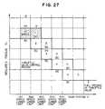
- Fig. 27shows the relation between the required torque Tv and the gear position V for the vehicle speed.
- the gear position Vis changed in accordance with the vehicle speed.
- the gear position Vis increased with the increase of the vehicle speed.
- the gear position Vis decreased, the drive torque can be increased.
- the descriptionwill be given with respect to an example in which the vehicle speed is increased from a low speed, with the throttle valve fully opened.
- the air/fuel ratiois changed from 30 to 20, thereby minimizing or avoiding a torque step.
- the required torquedecreases, the air/fuel ratio is changed from 20 to 30.
- the gearis changed to the 3rd speed, and at this time the air/fuel ratio is changed to 20, thereby avoiding a torque step.
- a similar operationis repeated until the 5th speed.
- the air/fuel ratiois brought into 30 in the fully-opened condition of the throttle valve.
- the fuel amountis increased to change the air/fuel ratio to 20.
- the throttle valve opening degreeis reduced to decrease the air amount.
- the air/fuel ratiois constant, the fuel amount decreases with the decrease of the air amount, so that the torque is reduced.
- the required torqueis small, but is larger than that of the lower limit vehicle speed of the 5th speed, the 5th speed is selected.
- the engine speedbecomes too low.
- the 4th speedis selected if the vehicle speed is higher than the lower limit of the 4th speed.
- the air/fuel ratiois changed to 30, thereby avoiding a torque step.
- the gearis changed to the 3rd speed. The torque is controlled by sequentially changing the gear to the 1st speed in a similar manner.
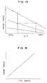
- Fig. 28shows the relation between the vehicle speed lower than the lower limit vehicle speed of the 1st speed and the engine torque Te at an outlet of a torque converter.
- the transmissiongearbox
- the engine speedbecomes too low, and in an extreme case, the engine is stopped.
- a so-called lock-upby which the transmission and the engine are directly connected together
- the transmissionis connected to the engine through the torque converter.
- the vehicle speeddecreases, there develops a slip region where there is a difference in rotational speed between the inlet and outlet of the torque converter. In the slip region, the torque is increased, and the engine torque at the outlet of the torque converter is increased.
- the engine torquecan be changed by the air/fuel ratio.
- the lock-upis released.
- the torque converterinvolves a slip, the torque converter produces a loss of transmission of the energy, so that the fuel consumption is worsened.
- Fig. 29shows a flow chart of the control of the transmission and the engine.
- the gear positionis shifted down by one speed (one gear) so that the engine speed will not be below 800 rpm.
- the gear positionmay be determined in accordance with the minimum allowable engine speed and the vehicle speed. If the gear position is larger than the 1st speed (1st gear), the lock-up is effected.
- the gear positionWhen the gear position is the 1st speed, the gear position can not be shifted down any further even if the engine speed is lower than the minimum allowable engine speed, and therefore the lock-up is released.
- the required engine torque (required torque) for the drive torque required by the driveris calculated.
- the fuel amountis calculated from the required torque, and the air/fuel ratio when fully opening the throttle valve is calculated. If the air/fuel ratio is not less than 30, the combustion becomes unstable, and therefore the throttle valve opening degree is so determined by calculation that the air/fuel ratio becomes 30.
- the associated actuators(the fuel injection valve, the throttle valve and the transmission) are so controlled that the fuel amount, throttle valve opening degree and gear position thus determined can be obtained.
- the gear positionis determined as (r - 1), and the engine speed is calculated again. At this time, the fuel amount is controlled not to produce a drive torque step. Also, when the gear position is the 1st speed (1st gear), the gear position can not be shifted down any further, and therefore the air/fuel ratio is changed from 12 to 15. Since the air/fuel ratio is skipped at this time so as to reduce the amount of discharge of NOx, the throttle valve opening degree is so determined by calculation that a drive torque step will not develop, and the actuators are controlled.
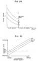
- Fig. 30shows the relation between the accelerator opening degree and the required drive torque. As the accelerator opening degree decreases, the required drive torque is decreased. At the same accelerator opening degree, the required drive torque is decreased as the vehicle speed increases. That the required torque can have a negative value means an engine brake. At the same accelerator opening degree, the higher the vehicle speed is, the more effectively the engine brake acts.
- the required drive torqueis determined for the accelerator opening degree and the vehicle speed, as shown in Fig. 31. These values are stored as a map in a memory of a computer for control purposes. For example, the accelerator opening degree, as well as the vehicle speed, is divided into 16, and 256 values of the required drive torque are stored.
- Fig. 32shows the relation between the engine speed and the engine torque. At the same engine speed, the larger the throttle valve opening degree is, the larger the torque is. By controlling the throttle valve opening degree, the engine torque can be controlled. Also, since the engine torque varies depending on the air/fuel ratio, the torque is controlled by changing the throttle valve opening degree and the fuel amount.
- the amount of the intake airis larger when using supercharging than when not using the supercharging, and the engine torque increases as shown in Fig. 33.
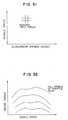
- an exhaust turbo chargeris used as the supercharging means, regardless of the driver's will, the torque characteristics with the supercharging are represented by a curve (a) while the torque characteristics without the supercharging are represented by a curve (b). Therefore, the engine output or power is abruptly increased when effecting the acceleration, and this gives a sense of difference or a feeling of physical disorder.
- Fig. 34is a time chart showing the change of the engine torque and the throttle valve opening degree with time.
- an accelerator pedalWhen an accelerator pedal is pressed down, the amount of the air is increased, so that the fuel injection amount is increased.
- the air amountis abruptly increased, the torque is increased as shown by (b) of Fig. 34 regardless of the driver's will, and this gives the sense of difference.
- the time-dependent change of the engine torque with respect to a time-dependent change of the throttle valve opening degreeis represented by (a) in Fig. 34.
- a certain period of timeis required because of the inertia force before the speed by the supercharging becomes high, and therefore the supercharging becomes effective halfway during the acceleration.
- Fig, 35shows a control block diagram in which the acceleration of the vehicle body is detected by an acceleration sensor, and if a desired drive torque is not obtained, the gear ratio (transmission ratio) of the engine is changed.
- Fig. 36shows the change of the fuel amount and the vehicle body acceleration with time.
- the fuel amountis increased to increase the engine torque.
- the fuelcan be injected directly into the cylinder, and therefore the fuel will not deposit on an intake manifold and the like, and the torque can be controlled with a good response.
- the accelerationis detected, and the fuel amount is so controlled that the target acceleration can be achieved.
- Fig. 37shows the change of the intake air amount, the fuel amount and the vehicle body acceleration with time.
- the fuel amount and the intake air amountare increased to increase the engine torque.
- the intake air amountis controlled by the throttle valve opening degree, but a delay occurs due to a volume of an intake manifold, so that the torque can not be controlled in a good response. Therefore, a large change of the engine torque is controlled by the air amount, and the control for small variations is effected by the fuel amount. In such a control, the range of change of the air/fuel ratio can be narrowed, and also the engine torque can be controlled over a wide range.
- the engine brakeis less liable to act effectively at the time of the deceleration. Therefore, at the time of the deceleration, the electric charger is operated, thereby effecting an electric charging control. By doing so, the engine brake is achieved at the time of the deceleration, and also the energy at the time of the deceleration can be recovered.
- the decelerated conditionfor example, when an injection pulse Tp is not greater than a predetermined value Tpc, the throttle valve opening degree is not greater than a predetermined value, and the engine speed Ne is not less than a predetermined value, it is judged that the deceleration occurs, and the electric charging operation is effected.
- the charging operationis effected regardless of whether or not the injection pulse is below the predetermined value.
- the charging target voltageis increased to increase a charging load.
- Other loadsuch as a fuel heater may be used as the charging load.
- the throttle valveis closed during the deceleration.
- the combustion timeis shortened, the knocking is prevented, the compression ratio of the engine is increased, the heat efficiency is enhanced, and the fuel consumption is enhanced.
- the production of unburned hydrocarboncan be prevented by the stratified intake.
- the response to the fuelis enhanced by the fuel injection within the cylinder. Without increasing the pumping loss, the engine output or power can be controlled in a good response, thereby enhancing the drivability.
Landscapes
- Engineering & Computer Science (AREA)
- Mechanical Engineering (AREA)
- General Engineering & Computer Science (AREA)
- Chemical & Material Sciences (AREA)
- Combustion & Propulsion (AREA)
- Electrical Control Of Air Or Fuel Supplied To Internal-Combustion Engine (AREA)
- Combined Controls Of Internal Combustion Engines (AREA)
- Combustion Methods Of Internal-Combustion Engines (AREA)
- Output Control And Ontrol Of Special Type Engine (AREA)
- Electrical Control Of Ignition Timing (AREA)
Abstract
Description
Claims (14)
- A spark-ignition internal combustion engine comprising:a combustion chamber;a fuel injection means (13) for injecting fuel;an air amount control means (28) for controlling intake air amount into acombustion chamber (7);an ignition means (14) for igniting the mixture of air and fuel in saidcombustion chamber (7); andan engine controlling means (5) coupled to said fuel injection means (13), saidair amount control means (28) and said ignition means (14), respectively,wherein said engine controlling means (5) has a first control mode in which anengine torque is changed when an air/fuel ratio is varied and a second controlmode in which the engine torque is changed by controlling a throttle valve (22)while maintaining a substantially fixed air/fuel ratio, the engine torque in thesecond control mode is smaller than a predetermined value and the enginetorque in the first mode is larger than said predetermined value.
- A spark-ignition internal combustion engine according to claim 1, wherein saidengine controlling means (5) has said first control mode in which an enginetorque is changed when said air/fuel ratio is varied and a third control mode inwhich the engine torque is changed while maintaining a substantially fixedair/fuel ratio, and the engine torque in the first control mode is smaller than thatin the third control mode.
- A spark-ignition internal combustion engine according to claim 1 or 2, whereinan injection port of said fuel injection means (13) is disposed at the inside ofsaid combustion chamber (7).
- A spark-ignition internal combustion engine according to at least one of claims1 to 3, wherein an engine torque is controlled by varying said air/fuel ratio insaid first control mode.
- A spark-ignition internal combustion engine according to at least one of claims1 to 4, wherein an engine torque is controlled by varying an air/fuel ratio withina range greater than a stoichiometric ratio to control engine torque in a firstcontrol mode.
- A spark-ignition internal combustion engine according to at least one of claims1 to 5, wherein the first and second control modes are selected to keep theamount of NOx provided by combustion small.
- A spark-ignition internal combustion engine according to claim 6, wherein saidengine controller operates so that an air/fuel ratio of 18 to 15 is skipped.
- A method of controlling an internal combustion engine, comprising:
controlling an air/fuel ratio by controlling at least one of an amount of fuelinjected from a fuel injection means (13) and an amount of air controlled by athrottle valve (22) such that when an engine torque is smaller than apredetermined value, said throttle valve (22) is controlled while keeping theair/fuel ratio generally constant, and when the engine torque is larger than saidpredetermined value, the air/fuel ratio is controlled to vary. - Method of controlling an internal combustion engine, wherein said enginecontrolling means (5) has said first control mode in which an engine torque ischanged when said air/fuel ratio is varied and a third control mode in which theengine torque is changed while maintaining a substantially fixed air/fuel ratio,and the engine torque in the first control mode is smaller than that in the thirdcontrol mode.
- A method of controlling an internal combustion engine according to claim 8 or9, wherein said fuel injection means (13) injects fuel directly into a combustionchamber (7).
- A method of controlling an internal combustion engine according to at least oneof claims 8 to 10, wherein when said engine torque is large, the air/fuel ratio iscontrolled to vary within range to control engine torque.
- A method of controlling an internal combustion engine according to at least oneof claims 8 to 11, wherein when said engine torque is large, the air/fuel ratio iscontrolled to vary within range greater than a stoichiometric ratio to controlengine torque.
- A method of controlling an internal combustion engine according to at least oneof claims 8 to 12, wherein the air/fuel ratio is controlled to keep the amount ofNOx provided by combustion small.
- A method of controlling an internal combustion engine according to at least oneof claims 8 to 13, wherein the air/fuel ratio is controlled to skip the air/fuel ratiobetween 15 and 18.
Applications Claiming Priority (6)
| Application Number | Priority Date | Filing Date | Title |
|---|---|---|---|
| JP33492893 | 1993-12-28 | ||
| JP33492893AJP3635670B2 (en) | 1993-12-28 | 1993-12-28 | Control apparatus and method for spark ignition internal combustion engine |
| JP33489593 | 1993-12-28 | ||
| JP33489593AJP4075080B2 (en) | 1993-12-28 | 1993-12-28 | Control device for automobile and control method thereof |
| EP98113882AEP0890725B1 (en) | 1993-12-28 | 1994-12-22 | Apparatus for and method of controlling internal combustion engine |
| EP94309682AEP0661432B1 (en) | 1993-12-28 | 1994-12-22 | Apparatus for and method of controlling internal combustion engine |
Related Parent Applications (1)
| Application Number | Title | Priority Date | Filing Date |
|---|---|---|---|
| EP98113882ADivisionEP0890725B1 (en) | 1993-12-28 | 1994-12-22 | Apparatus for and method of controlling internal combustion engine |
Publications (3)
| Publication Number | Publication Date |
|---|---|
| EP1136685A2true EP1136685A2 (en) | 2001-09-26 |
| EP1136685A3 EP1136685A3 (en) | 2002-04-03 |
| EP1136685B1 EP1136685B1 (en) | 2004-06-16 |
Family
ID=26574981
Family Applications (3)
| Application Number | Title | Priority Date | Filing Date |
|---|---|---|---|
| EP01110090AExpired - LifetimeEP1136685B1 (en) | 1993-12-28 | 1994-12-22 | Apparatus for and method of controlling an internal combustion engine |
| EP94309682AExpired - LifetimeEP0661432B1 (en) | 1993-12-28 | 1994-12-22 | Apparatus for and method of controlling internal combustion engine |
| EP98113882AExpired - LifetimeEP0890725B1 (en) | 1993-12-28 | 1994-12-22 | Apparatus for and method of controlling internal combustion engine |
Family Applications After (2)
| Application Number | Title | Priority Date | Filing Date |
|---|---|---|---|
| EP94309682AExpired - LifetimeEP0661432B1 (en) | 1993-12-28 | 1994-12-22 | Apparatus for and method of controlling internal combustion engine |
| EP98113882AExpired - LifetimeEP0890725B1 (en) | 1993-12-28 | 1994-12-22 | Apparatus for and method of controlling internal combustion engine |
Country Status (4)
| Country | Link |
|---|---|
| US (6) | US5666916A (en) |
| EP (3) | EP1136685B1 (en) |
| KR (1) | KR100377645B1 (en) |
| DE (3) | DE69433853T2 (en) |
Cited By (7)
| Publication number | Priority date | Publication date | Assignee | Title |
|---|---|---|---|---|
| FR2830570A1 (en)* | 2001-10-10 | 2003-04-11 | Peugeot Citroen Automobiles Sa | I.c. engine with controlled ignition has direct fuel injection system operating at very high pressure |
| GB2355492B (en)* | 1999-10-18 | 2004-02-18 | Ford Global Tech Inc | Engine control during changes in cylinder AFR |
| US6705284B2 (en) | 1999-10-18 | 2004-03-16 | Ford Global Technologies, Llc | Engine method |
| US6945225B2 (en) | 1999-10-18 | 2005-09-20 | Ford Global Technologies, Llc | Speed control method |
| US7367316B2 (en) | 1999-10-18 | 2008-05-06 | Ford Global Technologies, Llc | Vehicle control system |
| US7398762B2 (en) | 2001-12-18 | 2008-07-15 | Ford Global Technologies, Llc | Vehicle control system |
| CN112343331A (en)* | 2020-10-10 | 2021-02-09 | 上海建工七建集团有限公司 | Method for erecting special-shaped curved surface bare concrete formwork |
Families Citing this family (131)
| Publication number | Priority date | Publication date | Assignee | Title |
|---|---|---|---|---|
| EP0588627B1 (en)* | 1992-09-16 | 1997-11-12 | Hitachi, Ltd. | Driving force control system for a vehicle |
| US5549087A (en)* | 1995-04-27 | 1996-08-27 | The United States Of America As Represented By The Administrator Of The U.S. Environmental Protection Agency | Combined cycle engine |
| JPH08312438A (en)* | 1995-05-12 | 1996-11-26 | Yamaha Motor Co Ltd | Fuel injection method and fuel injection control device in two-cycle engine |
| JP3152106B2 (en)* | 1995-05-16 | 2001-04-03 | 三菱自動車工業株式会社 | Control device for in-cylinder injection spark ignition internal combustion engine |
| JPH0960543A (en)* | 1995-08-24 | 1997-03-04 | Hitachi Ltd | Engine controller |
| JP3201936B2 (en)* | 1995-09-29 | 2001-08-27 | 株式会社日立製作所 | Control device for in-cylinder injection engine |
| DE19537465B4 (en)* | 1995-10-07 | 2007-07-12 | Robert Bosch Gmbh | Method and device for controlling an internal combustion engine |
| US5609131A (en)* | 1995-10-11 | 1997-03-11 | The United States Of America As Represented By The Administrator Of The U.S. Environmental Protection Agency | Multi-stage combustion engine |
| DE19602065C2 (en)* | 1996-01-20 | 2001-08-09 | Daimler Chrysler Ag | Method for operating an internal combustion engine |
| DE19612150A1 (en)* | 1996-03-27 | 1997-10-02 | Bosch Gmbh Robert | Control device for fuel-injected engine |
| DE19631986A1 (en)* | 1996-08-08 | 1998-02-12 | Bosch Gmbh Robert | Control unit for vehicle direct injection IC petrol engine |
| JP3209112B2 (en)* | 1996-09-17 | 2001-09-17 | トヨタ自動車株式会社 | Idle speed control device for stratified combustion engine |
| JP3763491B2 (en)* | 1996-10-08 | 2006-04-05 | 富士重工業株式会社 | Combustion chamber structure of in-cylinder injection engine |
| DE19645383B4 (en)* | 1996-11-04 | 2004-04-29 | Daimlerchrysler Ag | Method for operating an Otto internal combustion engine with internal mixture formation |
| JP3257423B2 (en)* | 1996-12-12 | 2002-02-18 | 三菱自動車工業株式会社 | Exhaust heating device |
| JP3248439B2 (en)* | 1996-12-13 | 2002-01-21 | 三菱自動車工業株式会社 | Control device for in-cylinder injection type internal combustion engine |
| JP3250475B2 (en)* | 1996-12-13 | 2002-01-28 | 三菱自動車工業株式会社 | Control device for in-cylinder injection type internal combustion engine |
| JP3189734B2 (en)* | 1996-12-19 | 2001-07-16 | 三菱自動車工業株式会社 | Spark ignition direct injection internal combustion engine |
| JPH10184417A (en)* | 1996-12-25 | 1998-07-14 | Hitachi Ltd | Control device for in-cylinder injection internal combustion engine |
| FR2758590B1 (en)* | 1997-01-20 | 1999-04-16 | Siemens Automotive Sa | CONTROL DEVICE FOR AN INTERNAL COMBUSTION ENGINE WITH DIRECT IGNITION AND DIRECT INJECTION |
| JP3554167B2 (en)* | 1997-12-02 | 2004-08-18 | 株式会社日立製作所 | Control device for in-cylinder injection engine |
| DE19712357B4 (en)* | 1997-03-25 | 2004-05-06 | Harald Echtle | Method for mixture formation in a direct injection internal combustion engine |
| FR2763647B1 (en)* | 1997-05-23 | 1999-07-02 | Renault | INTERNAL COMBUSTION ENGINE WITH CONTROLLED IGNITION |
| JP3355997B2 (en) | 1997-05-30 | 2002-12-09 | 株式会社日立製作所 | Internal combustion engine control method |
| EP0887533B1 (en)* | 1997-06-25 | 2004-08-18 | Nissan Motor Company, Limited | Direct-injection spark-ignition type engine control apparatus |
| FR2765629B1 (en)* | 1997-07-01 | 2002-02-01 | Renault | DIRECT INJECTION ENGINE AND CONTROLLED IGNITION |
| JPH1136929A (en)* | 1997-07-23 | 1999-02-09 | Mazda Motor Corp | Intake control device for engine |
| JP3693211B2 (en)* | 1997-09-01 | 2005-09-07 | スズキ株式会社 | In-cylinder injection engine |
| EP0911506A3 (en)* | 1997-10-21 | 2000-12-27 | Hitachi, Ltd. | Electronically controlled throttle apparatus for an engine |
| DE19747231A1 (en)* | 1997-10-25 | 1999-04-29 | Bosch Gmbh Robert | Method for injecting fuel into the combustion chambers of an air-compressing, self-igniting internal combustion engine |
| JP3368217B2 (en)* | 1997-11-26 | 2003-01-20 | マツダ株式会社 | Engine control device |
| JP3518366B2 (en)* | 1997-11-26 | 2004-04-12 | マツダ株式会社 | Engine control device |
| JP3945040B2 (en)* | 1997-11-26 | 2007-07-18 | マツダ株式会社 | Engine control device |
| JP3506018B2 (en)* | 1997-11-26 | 2004-03-15 | マツダ株式会社 | Engine control device |
| JP3815100B2 (en)* | 1998-02-20 | 2006-08-30 | マツダ株式会社 | Engine control device |
| DE19810466C2 (en)* | 1998-03-11 | 1999-12-30 | Daimler Chrysler Ag | Process for operating a gasoline engine with direct injection |
| US20020121266A1 (en)* | 2000-08-31 | 2002-09-05 | Hitachi, Ltd. | Internal combustion engine, and control apparatus and method thereof |
| SE519908C2 (en)* | 1998-03-20 | 2003-04-22 | Volvo Car Corp | Method and apparatus for controlling combustion engine |
| DE19857785C2 (en) | 1998-12-15 | 2000-12-07 | Daimler Chrysler Ag | Method for mixture formation in a combustion chamber of an internal combustion engine |
| JP2000054928A (en)* | 1998-08-07 | 2000-02-22 | Kokusan Denki Co Ltd | 2-cycle internal combustion engine |
| US6257197B1 (en) | 1998-09-29 | 2001-07-10 | Mazda Motor Corporation | Control system for a direct injection-spark ignition engine |
| US6513320B1 (en) | 1998-09-29 | 2003-02-04 | Mazda Motor Corporation | Control system for a direct injection-spark ignition engine |
| DE19852600A1 (en)* | 1998-11-14 | 2000-05-18 | Bosch Gmbh Robert | Method for operating an internal combustion engine, in particular a motor vehicle |
| JP3985375B2 (en)* | 1999-01-14 | 2007-10-03 | 日産自動車株式会社 | Engine intake control device |
| US6314939B1 (en)* | 1999-03-11 | 2001-11-13 | Outboard Marine Corporation | Methods and apparatus for controlling engine operation |
| US6434466B1 (en)* | 1999-05-06 | 2002-08-13 | Ford Global Technologies, Inc. | System and method for determining engine torque for controlling a powertrain |
| US6125823A (en)* | 1999-05-27 | 2000-10-03 | Detroit Diesel Corporation | System and method for controlling fuel injections |
| US6188944B1 (en)* | 1999-06-01 | 2001-02-13 | Ford Motor Company | Torque control strategy for engines with continuously variable transmission |
| JP2000356143A (en)* | 1999-06-14 | 2000-12-26 | Toyota Motor Corp | Combustion control device for internal combustion engine |
| US6978764B1 (en) | 1999-10-18 | 2005-12-27 | Ford Global Technologies, Inc. | Control method for a vehicle having an engine |
| US6219611B1 (en) | 1999-10-18 | 2001-04-17 | Ford Global Technologies, Inc. | Control method for engine having multiple control devices |
| US6250283B1 (en) | 1999-10-18 | 2001-06-26 | Ford Global Technologies, Inc. | Vehicle control method |
| JP3731403B2 (en)* | 1999-09-09 | 2006-01-05 | 日産自動車株式会社 | Control device for direct-injection spark-ignition internal combustion engine |
| US6182636B1 (en) | 1999-10-18 | 2001-02-06 | Ford Global Technologies, Inc. | Lean burn engine speed control |
| US6244242B1 (en) | 1999-10-18 | 2001-06-12 | Ford Global Technologies, Inc. | Direct injection engine system and method |
| US6209526B1 (en) | 1999-10-18 | 2001-04-03 | Ford Global Technologies, Inc. | Direct injection engine system |
| US6324835B1 (en) | 1999-10-18 | 2001-12-04 | Ford Global Technologies, Inc. | Engine air and fuel control |
| DE19960166A1 (en) | 1999-12-14 | 2001-06-21 | Fev Motorentech Gmbh | Method for regulating the boost pressure on a piston internal combustion engine with a turbocharger |
| JP2001193524A (en)* | 1999-12-28 | 2001-07-17 | Mitsubishi Electric Corp | Fuel injection control device for in-cylinder injection engine |
| FR2804179B1 (en)* | 2000-01-20 | 2002-12-06 | Peugeot Citroen Automobiles Sa | METHOD AND DEVICE FOR REGULATING THE RICHNESS OF THE MIXTURE OF AN INTERNAL COMBUSTION ENGINE |
| US6352490B1 (en) | 2000-02-04 | 2002-03-05 | Ford Global Technologies, Inc. | Optimization method for a lean capable multi-mode engine |
| JP2001248484A (en)* | 2000-02-29 | 2001-09-14 | Hitachi Ltd | In-cylinder injection engine, control device thereof, and control method |
| US6513484B1 (en)* | 2000-03-03 | 2003-02-04 | Ford Global Technologies, Inc. | Boosted direct injection stratified charge gasoline engines |
| US6278933B1 (en)* | 2000-04-28 | 2001-08-21 | Ford Global Technologies, Inc. | Rapid transient torque management in DISI engines |
| US6378484B1 (en)* | 2000-05-15 | 2002-04-30 | Ford Global Technologies, Inc. | Coordinated control of valve timing during mode transitions of direct injection stratified charge engines |
| JP3804402B2 (en)* | 2000-05-19 | 2006-08-02 | トヨタ自動車株式会社 | Vehicle driving force control device and driving force control method |
| US6405706B1 (en)* | 2000-08-02 | 2002-06-18 | Ford Global Tech., Inc. | System and method for mixture preparation control of an internal combustion engine |
| JP2002183593A (en)* | 2000-09-20 | 2002-06-28 | Masami Isomura | Signboard information retrieval system |
| JP3616320B2 (en)* | 2000-09-21 | 2005-02-02 | 本田技研工業株式会社 | Ignition timing control device for internal combustion engine |
| JP2002130072A (en)* | 2000-10-18 | 2002-05-09 | Toyota Motor Corp | Fuel injection device for internal combustion engine |
| JP3870692B2 (en)* | 2000-11-24 | 2007-01-24 | トヨタ自動車株式会社 | In-cylinder injection spark ignition internal combustion engine |
| US6360713B1 (en)* | 2000-12-05 | 2002-03-26 | Ford Global Technologies, Inc. | Mode transition control scheme for internal combustion engines using unequal fueling |
| EP1217186B1 (en) | 2000-12-20 | 2015-07-29 | Institut Français du Pétrole | Direct injection engine with small spray angle and methods of using such an engine |
| FR2818324B1 (en)* | 2000-12-20 | 2003-05-16 | Inst Francais Du Petrole | DIRECT INJECTION ENGINE WITH A LOW ANGLE INJECTOR |
| FR2818325B1 (en)* | 2001-07-30 | 2006-02-03 | Inst Francais Du Petrole | DIRECT INJECTION ENGINE PROVIDED WITH A LOW CORE ANGLE AND METHODS FOR USING SUCH ENGINE |
| JP3852303B2 (en)* | 2001-02-05 | 2006-11-29 | トヨタ自動車株式会社 | Control device for multi-cylinder internal combustion engine |
| FR2820461B1 (en)* | 2001-02-05 | 2003-05-02 | Siemens Automotive Sa | METHOD AND DEVICE FOR ADJUSTING THE OPENING TIMING OF A FUEL INJECTOR FOR A DIRECT INJECTION INTERNAL COMBUSTION ENGINE |
| JP4477249B2 (en)* | 2001-02-07 | 2010-06-09 | 本田技研工業株式会社 | In-cylinder injection internal combustion engine control device |
| DE10106169A1 (en)* | 2001-02-10 | 2002-08-14 | Bosch Gmbh Robert | Method and device for controlling an operation of an internal combustion engine |
| JP2002276421A (en)* | 2001-03-19 | 2002-09-25 | Mazda Motor Corp | Control device for in-cylinder injection engine |
| DE10115401A1 (en)* | 2001-03-29 | 2002-10-02 | Daimler Chrysler Ag | Fuel injection system for an internal combustion engine |
| KR100397977B1 (en)* | 2001-05-23 | 2003-09-19 | 현대자동차주식회사 | Engine control method for eliminating emission during cold start and idle for a vehicle |
| WO2003010428A1 (en)* | 2001-07-02 | 2003-02-06 | Hitachi, Ltd. | Cylinder direct injection type internal combustion engine |
| AT5720U1 (en)* | 2001-09-25 | 2002-10-25 | Avl List Gmbh | Internal combustion engine |
| DE10147171B4 (en)* | 2001-09-25 | 2007-11-29 | Siemens Ag | Method for direct injection of fuel in the form of two injections with different injection angles and a control device for injection |
| DE10149236A1 (en)* | 2001-10-05 | 2003-04-30 | Bosch Gmbh Robert | Method for operating an internal combustion engine, in particular a motor vehicle |
| JP3789804B2 (en)* | 2001-10-30 | 2006-06-28 | 本田技研工業株式会社 | Ignition control device for turbocharged engine |
| JP3879568B2 (en)* | 2002-04-08 | 2007-02-14 | トヨタ自動車株式会社 | In-cylinder injection spark ignition internal combustion engine |
| DE10234849A1 (en)* | 2002-07-31 | 2004-02-19 | Robert Bosch Gmbh | Combustion engine control method, in which its output torque and combustion chamber lambda value are regulated in two different operating modes, with priority given to maintaining a constant set torque |
| DE10244364A1 (en)* | 2002-09-24 | 2004-04-01 | Daimlerchrysler Ag | Internal combustion engine with auto-ignition |
| DE10258249A1 (en)* | 2002-12-13 | 2004-07-15 | Dr.Ing.H.C. F. Porsche Ag | Method for changing the valve timing of an internal combustion engine |
| DE10259052B3 (en)* | 2002-12-17 | 2004-04-01 | Siemens Ag | Heating method for exhaust catalyzer of direct fuel injection IC engine for automobile using increased exothermy in catalyzer for accelerated heating during cold-starting |
| DE10308789A1 (en)* | 2003-02-28 | 2004-09-16 | Man B & W Diesel Ag | Process for optimizing the working and combustion process of a diesel engine |
| DE10321881A1 (en)* | 2003-05-15 | 2004-12-02 | Daimlerchrysler Ag | Method for switching the stroke of intake valves of an internal combustion engine |
| FR2857407B1 (en)* | 2003-07-01 | 2009-05-15 | Volkswagen Ag | METHOD FOR OPERATING A DIRECT INJECTION SPARK IGNITION ENGINE, AND DIRECT INJECTION SPARK IGNITION ENGINE |
| JP3966243B2 (en)* | 2003-07-09 | 2007-08-29 | トヨタ自動車株式会社 | Internal combustion engine |
| EP2325466B1 (en)* | 2003-07-22 | 2012-08-22 | Toyota Jidosha Kabushiki Kaisha | Device for detecting variation between cylinders of and device for detecting variation between banks of internal combustion engine |
| DE10336606B4 (en)* | 2003-08-08 | 2007-01-25 | Siemens Ag | Actuation method and actuator for an actuator |
| US20050044843A1 (en)* | 2003-08-28 | 2005-03-03 | Price Kenneth S. | Method and apparatus for controlling exhaust emissions from a compression-ignition engine |
| DE10354102A1 (en)* | 2003-11-19 | 2005-06-02 | Bayerische Motoren Werke Ag | Process for operating a direct injection internal combustion engine with spark-ignition comprises injecting fuel during the compression phase in the event of a high load |
| DE102004023409B4 (en)* | 2004-05-12 | 2007-05-16 | Gottfried Schubert | High-compression gasoline engine with throttle control, spark ignition and direct fuel injection into a pre-combustion chamber |
| JP4539211B2 (en)* | 2004-07-23 | 2010-09-08 | 日産自動車株式会社 | Control device for internal combustion engine |
| US7152559B2 (en)* | 2004-07-26 | 2006-12-26 | General Motors Corporation | Valve and fueling strategy for operating a controlled auto-ignition four-stroke internal combustion engine |
| US7128047B2 (en)* | 2004-07-26 | 2006-10-31 | General Motors Corporation | Valve and fueling strategy for operating a controlled auto-ignition four-stroke internal combustion engine |
| US7150250B2 (en)* | 2004-07-26 | 2006-12-19 | General Motors Corporation | Valve and fueling strategy for operating a controlled auto-ignition four-stroke internal combustion engine |
| FR2882100B1 (en)* | 2005-02-16 | 2010-08-20 | Inst Francais Du Petrole | FUEL INJECTION CONTROL METHOD FOR INTERNAL COMBUSTION ENGINE AND ENGINE USING SUCH A METHOD |
| FR2882785B1 (en)* | 2005-03-03 | 2007-08-31 | Peugeot Citroen Automobiles Sa | INTERNAL COMBUSTION ENGINE WITH RECYCLING OF PRE-COMBUSTION COMBUSTION AND IGNITION PRODUCTS, METHOD OF OPERATION THEREOF |
| US7578281B2 (en)* | 2006-03-17 | 2009-08-25 | Ford Global Technologies, Llc | First and second spark plugs for improved combustion control |
| US7832370B2 (en)* | 2006-11-16 | 2010-11-16 | Gm Global Technology Operations, Inc. | Low-load operation extension of a homogeneous charge compression ignition engine |
| FR2915241B1 (en)* | 2007-04-19 | 2009-06-05 | Renault Sas | INTERNAL COMBUSTION ENGINE WITH REGULATION OF FUEL INJECTION QUANTITY AND METHOD FOR PRODUCING FUEL INJECTION SET VALUE. |
| US7689344B2 (en)* | 2007-06-08 | 2010-03-30 | Gm Global Technology Operations, Inc. | Method and apparatus for controlling transitions in an engine having multi-step valve lift |
| US7822531B2 (en)* | 2008-04-28 | 2010-10-26 | Southwest Research Institute | Stratified charge gasoline direct injection systems using exhaust gas recirculation |
| US8365528B2 (en)* | 2009-01-06 | 2013-02-05 | Ford Global Technologies, Llc | Engine valve duration control for improved scavenging |
| AT507802B1 (en) | 2009-03-17 | 2010-08-15 | Vaillant Group Austria Gmbh | METHOD FOR PERFORMANCE MODULATION IN MOTOR BLOCK HEATING PLANTS |
| JP2012026340A (en)* | 2010-07-22 | 2012-02-09 | Denso Corp | Fuel injection control device for direct injection internal combustion engine |
| US8272362B2 (en)* | 2011-03-29 | 2012-09-25 | Ford Global Technologies, Llc | Engine control method and system |
| US20120330534A1 (en)* | 2011-06-27 | 2012-12-27 | Cleeves James M | Enhanced efficiency and pollutant control by multi-variable engine operation control |
| DE102011107540B4 (en)* | 2011-07-16 | 2013-05-23 | Audi Ag | A method of operating a motor vehicle in a sports mode of operation |
| US9404468B2 (en)* | 2013-08-16 | 2016-08-02 | Ford Global Technologies, Llc | Method and system for torque control |
| WO2015064527A1 (en)* | 2013-10-28 | 2015-05-07 | ヤンマー株式会社 | Auxiliary-chamber-type gas engine |
| JP6365831B2 (en)* | 2014-07-17 | 2018-08-01 | 三菱自動車工業株式会社 | Fuel injection control device for internal combustion engine |
| US10584639B2 (en) | 2014-08-18 | 2020-03-10 | Woodward, Inc. | Torch igniter |
| TWI547636B (en)* | 2014-10-31 | 2016-09-01 | 光陽工業股份有限公司 | Vechicle fuel consumption detection system and detection method |
| NL1041155B1 (en)* | 2015-01-23 | 2017-01-05 | Johan Willem Maria Nooijen Paul | Dual Fuel injector and methods. |
| DE102015213893A1 (en)* | 2015-07-23 | 2017-01-26 | Robert Bosch Gmbh | Method for determining a transition compensation in an internal combustion engine with intake manifold injection and direct injection |
| DE102015218835B3 (en)* | 2015-09-30 | 2016-11-24 | Continental Automotive Gmbh | Method and apparatus for injecting gaseous fuel |
| JP6881341B2 (en)* | 2018-01-31 | 2021-06-02 | トヨタ自動車株式会社 | Vehicle control device |
| US11421601B2 (en) | 2019-03-28 | 2022-08-23 | Woodward, Inc. | Second stage combustion for igniter |
| JP2021060026A (en)* | 2019-10-09 | 2021-04-15 | トヨタ自動車株式会社 | Vehicle and control method for the same |
| EP4048879A4 (en) | 2019-10-24 | 2023-08-16 | Volvo Truck Corporation | System and method for controlling engine fueling and vehicle including such a system |
| EP4168661A1 (en) | 2020-06-23 | 2023-04-26 | Woodward, Inc. | Ignition system for power generation engine |
Family Cites Families (44)
| Publication number | Priority date | Publication date | Assignee | Title |
|---|---|---|---|---|
| GB528584A (en)* | 1939-04-03 | 1940-11-01 | Hesselman Motor Corp Ltd | Improvements in or relating to internal combustion engines of the liquid fuel injection type |
| DE1916167A1 (en)* | 1969-03-28 | 1970-10-15 | Daimler Benz Ag | Device for controlling an internal combustion engine |
| US3918543A (en)* | 1973-12-26 | 1975-11-11 | Norman Halem | System for employing the change of momentum during vehicle deceleration for accessory power |
| DE2842389C2 (en)* | 1978-09-29 | 1984-04-12 | Robert Bosch Gmbh, 7000 Stuttgart | Device for setting the torque of an internal combustion engine |
| JPS56118536A (en)* | 1980-02-22 | 1981-09-17 | Toyota Motor Corp | Air fuel ratio controller for engine |
| JPH0639923B2 (en)* | 1983-07-28 | 1994-05-25 | マツダ株式会社 | Stratified charge engine |
| JPS60153474A (en)* | 1984-01-20 | 1985-08-12 | Mazda Motor Corp | Exhaust purification device for engine |
| US4708101A (en)* | 1984-12-20 | 1987-11-24 | Nissan Motor Co., Ltd. | Driving apparatus for intake and exhaust valves of internal combustion engine |
| JP2507315B2 (en)* | 1986-03-26 | 1996-06-12 | 株式会社日立製作所 | Internal combustion engine controller |
| US4724723A (en)* | 1986-07-30 | 1988-02-16 | General Motors Corporation | Closed loop shift quality control system |
| JPS63248938A (en)* | 1987-04-06 | 1988-10-17 | Mazda Motor Corp | Stratified combustion controller for engine |
| US5021956A (en)* | 1988-04-25 | 1991-06-04 | Mazda Motor Corporation | Control systems for vehicle engines coupled with automatic transmissions |
| US5123397A (en)* | 1988-07-29 | 1992-06-23 | North American Philips Corporation | Vehicle management computer |
| DE3831539C3 (en) | 1988-09-16 | 2001-06-13 | Kaltenbach & Voigt | Control arrangement for a dental furnace, in particular a microprocessor-controlled preheating furnace |
| US5012695A (en)* | 1988-10-07 | 1991-05-07 | Mazda Motor Corporation | Gear-shifting shock suppressing system for automatic transmission vehicle |
| JPH0635812B2 (en)* | 1988-10-31 | 1994-05-11 | いすゞ自動車株式会社 | Electromagnetically driven valve controller |
| EP0369480A3 (en)* | 1988-11-18 | 1991-01-02 | Toyota Jidosha Kabushiki Kaisha | An internal combustion engine |
| JPH02153257A (en) | 1988-12-02 | 1990-06-12 | Hitachi Ltd | Internal combustion engine fuel supply system |
| JPH02181009A (en)* | 1988-12-28 | 1990-07-13 | Isuzu Motors Ltd | Controller for electromagnetic valve |
| JPH02196152A (en)* | 1989-01-26 | 1990-08-02 | Nissan Motor Co Ltd | Air-fuel ratio controller for internal combustion engine |
| JP2948230B2 (en)* | 1989-02-21 | 1999-09-13 | マツダ株式会社 | Engine control device for vehicle with automatic transmission |
| JPH086568B2 (en)* | 1989-04-13 | 1996-01-24 | 日産自動車株式会社 | Engine valve operation control device |
| JPH03229936A (en)* | 1990-02-02 | 1991-10-11 | Hitachi Ltd | Engine control method and control device |
| EP0451462B1 (en)* | 1990-02-15 | 1994-11-02 | Fujitsu Ten Limited | Lean burn internal combustion engine |
| US5078107A (en)* | 1990-03-30 | 1992-01-07 | Fuji Jukogyo Kabushiki Kaisha | Fuel injection control system for an internal combustion engine |
| KR0182775B1 (en)* | 1990-04-18 | 1999-04-01 | 미다 가쓰시게 | Torque control method and apparatus for internal combustion engine and motor vehicles employing the same |
| GB2248087B (en)* | 1990-09-04 | 1994-05-18 | Ford Motor Co | Engine fuelling system |
| US5046466A (en)* | 1990-09-20 | 1991-09-10 | Lipski Frank F | Spark-ignition engine |
| JPH04183945A (en)* | 1990-11-19 | 1992-06-30 | Toyota Motor Corp | In-cylinder direct injection spark ignition engine |
| JP2687718B2 (en)* | 1990-11-21 | 1997-12-08 | 日産自動車株式会社 | Cam switching control device for internal combustion engine |
| JP2707832B2 (en)* | 1990-11-26 | 1998-02-04 | 日産自動車株式会社 | Output control device for internal combustion engine |
| JP2636498B2 (en)* | 1990-11-29 | 1997-07-30 | 日産自動車株式会社 | Engine control device |
| US5470290A (en)* | 1991-02-25 | 1995-11-28 | Hitachi, Ltd. | Change gear control device using acceleration and gear ratio as parameters for automatic transmission in a motor vehicle and the method therefor |
| US5211147A (en)* | 1991-04-15 | 1993-05-18 | Ward Michael A V | Reverse stratified, ignition controlled, emissions best timing lean burn engine |
| US5255641A (en)* | 1991-06-24 | 1993-10-26 | Ford Motor Company | Variable engine valve control system |
| JP2585898B2 (en)* | 1991-07-29 | 1997-02-26 | 本田技研工業株式会社 | Air-fuel ratio control device for internal combustion engine |
| JP2765305B2 (en)* | 1991-10-25 | 1998-06-11 | トヨタ自動車株式会社 | Internal combustion engine |
| JP2917617B2 (en)* | 1991-10-28 | 1999-07-12 | トヨタ自動車株式会社 | Internal combustion engine |
| US5241855A (en)* | 1991-10-31 | 1993-09-07 | Ford Motor Company | Method and apparatus for inferring engine torque |
| EP0547817B1 (en)* | 1991-12-11 | 1996-10-30 | Toyota Jidosha Kabushiki Kaisha | Control system for both engine and automatic transmission |
| US5201296A (en)* | 1992-03-30 | 1993-04-13 | Caterpillar Inc. | Control system for an internal combustion engine |
| JPH0681719A (en)* | 1992-08-31 | 1994-03-22 | Hitachi Ltd | Intake device of internal combustion engine |
| US5237968A (en) | 1992-11-04 | 1993-08-24 | Caterpillar Inc. | Apparatus for adjustably controlling valve movement and fuel injection |
| US6305347B1 (en)* | 2000-03-06 | 2001-10-23 | Ford Global Technologies, Inc. | Monitor for lean capable engine |
- 1994
- 1994-12-22DEDE69433853Tpatent/DE69433853T2/ennot_activeExpired - Fee Related
- 1994-12-22DEDE69416502Tpatent/DE69416502T2/ennot_activeExpired - Fee Related
- 1994-12-22DEDE69430596Tpatent/DE69430596T2/ennot_activeExpired - Fee Related
- 1994-12-22EPEP01110090Apatent/EP1136685B1/ennot_activeExpired - Lifetime
- 1994-12-22EPEP94309682Apatent/EP0661432B1/ennot_activeExpired - Lifetime
- 1994-12-22EPEP98113882Apatent/EP0890725B1/ennot_activeExpired - Lifetime
- 1994-12-23USUS08/362,878patent/US5666916A/ennot_activeExpired - Fee Related
- 1994-12-23KRKR1019940036167Apatent/KR100377645B1/ennot_activeExpired - Fee Related
- 1997
- 1997-05-01USUS08/850,012patent/US5875761A/ennot_activeExpired - Fee Related
- 1999
- 1999-01-25USUS09/236,321patent/US6148791A/ennot_activeExpired - Fee Related
- 2000
- 2000-11-13USUS09/709,404patent/US6343585B1/ennot_activeExpired - Fee Related
- 2002
- 2002-01-29USUS10/057,922patent/US6453871B1/ennot_activeExpired - Fee Related
- 2002-09-10USUS10/237,706patent/US6644270B2/ennot_activeExpired - Fee Related
Cited By (17)
| Publication number | Priority date | Publication date | Assignee | Title |
|---|---|---|---|---|
| US8371264B2 (en) | 1999-07-14 | 2013-02-12 | Ford Global Technologies, Llc | Vehicle control system |
| US8671909B2 (en) | 1999-07-14 | 2014-03-18 | Ford Global Technologies, Llc | Vehicle control system |
| US7703439B2 (en) | 1999-10-18 | 2010-04-27 | Ford Global Technologies, Llc | Vehicle control system |
| US7117847B2 (en) | 1999-10-18 | 2006-10-10 | Ford Global Technologies, Llc | Vehicle control system |
| GB2355492B (en)* | 1999-10-18 | 2004-02-18 | Ford Global Tech Inc | Engine control during changes in cylinder AFR |
| US6945227B2 (en) | 1999-10-18 | 2005-09-20 | Ford Global Technologies, Llc | Direct injection variable valve timing engine control system and method |
| US6945225B2 (en) | 1999-10-18 | 2005-09-20 | Ford Global Technologies, Llc | Speed control method |
| US6962139B2 (en) | 1999-10-18 | 2005-11-08 | Ford Global Technologies, Llc | Speed control method |
| US7000588B2 (en) | 1999-10-18 | 2006-02-21 | Ford Global Technologies, Llc | Engine method |
| US6705284B2 (en) | 1999-10-18 | 2004-03-16 | Ford Global Technologies, Llc | Engine method |
| US7367316B2 (en) | 1999-10-18 | 2008-05-06 | Ford Global Technologies, Llc | Vehicle control system |
| FR2830570A1 (en)* | 2001-10-10 | 2003-04-11 | Peugeot Citroen Automobiles Sa | I.c. engine with controlled ignition has direct fuel injection system operating at very high pressure |
| US6907856B2 (en) | 2001-10-10 | 2005-06-21 | Peugeot Citroen Automobiles S.A. | Internal combustion engine with spark ignition and direct fuel injection comprising a very high-pressure direct injection system |
| WO2003042519A1 (en)* | 2001-10-10 | 2003-05-22 | Peugeot Citroen Automobiles S.A. | Internal combustion engine with spark ignition and direct fuel injection comprising a very high-pressure direct injection system |
| US7398762B2 (en) | 2001-12-18 | 2008-07-15 | Ford Global Technologies, Llc | Vehicle control system |
| US8251044B2 (en) | 2001-12-18 | 2012-08-28 | Ford Global Technologies, Llc | Vehicle control system |
| CN112343331A (en)* | 2020-10-10 | 2021-02-09 | 上海建工七建集团有限公司 | Method for erecting special-shaped curved surface bare concrete formwork |
Also Published As
| Publication number | Publication date |
|---|---|
| US20020069850A1 (en) | 2002-06-13 |
| EP0890725B1 (en) | 2002-05-08 |
| DE69430596T2 (en) | 2002-11-14 |
| EP0661432A3 (en) | 1996-08-07 |
| EP0890725A3 (en) | 1999-04-14 |
| US6453871B1 (en) | 2002-09-24 |
| US20030005908A1 (en) | 2003-01-09 |
| EP0661432A2 (en) | 1995-07-05 |
| EP0661432B1 (en) | 1999-02-10 |
| EP0890725A2 (en) | 1999-01-13 |
| US6644270B2 (en) | 2003-11-11 |
| US6148791A (en) | 2000-11-21 |
| DE69433853D1 (en) | 2004-07-22 |
| US5666916A (en) | 1997-09-16 |
| DE69430596D1 (en) | 2002-06-13 |
| DE69416502D1 (en) | 1999-03-25 |
| KR100377645B1 (en) | 2003-06-18 |
| EP1136685B1 (en) | 2004-06-16 |
| KR950019135A (en) | 1995-07-22 |
| DE69416502T2 (en) | 1999-06-24 |
| EP1136685A3 (en) | 2002-04-03 |
| US6343585B1 (en) | 2002-02-05 |
| US5875761A (en) | 1999-03-02 |
| DE69433853T2 (en) | 2005-07-14 |
Similar Documents
| Publication | Publication Date | Title |
|---|---|---|
| EP0890725B1 (en) | Apparatus for and method of controlling internal combustion engine | |
| US6619242B2 (en) | Combustion control apparatus for engine | |
| US6609493B2 (en) | System and method for enhanced combustion control in an internal combustion engine | |
| US6915784B2 (en) | System and method for controlling spark-ignition internal combustion engine | |
| EP1156199B1 (en) | Controlled auto-ignition lean burn stratified engine by intelligent injection | |
| US5967113A (en) | Exhaust-gas temperature raising system for an in-cylinder injection type internal combustion engine | |
| KR100299999B1 (en) | Transient control between two spark-ignited combustion states in engine | |
| US6386177B2 (en) | System and method for auto-ignition of gasoline internal combustion engine | |
| EP1566528B1 (en) | Internal combustion engine | |
| US6644019B2 (en) | Combustion control apparatus for engine | |
| US6505603B1 (en) | Fuel injection method for an internal combustion engine | |
| US6397817B1 (en) | Control system for in-cylinder injection type engine | |
| KR20010093780A (en) | Method of controlling the process of combustion in an internal combustion engine, and engine with means for varying the effective compression ratio of the cylinders | |
| EP0903485A2 (en) | Apparatus and method for controlling direct injection engines | |
| JP3823740B2 (en) | Control device for premixed compression self-ignition engine | |
| JP2007192235A (en) | Control apparatus and method for spark ignition internal combustion engine | |
| JP3635670B2 (en) | Control apparatus and method for spark ignition internal combustion engine | |
| JP4464901B2 (en) | Control device for compression ignition internal combustion engine | |
| JP2004286038A (en) | Control device and method for internal combustion engine | |
| JP2007192234A (en) | Control apparatus and method for spark ignition internal combustion engine |
Legal Events
| Date | Code | Title | Description |
|---|---|---|---|
| PUAI | Public reference made under article 153(3) epc to a published international application that has entered the european phase | Free format text:ORIGINAL CODE: 0009012 | |
| AC | Divisional application: reference to earlier application | Ref document number:890725 Country of ref document:EP Ref document number:661432 Country of ref document:EP | |
| AK | Designated contracting states | Kind code of ref document:A2 Designated state(s):DE FR GB IT | |
| AX | Request for extension of the european patent | Free format text:LT;SI | |
| RIN1 | Information on inventor provided before grant (corrected) | Inventor name:FUJIEDA, MAMORU Inventor name:SHIRAISHI, TAKUYA Inventor name:NOGI, TOSHIHARU Inventor name:OYAMA, YOSHISHIGE Inventor name:OHSUGA, MINORU | |
| PUAL | Search report despatched | Free format text:ORIGINAL CODE: 0009013 | |
| AK | Designated contracting states | Kind code of ref document:A3 Designated state(s):DE FR GB IT | |
| AX | Request for extension of the european patent | Free format text:LT;SI | |
| RIC1 | Information provided on ipc code assigned before grant | Free format text:7F 02D 41/14 A | |
| 17P | Request for examination filed | Effective date:20020802 | |
| AKX | Designation fees paid | Free format text:DE FR GB IT | |
| 17Q | First examination report despatched | Effective date:20030110 | |
| GRAP | Despatch of communication of intention to grant a patent | Free format text:ORIGINAL CODE: EPIDOSNIGR1 | |
| GRAS | Grant fee paid | Free format text:ORIGINAL CODE: EPIDOSNIGR3 | |
| GRAA | (expected) grant | Free format text:ORIGINAL CODE: 0009210 | |
| RIN1 | Information on inventor provided before grant (corrected) | Inventor name:OHSUGA, MINORU Inventor name:OYAMA, YOSHISHIGE Inventor name:NOGI, TOSHIHARU Inventor name:FUJIEDA, MAMORU Inventor name:SHIRAISHI, TAKUYA | |
| AC | Divisional application: reference to earlier application | Ref document number:0890725 Country of ref document:EP Kind code of ref document:P Ref document number:0661432 Country of ref document:EP Kind code of ref document:P | |
| AK | Designated contracting states | Kind code of ref document:B1 Designated state(s):DE FR GB IT | |
| REG | Reference to a national code | Ref country code:GB Ref legal event code:FG4D | |
| REF | Corresponds to: | Ref document number:69433853 Country of ref document:DE Date of ref document:20040722 Kind code of ref document:P | |
| ET | Fr: translation filed | ||
| PLBE | No opposition filed within time limit | Free format text:ORIGINAL CODE: 0009261 | |
| STAA | Information on the status of an ep patent application or granted ep patent | Free format text:STATUS: NO OPPOSITION FILED WITHIN TIME LIMIT | |
| 26N | No opposition filed | Effective date:20050317 | |
| PGFP | Annual fee paid to national office [announced via postgrant information from national office to epo] | Ref country code:DE Payment date:20071206 Year of fee payment:14 | |
| PGFP | Annual fee paid to national office [announced via postgrant information from national office to epo] | Ref country code:IT Payment date:20081024 Year of fee payment:15 | |
| PGFP | Annual fee paid to national office [announced via postgrant information from national office to epo] | Ref country code:FR Payment date:20081127 Year of fee payment:15 | |
| PGFP | Annual fee paid to national office [announced via postgrant information from national office to epo] | Ref country code:GB Payment date:20081209 Year of fee payment:15 | |
| PG25 | Lapsed in a contracting state [announced via postgrant information from national office to epo] | Ref country code:DE Free format text:LAPSE BECAUSE OF NON-PAYMENT OF DUE FEES Effective date:20090701 | |
| GBPC | Gb: european patent ceased through non-payment of renewal fee | Effective date:20091222 | |
| REG | Reference to a national code | Ref country code:FR Ref legal event code:ST Effective date:20100831 | |
| PG25 | Lapsed in a contracting state [announced via postgrant information from national office to epo] | Ref country code:FR Free format text:LAPSE BECAUSE OF NON-PAYMENT OF DUE FEES Effective date:20091231 | |
| PG25 | Lapsed in a contracting state [announced via postgrant information from national office to epo] | Ref country code:GB Free format text:LAPSE BECAUSE OF NON-PAYMENT OF DUE FEES Effective date:20091222 | |
| PG25 | Lapsed in a contracting state [announced via postgrant information from national office to epo] | Ref country code:IT Free format text:LAPSE BECAUSE OF NON-PAYMENT OF DUE FEES Effective date:20091222 |