EP1135609B1 - Curvilinear peristaltic pump - Google Patents
Curvilinear peristaltic pumpDownload PDFInfo
- Publication number
- EP1135609B1 EP1135609B1EP99956956AEP99956956AEP1135609B1EP 1135609 B1EP1135609 B1EP 1135609B1EP 99956956 AEP99956956 AEP 99956956AEP 99956956 AEP99956956 AEP 99956956AEP 1135609 B1EP1135609 B1EP 1135609B1
- Authority
- EP
- European Patent Office
- Prior art keywords
- tubing
- pump
- housing
- cam
- valve
- Prior art date
- Legal status (The legal status is an assumption and is not a legal conclusion. Google has not performed a legal analysis and makes no representation as to the accuracy of the status listed.)
- Expired - Lifetime
Links
- 230000002572peristaltic effectEffects0.000titleclaimsabstractdescription59
- 239000007788liquidSubstances0.000claimsabstractdescription50
- 238000005086pumpingMethods0.000claimsabstractdescription12
- 230000004913activationEffects0.000claimsabstractdescription6
- 239000012528membraneSubstances0.000claimsdescription23
- 238000003780insertionMethods0.000claimsdescription11
- 230000037431insertionEffects0.000claimsdescription11
- 230000006835compressionEffects0.000claimsdescription8
- 238000007906compressionMethods0.000claimsdescription8
- 239000004800polyvinyl chlorideSubstances0.000claimsdescription8
- 229920000915polyvinyl chloridePolymers0.000claimsdescription6
- 230000005355Hall effectEffects0.000claimsdescription3
- 230000009849deactivationEffects0.000abstractdescription10
- 238000001802infusionMethods0.000description17
- 230000003287optical effectEffects0.000description17
- 238000002560therapeutic procedureMethods0.000description13
- 230000006870functionEffects0.000description12
- 238000000034methodMethods0.000description11
- 230000008569processEffects0.000description10
- 238000004891communicationMethods0.000description9
- 230000007246mechanismEffects0.000description8
- 230000001419dependent effectEffects0.000description4
- 239000012530fluidSubstances0.000description4
- 238000012360testing methodMethods0.000description4
- 238000012546transferMethods0.000description4
- 230000007812deficiencyEffects0.000description3
- 239000003814drugSubstances0.000description3
- 230000003628erosive effectEffects0.000description3
- 230000036961partial effectEffects0.000description3
- 230000002829reductive effectEffects0.000description3
- 230000001133accelerationEffects0.000description2
- 230000009471actionEffects0.000description2
- 239000003990capacitorSubstances0.000description2
- 230000008859changeEffects0.000description2
- 230000000295complement effectEffects0.000description2
- 238000013461designMethods0.000description2
- 229940079593drugDrugs0.000description2
- 230000006872improvementEffects0.000description2
- 238000001990intravenous administrationMethods0.000description2
- 239000000463materialSubstances0.000description2
- 229920001296polysiloxanePolymers0.000description2
- 230000002028prematureEffects0.000description2
- 230000002441reversible effectEffects0.000description2
- 230000007704transitionEffects0.000description2
- 210000003771C cellAnatomy0.000description1
- WHXSMMKQMYFTQS-UHFFFAOYSA-NLithiumChemical compound[Li]WHXSMMKQMYFTQS-UHFFFAOYSA-N0.000description1
- 239000000853adhesiveSubstances0.000description1
- 230000001070adhesive effectEffects0.000description1
- 230000036592analgesiaEffects0.000description1
- 230000003247decreasing effectEffects0.000description1
- 238000001361intraarterial administrationMethods0.000description1
- 239000003562lightweight materialSubstances0.000description1
- 230000000670limiting effectEffects0.000description1
- 229910052744lithiumInorganic materials0.000description1
- 230000014759maintenance of locationEffects0.000description1
- 230000007257malfunctionEffects0.000description1
- 238000004519manufacturing processMethods0.000description1
- KJFBVJALEQWJBS-XUXIUFHCSA-NmaribavirChemical compoundCC(C)NC1=NC2=CC(Cl)=C(Cl)C=C2N1[C@H]1O[C@@H](CO)[C@H](O)[C@@H]1OKJFBVJALEQWJBS-XUXIUFHCSA-N0.000description1
- 238000002483medicationMethods0.000description1
- 238000012986modificationMethods0.000description1
- 230000004048modificationEffects0.000description1
- 235000016709nutritionNutrition0.000description1
- 239000013618particulate matterSubstances0.000description1
- 229920003023plasticPolymers0.000description1
- 239000004033plasticSubstances0.000description1
- 238000007639printingMethods0.000description1
- 230000009467reductionEffects0.000description1
- 230000004044responseEffects0.000description1
- 230000000284resting effectEffects0.000description1
- 238000005096rolling processMethods0.000description1
- 238000007493shaping processMethods0.000description1
- 238000003860storageMethods0.000description1
- 238000007920subcutaneous administrationMethods0.000description1
- 230000001960triggered effectEffects0.000description1
- 230000000007visual effectEffects0.000description1
Images


Classifications
- A—HUMAN NECESSITIES
- A61—MEDICAL OR VETERINARY SCIENCE; HYGIENE
- A61M—DEVICES FOR INTRODUCING MEDIA INTO, OR ONTO, THE BODY; DEVICES FOR TRANSDUCING BODY MEDIA OR FOR TAKING MEDIA FROM THE BODY; DEVICES FOR PRODUCING OR ENDING SLEEP OR STUPOR
- A61M5/00—Devices for bringing media into the body in a subcutaneous, intra-vascular or intramuscular way; Accessories therefor, e.g. filling or cleaning devices, arm-rests
- A61M5/14—Infusion devices, e.g. infusing by gravity; Blood infusion; Accessories therefor
- A61M5/142—Pressure infusion, e.g. using pumps
- A61M5/14212—Pumping with an aspiration and an expulsion action
- A61M5/14228—Pumping with an aspiration and an expulsion action with linear peristaltic action, i.e. comprising at least three pressurising members or a helical member
- F—MECHANICAL ENGINEERING; LIGHTING; HEATING; WEAPONS; BLASTING
- F04—POSITIVE - DISPLACEMENT MACHINES FOR LIQUIDS; PUMPS FOR LIQUIDS OR ELASTIC FLUIDS
- F04B—POSITIVE-DISPLACEMENT MACHINES FOR LIQUIDS; PUMPS
- F04B43/00—Machines, pumps, or pumping installations having flexible working members
- F04B43/08—Machines, pumps, or pumping installations having flexible working members having tubular flexible members
- F04B43/082—Machines, pumps, or pumping installations having flexible working members having tubular flexible members the tubular flexible member being pressed against a wall by a number of elements, each having an alternating movement in a direction perpendicular to the axes of the tubular member and each having its own driving mechanism
- F—MECHANICAL ENGINEERING; LIGHTING; HEATING; WEAPONS; BLASTING
- F04—POSITIVE - DISPLACEMENT MACHINES FOR LIQUIDS; PUMPS FOR LIQUIDS OR ELASTIC FLUIDS
- F04B—POSITIVE-DISPLACEMENT MACHINES FOR LIQUIDS; PUMPS
- F04B43/00—Machines, pumps, or pumping installations having flexible working members
- F04B43/08—Machines, pumps, or pumping installations having flexible working members having tubular flexible members
- F04B43/09—Pumps having electric drive
Definitions
- the present inventionrelates generally to medical infusion pumps, and more particularly to a curvilinear peristaltic pump having a plurality of cam driven pumping fingers which sequentially engage a segment of resilient tubing to facilitate the flow of a liquid therethrough.
- peristaltic pumpswhich are typically used in medical applications for facilitating the metered intravenous infusion of a medicament into a patient.
- prior art peristaltic pumpsare also used for withdrawing fluids such as in a wound drainage system.
- These prior art pumpsoperate in a positive manner and are capable of generating substantial outlet pressures.
- the peristaltic pumps known in the prior artgenerally fall within one of two categories, i.e., linear peristaltic pumps and rotary peristaltic pumps.
- Conventional linear and rotary peristaltic pumpseach typically have a section of resilient tubing (cf. U.S. Patent No. 5 458 578) positioned between a wall and a set of rollers or reciprocating pushers that progressively compress sections of the tubing to facilitate the pumping of a liquid therethrough.
- typical linear peristaltic pumpsinclude those described in U.S. Patent Nos. 2,877,714 (Sorg, et al.), 4,671,792 (Borsannyi), 4,893,991 (Heminway, et al.), and 4,728,265 (Canon). While generally effective, these prior art linear peristaltic pumps are large, complex and cumbersome, requiring a drive shaft parallel to a resilient tube and a plurality of cams along the drive shaft to move respective ones of a plurality of pushers toward and away from the tube.
- Rotary peristaltic pumpsknown in the prior art generally disposed a resilient tube along a circular path, with a plurality of rollers mounted around the circumference of a circular rotor sequentially rolling along the tube to occlude the same and force liquid therethrough.
- Typical rotary peristaltic pumpsinclude those described in U.S. Patent Nos. 4,886,431 (Soderquist, et al.) and 3,172,367 (Kling). Though also generally effective, these pumps often have relatively low efficiencies and impose high shear and tension stresses on the tube, thus causing internal tube wall erosion or spallation. As a result, the tube may eventually be permanently deformed so that it becomes flattened into a more oval shape and carries less liquid, i.e., provides a decreased level of fluid flow therethrough.
- peristaltic pumphaving a tube arranged along a circular path with a cam member within the circle sequentially moving a plurality of blunt pushers or fingers outwardly to sequentially compress the tube from one end of the path to the other.
- peristaltic pumpsinclude those described in German Patent No. 2,152,352 (Gonner) and in Italian Patent No. 582,797 (Tubospir). Though these types of pumps tend to be less complex than linear peristaltic pumps, the pressure imposed by the blunt fingers typically reduces tube life, and sometimes causes internal tube wall erosion or spallation, thus resulting in particulate matter getting into the fluid stream.
- tubes with different wall thicknessescannot be accommodated by these particular prior art pumps.
- the fingerswill not properly occlude the tube.
- the tubewill close prematurely and be subject to excessive compression, thereby requiring higher cam drive power and causing excessive wear on the cam and tube.
- This particular curvilinear peristaltic pump of the Applicantconstituted an improvement over those known in the prior art by providing greater simplicity, small size, low drive power requirements and the ability to accommodate resilient tubes of varying wall thickness while reducing wear and internal erosion of the resilient tube. More particularly, this particular curvilinear peristaltic pump of the Applicant comprises a concave, curved platen for supporting a resilient tube, a multi-lobe cam rotatable about the center of the platen concavity, and a plurality of pump fingers which ride on the cam as cam followers and are guided to move in a radial direction toward and away from the platen.
- the pump finger closest to the highest area (widest lobe) on the cam in the direction of rotationis moved outwardly in a radial direction to squeeze the tube against the platen.
- the succeeding pump fingersqueezes the tube as the preceding pump finger occludes the same, thus forcing the liquid in the tube to flow in the direction of cam rotation.
- the subsequent pump fingerssequentially squeeze the tube to push liquid and then occlude the tube, with the pump finger just behind the lobe moving away from the tube and allowing the same to expand and fill with the liquid.
- this curvilinear peristaltic pump of the Applicantovercomes many of the deficiencies of the prior art peristaltic pumps, the design features of such pump give rise to certain inefficiencies in its operation.
- the motor, pulley and drive belt used to rotate the camcreate a susceptibility for slight amounts of forward rotation or reverse rotation (roll back) of the cam upon the deactivation of the motor.
- Such slight forward or reverse rotation of the camresults in the engagement of the pump fingers to the tube in a manner causing an undesirable positive flow or backflow of liquid therewithin subsequent to the deactivation of the motor.
- powermust be continuously supplied to the motor for purposes of preventing any unwanted rotation of the cam.
- the need to constantly maintain power to the motorsubstantially increases its power consumption (e.g., reduces the life of any batteries used to supply power to the motor).
- a "pump cycle”occurs when the first through the last pump fingers along the tube move toward and away from the platen.
- the engagement of the pump fingers against the tube in the above-described mannerforces liquid therethrough.
- there is a “dead pump phase” between the pump cycles in Applicant's existing curvilinear peristaltic pumpwherein liquid is not being forced through the tube.
- the operational efficiency of Applicant's existing curvilinear peristaltic pumpwould also be increased if it were to include structures which stabilize the length of the tube in the pump chamber and prevent a backflow of liquid within the tube upon a discontinuation of positive liquid pressure therewithin.
- the present inventionaddresses and overcomes the deficiencies of Applicant's existing curvilinear peristaltic pump, as well as the other peristaltic pumps currently known in the prior art.
- a curvilinear peristaltic pumpas defined in Claim 1 for facilitating the pumping of a liquid through a length of resilient tubing.
- the inventionalso provides a tubing assembly as defined in Claim 15, for use with such a pump.
- the pumpcomprises a housing including a pair of housing halves which are attached to each other.
- the pumpcomprises a platen member which is pivotally connected to the housing and movable between an operative position and a non-operative position relative thereto.
- the platen memberdefines an arcuate, generally concave inner surface, and includes an over-the-center latch mechanism for maintaining the same in its operative position relative to the housing.
- the present pumpfurther comprises a rotatable cam which is disposed within the housing and rotatable about the approximate center of the concavity of the inner surface of the platen member.
- the rotation of the camis facilitated by a drive unit of the pump which is also disposed within the housing.
- the drive unitis mechanically coupled to the cam such that the activation of the drive unit results in the concurrent rotation of the cam in a first direction, and the deactivation of the drive unit maintains the cam in a set position.
- the drive unitcomprises a cam shaft which extends from the cam and includes a worm gear attached thereto.
- the drive unitcomprises an electric motor having a rotatable motor shaft extending therefrom which includes a worm mounted thereto.
- the wormis itself cooperatively engaged to the worm gear.
- the engagement between the worm and the worm gearresults in the rotation of the cam in the first direction upon the activation of the motor, with such engagement also eliminating any rotation of the cam upon the deactivation of the motor.
- the electric motor of the drive unitis preferably powered by multiple batteries (e.g., C-cell batteries) which are stored within the housing.
- the present pumpfurther comprises a plurality of pump fingers which are movably attached to the housing and are arranged in side-by-side relation to each other so as to define a row.
- Each of the pump fingershas a first end which is cooperatively engaged to the cam and a second end which is disposed in spaced relation to the platen member.
- Attached to the housingis a pliable, transparent membrane of the pump which covers the second ends of the pump fingers and is used to prevent moisture from leaking into the interior of the housing.
- the second ends of the pump fingersare covered by the membrane, and are disposed in substantially equidistantly spaced relation to the inner surface of the platen member when in its operative position.
- the membraneis exposed when the platen member is in its non-operative position.
- Each of the pump fingerspreferably includes a plurality of roller members rotatably mounted within and protruding from the first end thereof, with the pump fingers being cooperatively engaged to the cam via the roller members.
- the camis configured to sequentially move the pump fingers radially outwardly toward and inwardly away from the inner surface of the platen member when rotated in the first direction by the drive unit.
- a portion of the tubingmay be extended between the inner surface of the platen member and the membrane (and hence the second ends of the pump fingers) such that the sequential movement of the pump fingers toward and away from the platen member results in liquid within the tubing being pumped in the first direction of rotation of the cam.
- the deactivation of the motorwhich eliminates any rotation of the cam due to the engagement between the worm and the worm gear assists in preventing any positive flow or backflow of liquid through the tubing.
- the sequential movement of each of the pump fingers of the row toward and away from the platen member by the rotation of the camdefines a pump cycle.
- the camis profiled or shaped so as to act against the first ends of the pump fingers in a manner causing the second ends thereof to engage the tubing such that the flow rate of liquid therethrough is substantially constant throughout each pump cycle.
- Such constant flow rateis achieved by forming the cam as a four lobe cam.
- the pump of the present inventionis preferably provided with a motor speed control unit which is operable to selectively increase and decrease the rotational speed of the cam at prescribed intervals. More particularly, the motor speed control unit is operable to increase the rotational speed of the cam in the first direction between pump cycles for purposes of substantially eliminating the dead pumping phase which normally exists between pump cycles.
- the motor speed control unit of the present pumpis disposed within the housing and comprises an optical sensor which is electrically connected to the motor.
- the optical sensoris adapted to transmit a beam of light and sense any interruptions therein.
- the optical sensorincludes a light beam transmitter which is adapted to generate a beam of light, and a light beam receiver which is adapted to receive or sense the beam of light generated by the light beam transmitter.
- the motor speed control unitcomprises an encoder wheel which is attached to the cam shaft and rotatable thereby.
- the encoder wheelincludes a plurality of encoder arms extending radially therefrom and is oriented relative to the optical sensor such that the encoder arms intermittently interrupt the beam of light during the rotation of the encoder wheel by the cam shaft.
- the number and size of the encoder armsis selected such that interruptions in the beam of light caused thereby correspond to pump cycles, with the optical sensor being operable to determine the beginning and end of each pump cycle and increase the power to the motor and hence the rotational speed of the cam between pump cycles.
- the increased rotational speed of the cam between pump cyclessubstantially reduces the dead pump phase, thereby providing a more uniform rate of liquid flow through the tubing.
- the present pumpfurther comprises a plurality of pinch members which are movably attached to respective ones of the pump fingers and protrude from the second ends thereof.
- Each of the pinch membersis biased radially outwardly toward the inner surface of the platen member and operable to substantially occlude the tubing when the pump finger to which it is attached is moved radially outwardly to a position closest to the inner surface of the platen member.
- each of the pump fingersis provided with a transverse slot which is disposed within the second end thereof and transitions into a transverse cavity therewithin.
- Each of the pinch memberspreferably comprises a base portion which is disposed within the transverse cavity and a finger portion which extends from the base portion into the transverse slot.
- the finger portiondefines a finger tip which protrudes from the second end of the pump finger. Extending between the base portion and the wall of the transverse cavity disposed furthest from the finger portion is a biasing spring of the pinch member.
- the present pumpfurther comprises a pair of pressure sensor members which are oriented within the housing adjacent respective ends of the row of pump fingers for engaging the tubing and generating electrical signals corresponding to the degree of compression or expansion thereof when acted upon by the pump fingers and pinch members.
- the pump constructed in accordance with the present inventionis used in conjunction with a tubing assembly which is releasably attachable to the housing.
- the tubing assemblycomprises a length of substantially straight, resilient tubing which is preferably fabricated from polyvinyl chloride (PVC).
- Attached to the tubingis a tubing locator pin and a shut-off valve which is operable to selectively obstruct the flow of liquid through the tubing in a direction opposite the first direction of rotation of the cam.
- the tubing locator pin and the shut-off valveare removably insertable into respective ones of a pair of recesses formed within the housing outwardly of each of the opposed ends of the row of pump fingers.
- tubing locator pin and the shut-off valveare attached to the tubing at locations whereat a portion of the tubing is extended over the second ends of the pump fingers when the tubing locator pin and the shut-off valve are removably inserted into their respective recesses within the housing.
- the tubingis extended between the second ends of the pump fingers and the platen member such that the sequential movement of the pump fingers toward and away from the platen member results in liquid within the tubing being pumped in the first direction of rotation of the cam.
- the tubing locator pin and the shut-off valve of the tubing assemblyare removably insertable into their respective recesses within the housing when the platen member is in its non-operative position.
- the portion of the tubing extended over the second ends of the pump fingers by the insertion of the tubing locator pin and the shut-off valve into their respective recesses within the housingis captured between the second ends and the inner surface when the platen member is moved to its operative position.
- the shut-off valve of the tubing assemblyitself comprises a valve body having an opening therein for permitting the passage of the tubing therethrough. Movably attached to the valve body is a pinch arm which is engagable to the tubing passing through the opening. The pinch arm is movable between an open position whereat the tubing passing through the valve body is only partially collapsed thereby and not compressed by the pinch arm which allows for the flow of liquid through the tubing, and a closed position whereat the tubing passing through the valve body is completely collapsed by the pinch arm acting thereagainst which prevents the flow of liquid through the tubing.
- the shut-off valvefurther includes a biasing member which normally biases the pinch arm to the closed position, with the biasing member preferably comprising a spring which extends between the valve body and the pinch arm.
- the pinch arm of the shut-off valveitself includes a breakable detent tab formed thereon which maintains the pinch arm in its open position. The removal or breakage of the detent tab from the pinch arm results in the movement of the pinch arm to its closed position.
- the platen memberis sized and configured to move the pinch arm from its closed position to its open position when the platen member is moved to its operative position. Additionally, the platen member is pivotally connected to the housing at a location whereat the movement of the platen member from its non-operative position to its operative position results in the occlusion of the tubing by at least one of the pinch members prior to the movement of the pinch arm of the shut-off valve from its closed position to its open position by the platen member.
- the present pumpis provided with a platen sensor which is disposed within the housing and operable to detect when the platen member is in the operative position. More particularly, the platen sensor comprises a Hall effect sensor which includes a magnet disposed within the over-the-center latch mechanism of the platen member. In addition to the magnet, the platen sensor includes a magnetic field detector which is disposed within the housing. The magnet and the magnetic field detector are oriented so as to be disposed directly adjacent each other when the platen member is in its operative position.
- the pumpalso includes a tubing sensor which is disposed within the housing and operable to detect when the tubing is extended over the membrane.
- the tubing sensoris tripped by the insertion of the tubing locator pin into its corresponding recess within the housing.
- the platen sensor and the tubing sensorare electrically connected in series such that the drive unit may not be activated until the tubing is extended over the membrane and the platen member is in its operative position.
- the tubing locator pin and shut-off valve of the tubing assemblymay be added or attached to lengths of resilient tubing of differing diameters.
- the use of off-the-shelf straight line, continuous PVC tubing in the present tubing assembly as opposed to a segment of silicone tubing having segments of PVC tubing adhesively secured thereto as is required by many prior art peristaltic pumpssubstantially reduces the costs associated with the present tubing assembly, in addition to providing increased reliability due to the absence of any adhesive joints.
- the shut-off valve attached to the tubingis maintained in its open position during shipment so as not to cause any premature deformation in the tubing.
- the detent tabis broken away from the pinch arm of the shut-off valve, thus causing the same to assume its normally closed position upon the tubing.
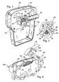
- FIG. 1perspectively illustrate the curvilinear peristaltic pump 10 constructed in accordance with the present invention.
- the present pump 10is preferably used in conjunction with an administration set or tubing assembly 12 which is shown in Figure 9 and will be described in more detail below.
- the tubing assembly 12itself is provided with a novel and unique flow stop member or shut-off valve 14 of the present invention which is shown in Figures 11-14 and will also be described in more detail below.
- the present pump 10is adapted to facilitate the pumping of a liquid through the tubing assembly 12, and comprises a housing 16.
- the housing 16includes a front housing half 18a and a back housing half 18b which are rigidly attached to each other through the use of fasteners such as screws, though alternative attachment methods may also be employed in relation thereto.
- the front housing half 18ais provided with a keypad 20 and a visual display 22, the use of which will be discussed in more detail below.
- the back housing half 18bis provided with a removable door 24 for accessing a battery storage compartment within the interior of the housing 16.
- the front and back housing halves 18a, 18bare preferably fabricated from a plastic material, though alternative lightweight materials may be used for the fabrication thereof.
- the housing 16comprises a support member 25 which defines a channel having a generally U-shaped cross-sectional configuration.
- the support member 25is attached to the front and back housing halves 18a, 18b such that the channel defined thereby extends longitudinally between the upper ends of the front and back housing halves 18a, 18b.
- the pump 10further comprises a platen member 26 which is pivotally connected to the support member 25 of the housing 16 and moveable between an operative position (as shown in Figures 1-3, 7 and 8) and a non-operative position (as shown in Figure 6) relative thereto.
- the platen member 26defines an arcuate, generally concave inner surface 28.
- the platen member 26When the platen member 26 is in its operative position, it resides within the channel defined by the support member 25, with the inner surface 28 being shielded thereby. As best seen in Figures 6 and 7, the platen member 26 is provided with an over-the-center latch mechanism 30 on the end thereof opposite that pivotally connected to the support member 25.
- the latch mechanism 30is cooperatively engagable to a pair of latch pins 32 protruding from respective ones of opposed inner surfaces of the support member 25 into the channel defined therebetween. As will be recognized, the engagement of the latch mechanism 30 to the latch pins 32 maintains or locks the platen member 26 within its operative position.
- the pump 10includes a platen sensor 120 which is operable to detect when the platen member 26 is in its operative position.
- the platen sensor 120is a Hall effect sensor which comprises a magnet 122 disposed within the over-the-center latch mechanism 30 of the platen member 26.
- the platen sensor 120includes a magnetic field detector 124 which is disposed within the support member 25 in close proximity to one of the latch pins 32 protruding therefrom. The magnetic field detector 124 is oriented so as to be disposed directly adjacent the magnet 122 when the platen member 26 is moved to its operative position and the latch mechanism 30 engaged to the latch pins 32. The use of the platen sensor 120 will be discussed in more detail below.
- the pump 10further comprises a rotatable cam 34 which is disposed within the interior of the housing 16 and rotatably mounted to the support member 25. More particularly, the cam 34 is mounted to the support member 25 so as to be rotatable about an axis which extends through the approximate center of the concavity of the arcuate inner surface 28 of the platen member 26 when the platen member 26 is in its operative position.
- the rotation of the cam 34is facilitated by a drive unit 36 of the pump 10 which is also disposed within the interior of the housing 16 and attached to the support member 25.
- the drive unit 36is mechanically coupled to the cam 34 such that the activation of the drive unit 36 results in the concurrent rotation of the cam in a first direction (i.e., the counter-clockwise rotation of the cam 34 when observed from the perspective shown in Figure 7), and the deactivation of the drive unit 36 maintains the cam in a set position.
- the drive unit 36comprises a cam shaft 38 which extends from the cam 34. Attached to the cam shaft 38 is a worm gear 40 of the drive unit 36.
- the drive unit 36comprises a variable speed electric motor 42 which is attached to the support member 25 via a motor mount 44. Extending from the electric motor 42 is a rotatable motor shaft 46 which includes a worm 48 mounted thereto. The distal end of the motor shaft 46 is rotatably mounted within a bearing disposed within an aperture 50 extending through a portion of the motor mount 44. The worm 48 is itself cooperatively engaged to the worm gear 40.
- the engagement between the worm 48 and the worm gear 40results in the rotation of the cam 34 in the first direction upon the activation of the motor 42.
- Such engagementalso eliminates any rotation of the cam 34 upon the deactivation of the motor 42, the significance of which will be discussed in more detail below.
- the motor 42 of the pump 10is electrically connected to and powered by a multiple batteries which are stored within the interior of the housing 16 and accessible via the access door 24 provided on the back housing half 18b.
- the pump 10 of the present inventionfurther comprises a plurality of pump fingers 52 which are movably attached to the support member 25 and are arranged in side-by-side relation to each other so as to define an arcuate row.
- Each of the pump fingers 52has a first end 54 which is cooperatively engaged to the cam 34 and a second end 56 which is disposed in spaced relation to the platen member 26 when the same is in its operative position.
- the pump 10also includes a pliable membrane 126 which is preferably fabricated from a transparent or translucent material and is attached to the support member 25 so as to cover the second ends 56 of the pump fingers 52. Importantly, the membrane 126 functions to prevent any moisture from leaking into the interior of the housing 16.
- each- of the pump fingers 52preferably includes a plurality of roller members 58 rotatably mounted within and protruding from the first end 54 thereof.
- the roller members 58 of each pump finger 52are arranged in a row.
- the pump fingers 52are cooperatively engaged to the cam 34 via the roller members 58. As will be recognized, since the roller members 58 freely roll on the camming surfaces of the cam 34, wear on such camming surfaces is substantially reduced.
- the present pump 10further comprises a motor speed control unit 60 which is operable to selectively increase and decrease the rotational speed of the cam 34 at prescribed intervals for reasons which will be discussed in more detail below.
- the motor speed control unit 60is disposed within the interior of the housing 16 and comprises an optical sensor 62 which is attached to the motor mount 44 and electrically connected to the motor 42.
- the optical sensor 62is adapted to transmit a beam of light L and sense any interruptions therein.
- the optical sensor 62includes a light beam transmitter 64 which is adapted to generate the beam of light L, and a light beam receiver 66 which is adapted to receive or sense the beam of the light L generated by the light beam transmitter 64.
- the motor speed control unit 60comprises a shutter or encoder wheel 68 which is attached to the cam shaft 38 and rotatable thereby.
- the optical sensor 62 and encoder wheel 68collectively define an optical encoder.
- the encoder wheel 68includes four (4) encoder arms 70 extending radially therefrom in equidistantly spaced intervals of approximately 90 degrees.
- the encoder wheel 68is oriented relative to the optical sensor 62 such that the encoder arms 70 will intermittently interrupt the beam of light L during the rotation of the encoder wheel 68 by the cam shaft 38.
- the number and size of the encoder arms 70is selected such that interruptions in the beam of light L caused thereby correspond to pump cycles of the pump 10, with the optical sensor 62 being operable to determine the beginning and end of each pump cycle and increase the power to the motor 42 and hence the rotational speed of the cam 34 between pump cycles.
- the pump 10further comprises a plurality of pinch members 72 which are movably attached to respective ones of the pump fingers 52 and protrude from the second ends 56 thereof.
- each of the pump fingers 52is provided with a transverse slot 74 which is disposed within the second end 56 thereof and transitions into a transverse cavity 76 therewithin.
- Each of the pinch members 72preferably comprises a base portion 78 which is disposed within the transverse cavity 76 and a finger portion 80 which extends from the base portion 78 into the transverse slot 74.
- the finger portion 80defines a finger tip 82 which protrudes from the second end 56 of a respective one of the pump fingers 52.
- a biasing spring 84 of the pinch member 72Extending between the base portion 78 and the wall of the respective transverse cavity 76 disposed furthest from the finger portion 80 is a biasing spring 84 of the pinch member 72.
- the biasing springs 84function to bias the pinch members 72 radially outwardly toward the inner surface 28 of the platen member 26 when the platen member 26 is in its operative position for reasons which will also be discussed in more detail below.
- the present pump 10further comprises a pair of pressure sensor members 86a, 86b, portions of which protrude from the support member 25 adjacent respective ends of the row of pump fingers 52.
- Each of the pressure sensor members 86a, 86bincludes a beam 87 having a strain gauge disposed thereon. The functionality of the pressure sensor members 86a, 86b will also be described in more detail below.
- the pump 10 constructed in accordance with the present inventionis preferably used in conjunction with the tubing assembly 12 which is releasably attachable to the support member 25 of the housing 16.
- the tubing assembly 12comprises a length of substantially straight, resilient tubing 88 which is preferably fabricated from polyvinyl chloride (PVC). Attached to each of the opposed ends of the tubing 88 are respective ones of a pair of connectors 90, such as standard Luer connectors. Additionally, attached to the tubing 88 is a tubing locator pin 92 (shown in Figure 10) and the shut-off valve 14 (shown in Figures 11-14) which is operable to selectively obstruct the flow of liquid through the tubing.
- PVCpolyvinyl chloride
- the tubing locator pin 92includes a generally C-shaped attachment portion 94 which is adapted to receive and frictionally engage the tubing 88 in a manner maintaining the tubing locator pin 92 in a desired location thereupon.
- the tubing locator pin 92includes a mounting portion 96 which is receivable into a complementary recess 98 formed within the support member 25 adjacent the location whereat the platen member 26 is pivotally connected thereto.
- the present pump 10further comprises a tubing sensor 128 which is disposed within the recess 98 formed within the support member 25.
- the tubing sensor 128is operable to detect when the tubing assembly 12 is properly engaged to the support member 25, and is tripped by the insertion of the tubing locator pin 92 into the recess 98.
- the shut-off valve 14 of the tubing assembly 12comprises a valve body 100.
- the valve body 100defines a first slot 102 extending longitudinally therethrough and a second slot 104 extending laterally therethrough in generally perpendicular or transverse relation to the first slot 102.
- the first and second slots 102, 104collectively form a generally T-shaped pattern within the valve body 100.
- the lower portion of the valve body 100is insertable into a complementary recess 105 formed within the support member 25 adjacent the end thereof opposite that including the recess 98 formed therein.
- the shut-off valve 14comprises a pinch arm 106 which has a generally H-shaped configuration and includes an opposed pair of side bar portions 108 which are interconnected by a cross bar portion 110 integrally connected thereto and extending generally perpendicularly therebetween.
- a post portion 112 of the pinch arm 106which has a generally cylindrical configuration.
- the post portion 112is sized having a length such that the distal end thereof protrudes beyond the lower ends of the side bar portions 108.
- a biasing spring 114 of the shut-off valve 14Disposed on the post portion 112 is a biasing spring 114 of the shut-off valve 14.
- the surface of the cross bar portion 110 opposite that having the post portion 112 extending therefrom and portions of the inner surfaces of the side bar portions 108collectively define an opening 116 of the pinch arm 106.
- the pinch arm 106when the pinch arm 106 is initially formed, the same is provided with a breakable detent tab 118 which is integrally connected to the lower end of one of the side bar portions 108, and thus is disposed adjacent the post portion 112. The use of the detent tab 118 will be described in more detail below.
- the valve body 100 of the shut-off valve 14, as well as the pinch arm 106 thereofmay be provided in shapes other than for those described above.
- the pinch arm 106In the shut-off valve 14, the pinch arm 106, including the biasing spring 114 mounted to the post portion 112, is movably attached to the valve body 100 via the receipt of the pinch arm 106 into the first slot 102.
- the pinch arm 106When the pinch arm 106 is properly inserted into the first slot 102, the upper ends of the side bar portions 108 thereof protrude from the upper end of the first slot 102 as seen in Figures 13 and 14, with the distal end of the post portion 112 extending into a reduced width section of the first slot 102 defined at the bottom end thereof. Additionally, the opening 116 defined by the pinch arm 106 is oriented so as to be in substantial alignment with the second slot 104 of the valve body 100.
- the detent tab 118engages the bottom end of the valve body 100 in a manner which maintains the biasing spring 114 in a state of compression and prevents the pinch arm 106 from reaching its maximum limit of upward travel.
- the shut-off valve 14is attached to the tubing 88 via the advancement of the tubing 88 through the second slot 104 and opening 116.
- the second slot 104 of the valve body 100is sized relative to the tubing 88 such that the wall of the tubing 88 and hence the lumen defined thereby is partially collapsed by the valve body 100 when the tubing 88 is advanced through the second slot 104 and opening 116.
- the compression of the tubing 88 by the valve body 100facilitates the frictional retention of the shut-off valve 14 at a prescribed location upon the tubing 88.
- the shut-off valve 14, and in particular its pinch arm 106is moveable between an open position (as shown in Figure 13) and a closed position (as shown in Figure 14).
- the pinch arm 106When the pinch arm 106 is in its open position, the wall of the tubing 88 passing through the shut-off valve 14 is only partially collapsed by the valve body 100 and not compressed by the pinch arm 106. As such, the wall of the tubing 88 continues to define an open lumen which allows for the flow of liquid through the tubing 88.
- the pinch arm 106when the pinch arm 106 is moved to its closed position, it acts against and applies compressive pressure to the wall of the tubing 88 in a manner completely collapsing the same and hence the lumen defined thereby.
- the complete collapse of the tubing 88 facilitated by the movement of the pinch arm 106 to its closed positionprevents the flow of liquid through the tubing 88. Since the tubing 88 is already partially collapsed by the passage thereof through the second slot 104, the total length of movement of the pinch arm 106 from its open position to its closed position whereat the tubing 88 is completely collapsed thereby is only about a few millimeters.
- the biasing spring 114normally biases the pinch arm 106 to its closed position.
- the movement of the pinch arm 106 to its open positionis accomplished by the application of pressure to the upper ends of the side bar portions 108 protruding from the upper end of the first slot 102 of the valve body 100 in an amount sufficient to overcome the biasing force exerted by the biasing spring 114 and move the pinch arm 106 toward the reduced width bottom end of the first slot 102.
- the shut-off valve 14 attached to the tubing 88is preferably maintained in its open position during shipment so as not to cause any premature permanent deformation in the tubing 88.
- the engagement of the detent tab 118 against the valve body 100maintains the pinch arm 106 in its open position in the manner shown in Figure 13.
- the detent tab 118is fractured or broken away from the remainder of the pinch arm 106 by twisting it approximately ninety degrees, thus causing the pinch arm 108 to immediately assume its normally closed position relative to the tubing 88 as shown in Figure 14.
- the mounting portion 96 of the tubing locator pin 92is removably insertable into the recess 98 of the support member 25, with the lower portion of the valve body 100 of the shut-off valve 14 being removably insertable into the recess 105 of the support member 25.
- the recesses 98, 105are formed within the support member 25 outwardly of each of the opposed ends of the row of pump fingers 52.
- tubing locator pin 92 and the shut-off valve 14are attached to the tubing 88 at locations whereat a portion of the tubing 88 is extended over the membrane 126, and hence the second ends 56 of the pump fingers 52 (including the finger tips 82 protruding therefrom), when the tubing locator pin 92 and shut-off valve 14 are removably inserted into their respective recesses 98, 105.
- the tubing locator pin 92 and the shut-off valve 14 of the tubing assembly 12are removably insertable into their respective recesses 98, 105 when the platen member 26 is in its non-operative position.
- the portion of the tubing 88 of the tubing assembly 12 extended over the second ends 56 of the pump fingers 52 by the insertion of the tubing locator pin 92 and the shut-off valve 14 into their respective recesses 98, 105is captured between the second ends 56 (including the fingertips 82 of the pinch members 72 protruding therefrom) and the inner surface 28 when the platen member 26 is moved to its operative position.
- tubing locator pin 92 and shut-off valve 14may be added or attached to lengths of resilient tubing of differing diameters. Additionally, the use of off-the-shelf straight line, continuous PVC tubing in the present tubing assembly 12 as opposed to a segment of silicone tubing having segments of PVC tubing mechanically secured thereto as is required by many prior art peristaltic pumps substantially reduces the costs associated with the present tubing assembly 12, in addition to providing increased reliability thereto due to the absence of any mechanical joints therein.
- the membrane 126need not necessarily be included in the pump 10, and that the tubing 88 may be extended directly over the second ends 56 of the pump fingers 52 and fingertips 82 of the pinch members 72.
- the pump 10is used by initially moving the platen member 26 to its non-operative position as shown in Figure 6. Thereafter, the tubing assembly 12 is releasably attached to the pump 12 via the insertion of the mounting portion 96 of the tubing locator pin 92 into the recess 98, and the insertion of the lower portion of the valve body 100 of the shut-off valve 14 into the recess 105.
- shut-off valve 14 and tubing locator pin 92are attached to the tubing 88 of the tubing assembly 12 at locations whereat the insertion thereof into respective ones of the recesses 98, 105 results in a portion of the tubing 88 being extended over the second ends 56 of the pump fingers 52 (including the finger tips 82 of the pinch members 72 protruding therefrom).
- the insertion of the tubing locator pin 92 into the recess 98also results in the tripping of the tubing sensor 128.
- a segment of the tubing 88 extending between the pump fingers 52 and shut-off valve 14rests upon one of the pressure sensor members 86, with a segment of the tubing 88 extending between the pump fingers 52 and the tubing locator pin 92 resting upon the other pressure sensor member 86.
- the shut-off valve 14 thereofresides in its normal closed position, with the pinch arm 106 thereof being engaged to and completely collapsing the tubing 88.
- the platen member 26is moved from its non-operative position to its operative position as shown in Figure 7. As indicated above, the movement of the platen member 26 to its operative position and engagement of the latch mechanism 30 thereof to the latch pins 32 results in the tripping of the platen sensor 120. When moved to its operative position, the inner surface 28 of the platen member 26 applies a slight amount of compressive pressure to that portion of the tubing 88 extending between the shut-off valve 14 and tubing locator pin 92.
- the portion of the tubing 88 which is extended over the row of pump fingers 52is slightly compressed between the inner surface 28 of the platen member 26 and second ends 56 of the pump fingers 52, including the finger tips 82 of the pinch member 72 protruding therefrom.
- the pump fingers 52, and more particularly the roller members 58 disposed within the second ends 56 thereof,are biased against the cam 34.
- the platen member 26is sized and configured to move the pinch arm 106 of the shut-off valve 14 from its normal closed position to its open position when the platen member 26 is moved to its operative position.
- a portion of the platen member 26acts against and applies pressure to the upper ends of the side bar portions 108 of the pinch arm 106, thus facilitating the compression of the biasing spring 114 and resultant movement of the pinch arm 106 to its open position.
- the platen member 26is pivotally connected to the support member 25 at a location whereat the movement of the platen member 26 from its non-operative position to its operative position results in the occlusion of the tubing 88 by at least one of the pinch members 72, and more particularly the finger tip 82 thereof, prior to the movement of the pinch arm 106 of the shut-off valve 14 from its closed position to its open position by the engagement of the platen member 26 thereagainst.
- the tubing 88is always occluded by either the shut-off valve 14 or one of the pinch members 72, thus effectively preventing any backflow of liquid therethrough.
- the pump 10may be activated to facilitate the pumping of liquid through the tubing assembly 12 thereby.
- the ability to activate the pump 10occurs as a result of both the tubing sensor 128 and platen sensor 120 being tripped by the interface of the tubing assembly 12 to the support member 25 and the closure of the platen member 26 (i.e., the movement of the platen member 26 to its operative position).
- both the platen and tubing sensors 120, 128are electrically connected to each other in series, both must be tripped in order for the pump 10, and in particular the drive unit 36 thereof, to be activated.
- the cam 34is configured to sequentially move the pump fingers 52 radially outwardly toward and inwardly away from the inner surface 28 of the platen member 26 when rotated in the first direction by the drive unit 36.
- the pump fingers 52are sequentially extended and retracted in a wave-like fashion as observed from the perspective shown in Figure 7, thus forcing liquid in the tubing 88 in the direction of rotation of the cam 34 (i.e., in a direction away from the end of the platen member 26 pivotally connected to the support member 25).
- the rotation of the cam 34forces liquid through the tubing 88 in the direction of cam rotation, with the occlusion of the tubing 88 which occurs as a result of the sequential action of the outwardly biased pinch members 72 thereagainst preventing any backflow of liquid within the tubing 88 when the platen member 26 is in its operative position, even upon the deactivation of the motor 42.
- the sequential movement of the first through the last pump fingers 52 of the row toward and away from the platen member 26 by the rotation of the cam 34defines a "pump cycle".
- the engagement of the second ends 56 of the pump fingers 52 and pinch members 72 against the tubing 88 in the above-described mannerforces liquid therethrough.
- the pump cyclesare generated in a generally sinusoidal fashion, with each of the pump cycles being separated by a "dead pump phase" wherein no liquid is being forced through the tube of the pump.
- the flow rate of liquid through the tube of the prior art rotary peristaltic pumpis not constant, but rather undergoing almost continuous changes in velocity.
- the cam 34is profiled or shaped so as to act against the roller members 58 protruding from the first ends 54 of the pump fingers 52 in a manner causing the second ends 56 and pinch members 72 to engage the tubing 88 such that the flow rate of liquid therethrough is substantially constant throughout each pump cycle.
- Such constant flow rateis achieved by forming the cam 34 as a four lobe cam.
- the motor speed control unit 60 of the pump 10is operable to increase the rotational speed of the cam 34 in the first direction between pump cycles for purposes of substantially eliminating the dead pumping phase which normally exists between pump cycles.
- the number and size of the encoder arms 70 of the encoder wheel 68is selected such that interruptions in the beam of light L caused thereby correspond to the pump cycles, with the optical sensor 62 being operable to determine the beginning and end of each pump cycle and increase the power to the motor 42 and hence the rotational speed of the cam 34 between pump cycles which substantially reduces the dead pump phase.
- an additional four (4) volts of poweris supplied to the motor 42 to achieve the desired level of increased rotational speed of the cam 34.
- FIG 16there is depicted an electrical schematic of the control circuit which functions as a closed loop feedback system and is used to facilitate the operational interface between the motor speed control unit 60 and drive unit 36 of the present pump 10.
- a full schematic of the control circuitis included in the present specification and illustrated below.
- a speedup cyclehas been implemented in the pump 10 to make its pump flow rate much more uniform by speeding up the pump rate during the dead zone portion of the pump cycle so that fluid flow is nearly constant, even at low flow rates.
- the speedup cycleis carefully tailored to minimize the acceleration command applied to the motor drive circuitry of the electric motor 42 in order to reduce the power spike caused by a sudden increase in the speed of the electric motor 42.
- a simple low pass filterwould not be adequate due to the large speed change rate involved in the pump 10. Since for a simple RC time constant the initial speed change is greatest, with the rate asymptotically approaching final value, a linear ramped response is required to facilitate a constant acceleration of the electric motor 42 and reduce motor current power spikes. More particularly, a speed-up signal is required which starts from an initial commanded rate, ramps up to a speed-up rate, and then returns to a programmed rate.
- the optical sensor 62 of the motor speed control unit 60is used to generate a signal when speedup is required.
- the motor speedup signal generated by the optical sensor 62is recovered and amplified to digital logic levels.
- the circuitalso includes a gated temperature compensated current source and an integrated circuit which is a 4 to 1 analog multiplexer.
- the circuitgenerates a pulse width modulated (PWM) signal which enters the control input to the switch. During the "1" input, the switch is at ground. When the input is at "0", the switch is at a precision +2.5 volts.
- PWMpulse width modulated
- the switchinverts the PWM signal and level converts it to a precision voltage for the proper input command to the driver of the electric motor 42.
- the input or motor speed commandgoes through a resistor and a capacitor, and is converted to a drive command.
- the same PWM signalis also sent through a resistor and a capacitor to recover the input command level to interact with the gated current generator.
- the circuitalso includes a unity gain buffer amplifier to provide drive requirements for the switch.
- the speedup signalis at a much lower frequency than the 10 kHz PWM signal, and passes on to the electric motor 42 through a resistor when gated on.
- the pressure sensor members 86a and 86bgenerate electrical signals corresponding to the degree of expansion or compression, respectively, of the tubing 88 when acted upon by the pump fingers 52 and pinch members 72, thus providing warning of any over expansion and/or compression thereof.
- the shut-off valve 14returns to its normal closed position and prevents any backflow of liquid through the tubing 88 in a direction opposite the first direction of rotation of the cam 34.
- the pump 10 of the present inventionis provided with an internal monitor and control unit 130 which monitors, controls and coordinates the various operations thereof.
- the monitor and control unit 130implements software of a specific design and architecture which imparts to the pump 10 various functional attributes not found in prior art peristaltic pumps.
- the monitor and control unit 130is in electrical communication with a number of components of the pump 10, including the previously described key pad 20 which has an 19 key configuration. Included in the key pad 20 is an on/off key and a remote bolus button for the input of status and data to the software of the pump 10. Also in electrical communication with the monitor and control unit 130 is a beeper 132 of the pump 10 which is disposed within the interior of the housing 16.
- the beeper 132contains two buzzers which operate at a single, fixed frequency.
- One of the buzzerswhich is designated as the normal operation buzzer, is pulsed at varying widths, pulse rates and total number of pulses, as a function of the event to be signaled thereby.
- the second buzzerwhich is designated as the auxiliary buzzer, operates from a watch dog time out. The second buzzer can be tested once and then reset via a clear auxiliary beeper input event.
- the system clock 134is a processor timer interrupt which is set at approximately 53.3 milliseconds.
- the display 22preferably consists of a 100 x 32 dot graphical LCD display and three individual LED's which are located on the key pad 20.
- the LCD displayis used to provide data information to the user, with the LED's being used to provide status information to the user.
- various pump sensorsare in electrical communication with the monitor and control unit 130, including the above-described pressure sensor members 86, platen sensor 120, and tubing sensor 128.
- the pump 10may also be provided with air in-line sensors at the beginning and end of that portion of the tubing 88 extending over the membrane 126, and peristaltic cam drive sensors which monitor the revolution or rotation of the cam 34.
- the electric motor 42 of the drive unit 36is also in electrical communication with the monitor and control unit 130, as is a power supply 136 of the pump 10.
- the electric motor 42facilitates the rotation of the cam 34, and hence drives the pump 10.
- the power supply 136may comprise one or more batteries which are stored within the interior of the housing 16, such as a 3- volt battery or a lithium battery.
- the power supply 136may comprise a 3-volt external power source which is electrically connected to the housing 16 and placed into electrical communication with the necessary components of the pump 10.
- a system memory 138also in electrical communication with the monitor and control unit 130 is a system memory 138, a real time clock 140, a watch dog 142, and a serial communications port 144.
- the real time clock 140provides a reference for the date and time of day, with this information being read therefrom on demand.
- the real time clock 140may be reset to a pre-programmed value.
- the serial communications port 144is preferably an asynchronous serial port, 9600 bps full duplex, with no RTS or CTS, RXD and TXD only.
- the watch dog 142is an independent, re-triggered one shot which is attached to a mirocontroller NMI input and a motor inhibit control input of the pump 10.
- the watch dog 142must be "petted” at least once per 1.6 seconds, and also provides a test capability which can be activated to cause the watch dog 142 to time out but not reset the microcontroller of the pump 10 one time after the power-up thereof.
- the monitor and control unit 130 of the pump 10controls the infusion process and monitors the process to prevent over infusion.
- the monitor and control unit 130also provides for the user selection and programming of five different therapies, including:
- the pump 10can be used for intravenous, intra-arterial, epidural, subcutaneous, or enteral therapies.
- the pump 10can also be used to deliver medications from a medication reservoir, from IV bags, or from syringes.
- a "validate pump process”implemented by the software initiates the operation of the monitor and control unit 130, and more particularly the software thereof.
- the validate pump processperforms a number of functions, including a "boot” which is entered from power-up reset and initializes the monitor and control unit 130 and the input/outputs thereof to the proper configuration.
- the bootperforms a test on the boot code and start-up code of the software to verify their validity, and also is able to accept a special command to download code to a flash ROM.
- the bootalso verifies that a valid program is downloaded into the flash ROM before operation of the pump 10 is permitted to proceed.
- the bootwill also first verify via a CRC algorithm that the boot code is good.
- the validate pump processperforms a "start-up" which verifies that the pump 10, including both its hardware and software, is functioning properly by performing the required start tests on the monitor and control unit 130, system memory 138, pump monitor sensors 86, 120, 124, drive unit 36, and all aspects of the hardware of the pump 10. If these tests pass, control will transfer to a "program select" function of the validate pump process, otherwise it will transfer to a malfunction phase.
- the program select function of the validate pump processprovides a means to the user for selecting normal pump operation (transfer to programming), or allowing the user to perform special set-up functions. Access to such special set-up functions requires a special access code by the user, with such set-up transferring directly to the normal operation of the pump 10. These special set-up functions include printing the history files and other pertinent data of a patient.
- a further function of the validate pump processis "factory calibration" which provides for the calibration of the pump 10. These functions are also accessed only by a special access code, and are manually commanded.
- the software of the monitor and control unit 130also implements a "create therapy process" which accepts inputs from the user for programming up to five (5) different infusion therapies.
- Such programmingincludes the selection of the therapy to be programmed, the programming of the pump 10 and therapy options, and the programming of the prescription for the infusion.
- a therapymay be programmed as a new therapy, a repeat of an existing therapy, changes in an existing therapy, or continue with a therapy in process which was previously interrupted. After a therapy has been validated by requiring the user to select each prescription parameter with the push of the yes key of the key pad 20, execution will transfer to a notification menu to allow the start of the infusion.
- the pump 10 embodying the present inventionincludes numerous other operational attributes which are implemented by various aspects of its hardware and software.
Landscapes
- Engineering & Computer Science (AREA)
- Health & Medical Sciences (AREA)
- Mechanical Engineering (AREA)
- General Engineering & Computer Science (AREA)
- Hematology (AREA)
- Anesthesiology (AREA)
- Biomedical Technology (AREA)
- Heart & Thoracic Surgery (AREA)
- Vascular Medicine (AREA)
- Life Sciences & Earth Sciences (AREA)
- Animal Behavior & Ethology (AREA)
- General Health & Medical Sciences (AREA)
- Public Health (AREA)
- Veterinary Medicine (AREA)
- Reciprocating Pumps (AREA)
- Saccharide Compounds (AREA)
Abstract
Description
Claims (20)
- A curvilinear peristaltic pump (10), comprising:characterised by:a housing (16) including a support member (25) having first and secondrecesses disposed therein;a platen member (26) attached to the housing;a rotatable cam (34) disposed within the housing;a drive unit (36) disposed within the housing and mechanically coupled to thecam, the activation of the drive unit resulting in the concurrent rotation of the cam inthe first direction;a plurality of pump fingers (52) movably attached to the housing, each of thepump fingers (52) having a first end (54) which is co-operatively engaged to the camand a second end (56) which is disposed in spaced relation to the platen member,the cam being configured to sequentially move the pump fingers radially outwardlytoward and inwardly away from the platen member when rotated in the first directionby the drive unit; anda tubing assembly (12) releasably attachable to the housing and comprising:a length of resilient tubing (88);wherein the tubing locator pin and the shut-off valve are attached to thetubing at locations whereat a portion of the tubing is extended over the second ends(56) of the pump fingers when the tubing locator pin and the shut-off valve areremovably inserted into respective ones of the first and second recesses within thesupport member of the housing, the tubing being extensible between the secondends and the platen member such that the sequential movement of the pump fingerstoward and away from the platen member results in liquid within the tubing beingpumped in the first direction of rotation of the cam.a tubing sensor (128) disposed within the first recess (98)a tubing locator pin (92) attached to the tubing and removably insertable intothe first recess and operable to trip the tubing sensor (128); anda shut-off valve (14) attached to the tubing and removably insertable into thesecond recess, the shut-off valve being operable to selectively obstruct the flow ofliquid through the tubing in a direction opposite the first direction;
- The pump of Claim 1 wherein the tubing of the tubing assembly is fabricatedfrom polyvinyl chloride.
- The pump of Claim 1 or 2 further comprising a pliable membrane (126) whichis attached to the housing and covers the second ends of the pump fingers.
- The pump of Claim 3 wherein:the platen member (26) defines an arcuate, generally concave inner surface(28) and is pivotally connected to the housing so as to be movable between anoperative position whereat the membrane is covered thereby and the second endsof the pump fingers are disposed in substantially equidistantly spaced relation to theinner surface, and a non-operative position whereat the membrane is exposed;the tubing locator pin (92) and the shut-off valve (14) of the tubing assemblybeing removably insertable into respective ones of the first and second recesseswithin the support member of the housing when the platen member is in the non-operativeposition, with the portion of the tubing extended over the membrane by theinsertion of the tubing locator pin and the shut-off valve into respective ones of thefirst and second recesses being captured between the membrane and the innersurface when the platen member is in the operative position.
- The pump of Claim 4 wherein the shut-off valve (14) comprises:a valve body having an opening therein for permitting the passage of thetubing therethrough; anda pinch arm movably attached to the valve body and engageable to thetubing passing through the opening;the pinch arm being movable between an open position whereat the tubingpassing through the valve body is not compressed by the pinch arm which allowsthe flow of liquid through the tubing, and a closed position whereat the tubingpassing through the valve body is collapsed by the pinch arm which prevents theflow of liquid through the tubing.
- The pump of Claim 5 wherein:the shut-off valve (14) further includes a biasing member for normally biasingthe pinch arm to the closed position;the movement of the platen member to the operative position facilitating themovement of the pinch arm from the closed position to the open position.
- The pump of Claim 6 wherein the biasing member comprises a spring whichextends between the valve body and the pinch arm.
- The pump of Claim 6 or 7 wherein the pinch arm includes a breakable detenttab formed thereon which maintains the pinch arm in the open position, the removalof the detent tab from the pinch arm resulting in the movement of the pinch arm tothe closed position.
- The pump of Claim 6, 7 or 8 further comprising a plurality of pinch members(72) movably attached to respective ones of the pump fingers and protruding from the second ends thereof, each of the pinch members being biased radially outwardlytoward the inner surface of the platen member and operable to substantially occludethe tubing when the pump finger to which it is attached is moved radially outwardlyto a position closest to the inner surface.
- The pump of Claim 9 wherein the platen member is pivotally connected tothe housing at a location whereas the movement of the platen member from thenon-operative position to the operative position results in the occlusion of the tubingby at least one of the pinch members prior to the movement of the pinch arm of theshut-off valve from the closed position to the open position by the platen member.
- The pump of Claim 4 further comprising:a platen sensor (120) disposed within the housing and operable to detectwhen the platen member is in the operative position; anda tubing sensor disposed within the housing and operable to detect when thetubing is extended over the membrane;the tubing sensor being tripped by the insertion of the tubing locator pin intothe first recess within the support member of the housing, with the platen sensorbeing tripped by the movement of the platen member to the operative position.
- The pump of Claim 11 wherein the platen sensor (120) and the tubing sensorelectrically communicate with each other in a manner wherein the drive unit may notbe activated until the tubing locator pin is inserted into the first recess within thesupport member of the housing and the platen member is in the operative position.
- The pump of Claim 12 wherein the platen sensor is a Hall effect sensorcomprising:a magnet which is disposed within the platen member, andmagnetic field detector which is disposed within the housing;the magnet and the magnetic field detector being oriented so as to bedisposed directly adjacent each other when the platen member is in the operativeposition.
- The pump of any preceding claim wherein the pump fingers (52) arearranged in a row and the pump further comprises a pair of pressure sensormembers (86a) disposed within the support member of the housing adjacentrespective ones of the row of pumping fingers for engaging the tubing andgenerating electrical signals corresponding to the degree of compression thereof.
- A tubing assembly (12) for use in a peristaltic pump (10) having a housing(16) defining a support member (25) which includes first and second recessesdisposed therein, a tubing sensor (128) disposed within the first recess (98), a platen member (26) attached to the housing, a rotatable cam (34) disposed within the housing, and a plurality of pump fingers (52) movablyattached to the housing and co-operatively engaged to the cam such that therotation of the cam sequentially moves the pump fingers outwardly toward andinwardly away from the platen member, the tubing assembly comprising:characterised by:a length of resilient tubing (88);wherein the tubing locator pin and the shut-off valve are attached to thetubing at locations whereat a portion of the tubing is extended over the pump fingerswhen the tubing locator pin and the shut-off valve are removably inserted intorespective ones of the first and second recesses within the support member of thehousing.a tubing locator pin (92) attached to the tubing and removably insertable intothe first recess and operable to trip the tubing sensor (128); anda shut-off valve (14) attached to the tubing and removably insertable into thesecond recess, the shut-off valve being operable to selectively obstruct the flow ofliquid through the tubing;
- The tubing assembly of Claim 15 wherein the tubing of the tubing assemblyis fabricated from polyvinyl chloride.
- The tubing assembly of Claim 15 or 16 wherein the shut-off valve comprises:a valve body having an opening therein for permitting the passage of thetubing therethrough; anda pinch arm movably attached to the valve body and engageable to thetubing passing through the opening;the pinch arm being movable between an open position whereat the tubingpassing through the valve body is collapsed by the pinch arm.
- The tubing assembly of Claim 17 wherein the shut-off valve further includesa biasing member for normally biasing the pinch arm to the closed position.
- The tubing assembly of Claim 18 wherein the biasing member comprises aspring which extends between the valve body and the pinch arm.
- The tubing assembly of Claim 18 or 19 wherein the pinch arm includes abreakable detent tab formed thereon which maintains the pinch arm in the openposition, the removal of the detent tab from the pinch arm resulting in the movementof the pinch arm to the closed position.
Applications Claiming Priority (3)
| Application Number | Priority Date | Filing Date | Title |
|---|---|---|---|
| US189052 | 1998-11-09 | ||
| US09/189,052US6164921A (en) | 1998-11-09 | 1998-11-09 | Curvilinear peristaltic pump having insertable tubing assembly |
| PCT/US1999/026336WO2000028217A1 (en) | 1998-11-09 | 1999-11-08 | Curvilinear peristaltic pump |
Publications (3)
| Publication Number | Publication Date |
|---|---|
| EP1135609A2 EP1135609A2 (en) | 2001-09-26 |
| EP1135609A4 EP1135609A4 (en) | 2002-07-03 |
| EP1135609B1true EP1135609B1 (en) | 2004-03-24 |
Family
ID=22695710
Family Applications (1)
| Application Number | Title | Priority Date | Filing Date |
|---|---|---|---|
| EP99956956AExpired - LifetimeEP1135609B1 (en) | 1998-11-09 | 1999-11-08 | Curvilinear peristaltic pump |
Country Status (7)
| Country | Link |
|---|---|
| US (2) | US6164921A (en) |
| EP (1) | EP1135609B1 (en) |
| AT (1) | ATE262648T1 (en) |
| AU (1) | AU1345100A (en) |
| DE (1) | DE69915869T2 (en) |
| IL (1) | IL143021A (en) |
| WO (1) | WO2000028217A1 (en) |
Families Citing this family (196)
| Publication number | Priority date | Publication date | Assignee | Title |
|---|---|---|---|---|
| US9023031B2 (en) | 1997-08-13 | 2015-05-05 | Verathon Inc. | Noninvasive devices, methods, and systems for modifying tissues |
| FR2790041B1 (en)* | 1999-02-23 | 2002-01-18 | Fresenius Vial | METHOD FOR CONTROLLING A PUMPING DEVICE COMPRISING A PUMP PROVIDED WITH A FLEXIBLE TUBE AND DEVICE FOR IMPLEMENTING THE METHOD |
| US7306591B2 (en) | 2000-10-02 | 2007-12-11 | Novasys Medical, Inc. | Apparatus and methods for treating female urinary incontinence |
| EP1815879A3 (en) | 2001-05-18 | 2007-11-14 | Deka Products Limited Partnership | Infusion set for a fluid pump |
| US7613491B2 (en) | 2002-05-22 | 2009-11-03 | Dexcom, Inc. | Silicone based membranes for use in implantable glucose sensors |
| US8364229B2 (en) | 2003-07-25 | 2013-01-29 | Dexcom, Inc. | Analyte sensors having a signal-to-noise ratio substantially unaffected by non-constant noise |
| US7553295B2 (en) | 2002-06-17 | 2009-06-30 | Iradimed Corporation | Liquid infusion apparatus |
| US20040064435A1 (en)* | 2002-07-26 | 2004-04-01 | Ahmad-Maher Moubayed | Clinical assessment and diagnostic tool for use with peristaltic pump |
| US7565301B2 (en)* | 2002-07-26 | 2009-07-21 | Curlin Medical Inc. | System and method for remotely operating a peristaltic pump |
| US20050267401A1 (en)* | 2004-05-25 | 2005-12-01 | Sherwood Services, Ag. | Safety interlock system for an enteral feeding pump |
| IL152865A0 (en)* | 2002-11-14 | 2003-06-24 | Q Core Ltd | Peristalic pump |
| US9763609B2 (en) | 2003-07-25 | 2017-09-19 | Dexcom, Inc. | Analyte sensors having a signal-to-noise ratio substantially unaffected by non-constant noise |
| US8626257B2 (en) | 2003-08-01 | 2014-01-07 | Dexcom, Inc. | Analyte sensor |
| US9135402B2 (en) | 2007-12-17 | 2015-09-15 | Dexcom, Inc. | Systems and methods for processing sensor data |
| US20080119703A1 (en) | 2006-10-04 | 2008-05-22 | Mark Brister | Analyte sensor |
| US7591801B2 (en) | 2004-02-26 | 2009-09-22 | Dexcom, Inc. | Integrated delivery device for continuous glucose sensor |
| US8886273B2 (en) | 2003-08-01 | 2014-11-11 | Dexcom, Inc. | Analyte sensor |
| US20190357827A1 (en) | 2003-08-01 | 2019-11-28 | Dexcom, Inc. | Analyte sensor |
| US7920906B2 (en) | 2005-03-10 | 2011-04-05 | Dexcom, Inc. | System and methods for processing analyte sensor data for sensor calibration |
| US9247900B2 (en) | 2004-07-13 | 2016-02-02 | Dexcom, Inc. | Analyte sensor |
| US8425416B2 (en) | 2006-10-04 | 2013-04-23 | Dexcom, Inc. | Analyte sensor |
| US8425417B2 (en) | 2003-12-05 | 2013-04-23 | Dexcom, Inc. | Integrated device for continuous in vivo analyte detection and simultaneous control of an infusion device |
| US8364230B2 (en) | 2006-10-04 | 2013-01-29 | Dexcom, Inc. | Analyte sensor |
| US8287453B2 (en) | 2003-12-05 | 2012-10-16 | Dexcom, Inc. | Analyte sensor |
| US8364231B2 (en) | 2006-10-04 | 2013-01-29 | Dexcom, Inc. | Analyte sensor |
| US8423114B2 (en) | 2006-10-04 | 2013-04-16 | Dexcom, Inc. | Dual electrode system for a continuous analyte sensor |
| US11633133B2 (en) | 2003-12-05 | 2023-04-25 | Dexcom, Inc. | Dual electrode system for a continuous analyte sensor |
| WO2009048462A1 (en) | 2007-10-09 | 2009-04-16 | Dexcom, Inc. | Integrated insulin delivery system with continuous glucose sensor |
| US8808228B2 (en) | 2004-02-26 | 2014-08-19 | Dexcom, Inc. | Integrated medicament delivery device for use with continuous analyte sensor |
| CN101655083B (en)* | 2004-05-14 | 2016-02-03 | 弗雷森纽斯医疗护理德国有限责任公司 | Roller pump |
| US7794423B2 (en) | 2004-05-25 | 2010-09-14 | Covidien Ag | Re-certification system for a flow control apparatus |
| US7462170B2 (en) | 2004-05-25 | 2008-12-09 | Covidien Ag | Administration feeding set and valve mechanism |
| US8961461B2 (en) | 2004-05-27 | 2015-02-24 | Baxter International Inc. | Multi-state alarm system for a medical pump |
| FR2872553B1 (en)* | 2004-06-30 | 2006-09-22 | Millipore Corp | PERISTALTIC PUMP COMPRISING A SUPPORT MEMBER AND A BACK SUPPORT SUITABLE FOR COOPERATING WITH A TUBE |
| FR2872554B1 (en)* | 2004-06-30 | 2008-09-19 | Millipore Corp | PERISTALTIC PUMP COMPRISING TUBE POSITIONING BODIES |
| US20060009734A1 (en) | 2004-07-07 | 2006-01-12 | Martin James F | Dosage control for drug delivery system |
| US7654956B2 (en) | 2004-07-13 | 2010-02-02 | Dexcom, Inc. | Transcutaneous analyte sensor |
| US7783333B2 (en) | 2004-07-13 | 2010-08-24 | Dexcom, Inc. | Transcutaneous medical device with variable stiffness |
| US8886272B2 (en) | 2004-07-13 | 2014-11-11 | Dexcom, Inc. | Analyte sensor |
| IL165365A0 (en) | 2004-11-24 | 2006-01-15 | Q Core Ltd | Finger-type peristaltic pump |
| IL179228A0 (en)* | 2006-11-13 | 2007-03-08 | Q Core Ltd | An open/close mechanism of passive mechanical interface and a finger-type peristaltic infusion pump |
| US8308457B2 (en) | 2004-11-24 | 2012-11-13 | Q-Core Medical Ltd. | Peristaltic infusion pump with locking mechanism |
| US20060127247A1 (en)* | 2004-12-10 | 2006-06-15 | Hamilton Sundstrand Corporation | Magnetic pulse pump/compressor system |
| US7950908B2 (en)* | 2005-01-26 | 2011-05-31 | Seiko Epson Corporation | Fluid transporting device of a peristalic type with tube and push pin arrangement |
| JP3750689B1 (en)* | 2005-02-04 | 2006-03-01 | セイコーエプソン株式会社 | Fluid transport device and fluid transporter |
| US7722338B2 (en)* | 2005-02-10 | 2010-05-25 | Novasys Medical, Inc. | Peristaltic pump providing simplified loading and improved tubing kink resistance |
| US7556481B2 (en)* | 2005-08-26 | 2009-07-07 | Baxter International Inc. | Rotary axial peristaltic pumps and related methods |
| WO2007035654A2 (en)* | 2005-09-19 | 2007-03-29 | Lifescan, Inc. | Systems and methods for detecting a partition position in an infusion pump |
| US20070066940A1 (en)* | 2005-09-19 | 2007-03-22 | Lifescan, Inc. | Systems and Methods for Detecting a Partition Position in an Infusion Pump |
| US20070093753A1 (en)* | 2005-09-19 | 2007-04-26 | Lifescan, Inc. | Malfunction Detection Via Pressure Pulsation |
| US7534099B2 (en) | 2005-09-30 | 2009-05-19 | Covidien Ag | Aliquot correction for feeding set degradation |
| US7632249B2 (en) | 2005-10-28 | 2009-12-15 | Curlin Medical Inc. | Syringe assist for infusion pump |
| US8852148B2 (en)* | 2005-11-01 | 2014-10-07 | Curlin Medical Inc. | Infusion pump having function keys |
| JP3992058B2 (en) | 2005-11-16 | 2007-10-17 | セイコーエプソン株式会社 | Fluid transport device |
| JP4355722B2 (en)* | 2005-11-17 | 2009-11-04 | セイコーエプソン株式会社 | Fluid transport device |
| US11497846B2 (en) | 2006-02-09 | 2022-11-15 | Deka Products Limited Partnership | Patch-sized fluid delivery systems and methods |
| US12274857B2 (en) | 2006-02-09 | 2025-04-15 | Deka Products Limited Partnership | Method and system for shape-memory alloy wire control |
| US12370305B2 (en) | 2006-02-09 | 2025-07-29 | Deka Products Limited Partnership | Patch-sized fluid delivery systems and methods |
| US12151080B2 (en) | 2006-02-09 | 2024-11-26 | Deka Products Limited Partnership | Adhesive and peripheral systems and methods for medical devices |
| US11364335B2 (en) | 2006-02-09 | 2022-06-21 | Deka Products Limited Partnership | Apparatus, system and method for fluid delivery |
| US10010669B2 (en) | 2006-02-09 | 2018-07-03 | Deka Products Limited Partnership | Systems and methods for fluid delivery |
| US11478623B2 (en) | 2006-02-09 | 2022-10-25 | Deka Products Limited Partnership | Infusion pump assembly |
| EP3165247B1 (en) | 2006-02-09 | 2020-10-28 | DEKA Products Limited Partnership | Pumping fluid delivery systems and methods using force application assembley |
| US12070574B2 (en) | 2006-02-09 | 2024-08-27 | Deka Products Limited Partnership | Apparatus, systems and methods for an infusion pump assembly |
| US11027058B2 (en) | 2006-02-09 | 2021-06-08 | Deka Products Limited Partnership | Infusion pump assembly |
| US8025634B1 (en) | 2006-09-18 | 2011-09-27 | Baxter International Inc. | Method and system for controlled infusion of therapeutic substances |
| US8447376B2 (en) | 2006-10-04 | 2013-05-21 | Dexcom, Inc. | Analyte sensor |
| US8562528B2 (en) | 2006-10-04 | 2013-10-22 | Dexcom, Inc. | Analyte sensor |
| US8275438B2 (en) | 2006-10-04 | 2012-09-25 | Dexcom, Inc. | Analyte sensor |
| US8449464B2 (en) | 2006-10-04 | 2013-05-28 | Dexcom, Inc. | Analyte sensor |
| US8298142B2 (en) | 2006-10-04 | 2012-10-30 | Dexcom, Inc. | Analyte sensor |
| US8478377B2 (en) | 2006-10-04 | 2013-07-02 | Dexcom, Inc. | Analyte sensor |
| IL179231A0 (en) | 2006-11-13 | 2007-03-08 | Q Core Ltd | A finger-type peristaltic pump comprising a ribbed anvil |
| US8535025B2 (en) | 2006-11-13 | 2013-09-17 | Q-Core Medical Ltd. | Magnetically balanced finger-type peristaltic pump |
| IL179234A0 (en)* | 2006-11-13 | 2007-03-08 | Q Core Ltd | An anti-free flow mechanism |
| US8303275B2 (en)* | 2006-12-07 | 2012-11-06 | Seiko Epson Corporation | Micropump, tube unit, and control unit |
| US7654127B2 (en)* | 2006-12-21 | 2010-02-02 | Lifescan, Inc. | Malfunction detection in infusion pumps |
| CA2677667A1 (en) | 2007-02-09 | 2008-08-14 | Deka Products Limited Partnership | Automated insertion assembly |
| US7644299B2 (en)* | 2007-03-02 | 2010-01-05 | Proprietary Controls Systems Corporation | Fault tolerant security system, method and apparatus |
| US20200037874A1 (en) | 2007-05-18 | 2020-02-06 | Dexcom, Inc. | Analyte sensors having a signal-to-noise ratio substantially unaffected by non-constant noise |
| WO2008154312A1 (en) | 2007-06-08 | 2008-12-18 | Dexcom, Inc. | Integrated medicament delivery device for use with continuous analyte sensor |
| EP2173408A1 (en)* | 2007-06-27 | 2010-04-14 | Medingo Ltd. | Tubing for fluid delivery device |
| US8105282B2 (en) | 2007-07-13 | 2012-01-31 | Iradimed Corporation | System and method for communication with an infusion device |
| US8043077B2 (en)* | 2007-08-30 | 2011-10-25 | Seiko Epson Corporation | Micropump |
| US8417312B2 (en) | 2007-10-25 | 2013-04-09 | Dexcom, Inc. | Systems and methods for processing sensor data |
| WO2009073212A1 (en)* | 2007-12-05 | 2009-06-11 | Bunn-O-Matic Corporation | Peristaltic pump |
| US8290559B2 (en) | 2007-12-17 | 2012-10-16 | Dexcom, Inc. | Systems and methods for processing sensor data |
| US9026370B2 (en) | 2007-12-18 | 2015-05-05 | Hospira, Inc. | User interface improvements for medical devices |
| US9526830B2 (en) | 2007-12-31 | 2016-12-27 | Deka Products Limited Partnership | Wearable pump assembly |
| US9456955B2 (en) | 2007-12-31 | 2016-10-04 | Deka Products Limited Partnership | Apparatus, system and method for fluid delivery |
| US8881774B2 (en) | 2007-12-31 | 2014-11-11 | Deka Research & Development Corp. | Apparatus, system and method for fluid delivery |
| US10080704B2 (en) | 2007-12-31 | 2018-09-25 | Deka Products Limited Partnership | Apparatus, system and method for fluid delivery |
| US8900188B2 (en) | 2007-12-31 | 2014-12-02 | Deka Products Limited Partnership | Split ring resonator antenna adapted for use in wirelessly controlled medical device |
| US10188787B2 (en) | 2007-12-31 | 2019-01-29 | Deka Products Limited Partnership | Apparatus, system and method for fluid delivery |
| CA2919786C (en) | 2007-12-31 | 2019-10-22 | Deka Products Limited Partnership | Infusion pump assembly |
| US8986253B2 (en) | 2008-01-25 | 2015-03-24 | Tandem Diabetes Care, Inc. | Two chamber pumps and related methods |
| EP2252196A4 (en) | 2008-02-21 | 2013-05-15 | Dexcom Inc | Systems and methods for processing, transmitting and displaying sensor data |
| US8396528B2 (en) | 2008-03-25 | 2013-03-12 | Dexcom, Inc. | Analyte sensor |
| US20090281526A1 (en)* | 2008-05-09 | 2009-11-12 | Tyco Healthcare Group Lp | Negative Pressure Wound Therapy Apparatus Including a Fluid Line Coupling |
| US10406076B2 (en) | 2008-06-19 | 2019-09-10 | Alcor Scientific, Inc. | Enteral feeding pump system |
| JP5298699B2 (en)* | 2008-08-20 | 2013-09-25 | セイコーエプソン株式会社 | Control unit, tube unit, micro pump |
| US8408421B2 (en) | 2008-09-16 | 2013-04-02 | Tandem Diabetes Care, Inc. | Flow regulating stopcocks and related methods |
| CA2737461A1 (en) | 2008-09-19 | 2010-03-25 | Tandem Diabetes Care, Inc. | Solute concentration measurement device and related methods |
| JP5282508B2 (en)* | 2008-09-29 | 2013-09-04 | セイコーエプソン株式会社 | Control unit, tube unit, micro pump |
| US12186531B2 (en) | 2008-10-10 | 2025-01-07 | Deka Products Limited Partnership | Infusion pump assembly |
| US9180245B2 (en) | 2008-10-10 | 2015-11-10 | Deka Products Limited Partnership | System and method for administering an infusible fluid |
| US12370327B2 (en) | 2008-10-10 | 2025-07-29 | Deka Products Limited Partnership | Infusion pump methods, systems and apparatus |
| JP5195368B2 (en) | 2008-12-05 | 2013-05-08 | セイコーエプソン株式会社 | Tube unit, control unit, micro pump |
| US8353864B2 (en) | 2009-02-18 | 2013-01-15 | Davis David L | Low cost disposable infusion pump |
| US20100211002A1 (en)* | 2009-02-18 | 2010-08-19 | Davis David L | Electromagnetic infusion pump with integral flow monitor |
| US8197235B2 (en) | 2009-02-18 | 2012-06-12 | Davis David L | Infusion pump with integrated permanent magnet |
| WO2010133319A1 (en) | 2009-05-19 | 2010-11-25 | Fresenius Medical Care Deutschland Gmbh | Apparatus and method for identifying a tubing system for an extracorporeal blood treatment device |
| EP2448486B1 (en) | 2009-07-02 | 2021-08-25 | Dexcom, Inc. | Analyte sensors and methods of manufacturing same |
| WO2011008966A2 (en) | 2009-07-15 | 2011-01-20 | Deka Products Limited Partnership | Apparatus, systems and methods for an infusion pump assembly |
| EP2724739B1 (en) | 2009-07-30 | 2015-07-01 | Tandem Diabetes Care, Inc. | Portable infusion pump system |
| US8241018B2 (en) | 2009-09-10 | 2012-08-14 | Tyco Healthcare Group Lp | Compact peristaltic medical pump |
| US8371832B2 (en) | 2009-12-22 | 2013-02-12 | Q-Core Medical Ltd. | Peristaltic pump with linear flow control |
| US8142400B2 (en)* | 2009-12-22 | 2012-03-27 | Q-Core Medical Ltd. | Peristaltic pump with bi-directional pressure sensor |
| CA3033439C (en) | 2010-01-22 | 2021-04-06 | Deka Products Limited Partnership | Method and system for shape-memory alloy wire control |
| US9457158B2 (en) | 2010-04-12 | 2016-10-04 | Q-Core Medical Ltd. | Air trap for intravenous pump |
| US8858185B2 (en) | 2010-06-23 | 2014-10-14 | Hospira, Inc. | Fluid flow rate compensation system using an integrated conductivity sensor to monitor tubing changes |
| CN103298506B (en) | 2010-10-01 | 2016-05-04 | 泽维克斯公司 | Anti-free-pouring plugging device and infusion actuation pad |
| USD672455S1 (en) | 2010-10-01 | 2012-12-11 | Zevex, Inc. | Fluid delivery cassette |
| ES2709806T3 (en) | 2010-10-01 | 2019-04-17 | Zevex Inc | Pressure sensor gasket |
| KR101851378B1 (en) | 2010-10-01 | 2018-04-23 | 제벡스, 아이엔씨. | Method for improving accuracy in a peristaltic pump system based on tubing material properties |
| KR20130139957A (en) | 2010-10-01 | 2013-12-23 | 제벡스, 아이엔씨. | Pressure monitoring system for infusion pumps |
| US9674811B2 (en) | 2011-01-16 | 2017-06-06 | Q-Core Medical Ltd. | Methods, apparatus and systems for medical device communication, control and localization |
| US20120257986A1 (en) | 2011-04-11 | 2012-10-11 | Ahmad Momeni | Rotary cam actuated linear peristaltic pump |
| EP2697650B1 (en) | 2011-04-15 | 2020-09-30 | Dexcom, Inc. | Advanced analyte sensor calibration and error detection |
| CA2835527A1 (en) | 2011-05-25 | 2012-11-29 | Ilona Eggert | Medicament delivery device and method of controlling the device |
| DK2714141T3 (en) | 2011-05-25 | 2018-10-08 | Sanofi Aventis Deutschland | MEDICINAL INJECTION DEVICE AND PRELIMINARY OPERATION |
| US9726167B2 (en) | 2011-06-27 | 2017-08-08 | Q-Core Medical Ltd. | Methods, circuits, devices, apparatuses, encasements and systems for identifying if a medical infusion system is decalibrated |
| AU2012299169B2 (en) | 2011-08-19 | 2017-08-24 | Icu Medical, Inc. | Systems and methods for a graphical interface including a graphical representation of medical data |
| US9375531B2 (en)* | 2011-10-27 | 2016-06-28 | Zyno Medical, Llc | Syringe pump with improved flow monitoring |
| US10022498B2 (en) | 2011-12-16 | 2018-07-17 | Icu Medical, Inc. | System for monitoring and delivering medication to a patient and method of using the same to minimize the risks associated with automated therapy |
| US11524151B2 (en) | 2012-03-07 | 2022-12-13 | Deka Products Limited Partnership | Apparatus, system and method for fluid delivery |
| JP6306566B2 (en) | 2012-03-30 | 2018-04-04 | アイシーユー・メディカル・インコーポレーテッド | Air detection system and method for detecting air in an infusion system pump |
| US8403927B1 (en) | 2012-04-05 | 2013-03-26 | William Bruce Shingleton | Vasectomy devices and methods |
| US9180242B2 (en) | 2012-05-17 | 2015-11-10 | Tandem Diabetes Care, Inc. | Methods and devices for multiple fluid transfer |
| AU2013296555B2 (en) | 2012-07-31 | 2017-10-19 | Icu Medical, Inc. | Patient care system for critical medications |
| JP6205701B2 (en)* | 2012-10-22 | 2017-10-04 | セイコーエプソン株式会社 | Fluid injection device |
| CA3111631C (en) | 2013-01-28 | 2022-12-13 | Smiths Medical Asd, Inc. | Medication safety devices and methods |
| US9855110B2 (en) | 2013-02-05 | 2018-01-02 | Q-Core Medical Ltd. | Methods, apparatus and systems for operating a medical device including an accelerometer |
| US9173998B2 (en) | 2013-03-14 | 2015-11-03 | Tandem Diabetes Care, Inc. | System and method for detecting occlusions in an infusion pump |
| US9421329B2 (en) | 2013-03-15 | 2016-08-23 | Tandem Diabetes Care, Inc. | Infusion device occlusion detection system |
| AU2014268355B2 (en) | 2013-05-24 | 2018-06-14 | Icu Medical, Inc. | Multi-sensor infusion system for detecting air or an occlusion in the infusion system |
| WO2014194065A1 (en) | 2013-05-29 | 2014-12-04 | Hospira, Inc. | Infusion system and method of use which prevents over-saturation of an analog-to-digital converter |
| US10166328B2 (en) | 2013-05-29 | 2019-01-01 | Icu Medical, Inc. | Infusion system which utilizes one or more sensors and additional information to make an air determination regarding the infusion system |
| US9617020B2 (en) | 2013-07-03 | 2017-04-11 | Deka Products Limited Partnership | Apparatus, system and method for fluid delivery |
| US10132302B2 (en)* | 2013-07-22 | 2018-11-20 | Baxter International Inc. | Infusion pump including reverse loading protection |
| US10130755B2 (en) | 2013-12-31 | 2018-11-20 | Abbvie Inc. | Devices and methods for delivering a beneficial agent to a user |
| US20150182697A1 (en) | 2013-12-31 | 2015-07-02 | Abbvie Inc. | Pump, motor and assembly for beneficial agent delivery |
| EP3110474B1 (en) | 2014-02-28 | 2019-12-18 | ICU Medical, Inc. | Infusion system and method which utilizes dual wavelength optical air-in-line detection |
| US11344673B2 (en) | 2014-05-29 | 2022-05-31 | Icu Medical, Inc. | Infusion system and pump with configurable closed loop delivery rate catch-up |
| USD752736S1 (en)* | 2014-08-07 | 2016-03-29 | Curlin Medical Inc. | Infusion pump |
| US11344668B2 (en) | 2014-12-19 | 2022-05-31 | Icu Medical, Inc. | Infusion system with concurrent TPN/insulin infusion |
| USD766424S1 (en)* | 2014-12-30 | 2016-09-13 | Abbvie Inc. | Delivery device including pump and cassette |
| USD777831S1 (en) | 2014-12-30 | 2017-01-31 | Abbvie Inc. | Cassette |
| USD746871S1 (en) | 2014-12-30 | 2016-01-05 | Abbvie Inc. | Interface portion of a pump |
| USD777247S1 (en) | 2014-12-30 | 2017-01-24 | Abbvie Inc. | Interface portion of a cassette |
| US10850024B2 (en) | 2015-03-02 | 2020-12-01 | Icu Medical, Inc. | Infusion system, device, and method having advanced infusion features |
| US9993595B2 (en) | 2015-05-18 | 2018-06-12 | Tandem Diabetes Care, Inc. | Patch pump cartridge attachment |
| CA3023658C (en) | 2016-05-13 | 2023-03-07 | Icu Medical, Inc. | Infusion pump system and method with common line auto flush |
| WO2017214441A1 (en) | 2016-06-10 | 2017-12-14 | Icu Medical, Inc. | Acoustic flow sensor for continuous medication flow measurements and feedback control of infusion |
| CN109414545B (en) | 2016-06-16 | 2021-07-27 | 史密斯医疗Asd公司 | Assembly and method for infusion pump system administration set |
| US10366788B2 (en)* | 2016-08-22 | 2019-07-30 | Curlin Medical Inc. | Administration set detection and authentication using cam profiles |
| WO2018104398A1 (en) | 2016-12-09 | 2018-06-14 | Fachhochschule Kiel | Filter module, filter module system, and method for binding particles of a material mixture |
| DE102016014657A1 (en) | 2016-12-09 | 2018-06-14 | Fachhochschule Kiel | Filter module, filter module system and method for binding particles of a substance mixture |
| US10549032B2 (en)* | 2017-06-27 | 2020-02-04 | Curlin Medical Inc. | Infusion pump latch mechanism and associated free-flow protection device |
| USD870263S1 (en) | 2017-07-26 | 2019-12-17 | Smiths Medical Asd, Inc. | Infusion set |
| US11331022B2 (en) | 2017-10-24 | 2022-05-17 | Dexcom, Inc. | Pre-connected analyte sensors |
| US20190120785A1 (en) | 2017-10-24 | 2019-04-25 | Dexcom, Inc. | Pre-connected analyte sensors |
| AU2018388965B2 (en) | 2017-12-19 | 2024-11-21 | Smiths Medical Asd, Inc. | Infusion pump systems and methods for administration sets |
| US11268506B2 (en) | 2017-12-22 | 2022-03-08 | Iradimed Corporation | Fluid pumps for use in MRI environment |
| US10089055B1 (en) | 2017-12-27 | 2018-10-02 | Icu Medical, Inc. | Synchronized display of screen content on networked devices |
| CA3098372A1 (en) | 2018-04-24 | 2019-10-31 | Deka Products Limited Partnership | Apparatus and system for fluid delivery |
| US11147913B2 (en) | 2018-12-06 | 2021-10-19 | Curlin Medical Inc. | Platen for peristaltic infusion pump |
| US10808689B2 (en)* | 2018-12-17 | 2020-10-20 | Curlin Medical Inc. | Peristaltic pump having improved pumping fingers |
| US20220362461A1 (en)* | 2019-06-14 | 2022-11-17 | Inventec Appliances (Pudong) Corporation | Infusion device |
| EP4000075A4 (en) | 2019-07-16 | 2023-10-04 | Beta Bionics, Inc. | BLOOD GLUCOSE CONTROL SYSTEM |
| US11957876B2 (en) | 2019-07-16 | 2024-04-16 | Beta Bionics, Inc. | Glucose control system with automated backup therapy protocol generation |
| US11446431B2 (en) | 2019-11-14 | 2022-09-20 | Zevex, Inc. | Infusion pump apparatus having convex platen surface |
| ES2933693T3 (en) | 2019-11-18 | 2023-02-13 | Eitan Medical Ltd | Rapid test for medical pump |
| US11278671B2 (en) | 2019-12-04 | 2022-03-22 | Icu Medical, Inc. | Infusion pump with safety sequence keypad |
| US11278661B2 (en) | 2020-03-10 | 2022-03-22 | Beta Bionics, Inc. | Infusion system and components thereof |
| USD1032624S1 (en) | 2020-03-10 | 2024-06-25 | Beta Bionics, Inc. | Display screen with animated graphical user interface |
| CA3189781A1 (en) | 2020-07-21 | 2022-01-27 | Icu Medical, Inc. | Fluid transfer devices and methods of use |
| US11135360B1 (en) | 2020-12-07 | 2021-10-05 | Icu Medical, Inc. | Concurrent infusion with common line auto flush |
| US20220188388A1 (en) | 2020-12-07 | 2022-06-16 | Beta Bionics, Inc. | Ambulatory medicament pump with safe access control |
| US20220199218A1 (en) | 2020-12-07 | 2022-06-23 | Beta Bionics, Inc. | Ambulatory medicament pump with integrated medicament ordering interface |
| US20220265143A1 (en) | 2020-12-07 | 2022-08-25 | Beta Bionics, Inc. | Ambulatory medicament pumps with selective alarm muting |
| USD1091564S1 (en) | 2021-10-13 | 2025-09-02 | Icu Medical, Inc. | Display screen or portion thereof with graphical user interface for a medical device |
| CA3241894A1 (en) | 2021-12-10 | 2023-06-15 | Icu Medical, Inc. | Medical fluid compounding systems with coordinated flow control |
| US11619220B1 (en)* | 2022-07-05 | 2023-04-04 | Wayne Richard Anderson | Continuous flow infusion pump utilizing angular aligned fingers |
| WO2024145190A1 (en)* | 2022-12-28 | 2024-07-04 | Baxter International Inc. | Pca pump programming and patient history user interface |
| US20240399052A1 (en) | 2023-06-02 | 2024-12-05 | B. Braun Medical Inc. | Infusion pump with cam shaft encoder |
Family Cites Families (87)
| Publication number | Priority date | Publication date | Assignee | Title |
|---|---|---|---|---|
| US5338157B1 (en) | 1992-09-09 | 1999-11-02 | Sims Deltec Inc | Systems and methods for communicating with ambulat |
| US762620A (en)* | 1903-02-13 | 1904-06-14 | Arthur C Eastwood | Pump controller system. |
| US2092400A (en)* | 1935-07-01 | 1937-09-07 | Faultless Rubber Co | Valve means |
| US3011684A (en)* | 1959-01-13 | 1961-12-05 | Ernest R Corneil | Liquid dispensing machine |
| USRE26006E (en) | 1959-12-23 | 1966-04-26 | Transfusion set | |
| US3115152A (en) | 1960-12-02 | 1963-12-24 | Mcgaw Lab Inc | Transfusion equipment |
| GB1025947A (en)* | 1963-02-12 | 1966-04-14 | Abbott Lab | Tubing clamp |
| US3262670A (en)* | 1964-11-09 | 1966-07-26 | Marlett Russell | Spring actuated pinchcock |
| FR1529535A (en)* | 1965-12-07 | 1968-06-21 | Device for closing and opening the passage section of a flexible tubing | |
| US4025241A (en)* | 1975-12-22 | 1977-05-24 | Miles Laboratories, Inc. | Peristaltic pump with tube pinching members capable of biasing the tubing away from the pump rollers |
| US4199307A (en)* | 1977-07-05 | 1980-04-22 | Andros Incorporated | Medical infusion system |
| US4394862A (en)* | 1980-08-25 | 1983-07-26 | Baxter Travenol Laboratories, Inc. | Metering apparatus with downline pressure monitoring system |
| US4493706A (en)* | 1982-08-12 | 1985-01-15 | American Hospital Supply Corporation | Linear peristaltic pumping apparatus and disposable casette therefor |
| DE3468173D1 (en) | 1983-09-07 | 1988-02-04 | Disetronic Ag | Portable infusion apparatus |
| ATE37793T1 (en)* | 1983-12-27 | 1988-10-15 | Pfister Lehmann Alfred | OCCLUSION ON A URINARY CATHETER. |
| US4657486A (en) | 1984-01-13 | 1987-04-14 | Stempfle Julius E | Portable infusion device |
| US5108367A (en) | 1984-02-08 | 1992-04-28 | Abbott Laboratories | Pressure responsive multiple input infusion system |
| US5100380A (en) | 1984-02-08 | 1992-03-31 | Abbott Laboratories | Remotely programmable infusion system |
| IL74236A (en) | 1984-02-08 | 1990-07-12 | Omni Flow Inc | Infusion system having plural fluid input ports and at least one patient output port |
| US4634092A (en)* | 1984-09-30 | 1987-01-06 | Fisher & Paykel, Private Bag | Clamp valves |
| US4869646A (en)* | 1984-10-15 | 1989-09-26 | American Hospital Supply Corp. | Continuous peristaltic pump |
| US4653719A (en)* | 1985-06-21 | 1987-03-31 | Coulter Electronics, Inc. | Fluid conduit and pinch valve for use therewith |
| US4671792A (en)* | 1986-02-18 | 1987-06-09 | American Hospital Supply Corporation | Pressure-regulating peristaltic pump |
| US4854836A (en)* | 1986-02-18 | 1989-08-08 | Baxter International Inc. | Collapsible conduit for linear peristaltic pump and method of making the same |
| EP0315656B1 (en) | 1987-05-18 | 1993-07-07 | Disetronic Ag | Infusion apparatus |
| US5087250A (en) | 1988-07-26 | 1992-02-11 | Gish Biomedical, Inc. | Autotransfusion unit with vacuum regulation and cardiotomy reservoir |
| JPH02125983A (en)* | 1988-11-02 | 1990-05-14 | Terumo Corp | Liquid pump |
| USD326152S (en) | 1988-11-24 | 1992-05-12 | Graseby Medical Limited | Medical syringe pump for infusion |
| US5153827A (en) | 1989-01-30 | 1992-10-06 | Omni-Flow, Inc. | An infusion management and pumping system having an alarm handling system |
| GB2229497B (en) | 1989-03-10 | 1992-06-03 | Graseby Medical Ltd | Infusion pump |
| USD322124S (en) | 1989-07-13 | 1991-12-03 | Gish Biomedical Inc. | Autotransfusion unit with vacuum regulation cardiotomy reservoir |
| US5211548A (en)* | 1989-07-31 | 1993-05-18 | Terumo Kabushiki Kaisha | Peristaltic pump having a motor overload protector |
| US4946448A (en) | 1989-10-23 | 1990-08-07 | Kendall Mcgaw Laboratories, Inc. | Check valve for use with intravenous pump |
| US5135500A (en) | 1989-10-31 | 1992-08-04 | Prime Medical Products, Inc. | Self-driven pump device |
| US5055001A (en)* | 1990-03-15 | 1991-10-08 | Abbott Laboratories | Volumetric pump with spring-biased cracking valves |
| USD326329S (en) | 1990-03-30 | 1992-05-19 | George Ballstadt | Channel cap extrusion for glass block and the like |
| US5165874A (en)* | 1990-05-04 | 1992-11-24 | Block Medical, Inc. | Disposable infusion apparatus and peristaltic pump for use therewith |
| US5078683A (en)* | 1990-05-04 | 1992-01-07 | Block Medical, Inc. | Programmable infusion system |
| US5303093A (en) | 1990-06-01 | 1994-04-12 | Victor Company Of Japan, Ltd. | Noise reduction/elimination apparatus for use with rotary head type recording/reproducing apparatus |
| US5090877A (en)* | 1990-08-23 | 1992-02-25 | Baxter International Inc. | Misloaded iv tube detector for an iv pump |
| US5176644A (en) | 1990-11-29 | 1993-01-05 | Minimed Technologies, Ltd. | Medication infusion pump with improved liquid-vapor pressure reservoir |
| US5158533A (en) | 1991-03-26 | 1992-10-27 | Gish Biomedical, Inc. | Combined cardiotomy/venous/pleural drainage autotransfusion unit with filter and integral manometer and water seal |
| CA2064134A1 (en)* | 1991-04-23 | 1992-10-24 | Gary A. Thill | Free flow prevention system for infusion pump |
| US5192269A (en) | 1991-07-24 | 1993-03-09 | Abbott Laboratories | Multi-valve manifold for drug infusion systems |
| US5458578A (en)* | 1991-12-02 | 1995-10-17 | I-Flow Corporation | Infusion pump tube |
| US5279550A (en) | 1991-12-19 | 1994-01-18 | Gish Biomedical, Inc. | Orthopedic autotransfusion system |
| WO1993012825A1 (en) | 1991-12-20 | 1993-07-08 | Abbott Laboratories | Automated drug infusion system with autopriming |
| WO1993012828A1 (en) | 1991-12-20 | 1993-07-08 | Abbott Laboratories | Drug channel identification and security system for infusion and pumping systems |
| US5254083A (en)* | 1992-02-10 | 1993-10-19 | Conmed Corporation | Suction and irrigation apparatus |
| US5554013A (en) | 1992-05-01 | 1996-09-10 | Mcgaw, Inc. | Disposable cassette with negative head height fluid supply |
| US5306257A (en) | 1992-05-04 | 1994-04-26 | Prime Medical Products, Inc. | Drug infuser |
| US5437635A (en) | 1992-05-06 | 1995-08-01 | Mcgaw, Inc. | Tube flow limiter, safety flow clip, and tube pincher mechanism |
| US5378231A (en) | 1992-11-25 | 1995-01-03 | Abbott Laboratories | Automated drug infusion system |
| US5433710A (en) | 1993-03-16 | 1995-07-18 | Minimed, Inc. | Medication infusion pump with fluoropolymer valve seat |
| US5389078A (en) | 1993-10-06 | 1995-02-14 | Sims Deltec, Inc. | Programmable infusion pump for administering medication to patients |
| US5567119A (en) | 1993-10-28 | 1996-10-22 | Sims Deltec, Inc. | Bag/syringe enclosure arrangements and methods |
| US5540561A (en) | 1993-10-28 | 1996-07-30 | Sims Deltec, Inc. | Reservoir enclosure arrangements |
| US5431627A (en) | 1993-11-12 | 1995-07-11 | Abbott Laboratories | Cassette identification system for use with a multi-program drug infusion pump |
| US5531697A (en) | 1994-04-15 | 1996-07-02 | Sims Deltec, Inc. | Systems and methods for cassette identification for drug pumps |
| US5630710A (en)* | 1994-03-09 | 1997-05-20 | Baxter International Inc. | Ambulatory infusion pump |
| US5658133A (en)* | 1994-03-09 | 1997-08-19 | Baxter International Inc. | Pump chamber back pressure dissipation apparatus and method |
| US5569186A (en) | 1994-04-25 | 1996-10-29 | Minimed Inc. | Closed loop infusion pump system with removable glucose sensor |
| US5462256A (en) | 1994-05-13 | 1995-10-31 | Abbott Laboratories | Push button flow stop useable with a disposable infusion pumping chamber cassette |
| US5514103A (en) | 1994-06-14 | 1996-05-07 | Minimed Inc. | Medication infusion pump with improved pressure reservoir |
| US5462525A (en) | 1994-06-14 | 1995-10-31 | Minimed, Inc., A Delaware Corporation | Flow sensor for an infusion pump |
| US5695473A (en) | 1994-07-27 | 1997-12-09 | Sims Deltec, Inc. | Occlusion detection system for an infusion pump |
| US5526853A (en) | 1994-08-17 | 1996-06-18 | Mcgaw, Inc. | Pressure-activated medication transfer system |
| US5660529A (en) | 1994-12-06 | 1997-08-26 | Mcgaw, Inc. | Linear peristaltic pump with reshaping fingers interdigitated with pumping elements |
| US5637095A (en) | 1995-01-13 | 1997-06-10 | Minimed Inc. | Medication infusion pump with flexible drive plunger |
| US5647853A (en) | 1995-03-03 | 1997-07-15 | Minimed Inc. | Rapid response occlusion detector for a medication infusion pump |
| US5620312A (en) | 1995-03-06 | 1997-04-15 | Sabratek Corporation | Infusion pump with dual-latching mechanism |
| US5637093A (en)* | 1995-03-06 | 1997-06-10 | Sabratek Corporation | Infusion pump with selective backlight |
| USD376848S (en) | 1995-03-06 | 1996-12-24 | Sabratek Corporation | Infusion pump cassette |
| USD380260S (en) | 1995-03-06 | 1997-06-24 | Sabratek Corporation | Infusion pump |
| US5683367A (en) | 1995-03-06 | 1997-11-04 | Sabratek Corporation | Infusion pump with different operating modes |
| US5628619A (en) | 1995-03-06 | 1997-05-13 | Sabratek Corporation | Infusion pump having power-saving modes |
| US5531680A (en)* | 1995-05-05 | 1996-07-02 | Zevex, Inc. | Enteral feeding pump motor unit and method of use |
| US5665065A (en) | 1995-05-26 | 1997-09-09 | Minimed Inc. | Medication infusion device with blood glucose data input |
| US5700245A (en) | 1995-07-13 | 1997-12-23 | Winfield Medical | Apparatus for the generation of gas pressure for controlled fluid delivery |
| US5712795A (en) | 1995-10-02 | 1998-01-27 | Alaris Medical Systems, Inc. | Power management system |
| US5718569A (en)* | 1996-01-11 | 1998-02-17 | Abbott Laboratories | Dual plunger cassette pump |
| EP0886729B1 (en)* | 1996-03-12 | 2003-09-17 | Ahmad-Maher Moubayed | Peristaltic pump with pinch fingers for providing complete occlusion |
| US5575631A (en)* | 1996-03-12 | 1996-11-19 | Ahmad-Maher Moubayed | Curvilinear peristaltic pump |
| US5791881A (en)* | 1996-10-18 | 1998-08-11 | Moubayed; Ahmad-Maher | Curvilinear peristaltic pump with occlusion detection means |
| US5683233A (en)* | 1996-10-18 | 1997-11-04 | Moubayed; Ahmad-Maher | Non-rolling type peristaltic pump having pressure plate mounted tube biasing means |
| GB9607471D0 (en)* | 1996-04-10 | 1996-06-12 | Baxter Int | Volumetric infusion pump |
| US5879144A (en)* | 1996-08-14 | 1999-03-09 | Sims Deltec, Inc. | Pressure plate adaptors and methods |
- 1998
- 1998-11-09USUS09/189,052patent/US6164921A/ennot_activeExpired - Lifetime
- 1999
- 1999-11-08EPEP99956956Apatent/EP1135609B1/ennot_activeExpired - Lifetime
- 1999-11-08ILIL14302199Apatent/IL143021A/ennot_activeIP Right Cessation
- 1999-11-08ATAT99956956Tpatent/ATE262648T1/ennot_activeIP Right Cessation
- 1999-11-08DEDE69915869Tpatent/DE69915869T2/ennot_activeExpired - Lifetime
- 1999-11-08WOPCT/US1999/026336patent/WO2000028217A1/enactiveIP Right Grant
- 1999-11-08AUAU13451/00Apatent/AU1345100A/ennot_activeAbandoned
- 2000
- 2000-08-16USUS09/639,970patent/US6371732B1/ennot_activeExpired - Lifetime
Also Published As
| Publication number | Publication date |
|---|---|
| AU1345100A (en) | 2000-05-29 |
| EP1135609A4 (en) | 2002-07-03 |
| EP1135609A2 (en) | 2001-09-26 |
| ATE262648T1 (en) | 2004-04-15 |
| US6164921A (en) | 2000-12-26 |
| IL143021A (en) | 2005-09-25 |
| IL143021A0 (en) | 2002-04-21 |
| DE69915869T2 (en) | 2005-03-03 |
| WO2000028217B1 (en) | 2000-08-10 |
| WO2000028217A1 (en) | 2000-05-18 |
| DE69915869D1 (en) | 2004-04-29 |
| US6371732B1 (en) | 2002-04-16 |
Similar Documents
| Publication | Publication Date | Title |
|---|---|---|
| EP1135609B1 (en) | Curvilinear peristaltic pump | |
| US5993420A (en) | Cassette for an infusion pump | |
| US5683367A (en) | Infusion pump with different operating modes | |
| US5628619A (en) | Infusion pump having power-saving modes | |
| US5766155A (en) | Infusion pump with selective backlight | |
| US5620312A (en) | Infusion pump with dual-latching mechanism | |
| AU2019204607B2 (en) | Occlusion detection for flow control apparatus | |
| EP3216471B1 (en) | Medical injection device with electric motor drive control | |
| EP0758253B1 (en) | Rapid response occlusion detector for a medication infusion pump | |
| EP1556104B1 (en) | Medical cassette pump with single force sensor to determine the operating status | |
| JP3382622B2 (en) | Interlocking latch holding mechanism for infusion pump | |
| EP3842638B1 (en) | Peristaltic pump cassette | |
| EP1942982B1 (en) | Infusion pump having function keys | |
| US4869646A (en) | Continuous peristaltic pump | |
| EP1082154A1 (en) | Unitary molded elastomer conduit for use with a medical infusion pump | |
| JPH0442943B2 (en) | ||
| WO2006078400A1 (en) | Syringe drive system | |
| JPH06254159A (en) | Closure detecting device for fluid therapy pump | |
| CN106474596A (en) | There are medical fluid flow modulation device and related system and the method for inspection of blocking unit | |
| EP4516338B1 (en) | Drug delivery device | |
| JP3378054B2 (en) | Drive control method for peristaltic infusion pump | |
| HK1114033B (en) | Infusion pump having function keys |
Legal Events
| Date | Code | Title | Description |
|---|---|---|---|
| PUAI | Public reference made under article 153(3) epc to a published international application that has entered the european phase | Free format text:ORIGINAL CODE: 0009012 | |
| 17P | Request for examination filed | Effective date:20010518 | |
| AK | Designated contracting states | Kind code of ref document:A2 Designated state(s):AT BE CH CY DE DK ES FI FR GB GR IE IT LI LU MC NL PT SE | |
| AX | Request for extension of the european patent | Free format text:AL;LT;LV;MK;RO;SI | |
| RIC1 | Information provided on ipc code assigned before grant | Free format text:7F 04B 49/06 A, 7F 04B 43/08 B, 7A 61M 1/00 B, 7A 61M 31/00 B, 7A 61M 5/142 B | |
| A4 | Supplementary search report drawn up and despatched | Effective date:20020515 | |
| AK | Designated contracting states | Kind code of ref document:A4 Designated state(s):AT BE CH CY DE DK ES FI FR GB GR IE IT LI LU MC NL PT SE | |
| 17Q | First examination report despatched | Effective date:20021122 | |
| GRAP | Despatch of communication of intention to grant a patent | Free format text:ORIGINAL CODE: EPIDOSNIGR1 | |
| GRAS | Grant fee paid | Free format text:ORIGINAL CODE: EPIDOSNIGR3 | |
| GRAA | (expected) grant | Free format text:ORIGINAL CODE: 0009210 | |
| AK | Designated contracting states | Kind code of ref document:B1 Designated state(s):AT BE CH CY DE DK ES FI FR GB GR IE IT LI LU MC NL PT SE | |
| PG25 | Lapsed in a contracting state [announced via postgrant information from national office to epo] | Ref country code:NL Free format text:LAPSE BECAUSE OF FAILURE TO SUBMIT A TRANSLATION OF THE DESCRIPTION OR TO PAY THE FEE WITHIN THE PRESCRIBED TIME-LIMIT Effective date:20040324 Ref country code:LI Free format text:LAPSE BECAUSE OF FAILURE TO SUBMIT A TRANSLATION OF THE DESCRIPTION OR TO PAY THE FEE WITHIN THE PRESCRIBED TIME-LIMIT Effective date:20040324 Ref country code:FI Free format text:LAPSE BECAUSE OF FAILURE TO SUBMIT A TRANSLATION OF THE DESCRIPTION OR TO PAY THE FEE WITHIN THE PRESCRIBED TIME-LIMIT Effective date:20040324 Ref country code:CY Free format text:LAPSE BECAUSE OF FAILURE TO SUBMIT A TRANSLATION OF THE DESCRIPTION OR TO PAY THE FEE WITHIN THE PRESCRIBED TIME-LIMIT Effective date:20040324 Ref country code:CH Free format text:LAPSE BECAUSE OF FAILURE TO SUBMIT A TRANSLATION OF THE DESCRIPTION OR TO PAY THE FEE WITHIN THE PRESCRIBED TIME-LIMIT Effective date:20040324 Ref country code:BE Free format text:LAPSE BECAUSE OF FAILURE TO SUBMIT A TRANSLATION OF THE DESCRIPTION OR TO PAY THE FEE WITHIN THE PRESCRIBED TIME-LIMIT Effective date:20040324 Ref country code:AT Free format text:LAPSE BECAUSE OF FAILURE TO SUBMIT A TRANSLATION OF THE DESCRIPTION OR TO PAY THE FEE WITHIN THE PRESCRIBED TIME-LIMIT Effective date:20040324 | |
| REG | Reference to a national code | Ref country code:GB Ref legal event code:FG4D | |
| REG | Reference to a national code | Ref country code:CH Ref legal event code:EP | |
| REG | Reference to a national code | Ref country code:IE Ref legal event code:FG4D | |
| REF | Corresponds to: | Ref document number:69915869 Country of ref document:DE Date of ref document:20040429 Kind code of ref document:P | |
| PG25 | Lapsed in a contracting state [announced via postgrant information from national office to epo] | Ref country code:SE Free format text:LAPSE BECAUSE OF FAILURE TO SUBMIT A TRANSLATION OF THE DESCRIPTION OR TO PAY THE FEE WITHIN THE PRESCRIBED TIME-LIMIT Effective date:20040624 Ref country code:GR Free format text:LAPSE BECAUSE OF FAILURE TO SUBMIT A TRANSLATION OF THE DESCRIPTION OR TO PAY THE FEE WITHIN THE PRESCRIBED TIME-LIMIT Effective date:20040624 Ref country code:DK Free format text:LAPSE BECAUSE OF FAILURE TO SUBMIT A TRANSLATION OF THE DESCRIPTION OR TO PAY THE FEE WITHIN THE PRESCRIBED TIME-LIMIT Effective date:20040624 | |
| PG25 | Lapsed in a contracting state [announced via postgrant information from national office to epo] | Ref country code:ES Free format text:LAPSE BECAUSE OF FAILURE TO SUBMIT A TRANSLATION OF THE DESCRIPTION OR TO PAY THE FEE WITHIN THE PRESCRIBED TIME-LIMIT Effective date:20040705 | |
| NLV1 | Nl: lapsed or annulled due to failure to fulfill the requirements of art. 29p and 29m of the patents act | ||
| REG | Reference to a national code | Ref country code:CH Ref legal event code:PL | |
| PG25 | Lapsed in a contracting state [announced via postgrant information from national office to epo] | Ref country code:LU Free format text:LAPSE BECAUSE OF NON-PAYMENT OF DUE FEES Effective date:20041108 Ref country code:IE Free format text:LAPSE BECAUSE OF NON-PAYMENT OF DUE FEES Effective date:20041108 | |
| PG25 | Lapsed in a contracting state [announced via postgrant information from national office to epo] | Ref country code:MC Free format text:LAPSE BECAUSE OF NON-PAYMENT OF DUE FEES Effective date:20041130 | |
| ET | Fr: translation filed | ||
| PLBE | No opposition filed within time limit | Free format text:ORIGINAL CODE: 0009261 | |
| STAA | Information on the status of an ep patent application or granted ep patent | Free format text:STATUS: NO OPPOSITION FILED WITHIN TIME LIMIT | |
| 26N | No opposition filed | Effective date:20041228 | |
| REG | Reference to a national code | Ref country code:IE Ref legal event code:MM4A | |
| REG | Reference to a national code | Ref country code:GB Ref legal event code:732E | |
| REG | Reference to a national code | Ref country code:FR Ref legal event code:TP | |
| PG25 | Lapsed in a contracting state [announced via postgrant information from national office to epo] | Ref country code:PT Free format text:LAPSE BECAUSE OF NON-PAYMENT OF DUE FEES Effective date:20040824 | |
| REG | Reference to a national code | Ref country code:FR Ref legal event code:PLFP Year of fee payment:17 | |
| REG | Reference to a national code | Ref country code:FR Ref legal event code:PLFP Year of fee payment:18 | |
| REG | Reference to a national code | Ref country code:FR Ref legal event code:PLFP Year of fee payment:19 | |
| PGFP | Annual fee paid to national office [announced via postgrant information from national office to epo] | Ref country code:DE Payment date:20181113 Year of fee payment:20 | |
| PGFP | Annual fee paid to national office [announced via postgrant information from national office to epo] | Ref country code:GB Payment date:20181114 Year of fee payment:20 Ref country code:FR Payment date:20181127 Year of fee payment:20 Ref country code:IT Payment date:20181122 Year of fee payment:20 | |
| REG | Reference to a national code | Ref country code:DE Ref legal event code:R071 Ref document number:69915869 Country of ref document:DE | |
| REG | Reference to a national code | Ref country code:GB Ref legal event code:PE20 Expiry date:20191107 | |
| PG25 | Lapsed in a contracting state [announced via postgrant information from national office to epo] | Ref country code:GB Free format text:LAPSE BECAUSE OF EXPIRATION OF PROTECTION Effective date:20191107 |