EP1135066B1 - Apparatus for dissecting and retracting elongate structures - Google Patents
Apparatus for dissecting and retracting elongate structuresDownload PDFInfo
- Publication number
- EP1135066B1 EP1135066B1EP99971686AEP99971686AEP1135066B1EP 1135066 B1EP1135066 B1EP 1135066B1EP 99971686 AEP99971686 AEP 99971686AEP 99971686 AEP99971686 AEP 99971686AEP 1135066 B1EP1135066 B1EP 1135066B1
- Authority
- EP
- European Patent Office
- Prior art keywords
- balloon
- dissector
- guide rod
- retractor
- incision
- Prior art date
- Legal status (The legal status is an assumption and is not a legal conclusion. Google has not performed a legal analysis and makes no representation as to the accuracy of the status listed.)
- Expired - Lifetime
Links
- 238000003780insertionMethods0.000claimsdescription15
- 230000037431insertionEffects0.000claimsdescription15
- 239000000463materialSubstances0.000claimsdescription6
- 238000000034methodMethods0.000description40
- 210000001519tissueAnatomy0.000description35
- 238000001356surgical procedureMethods0.000description12
- 210000003462veinAnatomy0.000description10
- 238000003306harvestingMethods0.000description9
- 238000002224dissectionMethods0.000description8
- 210000003484anatomyAnatomy0.000description6
- 238000012800visualizationMethods0.000description6
- 210000000988bone and boneAnatomy0.000description5
- 238000002674endoscopic surgeryMethods0.000description5
- 210000003752saphenous veinAnatomy0.000description5
- 210000004204blood vesselAnatomy0.000description4
- 230000005641tunnelingEffects0.000description4
- 239000012530fluidSubstances0.000description3
- 239000000853adhesiveSubstances0.000description2
- 230000001070adhesive effectEffects0.000description2
- 238000011846endoscopic investigationMethods0.000description2
- 208000014674injuryDiseases0.000description2
- 238000002324minimally invasive surgeryMethods0.000description2
- 238000007747platingMethods0.000description2
- 238000007789sealingMethods0.000description2
- 230000008733traumaEffects0.000description2
- 239000004952PolyamideSubstances0.000description1
- 239000004698PolyethyleneSubstances0.000description1
- 230000002159abnormal effectEffects0.000description1
- 210000001367arteryAnatomy0.000description1
- 210000000013bile ductAnatomy0.000description1
- 238000000502dialysisMethods0.000description1
- 235000012489doughnutsNutrition0.000description1
- 230000000694effectsEffects0.000description1
- 239000013013elastic materialSubstances0.000description1
- 238000012976endoscopic surgical procedureMethods0.000description1
- 238000001839endoscopyMethods0.000description1
- 238000005286illuminationMethods0.000description1
- 239000007943implantSubstances0.000description1
- 208000015181infectious diseaseDiseases0.000description1
- 238000002357laparoscopic surgeryMethods0.000description1
- 229920000126latexPolymers0.000description1
- 239000004816latexSubstances0.000description1
- 230000007246mechanismEffects0.000description1
- 210000003101oviductAnatomy0.000description1
- 229920002647polyamidePolymers0.000description1
- -1polyethylenePolymers0.000description1
- 229920000573polyethylenePolymers0.000description1
- 229920001296polysiloxanePolymers0.000description1
- 229920002635polyurethanePolymers0.000description1
- 239000004814polyurethaneSubstances0.000description1
- 239000004800polyvinyl chlorideSubstances0.000description1
- 229920000915polyvinyl chloridePolymers0.000description1
- 238000011084recoveryMethods0.000description1
- 239000007787solidSubstances0.000description1
- 210000004267spermatic cordAnatomy0.000description1
- 229910000811surgical stainless steelInorganic materials0.000description1
- 239000010966surgical stainless steelSubstances0.000description1
- 239000012780transparent materialSubstances0.000description1
- 238000007631vascular surgeryMethods0.000description1
- 210000005166vasculatureAnatomy0.000description1
- 230000000007visual effectEffects0.000description1
Images


Classifications
- A—HUMAN NECESSITIES
- A61—MEDICAL OR VETERINARY SCIENCE; HYGIENE
- A61B—DIAGNOSIS; SURGERY; IDENTIFICATION
- A61B17/00—Surgical instruments, devices or methods
- A61B17/00008—Vein tendon strippers
- A—HUMAN NECESSITIES
- A61—MEDICAL OR VETERINARY SCIENCE; HYGIENE
- A61B—DIAGNOSIS; SURGERY; IDENTIFICATION
- A61B1/00—Instruments for performing medical examinations of the interior of cavities or tubes of the body by visual or photographical inspection, e.g. endoscopes; Illuminating arrangements therefor
- A61B1/00064—Constructional details of the endoscope body
- A61B1/00071—Insertion part of the endoscope body
- A61B1/0008—Insertion part of the endoscope body characterised by distal tip features
- A61B1/00082—Balloons
- A—HUMAN NECESSITIES
- A61—MEDICAL OR VETERINARY SCIENCE; HYGIENE
- A61B—DIAGNOSIS; SURGERY; IDENTIFICATION
- A61B1/00—Instruments for performing medical examinations of the interior of cavities or tubes of the body by visual or photographical inspection, e.g. endoscopes; Illuminating arrangements therefor
- A61B1/00064—Constructional details of the endoscope body
- A61B1/00071—Insertion part of the endoscope body
- A61B1/0008—Insertion part of the endoscope body characterised by distal tip features
- A61B1/00096—Optical elements
- A—HUMAN NECESSITIES
- A61—MEDICAL OR VETERINARY SCIENCE; HYGIENE
- A61B—DIAGNOSIS; SURGERY; IDENTIFICATION
- A61B1/00—Instruments for performing medical examinations of the interior of cavities or tubes of the body by visual or photographical inspection, e.g. endoscopes; Illuminating arrangements therefor
- A61B1/00147—Holding or positioning arrangements
- A61B1/00154—Holding or positioning arrangements using guiding arrangements for insertion
- A—HUMAN NECESSITIES
- A61—MEDICAL OR VETERINARY SCIENCE; HYGIENE
- A61B—DIAGNOSIS; SURGERY; IDENTIFICATION
- A61B1/00—Instruments for performing medical examinations of the interior of cavities or tubes of the body by visual or photographical inspection, e.g. endoscopes; Illuminating arrangements therefor
- A61B1/32—Devices for opening or enlarging the visual field, e.g. of a tube of the body
- A—HUMAN NECESSITIES
- A61—MEDICAL OR VETERINARY SCIENCE; HYGIENE
- A61B—DIAGNOSIS; SURGERY; IDENTIFICATION
- A61B17/00—Surgical instruments, devices or methods
- A61B17/02—Surgical instruments, devices or methods for holding wounds open, e.g. retractors; Tractors
- A61B17/0218—Surgical instruments, devices or methods for holding wounds open, e.g. retractors; Tractors for minimally invasive surgery
- A—HUMAN NECESSITIES
- A61—MEDICAL OR VETERINARY SCIENCE; HYGIENE
- A61M—DEVICES FOR INTRODUCING MEDIA INTO, OR ONTO, THE BODY; DEVICES FOR TRANSDUCING BODY MEDIA OR FOR TAKING MEDIA FROM THE BODY; DEVICES FOR PRODUCING OR ENDING SLEEP OR STUPOR
- A61M25/00—Catheters; Hollow probes
- A61M25/10—Balloon catheters
- A—HUMAN NECESSITIES
- A61—MEDICAL OR VETERINARY SCIENCE; HYGIENE
- A61M—DEVICES FOR INTRODUCING MEDIA INTO, OR ONTO, THE BODY; DEVICES FOR TRANSDUCING BODY MEDIA OR FOR TAKING MEDIA FROM THE BODY; DEVICES FOR PRODUCING OR ENDING SLEEP OR STUPOR
- A61M29/00—Dilators with or without means for introducing media, e.g. remedies
- A61M29/02—Dilators made of swellable material
- A—HUMAN NECESSITIES
- A61—MEDICAL OR VETERINARY SCIENCE; HYGIENE
- A61B—DIAGNOSIS; SURGERY; IDENTIFICATION
- A61B17/00—Surgical instruments, devices or methods
- A61B17/00234—Surgical instruments, devices or methods for minimally invasive surgery
- A61B2017/00238—Type of minimally invasive operation
- A61B2017/00243—Type of minimally invasive operation cardiac
- A—HUMAN NECESSITIES
- A61—MEDICAL OR VETERINARY SCIENCE; HYGIENE
- A61B—DIAGNOSIS; SURGERY; IDENTIFICATION
- A61B17/00—Surgical instruments, devices or methods
- A61B17/00234—Surgical instruments, devices or methods for minimally invasive surgery
- A61B2017/00292—Surgical instruments, devices or methods for minimally invasive surgery mounted on or guided by flexible, e.g. catheter-like, means
- A61B2017/00336—Surgical instruments, devices or methods for minimally invasive surgery mounted on or guided by flexible, e.g. catheter-like, means with a protective sleeve, e.g. retractable or slidable
- A—HUMAN NECESSITIES
- A61—MEDICAL OR VETERINARY SCIENCE; HYGIENE
- A61B—DIAGNOSIS; SURGERY; IDENTIFICATION
- A61B17/00—Surgical instruments, devices or methods
- A61B2017/0046—Surgical instruments, devices or methods with a releasable handle; with handle and operating part separable
- A61B2017/00469—Surgical instruments, devices or methods with a releasable handle; with handle and operating part separable for insertion of instruments, e.g. guide wire, optical fibre
- A—HUMAN NECESSITIES
- A61—MEDICAL OR VETERINARY SCIENCE; HYGIENE
- A61B—DIAGNOSIS; SURGERY; IDENTIFICATION
- A61B17/00—Surgical instruments, devices or methods
- A61B2017/00535—Surgical instruments, devices or methods pneumatically or hydraulically operated
- A61B2017/00557—Surgical instruments, devices or methods pneumatically or hydraulically operated inflatable
- A—HUMAN NECESSITIES
- A61—MEDICAL OR VETERINARY SCIENCE; HYGIENE
- A61B—DIAGNOSIS; SURGERY; IDENTIFICATION
- A61B17/00—Surgical instruments, devices or methods
- A61B17/22—Implements for squeezing-off ulcers or the like on inner organs of the body; Implements for scraping-out cavities of body organs, e.g. bones; for invasive removal or destruction of calculus using mechanical vibrations; for removing obstructions in blood vessels, not otherwise provided for
- A61B2017/22072—Implements for squeezing-off ulcers or the like on inner organs of the body; Implements for scraping-out cavities of body organs, e.g. bones; for invasive removal or destruction of calculus using mechanical vibrations; for removing obstructions in blood vessels, not otherwise provided for with an instrument channel, e.g. for replacing one instrument by the other
- A—HUMAN NECESSITIES
- A61—MEDICAL OR VETERINARY SCIENCE; HYGIENE
- A61B—DIAGNOSIS; SURGERY; IDENTIFICATION
- A61B17/00—Surgical instruments, devices or methods
- A61B17/32—Surgical cutting instruments
- A61B2017/320044—Blunt dissectors
- A—HUMAN NECESSITIES
- A61—MEDICAL OR VETERINARY SCIENCE; HYGIENE
- A61B—DIAGNOSIS; SURGERY; IDENTIFICATION
- A61B17/00—Surgical instruments, devices or methods
- A61B17/32—Surgical cutting instruments
- A61B2017/320044—Blunt dissectors
- A61B2017/320048—Balloon dissectors
- A—HUMAN NECESSITIES
- A61—MEDICAL OR VETERINARY SCIENCE; HYGIENE
- A61B—DIAGNOSIS; SURGERY; IDENTIFICATION
- A61B90/00—Instruments, implements or accessories specially adapted for surgery or diagnosis and not covered by any of the groups A61B1/00 - A61B50/00, e.g. for luxation treatment or for protecting wound edges
- A61B90/36—Image-producing devices or illumination devices not otherwise provided for
- A61B90/361—Image-producing devices, e.g. surgical cameras
- A61B2090/3614—Image-producing devices, e.g. surgical cameras using optical fibre
- A—HUMAN NECESSITIES
- A61—MEDICAL OR VETERINARY SCIENCE; HYGIENE
- A61M—DEVICES FOR INTRODUCING MEDIA INTO, OR ONTO, THE BODY; DEVICES FOR TRANSDUCING BODY MEDIA OR FOR TAKING MEDIA FROM THE BODY; DEVICES FOR PRODUCING OR ENDING SLEEP OR STUPOR
- A61M25/00—Catheters; Hollow probes
- A61M25/01—Introducing, guiding, advancing, emplacing or holding catheters
- A61M25/0194—Tunnelling catheters
- A61M2025/0197—Tunnelling catheters for creating an artificial passage within the body, e.g. in order to go around occlusions
- A—HUMAN NECESSITIES
- A61—MEDICAL OR VETERINARY SCIENCE; HYGIENE
- A61M—DEVICES FOR INTRODUCING MEDIA INTO, OR ONTO, THE BODY; DEVICES FOR TRANSDUCING BODY MEDIA OR FOR TAKING MEDIA FROM THE BODY; DEVICES FOR PRODUCING OR ENDING SLEEP OR STUPOR
- A61M25/00—Catheters; Hollow probes
- A61M25/01—Introducing, guiding, advancing, emplacing or holding catheters
- A61M25/09—Guide wires
- A61M2025/09175—Guide wires having specific characteristics at the distal tip
- A61M2025/09183—Guide wires having specific characteristics at the distal tip having tools at the distal tip
- A—HUMAN NECESSITIES
- A61—MEDICAL OR VETERINARY SCIENCE; HYGIENE
- A61M—DEVICES FOR INTRODUCING MEDIA INTO, OR ONTO, THE BODY; DEVICES FOR TRANSDUCING BODY MEDIA OR FOR TAKING MEDIA FROM THE BODY; DEVICES FOR PRODUCING OR ENDING SLEEP OR STUPOR
- A61M25/00—Catheters; Hollow probes
- A61M25/10—Balloon catheters
- A61M2025/1043—Balloon catheters with special features or adapted for special applications
- A61M2025/1075—Balloon catheters with special features or adapted for special applications having a balloon composed of several layers, e.g. by coating or embedding
- A—HUMAN NECESSITIES
- A61—MEDICAL OR VETERINARY SCIENCE; HYGIENE
- A61M—DEVICES FOR INTRODUCING MEDIA INTO, OR ONTO, THE BODY; DEVICES FOR TRANSDUCING BODY MEDIA OR FOR TAKING MEDIA FROM THE BODY; DEVICES FOR PRODUCING OR ENDING SLEEP OR STUPOR
- A61M25/00—Catheters; Hollow probes
- A61M25/10—Balloon catheters
- A61M2025/1043—Balloon catheters with special features or adapted for special applications
- A61M2025/1093—Balloon catheters with special features or adapted for special applications having particular tip characteristics
- A—HUMAN NECESSITIES
- A61—MEDICAL OR VETERINARY SCIENCE; HYGIENE
- A61M—DEVICES FOR INTRODUCING MEDIA INTO, OR ONTO, THE BODY; DEVICES FOR TRANSDUCING BODY MEDIA OR FOR TAKING MEDIA FROM THE BODY; DEVICES FOR PRODUCING OR ENDING SLEEP OR STUPOR
- A61M25/00—Catheters; Hollow probes
- A61M25/10—Balloon catheters
- A61M25/1002—Balloon catheters characterised by balloon shape
- A—HUMAN NECESSITIES
- A61—MEDICAL OR VETERINARY SCIENCE; HYGIENE
- A61M—DEVICES FOR INTRODUCING MEDIA INTO, OR ONTO, THE BODY; DEVICES FOR TRANSDUCING BODY MEDIA OR FOR TAKING MEDIA FROM THE BODY; DEVICES FOR PRODUCING OR ENDING SLEEP OR STUPOR
- A61M25/00—Catheters; Hollow probes
- A61M25/10—Balloon catheters
- A61M25/1011—Multiple balloon catheters
Definitions
- This inventionrelates to devices for endoscopic vascular surgery, in particular to devices for dissecting tissue to create a working space adjacent to an elongate structure.
- Surgical endoscopyis a surgical technique of using small diameter tools such as graspers, forceps, retractors, dissectors and clamps specially designed to be inserted through small openings in the body to perform operations within the body.
- the surgeon performing the surgeryoften cannot see the operation directly, and must watch the procedure on a video monitor fed by an endoscopic camera or through an endoscope.
- Endoscopic surgerymay be preferable to open surgery because open surgery requires large incisions, essentially opening the body cavity completely in order to perform surgery deep within the body.
- laparoscopic surgeryand "arthroscopic surgery,” are often considered to be types of endoscopic surgery, but are commonly used synonymously to refer to endoscopic surgery and minimally invasive surgery.
- the surgeon performing such a surgerymakes one, or a few, small incisions and inserts specially designed tools having small profiles through the incision and advances the tools to the desired location in the body. Long tools may be used to access over substantial distances from the incision deep into the body. Viewing the tools and the anatomy through an endoscope or on a video display from the endoscope, the surgeon can perform a wide variety of activities, including dissecting, retracting, cutting and suturing, necessary for a wide variety of surgical procedures.
- tissue away from the elongate structureIn certain types of surgery dealing with elongate structures, for example blood vessels and long bones, it is desirable to dissect and/or retract tissue away from the elongate structure along at least a portion of their length. This may be accomplished in order to facilitate introduction of a tool or implant (temporary or permanent) alongside the structure, or to harvest at least a portion of the structure, such as a length of a vessel. In some instances, it may also be desirable to provide retraction of the tissue away from the elongate structure in the dissected region to create a working and/or a visualization space. In addition it is advantageous that the retraction be accomplished in a manner which minimizes blockage of surgical access to the dissected region thereby providing ample working and/or visualization space.
- tissueis dissected away from the vessel and is then retracted to provide working and visualization space for ligating side branches and for completely separating the vessel from the surrounding tissue.
- tissueis often necessary to dissect along the bone to create space for plating. In both of these instances it is desirable to minimize the incision length, thereby accelerating the recovery process and its associated pain and reducing risk of infection.
- an inflatable deviceprovides superior performance because: (1) it can be contracted into a very small profile; (2) it is easily and variably expandable; (3) it can be readily formed into many different shapes specially designed for the particular procedure; (4) it can be made of transparent material to allow visualization through it; (5) the expansion force can be specifically and accurately directed to the desired tissue; and (6) the amount of force applied to the tissues can be precisely controlled.
- US 5,800,394discloses another expanding device for creating a space.
- a number of forms of an expandable member of the deviceare disclosed including, for example, a doughnut shaped configuration.
- the preamble of claim 1is based on this document.
- an alternative to accessing the remote portions of a desired region of the body from the initial incisionis to access the site from directly above the location.
- the region of interest in the bodyis dissected and/or retracted through an initial incision using the endoscopic techniques described above.
- the surgeonlocates the surface of the body directly above the site from the exterior of the body, such as by using the endoscope light which is often visible through the surrounding tissue.
- a small incision or punctureis made from directly above the site to the required depth.
- the apparatusshould preferably be inflatable and adapted for use in endoscopic surgery.
- the methods and devices of the present disclosureallow surgeons to endoscopically dissect and/or retract elongate regions in the body while also providing access to the region to be treated through the overlying tissue and through or around the device.
- the methods and devices disclosed hereinpermit elongate structures, such as the saphenous vein for example, to be effectively dissected and retracted from the surrounding tissues through a small incision at one end of the structure.
- access to the dissected and/or retracted regionis made available through the overlying tissue and through or around the dissector/retractor device.
- a dissector/retractor of the present inventioncomprises an elongate balloon which in plan view has an interior open space through the balloon.
- the balloon in its inflated statemay be in the shape of an elongated ring or torus stretched so that it is no longer round in plan view but is instead oval or rectangular with rounded corners.
- the balloonmay be formed of an elastic or non-elastic material.
- the balloon materialmay be transparent or substantially transparent to allow visualization or illumination through the balloon.
- An inflation harnessis connected to the balloon and provides a fluid passageway into the interior space of the balloon.
- the balloonmay have a plurality of open spaces, especially if the balloon is very long.
- the balloonhas at least one cross member which separates the open spaces and provides structural support to maintain the open spaces (similar to the steps on a ladder).
- the balloonis carried by an insertion tool or assembly which facilitates advancing the balloon through an incision and into the body with dissection if needed to the target location.
- the insertion assemblypreferably comprises a guide rod or blunt dissector.
- the insertion assemblymay be a scope, a tube or other suitable support member.
- the balloonis preferably equipped with colinear tubular support members through which the insertion tool is inserted.
- the two support membersare best positioned on opposite sides of the open space in the balloon so as to tether opposing portions of the elongate balloon.
- the support membersmay be integral parts of the balloon, or they may be separate parts which are attached to the balloon by adhesive, heat sealing, press fitting or other suitable attachment method.
- a spoon-shaped blunt dissectormay be attached to the distal end of the insertion tool or assembly or to the distal support member.
- the spoonextends beyond the distal end of the insertion tool.
- the spooncan be used to perform blunt dissection and/or retraction to tunnel the dissector/retractor into body tissue and to create an open space for viewing or for performing surgical procedures at the distal end of the dissector/retractor.
- an optional balloon covermay be provided to retain the balloon with a small envelope in its uninflated state.
- the covermay be removeable or it may be permanently attached to the device.
- a resilient balloon covermay also be used which compresses the balloon upon deflation.
- the dissectormay have a handle at its proximal end.
- the handlepreferably has an ergonomic design and is designed to fit comfortably in one hand of a surgeon, and to provide the surgeon greater control of the dissector during insertion and placement.
- the ergonomic handlemay be adapted to receive and to provide supplementary support for a scope instrument, and can also hold a light source for the scope instrument.
- an incisionis first made in the body at a location proximate the anatomy to be treated.
- the dissector/retractoris inserted through the incision with the balloon deflated, rolled and compacted. Where a scope is utilized, the entire method may be visualized.
- the dissector/retractoris advanced by tunneling into body tissue to where it is desired to dissect and retract body tissue to create a working space.
- the balloon coveris removed from the balloon and the balloon is inflated. Upon inflation, the balloon expands. In many instances, inflation of the balloon will cause additional dissection of the surrounding tissue.
- a larger dissected regionis desired, multiple inflation, deflation and advancement cycles may be performed.
- the inflated balloonis left in place to maintain, i.e. retract, the dissected space.
- another incision or punctureis made directly above the site of interest within the area just dissected and retracted.
- This incisionprovides direct access to the site without having to navigate along the path traveled by the dissector/retractor which may be a relatively long tunnel.
- the innovative configuration of the balloonhas an interior open space which allows access to the desired site through the overlying tissue and through or around the balloon. Surgical instruments, diagnostic equipment and/or prosthesis may be inserted through the open space in the balloon to access the desired site of interest.
- a single deviceprovides effective dissection and retraction along an elongate region of tissue thereby eliminating any need to remove a dissecting device and insert a different retracting device.
- the balloonmay be deflated and advanced further along the desired path by blunt dissection until the next desired location is reached. Then, the balloon may be reinflated. Another lateral incision may then be made to access the next region to be treated. These steps may be repeated as necessary.
- the balloonis deflated and the dissector/retractor is removed through the initial incision.
- the incisionsare then closed so that they may heal.
- the insertion toolmay be removed from the balloon and original incision by pulling it proximally from the support members. Then, other surgical apparatus may be inserted through the balloon.
- a saphenous vein harvesting procedurewill be described to exemplify the method of using the apparatus of the present invention for a specific procedure.
- the surgeonmakes one small incision at each end of the saphenous vein. After making the incisions, the surgeon inserts a dissector/retractor instrument which carries an elongate balloon having an interior open space. The surgeon advances or pushes the dissector/retractor along the saphenous vein to make a small tunnel adjacent the vein. When a side branch is encountered, the surgeon advances the device until the balloon open space is adjacent the junction. The surgeon then inflates the elongate balloon to enlarge the tunnel. The surgeon then makes another incision directly above the side branch to provide direct access to the side branch through the open space in the balloon.
- the surgeoninserts surgical instruments through the second incision and through the overlying tissue and through the open space in the balloon to divide and ligate the side branch to free the saphenous vein.
- the surgeonmay also utilize a laparoscopic vein harvesting device, such as one of the hooked vein harvesting devices disclosed in co-pending U.S. application serial No. 08/444,424 entitled, "Methods and Devices for Blood Vessel Harvesting," into the After the vein is loosened and dissected free from its channel in the leg, the surgeon can cut the proximal and distal ends of the vein and easily pull the vein from the leg. These small skin incisions are then stitched so that they may heal. The small incisions heal much more readily, with fewer complications and far less pain, than the open procedures now in use.
- the devices and methods of the present disclosuresimilarly may be effectively used in the placement of a prosthesis.
- the dissector/retractoris used to dissect along an elongate structure in the body similar to the method described above.
- the surgeonadvances or pushes the dissector/retractor along the target structure until the desired location is reached. If an extended tunnel is desired, sequential inflation, deflation and advancement cycles may be performed to make a small tunnel along the bone.
- the balloonWith the dissector/retractor at the desired location, the balloon is inflated to dissect and retract the tissue away from the target structure.
- the prosthesisis then put in place through the original incision.
- the insertion toolmay be removed and the prosthesis can be inserted through the tubular support members.
- the surgeonthen makes another incision directly above the side branch to provide direct access to the prosthesis.
- the surgeonthen may adjust and/or affix the prosthesis to the target structure through the second incision and open space in the balloon.
- the dissector/retractorcan be deflated, advanced and reinflated to further adjust and/or affix the prosthesis through still another direct access incision. This procedure may be repeated as required.
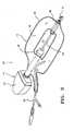
- Fig. 1shows an exemplary embodiment of a dissector/retractor 10 according to the present invention.
- the dissector/retractor 10comprises a balloon 12 (shown in Fig. 1 in an uninflated state) carried by an insertion device 14.
- the balloon 12 in an inflated stateforms an elongated torus (a surface generated by translating a substantially circular shape about an elliptical or rectangular path with curved corners) such that it has an interior open space 16.
- the balloon 12is preferably formed of two sheets of material, a top sheet 18 and a bottom sheet 20, such that in its uninflated state, the balloon 12 can be compacted into a profile of small cross-section.
- the balloonmay have other suitable shapes depending on the intended surgical application so long as it has an adjacent or interior open space held open by the inflated balloon 12.
- the cross-section of the inflated balloon 12may other than round or elliptical. It may be square, oblong, triangular, elliptical, rectangular, "C" shaped, etc.
- the balloon 12may be formed to have alternative shapes in its inflated state, e.g. circular, square, elliptical, wedge-shaped, triangular, etc.
- the balloon 12may be made of inelastic, elastic, stretchable and/or non-stretchable material.
- suitable balloon 12 materialsinclude, but are not limited to, PVC, polyethylene, polyurethane, polyamide as well as latex or silicone.
- the balloon 12is equipped with two coaxial tubular support members 26 and 28 positioned on opposite sides of the open space 16.
- the support members 26 and 28may be fixed to the balloon 12 by any suitable attachment method such as adhesive, heat sealing, press fitting, etc.
- the support members 26 and 28may be formed integrally with the balloon 12.
- the insertion device 14comprises a handle 22 at its proximal end and a guide rod 24 (also called a blunt dissector or tunneling shaft) attached to the handle 22 and extending distally from the handle 22.
- the guide rod 24is formed to have sufficient rigidity to bluntly dissect into tissue where no open space previously existed and may be made of surgical stainless steel or other suitable material.
- the guide rod 24is inserted through the support members 26 and 28.
- the guide rod 24may have a blunt tip 30 attached to its distal end or formed integrally with the guide rod 24.
- a balloon inflation harness 32extends from the balloon 12 and provides a fluid passageway into the interior of the balloon 12.
- the balloon inflation harness 32is of the same type as that described in co-pending application serial No. 08/927,371, and therefore, it will not be described in detail herein. It should be appreciated that other suitable inflation devices are possible.
- the guide rod 24may be replaced with an endoscope (not shown) which can serve as a blunt dissector.
- the guide rod 24may be a hollow tube which receives an endoscope.
- the tubemay be transparent or it may have openings through which the endoscope can view the surrounding anatomy. Using an endoscope affords the advantage of allowing visualization of the anatomy during use of the dissector/retractor 10.
- a removeable balloon cover(not shown) may be provided to surround and compact the balloon 12 in its uninflated state.
- Suitable balloon coversincluding perforated removable covers, are described in application serial No. 08/927,371 and are not described in detail herein.
- the dissector/retractors of the present inventionmay have an ergonomic handle (not shown) such as those described in application serial No. 0/927,371.
- the ergonomic handlemay further include a receptacle adapted to receive and support a standard scope and light source.
- an incisionis made in the body proximate the target tissue within the body which is to be observed and/or treated.
- the dissector/retractor 10is inserted through the incision. If a scope is utilized, the surrounding anatomy may be visualized during the procedure.
- the dissector/retractor 10is advanced by pushing on the handle 22 to bluntly tunnel the dissector/retractor 10 through body tissue. Where it is desired to create a larger tunnel or a larger dissected area, the advancement of the dissector/retractor 10 is stopped and the balloon is inflated 12 causing it to expand (if a balloon cover is utilized, the cover is removed prior to inflation).
- inflation of the balloon 12will cause dissection of the surrounding tissue.
- the balloon 12Prior to continuing the advancement of the dissector/retractor 10, the balloon 12 is deflated. Once the open space 16 of the balloon 12 is adjacent the target tissue, the balloon 12 is inflated. The inflated balloon 12 is left in place to retract the previously dissected space. Another incision is made directly above the location of the open space 16 of the balloon 12 thereby providing direct access to the area of the balloon without recourse to the tunnel just created by the dissector/retractor 10. Then, the surgeon may perform treatment on the site of interest through the direct access incision and through the open area 16 of the balloon 12.
- the balloon 12may be deflated and advanced to a new location. Then, the above step may be repeated to treat tissues in the new location. After treatment is complete, the balloon 12 is deflated and the dissector/retractor 10 is removed through the first incision.
- FIG. 3 and 4Another exemplary embodiment of a dissector/retractor 40 according to the present invention is shown in Figs. 3 and 4 .
- the dissector/retractor 40has a spoon-shaped dissector 42 attached to the distal end of the guide rod 24.
- the spoon-shaped dissector 42may be attached to the distal end of the distal support member 28.
- the dissector/retractor 40is the same as the dissector/retractor 10 described above.
- the spoon-shaped dissectoris preferably translucent but may be transparent or opaque.
- the spoon-shaped dissector 42may have a notch 44. The notch 44 is especially advantageous when dissecting along a blood vessel because the notch 44 straddles the vessel and helps prevent or reduce any undesired trauma to the vessel.
- the method of using the dissector/retractor 40is the same as that described above with respect to the dissector/retractor 10 of Fig. 1 .
- the devices and methods disclosed hereincan be used for many surgical procedures including vein harvesting and plating bones as described above. It is to be understood that the specific descriptions of the devices and methods are intended to be illustrative only and that the devices and methods may be used for tunneling, enlarging and retracting working spaces over many different structures in the body. Various arteries and veins must be exposed and mobilized for operations other than harvesting, such as for poplitiel bypass, or a dialysis vein loop, or treating abnormal communicating vasculature.
- tissuemay be dissected and treated using the devices and methods disclosed herein.
Landscapes
- Health & Medical Sciences (AREA)
- Life Sciences & Earth Sciences (AREA)
- Surgery (AREA)
- Heart & Thoracic Surgery (AREA)
- Engineering & Computer Science (AREA)
- Veterinary Medicine (AREA)
- Public Health (AREA)
- General Health & Medical Sciences (AREA)
- Animal Behavior & Ethology (AREA)
- Biomedical Technology (AREA)
- Nuclear Medicine, Radiotherapy & Molecular Imaging (AREA)
- Medical Informatics (AREA)
- Molecular Biology (AREA)
- Biophysics (AREA)
- Pathology (AREA)
- Radiology & Medical Imaging (AREA)
- Physics & Mathematics (AREA)
- Optics & Photonics (AREA)
- Anesthesiology (AREA)
- Hematology (AREA)
- Rheumatology (AREA)
- Child & Adolescent Psychology (AREA)
- Pulmonology (AREA)
- Vascular Medicine (AREA)
- Surgical Instruments (AREA)
Description
- This invention relates to devices for endoscopic vascular surgery, in particular to devices for dissecting tissue to create a working space adjacent to an elongate structure.
- Surgical endoscopy is a surgical technique of using small diameter tools such as graspers, forceps, retractors, dissectors and clamps specially designed to be inserted through small openings in the body to perform operations within the body. The surgeon performing the surgery often cannot see the operation directly, and must watch the procedure on a video monitor fed by an endoscopic camera or through an endoscope. Endoscopic surgery may be preferable to open surgery because open surgery requires large incisions, essentially opening the body cavity completely in order to perform surgery deep within the body. The terms "laparoscopic surgery," and "arthroscopic surgery," are often considered to be types of endoscopic surgery, but are commonly used synonymously to refer to endoscopic surgery and minimally invasive surgery.
- The surgeon performing such a surgery makes one, or a few, small incisions and inserts specially designed tools having small profiles through the incision and advances the tools to the desired location in the body. Long tools may be used to access over substantial distances from the incision deep into the body. Viewing the tools and the anatomy through an endoscope or on a video display from the endoscope, the surgeon can perform a wide variety of activities, including dissecting, retracting, cutting and suturing, necessary for a wide variety of surgical procedures.
- In certain types of surgery dealing with elongate structures, for example blood vessels and long bones, it is desirable to dissect and/or retract tissue away from the elongate structure along at least a portion of their length. This may be accomplished in order to facilitate introduction of a tool or implant (temporary or permanent) alongside the structure, or to harvest at least a portion of the structure, such as a length of a vessel. In some instances, it may also be desirable to provide retraction of the tissue away from the elongate structure in the dissected region to create a working and/or a visualization space. In addition it is advantageous that the retraction be accomplished in a manner which minimizes blockage of surgical access to the dissected region thereby providing ample working and/or visualization space.
- Many endoscopic surgical procedures may usefully employ such methods of dissecting and/or retracting tissue away from elongate structures. For example, in a blood vessel harvest, tissue is dissected away from the vessel and is then retracted to provide working and visualization space for ligating side branches and for completely separating the vessel from the surrounding tissue. Further, in the emergency treatment of long bone trauma, such as a fracture, it is often necessary to dissect along the bone to create space for plating. In both of these instances it is desirable to minimize the incision length, thereby accelerating the recovery process and its associated pain and reducing risk of infection. There are many inherent difficulties encountered in treating elongate structures using endoscopic techniques. For example, typically these procedures are performed through a single incision overlying one end of the region of the body to be treated. Hence, long tools must be used to reach from the incision site to the far end of the elongate structure being treated. In many situations, these long tools must navigate tortuous paths to reach the desired location in the body. These situations present several drawbacks in current methods. Firstly, it is difficult to advance long tools and to precisely position the distal end of the tools due to the extensive length of the tools and inherent visual uncertainty. Moreover, even after they are positioned, long tools are generally harder to maneuver and to operate than similar instruments having shorter lengths. Also, the long, narrow path to the desired location severely limits the maneuverability of the distal end of the instrument. This creates even greater difficulties and is especially undesirable where the orientation of the instrument is critical.
- Many types of expanding devices which can be used to dissect and/or retract tissue for use in endoscopic procedures have been disclosed. A feature common to each of these devices is a small initial (or contracted or unexpanded) profile such that it can be inserted through a small incision. Once inserted, the device can be expanded to exert force on surrounding tissue to perform dissection and/or retraction. Further, the device must be capable of being contracted after use so that it can be removed through the same small incision. The designs of known devices varies greatly. For instance, devices have been disclosed which utilize mechanical means such as expanding arms, or inflatable apparatus which expands by pressurizing with fluid, or a combination of mechanical and inflatable mechanisms. For example, in commonly assigned
U.S. Patents Nos. 5,667,520 and5,772,680 andU.S. application Serial No. 08/927,371 various apparatus comprising mechanical, inflatable and combination mechanical/inflatable devices are disclosed, which can be utilized to dissect and/or retract tissue. Depending on the nature of the application and surgical exposure desired, the apparatus are disclosed as having one or more expanding portions typically disposed on an insertion tool such as a blunt dissector or tunneling assembly, scope, rod, tube or other suitable structure. In many instances, an inflatable device provides superior performance because: (1) it can be contracted into a very small profile; (2) it is easily and variably expandable; (3) it can be readily formed into many different shapes specially designed for the particular procedure; (4) it can be made of transparent material to allow visualization through it; (5) the expansion force can be specifically and accurately directed to the desired tissue; and (6) the amount of force applied to the tissues can be precisely controlled. US 5,800,394 discloses another expanding device for creating a space. A number of forms of an expandable member of the device are disclosed including, for example, a doughnut shaped configuration. The preamble of claim 1 is based on this document.- In endoscopic procedures, an alternative to accessing the remote portions of a desired region of the body from the initial incision is to access the site from directly above the location. First, the region of interest in the body is dissected and/or retracted through an initial incision using the endoscopic techniques described above. Then, the surgeon locates the surface of the body directly above the site from the exterior of the body, such as by using the endoscope light which is often visible through the surrounding tissue. Finally, a small incision or puncture is made from directly above the site to the required depth. This method has the advantages that the surgeon is closer to the region of the body to be treated and relatively shorter instruments can be used. Furthermore, the shorter distance to the site of the procedure improves maneuverability and eases the use of the instruments. This method provides significant advantages with only a small increase in the total length of incisions.
- The method of using additional incisions directly above the previously retracted region of an endoscopic surgery, however, requires that the retractors used provide direct access to the desired site from above. Although some of the inflatable retractors/dissectors described above are suitable for retracting elongate regions and can be inserted through small incisions and provide excellent dissection and retraction, they do not provide access through the overlying tissue and around or through the retractor. Instead, these prior elongate inflatable retractors/dissectors are configured to facilitate access along the path from the initial incision and therefore have solid surfaces which block direct access to the region from positions opposite the device. Although some of the previously disclosed inflatable devices described above are suitable for retracting elongate regions, none of the devices leaves adequate surgical access to the anatomy through and around the device.
- Accordingly, there exists a need for an apparatus and corresponding method of using the apparatus which is suitable for dissecting and/or retracting elongate regions while also providing sufficient access to the region through overlying tissue and around or through the apparatus. Further, the apparatus should preferably be inflatable and adapted for use in endoscopic surgery.
- The methods and devices of the present disclosure allow surgeons to endoscopically dissect and/or retract elongate regions in the body while also providing access to the region to be treated through the overlying tissue and through or around the device. The methods and devices disclosed herein permit elongate structures, such as the saphenous vein for example, to be effectively dissected and retracted from the surrounding tissues through a small incision at one end of the structure. In addition, access to the dissected and/or retracted region is made available through the overlying tissue and through or around the dissector/retractor device.
- The invention is defined by independent claim 1.
- In an exemplary embodiment, a dissector/retractor of the present invention comprises an elongate balloon which in plan view has an interior open space through the balloon. For example, the balloon in its inflated state may be in the shape of an elongated ring or torus stretched so that it is no longer round in plan view but is instead oval or rectangular with rounded corners. The balloon may be formed of an elastic or non-elastic material. The balloon material may be transparent or substantially transparent to allow visualization or illumination through the balloon. An inflation harness is connected to the balloon and provides a fluid passageway into the interior space of the balloon.
- The balloon may have a plurality of open spaces, especially if the balloon is very long. In that case, the balloon has at least one cross member which separates the open spaces and provides structural support to maintain the open spaces (similar to the steps on a ladder).
- The balloon is carried by an insertion tool or assembly which facilitates advancing the balloon through an incision and into the body with dissection if needed to the target location. The insertion assembly preferably comprises a guide rod or blunt dissector. Alternatively, the insertion assembly may be a scope, a tube or other suitable support member. The balloon is preferably equipped with colinear tubular support members through which the insertion tool is inserted. The two support members are best positioned on opposite sides of the open space in the balloon so as to tether opposing portions of the elongate balloon. The support members may be integral parts of the balloon, or they may be separate parts which are attached to the balloon by adhesive, heat sealing, press fitting or other suitable attachment method.
- In another aspect of the invention, a spoon-shaped blunt dissector may be attached to the distal end of the insertion tool or assembly or to the distal support member. The spoon extends beyond the distal end of the insertion tool. The spoon can be used to perform blunt dissection and/or retraction to tunnel the dissector/retractor into body tissue and to create an open space for viewing or for performing surgical procedures at the distal end of the dissector/retractor.
- In another feature of the present invention, an optional balloon cover may be provided to retain the balloon with a small envelope in its uninflated state. The cover may be removeable or it may be permanently attached to the device. A resilient balloon cover may also be used which compresses the balloon upon deflation.
- In still another aspect of the present invention, the dissector may have a handle at its proximal end. The handle preferably has an ergonomic design and is designed to fit comfortably in one hand of a surgeon, and to provide the surgeon greater control of the dissector during insertion and placement. The ergonomic handle may be adapted to receive and to provide supplementary support for a scope instrument, and can also hold a light source for the scope instrument.
- In the general use of the dissector/retractor of the present invention, an incision is first made in the body at a location proximate the anatomy to be treated. The dissector/retractor is inserted through the incision with the balloon deflated, rolled and compacted. Where a scope is utilized, the entire method may be visualized. The dissector/retractor is advanced by tunneling into body tissue to where it is desired to dissect and retract body tissue to create a working space. Once the dissector/retractor is at the desired location, the balloon cover is removed from the balloon and the balloon is inflated. Upon inflation, the balloon expands. In many instances, inflation of the balloon will cause additional dissection of the surrounding tissue. If a larger dissected region is desired, multiple inflation, deflation and advancement cycles may be performed. The inflated balloon is left in place to maintain, i.e. retract, the dissected space. Then, another incision or puncture is made directly above the site of interest within the area just dissected and retracted. This incision provides direct access to the site without having to navigate along the path traveled by the dissector/retractor which may be a relatively long tunnel. The innovative configuration of the balloon has an interior open space which allows access to the desired site through the overlying tissue and through or around the balloon. Surgical instruments, diagnostic equipment and/or prosthesis may be inserted through the open space in the balloon to access the desired site of interest. Thus, a single device provides effective dissection and retraction along an elongate region of tissue thereby eliminating any need to remove a dissecting device and insert a different retracting device.
- Moreover, if it is desired to perform surgical procedures on nearby regions of tissue, the balloon may be deflated and advanced further along the desired path by blunt dissection until the next desired location is reached. Then, the balloon may be reinflated. Another lateral incision may then be made to access the next region to be treated. These steps may be repeated as necessary.
- After the treatment is complete, the balloon is deflated and the dissector/retractor is removed through the initial incision. The incisions are then closed so that they may heal.
- Still further, at any time during the procedure, the insertion tool may be removed from the balloon and original incision by pulling it proximally from the support members. Then, other surgical apparatus may be inserted through the balloon.
- A saphenous vein harvesting procedure will be described to exemplify the method of using the apparatus of the present invention for a specific procedure. The surgeon makes one small incision at each end of the saphenous vein. After making the incisions, the surgeon inserts a dissector/retractor instrument which carries an elongate balloon having an interior open space. The surgeon advances or pushes the dissector/retractor along the saphenous vein to make a small tunnel adjacent the vein. When a side branch is encountered, the surgeon advances the device until the balloon open space is adjacent the junction. The surgeon then inflates the elongate balloon to enlarge the tunnel. The surgeon then makes another incision directly above the side branch to provide direct access to the side branch through the open space in the balloon. The surgeon inserts surgical instruments through the second incision and through the overlying tissue and through the open space in the balloon to divide and ligate the side branch to free the saphenous vein. The surgeon may also utilize a laparoscopic vein harvesting device, such as one of the hooked vein harvesting devices disclosed in co-pending
U.S. application serial No. 08/444,424 entitled, "Methods and Devices for Blood Vessel Harvesting," into the After the vein is loosened and dissected free from its channel in the leg, the surgeon can cut the proximal and distal ends of the vein and easily pull the vein from the leg. These small skin incisions are then stitched so that they may heal. The small incisions heal much more readily, with fewer complications and far less pain, than the open procedures now in use. - The devices and methods of the present disclosure similarly may be effectively used in the placement of a prosthesis. The dissector/retractor is used to dissect along an elongate structure in the body similar to the method described above. The surgeon advances or pushes the dissector/retractor along the target structure until the desired location is reached. If an extended tunnel is desired, sequential inflation, deflation and advancement cycles may be performed to make a small tunnel along the bone. With the dissector/retractor at the desired location, the balloon is inflated to dissect and retract the tissue away from the target structure. The prosthesis is then put in place through the original incision. Alternatively, the insertion tool may be removed and the prosthesis can be inserted through the tubular support members. The surgeon then makes another incision directly above the side branch to provide direct access to the prosthesis. The surgeon then may adjust and/or affix the prosthesis to the target structure through the second incision and open space in the balloon. If necessary, the dissector/retractor can be deflated, advanced and reinflated to further adjust and/or affix the prosthesis through still another direct access incision. This procedure may be repeated as required.
- Accordingly, it is an object of the present disclosure to provide improved methods and devices for performing minimally invasive surgery.
- It is a further object of the present disclosure to provide an improved dissector/retractor having an elongate balloon with an open interior space and methods of using the same.
- It is yet another object of the present disclosure to provide devices and methods for performing vein harvesting procedures.
- It is still another object of the present disclosure to provide devices and methods for the placement of a prosthesis. Once the prosthesis is installed, the balloon is deflated and the dissector/retractor is removed. The procedure is completed by simply closing the small incisions.
Fig. 1 is a perspective view of an exemplary embodiment of a dissector/retractor in accordance with the present invention.Fig. 2 is a perspective view of the dissector/retractor ofFig. 1 with the balloon in an inflated state.Fig. 3 is a perspective view of another exemplary embodiment of a dissector/retractor in accordance with the present invention.Fig. 4 is a perspective view of the dissector/retractor ofFig. 3 with the balloon in an inflated state.- Referring now to the drawings,
Fig. 1 shows an exemplary embodiment of a dissector/retractor 10 according to the present invention. The dissector/retractor 10 comprises a balloon 12 (shown inFig. 1 in an uninflated state) carried by aninsertion device 14. Theballoon 12 in an inflated state (seeFig. 2 ) forms an elongated torus (a surface generated by translating a substantially circular shape about an elliptical or rectangular path with curved corners) such that it has an interioropen space 16. Theballoon 12 is preferably formed of two sheets of material, atop sheet 18 and abottom sheet 20, such that in its uninflated state, theballoon 12 can be compacted into a profile of small cross-section. It is contemplated that the balloon may have other suitable shapes depending on the intended surgical application so long as it has an adjacent or interior open space held open by theinflated balloon 12. For example, the cross-section of theinflated balloon 12 may other than round or elliptical. It may be square, oblong, triangular, elliptical, rectangular, "C" shaped, etc. Also, theballoon 12 may be formed to have alternative shapes in its inflated state, e.g. circular, square, elliptical, wedge-shaped, triangular, etc. - The
balloon 12 may be made of inelastic, elastic, stretchable and/or non-stretchable material. For example,suitable balloon 12 materials include, but are not limited to, PVC, polyethylene, polyurethane, polyamide as well as latex or silicone. - The
balloon 12 is equipped with two coaxialtubular support members open space 16. Thesupport members balloon 12 by any suitable attachment method such as adhesive, heat sealing, press fitting, etc. Alternatively, thesupport members balloon 12. - The
insertion device 14 comprises ahandle 22 at its proximal end and a guide rod 24 (also called a blunt dissector or tunneling shaft) attached to thehandle 22 and extending distally from thehandle 22. Theguide rod 24 is formed to have sufficient rigidity to bluntly dissect into tissue where no open space previously existed and may be made of surgical stainless steel or other suitable material. Theguide rod 24 is inserted through thesupport members guide rod 24 may have ablunt tip 30 attached to its distal end or formed integrally with theguide rod 24. - A
balloon inflation harness 32 extends from theballoon 12 and provides a fluid passageway into the interior of theballoon 12. Theballoon inflation harness 32 is of the same type as that described in co-pending application serial No. 08/927,371, and therefore, it will not be described in detail herein. It should be appreciated that other suitable inflation devices are possible. - In another aspect of the present disclosure, the
guide rod 24 may be replaced with an endoscope (not shown) which can serve as a blunt dissector. Alternatively, theguide rod 24 may be a hollow tube which receives an endoscope. The tube may be transparent or it may have openings through which the endoscope can view the surrounding anatomy. Using an endoscope affords the advantage of allowing visualization of the anatomy during use of the dissector/retractor 10. - In yet another feature of the present invention, a removeable balloon cover (not shown) may be provided to surround and compact the
balloon 12 in its uninflated state. Suitable balloon covers, including perforated removable covers, are described in application serial No. 08/927,371 and are not described in detail herein. Moreover, the dissector/retractors of the present invention may have an ergonomic handle (not shown) such as those described in application serial No. 0/927,371. The ergonomic handle may further include a receptacle adapted to receive and support a standard scope and light source. - In a preferred method of use, an incision is made in the body proximate the target tissue within the body which is to be observed and/or treated. With the
balloon 12 deflated, rolled and compacted around theinsertion device 14, the dissector/retractor 10 is inserted through the incision. If a scope is utilized, the surrounding anatomy may be visualized during the procedure. The dissector/retractor 10 is advanced by pushing on thehandle 22 to bluntly tunnel the dissector/retractor 10 through body tissue. Where it is desired to create a larger tunnel or a larger dissected area, the advancement of the dissector/retractor 10 is stopped and the balloon is inflated 12 causing it to expand (if a balloon cover is utilized, the cover is removed prior to inflation). In most instances, inflation of theballoon 12 will cause dissection of the surrounding tissue. Prior to continuing the advancement of the dissector/retractor 10, theballoon 12 is deflated. Once theopen space 16 of theballoon 12 is adjacent the target tissue, theballoon 12 is inflated. Theinflated balloon 12 is left in place to retract the previously dissected space. Another incision is made directly above the location of theopen space 16 of theballoon 12 thereby providing direct access to the area of the balloon without recourse to the tunnel just created by the dissector/retractor 10. Then, the surgeon may perform treatment on the site of interest through the direct access incision and through theopen area 16 of theballoon 12. - If other regions of tissue need to be treated, the
balloon 12 may be deflated and advanced to a new location. Then, the above step may be repeated to treat tissues in the new location. After treatment is complete, theballoon 12 is deflated and the dissector/retractor 10 is removed through the first incision. - Another exemplary embodiment of a dissector/
retractor 40 according to the present invention is shown inFigs. 3 and4 . The dissector/retractor 40 has a spoon-shapeddissector 42 attached to the distal end of theguide rod 24. Alternatively, the spoon-shapeddissector 42 may be attached to the distal end of thedistal support member 28. In all other respects the dissector/retractor 40 is the same as the dissector/retractor 10 described above. Hence, throughout the drawings and description, like reference numerals refer to same or similar elements and therefore some elements may not be explicitly described for all figures. The spoon-shaped dissector is preferably translucent but may be transparent or opaque. The spoon-shapeddissector 42 may have a notch 44. The notch 44 is especially advantageous when dissecting along a blood vessel because the notch 44 straddles the vessel and helps prevent or reduce any undesired trauma to the vessel. - The method of using the dissector/
retractor 40 is the same as that described above with respect to the dissector/retractor 10 ofFig. 1 . - The devices and methods disclosed herein can be used for many surgical procedures including vein harvesting and plating bones as described above. It is to be understood that the specific descriptions of the devices and methods are intended to be illustrative only and that the devices and methods may be used for tunneling, enlarging and retracting working spaces over many different structures in the body. Various arteries and veins must be exposed and mobilized for operations other than harvesting, such as for poplitiel bypass, or a dialysis vein loop, or treating abnormal communicating vasculature.
- Other structures, such as fallopian tubes, spermatic cords, bile ducts, and others may be dissected from surrounding tissue and treated similarly. These tissues may be dissected and treated using the devices and methods disclosed herein.
- While the exemplary embodiments of the devices and methods have been described, they are merely illustrative of the principles of the invention.
- Accordingly, the scope of the present invention should be determined not by the embodiments illustrated above, but by the appended claims
Claims (10)
- A surgical apparatus (10) comprising:an insertion assembly (14) having a handle (22) and a substantially rigid elongate guide rod (24) attached to said handle and extending distally from said handle;characterised by:an uninflated elongate balloon (12) carried by said insertion assembly, said uninflated balloon being rolled and compacted about said guide rod, said balloon having a deflated state and an inflated state, said balloon in its inflated state having an open space (16) extending transversely through said balloon.
- The apparatus of any preceding claim wherein said balloon in its inflated state forms an elongated torus shape.
- The apparatus of claim 1, wherein said balloon in its inflated state forms a closed shape with an interior open space (16).
- The apparatus of any preceding claim further comprising a blunt tip (30) attached to a distal end of said guide rod.
- The apparatus of claim 1, 2 or 3 further comprising a spoon-shaped dissector (42) attached to a distal end of said guide rod.
- The apparatus of claim 5 wherein said spoon-shaped dissector has a notch (44) in its distal end.
- The apparatus of any preceding claim wherein said guide rod is a tube.
- The apparatus of any preceding claim wherein said guide rod is an endoscope.
- The apparatus of any one of the preceding claims, wherein the balloon is equipped with coaxial tubular support members (26, 28) positioned on opposite sides of the open space, wherein the guide rod is inserted through the support members.
- The apparatus of any one of the preceding claims, wherein the balloon is formed of a top sheet (18) and a bottom sheet (20) of material.
Priority Applications (1)
| Application Number | Priority Date | Filing Date | Title |
|---|---|---|---|
| EP09000061.3AEP2156793B1 (en) | 1998-11-06 | 1999-11-02 | Apparatus for dissecting and retracting elongate structures |
Applications Claiming Priority (3)
| Application Number | Priority Date | Filing Date | Title |
|---|---|---|---|
| US187879 | 1994-01-27 | ||
| US09/187,879US6179854B1 (en) | 1995-05-22 | 1998-11-06 | Apparatus and method for dissecting and retracting elongate structures |
| PCT/US1999/025844WO2000027290A1 (en) | 1998-11-06 | 1999-11-02 | Apparatus and method for dissecting and retracting elongate structures |
Publications (3)
| Publication Number | Publication Date |
|---|---|
| EP1135066A1 EP1135066A1 (en) | 2001-09-26 |
| EP1135066A4 EP1135066A4 (en) | 2007-07-25 |
| EP1135066B1true EP1135066B1 (en) | 2009-01-07 |
Family
ID=22690874
Family Applications (2)
| Application Number | Title | Priority Date | Filing Date |
|---|---|---|---|
| EP09000061.3AExpired - LifetimeEP2156793B1 (en) | 1998-11-06 | 1999-11-02 | Apparatus for dissecting and retracting elongate structures |
| EP99971686AExpired - LifetimeEP1135066B1 (en) | 1998-11-06 | 1999-11-02 | Apparatus for dissecting and retracting elongate structures |
Family Applications Before (1)
| Application Number | Title | Priority Date | Filing Date |
|---|---|---|---|
| EP09000061.3AExpired - LifetimeEP2156793B1 (en) | 1998-11-06 | 1999-11-02 | Apparatus for dissecting and retracting elongate structures |
Country Status (7)
| Country | Link |
|---|---|
| US (2) | US6179854B1 (en) |
| EP (2) | EP2156793B1 (en) |
| JP (1) | JP2002529135A (en) |
| CA (1) | CA2350101C (en) |
| DE (1) | DE69940272D1 (en) |
| ES (1) | ES2318911T3 (en) |
| WO (1) | WO2000027290A1 (en) |
Families Citing this family (60)
| Publication number | Priority date | Publication date | Assignee | Title |
|---|---|---|---|---|
| US5954713A (en) | 1996-07-12 | 1999-09-21 | Newman; Fredric A. | Endarterectomy surgical instruments and procedure |
| US6860892B1 (en) | 1999-05-28 | 2005-03-01 | General Surgical Innovations, Inc. | Specially shaped balloon device for use in surgery and method of use |
| WO2002096307A2 (en)* | 2001-05-31 | 2002-12-05 | Tyco Healthcare Group Lp | Balloon cannula with over-center clamp |
| CA2450720A1 (en)* | 2001-06-13 | 2002-12-19 | Massachusetts Institute Of Technology | In vivo bioreactors |
| CA2455385C (en) | 2001-06-26 | 2011-01-25 | Tyco Healthcare Group, Lp | Conduit harvesting instrument and method |
| US20030050644A1 (en)* | 2001-09-11 | 2003-03-13 | Boucher Ryan P. | Systems and methods for accessing and treating diseased or fractured bone employing a guide wire |
| US6660016B2 (en) | 2002-03-19 | 2003-12-09 | Terumo Corporation | Integrated vein dissector and cauterizing apparatus for endoscopic harvesting of blood vessels |
| US20030225432A1 (en)* | 2002-05-31 | 2003-12-04 | Baptiste Reginald C. | Soft tissue retraction device for an endoscopic instrument |
| US7122003B2 (en)* | 2003-04-16 | 2006-10-17 | Granit Medical Innovations, Llc | Endoscopic retractor instrument and associated method |
| WO2004100799A2 (en)* | 2003-05-08 | 2004-11-25 | Tyco Healthcare Group Lp | Balloon dissector with balloon anchor cannula |
| DE602004020341D1 (en)* | 2003-06-10 | 2009-05-14 | Lumend Inc | CATHETER SYSTEM AND METHOD FOR OPENING OCCLUSIONS OF BLOOD VESSELS |
| US7556633B2 (en)* | 2004-03-01 | 2009-07-07 | Terumo Corporation | Method and apparatus for endoscopic dissection of blood vessels |
| US8721597B2 (en) | 2006-11-09 | 2014-05-13 | Ncontact Surgical, Inc. | Diaphragm entry for posterior surgical access |
| US8211011B2 (en) | 2006-11-09 | 2012-07-03 | Ncontact Surgical, Inc. | Diaphragm entry for posterior surgical access |
| US10433859B2 (en) | 2005-10-12 | 2019-10-08 | Atricure, Inc. | Diaphragm entry for posterior surgical access |
| US9808280B2 (en) | 2005-10-12 | 2017-11-07 | Atricure, Inc. | Diaphragm entry for posterior surgical access |
| JP5256206B2 (en)* | 2006-11-09 | 2013-08-07 | エヌコンタクト サージカル, インコーポレイテッド | Diaphragm entry for posterior surgical access |
| GB2467960A (en)* | 2009-02-23 | 2010-08-25 | Neosurgical Ltd | Laparoscopic surgical retraction device with expanding element and anchor arrangement |
| US11986150B2 (en) | 2009-12-15 | 2024-05-21 | Lumendi Ltd. | Method and apparatus for manipulating the side wall of a body lumen or body cavity so as to provide increased visualization of the same and/or increased access to the same, and/or for stabilizing instruments relative to the same |
| US12121209B2 (en) | 2014-02-11 | 2024-10-22 | Cornell University | Method and apparatus for providing increased visualization and manipulation of a body side wall |
| US10149601B2 (en) | 2009-12-15 | 2018-12-11 | Lumendi Ltd. | Method and apparatus for manipulating the side wall of a body lumen or body cavity so as to provide increased visualization of the same and/or increased access to the same, and/or for stabilizing instruments relative to the same |
| WO2011084490A1 (en) | 2009-12-15 | 2011-07-14 | Cornell University | Method and apparatus for stabilizing, straightening, or expanding the wall of a lumen or cavity |
| US10485401B2 (en) | 2009-12-15 | 2019-11-26 | Lumendi Ltd. | Method and apparatus for manipulating the side wall of a body lumen or body cavity so as to provide increased visualization of the same and/or increased access to the same, and/or for stabilizing instruments relative to the same |
| US9986893B2 (en) | 2009-12-15 | 2018-06-05 | Cornell University | Method and apparatus for manipulating the side wall of a body lumen or body cavity so as to provide increased visualization of the same and/or increased access to the same, and/or for stabilizing instruments relative to the same |
| US11877722B2 (en) | 2009-12-15 | 2024-01-23 | Cornell University | Method and apparatus for manipulating the side wall of a body lumen or body cavity |
| US20110172688A1 (en)* | 2010-01-11 | 2011-07-14 | Tyco Healthcare Group Lp | Conduit Harvesting Instrument and Method |
| JP5567388B2 (en)* | 2010-05-17 | 2014-08-06 | 信行 櫻澤 | Balloon-type organ pressure lifting device |
| US10646210B2 (en) | 2014-10-14 | 2020-05-12 | Covidien Lp | Methods and devices for vein harvesting |
| US10575835B2 (en) | 2014-10-14 | 2020-03-03 | Covidien Lp | Methods and devices for vein harvesting |
| US10064611B2 (en) | 2015-07-22 | 2018-09-04 | Covidien Lp | Methods and devices for vein harvesting |
| US11090101B2 (en)* | 2018-05-02 | 2021-08-17 | Medtronic Cryocath Lp | Soft balloon device and system |
| US11547466B2 (en) | 2018-06-20 | 2023-01-10 | Covidien Lp | Visualization devices and methods for use in surgical procedures |
| US11369400B2 (en) | 2019-03-20 | 2022-06-28 | Covidien Lp | Balloon dissector |
| US11484337B2 (en) | 2020-02-06 | 2022-11-01 | Covidien Lp | Surgical access device including anchor with rachet mechanism |
| US11672563B2 (en) | 2020-02-07 | 2023-06-13 | Covidien Lp | Surgical access device with rotatably actuated fixation mechanism |
| US11547441B2 (en) | 2020-02-20 | 2023-01-10 | Covidien Lp | Retention anchor for surgical access devices |
| US12268414B2 (en) | 2020-02-26 | 2025-04-08 | Covidien Lp | Retention anchor for surgical access devices |
| US11786233B2 (en) | 2020-03-27 | 2023-10-17 | Covidien Lp | Retention anchor with suture tie down for surgical access devices |
| US11432846B2 (en) | 2020-05-05 | 2022-09-06 | Covidien Lp | Surgical access device including alternating cutout fluid flow pathway for anchor inflation and deflation |
| US11376037B2 (en) | 2020-05-08 | 2022-07-05 | Covidien Lp | Surgical access device including dual lumen cannula for anchor inflation and deflation |
| US11896263B2 (en) | 2020-05-11 | 2024-02-13 | Covidien Lp | Surgical access device with fixation mechanism |
| US11439430B2 (en) | 2020-05-11 | 2022-09-13 | Covidien Lp | Surgical access device with air release mechanism |
| US11564708B2 (en) | 2020-06-15 | 2023-01-31 | Covidien Lp | Cannula assembly including an adjustable elongate shaft assembly |
| US11839404B2 (en) | 2020-07-28 | 2023-12-12 | Covidien Lp | Surgical access assembly having pre-filled air chamber |
| US11717322B2 (en) | 2020-08-17 | 2023-08-08 | Covidien Lp | Flexible cannula having selective rigidity |
| US12059176B2 (en) | 2020-10-05 | 2024-08-13 | Covidien Lp | Surgical access device with differential pressure induced fluid evacuation |
| US11844549B2 (en) | 2020-10-15 | 2023-12-19 | Covidien Lp | Surgical access device including a universal fluid flow valve |
| US11751906B2 (en) | 2020-10-29 | 2023-09-12 | Covidien Lp | Adapter for use with surgical access device for evacuation of smoke |
| US11471189B2 (en) | 2020-10-29 | 2022-10-18 | Covidien Lp | Surgical access device with fixation mechanism and illumination mechanism |
| US11583315B2 (en) | 2020-11-09 | 2023-02-21 | Covidien Lp | Surgical access device including variable length cannula |
| US12383303B2 (en) | 2020-11-10 | 2025-08-12 | Covidien Lp | Surgical access device having plural zero closure valves |
| WO2022104262A1 (en) | 2020-11-16 | 2022-05-19 | Lumendi Ltd. | Methods and apparatus for inverting a hollow sleeve and thereafter reverting an inverted hollow sleeve |
| US12137934B2 (en) | 2020-11-23 | 2024-11-12 | Covidien Lp | Surgical access device with fixation mechanism |
| US11849969B2 (en) | 2020-12-04 | 2023-12-26 | Covidien Lp | Cannula with smoke evacuation housing |
| US11944348B2 (en) | 2021-04-07 | 2024-04-02 | Covidien Lp | Surgical access device including an anchor having a suture retention mechanism |
| US11751907B2 (en) | 2021-04-13 | 2023-09-12 | Covidien Lp | Surgical access device with self-inflating balloon |
| US12121689B2 (en) | 2021-05-03 | 2024-10-22 | Covidien Lp | Surgical access device having a hollow anchor |
| US12251130B2 (en) | 2021-05-03 | 2025-03-18 | Covidien Lp | Surgical access device having a balloon and methods for manufacturing the same |
| EP4384255A4 (en)* | 2021-08-10 | 2025-04-16 | Atricure, Inc. | EXPANDABLE SPACE CREATION DEVICE AND RELATED METHODS |
| US11864761B2 (en) | 2021-09-14 | 2024-01-09 | Covidien Lp | Surgical instrument with illumination mechanism |
Family Cites Families (30)
| Publication number | Priority date | Publication date | Assignee | Title |
|---|---|---|---|---|
| US4312353A (en) | 1980-05-09 | 1982-01-26 | Mayfield Education And Research Fund | Method of creating and enlarging an opening in the brain |
| US4493711A (en) | 1982-06-25 | 1985-01-15 | Thomas J. Fogarty | Tubular extrusion catheter |
| US4779611A (en) | 1987-02-24 | 1988-10-25 | Grooters Ronald K | Disposable surgical scope guide |
| US6120437A (en)* | 1988-07-22 | 2000-09-19 | Inbae Yoon | Methods for creating spaces at obstructed sites endoscopically and methods therefor |
| US4932959A (en) | 1988-12-01 | 1990-06-12 | Advanced Cardiovascular Systems, Inc. | Vascular catheter with releasably secured guidewire |
| US5032113A (en) | 1989-04-13 | 1991-07-16 | Scimed Life Systems, Inc. | Innerless catheter |
| US5183463A (en) | 1989-02-03 | 1993-02-02 | Elie Debbas | Apparatus for locating a breast mass |
| US5345927A (en)* | 1990-03-02 | 1994-09-13 | Bonutti Peter M | Arthroscopic retractors |
| US5197971A (en) | 1990-03-02 | 1993-03-30 | Bonutti Peter M | Arthroscopic retractor and method of using the same |
| US5454365A (en) | 1990-11-05 | 1995-10-03 | Bonutti; Peter M. | Mechanically expandable arthroscopic retractors |
| US5514153A (en) | 1990-03-02 | 1996-05-07 | General Surgical Innovations, Inc. | Method of dissecting tissue layers |
| US5331975A (en) | 1990-03-02 | 1994-07-26 | Bonutti Peter M | Fluid operated retractors |
| US5359995A (en) | 1991-02-04 | 1994-11-01 | Sewell Jr Frank | Method of using an inflatable laparoscopic retractor |
| US5188630A (en) | 1991-03-25 | 1993-02-23 | Christoudias George C | Christoudias endospongestick probe |
| US5383889A (en) | 1991-05-29 | 1995-01-24 | Origin Medsystems, Inc. | Tethered everting balloon retractor for hollow bodies and method of using |
| US5361752A (en) | 1991-05-29 | 1994-11-08 | Origin Medsystems, Inc. | Retraction apparatus and methods for endoscopic surgery |
| US5307814A (en) | 1991-09-17 | 1994-05-03 | Medrad, Inc. | Externally moveable intracavity probe for MRI imaging and spectroscopy |
| US6312442B1 (en) | 1992-06-02 | 2001-11-06 | General Surgical Innovations, Inc. | Method for developing an anatomic space for laparoscopic hernia repair |
| US5269753A (en) | 1992-07-14 | 1993-12-14 | Wilk Peter J | Method for use in laparoscopic hernia repair |
| US5373840A (en) | 1992-10-02 | 1994-12-20 | Knighton; David R. | Endoscope and method for vein removal |
| US5346504A (en) | 1992-11-19 | 1994-09-13 | Ethicon, Inc. | Intraluminal manipulator with a head having articulating links |
| US5464394A (en) | 1993-06-08 | 1995-11-07 | American Biomed, Inc. | Multilumen percutaneous angioscopy catheter |
| US5391178A (en) | 1994-02-14 | 1995-02-21 | Yapor; Wesley | Cerebral dilator |
| BR9500880A (en)* | 1994-03-11 | 1995-10-17 | Essegielle Srl | Espresso machine |
| US5569183A (en)* | 1994-06-01 | 1996-10-29 | Archimedes Surgical, Inc. | Method for performing surgery around a viewing space in the interior of the body |
| US5601589A (en)* | 1994-06-29 | 1997-02-11 | General Surgical Innovations, Inc. | Extraluminal balloon dissection apparatus and method |
| US5677480A (en)* | 1995-02-24 | 1997-10-14 | L'air Liquide, Societe Anonyme Pour L'etude Et L'exploitation Des Procedes Georges Claude | Method and system for assessing the operating condition of a pressure regulator in a corrosive gas distribution system |
| US5601581A (en)* | 1995-05-19 | 1997-02-11 | General Surgical Innovations, Inc. | Methods and devices for blood vessel harvesting |
| US5667480A (en)* | 1995-10-20 | 1997-09-16 | Ethicon Endo-Surgery, Inc. | Method and devices for endoscopic vessel harvesting |
| US5902315A (en)* | 1997-08-28 | 1999-05-11 | Ethicon Endo-Surgery, Inc. | Optical tissue dissector/retractor |
- 1998
- 1998-11-06USUS09/187,879patent/US6179854B1/ennot_activeExpired - Lifetime
- 1999
- 1999-11-02JPJP2000580527Apatent/JP2002529135A/enactivePending
- 1999-11-02WOPCT/US1999/025844patent/WO2000027290A1/enactiveApplication Filing
- 1999-11-02DEDE69940272Tpatent/DE69940272D1/ennot_activeExpired - Lifetime
- 1999-11-02EPEP09000061.3Apatent/EP2156793B1/ennot_activeExpired - Lifetime
- 1999-11-02ESES99971686Tpatent/ES2318911T3/ennot_activeExpired - Lifetime
- 1999-11-02EPEP99971686Apatent/EP1135066B1/ennot_activeExpired - Lifetime
- 1999-11-02CACA002350101Apatent/CA2350101C/ennot_activeExpired - Fee Related
- 2000
- 2000-10-12USUS09/687,344patent/US6375665B1/ennot_activeExpired - Lifetime
Also Published As
| Publication number | Publication date |
|---|---|
| US6179854B1 (en) | 2001-01-30 |
| WO2000027290A1 (en) | 2000-05-18 |
| CA2350101A1 (en) | 2000-05-18 |
| EP2156793A2 (en) | 2010-02-24 |
| EP1135066A1 (en) | 2001-09-26 |
| ES2318911T3 (en) | 2009-05-01 |
| EP2156793B1 (en) | 2013-10-02 |
| EP2156793A3 (en) | 2010-03-31 |
| DE69940272D1 (en) | 2009-02-26 |
| EP1135066A4 (en) | 2007-07-25 |
| JP2002529135A (en) | 2002-09-10 |
| CA2350101C (en) | 2007-09-11 |
| US6375665B1 (en) | 2002-04-23 |
Similar Documents
| Publication | Publication Date | Title |
|---|---|---|
| EP1135066B1 (en) | Apparatus for dissecting and retracting elongate structures | |
| EP1348379B1 (en) | Balloon loaded dissecting instruments | |
| US5993472A (en) | Balloon dissecting instruments | |
| EP1011466B1 (en) | Balloon dissection instruments | |
| US7749241B2 (en) | Balloon dissecting instruments | |
| US5797947A (en) | Methods and devices for harvesting blood vessels with balloons | |
| EP0831744B1 (en) | Devices for blood vessel harvesting | |
| US5944734A (en) | Balloon dissecting instruments | |
| EP1440705B1 (en) | Balloon dissecting instruments | |
| US6596010B1 (en) | Balloon dissecting instruments | |
| EP0917480B1 (en) | Balloon dissecting instruments |
Legal Events
| Date | Code | Title | Description |
|---|---|---|---|
| PUAI | Public reference made under article 153(3) epc to a published international application that has entered the european phase | Free format text:ORIGINAL CODE: 0009012 | |
| 17P | Request for examination filed | Effective date:20010606 | |
| AK | Designated contracting states | Kind code of ref document:A1 Designated state(s):AT BE CH CY DE DK ES FI FR GB GR IE IT LI LU MC NL PT SE | |
| RBV | Designated contracting states (corrected) | Designated state(s):DE ES FR GB IE IT | |
| A4 | Supplementary search report drawn up and despatched | Effective date:20070621 | |
| 17Q | First examination report despatched | Effective date:20070823 | |
| GRAP | Despatch of communication of intention to grant a patent | Free format text:ORIGINAL CODE: EPIDOSNIGR1 | |
| RTI1 | Title (correction) | Free format text:APPARATUS FOR DISSECTING AND RETRACTING ELONGATE STRUCTURES | |
| GRAS | Grant fee paid | Free format text:ORIGINAL CODE: EPIDOSNIGR3 | |
| GRAA | (expected) grant | Free format text:ORIGINAL CODE: 0009210 | |
| AK | Designated contracting states | Kind code of ref document:B1 Designated state(s):DE ES FR GB IE IT | |
| REG | Reference to a national code | Ref country code:GB Ref legal event code:FG4D | |
| REG | Reference to a national code | Ref country code:IE Ref legal event code:FG4D | |
| REF | Corresponds to: | Ref document number:69940272 Country of ref document:DE Date of ref document:20090226 Kind code of ref document:P | |
| REG | Reference to a national code | Ref country code:ES Ref legal event code:FG2A Ref document number:2318911 Country of ref document:ES Kind code of ref document:T3 | |
| PLBE | No opposition filed within time limit | Free format text:ORIGINAL CODE: 0009261 | |
| STAA | Information on the status of an ep patent application or granted ep patent | Free format text:STATUS: NO OPPOSITION FILED WITHIN TIME LIMIT | |
| 26N | No opposition filed | Effective date:20091008 | |
| PGFP | Annual fee paid to national office [announced via postgrant information from national office to epo] | Ref country code:IT Payment date:20101124 Year of fee payment:12 | |
| PGFP | Annual fee paid to national office [announced via postgrant information from national office to epo] | Ref country code:ES Payment date:20111124 Year of fee payment:13 | |
| PG25 | Lapsed in a contracting state [announced via postgrant information from national office to epo] | Ref country code:IT Free format text:LAPSE BECAUSE OF NON-PAYMENT OF DUE FEES Effective date:20121102 | |
| REG | Reference to a national code | Ref country code:ES Ref legal event code:FD2A Effective date:20140305 | |
| PG25 | Lapsed in a contracting state [announced via postgrant information from national office to epo] | Ref country code:ES Free format text:LAPSE BECAUSE OF NON-PAYMENT OF DUE FEES Effective date:20121103 | |
| REG | Reference to a national code | Ref country code:FR Ref legal event code:PLFP Year of fee payment:17 | |
| PGFP | Annual fee paid to national office [announced via postgrant information from national office to epo] | Ref country code:DE Payment date:20151022 Year of fee payment:17 Ref country code:IE Payment date:20151023 Year of fee payment:17 Ref country code:GB Payment date:20151027 Year of fee payment:17 | |
| PGFP | Annual fee paid to national office [announced via postgrant information from national office to epo] | Ref country code:FR Payment date:20151023 Year of fee payment:17 | |
| REG | Reference to a national code | Ref country code:DE Ref legal event code:R119 Ref document number:69940272 Country of ref document:DE | |
| GBPC | Gb: european patent ceased through non-payment of renewal fee | Effective date:20161102 | |
| REG | Reference to a national code | Ref country code:IE Ref legal event code:MM4A | |
| REG | Reference to a national code | Ref country code:FR Ref legal event code:ST Effective date:20170731 | |
| PG25 | Lapsed in a contracting state [announced via postgrant information from national office to epo] | Ref country code:FR Free format text:LAPSE BECAUSE OF NON-PAYMENT OF DUE FEES Effective date:20161130 | |
| PG25 | Lapsed in a contracting state [announced via postgrant information from national office to epo] | Ref country code:GB Free format text:LAPSE BECAUSE OF NON-PAYMENT OF DUE FEES Effective date:20161102 Ref country code:IE Free format text:LAPSE BECAUSE OF NON-PAYMENT OF DUE FEES Effective date:20161102 Ref country code:DE Free format text:LAPSE BECAUSE OF NON-PAYMENT OF DUE FEES Effective date:20170601 |