EP1132041A2 - Endoscope shaft - Google Patents
Endoscope shaftDownload PDFInfo
- Publication number
- EP1132041A2 EP1132041A2EP01105299AEP01105299AEP1132041A2EP 1132041 A2EP1132041 A2EP 1132041A2EP 01105299 AEP01105299 AEP 01105299AEP 01105299 AEP01105299 AEP 01105299AEP 1132041 A2EP1132041 A2EP 1132041A2
- Authority
- EP
- European Patent Office
- Prior art keywords
- endoscope shaft
- shaft according
- channels
- endoscope
- bellows
- Prior art date
- Legal status (The legal status is an assumption and is not a legal conclusion. Google has not performed a legal analysis and makes no representation as to the accuracy of the status listed.)
- Granted
Links
- 239000000463materialSubstances0.000claimsabstractdescription8
- 239000003000extruded plasticSubstances0.000claimsabstractdescription6
- 229920001296polysiloxanePolymers0.000claimsdescription10
- 239000012530fluidSubstances0.000claimsdescription9
- 210000005225erectile tissueAnatomy0.000claimsdescription5
- 230000008878couplingEffects0.000claimsdescription3
- 238000010168coupling processMethods0.000claimsdescription3
- 238000005859coupling reactionMethods0.000claimsdescription3
- XUIMIQQOPSSXEZ-UHFFFAOYSA-NSiliconChemical compound[Si]XUIMIQQOPSSXEZ-UHFFFAOYSA-N0.000abstract2
- 229910052710siliconInorganic materials0.000abstract2
- 239000010703siliconSubstances0.000abstract2
- 238000010276constructionMethods0.000description6
- 238000010586diagramMethods0.000description4
- 230000001954sterilising effectEffects0.000description4
- 238000004659sterilization and disinfectionMethods0.000description4
- 238000013461designMethods0.000description3
- 238000000034methodMethods0.000description3
- 239000004033plasticSubstances0.000description3
- 238000005452bendingMethods0.000description2
- 238000003780insertionMethods0.000description2
- 230000037431insertionEffects0.000description2
- 230000000968intestinal effectEffects0.000description2
- 210000000936intestineAnatomy0.000description2
- 238000004519manufacturing processMethods0.000description2
- 210000002784stomachAnatomy0.000description2
- 210000000436anusAnatomy0.000description1
- 238000001574biopsyMethods0.000description1
- 230000015572biosynthetic processEffects0.000description1
- 238000004891communicationMethods0.000description1
- 238000001514detection methodMethods0.000description1
- 210000001198duodenumAnatomy0.000description1
- 210000003238esophagusAnatomy0.000description1
- 238000001125extrusionMethods0.000description1
- 238000011010flushing procedureMethods0.000description1
- 239000007788liquidSubstances0.000description1
- 238000007789sealingMethods0.000description1
- 210000005070sphincterAnatomy0.000description1
- 230000008961swellingEffects0.000description1
- 230000001360synchronised effectEffects0.000description1
- 210000001519tissueAnatomy0.000description1
- 238000012549trainingMethods0.000description1
- 210000000626ureterAnatomy0.000description1
- 210000003708urethraAnatomy0.000description1
- 210000003932urinary bladderAnatomy0.000description1
- 230000000007visual effectEffects0.000description1
Images

Classifications
- A—HUMAN NECESSITIES
- A61—MEDICAL OR VETERINARY SCIENCE; HYGIENE
- A61B—DIAGNOSIS; SURGERY; IDENTIFICATION
- A61B1/00—Instruments for performing medical examinations of the interior of cavities or tubes of the body by visual or photographical inspection, e.g. endoscopes; Illuminating arrangements therefor
- A61B1/012—Instruments for performing medical examinations of the interior of cavities or tubes of the body by visual or photographical inspection, e.g. endoscopes; Illuminating arrangements therefor characterised by internal passages or accessories therefor
- A61B1/018—Instruments for performing medical examinations of the interior of cavities or tubes of the body by visual or photographical inspection, e.g. endoscopes; Illuminating arrangements therefor characterised by internal passages or accessories therefor for receiving instruments
- A—HUMAN NECESSITIES
- A61—MEDICAL OR VETERINARY SCIENCE; HYGIENE
- A61B—DIAGNOSIS; SURGERY; IDENTIFICATION
- A61B1/00—Instruments for performing medical examinations of the interior of cavities or tubes of the body by visual or photographical inspection, e.g. endoscopes; Illuminating arrangements therefor
- A61B1/005—Flexible endoscopes
Definitions
- the present inventionrelates to an endoscope shaft according to the preamble of claim 1.
- Endoscopesare devices, especially for the exploration of Cavities or tubular channels of the body for example for medical purposes. Such endoscopes are preferably used for exploration of the esophagus Stomach, the duodenum from the stomach, the intestine from the anus from the urethra, bladder and ureter. Usually, endoscopes have a front end Lighting device and with optics for visual Detection of the area in front of the body cavity or Body channel equipped.
- Endoscopesalso usually have a so-called working channel through which various working instruments are introduced and can be operated, e.g. Pliers for removing Tissue samples, biopsy needles, heated cutting wires, smaller ones Scissors or the like.
- Pliersfor removing Tissue samples, biopsy needles, heated cutting wires, smaller ones Scissors or the like.
- Function channelsfor example a fluid channel for Flushing liquid and control wires for angling the Endoscope front end present in several directions. All in all has the endoscope apart from its rear operating end and a connecting strand, an elongated, flexible rod-shaped Shape.
- Usual outside diametersare about Range from 9 to 15 mm, slightly larger on the front head.
- the object of the inventionis in creating an endoscope shaft that is essential is cheaper to produce, and at which the risk damage, for example in the context of Sterilization processes is eliminated.
- This inventionis characterized by an endoscope shaft with features of claim 1 solved.
- the inventionis based on the following consideration:
- an endoscope of this typeis known.
- This endoscopeconsists essentially of an endoscope head, or distal End to which an endoscope shaft from like in the beginning described flexible but flexible shear stiffness Connects tubular body and an operating device on lower end of the endoscope shaft.
- the control devicehas a number of rotatably mounted on the endoscope shaft Actuating wheels, which over service wires or building trains, which is slidable within the endoscope shaft are operatively connected to the distal end.
- the double hose system known from this publicationprovides for the endoscope shaft to be placed on both sides Sliding hose, which in turn through a Drive device is movable, on which this forming inner tube section of the everting tube acts.
- the drive devicehas at least one continuously driving feed means, for example a Number of drive wheels, which radially on the inner Hose section can be pressed to this in the axial direction of the To move the shaft essentially continuously.
- the contact pressure of the Feed means selected on the inner tube sectionis that the shaft at least in the area of the feed means is in direct frictional contact with the inner tube section.
- the feed meansis one or more friction wheels formed, as already indicated above, against the inner tube section with a predetermined or adjustable contact pressure are preloaded, so that on the one hand one continuous and the other one possible slip-free advance of the endoscope shaft into the cavity a patient is guaranteed.
- the drive devicehas a device for Synchronization of the shaft movement with the Slip hose movement.
- Thiscan be an axially fixed on the shaft rear and front end or clamping piece on which slidable depending on the feed direction of the rear or front Foldable area of the everting tube is tight, so that the One-piece hose over the rear or front end piece Braking force against the currently prevailing feed force onto the shaft.
- the Synchronizer on the rear end section of the shaft acting roller or spindle drivethe is synchronized with the slip hose drive in such a way that the feed speed of the shaft is half the Feed speed of the inner tube section is.
- the endoscope shaftwhich consists of a Hose body, a central working channel and one Number of function channels, exists with one To provide silicone cover that marked above Surrounds the hose body on the outside and thus the outer layer of the endoscope shaft.
- the core of the endoscope shaft performing tube bodyitself consists of a extruded plastic material.
- the silicone coveracts like a soft pillow, which against the hose body in the event of an impact Protects damage. It has also been shown that the silicone case despite its highly elastic, soft Property as an abutment for a from the prior art known drive device, for example the above described slip hose drive system is suitable.
- Figure 1shows a schematic diagram of a distal End portion of an endoscope shaft according to a preferred Embodiment of the invention in cross section.
- Figure 2shows the distal end portion in plan view as Schematic diagram
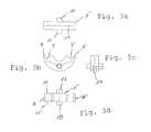
- 3a to 3dshow the structure of a cavernous body
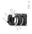
- Figure 4shows the sequence of a plurality of Cavernous bodies in perspective view with formation of the distal end according to the preferred embodiment
- Fig. 5shows the top view of an endoscope shaft according to the preferred embodiment of the invention.
- the movable distal end portionis one Endoscope shaft according to the preferred embodiment of the Invention shown as a schematic diagram.
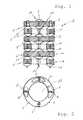
- each layer of eachis constructed of two diametrically opposed bodies.
- FIG 2is the top view of the movable distal End section 1 shown as a schematic diagram. Every body 2, 3, 4 therefore consists of a semicircular, disc-like ring element 5 seen in the circumferential direction swelling body 6 forms in its central section. To the two respective end sides of the semicircular ring disk 5 are extending in the thickness direction of the disc 5 Notches 7, 7 'are preferably semicircular. The semicircular washers 5 are in each layer their two end faces 8, 8 'put together so that the notches 7, 7 lying opposite one another; 7 ', 7' the respective end sides two diametrically define opposite through openings 9, 9 '.
- the Body pairs that are directly in the longitudinal direction of the distal End sectionare adjacent, an additional 90 ° to each other out of phase.
- the Cavernous body 6 with respect to the one layer on three and nine O'clock and on the adjacent shift to zero and six Clockis on.
- the erectile tissue 6are according to the present Execution example designed as an expandable bellows, which can be operated pneumatically or hydraulically. Alternatively it is of course also possible as the erectile tissue 6 to form piezoelectric elements.
- the erectile tissue 6, in the present case forming the expandable bellowsa swivel mechanism of the movable distal In the end. All bellows are the same for this Angular position, i.e. the bellows at zero o'clock position, at three o'clock position, at six o'clock and nine o'clock coupled with each other.
- This couplingconsists of one Line piece 10, which two longitudinally spaced bellows same angular position both mechanically and hydraulically or pneumatically connects with each other, this Line pieces 10 through the through openings 9, 9'des body pairs between each runs.
- Through the Line sections 10is accordingly a hydraulic or pneumatic fluid connection as well as a mechanical coupling for preventing the individual from falling apart Layers created.
- the bellowsare in principle in accordance with FIG opposite flat sides of the semicircular Ring discs 5 and are through holes 11, which extend through the washers 5, with each other fluid-connected.
- Annular washers 5have a central through opening 12 per layer formed, which extends along the entire movable distal End section 1 extends and a working channel for the Introducing surgical instruments, auxiliary instruments or forms optics.
- This hydraulic Pipe systemwhich is not in the present figures shown consists essentially of four channels through the also not shown endoscope shaft in it trained working channels and led to a central Hydraulic pressure source are connected.
- Hydraulic pressure sourceis preferably a manually operated pressure pump consisting of four individual pumps can be operated independently of one another or in a coupled manner, such that that when pressure is applied to the bellows an angular position of the Pressure in the bellows at the opposite angular position is relaxed.
- connecting pieces 17, 18are formed, which are aligned with each other and in the Cavity of the ring body 5 open.
- the connecting pieces 17, 18can be integrally formed with the washer 5 or be welded to it.
- Ring body 5made up of two shell halves running along the radial outer and radially inner side in the circumferential direction with each other are welded.
- distal end section 1can be rubber or rubber laminate as a material for the distal end section 1 .
- the distal End sectionis on the end face of the Enoscopic shaft welded in such a way that the free Connection piece 13 in the two lowest layers with the Hydraulic channels in fluid communication along the hydraulic shaft come.
- the endoscope shafthas one Tube body 20 from an estruded Extruded plastic profile with a central working channel 21 large diameter.
- the working channel 21has how A continuous one has already been indicated above Connection to the central through opening 12 of the distal End section 1.
- a number of Function channels 22with a smaller cross section in the Hose body 20 formed radially from the central Working channel 21 spaced and at the same angular distance are arranged to each other.
- Function channels 22provided in the hose body 20, which as Pressure channels for actuating the distal end section 1 with the Connection pieces are in fluid connection.
- Theis at the rear end section of the endoscope shaft Pressure medium source, which is also connected to the pressure channels used functional channels is connected and preferably forms a unit with the endoscope shaft.
- a silicone sleeve 24is around the hose body 20 arranged in the form of a jacket, which the hose body 20 in surrounds substantially over its entire length and preferably at the distal end section 1 in the area thereof Attachment point on the endoscope shaft ends or on the front the distal end section 1 is welded in a sealing manner.
- the grooves 23are preferably located exactly between the functional channels 22 of the hose body 20.
- the grooves 23are radially sealed by the silicone sleeve covered and thus form external functional channels in which Cable, for example, for connecting a camera chip or a Lighting device are laid on the distal end section.
- the endoscope shaftas a disposable item to design. Therefore, in order to reduce manufacturing costs the distal end section made of plastic simply opens the end face of the endoscope shaft is welded on, whereby the connecting piece 17, 18 with the pressure channels 22 of the Hose body are fluidly connected.
- the Endoscope shaft constructionnot only in combination with the distal end section according to the invention but also with other, already known shaft ends can be combined.
- the actuatoris not on the one described Hand pump limited as a disposable item but could also be a conventional reusable pressure source to which the Endoscope shaft is easy to connect. In the latter case at the rear end of the shaft connection points for the connection of connecting lines between the pressure source and Function channels formed.
- the inventionrelates to an endoscope shaft consisting of a Hose body that has a central working channel and one Number of function channels.
- the hose bodyis according to the invention from an extruded plastic material manufactured, which is surrounded by a silicone shell, which the Forms outer layer of the endoscope shaft.
Landscapes
- Health & Medical Sciences (AREA)
- Life Sciences & Earth Sciences (AREA)
- Surgery (AREA)
- Nuclear Medicine, Radiotherapy & Molecular Imaging (AREA)
- Biomedical Technology (AREA)
- Optics & Photonics (AREA)
- Pathology (AREA)
- Radiology & Medical Imaging (AREA)
- Biophysics (AREA)
- Engineering & Computer Science (AREA)
- Physics & Mathematics (AREA)
- Heart & Thoracic Surgery (AREA)
- Medical Informatics (AREA)
- Molecular Biology (AREA)
- Animal Behavior & Ethology (AREA)
- General Health & Medical Sciences (AREA)
- Public Health (AREA)
- Veterinary Medicine (AREA)
- Endoscopes (AREA)
Abstract
Description
Translated fromGermanDie vorliegende Erfindung betrifft einen Endoskopschaft gemäßdem Oberbegriff des Patentanspruchs 1.The present invention relates to an endoscope shaft according tothe preamble of
Endoskope sind Geräte, insbesondere zur Exploration vonHohlräumen oder röhrenartigen Kanälen des Körpersbeispielsweise für medizinische Zwecke. Derartige Endoskopewerden vorzugsweise zur Exploration der Speiseröhre, desMagens, des Zwölffingerdarms vom Magen aus, des Darms vom Anusaus, der Harnröhre, der Blase und der Harnleiter verwendet.Zumeist sind Endoskope an ihrem Vorderende mit einerBeleuchtungseinrichtung und mit einer Optik zur visuellenErfassung des davor liegenden Bereichs des Körperhohlraums oderKörperkanals ausgerüstet.Endoscopes are devices, especially for the exploration ofCavities or tubular channels of the bodyfor example for medical purposes. Such endoscopesare preferably used for exploration of the esophagusStomach, the duodenum from the stomach, the intestine from the anusfrom the urethra, bladder and ureter.Mostly, endoscopes have a front endLighting device and with optics for visualDetection of the area in front of the body cavity orBody channel equipped.
Endoskope weisen ferner in der Regel einen sog. Arbeitskanalauf, durch den diverse Arbeitsinstrumente eingeführt undbedient werden können, z.B. Zangen zur Entnahme vonGewebeproben, Biopsienadeln, beheizbare Schneiddrähte, kleinereScheren oder dergleichen. Schließlich sind in der RegelFunktionskanäle beispielsweise ein Fluidkanal fürSpülflüssigkeit und Bedienungsdrähte zum Abwinkeln desEndoskopvorderendes in mehrere Richtungen vorhanden. Insgesamthat das Endoskop, abgesehen von seinem hinteren Bedienungsendeund einem Anschlußstrang, eine langgestreckte, biegsamstabförmigeGestalt. Übliche Außendurchmesser liegen etwa imBereich von 9 bis 15 mm, am vorderen Kopf etwas größer.Endoscopes also usually have a so-called working channelthrough which various working instruments are introduced andcan be operated, e.g. Pliers for removingTissue samples, biopsy needles, heated cutting wires, smaller onesScissors or the like. After all, usuallyFunction channels for example a fluid channel forFlushing liquid and control wires for angling theEndoscope front end present in several directions. All in allhas the endoscope apart from its rear operating endand a connecting strand, an elongated, flexible rod-shapedShape. Usual outside diameters are aboutRange from 9 to 15 mm, slightly larger on the front head.
Bisher werden Endoskope dadurch in den Körper eingeführt, dassder Arzt von dem aus dem Körper herausragenden Teil desEndoskops her das drucksteife Endoskop bzw. den drucksteifenEndoskopschaft in den Körper hinein schiebt. Diese Art des Einführens des Endoskops ist besonders mühsam, schwierig undzeitraubend insbesondere beim Koloskop, da im letzteren Fallder Darm Abbiegungen und häufig Engstellen aufweist. Demzufolgegehören koloskopische Untersuchungen bisher zu den aufwendigenund für den Patienten unangenehmen Untersuchungen und kommendeshalb für eine breite Anwendung kaum in Betracht. Das Umgehenmit einem Koloskop erfordert zudem einen hiermit erfahrenenArzt.So far, endoscopes have been introduced into the body in thatthe doctor of the part of the body protruding from the bodyEndoscope the pressure-resistant endoscope or the pressure-resistantPushes the endoscope shaft into the body. This kind ofInserting the endoscope is particularly troublesome, difficult, andtime-consuming especially with the colonoscope, since in the latter casethe bowel has bends and often narrow points. As a resultColonoscopic examinations have so far been elaborateand unpleasant examinations for the patient and cometherefore hardly considered for wide application. Bypassingwith a colonoscope also requires an experienced herebyDoctor.
Des weiteren hat sich aus dem Stand der Technik gezeigt, dassEndoskope der bekannten Bauart aufgrund der von ihnengeforderten Steifigkeit für ein Einschieben in'den zuuntersuchenden Patientenhohlraum, bei gleichzeitigerBiegefähigkeit äußerst aufwendige und damit kostenintensiveKonstruktionen darstellen. Diese Konstruktionen sind derartteuer, dass sie immer wieder verwendet müssen. Es ist dahernotwendig, nach jeder Untersuchung aufwendigeSterilisationsmaßnahmen durchzuführen, wobei letztlich aucheine Gefahr einer Beschädigung des Endoskopschafts besteht,insbesondere dann, wenn ungeschultes Personal derartigeSterilisationsvorgänge durchführt.Furthermore, it has been shown from the prior art thatEndoscopes of the well-known type due to the of themstiffness required for insertion into theexamining patient cavity, with simultaneousFlexibility extremely complex and therefore costlyRepresent constructions. These constructions are like thisexpensive that they have to be used again and again. It is thereforenecessary, elaborate after each examinationTo carry out sterilization measures, ultimately alsothere is a risk of damage to the endoscope shaft,especially when untrained personnel doPerforms sterilization processes.
Angesichts dieser Situation besteht die Aufgabe der Erfindungdarin, einen Endoskopschaft zu schaffen, der wesentlichkostengünstiger herstellbar ist, und bei welchem die Gefahreines Beschädigens beispielsweise im Rahmen vonSterilisationsvorgängen beseitigt ist.In view of this situation, the object of the invention isin creating an endoscope shaft that is essentialis cheaper to produce, and at which the riskdamage, for example in the context ofSterilization processes is eliminated.
Diese Erfindung wird durch einen Endoskopschaft mit Merkmalendes Anspruchs 1 gelöst.This invention is characterized by an endoscope shaft with featuresof
Die Erfindung geht dabei von der folgenden Überlegung aus:The invention is based on the following consideration:
Aus dem Stand der Technik, insbesondere gemäß der DE 42 42 291A1 ist ein Endoskop dieser Gattung bekannt. Dieses Endoskopbesteht im wesentlichen aus einem Endoskopkopf, oder distalenEnde, an das sich ein Endoskopschaft aus einem wie eingangs beschriebenen flexiblen biegsamen jedoch schubsteifenRohrkörper anschließt und einer Bedienungseinrichtung amunteren Ende des Endoskopschafts. Die Bedienungseinrichtung hateine Anzahl von drehbar am Endoskopschaft gelagertenBetätigungsrädern, die über Bedienungsdrähte oder Bautenzüge,welche innerhalb des Endoskopschafts verschieblich verlegtsind, mit dem distalen Ende wirkverbunden sind.From the prior art, in particular according to DE 42 42 291A1 an endoscope of this type is known. This endoscopeconsists essentially of an endoscope head, or distalEnd to which an endoscope shaft from like in the beginningdescribed flexible but flexible shear stiffnessConnects tubular body and an operating device onlower end of the endoscope shaft. The control device hasa number of rotatably mounted on the endoscope shaftActuating wheels, which over service wires or building trains,which is slidable within the endoscope shaftare operatively connected to the distal end.
Für ein Einführen dieses Endoskopschafts beispielsweise in denDarm eines zu behandelnden Patienten verwendet dieser Stand derTechnik eine Art Doppelstülpschlauch-System, wie es nachfolgendkurz beschrieben wird:For insertion of this endoscope shaft, for example in theThis state of the intestine of a patient to be treated usesTechnique a kind of double hose system, as followsis briefly described:
Das aus dieser Druckschrift bekannte Doppelstülpschlauchsystemsieht vor, den Endoskopschaft in einem beidseitig gestülptenSchlauch gleitend zu führen, der wiederum durch eineAntriebseinrichtung fortbewegbar ist, des auf den hierbei sichausbildenden inneren Schlauchabschnitt des Stülpschlauchseinwirkt. Die Antriebseinrichtung hat zumindest einkontinuierlich antreibendes Vorschubmittel, beispielsweise eineAnzahl von Antriebsrädern, welches radial auf den innerenSchlauchabschnitt pressbar ist, um diesen in Axialrichtung desSchafts im wesentlichen kontinuierlich zu bewegen. Dies hat denVorteil, dass der kontinuierliche Vortrieb desStülpschlauchsystems exakt steuerbar und damit beispielsweisedas distale Ende des Endoskops ortsgenau führbar ist.The double hose system known from this publicationprovides for the endoscope shaft to be placed on both sidesSliding hose, which in turn through aDrive device is movable, on which thisforming inner tube section of the everting tubeacts. The drive device has at least onecontinuously driving feed means, for example aNumber of drive wheels, which radially on the innerHose section can be pressed to this in the axial direction of theTo move the shaft essentially continuously. This has theAdvantage that the continuous propulsion of theInvertable hose system precisely controllable and thus for examplethe distal end of the endoscope can be guided precisely.
Hierbei ist es vorgesehen, dass die Anpresskraft desVorschubmittels auf den inneren Schlauchabschnitt so gewähltist, dass der Schaft zumindest im Bereich des Vorschubmittelsim direkten Reibkontakt mit dem inneren Schlauchabschnitt ist.Das Vorschubmittel wird von einem oder mehreren Reibräderngebildet, wie vorstehend bereits angedeutet wurde, die gegenden inneren Schlauchabschnitt mit einer vorbestimmten odereinstellbaren Anpresskraft vorspannbar sind, so dass zum einenein kontinuierlicher und zum anderen ein möglichstschlupffreier Vorschub des Endoskopschafts in den Hohlraum eines Patienten gewährleistet wird. Dabei bildet derEndoskopschaft selbst das Widerlager der Reibräder.It is provided that the contact pressure of theFeed means selected on the inner tube sectionis that the shaft at least in the area of the feed meansis in direct frictional contact with the inner tube section.The feed means is one or more friction wheelsformed, as already indicated above, againstthe inner tube section with a predetermined oradjustable contact pressure are preloaded, so that on the one handone continuous and the other one possibleslip-free advance of the endoscope shaft into the cavitya patient is guaranteed. The formsEndoscope shaft itself the abutment of the friction wheels.
Des weiteren hat die Antriebseinrichtung eine Vorrichtung zurSynchronisation der Schaftbewegung mit derStülpschlauchbewegung. Diese kann ein am Schaft axial fixierteshinteres und vorderes End- oder Klemmstück sein, an demgleitfähig je nach Vorschubrichtung der hintere oder vordereStülpbereich des Stülpschlauchs fest anliegt, so dass derStülpschlauch über das hintere oder vordere Endstück eineBremskraft entgegen der gerade vorherrschenden Vorschubkraftauf den Schaft aufbringt. Alternativ hierzu kann dieSynchronisationsvorrichtung ein auf den hinteren Endabschnittdes Schafts einwirkender Rollen- oder Spindelantrieb sein, dermit dem Stülpschlauchantrieb derart synchronisiert ist, dassdie Vorschubgeschwindigkeit des Schafts die Hälfte derVorschubgeschwindigkeit des inneren Schlauchabschnitts beträgt.Furthermore, the drive device has a device forSynchronization of the shaft movement with theSlip hose movement. This can be an axially fixed on the shaftrear and front end or clamping piece on whichslidable depending on the feed direction of the rear or frontFoldable area of the everting tube is tight, so that theOne-piece hose over the rear or front end pieceBraking force against the currently prevailing feed forceonto the shaft. Alternatively, theSynchronizer on the rear end sectionof the shaft acting roller or spindle drive, theis synchronized with the slip hose drive in such a way thatthe feed speed of the shaft is half theFeed speed of the inner tube section is.
Der wesentliche Vorteil der aus der DE 42 42 291 A1 bekanntenEndoskopievorrichtung besteht darin, dass der Enoskopschaftüber dessen Gesamtlänge mit Ausnahme des vorderen, beweglichendistalen Endabschnitts von der Antriebseinrichtung, nämlich demDoppelstülpschlauchsystem ummantelt ist, und damit nicht mitder Hohlraumwandung unmittelbar in Kontakt kommt. Darüberhinaus schafft das Doppelstülpschlauchsystem eine ArtSelbstantrieb, wodurch keine Vorschubkräfte auf denEndoskopschaft von dessen Bedienungsende aus mehr aufgebrachtwerden müssen.The main advantage of those known from DE 42 42 291 A1Endoscopic device is that of the enoscopic shaftover its entire length with the exception of the front, movabledistal end portion of the drive device, namely theDouble hose system is covered, and therefore not withthe cavity wall comes into direct contact. About thatIn addition, the double hose system creates a kindSelf-propelled, which means no feed forces on theEndoscope shaft from its operating end more appliedNeed to become.
Die DE 42 42 291 A1 sowie die darin angegebene technische Lehreschafft somit die Voraussetzung zur Ausbildung neuartigerEndoskopschäfte, wie sie nunmehr Gegenstand dieser Erfindungsind.DE 42 42 291 A1 and the technical teaching specified thereinthus creates the prerequisite for training new typesEndoscope shafts as are now the subject of this inventionare.
Der Kern der Erfindung gemäß dem Patentanspruch 1 liegtdemzufolge darin, den Endoskopschaft, welcher aus einemSchlauchkörper, der einen zentralen Arbeitskanal sowie eine Anzahl von Funktionskanälen ausbildet, besteht, mit einerSilikonhülle zu versehen, die den vorstehend gekennzeichnetenSchlauchkörper außenseitig umgibt und damit die Außenschichtdes Endoskopschafts bildet. Der den Kern des Endoskopschaftsdarstellende Schlauchkörper selbst besteht aus einemextrudierten Kunststoffmaterial.The essence of the invention according to
Es hat sich gezeigt, dass dieser Aufbau besonders kostengünstigherstellbar ist, da keine Rücksicht auf Biegesteifigkeiten inLängsrichtung des Schafts genommen werden muss, wenn einsolcher Schaft beispielsweise mit einer Antriebseinrichtung inForm eines Doppelstülpschlauchssystem bekannter Bauarteingesetzt wird. Extrudierte Kunststoffstrangprofile sindäußerst kostengünstig, wobei die Silikonhülle auf einfacheWeise um den extrudierten Schlauchkörper gegossen werden kann.It has been shown that this structure is particularly cost-effectivecan be produced since there is no consideration for bending stiffness inLongitudinal direction of the shaft must be taken when asuch a shaft, for example with a drive device inForm of a double hose system of known designis used. Extruded plastic extrusions areextremely inexpensive, the silicone case on simpleWay can be cast around the extruded tube body.
Dieser Aufbau ist derart kostengünstig zu fertigen, dass dererfindungsgemäße Endoskopschaft als Einwegartikel verwendetwerden kann, bei dem Sterilisationsmaßnahmen überflüssig sind.This structure is so inexpensive to manufacture that theEndoscope shaft according to the invention used as a disposable itemthat sterilization measures are superfluous.
Darüber hinaus wirkt die Silikonhülle wie ein weiches Kissen,welches den Schlauchkörper bei einem Aufprall gegenBeschädigung schützt. Es hat sich dabei ferner gezeigt, dassdie Silikonhülle trotz ihrer hoch elastischen, weichenEigenschaft als Widerlager für eine aus dem Stand der Technikbekannte Antriebseinrichtung, beispielsweise das vorstehendbeschriebene Stülpschlauchantriebssystms geeignet ist.In addition, the silicone cover acts like a soft pillow,which against the hose body in the event of an impactProtects damage. It has also been shown thatthe silicone case despite its highly elastic, softProperty as an abutment for a from the prior artknown drive device, for example the abovedescribed slip hose drive system is suitable.
Weitere vorteilhafte Ausgestaltungen der Erfindung sind dabeiGegenstand der übrigen Unteransprüche.Further advantageous embodiments of the invention are includedSubject of the other subclaims.
Die Erfindung wird nachstehend anhand eines bevorzugtenAusführungsbeispiels unter Bezugnahme auf die begleitendenZeichnungen näher erläutert.The invention is described below with reference to a preferred oneEmbodiment with reference to the accompanyingDrawings explained in more detail.
Figur 1 zeigt eine Prinzipdarstellung eines distalenEndabschnitts eines Endoskopschafts gemäß einem bevorzugtenAusführungsbeispiel der Erfindung in Querschnittsdarstellung.Figure 1 shows a schematic diagram of a distalEnd portion of an endoscope shaft according to a preferredEmbodiment of the invention in cross section.
Figur 2 zeigt den distalen Endabschnitt in Draufsicht alsPrinzipdarstellung,Figure 2 shows the distal end portion in plan view asSchematic diagram,
Figur 3a bis 3d zeigen den Aufbau eines Schwellkörpers,3a to 3d show the structure of a cavernous body,
Figur 4 zeigt die Aneinanderreihung einer Mehrzahl vonSchwellkörpern in Perspektivenansicht unter Ausbildung desdistalen Endes gemäß dem bevorzugten Ausführungsbeispiel undFigure 4 shows the sequence of a plurality ofCavernous bodies in perspective view with formation of thedistal end according to the preferred embodiment and
Fig. 5 zeigt die Draufsicht eines Endoskopschafts gemäß dembevorzugten Ausführungsbeispiel der Erfindung.Fig. 5 shows the top view of an endoscope shaft according to thepreferred embodiment of the invention.
In Figur 1 ist der bewegliche distale Endabschnitt einesEndoskopschafts gemäß dem bevorzugten Ausführungsbeispiel derErfindung als Prinzipskizze dargestellt.In Figure 1, the movable distal end portion is oneEndoscope shaft according to the preferred embodiment of theInvention shown as a schematic diagram.
Wie aus der Figur 1 zu entnehmen ist, besteht der beweglichedistale Endabschnitt 1 des erfindungsgemäßen Endoskopschaftsaus einer Mehrzahl von längs neben- bzw. übereinandergeschichteter Körper 2, 3, 4, wobei jede Schicht aus jeweilszwei diametrisch zueinander liegender Körpern aufgebaut ist.As can be seen from Figure 1, there is the movable
In Figur 2 ist die Draufsicht des beweglichen distalenEndabschnitts 1 als Prinzipdarstellung abgebildet. Jeder Körper2, 3, 4 besteht demzufolge aus einem halbkreisförmigen,scheibenartigen Ringelement 5, das in Umfangsrichtung gesehenin seinem Mittenabschnitt Schwellkörper 6 ausbildet. An denzwei jeweiligen Endseiten der halbkreisförmigen Ringscheibe 5sind in Dickenrichtung der Scheibe 5 sich erstreckendeEinkerbungen7, 7' vorzugsweise halbkreisförmig ausgebildet. Diehalbkreisförmigen Ringscheiben 5 sind dabei in jeder Schicht anihren beiden Endseiten 8, 8' aneinander gelegt, derart, dassdie hierbei sich gegenüberliegenden Einkerbungen 7,7; 7', 7' an den jeweiligen Endseiten zwei diametrisch sichgegenüberliegende Durchgangsöffnungen 9, 9' definieren.In Figure 2 is the top view of the movable
Wie ferner aus der Figur 1 zu entnehmen ist, sind dieKörperpaare, welche unmittelbar in Längsrichtung des distalenEndabschnitts benachbart liegen, zusätzlich 90° zueinanderphasenverschoben. Hierdurch ordnen sich jeweils abwechselnd dieSchwellkörper 6 bezüglich der einen Schicht auf drei und neunUhr und auf der jeweils benachbarten Schicht auf null und sechsUhr an.As can also be seen from FIG. 1, theBody pairs that are directly in the longitudinal direction of the distalEnd section are adjacent, an additional 90 ° to each otherout of phase. As a result, theCavernous
Die Schwellkörper 6 sind gemäß dem vorliegendenAusführungsbeispiei als dehnbare Balge ausgebildet, welchepneumatisch oder hydraulisch betätigbar sind. Alternativ hierzuist es natürlich auch möglich die Schwellkörper 6 alspiezoelektrische Elemente auszubilden.The
Die Schwellkörper 6, vorliegend die aufweitbaren Balge bildeneinen Schwenk- bzw. Abkrümmmechanismus des beweglichen distalenEndes. Hierfür sind sämtliche Balge mit gleicherWinkelposition, d.h. die Balge auf Null-Uhr-Position, auf Drei-Uhr-Position,auf Sechs-Uhr-Position und auf Neun-Uhr-Positionjeweils miteinander gekoppelt. Diese Kopplung besteht aus einemLeitungsstück 10, welches zwei längsbeabstandete Balge dergleichen Winkelposition sowohl mechanisch als auch hydraulischbzw. pneumatisch miteinander verbindet, wobei dieseLeitungsstücke 10 durch die Durchgangsöffnungen 9, 9'desdazwischen gelagerten Körperpaars jeweils verläuft. Durch dieLeitungsstücke 10 wird demzufolge eine hydraulische bzw.pneumatische Fluidverbindung wie auch eine mechanische Kopplungfür das Verhindern eines Auseinanderfallens der einzelnenSchichten erzeugt.The
Die Balge befinden sich gemäß der Figur 1 prinzipiell an densich gegenüberliegenden flachen Seiten der halbkreisförmigenRingscheiben 5 und sind durch Durchgangsbohrungen 11, welche durch die Ringscheiben 5 sich erstrecken, miteinanderfluidverbunden.The bellows are in principle in accordance with FIGopposite flat sides of the semicircularRing discs 5 and are through
Wie aus der Figur 2 zu erkennen ist, wird durch dieerfindungsgemäße Aneinanderlagerung der halbkreisförmigenRingscheiben 5 pro Schicht eine zentrale Durchgangsöffnung 12gebildet, welche sich längs des gesamten beweglichen distalenEndabschnitts 1 erstreckt und einen Arbeitskanal für dasEinführen von chirurgischen Instrumenten, Hilfsinstrumentenoder Optiken bildet.As can be seen from FIG. 2, theThe semicircular arrangement according to the inventionAnnular washers 5 have a central through opening 12 per layerformed, which extends along the entire movable
Das Funktionsprinzip des erfindungsgemäßen bewèglichen distalenEndabschnitts lässt sich wie folgt zusammenfassen:The principle of operation of the movable distal according to the inventionThe end section can be summarized as follows:
Wird in die fluid gekoppelten Balge auf einer ausgewähltenWinkelposition ein Druckmedium beispielsweise eineHydraulikflüssigkeit über die Leitungsstücke 10 eingepumpt,bewirkt dies ein Aufweiten der Balge im wesentlichen inLängsrichtung des distalen Endabschnitts 1, wodurch sich diehalbkreisförmigen Ringscheiben 5 im Bereich dieserWinkelposition voneinander beabstanden. Da sämtliche weiterenBalge auf den jeweils anderen Winkelpositionen nichtdruckbeaufschlagt und/oder sogar druckentspannt werden, bewirktdies ein Abkippen jeder aus zwei Ringscheiben 5 bestehendenSchicht, wodurch sich der distale Endabschnitt über dessengesamte Längserstreckung allmählich krümmt. Je mehrHydraulikfluid in die gerade druckbeaufschlagten Balgeeingepresst wird, desto größer wird der Krümmungsgrad desEndabschnitts, soweit, dass eine nahezu 160°-Abkrümmungerreicht werden kann.Will be in the fluid coupled bellows on a selected oneAngular position a print medium for example aHydraulic fluid pumped in via the
Eine derartige Abkrümmbewegung in eine Bewegungsrichtung lässtsich natürlich überlagern durch Druckbeaufschlagung von Balgenin einer anderen Winkelposition, beispielsweise in einer hierzu90° versetzten Winkelposition, wodurch sich eine ArtTaummelbewegung des distalen Endabschnitts ergibt. Es ist auchmöglich, sämtliche Balge auf allen Winkelpositionen Druck zu beaufschlagen oder zu entspannen um den distalen Endabschnittim Bereich der Gesamtaufweitungsmöglichkeit aller längsbeabstandeten Balge längs zu verschieben oder zusammenzuziehen.Such a bending movement in one direction of movementoverlap naturally by pressurizing bellowsin a different angular position, for example in one of these90 ° offset angular position, which creates a kindWobble movement of the distal end section results. It is alsopossible to pressure all bellows at all angular positionsapply or relax around the distal end portionin the area of total expansion of all alongto move or contract the spaced bellows lengthways.
Sobald das distale Ende des beweglichen Endabschnitts einebestimmte Krümmungsposition eingenommen hat, wird dieDruckbeaufschlagung der jeweilige Balge einer oder mehrererWinkelpositionen gestoppt, wodurch aufgrund der inkompressiblenEigenschaft des Hydraulikfluids der distale Endabschnitt indieser Krümmungsposition fix gehalten wird.Once the distal end of the movable end section is onehas assumed a certain curvature position, thePressurizing the respective bellows of one or moreAngular positions stopped, due to the incompressibleProperty of the hydraulic fluid in the distal end portionthis curvature position is kept fixed.
Diese fixe Haltung ist dabei abhängig von der Elastizitiät inRadialrichtung der Balge selbst, wobei bezüglich derKonstruktion jeder halbkreisförmigen Ringscheibe eine guteElastizität in Längsrichtung jedoch eine möglichst steifeAusgestaltung in Radialrichtung angestrebt wird, wienachfolgend anhand einer konkreten Konstruktion näherbeschrieben wird.This fixed posture depends on the elasticity inRadial direction of the bellows itself, with respect to theConstruction of any semicircular washer a good oneElasticity in the longitudinal direction is as rigid as possibleDesign in the radial direction is sought, such assubsequently based on a concrete constructionis described.
Wie aus der Figur 1 ferner zu entnehmen ist, weisen diehalbkreisförmigen Ringscheiben 5 der gemäß Figur 1 unterstenSchicht Anschlussstutzen 13 für das Anschließen einesHydraulikleitungssystems auf. Dieses hydraulischeLeitungssystem, welches in den vorliegenden Figuren nichtgezeigt ist, besteht im wesentlichen aus vier Kanälen, diedurch den ebenfalls nicht gezeigten Endoskopschaft in darinausgebildeten Arbeitskanälen geführt und an eine zentraleHydraulikdruckquelle angeschlossen sind. AlsHydraulikdruckquelle eignet sich dabei vorzugsweise einehandbetätigbare Druckpumpe bestehend aus vier Einzelpumpen, dieunabhängig voneinander oder gekoppelt betätigbar sind, derart,dass bei Druckbeaufschlagung der Balge einer Winkelposition derDruck in den Balgen auf der gegenüberliegenden Winkelpositionentspannt wird. Durch eine derartige Wechselbeziehung zwischenDruckbeaufschlagung und Druckentspannung auf jeweilsgegenüberliegenden Balgreihen lässt sich die Beweglichkeit des distalen Endabschnitts weiter erhöhen und diePositionierfähigkeit verbessern.As can also be seen from FIG. 1, thesemicircular washers 5 of the lowest according to Figure 1Layer of connecting
Letzteres erlaubt sogar die Exploration beispielsweise derDarmwand im Schließmuskelbereich von der Darmseite aus.The latter even allows exploration, for example, of theIntestinal wall in the sphincter area from the intestinal side.
In den Figuren 3a bis 3d ist die Konstruktion einerhalbkreisförmigen Ringscheibe 5 in allen Einzelheitendargestellt. Wie hieraus zu entnehmen ist, besteht dieRingscheibe 5 aus einem Kunststoffkörper mit vorbestimmterDicke, der einen Hohlraum ausbildet. An der radial äußerenSeite ist die Wandung des Körpers nach innen zumindest einmaliggefaltet, um einen Balg 14 auszubilden.In Figures 3a to 3d the construction is onesemicircular washer 5 in every detailshown. As can be seen from this, there isWasher 5 made of a plastic body with a predeterminedThickness that forms a cavity. On the radially outerOn the side, the inside wall of the body is at least uniquefolded to form a bellows 14.
An den sich gegenseitig gegenüberliegenden Seitenflächen 15, 16der Ringscheibe 5 sind Anschlussstutzen 17, 18 ausgebildet,welche fluchtend zueinander ausgerichtet sind und in denHohlraum des Ringkörpers 5 münden. Die Anschlussstutzen 17, 18können dabei einstückig mit der Ringscheibe 5 ausgebildet oderan diesen angeschweißt sein. Vorzugsweise besteht derRingkörper 5, aus zwei Schalenhälften, die entlang der radialäußeren und radial inneren Seite in Umfangsrichtung miteinanderverschweißt sind.On the mutually opposite side surfaces 15, 16the annular disc 5, connecting
An den beiden Endflächen 8, 8' der halbkreisförmigenRingscheibe 5 sind halbkreisförmige Einkerbungen 7, 7' inDickenrichtung der Ringscheibe 5 ausgebildet.At the two end faces 8, 8 'of the semicircularRing disc 5 are
In der Figuren 4 ist der bewegliche distale Endabschnittkonstruktiv dargestellt.4 is the movable distal end sectionrepresented constructively.
Wie hieraus zu ersehen ist, bilden jeweils zwei der vorstehendbeschriebenen Ringscheiben 5, welche an ihren jeweiligenEndflächen 8, 8' aneinandergelegt sind, eine Schicht, wobei dieRingscheibenpaare jeder Schicht, welche unmittelbar benachbartzueinander angeordnet sind, 90° phasenverschoben sind. ZurFixierung der Ringscheiben 5, welche in Längsrichtung gesehen auf einer Winkelposition liegen, sind die Anschlussstutzen 17,18, welche durch die Durchgangsöffnungen 9, 9', die durch dieendseitig ausgebildeten Einkerbungen 7, 7' in der einen Schichtausgebildet werden, hindurch sich erstrecken, miteinanderverklebt oder verschweißt. Hierdurch wird das vorstehendgenannte Leitungsstück 10 sowie die mechanische Verbindung dergekoppelten Ringscheiben 5 in Längsrichtung hergestellt.As can be seen from this, each form two of the abovedescribed washers 5, which at their respectiveEnd faces 8, 8 'are put together, a layer, theRing disk pairs of each layer, which are immediately adjacentare arranged to each other, are 90 ° out of phase. ForFixing the washers 5, which seen in the longitudinal directionare in an angular position, the connecting
Alternativ zu der vorstehend genannten Kunststoffausführungkann natürlich auch Gummi oder Gummilaminat als Material fürden distalen Endabschnitt 1 verwendet werden. Der distaleEndabschnitt ist dabei auf die endseitige Stirnfläche desEnoskopschafts aufgeschweißt, derart, dass die freienAnschlussstutzen 13 in den zwei untersten Schichten mit denHydraulikkanälen längs des Hydraulikschafts in Fluidverbindungkommen.As an alternative to the plastic version mentioned abovecan of course also rubber or rubber laminate as a material forthe
Wie in Fig. 5 dargestellt ist, hat der Endoskopschaft einenSchlauchkörper 20 aus einem estrudiertenKunststoffstrangprofil, der einen zentralen Arbeitskanal 21 mitgroßem Durchmesser ausbildet. Der Arbeitskanal 21 hat, wievorstehend bereits angedeutet wurde eine durchgehendeVerbindung zu der zentralen Durchgangsöffnung 12 des distalenEndabschnitts 1.As shown in Fig. 5, the endoscope shaft has one
Um den Arbeitskanal 21 herum sind eine Anzahl vonFunktionskanälen 22 mit kleinerem Querschnitt in demSchlauchkörper 20 ausgebildet, die radial vom zentralenArbeitskanal 21 beabstandet und in gleichem Winkelabstandzueinander angeordnet sind. Vorliegend sind vierFunktionskanäle 22 im Schlauchkörper 20 vorgesehen, die alsDruckkanäle zur Betätigung des distalen Endabschnitts 1 mit denAnschlußstutzen in Fluidverbindung sind.Around the working
Am hinteren Endabschnitt des Endoskopschafts befindet sich dieDruckmittelquelle, welche ebenfalls an die als Druckkanäle genutzten Funktionskanäle angeschlossen ist und vorzugsweiseeine Einheit mit dem Endoskopschaft bildet.The is at the rear end section of the endoscope shaftPressure medium source, which is also connected to the pressure channelsused functional channels is connected and preferablyforms a unit with the endoscope shaft.
Um den Schlauchkörper 20 herum ist eine Siliconhülle 24mantelförmig angeordnet, die den Schlauchkörper 20 imwesentlichen über dessen gesamte Länge umgibt und vorzugsweiseam distalen Endabschnitt 1 im Bereich von dessenBefestigungsstelle am Endoskopschaft endet oder stirnseitig mitdem distalen Endabschnitt 1 dichtend verschweißt ist.A
Radial zwischen den Funktionskanälen sind kreisförmigeEinkerbungen oder Nuten 23 in der Mantelfläche desSchlauchkörpers 20 ausgebildet, die sich Längs desSchlauchkörpers 20 erstrecken und in gleichen Winkelabständenzueinander angeordnet sind. Vorzugsweise liegen die Nuten 23exakt zwischen den Funktionskanälen 22 des Schlauchkörpers 20.Die Nuten 23 sind von der Siliconhülle radial dichtendabgedeckt und bilden somit äußere Funktionskanäle, in denenKabel beispielsweise zum Anschluß einer Kamerachips oder einerBeleuchtungseinrichtung am distalen Endabschnitt verlegt sind.Radial between the functional channels are circularNotches or
Wie eingangs bereits ausgeführt wurde, ist es besondersvorteilhaft, den Endoskopschaft als Einwegartikelauszugestalten. Um daher die Herstellungskosten zu senken, istder distale, aus Kunststoff gefertigte Endabschnitt einfach aufdas stirnseitige Ende des Endoskopschafts aufgeschweißt, wobeidie Anschlußstutzen 17, 18 mit den Druckkanälen 22 desSchlauchkörpers fluidverbunden werden.As already mentioned at the beginning, it is specialadvantageous to use the endoscope shaft as a disposable itemto design. Therefore, in order to reduce manufacturing coststhe distal end section made of plastic simply opensthe end face of the endoscope shaft is welded on, wherebythe connecting
An dieser Stelle sei abschließend darauf hingewiesen, daß dieEndoskopschaftkonstruktion keinesfalls nur in Kombination mitdem erfindungsgemäßen distalen Endabschnitt sondern auch mitanderen, bereits bekannten Schaftenden kombinierbar ist. Auchist die Betätigungseinrichtung nicht auf die beschriebeneHandpumpe als Einwegartikel beschränkt sondern könnte auch eineherkömmliche wiederverwendbare Druckquelle sein, an die derEndoskopschaft einfach anschließbar ist. Im letzteren Fall sind am hinteren Ende des Schafts Anschlußstellen für den Anschlußvon Verbindungsleitungen zwischen Druckquelle undFunktionskanäle ausgebildet.At this point it should finally be pointed out that theEndoscope shaft construction not only in combination withthe distal end section according to the invention but also withother, already known shaft ends can be combined. Alsothe actuator is not on the one describedHand pump limited as a disposable item but could also be aconventional reusable pressure source to which theEndoscope shaft is easy to connect. In the latter caseat the rear end of the shaft connection points for the connectionof connecting lines between the pressure source andFunction channels formed.
Die Erfindung betrifft einen Endoskopschaft bestehend aus einemSchlauchkörper, der einen zentralen Arbeitskanal und eineAnzahl von Funktionskanälen ausbildet. Der Schlauchkörper isterfindungsgemäß aus einem extrudierten Kunststoffmaterialhergestellt, der von einer Siliconhülle umgeben ist, welche dieAußenschicht des Endoskopschafts bildet.The invention relates to an endoscope shaft consisting of aHose body that has a central working channel and oneNumber of function channels. The hose body isaccording to the invention from an extruded plastic materialmanufactured, which is surrounded by a silicone shell, which theForms outer layer of the endoscope shaft.
Claims (13)
Translated fromGermandadurch gekennzeichnet, daß
der Schlauchkörper (20) aus einem extrudiertenKunststoffmaterial besteht, der von einer Siliconhülle (24)umgeben ist, welche die Außenschicht des Schafts bildet.Endoscope shaft consisting of a tubular body (20) which forms a central working channel (21) and a number of functional channels (22),
characterized in that
the tube body (20) consists of an extruded plastic material which is surrounded by a silicone sleeve (24) which forms the outer layer of the shaft.
die vom Schlauchkörper (20) alleine ausgebildetenFunktionskanäle (22) Druckkanäle zur Leitung eines Druckmediumswie Druckluft oder ein Hydraulikfluid sind, die auf demgleichen Teilkreis in gleichem Winkelabstand zueinander um denzentralen Arbeitkanal (21) herum angeordnet sind und sich durchden gesamten Endoskopschaft längs erstrecken.Endoscope shaft according to claim 1 or 2,characterized in that
the functional channels (22) formed by the tube body (20) alone are pressure channels for guiding a pressure medium such as compressed air or hydraulic fluid, which are arranged on the same pitch circle at the same angular distance from one another around the central working channel (21) and extend lengthwise through the entire endoscope shaft extend.
dadurch gekennzeichnet, daß
der Schlauchkörper (20) an seiner Mantelfläche eine Anzahl vonin gleichem Winkelabstand angeordnete Längsausnehmungen (23)oder Nuten hat, die zusammen mit der die Mantelflächeumgreifenden Siliconhülle (24) weitere Funktionskanäle bilden.Endoscope shaft according to one of the preceding claims,
characterized in that
the tubular body (20) has on its lateral surface a number of longitudinal recesses (23) or grooves arranged at the same angular distance, which together with the silicone sleeve (24) encompassing the lateral surface form further functional channels.
sich die weiteren Kanäle in Umfangsrichtung und Radialrichtunggesehen zwischen den Druckkanälen (22) befinden.Endoscope shaft according to claim 3 and 4,characterized in that
the further channels are located between the pressure channels (22) as seen in the circumferential and radial directions.
der Grundkörper einen Hohlraum bildet, und an seiner radialenAußenseite gefaltet ist.Endoscope shaft according to claim 10,characterized in that
the base body forms a cavity and is folded on its radial outside.
der Grundkörper an seinen beiden Stirnseiten mitAnschlußstutzen versehen ist, die in den Hohlraum münden undmit Anschlußstutzen der jeweils längs beabstandeten, ingleicher Winkelposition sich befindenden Grundkörper unterAusbildung des Leitungsstücks verbunden sind.Endoscope shaft according to claim 11,characterized in that
the base body is provided on its two end faces with connecting pieces which open into the cavity and are connected to connecting pieces of the respectively longitudinally spaced basic bodies located in the same angular position to form the line piece.
der Grundkörper an seinen Endflächen längs verlaufendeEinkerbungen hat, die bei Bildung einer Schicht durchentsprechendes Aneinanderlegen zweier Körper zwei diametrischgegenüberliegende Durchgangskanäle bilden, durch die jeweilsein Leitungsstück hindurch geführt ist.Endoscope shaft according to claim 12,characterized in that
the base body has longitudinally extending notches on its end faces which, when a layer is formed by appropriately placing two bodies next to one another, form two diametrically opposed through-channels, through each of which a line section is passed.
Applications Claiming Priority (2)
| Application Number | Priority Date | Filing Date | Title |
|---|---|---|---|
| DE10010931ADE10010931A1 (en) | 2000-03-06 | 2000-03-06 | Endoscope shaft for an endoscope comprises a tubular body made from an extruded plastic surrounded by a silicon sleeve and having a central working channel and a number of functional channels |
| DE10010931 | 2000-03-06 |
Publications (3)
| Publication Number | Publication Date |
|---|---|
| EP1132041A2true EP1132041A2 (en) | 2001-09-12 |
| EP1132041A3 EP1132041A3 (en) | 2002-09-04 |
| EP1132041B1 EP1132041B1 (en) | 2004-06-09 |
Family
ID=7633736
Family Applications (1)
| Application Number | Title | Priority Date | Filing Date |
|---|---|---|---|
| EP01105299AExpired - LifetimeEP1132041B1 (en) | 2000-03-06 | 2001-03-05 | Endoscope shaft |
Country Status (5)
| Country | Link |
|---|---|
| EP (1) | EP1132041B1 (en) |
| JP (1) | JP4553502B2 (en) |
| AT (1) | ATE268562T1 (en) |
| DE (2) | DE10010931A1 (en) |
| ES (1) | ES2222944T3 (en) |
Cited By (14)
| Publication number | Priority date | Publication date | Assignee | Title |
|---|---|---|---|---|
| WO2005120326A3 (en)* | 2004-06-07 | 2006-05-11 | Novare Surgical Systems Inc | Articulating mechanism with flex-hinged links |
| US7410483B2 (en) | 2003-05-23 | 2008-08-12 | Novare Surgical Systems, Inc. | Hand-actuated device for remote manipulation of a grasping tool |
| US7615066B2 (en) | 2003-05-23 | 2009-11-10 | Novare Surgical Systems, Inc. | Articulating mechanism for remote manipulation of a surgical or diagnostic tool |
| US7785252B2 (en) | 2004-11-23 | 2010-08-31 | Novare Surgical Systems, Inc. | Articulating sheath for flexible instruments |
| US7828808B2 (en) | 2004-06-07 | 2010-11-09 | Novare Surgical Systems, Inc. | Link systems and articulation mechanisms for remote manipulation of surgical or diagnostic tools |
| US7862554B2 (en) | 2007-04-16 | 2011-01-04 | Intuitive Surgical Operations, Inc. | Articulating tool with improved tension member system |
| US8100824B2 (en) | 2003-05-23 | 2012-01-24 | Intuitive Surgical Operations, Inc. | Tool with articulation lock |
| US8182417B2 (en) | 2004-11-24 | 2012-05-22 | Intuitive Surgical Operations, Inc. | Articulating mechanism components and system for easy assembly and disassembly |
| US8409244B2 (en) | 2007-04-16 | 2013-04-02 | Intuitive Surgical Operations, Inc. | Tool with end effector force limiter |
| US8465475B2 (en) | 2008-08-18 | 2013-06-18 | Intuitive Surgical Operations, Inc. | Instrument with multiple articulation locks |
| US9161771B2 (en) | 2011-05-13 | 2015-10-20 | Intuitive Surgical Operations Inc. | Medical instrument with snake wrist structure |
| US9221179B2 (en) | 2009-07-23 | 2015-12-29 | Intuitive Surgical Operations, Inc. | Articulating mechanism |
| US9700334B2 (en) | 2004-11-23 | 2017-07-11 | Intuitive Surgical Operations, Inc. | Articulating mechanisms and link systems with torque transmission in remote manipulation of instruments and tools |
| WO2018189230A1 (en)* | 2017-04-12 | 2018-10-18 | Konstantin Bob | Endoscope head having a pivotable camera and working channel unit |
Families Citing this family (5)
| Publication number | Priority date | Publication date | Assignee | Title |
|---|---|---|---|---|
| US8562640B2 (en) | 2007-04-16 | 2013-10-22 | Intuitive Surgical Operations, Inc. | Tool with multi-state ratcheted end effector |
| US9561045B2 (en) | 2006-06-13 | 2017-02-07 | Intuitive Surgical Operations, Inc. | Tool with rotation lock |
| EP3539450B1 (en) | 2018-03-14 | 2024-01-24 | Ambu A/S | A tip part for a vision device |
| EP3925512A1 (en) | 2020-06-19 | 2021-12-22 | Ambu A/S | An endoscope comprising an articulated bending section body |
| DE102022123314A1 (en)* | 2022-09-13 | 2024-03-14 | Contronix Gmbh | Actuator element, actuator composite, medical instrument as well as methods of operation and manufacturing processes |
Citations (1)
| Publication number | Priority date | Publication date | Assignee | Title |
|---|---|---|---|---|
| DE4242291A1 (en) | 1992-12-15 | 1994-06-16 | Stm Medtech Starnberg | Endoscope system for bowel examination |
Family Cites Families (6)
| Publication number | Priority date | Publication date | Assignee | Title |
|---|---|---|---|---|
| JPS5825140A (en)* | 1981-08-05 | 1983-02-15 | オリンパス光学工業株式会社 | Endoscope curving apparatus by memory metal |
| US4580551A (en)* | 1984-11-02 | 1986-04-08 | Warner-Lambert Technologies, Inc. | Flexible plastic tube for endoscopes and the like |
| DE4133605C2 (en)* | 1991-10-10 | 1994-05-11 | Siemens Ag | Flexible robot arm |
| JPH05293787A (en)* | 1992-04-16 | 1993-11-09 | Ishikawajima Harima Heavy Ind Co Ltd | Three-dimensional bent type robot arm |
| US5337732A (en)* | 1992-09-16 | 1994-08-16 | Cedars-Sinai Medical Center | Robotic endoscopy |
| JPH11137510A (en)* | 1997-11-07 | 1999-05-25 | Olympus Optical Co Ltd | Endoscope |
- 2000
- 2000-03-06DEDE10010931Apatent/DE10010931A1/ennot_activeWithdrawn
- 2001
- 2001-03-05ESES01105299Tpatent/ES2222944T3/ennot_activeExpired - Lifetime
- 2001-03-05DEDE50102507Tpatent/DE50102507D1/ennot_activeExpired - Lifetime
- 2001-03-05EPEP01105299Apatent/EP1132041B1/ennot_activeExpired - Lifetime
- 2001-03-05JPJP2001060629Apatent/JP4553502B2/ennot_activeExpired - Lifetime
- 2001-03-05ATAT01105299Tpatent/ATE268562T1/ennot_activeIP Right Cessation
Patent Citations (1)
| Publication number | Priority date | Publication date | Assignee | Title |
|---|---|---|---|---|
| DE4242291A1 (en) | 1992-12-15 | 1994-06-16 | Stm Medtech Starnberg | Endoscope system for bowel examination |
Cited By (48)
| Publication number | Priority date | Publication date | Assignee | Title |
|---|---|---|---|---|
| US8100824B2 (en) | 2003-05-23 | 2012-01-24 | Intuitive Surgical Operations, Inc. | Tool with articulation lock |
| US9370868B2 (en) | 2003-05-23 | 2016-06-21 | Intuitive Surgical Operations, Inc. | Articulating endoscopes |
| US7615066B2 (en) | 2003-05-23 | 2009-11-10 | Novare Surgical Systems, Inc. | Articulating mechanism for remote manipulation of a surgical or diagnostic tool |
| US9440364B2 (en) | 2003-05-23 | 2016-09-13 | Intuitive Surgical Operations, Inc. | Articulating instrument |
| US7682307B2 (en) | 2003-05-23 | 2010-03-23 | Novare Surgical Systems, Inc. | Articulating mechanism for remote manipulation of a surgical or diagnostic tool |
| US11547287B2 (en) | 2003-05-23 | 2023-01-10 | Intuitive Surgical Operations, Inc. | Surgical instrument |
| US7410483B2 (en) | 2003-05-23 | 2008-08-12 | Novare Surgical Systems, Inc. | Hand-actuated device for remote manipulation of a grasping tool |
| US9434077B2 (en) | 2003-05-23 | 2016-09-06 | Intuitive Surgical Operations, Inc | Articulating catheters |
| US9072427B2 (en) | 2003-05-23 | 2015-07-07 | Intuitive Surgical Operations, Inc. | Tool with articulation lock |
| US9498888B2 (en) | 2003-05-23 | 2016-11-22 | Intuitive Surgical Operations, Inc. | Articulating instrument |
| US10722314B2 (en) | 2003-05-23 | 2020-07-28 | Intuitive Surgical Operations, Inc. | Articulating retractors |
| US9550300B2 (en) | 2003-05-23 | 2017-01-24 | Intuitive Surgical Operations, Inc. | Articulating retractors |
| US10342626B2 (en) | 2003-05-23 | 2019-07-09 | Intuitive Surgical Operations, Inc. | Surgical instrument |
| US9737365B2 (en) | 2003-05-23 | 2017-08-22 | Intuitive Surgical Operations, Inc. | Tool with articulation lock |
| US9085085B2 (en) | 2003-05-23 | 2015-07-21 | Intuitive Surgical Operations, Inc. | Articulating mechanisms with actuatable elements |
| US8535347B2 (en) | 2003-05-23 | 2013-09-17 | Intuitive Surgical Operations, Inc. | Articulating mechanisms with bifurcating control |
| US11491310B2 (en) | 2004-06-07 | 2022-11-08 | Intuitive Surgical Operations, Inc. | Articulating mechanism with flex-hinged links |
| US9861786B2 (en) | 2004-06-07 | 2018-01-09 | Intuitive Surgical Operations, Inc. | Articulating mechanism with flex hinged links |
| US8920429B2 (en) | 2004-06-07 | 2014-12-30 | Intuitive Surgical Operations, Inc. | Link systems and articulation mechanisms for remote manipulation of surgical or diagnostic tools |
| WO2005120326A3 (en)* | 2004-06-07 | 2006-05-11 | Novare Surgical Systems Inc | Articulating mechanism with flex-hinged links |
| US9095253B2 (en) | 2004-06-07 | 2015-08-04 | Intuitive Surgical Operations, Inc. | Articulating mechanism with flex hinged links |
| US8419747B2 (en) | 2004-06-07 | 2013-04-16 | Intuitive Surgical Operations, Inc. | Link systems and articulation mechanisms for remote manipulation of surgical or diagnostic tools |
| US8323297B2 (en) | 2004-06-07 | 2012-12-04 | Intuitive Surgical Operations, Inc. | Articulating mechanism with flex-hinged links |
| US9517326B2 (en) | 2004-06-07 | 2016-12-13 | Intuitive Surgical Operations, Inc. | Link systems and articulation mechanisms for remote manipulation of surgical or diagnostic tools |
| EP2992808A1 (en)* | 2004-06-07 | 2016-03-09 | Intuitive Surgical Operations, Inc. | Link systems and articulation mechanisms for remote manipulation of surgical or diagnostic tools |
| US10729885B2 (en) | 2004-06-07 | 2020-08-04 | Intuitive Surgical Operations, Inc. | Articulating mechanism with flex-hinged links |
| US7828808B2 (en) | 2004-06-07 | 2010-11-09 | Novare Surgical Systems, Inc. | Link systems and articulation mechanisms for remote manipulation of surgical or diagnostic tools |
| US7678117B2 (en) | 2004-06-07 | 2010-03-16 | Novare Surgical Systems, Inc. | Articulating mechanism with flex-hinged links |
| US10321927B2 (en) | 2004-11-23 | 2019-06-18 | Intuitive Surgical Operations, Inc. | Articulating mechanisms and link systems with torque transmission in remote manipulation of instruments and tools |
| US11638590B2 (en) | 2004-11-23 | 2023-05-02 | Intuitive Surgical Operations, Inc. | Articulating mechanisms and link systems with torque transmission in remote manipulation of instruments and tools |
| US9700334B2 (en) | 2004-11-23 | 2017-07-11 | Intuitive Surgical Operations, Inc. | Articulating mechanisms and link systems with torque transmission in remote manipulation of instruments and tools |
| US9155449B2 (en) | 2004-11-23 | 2015-10-13 | Intuitive Surgical Operations Inc. | Instrument systems and methods of use |
| US7785252B2 (en) | 2004-11-23 | 2010-08-31 | Novare Surgical Systems, Inc. | Articulating sheath for flexible instruments |
| US8277375B2 (en) | 2004-11-23 | 2012-10-02 | Intuitive Surgical Operations, Inc. | Flexible segment system |
| US8182417B2 (en) | 2004-11-24 | 2012-05-22 | Intuitive Surgical Operations, Inc. | Articulating mechanism components and system for easy assembly and disassembly |
| US8409244B2 (en) | 2007-04-16 | 2013-04-02 | Intuitive Surgical Operations, Inc. | Tool with end effector force limiter |
| US7862554B2 (en) | 2007-04-16 | 2011-01-04 | Intuitive Surgical Operations, Inc. | Articulating tool with improved tension member system |
| US11234694B2 (en) | 2008-08-18 | 2022-02-01 | Intuitive Surgical Operations, Inc. | Instrument with multiple articulation locks |
| US8465475B2 (en) | 2008-08-18 | 2013-06-18 | Intuitive Surgical Operations, Inc. | Instrument with multiple articulation locks |
| US9033960B2 (en) | 2008-08-18 | 2015-05-19 | Intuitive Surgical Operations, Inc. | Instrument with multiple articulation locks |
| US9737298B2 (en) | 2008-08-18 | 2017-08-22 | Intuitive Surgical Operations, Inc. | Instrument with articulation lock |
| US11998195B2 (en) | 2008-08-18 | 2024-06-04 | Intuitive Surgical Operations, Inc. | Instrument with multiple articulation locks |
| US9221179B2 (en) | 2009-07-23 | 2015-12-29 | Intuitive Surgical Operations, Inc. | Articulating mechanism |
| US10335177B2 (en) | 2011-05-13 | 2019-07-02 | Intuitive Surgical Operations, Inc. | Medical instrument with snake wrist structure |
| US11357526B2 (en) | 2011-05-13 | 2022-06-14 | Intuitive Surgical Operations, Inc. | Medical instrument with snake wrist structure |
| US9161771B2 (en) | 2011-05-13 | 2015-10-20 | Intuitive Surgical Operations Inc. | Medical instrument with snake wrist structure |
| WO2018189230A1 (en)* | 2017-04-12 | 2018-10-18 | Konstantin Bob | Endoscope head having a pivotable camera and working channel unit |
| US12042122B2 (en) | 2017-04-12 | 2024-07-23 | Konstantin Bob | Endoscope head having a pivotable camera and working channel unit |
Also Published As
| Publication number | Publication date |
|---|---|
| ES2222944T3 (en) | 2005-02-16 |
| EP1132041A3 (en) | 2002-09-04 |
| EP1132041B1 (en) | 2004-06-09 |
| JP4553502B2 (en) | 2010-09-29 |
| DE50102507D1 (en) | 2004-07-15 |
| JP2001275935A (en) | 2001-10-09 |
| DE10010931A1 (en) | 2001-09-13 |
| ATE268562T1 (en) | 2004-06-15 |
Similar Documents
| Publication | Publication Date | Title |
|---|---|---|
| EP1132041B1 (en) | Endoscope shaft | |
| EP1342446B1 (en) | Endoscope with a flexible distal tip | |
| DE19748500B4 (en) | Feed device for a flexible endoscope shaft | |
| EP0873761B1 (en) | Verting sleeve system | |
| EP0993277B1 (en) | Flexible trocar with an upturning tube system | |
| DE68918685T2 (en) | Dilated catheter with fluted balloon. | |
| DE3935256C1 (en) | ||
| EP2464405B1 (en) | Medical catheter instrument | |
| EP3917373B1 (en) | Endoscope having distal pivot mechanism and fine adjustment | |
| DE3707787A1 (en) | Endoscope | |
| DE102016101951A1 (en) | endoscope system | |
| DE10012560A1 (en) | Self-propelled robotic endoscope for performing endoscopic procedures in a tubular organ, constructed using a number of segments with linear actuators attached, joined by flexible articulated joints | |
| WO2011018147A1 (en) | Tubular shaft of a surgical instrument | |
| DE4340707A1 (en) | manipulator | |
| EP0955006A1 (en) | Device for advancing an endoscope within a duct | |
| DE4138240A1 (en) | MEDICAL INSTRUMENT | |
| EP1685789B1 (en) | Endoscope with axially guided everted tube | |
| EP1654976B1 (en) | Endoscope with alternating driving | |
| DE102007030856B3 (en) | Surgical instrument e.g. scissors, for minimally invasive surgical procedure in patient, has piston sections with outer diameter smaller than inner diameter of shaft, and sealing element everted by formation of rolled sealing section | |
| DE102017103818B4 (en) | Endoscope with a controllable movable intermediate section proximal to the bending section | |
| DE4242291A1 (en) | Endoscope system for bowel examination | |
| DE10222022B4 (en) | Device with fluidic swivel drive | |
| EP1132040B1 (en) | Endoscope shaft with mobile distal end | |
| EP2253282B1 (en) | Endoscopic manipulator | |
| WO1994019048A1 (en) | Catheter |
Legal Events
| Date | Code | Title | Description |
|---|---|---|---|
| PUAI | Public reference made under article 153(3) epc to a published international application that has entered the european phase | Free format text:ORIGINAL CODE: 0009012 | |
| AK | Designated contracting states | Kind code of ref document:A2 Designated state(s):AT BE CH CY DE DK ES FI FR GB GR IE IT LI LU MC NL PT SE TR | |
| AX | Request for extension of the european patent | Free format text:AL;LT;LV;MK;RO;SI | |
| PUAL | Search report despatched | Free format text:ORIGINAL CODE: 0009013 | |
| AK | Designated contracting states | Kind code of ref document:A3 Designated state(s):AT BE CH CY DE DK ES FI FR GB GR IE IT LI LU MC NL PT SE TR | |
| AX | Request for extension of the european patent | Free format text:AL;LT;LV;MK;RO;SI | |
| 17P | Request for examination filed | Effective date:20021009 | |
| GRAH | Despatch of communication of intention to grant a patent | Free format text:ORIGINAL CODE: EPIDOS IGRA | |
| 17Q | First examination report despatched | Effective date:20030210 | |
| AKX | Designation fees paid | Designated state(s):AT BE CH CY DE DK ES FI FR GB GR IE IT LI LU MC NL PT SE TR | |
| GRAS | Grant fee paid | Free format text:ORIGINAL CODE: EPIDOSNIGR3 | |
| GRAS | Grant fee paid | Free format text:ORIGINAL CODE: EPIDOSNIGR3 | |
| GRAL | Information related to payment of fee for publishing/printing deleted | Free format text:ORIGINAL CODE: EPIDOSDIGR3 | |
| GRAS | Grant fee paid | Free format text:ORIGINAL CODE: EPIDOSNIGR3 | |
| GRAA | (expected) grant | Free format text:ORIGINAL CODE: 0009210 | |
| AK | Designated contracting states | Kind code of ref document:B1 Designated state(s):AT BE CH CY DE DK ES FI FR GB GR IE IT LI LU MC NL PT SE TR | |
| PG25 | Lapsed in a contracting state [announced via postgrant information from national office to epo] | Ref country code:NL Free format text:LAPSE BECAUSE OF FAILURE TO SUBMIT A TRANSLATION OF THE DESCRIPTION OR TO PAY THE FEE WITHIN THE PRESCRIBED TIME-LIMIT Effective date:20040609 Ref country code:IE Free format text:LAPSE BECAUSE OF FAILURE TO SUBMIT A TRANSLATION OF THE DESCRIPTION OR TO PAY THE FEE WITHIN THE PRESCRIBED TIME-LIMIT Effective date:20040609 Ref country code:FI Free format text:LAPSE BECAUSE OF FAILURE TO SUBMIT A TRANSLATION OF THE DESCRIPTION OR TO PAY THE FEE WITHIN THE PRESCRIBED TIME-LIMIT Effective date:20040609 Ref country code:TR Free format text:LAPSE BECAUSE OF FAILURE TO SUBMIT A TRANSLATION OF THE DESCRIPTION OR TO PAY THE FEE WITHIN THE PRESCRIBED TIME-LIMIT Effective date:20040609 | |
| REG | Reference to a national code | Ref country code:GB Ref legal event code:FG4D Free format text:NOT ENGLISH | |
| REG | Reference to a national code | Ref country code:CH Ref legal event code:EP | |
| REF | Corresponds to: | Ref document number:50102507 Country of ref document:DE Date of ref document:20040715 Kind code of ref document:P | |
| REG | Reference to a national code | Ref country code:IE Ref legal event code:FG4D Free format text:GERMAN | |
| PG25 | Lapsed in a contracting state [announced via postgrant information from national office to epo] | Ref country code:SE Free format text:LAPSE BECAUSE OF FAILURE TO SUBMIT A TRANSLATION OF THE DESCRIPTION OR TO PAY THE FEE WITHIN THE PRESCRIBED TIME-LIMIT Effective date:20040909 Ref country code:GR Free format text:LAPSE BECAUSE OF FAILURE TO SUBMIT A TRANSLATION OF THE DESCRIPTION OR TO PAY THE FEE WITHIN THE PRESCRIBED TIME-LIMIT Effective date:20040909 Ref country code:DK Free format text:LAPSE BECAUSE OF FAILURE TO SUBMIT A TRANSLATION OF THE DESCRIPTION OR TO PAY THE FEE WITHIN THE PRESCRIBED TIME-LIMIT Effective date:20040909 | |
| REG | Reference to a national code | Ref country code:CH Ref legal event code:NV Representative=s name:E. BLUM & CO. PATENTANWAELTE | |
| GBT | Gb: translation of ep patent filed (gb section 77(6)(a)/1977) | Effective date:20040920 | |
| NLV1 | Nl: lapsed or annulled due to failure to fulfill the requirements of art. 29p and 29m of the patents act | ||
| REG | Reference to a national code | Ref country code:IE Ref legal event code:FD4D | |
| REG | Reference to a national code | Ref country code:ES Ref legal event code:FG2A Ref document number:2222944 Country of ref document:ES Kind code of ref document:T3 | |
| PG25 | Lapsed in a contracting state [announced via postgrant information from national office to epo] | Ref country code:LU Free format text:LAPSE BECAUSE OF NON-PAYMENT OF DUE FEES Effective date:20050305 Ref country code:CY Free format text:LAPSE BECAUSE OF FAILURE TO SUBMIT A TRANSLATION OF THE DESCRIPTION OR TO PAY THE FEE WITHIN THE PRESCRIBED TIME-LIMIT Effective date:20050305 | |
| ET | Fr: translation filed | ||
| PG25 | Lapsed in a contracting state [announced via postgrant information from national office to epo] | Ref country code:MC Free format text:LAPSE BECAUSE OF NON-PAYMENT OF DUE FEES Effective date:20050331 Ref country code:BE Free format text:LAPSE BECAUSE OF NON-PAYMENT OF DUE FEES Effective date:20050331 | |
| PLBE | No opposition filed within time limit | Free format text:ORIGINAL CODE: 0009261 | |
| STAA | Information on the status of an ep patent application or granted ep patent | Free format text:STATUS: NO OPPOSITION FILED WITHIN TIME LIMIT | |
| 26N | No opposition filed | Effective date:20050310 | |
| BERE | Be: lapsed | Owner name:*STM MEDIZINTECHNIK STARNBERG G.M.B.H. Effective date:20050331 | |
| REG | Reference to a national code | Ref country code:CH Ref legal event code:PFA Owner name:STM MEDIZINTECHNIK STARNBERG GMBH Free format text:STM MEDIZINTECHNIK STARNBERG GMBH#DR.-ARNOLD-STRASSE 6#86947 SCHWABHAUSEN/WEIL (DE) -TRANSFER TO- STM MEDIZINTECHNIK STARNBERG GMBH#DR.-ARNOLD-STRASSE 6#86947 SCHWABHAUSEN/WEIL (DE) | |
| BERE | Be: lapsed | Owner name:*STM MEDIZINTECHNIK STARNBERG G.M.B.H. Effective date:20050331 | |
| PG25 | Lapsed in a contracting state [announced via postgrant information from national office to epo] | Ref country code:PT Free format text:LAPSE BECAUSE OF NON-PAYMENT OF DUE FEES Effective date:20041109 | |
| PGFP | Annual fee paid to national office [announced via postgrant information from national office to epo] | Ref country code:CH Payment date:20100325 Year of fee payment:10 Ref country code:ES Payment date:20100324 Year of fee payment:10 | |
| PGFP | Annual fee paid to national office [announced via postgrant information from national office to epo] | Ref country code:AT Payment date:20100322 Year of fee payment:10 | |
| PGFP | Annual fee paid to national office [announced via postgrant information from national office to epo] | Ref country code:IT Payment date:20100327 Year of fee payment:10 | |
| REG | Reference to a national code | Ref country code:CH Ref legal event code:PL | |
| PG25 | Lapsed in a contracting state [announced via postgrant information from national office to epo] | Ref country code:AT Free format text:LAPSE BECAUSE OF NON-PAYMENT OF DUE FEES Effective date:20110305 | |
| PG25 | Lapsed in a contracting state [announced via postgrant information from national office to epo] | Ref country code:LI Free format text:LAPSE BECAUSE OF NON-PAYMENT OF DUE FEES Effective date:20110331 Ref country code:CH Free format text:LAPSE BECAUSE OF NON-PAYMENT OF DUE FEES Effective date:20110331 | |
| PG25 | Lapsed in a contracting state [announced via postgrant information from national office to epo] | Ref country code:IT Free format text:LAPSE BECAUSE OF NON-PAYMENT OF DUE FEES Effective date:20110305 | |
| REG | Reference to a national code | Ref country code:DE Ref legal event code:R082 Ref document number:50102507 Country of ref document:DE Representative=s name:WINTER, BRANDL, FUERNISS, HUEBNER, ROESS, KAIS, DE | |
| REG | Reference to a national code | Ref country code:ES Ref legal event code:FD2A Effective date:20130610 | |
| PG25 | Lapsed in a contracting state [announced via postgrant information from national office to epo] | Ref country code:ES Free format text:LAPSE BECAUSE OF NON-PAYMENT OF DUE FEES Effective date:20110306 | |
| REG | Reference to a national code | Ref country code:FR Ref legal event code:PLFP Year of fee payment:16 | |
| REG | Reference to a national code | Ref country code:FR Ref legal event code:PLFP Year of fee payment:17 | |
| REG | Reference to a national code | Ref country code:FR Ref legal event code:PLFP Year of fee payment:18 | |
| PGFP | Annual fee paid to national office [announced via postgrant information from national office to epo] | Ref country code:DE Payment date:20200304 Year of fee payment:20 Ref country code:GB Payment date:20200325 Year of fee payment:20 | |
| PGFP | Annual fee paid to national office [announced via postgrant information from national office to epo] | Ref country code:FR Payment date:20200324 Year of fee payment:20 | |
| REG | Reference to a national code | Ref country code:DE Ref legal event code:R071 Ref document number:50102507 Country of ref document:DE | |
| REG | Reference to a national code | Ref country code:GB Ref legal event code:PE20 Expiry date:20210304 | |
| PG25 | Lapsed in a contracting state [announced via postgrant information from national office to epo] | Ref country code:GB Free format text:LAPSE BECAUSE OF EXPIRATION OF PROTECTION Effective date:20210304 |