EP1131981B1 - Logical node identification in an information transmission network - Google Patents
Logical node identification in an information transmission networkDownload PDFInfo
- Publication number
- EP1131981B1 EP1131981B1EP99965009AEP99965009AEP1131981B1EP 1131981 B1EP1131981 B1EP 1131981B1EP 99965009 AEP99965009 AEP 99965009AEP 99965009 AEP99965009 AEP 99965009AEP 1131981 B1EP1131981 B1EP 1131981B1
- Authority
- EP
- European Patent Office
- Prior art keywords
- network
- logical
- subscriber station
- source
- signal
- Prior art date
- Legal status (The legal status is an assumption and is not a legal conclusion. Google has not performed a legal analysis and makes no representation as to the accuracy of the status listed.)
- Expired - Lifetime
Links
Images


Classifications
- H—ELECTRICITY
- H04—ELECTRIC COMMUNICATION TECHNIQUE
- H04L—TRANSMISSION OF DIGITAL INFORMATION, e.g. TELEGRAPHIC COMMUNICATION
- H04L12/00—Data switching networks
- H04L12/28—Data switching networks characterised by path configuration, e.g. LAN [Local Area Networks] or WAN [Wide Area Networks]
- H04L12/2801—Broadband local area networks
- H—ELECTRICITY
- H04—ELECTRIC COMMUNICATION TECHNIQUE
- H04L—TRANSMISSION OF DIGITAL INFORMATION, e.g. TELEGRAPHIC COMMUNICATION
- H04L49/00—Packet switching elements
- H04L49/10—Packet switching elements characterised by the switching fabric construction
- H04L49/103—Packet switching elements characterised by the switching fabric construction using a shared central buffer; using a shared memory
- H—ELECTRICITY
- H04—ELECTRIC COMMUNICATION TECHNIQUE
- H04L—TRANSMISSION OF DIGITAL INFORMATION, e.g. TELEGRAPHIC COMMUNICATION
- H04L65/00—Network arrangements, protocols or services for supporting real-time applications in data packet communication
- H04L65/1066—Session management
- H04L65/1101—Session protocols
- H—ELECTRICITY
- H04—ELECTRIC COMMUNICATION TECHNIQUE
- H04L—TRANSMISSION OF DIGITAL INFORMATION, e.g. TELEGRAPHIC COMMUNICATION
- H04L65/00—Network arrangements, protocols or services for supporting real-time applications in data packet communication
- H04L65/60—Network streaming of media packets
- H04L65/61—Network streaming of media packets for supporting one-way streaming services, e.g. Internet radio
- H04L65/613—Network streaming of media packets for supporting one-way streaming services, e.g. Internet radio for the control of the source by the destination
- H—ELECTRICITY
- H04—ELECTRIC COMMUNICATION TECHNIQUE
- H04N—PICTORIAL COMMUNICATION, e.g. TELEVISION
- H04N21/00—Selective content distribution, e.g. interactive television or video on demand [VOD]
- H04N21/20—Servers specifically adapted for the distribution of content, e.g. VOD servers; Operations thereof
- H04N21/23—Processing of content or additional data; Elementary server operations; Server middleware
- H04N21/238—Interfacing the downstream path of the transmission network, e.g. adapting the transmission rate of a video stream to network bandwidth; Processing of multiplex streams
- H04N21/2385—Channel allocation; Bandwidth allocation
- H—ELECTRICITY
- H04—ELECTRIC COMMUNICATION TECHNIQUE
- H04N—PICTORIAL COMMUNICATION, e.g. TELEVISION
- H04N21/00—Selective content distribution, e.g. interactive television or video on demand [VOD]
- H04N21/60—Network structure or processes for video distribution between server and client or between remote clients; Control signalling between clients, server and network components; Transmission of management data between server and client, e.g. sending from server to client commands for recording incoming content stream; Communication details between server and client
- H04N21/63—Control signaling related to video distribution between client, server and network components; Network processes for video distribution between server and clients or between remote clients, e.g. transmitting basic layer and enhancement layers over different transmission paths, setting up a peer-to-peer communication via Internet between remote STB's; Communication protocols; Addressing
- H04N21/64—Addressing
- H—ELECTRICITY
- H04—ELECTRIC COMMUNICATION TECHNIQUE
- H04N—PICTORIAL COMMUNICATION, e.g. TELEVISION
- H04N21/00—Selective content distribution, e.g. interactive television or video on demand [VOD]
- H04N21/60—Network structure or processes for video distribution between server and client or between remote clients; Control signalling between clients, server and network components; Transmission of management data between server and client, e.g. sending from server to client commands for recording incoming content stream; Communication details between server and client
- H04N21/63—Control signaling related to video distribution between client, server and network components; Network processes for video distribution between server and clients or between remote clients, e.g. transmitting basic layer and enhancement layers over different transmission paths, setting up a peer-to-peer communication via Internet between remote STB's; Communication protocols; Addressing
- H04N21/643—Communication protocols
- H—ELECTRICITY
- H04—ELECTRIC COMMUNICATION TECHNIQUE
- H04N—PICTORIAL COMMUNICATION, e.g. TELEVISION
- H04N7/00—Television systems
- H04N7/16—Analogue secrecy systems; Analogue subscription systems
- H04N7/173—Analogue secrecy systems; Analogue subscription systems with two-way working, e.g. subscriber sending a programme selection signal
- H04N7/17309—Transmission or handling of upstream communications
- H—ELECTRICITY
- H04—ELECTRIC COMMUNICATION TECHNIQUE
- H04L—TRANSMISSION OF DIGITAL INFORMATION, e.g. TELEGRAPHIC COMMUNICATION
- H04L49/00—Packet switching elements
- H04L49/20—Support for services
- H04L49/201—Multicast operation; Broadcast operation
Definitions
- This inventionrelates generally to the field of information transmission networks and more specifically to Logical Node identification of such networks. More particularly, the present invention relates to Logical Node identification of such networks supporting session-based routing/switching of information flow in heterogeneous networks.
- routing and switching of information to the destination nodeis most commonly accomplished in one of two approaches: (1) symmetric switched virtual paths/circuits (i.e., ATM) or (2) packet-based routed networks (i.e. Internet).
- a third type of information routing/switching networkexists in many forms that can be better supported through a variant of the two approaches with asymmetric switched virtual paths/circuits or asymmetric packet based routing.
- This third areacan be classified into two categories: first, the set of information transmission networks that require a combination of the packet routed networks tightly coupled with asymmetric switched networks (i.e. interactive multimedia content delivery such as in video-on-demand that requires a streaming network flow for video and audio and usually an Out Of Band IP network to handle the interactivity between the source and destination); second, the set of information transmission networks that can improve network latency by taking advantage of the knowledge of the point of access in packet based networks (i.e., dynamic routing changes necessary to support unique roving lap top computers).
- asymmetric switched networksi.e. interactive multimedia content delivery such as in video-on-demand that requires a streaming network flow for video and audio and usually an Out Of Band IP network to handle the interactivity between the source and destination
- secondthe set of information transmission networks that can improve network latency by taking advantage of the knowledge of the point of access in packet based networks (i.e., dynamic routing changes necessary to support unique roving lap top computers).
- the present applicationwill address this first case.
- the former category of information transmission networksis what the present invention will address in detail.
- the interactive multimedia service of video-on-demand over Hybrid Fiber Coax (HFC) networksis currently in existence for cable services.
- HFCHybrid Fiber Coax
- this same solutioncan be used for satellite broadcast (content delivery) with wireless (cell phone) or telephone modem for interactivity, as well as for terrestrial broadcast systems (e.g. MMDS, LMDS).
- MMDSwireless
- LMDSterrestrial broadcast systems
- the control session via the Out Of Bandcould also be multiplexed into the streaming link in the In Band.
- a technique to increase the number of video-on-demand programs that can be concurrently transmittedis by channel reuse, where programs are assigned to channels at an intermediate node (typically referred to as a "remote headend” or “hub") where lines from individual subscriber stations are coupled to the main CATV network.
- headendis defined as any physical site where modulation, demodualtion, and processing (controlling, monitoring, etc.) equipment are kept and operated whether they be staffed with human operators or unstaffed sites that are remotely monitored whether they relate specifically to Cable or other transmission means such as MMDS.
- This techniqueallows the same channels to be assigned to different programs at different nodes (known as spectrum reuse through physical media partitioning).
- dedicated video-on-demand channelscan transmit programs to one set of subscriber stations coupled to a first hub, while the same channels can be used to transmit a different set of programs to another set of subscriber stations coupled to a second hub.
- provision of video-on-demand servicesis implemented by assigning a session control manager (SCM) to one or more hubs.
- SCMsession control manager
- the SCMis responsible for receiving requests from set-top boxes at associated hubs and providing the requested services.
- Each SCMmust then be informed of the subscriber stations corresponding to the assigned hub.
- the SCMBased on this topological information, the SCM provides the information for the creation of a virtual circuit from the video server to the QAM modulator, and thus an access mechanism to the video and audio stream from the set top box.
- the SCMalso tells the set top box which frequency to tune the demodulator and which packet identification numbers (PIDs) to filter for the video and audio streams.
- PIDspacket identification numbers
- mapping between SCMs, hubs, and set top boxesmay need to change. For example, a set of QAM channels can only accommodate a certain number of subscriber stations. If the number of subscriber stations on a hub exceeds the capacity of the allocated stream, then further Logical Node partitioning may occur on the hub. While such changes can be made to the mapping information in the headend manually, it is desirable to have a more efficient and automated method for re-assigning channels for node usage.
- US-A-5 557 317discloses relocation of video programs from a video service node (copy source node) to another service node (copy sink node) that is as close as possible to the requesting subscriber, so that a smaller number of wideband links are required for transmitting a video program.
- V Protocola user-to-network protocol
- a video managerto communicate at the session layer with the video information provider's servers and end users.
- US-A-5 650 994discloses a network provisioning system for dial tone networks.
- the system disclosed thereinprovides an open interface for video information providers to remotely provision network resources by remotely accessing and requesting changes in corresponding video information provider profiles, stored in the operational support system, in order to: add or delete video information provider subscribers; update event schedules; and/or to download billing and usage statistics.
- US-A-5 671 217discloses a system that uses shared logical nodes and reallocates nodes based on capacity. This system aggregates physical nodes into one or more logical nodes to utilise the channel capacity of the modulators most efficiently by taking into account the expected peak subscriber usage of the physical nodes. As new users are added to the network, the new physical nodes can be allocated among pre-existing logical nodes or incorporated into a new logical node.
- the present inventionprovides automatic transmission to subscriber stations of information about corresponding session control managers and coupling of channel groups defined as nodes.
- the inventionprovides a method for logical node identification in a heterogeneous network supporting session-based routing or switching of information flow, said network having a source, a plurality of logical nodes and a plurality of devices, said method being performed by an information distributor and comprising: receiving from said source a signal having associated with it at least one logical identifier indicative of one of said plurality of logical nodes; transmitting said signal toward at least one device of said plurality of devices associated with a logical node corresponding to said at least one logical identifier; receiving from each of said at least one device a message identifying said at least one device and said at least one logical identifier, and transmitting said message towards said source, said message being adapted to enable the assigning of said at least one logical identifier to said at least one device, independent of a physical organisation of said at least one device on said network and to enable configuration of said network.
- the inventionprovides an apparatus operable to identify logical nodes in a heterogeneous network supporting session-based routing or switching of information flow, said network having a source, a plurality of logical nodes and a plurality of devices, said apparatus comprising: an information distributor operable to: receive from said source, a signal comprising at least one logical identifier indicative of one of said plurality of logical nodes; transmit said signal to at least one of said plurality of devices associated with said logical node corresponding to said at least one logical identifier; receive from each of said at least one of said plurality of devices a message identifying the device and said at least one logical identifier; transmit said message towards said source, said message being adapted to enable the assigning of said at least one logical identifier to said at least one device, independent of a physical organisation of said at least one device on said network (108), and to enable configuration of said network.
- the Logical Node assignorperiodically transmits node assignment information to each of the nodes in the network to uniquely identify the Logical Node and also identify a corresponding session control manager for each of the nodes. This allows for the subscriber stations tune to this digital channel at any time and get this information on a timely basis.
- such techniquesallow automatic dissemination of information regarding mapping between session control managers, Logical Nodes, and subscriber stations. The result is reduced complexity and overhead in managing a video-on-demand system, thereby reducing overall costs.
- HFCHybrid Fiber Coaxial
- LMDSLocal Multi-Point Distribution Services
- MMDSMulti-channel Multiunit Distribution Systems
- One particular advantage of the present inventionis that because of the automatic identification of the Logical Node to which each subscriber station is associated, the present invention allows for switching the unicast VOD stream to the correct QAM modulator that modulates to the Logical Node for receipt by the subscnber station. This is particularly advantageous as new Logical Nodes can be created or existing nodes are divided because of increasing demand for subscription and service.
- the system 100apreferably comprises: a Logical Node Identification (ID) generator 102, a signal source 104, a combiner 106, an information transmission network 108, and an information distributor 110.
- IDLogical Node Identification
- the present inventionis particularly advantageous because it inserts a Logical Node identification signal into the data stream. This Logical Node identification signal is transmitted through the network 108, and then retransmitted back to the SCM 224 (See Figure 2B) for determining the precise configuration of the system 100a.
- FIG. 1This first embodiment illustrates the most general implementation of the present invention, and therefore, will be described here in only general terms.
- Figures 2A and 2Billustrate more particular embodiments of the present invention for specific transmission networks and will be described with more particularity.
- the Logical Node ID generator 102produces at least one unique Logical Node identification number and transmits the unique identification number as a signal at the output of the Logical Node ID generator 102.
- the Logical Node ID generator 102produces plurality of unique identifiers which are sent to the combiner 106 and combined with other information according to which node or location to which the information is being transmitted.
- the output of the Logical Node generator 102is coupled to an input of the combiner 106.
- a signal source 104providing video, sound or data signals such as in a digital video signal is provided at the output of the signal source 104, and also provided to the combiner 106.
- the output of the signal source 104is coupled to the second input of the combiner 106.
- the combiner 106has one more outputs coupled to an information transmission network 108 for transmitting a combined signal that includes an address for the information, content from the signal source 104, and the Logical Node ID signal from the Logical Node ID generator 102 to the information distributor 110 coupled at the remote end of the transmission network 108.
- the transmission network 108includes one or more stream channels 202 for transmitting information from the combiner 106 to the devices downstream on the remote end of the information transmission network 108.
- the information transmission network 108also includes configuration control channels 204 for sending signals along a reverse path between the information distributor 110 and combiner 106.
- the information distributor 110is coupled to send and receive signals over the information transmission network 108.
- the information distributor 110is also coupled to a plurality of devices (not shown) such as set top boxes by a plurality of signal lines 120-132.
- the information distributor 110receives the streaming channels and sends the source signal and the Logical Node ID down a corresponding one or more signal lines 120-132 according to the node ID number. For example, a group of signals sent over the information transmission network 108 and received by the information distributor 110 having video content and a Logical Node ID number of 1 would be transmitted only over signal line 120. Such video content and a Logical Node ID are not transmitted over other signal lines 122-132 for nodes 2-n.
- an individual Logical Node identification numbersuch as Logical Node 4 may correspond to a plurality of signal lines such as signal lines 126, 128, 130.
- the signal lines 120-132may be constructed of hybrid/fiber coax.
- the information distributor 110also receives a plurality of signals sent upstream by devices (not shown) to the information distributor 110.
- the information distributor 110in turn sends the signals over the configuration and control channels 204 to the combiner 106.
- a particular set top box (STB 220 see Fig 2B) or subscriber stationcan receive a signal including the Logical Node ID, incorporate the Logical Node ID along with a signal identifying the subscriber station, and send the incorporated signal upstream through the information distributor 110 and configuration and control channels 204 to the combiner 106.
- the SCM 224determine the exact configuration of the network and nodes, make necessary changes (e.g. create new nodes, eliminate node or combine nodes) to maximize the usage of the network bandwidth.
- the second embodiment 100bincludes the Logical Node Identification (ID) generator 102, the signal source 104, the combiner 106, and a transmission network in the form of a streaming channel 202a and a return channel 204a.
- the information distributortakes the form of a receiver and descrambler 210a, and a telephone 214a.
- the Logical Node Identification (ID) generator 102, the signal source 104, the combiner 106are the same as has been described above with reference to Figure 1. However, in this embodiment, the combiner 106 transmits the combined signal to a one or more base satellite stations for uploading to a satellite. The satellite in turn receives and transmits the combined signal including the Logical Node ID to the receiver and descrambler 210a. While only one receiver and descrambler 210a is shown per satellite, those skilled in the area will realize that there are preferably many receivers and descramblers 210a for each satellite.
- the receiver and descrambler 210areceives the combined signal from the satellite, descrambles the signal and sends the combined signal to one or more devices 212a coupled to the receiver and descrambler 210a.
- the receiver and descrambler 210ais also coupled by a telephone 214a-214n and a phone line 204a-204n to the combiner 106.
- the path through the telephone and a public switched networkprovides the return path.
- the telephone 214a-214n and phone line 204a-204ncould be a cell or wireless telephone.
- the receiver and descrambler 210ais able to communicate with the devices 212a to determine channel selection and node ID and send that information back to the combiner 106 via the telephone line 204a-204n.
- the system 100bmay define a plurality of Logical Nodes, change or modify the nodes as desired and confirm the network configuration through use of the Logical Node ID signal inserted by the combiner 106 and returned by the device 212a-212n and the receiver and descrambler 210a-210n.
- the third embodiment 100cuses the capabilities of a traditional cable system to provide the streaming channel 202b and the return channel provided with video-on-demand systems as the return path.
- the third embodiment 100cpreferably comprises a Logical Node Identification (ID) generator 102b, a video server 104b as the signal source, a combiner in the form of a digital video modulator (DVM) module 106b, the optical fiber 202b as the transmission network, a control channel modem (CCM) 222 and a session control manager (SCM) 224 providing the return path 204b, and an information distributor 110b.
- IDLogical Node Identification
- DVMdigital video modulator
- CCMcontrol channel modem
- SCMsession control manager
- the system 100cadvantageously uses a plurality of DVMs 106b and each has a plurality of channels.
- Each DVM 106bpreferably provides the video streams to different Logical Nodes.
- the automatic identification of the Logical Node in the return channelallows the SCM 224 to determine which video stream and channel provided by which DVM corresponds to a particular set top box 220. This is particularly advantageous because there is routinely a need to re allocated the set top box 220 among Logical Nodes and DVM channels.
- the DVM module 106breceives video signal from the video server 104b and node ID signals from the Logical Node Identification (ID) generator 102b. The DVM module 106b combines these signals and transmits them over the transmission channel 202b to the information distributor 110b.
- the SCM 224controls the mixing of content provided by the video server 104b and receives communication over the back or return path 204b via CCM 222. For example, some of these components may be found at a headend in a typical on-demand cable system.
- the information distributor 110bdivides the signals received from the DVM module 106b and outputs them over respective signal lines 120-132 according to the Logical Node ID assigned to each signal.
- a plurality of set top boxes 220a-220nis coupled to line 120 and form Logical Node 1.
- Each of the other signal lines 122-132 or groups of the signal linesare coupled in similar fashion to form Logical Nodes of the network.
- Such any exemplary systemis described in more detail in commonly assigned U.S. patent 6,253,375, entitled “System For Interactively Distributing Information Services,” filed December 4, 1997, which is incorporated herein by reference.
- the Logical Node generatoris preferably part of a transport processing module 102b.
- the transport processing module (TPM) 102badds control signals and data to the streams generated by the DVMs 106b.
- the TPM 102bis preferably coupled to the session control manager 224 and to the CCMs 222 through the VME bus architecture.
- the TPM 102bis also coupled to the DVM module 106b to provide for in-band communication. More specifically, the TPM 102b also adds identification information to the video and audio content provided by the server 104b such as program specific information (PSI) and packet identification numbers (PIDs).
- PSIprogram specific information
- PIDspacket identification numbers
- a plurality of subscriber stations 305-308are coupled by an information transmission network 302 to a cable headend 304 for receiving video programming services.
- the subscriber stations 305-308preferably take the form of a digital set-top box capable of requesting video programming from the headend 304.
- the subscriber stations 305-308can take other forms to provide information from network 302 to different types of output devices, e.g. cable modems with personal computers and ADSL modems with set top boxes.
- the subscriber stations 305-308are shown generally and each shown subscriber station 305-308 represents a plurality of subscriber stations.
- the headend 304which is shown only in very general form, includes the necessary equipment and capability to provide subscriber stations 305 - 308 with on demand services such as, for example, video-on-demand services where a user requests a particular movie through a subscriber station and the headend 304 responds by transmitting data representing the movie to the requesting subscriber station for viewing by the user.
- the headend 304include a plurality of session control managers (SCMs) 314, 315, 316 and 317.
- SCMssession control managers
- the SCMsperform various system command and control functions as well as communicating the requested programming in the form of a data stream to the transmission network 302.
- the SCMs 314, 315, 316 and 317have capability to address the streams to be propagated to the subscribers in broadcast, multicast or unicast modes.
- broadcastmeans transmission of data for receipt by all subscriber stations on the network.
- Unicastmeans transmission of data for receipt by only a single subscriber station on the network, and
- multicastmeans transmission of information for receipt by more than one but less than all subscriber stations on the network.
- each SCM 314 - 317transmits video signals to the subscriber stations over an information channel in network 302 by modulating a base band data stream onto a carrier signal and up converting the signal to a transmission frequency that complies with a conventional CATV frequency spectrum.
- a downstream data modulation performed by a SCMcan be a 64-ary Quadrature Amplitude Modulation (QAM) and the transmission frequency can be in the range of 54 - 860 MHz.
- QAMQuadrature Amplitude Modulation
- the SCMs 314 - 317transmit control information to the subscriber stations 305-308 via a downstream command channel in transmission network 302.
- control informationcan be frequency multiplexed with the information channel to effect transmission on a carrier in the range of 54 - 860 MHz using a 1 MHz bandwidth.
- the subscriber stations 305-308communicate with a corresponding SCM 314 - 317 via a reverse (back or upstream) channel.
- each SCM 314 - 317supports 16 such reverse channels.
- Each reverse channelcarries, for example, a BPSK modulated signal on a carrier in the range of 5-42 MHz, where the channel capacity is approximately 64 Kbps.
- the transmission network 302preferably takes the form of a Hybrid Fiber Coaxial (HFC) network in which the headend 304 is coupled to the hubs 309-312 by fiber optic cabling.
- the hubs 309-312are coupled to corresponding subscriber stations by coaxial cabling.
- Each hub 309-312typically has capability to support hundreds to thousands of subscriber stations.
- the hubs 309-312are preferably of conventional type.
- the VOD serviceemploys a number of predetermined channels in the information channel to transmit the requested video programs.
- the number of channels available for use by the VOD servicecan be 2, 4, or 8 analog channels.
- the network 302 and headend 304implement spectrum reuse at the hubs 309-312 to increase the number of channels available for the VOD service.
- Each of the -Logical Nodeshave a capability to service a limited number of subscriber stations.
- the number of Logical Nodes requiredis therefore roughly proportional to the number of subscribers being serviced by the system 100c.
- each 64-QAM channeltypically can service up to 80 subscribers.
- a particular Logical Nodemay service only a portion of the subscriber stations on a hub, may service all of the subscriber stations on a hub but no more, or may service subscriber stations on more than one hub.
- SCM 314services subscriber stations on hubs 309 and 310.
- SCM 315services only subscriber stations 308 on hub 312.
- Hub 311has associated therewith SCMs 316 and 317 for servicing subscriber stations 307.
- SCMs Logical Nodesmay need to change. For example, this may happen if new homes are built or if existing subscribers cancel subscriptions to services offered by headend 304 or if new subscribers are added.
- SCMs 314-317can be automatically allocated to subscriber stations 305-308 based on the changing topology of the network 302 and its associated subscriber stations.
- thisis performed by determining the number of subscriber stations coupled to each hub, and transmitting a Logical Node identifier (ID) to each subscriber station.
- IDLogical Node identifier
- the Logical Node IDprovides a correspondence between an SCM and corresponding subscriber stations.
- subscriber stations 305 and 306correspond to a first Logical Node from nodes 1-4
- subscriber stations 307correspond at least two (third and fourth) Logical Nodes and from nodes 11-20 and the other from nodes 21-n
- subscriber stations 312correspond to a second Logical Node from nodes 5-10.
- the Logical Node IDs for the subscriber stations on the network 302are preferably determined periodically and periodically transmitted to the subscriber stations.
- the Logical Node IDis transmitted as an MPEG-II (Motion Pictures Expert Group, Type II) packet that contains appropriate header information together with the Logical Node ID.
- MPEG type encodingis a common protocol for encoding video data and is therefore a convenient protocol for encoding of the Logical Node ID.
- the exact manner in which the Logical Node ID is encoded for transmissionis not critical and other encoding techniques can be used within the principles of the present invention.
- Figure 4 of the drawingsillustrates, by way of the example shown in Figure 3, the manner in which the Logical Node IDs are transmitted.
- subscriber stations 305 and 306are part of a first Logical Node. This information is provided to subscriber stations 305-306 by transmitting Logical Node ID 1 from headend 304 to subscriber stations 305-306.
- Subscriber stations 308are part of second Logical Node. This information is provided to subscriber stations 308 by transmitting Logical Node ID for this second Logical Node from headend 304 to subscriber stations 308.
- Subscriber stations 307are either part of a third Logical Node or fourth Logical Node. The corresponding node information (third Logical Node ID or fourth Logical Node ID) is transmitted to the appropriate subscriber stations 307.
- the introduction of the Logical Node ID into the video stream and its use to identify the channels servicing a particular subscriber stationare particularly advantageous.
- the provision of Logical Node ID signals in the video streamallow the subscriber stations to be moved anywhere in the network and get the video streams switched to the subscriber station based on a new Logical Node ID.
- a particular subscriber stationmay be initially connected to the network and assigned to Logical Node ID 1. All the information for the subscriber including information particular to the subscriber station is provided. However, the user may move geographically, take the subscriber station and attempt to gain access from a new location being service by a different Logical Node.
- the headend 304Since the ID of the different Logical Node is part of the stream, once it is provided to the relocated subscriber station, the headend 304 will know which channels to provide signals intended for the user. This eliminates any manual reconfiguration of the network that is required in the prior art. Rather with the present invention, the service can be updated by simply updating channel and DVM information in the SCM. Other examples where the provision of the Logical Node ID is particularly advantageous is where new nodes are created or eliminated by changes in the number of subscribers using particular channels. The use of Logical Node ID eliminates the need for any changes in manual configurations.
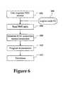
- step 502the method for inserting, transmitting and using the Logical Node ID in accordance with the present invention is shown.
- the processbegins in step 502 by generating a unique Logical Node ID for each node and inserting such Logical Node ID into the data stream.
- step 504the Logical Node ID signal is transmitted as part of the data stream over the information network 108.
- step 506the data stream including the Logical Node ID is received at a subscriber station.
- step 508uses the Logical Node ID received to create a new message that includes the Logical Node ID.
- the message created in step 508is then sent in step 510 to the headend.
- the combiner or headendsets the Logical Node membership using this message in step 512, and thus, the topology of the network is known by the system 100c.
- the system 100ccan then use the information stored at the headend to switch data streams using the TPM 102b and DVM module 106b, such that programs will be correctly routed even though changes may have been made to the network manually or automatically.
- the TPM 102b and DVM module 106bcan be assured to send data to the appropriate subscriber stations.
- FIG. 6is a flowchart showing an embodiment where the role of the master SCM in identifying the corresponding SCM and the role of the hub in providing the channel allocation information to the subscriber station are eliminated.
- elimination of such actionsreduces the amount of time (and accompanying bandwidth) required to initiate VOD service.
- These stepsare eliminated by storing the address of the corresponding SCM together with the channel allocation information in the subscriber station.
- This informationcan be stored in the subscriber station in a nonvolatile memory such as a flash memory as typically found on subscriber stations such as digital set-top boxes.
- the userrequests VOD by way of the corresponding subscriber station.
- the subscriber stationreads the Program Map Table (PMT) and at step 604 receives the periodic transmission of the Logical Node ID.
- PMTProgram Map Table
- the IP address of the SCMwhich is stored in the subscriber station and its listener port number are used to make a User Datagram Protocol (UDP or TCP - Transmission Control Protocol) connection between the SCM and the subscriber station.
- UDPUser Datagram Protocol
- TCP - Transmission Control ProtocolTransmission Control Protocol
- FIG. 7is a flowchart showing communication between a set-top box (portion of a suscriber station) and the headend 304 to request and to receive video-on-demand (VOD) services, such as transmission of movies or other video programs.
- VODvideo-on-demand
- the userrequests VOD services, by entering appropriate inputs into the set-top box.
- the corresponding hubresponds to the request for VOD service by identifying, from information stored in the hub, an SCM that is functioning as a master SCM.
- the subscriber stationinitiates communication with the master SCM to establish a connection between the master SCM and the subscriber station. This connection is preferably established in accordance with the User Datagram Protocol (UDP) of the TCP/IP suite of protocols.
- UDPUser Datagram Protocol
- the huballocates a channel for transmission of the requested video program from the corresponding hub to the subscriber station. Also at step 710, the master SCM allocates a program identifier (PID) to uniquely identify the requested program. Transmission of the Logical Node ID at step 712 is performed periodically; such as for example, every one-tenth of a second, and the Logical Node ID can therefore be expected to be received by the subscriber station.
- the channel for transmission of the requested video program from the corresponding hub to the subscriber station, and the program identifier (PID)may be predefined (step 730).
- a copy of a distributed packet having the predefined channel and PIDmay be stored at the subscriber station using local storage to reduce the latency in starting interactive sessions where the contents provide temporary copies of the information contained in the distributed packet.
- steps 700-710may be replaced with the single step 730 of identifying the predefined channel and PID after which the method continues with that information in step 714.
- the subscriber stationreceives the Logical Node ID, it has the necessary information to communicate with the corresponding SCM, and at step 714 the UDP connection between the master SCM and the subscriber station is terminated.
- a UDP connectionis established between the identified SCM and the subscriber station. Once established at 716, transmission of the requested program by the SCM to the requesting subscriber station occurs 718 until the transmission is terminated at step 720.
Landscapes
- Engineering & Computer Science (AREA)
- Signal Processing (AREA)
- Multimedia (AREA)
- Computer Networks & Wireless Communication (AREA)
- Business, Economics & Management (AREA)
- General Business, Economics & Management (AREA)
- Two-Way Televisions, Distribution Of Moving Picture Or The Like (AREA)
- Data Exchanges In Wide-Area Networks (AREA)
- Communication Control (AREA)
Abstract
Description
According to a second aspect, the invention provides an apparatus operable to identifylogical nodes in a heterogeneous network supporting session-based routing orswitching of information flow, said network having a source, a plurality of logicalnodes and a plurality of devices, said apparatus comprising: an information distributoroperable to: receive from said source, a signal comprising at least one logical identifierindicative of one of said plurality of logical nodes; transmit said signal to at least oneof said plurality of devices associated with said logical node corresponding to said atleast one logical identifier; receive from each of said at least one of said plurality ofdevices a message identifying the device and said at least one logical identifier;transmit said message towards said source, said message being adapted to enable theassigning of said at least one logical identifier to said at least one device, independentof a physical organisation of said at least one device on said network (108), and toenable configuration of said network.
1-4,
Claims (29)
- A method for logical node identification in a heterogeneous network (108)supporting session-based routing or switching of information flow, said network (108)having a source (104, 304), a plurality of logical nodes and a plurality of devices, saidmethod being performed by an information distributor (110, 110b, 304) andcomprising:receiving from said source (104, 304) a signal having associated with it at leastone logical identifier indicative of one of said plurality of logical nodes;transmitting said signal toward at least one device of said plurality of devices(220a to 220n) associated with a logical node corresponding to said at least one logicalidentifier;receiving from each of said at least one device a message identifying said atleast one device and said at least one logical identifier; andtransmitting said message towards said source (104, 304), said message beingadapted to enable the assigning of said at least one logical identifier to said at least onedevice, independent of a physical organisation of said at least one device on saidnetwork (108) and to enable configuration of said network (108).
- The method as claimed in claim 1, wherein said source of said signal is part of aheadend of said network.
- The method as claimed in claim 1, wherein at least one of said at least onedevices is a requesting subscriber station.
- The method as claimed in claim 3 comprising the step of switchingtransmission of said signal to a logical node and switching said message from saidrequesting subscriber station to a control module.
- The method as claimed in claim 1, wherein said network acts as an intermediarybetween said information distributor (110, 110b) and said source of said signal (104,304).
- The method as claimed in claim 1, wherein said information distributorcomprises:a receiver/descrambler (210a); anda telephone (214a).
- The method as claimed in claim 1, wherein said signal is received from at leastone satellite base station via a corresponding satellite.
- The method as claimed in claim 3, comprising:from said source (104, 304) using one modulator of a plurality of modulatorscommunicating with said requesting subscriber station, towards said requestingsubscriber station.providing said at least one logical identifier;assigning each of said at least one logical identifiers to said signal;transmitting each of said assigned logical identifiers and said signal
- The method as claimed in claim 8, wherein said message receiving step comprises:subscriber station to identify said given modulator in said plurality of modulators.sending said logical identifier and information identifying said requestingsubscriber station from said requesting subscriber station towards said source (104,304);using said at least one logical identifier received from said requesting
- The method as claimed in claim 8, wherein said source (104, 304) includes adigital video modulator that uses DVM quadrature amplitude modulation (QAM).
- The method as claimed in claim 8, comprising identifying a pre-defined channeland a packet identification number from a copy of a distributed packet stored at saidrequesting subscriber station.
- The method as claimed in claim 1, comprising:connecting a first device for communication with said network at a firstlocation;receiving a logical identifier along with a data stream at said first device;sending said received logical identifier and first device identificationinformation towards said source;using said message to identify a sending modulator that is communicatingwith said first device.
- The method as claimed in claim 1 further comprising the steps of:disconnecting said at least one device from communication with saidnetwork at a first location;re-connecting said at least one device for communication with saidnetwork at a second location;transmitting said signal from said source (104, 304) towards said at least onedevice, a data stream of said signal comprising said at least one logical identifierassociated with said signal;receiving a new message from said at least one device, said new messagebeing adapted to subsequently identify a new sending modulator that is communicatingwith said at least one device;transmitting said new message towards said source (104, 304).
- An apparatus operable to identify logical nodes in a heterogeneous networksupporting session-based routing or switching of information flow, said network (108)having a source (104, 304), a plurality of logical nodes and a plurality of devices, saidapparatus comprising:an information distributor (110, 110b, 304) operable to:receive from said source (104, 304), a signal comprising at least one logicalidentifier indicative of one of said plurality of logical nodes;transmit said signal to at least one of said plurality of devices (220a to 220n)associated with said logical node corresponding to said at least one logical identifier;receive from each of said at least one of said plurality of devices a messageidentifying the device and said at least one logical identifier;transmit said message towards said source (104, 304), said message beingadapted to enable the assigning of said at least one logical identifier to said at least onedevice, independent of a physical organisation of said at least one device on saidnetwork (108), and to enable configuration of said network (108).
- The apparatus as claimed in claim 14, wherein said plurality of devicescomprises a plurality of subscriber stations.
- The apparatus as claimed in claim 14, wherein said information distributor(304) forms a part of a headend of said network.
- The apparatus as claimed in claim 14 or 15, wherein said network acts as anintermediary between said information distributor (110, 110b) and said source.
- The apparatus as claimed in claim 14 or 15, wherein said network comprises atleast one base station communicative with at least one satellite.
- The apparatus as claimed in claim 14, wherein said information distributorcomprises:a receiver/descrambler (210a); anda telephone (214a).
- The apparatus as claimed in claim 14, operable to transmit video programs oversaid network in response to program requests from said plurality of subscriber stations,said at least one subscriber station being coupled to said network by a correspondingone of a plurality of hubs, said apparatus comprising:a plurality of control modules in said source (104, 304), each of said controlmodules controlling transmission of requested programs to said plurality of subscriberstations and having a node identifier operable to generate said at least one logicalidentifier, said at least one logical identifier being indicative of a correspondence between said hub that couples said at least one subscriber station to said network and acorresponding one of said control modules.
- Apparatus according to claim 14 or claim 20, wherein said node identificationvalue comprises a single packet for all hubs.
- The apparatus as claimed in claim 20 or 21, wherein said node identifier assignssaid at least one logical identifier by periodically causing transmission of said logicalidentifier to a corresponding one of said plurality of hubs.
- The apparatus as claimed in any one of claims 20 to 22, wherein each of saidplurality of hubs is operable to couple coaxial portions of said network to fibreportions of said network and wherein at least a first channel and a second channel areallocated between each of said hubs and corresponding ones of said plurality ofsubscriber stations, said apparatus comprising:program identifying means, responsive to a program request from one of saidplurality of subscriber stations by providing that subscriber station with frequencyinformation and a program identifier (PID) indicative of a program corresponding tosaid program request; andtransmission means, responsive to said program identifying means, to causetransmission of said program to said subscriber station that sent said program request.
- The apparatus as claimed in claim 23, wherein said network comprises anetwork controller operable to assign to one of said plurality of subscriber stations, achannel for transmission of a requested program, said network beingcharacterised byhaving a first bandwidth between said source (104, 304) and said network controllerand a second bandwidth between said network controller and each of said plurality ofsubscriber stations such that said second bandwidth is lower than said first bandwidthand wherein said at least one logical identifier uniquely identifies said networkcontroller as a corresponding network controller and said program identifier (PID)uniquely identifies said requested program.
- The apparatus as claimed in claim 20 or 23, comprising a master control modulefor assigning each of said plurality of control modules to at least a first correspondingone of said plurality of hubs.
- The apparatus as claimed in claim 25, wherein said master control moduleresponds to a request from any one of said plurality of subscriber stations byidentifying said requesting subscribing station with a corresponding one of saidcontrol modules.
- The apparatus as claimed in claim 25 or 26, wherein a first subscriber stationof said plurality of subscriber stations transmits said at least one logical identifier tosaid master control module.
- The apparatus as claimed in claim 27, wherein said master control modulecauses a corresponding one of said plurality of control modules to transmit requestedprograms to said first subscriber station using said at least one logical identifiertransmitted by said first subscriber station to said master control module.
- The apparatus as claimed in claim 28, wherein said master control moduleselects a digital video modulator and a channel for transmitting requested programs tosaid first subscriber station using said at least one logical identifier transmitted by saidfirst subscriber station to said master control module.
Applications Claiming Priority (5)
| Application Number | Priority Date | Filing Date | Title |
|---|---|---|---|
| US10934198P | 1998-11-20 | 1998-11-20 | |
| US109341P | 1998-11-20 | ||
| US436934 | 1999-11-08 | ||
| US09/436,934US6697376B1 (en) | 1998-11-20 | 1999-11-08 | Logical node identification in an information transmission network |
| PCT/US1999/027492WO2000031921A2 (en) | 1998-11-20 | 1999-11-19 | Logical node identification in an information transmission network |
Publications (2)
| Publication Number | Publication Date |
|---|---|
| EP1131981A2 EP1131981A2 (en) | 2001-09-12 |
| EP1131981B1true EP1131981B1 (en) | 2004-08-04 |
Family
ID=26806880
Family Applications (1)
| Application Number | Title | Priority Date | Filing Date |
|---|---|---|---|
| EP99965009AExpired - LifetimeEP1131981B1 (en) | 1998-11-20 | 1999-11-19 | Logical node identification in an information transmission network |
Country Status (7)
| Country | Link |
|---|---|
| US (4) | US6697376B1 (en) |
| EP (1) | EP1131981B1 (en) |
| JP (1) | JP4653888B2 (en) |
| AT (1) | ATE272931T1 (en) |
| CA (1) | CA2351732C (en) |
| DE (1) | DE69919200T2 (en) |
| WO (1) | WO2000031921A2 (en) |
Families Citing this family (107)
| Publication number | Priority date | Publication date | Assignee | Title |
|---|---|---|---|---|
| US6697376B1 (en)* | 1998-11-20 | 2004-02-24 | Diva Systems Corporation | Logical node identification in an information transmission network |
| US7213061B1 (en)* | 1999-04-29 | 2007-05-01 | Amx Llc | Internet control system and method |
| US6657646B2 (en)* | 1999-06-08 | 2003-12-02 | Amx Corporation | System and method for multimedia display |
| US7540012B1 (en)* | 1999-06-08 | 2009-05-26 | International Business Machines Corporation | Video on demand configuring, controlling and maintaining |
| US7150031B1 (en)* | 2000-06-09 | 2006-12-12 | Scientific-Atlanta, Inc. | System and method for reminders of upcoming rentable media offerings |
| US6986156B1 (en)* | 1999-06-11 | 2006-01-10 | Scientific Atlanta, Inc | Systems and methods for adaptive scheduling and dynamic bandwidth resource allocation management in a digital broadband delivery system |
| US7992163B1 (en)* | 1999-06-11 | 2011-08-02 | Jerding Dean F | Video-on-demand navigational system |
| US7010801B1 (en)* | 1999-06-11 | 2006-03-07 | Scientific-Atlanta, Inc. | Video on demand system with parameter-controlled bandwidth deallocation |
| US6817028B1 (en)* | 1999-06-11 | 2004-11-09 | Scientific-Atlanta, Inc. | Reduced screen control system for interactive program guide |
| US20060059525A1 (en)* | 1999-12-13 | 2006-03-16 | Jerding Dean F | Media services window configuration system |
| AU775889B2 (en)* | 2000-01-13 | 2004-08-19 | Ncube Corporation | Method and apparatus for identifying a signal route for delivery of video-on-demand to a subscriber terminal |
| US7310671B1 (en)* | 2000-02-10 | 2007-12-18 | Paradyne Corporation | System and method for a trouble shooting portal to allow temporary management access to a communication device |
| BR0108714A (en)* | 2000-03-02 | 2002-11-26 | Scientific Atlanta | Apparatus and method for providing a plurality of initial interactive program guide arrangements |
| US8516525B1 (en) | 2000-06-09 | 2013-08-20 | Dean F. Jerding | Integrated searching system for interactive media guide |
| US7200857B1 (en)* | 2000-06-09 | 2007-04-03 | Scientific-Atlanta, Inc. | Synchronized video-on-demand supplemental commentary |
| US20020007485A1 (en)* | 2000-04-03 | 2002-01-17 | Rodriguez Arturo A. | Television service enhancements |
| US7975277B1 (en)* | 2000-04-03 | 2011-07-05 | Jerding Dean F | System for providing alternative services |
| US7934232B1 (en)* | 2000-05-04 | 2011-04-26 | Jerding Dean F | Navigation paradigm for access to television services |
| US8069259B2 (en)* | 2000-06-09 | 2011-11-29 | Rodriguez Arturo A | Managing removal of media titles from a list |
| US7096257B2 (en) | 2000-06-15 | 2006-08-22 | Forster Energy Llc | Automatic assignment of addresses to nodes in a network |
| US7962370B2 (en)* | 2000-06-29 | 2011-06-14 | Rodriguez Arturo A | Methods in a media service system for transaction processing |
| US7340759B1 (en)* | 2000-11-10 | 2008-03-04 | Scientific-Atlanta, Inc. | Systems and methods for adaptive pricing in a digital broadband delivery system |
| US20020129359A1 (en)* | 2000-11-27 | 2002-09-12 | Lichner Randall Manton | Cross platform system and method for the management and distribution of pay per view video on demand |
| US7346918B2 (en)* | 2000-12-27 | 2008-03-18 | Z-Band, Inc. | Intelligent device system and method for distribution of digital signals on a wideband signal distribution system |
| US7627887B2 (en)* | 2001-04-30 | 2009-12-01 | Scientific- Atlanta, Inc. | System and method for multicasting packets in a subscriber network |
| US7406029B1 (en)* | 2001-06-28 | 2008-07-29 | Netapp, Inc. | Fault tolerant optical data communication network having auto discovery |
| US7512964B2 (en) | 2001-06-29 | 2009-03-31 | Cisco Technology | System and method for archiving multiple downloaded recordable media content |
| US7526788B2 (en) | 2001-06-29 | 2009-04-28 | Scientific-Atlanta, Inc. | Graphic user interface alternate download options for unavailable PRM content |
| US8006262B2 (en) | 2001-06-29 | 2011-08-23 | Rodriguez Arturo A | Graphic user interfaces for purchasable and recordable media (PRM) downloads |
| US7496945B2 (en)* | 2001-06-29 | 2009-02-24 | Cisco Technology, Inc. | Interactive program guide for bidirectional services |
| US7346332B2 (en)* | 2002-01-25 | 2008-03-18 | Ksc Industries Incorporated | Wired, wireless, infrared, and powerline audio entertainment systems |
| US8103009B2 (en)* | 2002-01-25 | 2012-01-24 | Ksc Industries, Inc. | Wired, wireless, infrared, and powerline audio entertainment systems |
| US7853341B2 (en)* | 2002-01-25 | 2010-12-14 | Ksc Industries, Inc. | Wired, wireless, infrared, and powerline audio entertainment systems |
| US7334251B2 (en)* | 2002-02-11 | 2008-02-19 | Scientific-Atlanta, Inc. | Management of television advertising |
| US7373414B2 (en)* | 2002-08-29 | 2008-05-13 | Amx Llc | Multi-media system and method for simultaneously delivering multi-media data to multiple destinations |
| US7219367B2 (en)* | 2002-09-09 | 2007-05-15 | Scientific-Atlanta, Inc. | Backup communication modes |
| US7224366B2 (en)* | 2002-10-17 | 2007-05-29 | Amx, Llc | Method and system for control system software |
| US20040210927A1 (en)* | 2003-04-21 | 2004-10-21 | Bahr Charles C. | Multicasting systems using distributed user authentication |
| US7733915B2 (en)* | 2003-05-01 | 2010-06-08 | Genesis Microchip Inc. | Minimizing buffer requirements in a digital video system |
| US20040218599A1 (en)* | 2003-05-01 | 2004-11-04 | Genesis Microchip Inc. | Packet based video display interface and methods of use thereof |
| US8204076B2 (en)* | 2003-05-01 | 2012-06-19 | Genesis Microchip Inc. | Compact packet based multimedia interface |
| US7839860B2 (en)* | 2003-05-01 | 2010-11-23 | Genesis Microchip Inc. | Packet based video display interface |
| US20040221315A1 (en)* | 2003-05-01 | 2004-11-04 | Genesis Microchip Inc. | Video interface arranged to provide pixel data independent of a link character clock |
| US7567592B2 (en)* | 2003-05-01 | 2009-07-28 | Genesis Microchip Inc. | Packet based video display interface enumeration method |
| US8059673B2 (en)* | 2003-05-01 | 2011-11-15 | Genesis Microchip Inc. | Dynamic resource re-allocation in a packet based video display interface |
| US20040221312A1 (en)* | 2003-05-01 | 2004-11-04 | Genesis Microchip Inc. | Techniques for reducing multimedia data packet overhead |
| US7620062B2 (en)* | 2003-05-01 | 2009-11-17 | Genesis Microchips Inc. | Method of real time optimizing multimedia packet transmission rate |
| US7405719B2 (en)* | 2003-05-01 | 2008-07-29 | Genesis Microchip Inc. | Using packet transfer for driving LCD panel driver electronics |
| US20040218624A1 (en)* | 2003-05-01 | 2004-11-04 | Genesis Microchip Inc. | Packet based closed loop video display interface with periodic status checks |
| US7088741B2 (en)* | 2003-05-01 | 2006-08-08 | Genesis Microchip Inc. | Using an auxilary channel for video monitor training |
| US6992987B2 (en)* | 2003-05-01 | 2006-01-31 | Genesis Microchip Inc. | Enumeration method for the link clock rate and the pixel/audio clock rate |
| US8068485B2 (en) | 2003-05-01 | 2011-11-29 | Genesis Microchip Inc. | Multimedia interface |
| US7068686B2 (en) | 2003-05-01 | 2006-06-27 | Genesis Microchip Inc. | Method and apparatus for efficient transmission of multimedia data packets |
| US7424558B2 (en)* | 2003-05-01 | 2008-09-09 | Genesis Microchip Inc. | Method of adaptively connecting a video source and a video display |
| US7800623B2 (en)* | 2003-09-18 | 2010-09-21 | Genesis Microchip Inc. | Bypassing pixel clock generation and CRTC circuits in a graphics controller chip |
| US7487273B2 (en)* | 2003-09-18 | 2009-02-03 | Genesis Microchip Inc. | Data packet based stream transport scheduler wherein transport data link does not include a clock line |
| US7613300B2 (en)* | 2003-09-26 | 2009-11-03 | Genesis Microchip Inc. | Content-protected digital link over a single signal line |
| US7634090B2 (en)* | 2003-09-26 | 2009-12-15 | Genesis Microchip Inc. | Packet based high definition high-bandwidth digital content protection |
| US9247207B2 (en)* | 2003-11-13 | 2016-01-26 | Arris Enterprises, Inc. | System to provide index and metadata for content on demand |
| US8161388B2 (en)* | 2004-01-21 | 2012-04-17 | Rodriguez Arturo A | Interactive discovery of display device characteristics |
| US7483538B2 (en) | 2004-03-02 | 2009-01-27 | Ksc Industries, Inc. | Wireless and wired speaker hub for a home theater system |
| US20070211691A1 (en)* | 2004-09-09 | 2007-09-13 | Barber Ronald W | Method, system and computer program using standard interfaces for independent device controllers |
| US20060067341A1 (en)* | 2004-09-09 | 2006-03-30 | Barber Ronald W | Method, system and computer program using standard interfaces for independent device controllers |
| US20060087047A1 (en)* | 2004-10-22 | 2006-04-27 | Mathur Ashok N | Fluid mixing apparatus |
| US7342584B2 (en)* | 2004-11-18 | 2008-03-11 | Amx, Llc | Method and computer program for implementing interactive bargraphs of any shape or design on a graphical user interface |
| US8214465B2 (en)* | 2005-04-27 | 2012-07-03 | Comcast Cable Holdings, Llc | Method and system of transporting media signals and allocating assets |
| KR101171180B1 (en)* | 2005-07-15 | 2012-08-20 | 삼성전자주식회사 | Liquid crystal display |
| US20070022459A1 (en) | 2005-07-20 | 2007-01-25 | Gaebel Thomas M Jr | Method and apparatus for boundary-based network operation |
| US8074248B2 (en) | 2005-07-26 | 2011-12-06 | Activevideo Networks, Inc. | System and method for providing video content associated with a source image to a television in a communication network |
| US8441963B2 (en)* | 2005-08-04 | 2013-05-14 | General Instrument Corporation | IP multicast management and service provision system and method |
| US8189472B2 (en) | 2005-09-07 | 2012-05-29 | Mcdonald James F | Optimizing bandwidth utilization to a subscriber premises |
| AU2006287639C1 (en) | 2005-09-07 | 2012-06-28 | Open Invention Network, Llc | Method and computer program for device configuration |
| EP2477414A3 (en)* | 2006-09-29 | 2014-03-05 | Avinity Systems B.V. | Method for assembling a video stream, system and computer software |
| US20080201736A1 (en)* | 2007-01-12 | 2008-08-21 | Ictv, Inc. | Using Triggers with Video for Interactive Content Identification |
| US9826197B2 (en)* | 2007-01-12 | 2017-11-21 | Activevideo Networks, Inc. | Providing television broadcasts over a managed network and interactive content over an unmanaged network to a client device |
| US9042454B2 (en)* | 2007-01-12 | 2015-05-26 | Activevideo Networks, Inc. | Interactive encoded content system including object models for viewing on a remote device |
| US8522281B1 (en) | 2007-04-30 | 2013-08-27 | Google Inc. | Head end generalization |
| US20090094658A1 (en)* | 2007-10-09 | 2009-04-09 | Genesis Microchip Inc. | Methods and systems for driving multiple displays |
| US20090219932A1 (en)* | 2008-02-04 | 2009-09-03 | Stmicroelectronics, Inc. | Multi-stream data transport and methods of use |
| US20090262667A1 (en)* | 2008-04-21 | 2009-10-22 | Stmicroelectronics, Inc. | System and method for enabling topology mapping and communication between devices in a network |
| JP2011526134A (en)* | 2008-06-25 | 2011-09-29 | アクティブビデオ ネットワークス, インコーポレイテッド | Provision of interactive content to client devices via TV broadcast via unmanaged network and unmanaged network |
| WO2010062456A1 (en)* | 2008-09-26 | 2010-06-03 | Bae Systems Information And Electronic Systems Integration Inc. | Media access control protocol for multiuser detection enabled ad-hoc wireless communications |
| WO2010045358A1 (en) | 2008-10-14 | 2010-04-22 | Cochlear Americas | An implantable hearing prosthesis |
| US20100183004A1 (en)* | 2009-01-16 | 2010-07-22 | Stmicroelectronics, Inc. | System and method for dual mode communication between devices in a network |
| US8429440B2 (en)* | 2009-05-13 | 2013-04-23 | Stmicroelectronics, Inc. | Flat panel display driver method and system |
| US8156238B2 (en) | 2009-05-13 | 2012-04-10 | Stmicroelectronics, Inc. | Wireless multimedia transport method and apparatus |
| US8860888B2 (en)* | 2009-05-13 | 2014-10-14 | Stmicroelectronics, Inc. | Method and apparatus for power saving during video blanking periods |
| US8760461B2 (en) | 2009-05-13 | 2014-06-24 | Stmicroelectronics, Inc. | Device, system, and method for wide gamut color space support |
| US8582452B2 (en) | 2009-05-18 | 2013-11-12 | Stmicroelectronics, Inc. | Data link configuration by a receiver in the absence of link training data |
| US8468285B2 (en)* | 2009-05-18 | 2013-06-18 | Stmicroelectronics, Inc. | Operation of video source and sink with toggled hot plug detection |
| US8291207B2 (en)* | 2009-05-18 | 2012-10-16 | Stmicroelectronics, Inc. | Frequency and symbol locking using signal generated clock frequency and symbol identification |
| US8370554B2 (en)* | 2009-05-18 | 2013-02-05 | Stmicroelectronics, Inc. | Operation of video source and sink with hot plug detection not asserted |
| US9237381B2 (en)* | 2009-08-06 | 2016-01-12 | Time Warner Cable Enterprises Llc | Methods and apparatus for local channel insertion in an all-digital content distribution network |
| US9635421B2 (en) | 2009-11-11 | 2017-04-25 | Time Warner Cable Enterprises Llc | Methods and apparatus for audience data collection and analysis in a content delivery network |
| US8671234B2 (en) | 2010-05-27 | 2014-03-11 | Stmicroelectronics, Inc. | Level shifting cable adaptor and chip system for use with dual-mode multi-media device |
| CA2814070A1 (en) | 2010-10-14 | 2012-04-19 | Activevideo Networks, Inc. | Streaming digital video between video devices using a cable television system |
| US8930979B2 (en) | 2010-11-11 | 2015-01-06 | Time Warner Cable Enterprises Llc | Apparatus and methods for identifying and characterizing latency in a content delivery network |
| US10148623B2 (en) | 2010-11-12 | 2018-12-04 | Time Warner Cable Enterprises Llc | Apparatus and methods ensuring data privacy in a content distribution network |
| WO2012138660A2 (en) | 2011-04-07 | 2012-10-11 | Activevideo Networks, Inc. | Reduction of latency in video distribution networks using adaptive bit rates |
| EP2815582B1 (en) | 2012-01-09 | 2019-09-04 | ActiveVideo Networks, Inc. | Rendering of an interactive lean-backward user interface on a television |
| US9123084B2 (en) | 2012-04-12 | 2015-09-01 | Activevideo Networks, Inc. | Graphical application integration with MPEG objects |
| WO2014145921A1 (en) | 2013-03-15 | 2014-09-18 | Activevideo Networks, Inc. | A multiple-mode system and method for providing user selectable video content |
| TWI578836B (en) | 2013-05-10 | 2017-04-11 | 瑞雷2股份有限公司 | Multi-tenant virtual access point-network resources virtualization |
| US9294785B2 (en) | 2013-06-06 | 2016-03-22 | Activevideo Networks, Inc. | System and method for exploiting scene graph information in construction of an encoded video sequence |
| US9219922B2 (en) | 2013-06-06 | 2015-12-22 | Activevideo Networks, Inc. | System and method for exploiting scene graph information in construction of an encoded video sequence |
| EP3005712A1 (en) | 2013-06-06 | 2016-04-13 | ActiveVideo Networks, Inc. | Overlay rendering of user interface onto source video |
| US9972682B2 (en)* | 2016-01-22 | 2018-05-15 | International Business Machines Corporation | Low resistance source drain contact formation |
Family Cites Families (32)
| Publication number | Priority date | Publication date | Assignee | Title |
|---|---|---|---|---|
| US3378130A (en)* | 1966-10-12 | 1968-04-16 | Wallace Systems Inc W J | Unloading machine for tankers or the like |
| US5412720A (en)* | 1990-09-28 | 1995-05-02 | Ictv, Inc. | Interactive home information system |
| US5434678A (en)* | 1993-01-11 | 1995-07-18 | Abecassis; Max | Seamless transmission of non-sequential video segments |
| JP2761356B2 (en)* | 1993-06-25 | 1998-06-04 | 松下電工株式会社 | Hub self-number setting method |
| US5481542A (en)* | 1993-11-10 | 1996-01-02 | Scientific-Atlanta, Inc. | Interactive information services control system |
| JPH07193594A (en)* | 1993-12-27 | 1995-07-28 | Matsushita Electric Ind Co Ltd | Inter-network connection control device |
| JPH07274154A (en)* | 1994-03-28 | 1995-10-20 | Sumitomo Electric Ind Ltd | Video demand system and video demand control device for CATV system |
| US5539920A (en)* | 1994-04-28 | 1996-07-23 | Thomson Consumer Electronics, Inc. | Method and apparatus for processing an audio video interactive signal |
| JP2601189B2 (en) | 1994-05-20 | 1997-04-16 | 日本電気株式会社 | Video on demand system |
| JPH07336460A (en)* | 1994-06-03 | 1995-12-22 | Hitachi Ltd | Data communication device |
| US5619249A (en)* | 1994-09-14 | 1997-04-08 | Time Warner Entertainment Company, L.P. | Telecasting service for providing video programs on demand with an interactive interface for facilitating viewer selection of video programs |
| US5650994A (en) | 1995-05-16 | 1997-07-22 | Bell Atlantic Network Services, Inc. | Operation support system for service creation and network provisioning for video dial tone networks |
| CA2222603C (en) | 1995-06-22 | 2002-11-26 | Scientific-Atlanta, Inc. | Hybrid fiber coax communications system |
| US5594702A (en)* | 1995-06-28 | 1997-01-14 | National Semiconductor Corporation | Multi-first-in-first-out memory circuit |
| US5734652A (en)* | 1995-09-27 | 1998-03-31 | Microsoft Corporation | ATM extended autoregistration and VPI/VCI assignment in a hybrid fiber-coax cable network |
| US5671217A (en) | 1995-12-14 | 1997-09-23 | Time Warner Entertainment Co. L.P. | Scalable communications network employing shared logical nodes |
| US5835723A (en)* | 1995-12-28 | 1998-11-10 | Intel Corporation | Dynamic assignment of multicast addresses |
| US5999970A (en)* | 1996-04-10 | 1999-12-07 | World Gate Communications, Llc | Access system and method for providing interactive access to an information source through a television distribution system |
| JPH09284748A (en)* | 1996-04-19 | 1997-10-31 | Sony Corp | System and method for two-way information transmission |
| US5841468A (en)* | 1996-04-26 | 1998-11-24 | Convergence. Com | System and method for routing data messages through a cable transmission system |
| US5905726A (en)* | 1996-05-21 | 1999-05-18 | Cisco Technology, Inc. | Broadband communication system having a virtual circuit space switch |
| US5878325A (en)* | 1996-07-12 | 1999-03-02 | At&T Corp | Hybrid fiber-coax system having at least one digital fiber node |
| JP3549676B2 (en)* | 1996-07-24 | 2004-08-04 | 富士通株式会社 | Terminal ID automatic assignment method |
| JP3557058B2 (en)* | 1996-11-27 | 2004-08-25 | 株式会社東芝 | Communication device |
| US6253375B1 (en)* | 1997-01-13 | 2001-06-26 | Diva Systems Corporation | System for interactively distributing information services |
| US6308328B1 (en)* | 1997-01-17 | 2001-10-23 | Scientific-Atlanta, Inc. | Usage statistics collection for a cable data delivery system |
| US6295298B1 (en)* | 1997-04-11 | 2001-09-25 | Scientific-Atlanta, Inc. | Method of dynamically assigning a logical network address and a link address |
| DE19741885A1 (en)* | 1997-09-23 | 1999-03-25 | Cit Alcatel | Device for assigning transmission channels at the end points of a service-on-demand system |
| US6378130B1 (en)* | 1997-10-20 | 2002-04-23 | Time Warner Entertainment Company | Media server interconnect architecture |
| JP3886243B2 (en)* | 1998-03-18 | 2007-02-28 | 富士通株式会社 | Information distribution device |
| US7103065B1 (en)* | 1998-10-30 | 2006-09-05 | Broadcom Corporation | Data packet fragmentation in a cable modem system |
| US6697376B1 (en)* | 1998-11-20 | 2004-02-24 | Diva Systems Corporation | Logical node identification in an information transmission network |
- 1999
- 1999-11-08USUS09/436,934patent/US6697376B1/ennot_activeExpired - Lifetime
- 1999-11-19CACA2351732Apatent/CA2351732C/ennot_activeExpired - Lifetime
- 1999-11-19DEDE69919200Tpatent/DE69919200T2/ennot_activeExpired - Lifetime
- 1999-11-19WOPCT/US1999/027492patent/WO2000031921A2/enactiveIP Right Grant
- 1999-11-19EPEP99965009Apatent/EP1131981B1/ennot_activeExpired - Lifetime
- 1999-11-19JPJP2000584640Apatent/JP4653888B2/ennot_activeExpired - Fee Related
- 1999-11-19ATAT99965009Tpatent/ATE272931T1/ennot_activeIP Right Cessation
- 2003
- 2003-09-16USUS10/663,256patent/US7203201B2/ennot_activeExpired - Lifetime
- 2007
- 2007-03-08USUS11/683,606patent/US8289993B2/ennot_activeExpired - Fee Related
- 2012
- 2012-09-07USUS13/606,578patent/US8918824B2/ennot_activeExpired - Fee Related
Also Published As
| Publication number | Publication date |
|---|---|
| US8918824B2 (en) | 2014-12-23 |
| DE69919200T2 (en) | 2005-08-18 |
| US6697376B1 (en) | 2004-02-24 |
| JP4653888B2 (en) | 2011-03-16 |
| US20070147418A1 (en) | 2007-06-28 |
| CA2351732C (en) | 2014-05-27 |
| US20040062270A1 (en) | 2004-04-01 |
| CA2351732A1 (en) | 2000-06-02 |
| ATE272931T1 (en) | 2004-08-15 |
| EP1131981A2 (en) | 2001-09-12 |
| US8289993B2 (en) | 2012-10-16 |
| WO2000031921A3 (en) | 2000-11-16 |
| DE69919200D1 (en) | 2004-09-09 |
| US7203201B2 (en) | 2007-04-10 |
| JP2002531001A (en) | 2002-09-17 |
| WO2000031921A8 (en) | 2000-10-05 |
| WO2000031921A2 (en) | 2000-06-02 |
| US20130024899A1 (en) | 2013-01-24 |
Similar Documents
| Publication | Publication Date | Title |
|---|---|---|
| EP1131981B1 (en) | Logical node identification in an information transmission network | |
| CA2682364C (en) | Bandwidth sensitive switched digital video content delivery | |
| JP4988116B2 (en) | Method and apparatus for identifying a signal path for transmission of video on demand to a subscriber terminal | |
| CA2663907C (en) | Atomic channel changes in a switched digital video system | |
| CA2629310C (en) | Quality of service management in a switched digital video environment | |
| CA2629313C (en) | Channel changes between services with differing bandwidth in a switched digital video system | |
| CA2680851C (en) | Switched digital video client reverse channel traffic reduction | |
| CA2663704C (en) | Bandwidth management in each network device in a switched digital video environment | |
| US20100050215A1 (en) | System and method for bandwidth handling |
Legal Events
| Date | Code | Title | Description |
|---|---|---|---|
| PUAI | Public reference made under article 153(3) epc to a published international application that has entered the european phase | Free format text:ORIGINAL CODE: 0009012 | |
| 17P | Request for examination filed | Effective date:20010525 | |
| AK | Designated contracting states | Kind code of ref document:A2 Designated state(s):AT BE CH CY DE DK ES FI FR GB GR IE IT LI LU MC NL PT SE | |
| AX | Request for extension of the european patent | Free format text:AL;LT;LV;MK;RO;SI | |
| 17Q | First examination report despatched | Effective date:20020820 | |
| GRAP | Despatch of communication of intention to grant a patent | Free format text:ORIGINAL CODE: EPIDOSNIGR1 | |
| GRAS | Grant fee paid | Free format text:ORIGINAL CODE: EPIDOSNIGR3 | |
| GRAA | (expected) grant | Free format text:ORIGINAL CODE: 0009210 | |
| AK | Designated contracting states | Kind code of ref document:B1 Designated state(s):AT BE CH CY DE DK ES FI FR GB GR IE IT LI LU MC NL PT SE | |
| PG25 | Lapsed in a contracting state [announced via postgrant information from national office to epo] | Ref country code:NL Free format text:LAPSE BECAUSE OF FAILURE TO SUBMIT A TRANSLATION OF THE DESCRIPTION OR TO PAY THE FEE WITHIN THE PRESCRIBED TIME-LIMIT Effective date:20040804 Ref country code:FI Free format text:LAPSE BECAUSE OF FAILURE TO SUBMIT A TRANSLATION OF THE DESCRIPTION OR TO PAY THE FEE WITHIN THE PRESCRIBED TIME-LIMIT Effective date:20040804 Ref country code:CY Free format text:LAPSE BECAUSE OF FAILURE TO SUBMIT A TRANSLATION OF THE DESCRIPTION OR TO PAY THE FEE WITHIN THE PRESCRIBED TIME-LIMIT Effective date:20040804 Ref country code:BE Free format text:LAPSE BECAUSE OF FAILURE TO SUBMIT A TRANSLATION OF THE DESCRIPTION OR TO PAY THE FEE WITHIN THE PRESCRIBED TIME-LIMIT Effective date:20040804 Ref country code:AT Free format text:LAPSE BECAUSE OF FAILURE TO SUBMIT A TRANSLATION OF THE DESCRIPTION OR TO PAY THE FEE WITHIN THE PRESCRIBED TIME-LIMIT Effective date:20040804 | |
| REG | Reference to a national code | Ref country code:GB Ref legal event code:FG4D | |
| REG | Reference to a national code | Ref country code:CH Ref legal event code:EP | |
| RAP2 | Party data changed (patent owner data changed or rights of a patent transferred) | Owner name:TV GATEWAY, LLC | |
| REG | Reference to a national code | Ref country code:IE Ref legal event code:FG4D | |
| REF | Corresponds to: | Ref document number:69919200 Country of ref document:DE Date of ref document:20040909 Kind code of ref document:P | |
| NLT2 | Nl: modifications (of names), taken from the european patent patent bulletin | Owner name:TV GATEWAY, LLC | |
| REG | Reference to a national code | Ref country code:CH Ref legal event code:NV Representative=s name:MICHELI & CIE INGENIEURS-CONSEILS | |
| PG25 | Lapsed in a contracting state [announced via postgrant information from national office to epo] | Ref country code:SE Free format text:LAPSE BECAUSE OF FAILURE TO SUBMIT A TRANSLATION OF THE DESCRIPTION OR TO PAY THE FEE WITHIN THE PRESCRIBED TIME-LIMIT Effective date:20041104 Ref country code:GR Free format text:LAPSE BECAUSE OF FAILURE TO SUBMIT A TRANSLATION OF THE DESCRIPTION OR TO PAY THE FEE WITHIN THE PRESCRIBED TIME-LIMIT Effective date:20041104 Ref country code:DK Free format text:LAPSE BECAUSE OF FAILURE TO SUBMIT A TRANSLATION OF THE DESCRIPTION OR TO PAY THE FEE WITHIN THE PRESCRIBED TIME-LIMIT Effective date:20041104 | |
| PG25 | Lapsed in a contracting state [announced via postgrant information from national office to epo] | Ref country code:ES Free format text:LAPSE BECAUSE OF FAILURE TO SUBMIT A TRANSLATION OF THE DESCRIPTION OR TO PAY THE FEE WITHIN THE PRESCRIBED TIME-LIMIT Effective date:20041115 | |
| RAP2 | Party data changed (patent owner data changed or rights of a patent transferred) | Owner name:SEDNA PATENT SERVICES, LLC | |
| PG25 | Lapsed in a contracting state [announced via postgrant information from national office to epo] | Ref country code:LU Free format text:LAPSE BECAUSE OF NON-PAYMENT OF DUE FEES Effective date:20041119 Ref country code:IE Free format text:LAPSE BECAUSE OF NON-PAYMENT OF DUE FEES Effective date:20041119 | |
| PG25 | Lapsed in a contracting state [announced via postgrant information from national office to epo] | Ref country code:MC Free format text:LAPSE BECAUSE OF NON-PAYMENT OF DUE FEES Effective date:20041130 | |
| NLT2 | Nl: modifications (of names), taken from the european patent patent bulletin | Owner name:SEDNA PATENT SERVICES, LLC | |
| NLV1 | Nl: lapsed or annulled due to failure to fulfill the requirements of art. 29p and 29m of the patents act | ||
| LTIE | Lt: invalidation of european patent or patent extension | Effective date:20040804 | |
| ET | Fr: translation filed | ||
| PLBE | No opposition filed within time limit | Free format text:ORIGINAL CODE: 0009261 | |
| STAA | Information on the status of an ep patent application or granted ep patent | Free format text:STATUS: NO OPPOSITION FILED WITHIN TIME LIMIT | |
| REG | Reference to a national code | Ref country code:CH Ref legal event code:PFA Owner name:SEDNA PATENT SERVICES, LLC Free format text:TV GATEWAY, LLC#1500 MARKET STREET 25TH FLOOR#PHILADELPHIA, PENNSYLVANIA 19102 (US) -TRANSFER TO- SEDNA PATENT SERVICES, LLC#1500 MARKET STREET 27TH FLOOR#PHILADELPHIA, PENNSYLVANIA 19102 (US) | |
| 26N | No opposition filed | Effective date:20050506 | |
| REG | Reference to a national code | Ref country code:FR Ref legal event code:CD | |
| REG | Reference to a national code | Ref country code:IE Ref legal event code:MM4A | |
| PG25 | Lapsed in a contracting state [announced via postgrant information from national office to epo] | Ref country code:PT Free format text:LAPSE BECAUSE OF NON-PAYMENT OF DUE FEES Effective date:20050104 | |
| PGFP | Annual fee paid to national office [announced via postgrant information from national office to epo] | Ref country code:CH Payment date:20071009 Year of fee payment:9 Ref country code:IT Payment date:20071120 Year of fee payment:9 | |
| REG | Reference to a national code | Ref country code:CH Ref legal event code:PL | |
| PG25 | Lapsed in a contracting state [announced via postgrant information from national office to epo] | Ref country code:IT Free format text:LAPSE BECAUSE OF NON-PAYMENT OF DUE FEES Effective date:20081119 | |
| PG25 | Lapsed in a contracting state [announced via postgrant information from national office to epo] | Ref country code:LI Free format text:LAPSE BECAUSE OF NON-PAYMENT OF DUE FEES Effective date:20081130 Ref country code:CH Free format text:LAPSE BECAUSE OF NON-PAYMENT OF DUE FEES Effective date:20081130 | |
| REG | Reference to a national code | Ref country code:GB Ref legal event code:732E Free format text:REGISTERED BETWEEN 20101104 AND 20101110 | |
| REG | Reference to a national code | Ref country code:DE Ref legal event code:R081 Ref document number:69919200 Country of ref document:DE Owner name:COMCAST IP HOLDINGS I, LLC, WILMINGTON, US Free format text:FORMER OWNER: SEDNA PATENT SERVICES, LLC, PHILADELPHIA, PA., US Effective date:20110309 | |
| REG | Reference to a national code | Ref country code:FR Ref legal event code:TP Owner name:COMCAST IP HOLDINGS I, LLC, US Effective date:20120730 | |
| REG | Reference to a national code | Ref country code:FR Ref legal event code:PLFP Year of fee payment:17 | |
| REG | Reference to a national code | Ref country code:FR Ref legal event code:PLFP Year of fee payment:18 | |
| REG | Reference to a national code | Ref country code:FR Ref legal event code:PLFP Year of fee payment:19 | |
| PGFP | Annual fee paid to national office [announced via postgrant information from national office to epo] | Ref country code:DE Payment date:20171129 Year of fee payment:19 Ref country code:FR Payment date:20171127 Year of fee payment:19 | |
| PGFP | Annual fee paid to national office [announced via postgrant information from national office to epo] | Ref country code:GB Payment date:20171127 Year of fee payment:19 | |
| REG | Reference to a national code | Ref country code:DE Ref legal event code:R119 Ref document number:69919200 Country of ref document:DE | |
| GBPC | Gb: european patent ceased through non-payment of renewal fee | Effective date:20181119 | |
| PG25 | Lapsed in a contracting state [announced via postgrant information from national office to epo] | Ref country code:FR Free format text:LAPSE BECAUSE OF NON-PAYMENT OF DUE FEES Effective date:20181130 Ref country code:DE Free format text:LAPSE BECAUSE OF NON-PAYMENT OF DUE FEES Effective date:20190601 | |
| PG25 | Lapsed in a contracting state [announced via postgrant information from national office to epo] | Ref country code:GB Free format text:LAPSE BECAUSE OF NON-PAYMENT OF DUE FEES Effective date:20181119 |