EP1131007B1 - Bioabsorbable surgical screw and washer system - Google Patents
Bioabsorbable surgical screw and washer systemDownload PDFInfo
- Publication number
- EP1131007B1 EP1131007B1EP99948510AEP99948510AEP1131007B1EP 1131007 B1EP1131007 B1EP 1131007B1EP 99948510 AEP99948510 AEP 99948510AEP 99948510 AEP99948510 AEP 99948510AEP 1131007 B1EP1131007 B1EP 1131007B1
- Authority
- EP
- European Patent Office
- Prior art keywords
- screw
- washer
- head
- shank
- diameter
- Prior art date
- Legal status (The legal status is an assumption and is not a legal conclusion. Google has not performed a legal analysis and makes no representation as to the accuracy of the status listed.)
- Expired - Lifetime
Links
- 238000000034methodMethods0.000claimsabstractdescription24
- 238000004519manufacturing processMethods0.000claimsabstractdescription7
- 239000000463materialSubstances0.000claimsdescription27
- 238000007373indentationMethods0.000claimsdescription6
- 238000001727in vivoMethods0.000claimsdescription4
- 210000002435tendonAnatomy0.000abstractdescription40
- 210000000988bone and boneAnatomy0.000abstractdescription33
- 210000000513rotator cuffAnatomy0.000abstractdescription15
- 210000001699lower legAnatomy0.000description22
- 230000008439repair processEffects0.000description13
- 238000001356surgical procedureMethods0.000description11
- 210000004095humeral headAnatomy0.000description10
- 210000001519tissueAnatomy0.000description9
- 230000006378damageEffects0.000description7
- 230000035876healingEffects0.000description7
- 239000007943implantSubstances0.000description6
- 238000003780insertionMethods0.000description6
- 230000037431insertionEffects0.000description6
- 230000007794irritationEffects0.000description6
- 210000004872soft tissueAnatomy0.000description6
- 208000014674injuryDiseases0.000description4
- 210000002758humerusAnatomy0.000description3
- 230000017074necrotic cell deathEffects0.000description3
- 230000002980postoperative effectEffects0.000description3
- 238000010079rubber tappingMethods0.000description3
- 210000000323shoulder jointAnatomy0.000description3
- 208000027418Wounds and injuryDiseases0.000description2
- 210000000845cartilageAnatomy0.000description2
- 229920001577copolymerPolymers0.000description2
- 230000000694effectsEffects0.000description2
- 238000003754machiningMethods0.000description2
- 229920001432poly(L-lactide)Polymers0.000description2
- 229920000642polymerPolymers0.000description2
- 238000012360testing methodMethods0.000description2
- 230000008733traumaEffects0.000description2
- 229920000954PolyglycolidePolymers0.000description1
- 208000035965Postoperative ComplicationsDiseases0.000description1
- 208000024288Rotator Cuff injuryDiseases0.000description1
- 239000012620biological materialSubstances0.000description1
- 230000015556catabolic processEffects0.000description1
- 238000006243chemical reactionMethods0.000description1
- 230000001010compromised effectEffects0.000description1
- 238000011109contaminationMethods0.000description1
- 238000005520cutting processMethods0.000description1
- 230000000115debilitative effectEffects0.000description1
- 238000006731degradation reactionMethods0.000description1
- 230000001419dependent effectEffects0.000description1
- 238000005553drillingMethods0.000description1
- 239000003814drugSubstances0.000description1
- 229940079593drugDrugs0.000description1
- 238000001125extrusionMethods0.000description1
- 239000000122growth hormoneSubstances0.000description1
- 238000001746injection mouldingMethods0.000description1
- 238000002595magnetic resonance imagingMethods0.000description1
- 230000005499meniscusEffects0.000description1
- 230000005012migrationEffects0.000description1
- 238000013508migrationMethods0.000description1
- 238000012986modificationMethods0.000description1
- 230000004048modificationEffects0.000description1
- 210000003205muscleAnatomy0.000description1
- 230000001009osteoporotic effectEffects0.000description1
- 229920000747poly(lactic acid)Polymers0.000description1
- 230000008569processEffects0.000description1
- 238000009877renderingMethods0.000description1
- 210000002303tibiaAnatomy0.000description1
- 230000002792vascularEffects0.000description1
Images


Classifications
- A—HUMAN NECESSITIES
- A61—MEDICAL OR VETERINARY SCIENCE; HYGIENE
- A61F—FILTERS IMPLANTABLE INTO BLOOD VESSELS; PROSTHESES; DEVICES PROVIDING PATENCY TO, OR PREVENTING COLLAPSING OF, TUBULAR STRUCTURES OF THE BODY, e.g. STENTS; ORTHOPAEDIC, NURSING OR CONTRACEPTIVE DEVICES; FOMENTATION; TREATMENT OR PROTECTION OF EYES OR EARS; BANDAGES, DRESSINGS OR ABSORBENT PADS; FIRST-AID KITS
- A61F2/00—Filters implantable into blood vessels; Prostheses, i.e. artificial substitutes or replacements for parts of the body; Appliances for connecting them with the body; Devices providing patency to, or preventing collapsing of, tubular structures of the body, e.g. stents
- A61F2/02—Prostheses implantable into the body
- A61F2/08—Muscles; Tendons; Ligaments
- A61F2/0811—Fixation devices for tendons or ligaments
- A—HUMAN NECESSITIES
- A61—MEDICAL OR VETERINARY SCIENCE; HYGIENE
- A61B—DIAGNOSIS; SURGERY; IDENTIFICATION
- A61B17/00—Surgical instruments, devices or methods
- A61B17/56—Surgical instruments or methods for treatment of bones or joints; Devices specially adapted therefor
- A61B17/58—Surgical instruments or methods for treatment of bones or joints; Devices specially adapted therefor for osteosynthesis, e.g. bone plates, screws or setting implements
- A61B17/68—Internal fixation devices, including fasteners and spinal fixators, even if a part thereof projects from the skin
- A61B17/84—Fasteners therefor or fasteners being internal fixation devices
- A61B17/86—Pins or screws or threaded wires; nuts therefor
- A61B17/8625—Shanks, i.e. parts contacting bone tissue
- A—HUMAN NECESSITIES
- A61—MEDICAL OR VETERINARY SCIENCE; HYGIENE
- A61B—DIAGNOSIS; SURGERY; IDENTIFICATION
- A61B17/00—Surgical instruments, devices or methods
- A61B17/56—Surgical instruments or methods for treatment of bones or joints; Devices specially adapted therefor
- A61B17/58—Surgical instruments or methods for treatment of bones or joints; Devices specially adapted therefor for osteosynthesis, e.g. bone plates, screws or setting implements
- A61B17/68—Internal fixation devices, including fasteners and spinal fixators, even if a part thereof projects from the skin
- A61B17/84—Fasteners therefor or fasteners being internal fixation devices
- A61B17/86—Pins or screws or threaded wires; nuts therefor
- A61B17/866—Material or manufacture
- A—HUMAN NECESSITIES
- A61—MEDICAL OR VETERINARY SCIENCE; HYGIENE
- A61B—DIAGNOSIS; SURGERY; IDENTIFICATION
- A61B17/00—Surgical instruments, devices or methods
- A61B17/56—Surgical instruments or methods for treatment of bones or joints; Devices specially adapted therefor
- A61B17/58—Surgical instruments or methods for treatment of bones or joints; Devices specially adapted therefor for osteosynthesis, e.g. bone plates, screws or setting implements
- A61B17/68—Internal fixation devices, including fasteners and spinal fixators, even if a part thereof projects from the skin
- A61B17/84—Fasteners therefor or fasteners being internal fixation devices
- A61B17/86—Pins or screws or threaded wires; nuts therefor
- A61B17/8625—Shanks, i.e. parts contacting bone tissue
- A61B17/8635—Tips of screws
- A—HUMAN NECESSITIES
- A61—MEDICAL OR VETERINARY SCIENCE; HYGIENE
- A61B—DIAGNOSIS; SURGERY; IDENTIFICATION
- A61B17/00—Surgical instruments, devices or methods
- A61B17/56—Surgical instruments or methods for treatment of bones or joints; Devices specially adapted therefor
- A61B17/58—Surgical instruments or methods for treatment of bones or joints; Devices specially adapted therefor for osteosynthesis, e.g. bone plates, screws or setting implements
- A61B17/68—Internal fixation devices, including fasteners and spinal fixators, even if a part thereof projects from the skin
- A61B17/84—Fasteners therefor or fasteners being internal fixation devices
- A61B17/86—Pins or screws or threaded wires; nuts therefor
- A61B17/8695—Washers
- A—HUMAN NECESSITIES
- A61—MEDICAL OR VETERINARY SCIENCE; HYGIENE
- A61B—DIAGNOSIS; SURGERY; IDENTIFICATION
- A61B17/00—Surgical instruments, devices or methods
- A61B2017/00004—(bio)absorbable, (bio)resorbable or resorptive
- A—HUMAN NECESSITIES
- A61—MEDICAL OR VETERINARY SCIENCE; HYGIENE
- A61F—FILTERS IMPLANTABLE INTO BLOOD VESSELS; PROSTHESES; DEVICES PROVIDING PATENCY TO, OR PREVENTING COLLAPSING OF, TUBULAR STRUCTURES OF THE BODY, e.g. STENTS; ORTHOPAEDIC, NURSING OR CONTRACEPTIVE DEVICES; FOMENTATION; TREATMENT OR PROTECTION OF EYES OR EARS; BANDAGES, DRESSINGS OR ABSORBENT PADS; FIRST-AID KITS
- A61F2/00—Filters implantable into blood vessels; Prostheses, i.e. artificial substitutes or replacements for parts of the body; Appliances for connecting them with the body; Devices providing patency to, or preventing collapsing of, tubular structures of the body, e.g. stents
- A61F2/02—Prostheses implantable into the body
- A61F2/08—Muscles; Tendons; Ligaments
- A61F2/0811—Fixation devices for tendons or ligaments
- A61F2002/0817—Structure of the anchor
- A61F2002/0823—Modular anchors comprising a plurality of separate parts
- A61F2002/0829—Modular anchors comprising a plurality of separate parts without deformation of anchor parts, e.g. fixation screws on bone surface, extending barbs, cams, butterflies, spring-loaded pins
- A—HUMAN NECESSITIES
- A61—MEDICAL OR VETERINARY SCIENCE; HYGIENE
- A61F—FILTERS IMPLANTABLE INTO BLOOD VESSELS; PROSTHESES; DEVICES PROVIDING PATENCY TO, OR PREVENTING COLLAPSING OF, TUBULAR STRUCTURES OF THE BODY, e.g. STENTS; ORTHOPAEDIC, NURSING OR CONTRACEPTIVE DEVICES; FOMENTATION; TREATMENT OR PROTECTION OF EYES OR EARS; BANDAGES, DRESSINGS OR ABSORBENT PADS; FIRST-AID KITS
- A61F2/00—Filters implantable into blood vessels; Prostheses, i.e. artificial substitutes or replacements for parts of the body; Appliances for connecting them with the body; Devices providing patency to, or preventing collapsing of, tubular structures of the body, e.g. stents
- A61F2/02—Prostheses implantable into the body
- A61F2/08—Muscles; Tendons; Ligaments
- A61F2/0811—Fixation devices for tendons or ligaments
- A61F2002/0847—Mode of fixation of anchor to tendon or ligament
- A61F2002/0858—Fixation of tendon or ligament between anchor and bone, e.g. interference screws, wedges
- A—HUMAN NECESSITIES
- A61—MEDICAL OR VETERINARY SCIENCE; HYGIENE
- A61F—FILTERS IMPLANTABLE INTO BLOOD VESSELS; PROSTHESES; DEVICES PROVIDING PATENCY TO, OR PREVENTING COLLAPSING OF, TUBULAR STRUCTURES OF THE BODY, e.g. STENTS; ORTHOPAEDIC, NURSING OR CONTRACEPTIVE DEVICES; FOMENTATION; TREATMENT OR PROTECTION OF EYES OR EARS; BANDAGES, DRESSINGS OR ABSORBENT PADS; FIRST-AID KITS
- A61F2/00—Filters implantable into blood vessels; Prostheses, i.e. artificial substitutes or replacements for parts of the body; Appliances for connecting them with the body; Devices providing patency to, or preventing collapsing of, tubular structures of the body, e.g. stents
- A61F2/02—Prostheses implantable into the body
- A61F2/08—Muscles; Tendons; Ligaments
- A61F2/0811—Fixation devices for tendons or ligaments
- A61F2002/0876—Position of anchor in respect to the bone
- A61F2002/0888—Anchor in or on a blind hole or on the bone surface without formation of a tunnel
- A—HUMAN NECESSITIES
- A61—MEDICAL OR VETERINARY SCIENCE; HYGIENE
- A61F—FILTERS IMPLANTABLE INTO BLOOD VESSELS; PROSTHESES; DEVICES PROVIDING PATENCY TO, OR PREVENTING COLLAPSING OF, TUBULAR STRUCTURES OF THE BODY, e.g. STENTS; ORTHOPAEDIC, NURSING OR CONTRACEPTIVE DEVICES; FOMENTATION; TREATMENT OR PROTECTION OF EYES OR EARS; BANDAGES, DRESSINGS OR ABSORBENT PADS; FIRST-AID KITS
- A61F2/00—Filters implantable into blood vessels; Prostheses, i.e. artificial substitutes or replacements for parts of the body; Appliances for connecting them with the body; Devices providing patency to, or preventing collapsing of, tubular structures of the body, e.g. stents
- A61F2/02—Prostheses implantable into the body
- A61F2/30—Joints
- A61F2002/30001—Additional features of subject-matter classified in A61F2/28, A61F2/30 and subgroups thereof
- A61F2002/30003—Material related properties of the prosthesis or of a coating on the prosthesis
- A61F2002/3006—Properties of materials and coating materials
- A61F2002/30062—(bio)absorbable, biodegradable, bioerodable, (bio)resorbable, resorptive
- A—HUMAN NECESSITIES
- A61—MEDICAL OR VETERINARY SCIENCE; HYGIENE
- A61F—FILTERS IMPLANTABLE INTO BLOOD VESSELS; PROSTHESES; DEVICES PROVIDING PATENCY TO, OR PREVENTING COLLAPSING OF, TUBULAR STRUCTURES OF THE BODY, e.g. STENTS; ORTHOPAEDIC, NURSING OR CONTRACEPTIVE DEVICES; FOMENTATION; TREATMENT OR PROTECTION OF EYES OR EARS; BANDAGES, DRESSINGS OR ABSORBENT PADS; FIRST-AID KITS
- A61F2210/00—Particular material properties of prostheses classified in groups A61F2/00 - A61F2/26 or A61F2/82 or A61F9/00 or A61F11/00 or subgroups thereof
- A61F2210/0004—Particular material properties of prostheses classified in groups A61F2/00 - A61F2/26 or A61F2/82 or A61F9/00 or A61F11/00 or subgroups thereof bioabsorbable
Definitions
- the present inventionrelates to a surgical fastener or device (implant) formed in the shape of a screw and washer system and the method for manufacturing the same.
- the surgical fastener of the present inventionis particularly but not solely intended to be used in repair surgery for the tendons of the rotator cuff.
- suturescan be problematic for several reasons. The surgeon must carefully drill holes entirely through the humeral head. Suturing the tendon to the bone through the drillhole is an intricate and exceedingly time consuming process, particularly when done arthroscopically. Sutures may easily break or tear out of the tissue that is being sutured, rendering the cuff repair a failure. Alternatively, sutures may stretch or otherwise allow portions of the repaired tendon to separate from the humeral head (causing diastasis), which results in poor tendon-to-bone healing. Sutures may also strangulate the tissue being sutured. Also, generally nonabsorbable sutures must be used because absorbable sutures degrade too quickly. These nonabsorbable sutures, however, represent a foreign body that can cause irritation or other post-operative problems in the shoulder joint.
- suture anchorsin the humerus.
- the suture anchoris inserted into a hole in the humeral head, and the tendon is thereby sutured to bone.
- suture anchorsin the repair of rotator cuffs and there is a concern about the pull out strength of suture anchors. This is of particular concern where the humeral head has become osteoporotic.
- suture anchorspresent a problem in rotator cuff repair surgery. If a suture anchor pulls out, not only is the cuff repair jeopardized, the anchor may cause further additional damage and/or discomfort within the shoulder joint.
- the surgical fastener of the present inventioncomprises:
- the surgical fastener of the present inventioncomprises a screw and a washer combination.
- the screwhas a head 1, a shank 2, and at least one thread 3.
- the shank 2 of the screwpasses through the hole 5 in the washer 4.
- the washer 4cannot be removed from the screw without damaging either the screw or the washer 4. This ensures that the washer 4 will not be inadvertently separated from the screw before or during the insertion procedure. This also simplifies the operation because the surgeon or his assistants do not have to place the washer on the screw before the operation, possibly increasing the risk of contamination of the sterile implant.
- Pull out strength testswere performed on a fastener of the present invention.
- the testswere performed on the tibia of a cadaverous pig. The meniscus was scraped away from the cartilage surface, and a 3.2 mm diameter hole was drilled through this surface. Subsequently, a shallower 9 mm diameter hole was drilled though the compact surface bone layer. The deep 3.2 mm hole was tapped.
- a screw and washerthe screw having threads with an outer diameter of about 6.8 mm and an inner diameter of about 3.7 mm, and both being constructed from poly-L-lactide (PLLA), were inserted into the bone with a driver tool having a square tip corresponding to the slot on the head of the screw. The head of the screw was left just above the cartilage surface. A suture was attached to the shank of the screw, and the screw was pulled out of the bone. The force required to remove the screw was measured. Over a series of ten trials, the screw withstood a pull out force of 150 to 260
Landscapes
- Health & Medical Sciences (AREA)
- Orthopedic Medicine & Surgery (AREA)
- Life Sciences & Earth Sciences (AREA)
- Surgery (AREA)
- General Health & Medical Sciences (AREA)
- Animal Behavior & Ethology (AREA)
- Engineering & Computer Science (AREA)
- Biomedical Technology (AREA)
- Heart & Thoracic Surgery (AREA)
- Veterinary Medicine (AREA)
- Public Health (AREA)
- Medical Informatics (AREA)
- Neurology (AREA)
- Molecular Biology (AREA)
- Nuclear Medicine, Radiotherapy & Molecular Imaging (AREA)
- Rehabilitation Therapy (AREA)
- Rheumatology (AREA)
- Cardiology (AREA)
- Oral & Maxillofacial Surgery (AREA)
- Transplantation (AREA)
- Vascular Medicine (AREA)
- Surgical Instruments (AREA)
- Prostheses (AREA)
- Materials For Medical Uses (AREA)
Abstract
Description
- The present invention relates to a surgical fastener or device (implant) formed in the shape of a screw and washer system and the method for manufacturing the same. The surgical fastener of the present invention is particularly but not solely intended to be used in repair surgery for the tendons of the rotator cuff.
- Tearing and degradation of the tendons of the rotator cuff muscles is a common and potentially painful and debilitative problem affecting thousands of people each year. The repair of the rotator cuff nearly always requires that the surgeon affix tendon to bone. Initially, surgical treatment of this condition required open surgery. To reduce the trauma of open surgery, arthroscopic surgical techniques have been developed to treat this condition. In both open and arthroscopic surgery, surgeons presently use sutures to affix tom tendons to the humeral head. Specifically, the surgeon will suture the tendon to the humeral head by drilling holes entirely through the bone and running the sutures through the holes (intraosseous or transosseous suturing). See e.g.,Ellman. Gartsman. Arthroscopic Shoulder Surgery and Related Procedures, pp. 178-79, 189-97 (1993); andIannotti, The Rotator Cuff: Current Concents and Complex Problems, p. 18-19 (1998).
- The use of sutures can be problematic for several reasons. The surgeon must carefully drill holes entirely through the humeral head. Suturing the tendon to the bone through the drillhole is an intricate and exceedingly time consuming process, particularly when done arthroscopically. Sutures may easily break or tear out of the tissue that is being sutured, rendering the cuff repair a failure. Alternatively, sutures may stretch or otherwise allow portions of the repaired tendon to separate from the humeral head (causing diastasis), which results in poor tendon-to-bone healing. Sutures may also strangulate the tissue being sutured. Also, generally nonabsorbable sutures must be used because absorbable sutures degrade too quickly. These nonabsorbable sutures, however, represent a foreign body that can cause irritation or other post-operative problems in the shoulder joint.
- In an attempt to prevent sutures from easily tearing out of a tendon, some surgeons have used small plates to help distribute the force of the sutures across a greater cross section of the tendon, as described, for instance, in
EP 0 520 177 . Such plates, however, do not address the weakness of sutures generally or the difficulty and time-consuming nature of using sutures. Further, such plates can reduce vascularization of the tendon, resulting in tissue necrosis. - One alternative to intraosseous suturing is the use of a suture anchor in the humerus.
The suture anchor is inserted into a hole in the humeral head, and the tendon is thereby sutured to bone. However, little study has been done with suture anchors in the repair of rotator cuffs and there is a concern about the pull out strength of suture anchors. This is of particular concern where the humeral head has become osteoporotic. As a result, such suture anchors present a problem in rotator cuff repair surgery. If a suture anchor pulls out, not only is the cuff repair jeopardized, the anchor may cause further additional damage and/or discomfort within the shoulder joint. This procedure also has the aforementioned difficulties concerning the use of suturing in the tendon. Further, if the suture anchor is not made of a bioabsorbable material, then its continued presence in the humerus could lead to post-operative difficulties due to the patient's possible negative reaction to the foreign material of the anchor or migration of the anchor. - Therefore, it is a goal of the present invention to provide a surgical fastener that is easy and quick to use, thereby reducing the length and difficulty of surgical procedures.
- It is further a goal of the present invention to provide a surgical fastener that may, if desired, be used arthroscopically, thereby reducing operative trauma to the patient.
- It is further a goal of the present invention to provide a surgical fastener strong enough and configured so as to effectively withstand the strong pull out forces involved with the fixation of rotator cuff tendons, thereby allowing proper healing of rotator cuff tears.
- It is further a goal of the present invention to provide a fastener that is designed to firmly hold soft tissue to bone without damaging the soft tissue.
- It is further a goal of the present invention to provide a surgical fastener that will biodegrade and is of minimum mass, thereby reducing the risk of post-operative complications due to the presence of the fastener in the patient.
- It is further a goal of the present invention to provide a surgical fastener that has a low profile, thereby reducing irritation to the surrounding tissues.
- It is further a goal of the present invention to provide a surgical fastener that may be self-tapping, thereby reducing the length and difficulty of surgical procedures.
- It is further a goal of the present invention to provide a surgical fastener that exposes a broader surface area of the tendon to bone.
- It is further a goal of the present invention to provide a method for manufacturing the surgical fastener having the aforementioned benefits. These and other goals are achieved according to the independent claims. The dependent claims relate to preferred embodiments of the concept of the present invention.
- The surgical fastener of the present invention comprises:
- a screw comprising a distal end, a proximal end having a head having a first diameter and a height, a shank having a second diameter and connected to the head, and at least one thread having an outer diameter and an inner diameter, wherein at least a portion of the thread has a height of at least 1.5 mm,
and - an annular washer having a proximal surface, a distal surface and an opening therethrough, the proximal surface facing the head of the screw,
- the shank of the screw passes through the opening in the washer, and
- the opening has a third diameter that is larger than the second diameter of the shank, smaller than the first diameter of the head and smaller than the outer diameter of the thread;
it ischaracterized in that - the screw and the washer are both at least partially bioabsorbable,
and - the washer is made of a material that degrades faster in vivo than the material from which the screw is made.
- The method of the present invention for manufacturing the surgical fastener comprising a screw comprising a distal end, a proximal end having a head, a shank connected to the head and at least one thread
comprises the following steps: - providing a screw comprising a distal end and a proximal end, a head having a height, a shank having a second diameter and at least one thread having an outer diameter and an inner diameter,
- providing an annular washer having a proximal surface, a distal surface and an opening therethrough, the opening having a third diameter that is larger than the second diameter of the shank and smaller than the outer diameter of the thread,
and - inserting the shank through the washer so that the distal surface of the washer faces the thread and a portion of the shank protrudes above the proximal surface of the washer;
- when inserting the shank through the washer, the washer is placed onto the shank of the screw before the head of the screw is formed,
- thereafter, the head of the screw is formed from a portion of the shank above the proximal surface of the washer, the head of the screw having a first diameter that is larger than the third diameter of the opening,
- the screw and the washer used are both at least partially bioabsorbable,
and - the washer used is made of a material that degrades faster in vivo than the material from which the screw is made.
- The features of the preamble of the independent claim 1 have been known from
US 4 988 351 - The surgical fastener of the present invention comprises a screw and a washer for attaching soft tissue to bone. such as attaching tendons of the rotator cuff to the humeral head. The screw is specially configured to have relatively tall threads for achieving strong purchase within the humeral head. The shank and head of the screw is relatively narrow, in order to minimize the mass of the screw and damage to the rotator cuff. The tip of the screw may be sharpened to form a trocar (pyramidal) or fluted cutting tip, for ease of insertion.
- Surrounding the shaft of the screw of the present invention is a washer. The diameter of the annular opening of the washer through which the shaft of the screw passes is larger than the diameter of the shaft of the screw, yet smaller than the outer diameter of the threads and/or the head of the screw. Thus, the washer can freely slide up and down and rotate around the nonthreaded portion of the shaft, yet cannot be easily removed or otherwise separated from the screw without damaging the screw or the washer. The washer may further comprise relatively long protrusions or spikes on its lower surface. These spikes allow the washer to securely grip the soft tissue and hold it to the bone, yet are long enough so that the vascularity of the soft tissue is not compromised, thereby minimizing necrosis. The washer may also have a recess or indentation on its upper side for receiving the head of the screw so that the screw and washer have a low profile when inserted.
- The screw and washer comprise a strong, durable biodegradable material. The material is preferably an oriented, fibrillated polymer/copolymer material, such as those described in
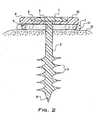
U.S. 4 968 317 . FIGURE 1 depicts a side perspective view of an embodiment of the fastener of the present invention.FIGURE 2 depicts a partial cross sectional view of an embodiment of the fastener of the present invention being used to attach soft tissue to bone.FIGURE 3 depicts an embodiment of the upper side of the washer of the present invention.FIGURE 4 depicts an embodiment of the lower side of the washer of the present invention.FIGURE 5 depicts an embodiment of the fastener of the present invention during the manufacturing process, before the head of the screw has been formed.- With reference to
FIG. 1 , it can be seen that the surgical fastener of the present invention comprises a screw and a washer combination. The screw has a head 1, ashank 2, and at least onethread 3. Theshank 2 of the screw passes through thehole 5 in thewasher 4. - One of the major difficulties faced in repairing injuries to the rotator cuff is fashioning a repair that will withstand the strong forces that are exerted on the tendons of the rotator cuff during and after the healing process. Previous screws have not been particularly successful in treating injuries to the rotator cuff because the tendons of the rotator cuff would easily pull the screws out of the humerus into which they were inserted. In order to withstand these forces, the screw of the present invention has been specially configured to have relatively
tall threads 3. According to the present invention, at least a portion of thethreads 3 have a height, "H", of at least 1.5 mm. These prominent threads provide the screw with greater stability once inserted into bone and allow the screw to attain higher pull out strengths in cancellous bone, such as the bone of the humeral head. - The
threads 3 may take many different shapes. In a preferred embodiment of the present invention, the screw of the invention is self tapping. This simplifies the insertion procedure in softer bone and reduces the length of the repair operation. - Also in a preferred embodiment of the present invention, the tip 8 of the screw has a trocar, fluted, or pyramidal shape. This promotes the easy insertion of the screw into the bone. It also allows the screws to cut easily through the tendon that is being affixed to the bone, without causing unnecessary tearing or twisting of the tendon during the insertion of the screw.
- The large surface area of the
washer 4 effects greater fixation of the tendon to the bone distributed over a larger portion of the tendon. This reduces the risk that the tendon will tear from the screw, causing a failure of the repair. It also reduces the risk that the tendon will separate from the humeral head, causing instability in the shoulder joint. It also creates a broader surface area for tendon to bone healing and vascular ingrown. In a preferred embodiment of the present invention, thelower surface 9 of thewasher 4 has protrusions such asspikes 7, which grip the tendon, firmly affixing it to the bone and preventing unwanted slippage of the tendon during the healing process. As seen inFIG. 2 , in yet another preferred embodiment of the present invention, thespikes 7 are long enough so that the flatlower surface 9 of thewasher 4 is not pressed severely against thetendon 11 being repaired. In some instances, at least portions of the flatlower surface 9 of the washer will not contact thetendon 11. This allows good vascularization of thetenden 11 under repair and reduces the risk of tissue necrosis. Even though thelower surface 9 of thewasher 4 does not compress thetendon 11 under repair severely enough to impair the vascularity of thetendon 11, thespikes 7 hold thetendon 11 firmly in place during the healing process. Thespikes 7 are preferably from 0.6 to 3 mm in length. Thespikes 7 may, but need hot, contact thebone 12. The optimal size and shape of thespikes 7 will depend upon the specific repair to be done in an individual case and will, therefore, vary. - In another preferred embodiment of the present invention, the
upper surface 10 of thewasher 4 contains an indentation or recess 6. This recess 6 may be deep enough to receive the entire head I of the screw. Thus, when the screw is inserted intobone 12, the head 1 of the screw is located mainly or entirely within the recess 6 of thewasher 4. This reduces the profile of the device of the present invention when inserted, thereby reducing the risk of irritation or damage to the surrounding tissues. - The cross section of the
washer 4 may have various shapes, including those with rounded edges, in order to reduce the profile of the inserted device and further reduce the risk of irritation or damage to the surrounding tissues. Similarly, the cross section of the head 1, may have different shapes and sizes, depending upon the particular application for which the fastener is being used. - The device is made of an at least partially bioabsorbable material, such as polylactides, polyglycolides, and copolymers thereof, It should be understood, however, that the present invention may be made from a variety of bioabsorbable materials, a partial list of which is included in
U.S. 4 968 317 . According to the present invention, thewasher 4 is made of a material that bioabsorbs faster than the material from which the screw is constructed. This reduces the risk that the screw will degrade first, allowing the washer to separate from the tendon or bone and cause irritation or damage to surrounding tissues. Preferably, thewasher 4 will be constructed of a material that will retain much of its strength for 4-6 months. This allows enough time for the tendon to heal properly before the washer begins to substantially degrade. The use of bioabsorbable materials reduces the risks related to the use of permanent implants, including irritation, rejection, and the possibility of a second procedure to remove the implant. Further, bioabsorbable implants cause less interference with postoperative MRIs and X-rays, than do metallic implants. - In another preferred embodiment of the present invention, the device is constructed of bioabsorbable material that has been oriented and fibrillated. Procedures for orienting and fibrillating polymers to increase their strength are known in the art and are described, for instance, in
US 4 968 317washer 4 is made from a material that has been biaxially oriented. Such orientation increases the strength of the device, allowing for more secure fixation of tendon to bone. - In another embodiment of the present invention, the bioabsorbable material from which the device is constructed may also contain other elements, such as medication, growth hormones, or other biomaterials that promote growth and healing of tissue.
- The screw and washer combination of the present invention greatly reduces the amount of time needed to effect a repair of the rotator cuff. Further, it is far easier to use than previously developed suturing techniques. This is particularly true when the present invention is used arthroscopically. Complicated and intricate knot tying is replaced with simply inserting the screw through the
tendon 11 and into thebone 12. Depending upon the strength and hardness of thebone 12, a hole may have to be drilled into thebone 12 prior to inserting the screw, or the screw may be self tapping if thebone 12 is relatively soft. As the screw is inserted, thewasher 4 holds thetendon 11 against thebone 12. While the screw is being screwed into thebone 12, thewasher 4 may rotate around theshank 2 of the screw. Thus, once thewasher 4 contacts thetendon 11, it stays in place relative to thetendon 11, while the screw continues to be screwed into thebone 12. This ensures that thetendon 11 does not get twisted or unnecessarily damaged during the insertion of the screw. Although the present invention is particularly useful for arthroscopic surgical procedures, it may also be used in open procedures as well. - Due to the relatively
tall threads 3 on the screw, and the relativelysmall hole 5 in thewasher 4, thewasher 4 cannot be removed from the screw without damaging either the screw or thewasher 4. This ensures that thewasher 4 will not be inadvertently separated from the screw before or during the insertion procedure. This also simplifies the operation because the surgeon or his assistants do not have to place the washer on the screw before the operation, possibly increasing the risk of contamination of the sterile implant. - In order to achieve this result, the screw and the
washer 4 are manufactured together. Thus, thewasher 4 of the present invention is placed onto theshank 2 of the screw before the head I of the screw is formed. This is illustrated inFIG. 5 . Theshank 2 andthreads 3 of the screw are formed through techniques known in the art. The head 1, however, is missing from the screw. At this point, the fully formedwasher 4 is placed over theshank 2 of the screw. Thewasher 4 is also formed using techniques known in the art. These could include techniques such as extrusion, injection molding, and machining. Once thewasher 4 is placed around theshank 4 of the screw, the head 1 of the screw is formed from the material at the top of theshank 2. This forming step could be achieved, for instance by machining the top of theshank 2. Once the head 1 of the screw is formed, thewasher 4 cannot be easily removed from the screw without damaging either the screw or thewasher 4. - After the description above of the present invention and certain specific embodiments thereof, it will be readily apparent to those skilled in the art that many variations and modifications may be made to the present invention without departing from the scope of the invention as defined in the claims. The following example is intended to be illustrative only, and does not form part of the invention.
- Pull out strength tests were performed on a fastener of the present invention. The tests were performed on the tibia of a cadaverous pig. The meniscus was scraped away from the cartilage surface, and a 3.2 mm diameter hole was drilled through this surface. Subsequently, a shallower 9 mm diameter hole was drilled though the compact surface bone layer. The deep 3.2 mm hole was tapped. A screw and washer, the screw having threads with an outer diameter of about 6.8 mm and an inner diameter of about 3.7 mm, and both being constructed from poly-L-lactide (PLLA), were inserted into the bone with a driver tool having a square tip corresponding to the slot on the head of the screw. The head of the screw was left just above the cartilage surface. A suture was attached to the shank of the screw, and the screw was pulled out of the bone. The force required to remove the screw was measured. Over a series of ten trials, the screw withstood a pull out force of 150 to 260 N.
Claims (16)
- Surgical fastener, comprising:- a screw comprising a distal end, a proximal end having a head (1) having a first diameter and a height, a shank (2) having a second diameter and connected to the head (1), and at least one thread (3) having an outer diameter and an inner diameter, wherein at least a portion of the thread (3) has a height (H) of at least 1.5 mm,
and- an annular washer (4) having a proximal surface (10), a distal surface (9) and an opening (5) therethrough, the proximal surface (10) facing the head (1) of the screw,wherein- the shank (2) of the screw passes through the opening (5) in the washer (4), and- the opening (5) has a third diameter that is larger than the second diameter of the shank (2), smaller than the first diameter of the head (1) and smaller than the outer diameter of the thread (3),characterized in that- the screw and the washer (4) are both at least partially bioabsorbable,
and- the washer (4) is made of a material that degrades faster in vivo than the material from which the screw is made. - Fastener according to claim 1, wherein the at least partially bioabsorbable material is oriented or fibrillated.
- Fastener according to claim 2, wherein the washer (4) comprises an at least partially bioabsorbable material that is biaxially oriented or fibrillated.
- Fastener according to any of claims 1 to 3, wherein the washer (4) further comprises a plurality of protrusions (7) protruding from the distal surface (9) of the washer (4).
- Fastener according to claim 4, wherein at least one of the protrusions (7) is at least 0.6 mm in height.
- Fastener according to any of claims 1 to 5, wherein the proximal surface (10) of the washer (4) contains an indentation (6) configured to removably receive at least a portion of the head (1) of the screw.
- Fastener according to claim 6, wherein the indentation (6) has a depth that is greater or equal to the height of the head (1) of the screw.
- Fastener according to any of claims 1 to 7, wherein the distal end of the screw has a trocar tip (8).
- Method for manufacturing a surgical fastener, which comprises a screw comprising a distal end, a proximal end having a head (1), a head having a height, a shank (2) connected to the head (1) and at least one thread (3),
comprising the following steps:- providing a screw comprising a distal end and a proximal end, a head having a height, a shank (2) having a second diameter and at least one thread (3) having an outer diameter and an inner diameter,- providing an annular washer (4) having a proximal surface (10), a distal surface (9) and an opening (5) therethrough, the opening (5) having a third diameter that is larger than the second diameter of the shank (2) and smaller than the outer diameter of the thread (3),
and- inserting the shank (2) through the washer (4) so that the distal surface (9) of the washer (4) faces the thread (3) and a portion of the shank (2) protrudes above the proximal surface (10) of the washer (4),wherein- when inserting the shank (2) through the washer (4), the washer (4) is placed onto the shank (2) of the screw before the head (1) of the screw is formed,- thereafter, the head (1) of the screw is formed from a portion of the shank (2) above the proximal surface (10) of the washer (4), the head (1) of the screw having a first diameter that is larger than the third diameter of the opening (5),- the screw and the washer (4) used are both at least partially bioabsorbable,
and- the washer (4) used is made of a material that degrades faster in vivo than the material from which the screw is made. - Method according to claim 9, wherein the screw or the washer (4) used is oriented or fibrillated.
- Method according to claim 10, wherein the washer (4) used comprises an at least partially bioabsorbable material that is biaxially oriented or fibrillated.
- Method according to any of claims 9 to 11, wherein the washer (4) used further comprises a plurality of protrusions (7) protruding from the distal surface of the washer (4).
- Method according to claim 12, wherein at least one of the protrusions (7) is at least 0.6 mm in height.
- Method according to any of claims 9 to 13, wherein the proximal surface (10) of the washer (4) further comprises an indentation (6) configured to removably receive at least a portion of the head (1) of the screw.
- Method according to claim 14, wherein the indentation (6) has a depth that is greater or equal to the height of the head (1) of the screw.
- Method according to any of claims 9 to 15, wherein the distal end of the screw used has a trocar tip (8).
Applications Claiming Priority (3)
| Application Number | Priority Date | Filing Date | Title |
|---|---|---|---|
| US163946 | 1993-12-08 | ||
| US09/163,946US6248108B1 (en) | 1998-09-30 | 1998-09-30 | Bioabsorbable surgical screw and washer system |
| PCT/US1999/022700WO2000018309A1 (en) | 1998-09-30 | 1999-09-29 | Bioabsorbable surgical screw and washer system |
Publications (3)
| Publication Number | Publication Date |
|---|---|
| EP1131007A1 EP1131007A1 (en) | 2001-09-12 |
| EP1131007A4 EP1131007A4 (en) | 2008-07-02 |
| EP1131007B1true EP1131007B1 (en) | 2010-05-26 |
Family
ID=22592315
Family Applications (1)
| Application Number | Title | Priority Date | Filing Date |
|---|---|---|---|
| EP99948510AExpired - LifetimeEP1131007B1 (en) | 1998-09-30 | 1999-09-29 | Bioabsorbable surgical screw and washer system |
Country Status (8)
| Country | Link |
|---|---|
| US (2) | US6248108B1 (en) |
| EP (1) | EP1131007B1 (en) |
| JP (1) | JP2002525157A (en) |
| AT (1) | ATE468821T1 (en) |
| AU (1) | AU6167499A (en) |
| DE (1) | DE69942421D1 (en) |
| ES (1) | ES2344620T3 (en) |
| WO (1) | WO2000018309A1 (en) |
Families Citing this family (122)
| Publication number | Priority date | Publication date | Assignee | Title |
|---|---|---|---|---|
| US7094239B1 (en)* | 1999-05-05 | 2006-08-22 | Sdgi Holdings, Inc. | Screws of cortical bone and method of manufacture thereof |
| US6319252B1 (en) | 1999-07-23 | 2001-11-20 | Mcdevitt Dennis | System and method for attaching soft tissue to bone |
| US6527794B1 (en)* | 1999-08-10 | 2003-03-04 | Ethicon, Inc. | Self-locking suture anchor |
| GB0026024D0 (en)* | 2000-10-25 | 2000-12-13 | Xiros Plc | Fixation device for use in surgery |
| US6733506B1 (en)* | 2000-11-16 | 2004-05-11 | Ethicon, Inc. | Apparatus and method for attaching soft tissue to bone |
| WO2003049628A1 (en)* | 2000-11-24 | 2003-06-19 | David Lee Kane | Collapsed deployable soft tissue anchor for repairing soft tissue to bone |
| US6511481B2 (en)* | 2001-03-30 | 2003-01-28 | Triage Medical, Inc. | Method and apparatus for fixation of proximal femoral fractures |
| US6887243B2 (en) | 2001-03-30 | 2005-05-03 | Triage Medical, Inc. | Method and apparatus for bone fixation with secondary compression |
| US6866666B1 (en) | 2001-06-28 | 2005-03-15 | Medicinelodge, Inc. | System and method for attaching soft tissue to bone |
| GB0116341D0 (en)* | 2001-07-04 | 2001-08-29 | Smith & Nephew | Biodegradable polymer systems |
| US20030105465A1 (en)* | 2001-11-13 | 2003-06-05 | Reinhold Schmieding | Implant screw and washer assembly and method of fixation |
| GB0202233D0 (en)* | 2002-01-31 | 2002-03-20 | Smith & Nephew | Bioresorbable polymers |
| US20040230194A1 (en)* | 2002-06-12 | 2004-11-18 | Urbanski Mark G. | Device and method for attaching soft tissue to bone |
| US6793678B2 (en) | 2002-06-27 | 2004-09-21 | Depuy Acromed, Inc. | Prosthetic intervertebral motion disc having dampening |
| JP4988203B2 (en)* | 2002-07-19 | 2012-08-01 | インターヴェンショナル スパイン、インコーポレイテッド | Spinal fixation method and spinal fixation device |
| US7070601B2 (en)* | 2003-01-16 | 2006-07-04 | Triage Medical, Inc. | Locking plate for bone anchors |
| EP1596765A2 (en)* | 2003-02-10 | 2005-11-23 | Smith & Nephew, Inc. | Resorbable devices |
| US7670362B2 (en) | 2003-06-13 | 2010-03-02 | Tyco Healthcare Group Lp | Multiple member interconnect for surgical instrument and absorbable screw fastener |
| US7255700B2 (en)* | 2003-06-18 | 2007-08-14 | Biomet Sports Medicine, Inc. | Device and method of fastening a graft to a bone |
| US8105367B2 (en) | 2003-09-29 | 2012-01-31 | Smith & Nephew, Inc. | Bone plate and bone plate assemblies including polyaxial fasteners |
| US7141354B2 (en)* | 2003-09-30 | 2006-11-28 | Dai Nippon Printing Co., Ltd. | Photo radical generator, photo sensitive resin composition and article |
| CA2548469A1 (en)* | 2003-12-01 | 2005-06-16 | Smith & Nephew, Inc. | Humeral nail with insert for fixing a screw |
| GB0329654D0 (en) | 2003-12-23 | 2004-01-28 | Smith & Nephew | Tunable segmented polyacetal |
| US20100191292A1 (en)* | 2004-02-17 | 2010-07-29 | Demeo Joseph | Oriented polymer implantable device and process for making same |
| US7378144B2 (en)* | 2004-02-17 | 2008-05-27 | Kensey Nash Corporation | Oriented polymer implantable device and process for making same |
| US7615069B2 (en)* | 2004-04-08 | 2009-11-10 | Globus Medical, Inc. | Load distribution crown |
| US9474560B2 (en) | 2004-04-08 | 2016-10-25 | Globus Medical, Inc | Load distribution crown |
| US9504583B2 (en)* | 2004-06-10 | 2016-11-29 | Spinal Elements, Inc. | Implant and method for facet immobilization |
| US20060089647A1 (en)* | 2004-08-20 | 2006-04-27 | Culbert Brad S | Method and apparatus for delivering an agent |
| US7648523B2 (en) | 2004-12-08 | 2010-01-19 | Interventional Spine, Inc. | Method and apparatus for spinal stabilization |
| US7857832B2 (en)* | 2004-12-08 | 2010-12-28 | Interventional Spine, Inc. | Method and apparatus for spinal stabilization |
| US20060149266A1 (en)* | 2004-12-10 | 2006-07-06 | New York Society For The Ruptured And Crippled Maintaining The Hospital For Special Surgery | Anchor for screw fixation of soft tissue to bone |
| US7150929B2 (en)* | 2004-12-29 | 2006-12-19 | Utc Fuel Cells, Llc | Fuel cell coolers with inverse flow and condensation zone |
| US7410488B2 (en) | 2005-02-18 | 2008-08-12 | Smith & Nephew, Inc. | Hindfoot nail |
| US8382807B2 (en) | 2005-07-25 | 2013-02-26 | Smith & Nephew, Inc. | Systems and methods for using polyaxial plates |
| CA2616798C (en) | 2005-07-25 | 2014-01-28 | Smith & Nephew, Inc. | Systems and methods for using polyaxial plates |
| WO2007014279A2 (en)* | 2005-07-25 | 2007-02-01 | Smith & Nephew, Inc. | Polyaxial fastener systems and methods |
| WO2007020432A2 (en)* | 2005-08-18 | 2007-02-22 | Smith & Nephew, Plc | High strength devices and composites |
| US8043347B2 (en) | 2005-12-29 | 2011-10-25 | Industrial Technology Research Institute | Device and method for fixing soft tissue |
| US20070154514A1 (en)* | 2005-12-30 | 2007-07-05 | Demakas John J | Therapeutic Structures |
| US9849216B2 (en) | 2006-03-03 | 2017-12-26 | Smith & Nephew, Inc. | Systems and methods for delivering a medicament |
| US20070244565A1 (en)* | 2006-04-17 | 2007-10-18 | Stchur Robert P | Prosthetic humeral device and method |
| FR2900561B1 (en)* | 2006-05-04 | 2008-12-05 | Tornier Sas | DEVICE FOR FIXING SUTURE WIRES |
| ATE505145T1 (en)* | 2006-06-07 | 2011-04-15 | Disc Motion Technologies Inc | PEDICLE SCREW |
| US9788825B2 (en) | 2006-08-04 | 2017-10-17 | Depuy Mitek, Llc | Suture anchor with relief mechanism |
| US9750492B2 (en) | 2006-08-04 | 2017-09-05 | Depuy Mitek, Llc | Suture anchor system with tension relief mechanism |
| US8361130B2 (en)* | 2006-10-06 | 2013-01-29 | Depuy Spine, Inc. | Bone screw fixation |
| US8722783B2 (en) | 2006-11-30 | 2014-05-13 | Smith & Nephew, Inc. | Fiber reinforced composite material |
| WO2008070863A2 (en) | 2006-12-07 | 2008-06-12 | Interventional Spine, Inc. | Intervertebral implant |
| US8608751B2 (en)* | 2006-12-15 | 2013-12-17 | Zimmer, Inc. | Assembly system for orthopedic components |
| US8133261B2 (en) | 2007-02-26 | 2012-03-13 | Depuy Spine, Inc. | Intra-facet fixation device and method of use |
| US8702762B2 (en) | 2007-03-27 | 2014-04-22 | Depuy Spine, Inc. | Passive screw locking mechanism |
| US8043334B2 (en)* | 2007-04-13 | 2011-10-25 | Depuy Spine, Inc. | Articulating facet fusion screw |
| US8197513B2 (en) | 2007-04-13 | 2012-06-12 | Depuy Spine, Inc. | Facet fixation and fusion wedge and method of use |
| US8894685B2 (en) | 2007-04-13 | 2014-11-25 | DePuy Synthes Products, LLC | Facet fixation and fusion screw and washer assembly and method of use |
| EP2142353A1 (en) | 2007-04-18 | 2010-01-13 | Smith & Nephew PLC | Expansion moulding of shape memory polymers |
| EP2150288B1 (en) | 2007-04-19 | 2011-04-13 | Smith & Nephew, Inc. | Graft fixation |
| US9000066B2 (en) | 2007-04-19 | 2015-04-07 | Smith & Nephew, Inc. | Multi-modal shape memory polymers |
| US8177849B2 (en) | 2007-05-07 | 2012-05-15 | Zimmer, Inc. | Methods and apparatuses for attaching tissue to orthopaedic implants |
| US8900307B2 (en) | 2007-06-26 | 2014-12-02 | DePuy Synthes Products, LLC | Highly lordosed fusion cage |
| EP2237748B1 (en) | 2008-01-17 | 2012-09-05 | Synthes GmbH | An expandable intervertebral implant |
| US20090192529A1 (en)* | 2008-01-22 | 2009-07-30 | Michael Kaveney | Soft tissue reattachment mechanism |
| US8936641B2 (en) | 2008-04-05 | 2015-01-20 | DePuy Synthes Products, LLC | Expandable intervertebral implant |
| EP2410929B1 (en)* | 2009-03-24 | 2019-06-26 | Stabiliz Orthopedics, LLC | Orthopedic fixation device with bioresorbable layer |
| US9526620B2 (en) | 2009-03-30 | 2016-12-27 | DePuy Synthes Products, Inc. | Zero profile spinal fusion cage |
| US8529609B2 (en)* | 2009-12-01 | 2013-09-10 | Osteomed Llc | Polyaxial facet fixation screw system |
| US8998966B2 (en) | 2009-12-01 | 2015-04-07 | Osteomed, Llc | Polyaxial facet fixation screw system with fixation augmentation |
| US9078707B2 (en) | 2009-12-01 | 2015-07-14 | Osteomed Llc | Polyaxial facet fixation screw system with cannula inserter |
| US9393129B2 (en) | 2009-12-10 | 2016-07-19 | DePuy Synthes Products, Inc. | Bellows-like expandable interbody fusion cage |
| US8683895B2 (en)* | 2010-02-23 | 2014-04-01 | Kensey Nash Corporation | Single revolution snap action drive for surgical fasteners |
| US20140243912A1 (en)* | 2010-05-28 | 2014-08-28 | Jean-Pierre Mobasser | Awl-tipped pedicle screw and method of implanting same |
| US8979860B2 (en) | 2010-06-24 | 2015-03-17 | DePuy Synthes Products. LLC | Enhanced cage insertion device |
| US9907560B2 (en) | 2010-06-24 | 2018-03-06 | DePuy Synthes Products, Inc. | Flexible vertebral body shavers |
| US8623091B2 (en) | 2010-06-29 | 2014-01-07 | DePuy Synthes Products, LLC | Distractible intervertebral implant |
| US9089372B2 (en) | 2010-07-12 | 2015-07-28 | DePuy Synthes Products, Inc. | Pedicular facet fusion screw with plate |
| US9402732B2 (en) | 2010-10-11 | 2016-08-02 | DePuy Synthes Products, Inc. | Expandable interspinous process spacer implant |
| AU2012271441B2 (en) | 2011-06-15 | 2017-02-02 | Smith & Nephew, Inc. | Variable angle locking implant |
| US9119678B2 (en) | 2011-11-01 | 2015-09-01 | Synergy Disc Replacement Inc. | Facet fixation systems |
| US9414865B2 (en) | 2011-11-01 | 2016-08-16 | Synergy Disc Replacement Inc. | Joint and bone fixation |
| FR2983396B1 (en)* | 2011-12-05 | 2014-06-27 | Fournitures Hospitalieres Ind | OSTEOSYNTHESIS DEVICE, IN PARTICULAR FOR CORRECTING A DETECTION OF A TOE AND ANCILLARY FOR THE PLACEMENT OF THE SAME |
| US9151316B2 (en) | 2012-07-25 | 2015-10-06 | Alan R. Smith | Fastener with unidirectional latch |
| EP2877127B1 (en) | 2012-07-26 | 2019-08-21 | Synthes GmbH | Expandable implant |
| US20140067069A1 (en) | 2012-08-30 | 2014-03-06 | Interventional Spine, Inc. | Artificial disc |
| US9717601B2 (en) | 2013-02-28 | 2017-08-01 | DePuy Synthes Products, Inc. | Expandable intervertebral implant, system, kit and method |
| US9522070B2 (en) | 2013-03-07 | 2016-12-20 | Interventional Spine, Inc. | Intervertebral implant |
| US10456182B2 (en) | 2013-03-13 | 2019-10-29 | Paragon 28, Inc. | Force distribution implant, assembly and kit |
| AU2014228420B2 (en)* | 2013-03-15 | 2018-11-08 | Smith & Nephew, Inc. | Surgical fastening |
| US9522028B2 (en) | 2013-07-03 | 2016-12-20 | Interventional Spine, Inc. | Method and apparatus for sacroiliac joint fixation |
| US9433493B2 (en)* | 2013-11-04 | 2016-09-06 | Biomet Sports Medicine, Llc | Tissue contacting member |
| US9615830B2 (en) | 2013-11-08 | 2017-04-11 | C.R. Bard, Inc. | Surgical fastener |
| US9445814B2 (en)* | 2013-11-08 | 2016-09-20 | C.R. Bard, Inc. | Surgical fastener |
| US9675353B2 (en) | 2013-11-08 | 2017-06-13 | C.R. Bard, Inc. | Surgical fasteners and associated deployment devices |
| US10368870B2 (en) | 2013-11-08 | 2019-08-06 | C.R. Bard, Inc. | Surgical fastener |
| ES2558755B1 (en)* | 2014-08-07 | 2016-12-15 | Mba Incorporado, S.L. | Suture cable locking system in bone fixation devices |
| CN114983502A (en) | 2014-12-03 | 2022-09-02 | 正畸医学公司 | Bone implant with tethered bands |
| US11426290B2 (en) | 2015-03-06 | 2022-08-30 | DePuy Synthes Products, Inc. | Expandable intervertebral implant, system, kit and method |
| US9913727B2 (en) | 2015-07-02 | 2018-03-13 | Medos International Sarl | Expandable implant |
| GB2557840B (en) | 2015-09-18 | 2021-07-21 | Smith & Nephew Inc | Bone plate |
| CA3000193C (en) | 2015-09-29 | 2023-09-05 | Robert J. Leichti | Washer with shear tube |
| US10307153B2 (en) | 2016-02-22 | 2019-06-04 | Michael William Nordmeyer | Systems, devices and methods for affixing soft tissue to bone |
| EP3474784A2 (en) | 2016-06-28 | 2019-05-01 | Eit Emerging Implant Technologies GmbH | Expandable and angularly adjustable intervertebral cages with articulating joint |
| US11510788B2 (en) | 2016-06-28 | 2022-11-29 | Eit Emerging Implant Technologies Gmbh | Expandable, angularly adjustable intervertebral cages |
| US11045305B2 (en) | 2016-08-26 | 2021-06-29 | Paragon 28, Inc. | Soft tissue retention devices, instrumentation and related methods |
| ES2817794T3 (en) | 2016-08-26 | 2021-04-08 | Paragon 28 Inc | Tendon retention device |
| US10537436B2 (en) | 2016-11-01 | 2020-01-21 | DePuy Synthes Products, Inc. | Curved expandable cage |
| US10888433B2 (en) | 2016-12-14 | 2021-01-12 | DePuy Synthes Products, Inc. | Intervertebral implant inserter and related methods |
| US10251744B2 (en) | 2017-01-27 | 2019-04-09 | Onkos Surgical, Inc. | Soft tissue fixation device |
| US10398563B2 (en) | 2017-05-08 | 2019-09-03 | Medos International Sarl | Expandable cage |
| US11344424B2 (en) | 2017-06-14 | 2022-05-31 | Medos International Sarl | Expandable intervertebral implant and related methods |
| US10940016B2 (en) | 2017-07-05 | 2021-03-09 | Medos International Sarl | Expandable intervertebral fusion cage |
| WO2019113292A1 (en)* | 2017-12-07 | 2019-06-13 | Rotation Medical, Inc. | Medical implant delivery system and related methods |
| CA3099263C (en) | 2018-05-04 | 2022-05-10 | Paragon 28, Inc. | Soft tissue retention device, instrumentation and related methods |
| US11000360B2 (en) | 2018-09-14 | 2021-05-11 | Onkos Surgical, Inc. | Systems and methods for attaching soft tissue to an implant |
| US11446156B2 (en) | 2018-10-25 | 2022-09-20 | Medos International Sarl | Expandable intervertebral implant, inserter instrument, and related methods |
| US11857419B2 (en)* | 2019-02-21 | 2024-01-02 | Samaritan Biologics, LLC | Methods and apparatus for facilitating grafting in surgical procedures |
| US11123122B2 (en)* | 2019-02-27 | 2021-09-21 | Warsaw Orthopedic, Inc. | Anatomy buttressing adaptor |
| US11426286B2 (en) | 2020-03-06 | 2022-08-30 | Eit Emerging Implant Technologies Gmbh | Expandable intervertebral implant |
| DE102021112214A1 (en)* | 2020-05-14 | 2021-11-18 | Inovedis Gmbh | Tendon fixation plate |
| US11850160B2 (en) | 2021-03-26 | 2023-12-26 | Medos International Sarl | Expandable lordotic intervertebral fusion cage |
| US11752009B2 (en) | 2021-04-06 | 2023-09-12 | Medos International Sarl | Expandable intervertebral fusion cage |
| US12168992B2 (en) | 2021-08-05 | 2024-12-17 | The Hillman Group, Inc. | Hardware assembly |
| US12090064B2 (en) | 2022-03-01 | 2024-09-17 | Medos International Sarl | Stabilization members for expandable intervertebral implants, and related systems and methods |
Family Cites Families (9)
| Publication number | Priority date | Publication date | Assignee | Title |
|---|---|---|---|---|
| FI81498C (en) | 1987-01-13 | 1990-11-12 | Biocon Oy | SURGICAL MATERIAL OCH INSTRUMENT. |
| US4988351A (en)* | 1989-01-06 | 1991-01-29 | Concept, Inc. | Washer for use with cancellous screw for attaching soft tissue to bone |
| US5720753A (en)* | 1991-03-22 | 1998-02-24 | United States Surgical Corporation | Orthopedic fastener |
| AU672596B2 (en)* | 1992-02-14 | 1996-10-10 | Smith & Nephew, Inc. | Polymeric screws and coatings for surgical uses |
| ES2185651T3 (en)* | 1993-06-04 | 2003-05-01 | Smith & Nephew Inc | SURGICAL SCREW AND WASHER. |
| FR2718944B1 (en)* | 1994-04-20 | 1996-08-30 | Pierre Roussouly | Orthopedic anchoring stabilization device. |
| WO1996041574A2 (en)* | 1995-06-07 | 1996-12-27 | Innovasive Devices, Inc. | Surgical system and method for the reattachment of soft tissue to bone |
| CA2158890C (en)* | 1995-09-22 | 2002-01-22 | John Runciman | Spherical washer for use with a bone screw |
| FR2758975B1 (en)* | 1997-02-05 | 1999-04-30 | Ethnor | MATERIAL FOR FIXING A TENDON OF MUSCLE ON A BONE |
- 1998
- 1998-09-30USUS09/163,946patent/US6248108B1/ennot_activeExpired - Lifetime
- 1999
- 1999-09-29AUAU61674/99Apatent/AU6167499A/ennot_activeAbandoned
- 1999-09-29WOPCT/US1999/022700patent/WO2000018309A1/enactiveApplication Filing
- 1999-09-29JPJP2000571832Apatent/JP2002525157A/enactivePending
- 1999-09-29EPEP99948510Apatent/EP1131007B1/ennot_activeExpired - Lifetime
- 1999-09-29DEDE69942421Tpatent/DE69942421D1/ennot_activeExpired - Lifetime
- 1999-09-29ATAT99948510Tpatent/ATE468821T1/ennot_activeIP Right Cessation
- 1999-09-29ESES99948510Tpatent/ES2344620T3/ennot_activeExpired - Lifetime
- 2001
- 2001-05-14USUS09/853,623patent/US6383187B2/ennot_activeExpired - Lifetime
Also Published As
| Publication number | Publication date |
|---|---|
| JP2002525157A (en) | 2002-08-13 |
| US6248108B1 (en) | 2001-06-19 |
| DE69942421D1 (en) | 2010-07-08 |
| EP1131007A1 (en) | 2001-09-12 |
| WO2000018309A1 (en) | 2000-04-06 |
| EP1131007A4 (en) | 2008-07-02 |
| AU6167499A (en) | 2000-04-17 |
| ATE468821T1 (en) | 2010-06-15 |
| ES2344620T3 (en) | 2010-09-01 |
| US6383187B2 (en) | 2002-05-07 |
| US20010031966A1 (en) | 2001-10-18 |
Similar Documents
| Publication | Publication Date | Title |
|---|---|---|
| EP1131007B1 (en) | Bioabsorbable surgical screw and washer system | |
| US10123793B2 (en) | Method and apparatus for re-attaching the labrum to the acetabulum including the provision and use of a novel suture anchor system | |
| US8968374B2 (en) | Self-tapping biocompatible interference bone screw | |
| EP0734230B1 (en) | Suture anchor device | |
| US6264677B1 (en) | Wedge screw suture anchor | |
| US7226469B2 (en) | Insert molded suture anchor | |
| AU766069B2 (en) | Suture anchor having multiple sutures | |
| USRE36289E (en) | Umbrella shaped suture anchor device with actuating ring member | |
| US5545180A (en) | Umbrella-shaped suture anchor device with actuating ring member | |
| CN100536795C (en) | Suture anchor for placement in a bone hole | |
| US20070225764A1 (en) | Insert molded suture anchor | |
| WO2008063317A1 (en) | Press fit suture anchor and inserter assembly | |
| JP2005270668A (en) | Implantable cross-pin for repairing anterior cruciate ligament | |
| US10426456B2 (en) | Method and apparatus for re-attaching the labrum to the acetabulum, including the provision and use of a novel suture anchor system | |
| EP1234544B1 (en) | Insert molded push-in suture anchor | |
| Fedenia | Optimization of insertion holes and anchor design for cylinder shaped toggle type suture anchors |
Legal Events
| Date | Code | Title | Description |
|---|---|---|---|
| PUAI | Public reference made under article 153(3) epc to a published international application that has entered the european phase | Free format text:ORIGINAL CODE: 0009012 | |
| 17P | Request for examination filed | Effective date:20010502 | |
| AK | Designated contracting states | Kind code of ref document:A1 Designated state(s):AT BE CH CY DE DK ES FI FR GB GR IE IT LI LU MC NL PT SE | |
| RAP1 | Party data changed (applicant data changed or rights of an application transferred) | Owner name:LINVATEC BIOMATERIALS LTD. | |
| A4 | Supplementary search report drawn up and despatched | Effective date:20080529 | |
| 17Q | First examination report despatched | Effective date:20080904 | |
| GRAP | Despatch of communication of intention to grant a patent | Free format text:ORIGINAL CODE: EPIDOSNIGR1 | |
| GRAS | Grant fee paid | Free format text:ORIGINAL CODE: EPIDOSNIGR3 | |
| GRAA | (expected) grant | Free format text:ORIGINAL CODE: 0009210 | |
| AK | Designated contracting states | Kind code of ref document:B1 Designated state(s):AT BE CH CY DE DK ES FI FR GB GR IE IT LI LU MC NL PT SE | |
| REG | Reference to a national code | Ref country code:GB Ref legal event code:FG4D | |
| REG | Reference to a national code | Ref country code:CH Ref legal event code:EP | |
| REG | Reference to a national code | Ref country code:IE Ref legal event code:FG4D | |
| REF | Corresponds to: | Ref document number:69942421 Country of ref document:DE Date of ref document:20100708 Kind code of ref document:P | |
| REG | Reference to a national code | Ref country code:ES Ref legal event code:FG2A Ref document number:2344620 Country of ref document:ES Kind code of ref document:T3 | |
| REG | Reference to a national code | Ref country code:NL Ref legal event code:VDEP Effective date:20100526 | |
| PG25 | Lapsed in a contracting state [announced via postgrant information from national office to epo] | Ref country code:SE Free format text:LAPSE BECAUSE OF FAILURE TO SUBMIT A TRANSLATION OF THE DESCRIPTION OR TO PAY THE FEE WITHIN THE PRESCRIBED TIME-LIMIT Effective date:20100526 | |
| PG25 | Lapsed in a contracting state [announced via postgrant information from national office to epo] | Ref country code:AT Free format text:LAPSE BECAUSE OF FAILURE TO SUBMIT A TRANSLATION OF THE DESCRIPTION OR TO PAY THE FEE WITHIN THE PRESCRIBED TIME-LIMIT Effective date:20100526 | |
| PG25 | Lapsed in a contracting state [announced via postgrant information from national office to epo] | Ref country code:CY Free format text:LAPSE BECAUSE OF NON-PAYMENT OF DUE FEES Effective date:20100526 | |
| PG25 | Lapsed in a contracting state [announced via postgrant information from national office to epo] | Ref country code:PT Free format text:LAPSE BECAUSE OF FAILURE TO SUBMIT A TRANSLATION OF THE DESCRIPTION OR TO PAY THE FEE WITHIN THE PRESCRIBED TIME-LIMIT Effective date:20100927 Ref country code:NL Free format text:LAPSE BECAUSE OF FAILURE TO SUBMIT A TRANSLATION OF THE DESCRIPTION OR TO PAY THE FEE WITHIN THE PRESCRIBED TIME-LIMIT Effective date:20100526 Ref country code:DK Free format text:LAPSE BECAUSE OF FAILURE TO SUBMIT A TRANSLATION OF THE DESCRIPTION OR TO PAY THE FEE WITHIN THE PRESCRIBED TIME-LIMIT Effective date:20100526 | |
| PG25 | Lapsed in a contracting state [announced via postgrant information from national office to epo] | Ref country code:BE Free format text:LAPSE BECAUSE OF FAILURE TO SUBMIT A TRANSLATION OF THE DESCRIPTION OR TO PAY THE FEE WITHIN THE PRESCRIBED TIME-LIMIT Effective date:20100526 | |
| PGFP | Annual fee paid to national office [announced via postgrant information from national office to epo] | Ref country code:BE Payment date:20101012 Year of fee payment:12 | |
| PLBE | No opposition filed within time limit | Free format text:ORIGINAL CODE: 0009261 | |
| STAA | Information on the status of an ep patent application or granted ep patent | Free format text:STATUS: NO OPPOSITION FILED WITHIN TIME LIMIT | |
| PG25 | Lapsed in a contracting state [announced via postgrant information from national office to epo] | Ref country code:MC Free format text:LAPSE BECAUSE OF NON-PAYMENT OF DUE FEES Effective date:20100930 | |
| REG | Reference to a national code | Ref country code:CH Ref legal event code:PL | |
| 26N | No opposition filed | Effective date:20110301 | |
| PG25 | Lapsed in a contracting state [announced via postgrant information from national office to epo] | Ref country code:GR Free format text:LAPSE BECAUSE OF FAILURE TO SUBMIT A TRANSLATION OF THE DESCRIPTION OR TO PAY THE FEE WITHIN THE PRESCRIBED TIME-LIMIT Effective date:20100827 | |
| REG | Reference to a national code | Ref country code:DE Ref legal event code:R097 Ref document number:69942421 Country of ref document:DE Effective date:20110228 | |
| PG25 | Lapsed in a contracting state [announced via postgrant information from national office to epo] | Ref country code:CH Free format text:LAPSE BECAUSE OF NON-PAYMENT OF DUE FEES Effective date:20100930 Ref country code:IE Free format text:LAPSE BECAUSE OF NON-PAYMENT OF DUE FEES Effective date:20100929 Ref country code:LI Free format text:LAPSE BECAUSE OF NON-PAYMENT OF DUE FEES Effective date:20100930 | |
| PG25 | Lapsed in a contracting state [announced via postgrant information from national office to epo] | Ref country code:LU Free format text:LAPSE BECAUSE OF NON-PAYMENT OF DUE FEES Effective date:20100929 | |
| REG | Reference to a national code | Ref country code:FR Ref legal event code:PLFP Year of fee payment:18 | |
| REG | Reference to a national code | Ref country code:FR Ref legal event code:PLFP Year of fee payment:19 | |
| REG | Reference to a national code | Ref country code:FR Ref legal event code:PLFP Year of fee payment:20 | |
| PGFP | Annual fee paid to national office [announced via postgrant information from national office to epo] | Ref country code:DE Payment date:20180927 Year of fee payment:20 Ref country code:IT Payment date:20180920 Year of fee payment:20 Ref country code:FR Payment date:20180925 Year of fee payment:20 | |
| PGFP | Annual fee paid to national office [announced via postgrant information from national office to epo] | Ref country code:FI Payment date:20180927 Year of fee payment:20 Ref country code:GB Payment date:20180927 Year of fee payment:20 | |
| PGFP | Annual fee paid to national office [announced via postgrant information from national office to epo] | Ref country code:ES Payment date:20181001 Year of fee payment:20 | |
| REG | Reference to a national code | Ref country code:DE Ref legal event code:R071 Ref document number:69942421 Country of ref document:DE | |
| REG | Reference to a national code | Ref country code:GB Ref legal event code:PE20 Expiry date:20190928 | |
| PG25 | Lapsed in a contracting state [announced via postgrant information from national office to epo] | Ref country code:GB Free format text:LAPSE BECAUSE OF EXPIRATION OF PROTECTION Effective date:20190928 | |
| REG | Reference to a national code | Ref country code:ES Ref legal event code:FD2A Effective date:20200804 | |
| PG25 | Lapsed in a contracting state [announced via postgrant information from national office to epo] | Ref country code:ES Free format text:LAPSE BECAUSE OF EXPIRATION OF PROTECTION Effective date:20190930 |