EP1130766B1 - Automotive dynamo controller - Google Patents
Automotive dynamo controllerDownload PDFInfo
- Publication number
- EP1130766B1 EP1130766B1EP99943280.0AEP99943280AEP1130766B1EP 1130766 B1EP1130766 B1EP 1130766B1EP 99943280 AEP99943280 AEP 99943280AEP 1130766 B1EP1130766 B1EP 1130766B1
- Authority
- EP
- European Patent Office
- Prior art keywords
- generator
- output
- current
- voltage
- resistor
- Prior art date
- Legal status (The legal status is an assumption and is not a legal conclusion. Google has not performed a legal analysis and makes no representation as to the accuracy of the status listed.)
- Expired - Lifetime
Links
Images

Classifications
- H—ELECTRICITY
- H02—GENERATION; CONVERSION OR DISTRIBUTION OF ELECTRIC POWER
- H02J—CIRCUIT ARRANGEMENTS OR SYSTEMS FOR SUPPLYING OR DISTRIBUTING ELECTRIC POWER; SYSTEMS FOR STORING ELECTRIC ENERGY
- H02J7/00—Circuit arrangements for charging or depolarising batteries or for supplying loads from batteries
- H02J7/14—Circuit arrangements for charging or depolarising batteries or for supplying loads from batteries for charging batteries from dynamo-electric generators driven at varying speed, e.g. on vehicle
- H02J7/16—Regulation of the charging current or voltage by variation of field
- H02J7/18—Regulation of the charging current or voltage by variation of field due to variation of ohmic resistance in field circuit, using resistance switching in or out of circuit step by step
- H—ELECTRICITY
- H02—GENERATION; CONVERSION OR DISTRIBUTION OF ELECTRIC POWER
- H02P—CONTROL OR REGULATION OF ELECTRIC MOTORS, ELECTRIC GENERATORS OR DYNAMO-ELECTRIC CONVERTERS; CONTROLLING TRANSFORMERS, REACTORS OR CHOKE COILS
- H02P9/00—Arrangements for controlling electric generators for the purpose of obtaining a desired output
- H02P9/10—Control effected upon generator excitation circuit to reduce harmful effects of overloads or transients, e.g. sudden application of load, sudden removal of load, sudden change of load
- H02P9/107—Control effected upon generator excitation circuit to reduce harmful effects of overloads or transients, e.g. sudden application of load, sudden removal of load, sudden change of load for limiting effects of overloads
- H—ELECTRICITY
- H02—GENERATION; CONVERSION OR DISTRIBUTION OF ELECTRIC POWER
- H02J—CIRCUIT ARRANGEMENTS OR SYSTEMS FOR SUPPLYING OR DISTRIBUTING ELECTRIC POWER; SYSTEMS FOR STORING ELECTRIC ENERGY
- H02J7/00—Circuit arrangements for charging or depolarising batteries or for supplying loads from batteries
- H02J7/0042—Circuit arrangements for charging or depolarising batteries or for supplying loads from batteries characterised by the mechanical construction
- H—ELECTRICITY
- H02—GENERATION; CONVERSION OR DISTRIBUTION OF ELECTRIC POWER
- H02J—CIRCUIT ARRANGEMENTS OR SYSTEMS FOR SUPPLYING OR DISTRIBUTING ELECTRIC POWER; SYSTEMS FOR STORING ELECTRIC ENERGY
- H02J7/00—Circuit arrangements for charging or depolarising batteries or for supplying loads from batteries
- H02J7/14—Circuit arrangements for charging or depolarising batteries or for supplying loads from batteries for charging batteries from dynamo-electric generators driven at varying speed, e.g. on vehicle
- H02J7/16—Regulation of the charging current or voltage by variation of field
- H02J7/24—Regulation of the charging current or voltage by variation of field using discharge tubes or semiconductor devices
- H02J7/243—Regulation of the charging current or voltage by variation of field using discharge tubes or semiconductor devices with on/off action
- H—ELECTRICITY
- H02—GENERATION; CONVERSION OR DISTRIBUTION OF ELECTRIC POWER
- H02P—CONTROL OR REGULATION OF ELECTRIC MOTORS, ELECTRIC GENERATORS OR DYNAMO-ELECTRIC CONVERTERS; CONTROLLING TRANSFORMERS, REACTORS OR CHOKE COILS
- H02P9/00—Arrangements for controlling electric generators for the purpose of obtaining a desired output
- H02P9/14—Arrangements for controlling electric generators for the purpose of obtaining a desired output by variation of field
- H02P9/26—Arrangements for controlling electric generators for the purpose of obtaining a desired output by variation of field using discharge tubes or semiconductor devices
- H02P9/30—Arrangements for controlling electric generators for the purpose of obtaining a desired output by variation of field using discharge tubes or semiconductor devices using semiconductor devices
- H02P9/305—Arrangements for controlling electric generators for the purpose of obtaining a desired output by variation of field using discharge tubes or semiconductor devices using semiconductor devices controlling voltage
- H—ELECTRICITY
- H01—ELECTRIC ELEMENTS
- H01L—SEMICONDUCTOR DEVICES NOT COVERED BY CLASS H10
- H01L2224/00—Indexing scheme for arrangements for connecting or disconnecting semiconductor or solid-state bodies and methods related thereto as covered by H01L24/00
- H01L2224/01—Means for bonding being attached to, or being formed on, the surface to be connected, e.g. chip-to-package, die-attach, "first-level" interconnects; Manufacturing methods related thereto
- H01L2224/42—Wire connectors; Manufacturing methods related thereto
- H01L2224/47—Structure, shape, material or disposition of the wire connectors after the connecting process
- H01L2224/49—Structure, shape, material or disposition of the wire connectors after the connecting process of a plurality of wire connectors
- H01L2224/491—Disposition
- H01L2224/4912—Layout
- H01L2224/49171—Fan-out arrangements
- H—ELECTRICITY
- H02—GENERATION; CONVERSION OR DISTRIBUTION OF ELECTRIC POWER
- H02J—CIRCUIT ARRANGEMENTS OR SYSTEMS FOR SUPPLYING OR DISTRIBUTING ELECTRIC POWER; SYSTEMS FOR STORING ELECTRIC ENERGY
- H02J2310/00—The network for supplying or distributing electric power characterised by its spatial reach or by the load
- H02J2310/40—The network being an on-board power network, i.e. within a vehicle
- H02J2310/46—The network being an on-board power network, i.e. within a vehicle for ICE-powered road vehicles
Definitions
- the present inventionrelates to an electronic control circuit for controlling generator output, which is accommodated in a vehicle-mounted A.C. generator, and is in the form of a monolithic IC chip on a ceramic substrate.
- a controllerfor an A.C. generator in a vehicle in which discrete components are employed as circuit elements to be mounted onto a wiring board
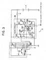
- a controllerwhich has a circuit configuration shown in Fig. 3 .
- This controllerincludes: an A.C. generator 1 having an armature coil 101 for driving an engine and for starting the generating operation of electrical energy, and a field coil 102; a rectifier 2 for taking out an output of generating electrical energy from the armature coil 101 to rectify the output, which is supplied to batteries 4 or to an electrical load (not shown); and a controller 3 having a voltage regulator 3a for detecting the voltage developed across the terminals of the batteries 4 to adjust the output voltage of the A.C. generator 1 on the basis of the voltage thus detected and a field current restricting unit 3b for detecting the field current caused to flow through the field coil 102 to restrict the field current on the basis of the detected current.
- Reference numeral 5indicates a key switch for starting the engine. This key switch 5 is turned ON so that the current flows through the field coil 102 from the batteries 4 to carry out the initial excitation.
- the voltage regulator 3ais configured in such a way as to include: a constant voltage circuit in which an operating resistor 301 and a zener diode 302 are electrically connected in series between the positive electrode of the batteries 4 and the earth through the key switch 5 to fetch a constant voltage A, which is determined on the basis of the breakdown voltage of the Zener diode 302, from a connection point P between the operating resistor 301 and the Zener diode 302; a voltage dividing circuit having voltage dividing resistors 303 and 304, which are electrically connected in series between an output terminal 201 of a positive electrode and an output terminal 202 of a negative electrode of the rectifier 2 to divide the output voltage of the rectifier 2; a first comparator 307 for applying a divided voltage Vd from the voltage dividing circuit to an input terminal (-) of the negative side and for applying a fixed reference voltage V REF1 to an input terminal (+) of the positive side to make H or L the logical level at the output terminal in accordance with the magnitude relationship between the divided voltage
- the field current restricting unit 3bincludes: a voltage dividing circuit having voltage dividing resistors 305 and 306 for dividing a constant voltage A at a predetermined resistance ratio to generate a predetermined reference voltage V REF2 ; a field current detecting resistor 312 connected between an emitter of the output transistor 311 and the earth for converting the field current flowing through the emitter into a voltage V1 to detect the voltage V1 thus obtained; and a second comparator 308 for applying the reference voltage V REF2 to an input terminal (+) of the positive side and for applying the voltage V1 to an input terminal (-) of the negative side to make L the logical level at the output terminal at the time when the voltage V1 has become higher than the reference voltage V REF2 .
- the divided voltage Vd as a criterion of the terminal voltage of the batteries 4rises above the reference voltage V REF1 to provide the over-charging state
- the logical level at the output terminal of the first comparator 307goes to L to turn OFF the output transistor 311 so that the field current to the field coil 102 is shut off, which reduces the output of the electrical energy generation.
- the logical level at the output terminal of the first comparator 307goes to H to turn ON the output transistor 311.
- the current flowing loop consisting of the batteries 4, the field coil 102, the output transistor 311, the field current detecting resistor 312, and the earthis formed so that the field current is caused to flow from the batteries 4 to the field coil 102 to carry out the generation of electrical energy, and also the output of the generation of electrical energy is rectified through the rectifier 2 to be supplied to the batteries 4 which are in turn charged with the fixed voltage 14.5 V for example.
- the output transistor 311is turned repeatedly ON/OFF in accordance with the drop and the rise of the voltage developed across the terminals of the batteries 4 to intermittently control the field current to so that the terminal voltage is maintained at a fixed value.
- the surge current which is generated through the field coil 102 along with the interruption of the field currentis suppressed by the suppression diode 310 to mitigate the influence thereof exerted on the electronic circuit.
- the logical level of the output of the first comparator 307continues to be H, and hence the A.C. generator 1 starts to cause to flow the excessive field current through the output transistor 311 in order to make the divided voltage Vd the reference voltage V REF1 .
- the field currentis caused to flow through the field current detecting resistor 312 to generate the voltage drop of the voltage V1.
- the voltage V1is applied to the negative side input terminal (-) of the second comparator 308.
- the reference voltage V REF2which is used to judge the excessive field current is applied to the positive side input terminal (+) of the second comparator 308.
- the logical level at the output terminal of the second comparator 308goes to L.
- the output at the logical level H of the first comparator 307is absorbed by the output terminal of the second comparator 308, whereby the base current of the output transistor 311 is shut off, and the field current is also shut off to stop the generation of electrical energy to prevent the burning of the A.C. generator.
- the present inventionhas been made in order to solve the above-mentioned problems associated with the prior art, and hence it is therefore an object of the present invention to obtain a controller for an A.C. generator in which the circuit board can be miniaturized and the difficulty of building the circuit board into the body of the A.C. generator is removed, and also a constant of a field current detecting resistance can be readily changed in correspondence with the field current of the A.C. generator.
- the present Inventionis defined in claim 1.
- the high accuracyis required for the output control of an A.C. generator for a vehicle along with the promotion of the electronics of the vehicle control.
- the complexity of the electronic circuits in a controller, and the high density of the circuit configuration in a substrate (board) resulting therefromare unavoidable.
- the respective electronic circuitsexcept for a field current detecting resistor 312, i.e., a voltage regulator 3a and a field current restricting unit 3b are integrated in the form of a monolithic IC chip 321 on a ceramic substrate 320 having a high heat radiating effect.
- a field current detecting resistor 312i.e., a voltage regulator 3a and a field current restricting unit 3b are integrated in the form of a monolithic IC chip 321 on a ceramic substrate 320 having a high heat radiating effect.
- signal I/O terminals 323are formed through the patterning in the periphery of the monolithic IC chip 321.
- the signal I/O terminals 323are electrically connected to the associated electrodes of the monolithic IC chip 321 through bonding wires 322, respectively.
- the field current detecting resistor 312 through which the high current is caused to flow and for which the high accurate resistance value is requiredis constituted by a thick film printed resistor body which is formed on the ceramic substrate utilizing the printing method.
- the resistance value accuracy of the thick film printed resistor bodydepends on the printing accuracy for the resistor body. It is said that in the current technique, the upper limit of the resistance value accuracy is ⁇ 20 %. However, the required accuracy of the resistance value is higher than value.
- the trimming method to adjust the resistance value of the thick film printed resistor bodythere is adopted the method wherein the laser beam is scanned on the resistor body to vaporize and remove a part, suffering the application of the laser beam, of the thick film printed resistor body.
- the electronic circuits except for the field current detecting resistor 312 in the field current restricting unit 3bare formed in the form of a monolithic IC chip on the ceramic substrate 320 respectively, and the field current detecting resistor 312 is formed on the ceramic substrate 320 by utilizing the printing method.
- the circuitsare integrated, whereby the size of the circuit substrate is reduced.
- the resistance value of the field current detecting resistor 312 which is formed on the ceramic substrate 320 by utilizing the printing methodeven after the resistor body has been formed on the ceramic substrate 320 by utilizing the printing method, by utilizing the above-mentioned triming method, can readily be adjusted in accordance with the specification of the field current of the A.C. generator to be used.
- the electronic circuits which constitute the voltage regulator 3a and the field current restricting unit 3b in the control unit 3are integrated into the monolithic IC chip to be formed on the ceramic substrate 320.
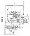
- an electronic circuit of a failure alarm 3c for giving the alarm for the failure of the A.C. generatoris also integrated into the monolithic IC chip to be formed on the ceramic substrate 320, as shown in Fig. 2 .
- the failure alarm 3c in the present embodiment 2includes: a diode 317 for rectifying the A.C. power generation output for one phase which has been fetched out from the armature coil 101 of the A.C. generator 1; a filter 313 for smoothing the power generation output thus rectified; a third comparator 314 for applying the smoothed power generation output (D.C. power generation output) to the positive side input terminal (+) and for applying a reference voltage V REF3 (V REF1 > V REF2 > V REF3 ), which is used to judge the reduction of the power generation output resulting from the failure of the A.C. generator 1 to the negative side input terminal (-); an LED 315 which is electrically connected in series between the terminal through which the constant voltage A is applied and the output terminal of the third comparator 314; and a current restricting resistor 316.
- a diode 317for rectifying the A.C. power generation output for one phase which has been fetched out from the armature coil 101 of the A.C
- the power generation outputsis reduced.
- the power generation output for one phasehas been fetched to be converted into the D.C. output through the diode 317 and the filter 313, it is inputted as the D.C. power generation output to the positive side input terminal (+) of the third comparator.
- the reference voltage V REF3is applied to the negative input terminal (-) of the third comparator.
- the third comparator 314compares the reference voltage V REF3 and the D.C. power generation output with each other.
- the logical level at the output terminalgoes to L.
- the currentis caused to flow through the LED 315 and the current restricting resistor 316 by the constant voltage A, which lights the LED 315 to inform the operator of the failure of the generator whereby the failure of the A.C. generator can be readily recognized.
- an electronic circuit of a control unit which is accommodated inside a vehicle-mounted A.C. generator,and adopted to control an output of the generatoris formed as a monolithic IC chip on a ceramic substrate, whereby the size of the whole apparatus is reduced, and also a resistance value of a field current detecting resistor which has been formed on the ceramic substrate by utilizing the printing method is adjusted in accordance with the specifications of a field current of the A.C. generator.
Landscapes
- Engineering & Computer Science (AREA)
- Power Engineering (AREA)
- Control Of Eletrric Generators (AREA)
Description
- The present invention relates to an electronic control circuit for controlling generator output, which is accommodated in a vehicle-mounted A.C. generator, and is in the form of a monolithic IC chip on a ceramic substrate.
- Heretofore, as a controller, for an A.C. generator in a vehicle in which discrete components are employed as circuit elements to be mounted onto a wiring board, a controller is known which has a circuit configuration shown in
Fig. 3 . This controller includes: an A.C. generator 1 having anarmature coil 101 for driving an engine and for starting the generating operation of electrical energy, and afield coil 102; arectifier 2 for taking out an output of generating electrical energy from thearmature coil 101 to rectify the output, which is supplied to batteries 4 or to an electrical load (not shown); and a controller 3 having a voltage regulator 3a for detecting the voltage developed across the terminals of the batteries 4 to adjust the output voltage of the A.C. generator 1 on the basis of the voltage thus detected and a fieldcurrent restricting unit 3b for detecting the field current caused to flow through thefield coil 102 to restrict the field current on the basis of the detected current. Reference numeral 5 indicates a key switch for starting the engine. Thiskey switch 5 is turned ON so that the current flows through thefield coil 102 from the batteries 4 to carry out the initial excitation.- The voltage regulator 3a is configured in such a way as to include: a constant voltage circuit in which an
operating resistor 301 and azener diode 302 are electrically connected in series between the positive electrode of the batteries 4 and the earth through thekey switch 5 to fetch a constant voltage A, which is determined on the basis of the breakdown voltage of theZener diode 302, from a connection point P between theoperating resistor 301 and theZener diode 302; a voltage dividing circuit havingvoltage dividing resistors output terminal 201 of a positive electrode and anoutput terminal 202 of a negative electrode of therectifier 2 to divide the output voltage of therectifier 2; afirst comparator 307 for applying a divided voltage Vd from the voltage dividing circuit to an input terminal (-) of the negative side and for applying a fixed reference voltage VREF1 to an input terminal (+) of the positive side to make H or L the logical level at the output terminal in accordance with the magnitude relationship between the divided voltage Vd and the reference voltage VREF1;output transistor 311 which is turned ON at the time when the logical level at the output terminal of thefirst comparator 307 has become H to cause the field current to flow through thefield coil 102 from the batteries 4; asuppression diode 310 which is electrically connected in reverse between a positive side line and a collector of theoutput transistor 311 to suppress a surge current which occurs at the time when shutting off the field current; and abase resistor 309 which is electrically connected between the output side of thekey switch 5 and the base of theoutput transistor 311 to restrict a base current which is caused to flow through the base of theoutput transistor 311 at the time when carrying out the initial excitation of thefield coil 102. - The field
current restricting unit 3b includes: a voltage dividing circuit havingvoltage dividing resistors current detecting resistor 312 connected between an emitter of theoutput transistor 311 and the earth for converting the field current flowing through the emitter into a voltage V1 to detect the voltage V1 thus obtained; and asecond comparator 308 for applying the reference voltage VREF2 to an input terminal (+) of the positive side and for applying the voltage V1 to an input terminal (-) of the negative side to make L the logical level at the output terminal at the time when the voltage V1 has become higher than the reference voltage VREF2. - Now, the description hereinbelow will be given with respect to the outline of the operation in the conventional controller for an A.C. generator for a vehicle.
- After having started the engine, the divided voltage Vd as a criterion of the terminal voltage of the batteries 4 rises above the reference voltage VREF1 to provide the over-charging state, the logical level at the output terminal of the
first comparator 307 goes to L to turn OFF theoutput transistor 311 so that the field current to thefield coil 102 is shut off, which reduces the output of the electrical energy generation. - When the terminal voltage of the batteries 4 has been reduced and also the divided voltage Vd has become lower than the reference voltage VREF1, the logical level at the output terminal of the
first comparator 307 goes to H to turn ON theoutput transistor 311. As a result, the current flowing loop consisting of the batteries 4, thefield coil 102, theoutput transistor 311, the fieldcurrent detecting resistor 312, and the earth is formed so that the field current is caused to flow from the batteries 4 to thefield coil 102 to carry out the generation of electrical energy, and also the output of the generation of electrical energy is rectified through therectifier 2 to be supplied to the batteries 4 which are in turn charged with the fixed voltage 14.5 V for example. - In this way, the
output transistor 311 is turned repeatedly ON/OFF in accordance with the drop and the rise of the voltage developed across the terminals of the batteries 4 to intermittently control the field current to so that the terminal voltage is maintained at a fixed value. - The surge current which is generated through the
field coil 102 along with the interruption of the field current is suppressed by thesuppression diode 310 to mitigate the influence thereof exerted on the electronic circuit. - However, if the line through which the terminal voltage of the batteries 4 is detected is cut in the voltage regulator 3a so that the divided voltage Vd becomes zero, for example, then the logical level of the output of the
first comparator 307 continues to be H, and hence the A.C. generator 1 starts to cause to flow the excessive field current through theoutput transistor 311 in order to make the divided voltage Vd the reference voltage VREF1. - At this time, the field current is caused to flow through the field
current detecting resistor 312 to generate the voltage drop of the voltage V1. Then, the voltage V1 is applied to the negative side input terminal (-) of thesecond comparator 308. The reference voltage VREF2 which is used to judge the excessive field current is applied to the positive side input terminal (+) of thesecond comparator 308. At the time when the voltage V1 has become higher than the reference voltage VREF2, the logical level at the output terminal of thesecond comparator 308 goes to L. - For this reason, the output at the logical level H of the
first comparator 307 is absorbed by the output terminal of thesecond comparator 308, whereby the base current of theoutput transistor 311 is shut off, and the field current is also shut off to stop the generation of electrical energy to prevent the burning of the A.C. generator. - If the discrete components such as resistors, capacitors and semiconductor devices are mounted onto the printed board as in the method of mounting the electronic apparatus in the conventional controller, then a large mounting area is required and the scale of the whole controller becomes large.
- In addition thereto, since the high accuracy is required for the output control of the vehicle A.C. generator along with the promotion of the electronics for the vehicle control, the complexity and the high density of the electronic circuit in the controller are unavoidable.
- Therefore, in the case where the discrete components are mounted to the printed board to configure such an electronic circuit, there arises the inconvenience that the scale of the whole controller becomes so large as to restrict the miniaturization of the A.C. generator.
- In the light of the foregoing, the present invention has been made in order to solve the above-mentioned problems associated with the prior art, and hence it is therefore an object of the present invention to obtain a controller for an A.C. generator in which the circuit board can be miniaturized and the difficulty of building the circuit board into the body of the A.C. generator is removed, and also a constant of a field current detecting resistance can be readily changed in correspondence with the field current of the A.C. generator.
- The present Invention is defined in claim 1.
Fig. 1 is a diagram showing the construction when a control unit in a controller of an A.C. generator for a vehicle according to an embodiment 1 of the present invention is configured in the form of an integrated circuit;Fig. 2 is a circuit diagram showing a configuration of a controller of an A.C. generator for a vehicle according to anembodiment 2 of the present invention; andFig. 3 is a circuit diagram showing a configuration of a controller of a conventional A.C. generator for a vehicle.- The high accuracy is required for the output control of an A.C. generator for a vehicle along with the promotion of the electronics of the vehicle control. In response to this requirement, the complexity of the electronic circuits in a controller, and the high density of the circuit configuration in a substrate (board) resulting therefrom are unavoidable.
- Now, in the present embodiment, as shown in
Fig. 1 , the respective electronic circuits, except for a fieldcurrent detecting resistor 312, i.e., a voltage regulator 3a and a fieldcurrent restricting unit 3b are integrated in the form of amonolithic IC chip 321 on aceramic substrate 320 having a high heat radiating effect. In theceramic substrate 320, signal I/O terminals 323 are formed through the patterning in the periphery of themonolithic IC chip 321. The signal I/O terminals 323 are electrically connected to the associated electrodes of themonolithic IC chip 321 throughbonding wires 322, respectively. - Now, the field
current detecting resistor 312 through which the high current is caused to flow and for which the high accurate resistance value is required is constituted by a thick film printed resistor body which is formed on the ceramic substrate utilizing the printing method. - The resistance value accuracy of the thick film printed resistor body depends on the printing accuracy for the resistor body. It is said that in the current technique, the upper limit of the resistance value accuracy is ± 20 %. However, the required accuracy of the resistance value is higher than value.
- Therefore, in general, as the trimming method to adjust the resistance value of the thick film printed resistor body, there is adopted the method wherein the laser beam is scanned on the resistor body to vaporize and remove a part, suffering the application of the laser beam, of the thick film printed resistor body.
- As another trimming method, there is the sand blasting method wherein the powder of alumina is sprayed onto the resistor body to shave off a desired amount of resistor body.
- In such a way, in the present embodiment 1, the electronic circuits except for the field
current detecting resistor 312 in the fieldcurrent restricting unit 3b are formed in the form of a monolithic IC chip on theceramic substrate 320 respectively, and the fieldcurrent detecting resistor 312 is formed on theceramic substrate 320 by utilizing the printing method. - As a result, the circuits are integrated, whereby the size of the circuit substrate is reduced. In addition, the resistance value of the field
current detecting resistor 312 which is formed on theceramic substrate 320 by utilizing the printing method, even after the resistor body has been formed on theceramic substrate 320 by utilizing the printing method, by utilizing the above-mentioned triming method, can readily be adjusted in accordance with the specification of the field current of the A.C. generator to be used. - In the above-mentioned embodiment 1, the electronic circuits which constitute the voltage regulator 3a and the field
current restricting unit 3b in the control unit 3 are integrated into the monolithic IC chip to be formed on theceramic substrate 320. However, alternatively, there may also be adopted the configuration in which in addition to the electric circuit of the conventional control unit, an electronic circuit of afailure alarm 3c for giving the alarm for the failure of the A.C. generator is also integrated into the monolithic IC chip to be formed on theceramic substrate 320, as shown inFig. 2 . - The
failure alarm 3c in thepresent embodiment 2 includes: adiode 317 for rectifying the A.C. power generation output for one phase which has been fetched out from thearmature coil 101 of the A.C. generator 1; afilter 313 for smoothing the power generation output thus rectified; athird comparator 314 for applying the smoothed power generation output (D.C. power generation output) to the positive side input terminal (+) and for applying a reference voltage VREF3 (VREF1 > VREF2 > VREF3), which is used to judge the reduction of the power generation output resulting from the failure of the A.C. generator 1 to the negative side input terminal (-); anLED 315 which is electrically connected in series between the terminal through which the constant voltage A is applied and the output terminal of thethird comparator 314; and acurrent restricting resistor 316. - If, as the operation of the
failure alarm 3c, some failure or other occurs in the A.C. generator 1, then the power generation outputs is reduced. After the power generation output for one phase has been fetched to be converted into the D.C. output through thediode 317 and thefilter 313, it is inputted as the D.C. power generation output to the positive side input terminal (+) of the third comparator. The reference voltage VREF3 is applied to the negative input terminal (-) of the third comparator. Thethird comparator 314 compares the reference voltage VREF3 and the D.C. power generation output with each other. At a time point when the D.C. power generation output has become lower than the reference voltage VREF3, the logical level at the output terminal goes to L. As a result, the current is caused to flow through theLED 315 and thecurrent restricting resistor 316 by the constant voltage A, which lights theLED 315 to inform the operator of the failure of the generator whereby the failure of the A.C. generator can be readily recognized. - According to the present invention, an electronic circuit of a control unit which is accommodated inside a vehicle-mounted A.C. generator,and adopted to control an output of the generator is formed as a monolithic IC chip on a ceramic substrate, whereby the size of the whole apparatus is reduced, and also a resistance value of a field current detecting resistor which has been formed on the ceramic substrate by utilizing the printing method is adjusted in accordance with the specifications of a field current of the A.C. generator.
Claims (4)
- A controller for an A.C. generator for a vehicle, comprising:batteries (4) each of which is charged with electric charges on the basis of an output of generation of electrical energy of an A.C. generator having a field coil (102);voltage regulating means (3a) for regulating a current, which is caused to flow through said field coil, on the basis of the detection result of a voltage developed across the terminals of said batteries due to an output voltage of said A.C. generator into a fixed output value of the generation of electrical energy of said A.C. generator;the voltage regulating means (3a) comprising a constant voltage circuit comprising a Zener diode (302) connected between the terminals of the batteries, an output transistor (311) connected in series with a suppression diode (310) and a field current detecting resistor (312) between the battery terminals, the output transistor being arranged to switch current through the field coil (102) to a battery terminal, and the suppression diode being arranged to suppress a surge current when shutting off the field current;
and field current restricting means (3b) for detecting a current which is caused to flow through said field coil by means of the field current detecting resistor (312) to restrict the current to a predetermined value in correspondence to the detection result,wherein said field current detecting resistor (312) is formed as a thick film printed resistor,wherein each of said means other than said thick film printed resistor is formed in an integrated electronic circuit, andwherein said thick film printed resistor and said integrated circuits are formed on an insulating board, the thick film printed resistor formed by utilizing the printing method, andwherein a resistor body constituting said thick film printed resistor is trimmed to adjust the resistance value thereof and to adjust the field current detection value. - A controller for an A.C. generator for a vehicle according to claim 1, wherein a failure alarm means (3c) for detecting a failure of said A.C. generator on the basis of the output of said A.C. generator to give an alarm is provided in the form of an integrated circuit.
- A controller for an A.C. generator for a vehicle according to claim 3, wherein the failure alarm means (3c) is arranged to receive the output of the A.C. generator for only one phase from an armature coil (101) thereof.
- A controller for an A.C. generator for a vehicle according to any preceding claim, wherein the failure alarm means (3c) integrated circuit is integrated into the same monolithic semiconductor IC chip as that of the said integrated electronic circuit. comprising the means other than said thick film printed resistor.
Applications Claiming Priority (1)
| Application Number | Priority Date | Filing Date | Title |
|---|---|---|---|
| PCT/JP1999/004950WO2001020769A1 (en) | 1999-09-10 | 1999-09-10 | Automotive dynamo controller |
Publications (3)
| Publication Number | Publication Date |
|---|---|
| EP1130766A1 EP1130766A1 (en) | 2001-09-05 |
| EP1130766A4 EP1130766A4 (en) | 2003-07-30 |
| EP1130766B1true EP1130766B1 (en) | 2014-02-19 |
Family
ID=14236678
Family Applications (1)
| Application Number | Title | Priority Date | Filing Date |
|---|---|---|---|
| EP99943280.0AExpired - LifetimeEP1130766B1 (en) | 1999-09-10 | 1999-09-10 | Automotive dynamo controller |
Country Status (5)
| Country | Link |
|---|---|
| US (1) | US6781350B1 (en) |
| EP (1) | EP1130766B1 (en) |
| JP (1) | JP3742341B2 (en) |
| KR (1) | KR20010107948A (en) |
| WO (1) | WO2001020769A1 (en) |
Families Citing this family (9)
| Publication number | Priority date | Publication date | Assignee | Title |
|---|---|---|---|---|
| EP1130766B1 (en)* | 1999-09-10 | 2014-02-19 | Mitsubishi Denki Kabushiki Kaisha | Automotive dynamo controller |
| JP3921999B2 (en)* | 2001-11-08 | 2007-05-30 | 株式会社デンソー | Power generation control device for vehicle alternator, manufacturing method and adjustment method thereof, and power generation control method |
| DE102004020172A1 (en) | 2004-04-24 | 2005-11-24 | Robert Bosch Gmbh | Monolithic controller for the generator unit of a motor vehicle |
| US7053498B1 (en)* | 2005-01-18 | 2006-05-30 | Wartron Corporation | Electronic control for a hydraulically driven generator |
| US7759811B2 (en)* | 2006-01-17 | 2010-07-20 | Nartron Corporation | Electronic control for a hydraulically driven generator |
| US8269360B2 (en)* | 2006-01-17 | 2012-09-18 | Uusi, Llc | Electronic control for a hydraulically driven auxiliary power source |
| US8269359B2 (en)* | 2006-01-17 | 2012-09-18 | Uusi, Llc | Electronic control for a hydraulically driven generator |
| JP5822025B2 (en)* | 2012-08-10 | 2015-11-24 | トヨタ自動車株式会社 | Alternator control device |
| TWI827379B (en)* | 2022-11-23 | 2023-12-21 | 財團法人工業技術研究院 | Motor controller and motor control method for an electric vehicle |
Citations (4)
| Publication number | Priority date | Publication date | Assignee | Title |
|---|---|---|---|---|
| US3876926A (en)* | 1973-02-05 | 1975-04-08 | Siemens Ag | Thick-film voltage regulator for three-phase alternators |
| US4553084A (en)* | 1984-04-02 | 1985-11-12 | Motorola, Inc. | Current sensing circuit |
| US4831322A (en)* | 1987-05-07 | 1989-05-16 | Hitachi Ltd. | Voltage regulator for charger/generator |
| US5932993A (en)* | 1996-10-29 | 1999-08-03 | Mitsubishi Denki Kabushiki Kaisha | Control device for a vehicle generator |
Family Cites Families (44)
| Publication number | Priority date | Publication date | Assignee | Title |
|---|---|---|---|---|
| JPS5519428B2 (en)* | 1973-06-20 | 1980-05-26 | ||
| DE2610136A1 (en) | 1976-03-11 | 1977-09-22 | Bosch Gmbh Robert | VOLTAGE REGULATOR FOR GENERATORS |
| GB2000648B (en)* | 1977-07-02 | 1982-02-24 | Lucas Industries Ltd | Automatic battery charging system |
| US4310792A (en)* | 1978-06-30 | 1982-01-12 | Mitsubishi Denki Kabushiki Kaisha | Semiconductor voltage regulator |
| JPS55157942A (en)* | 1979-05-25 | 1980-12-09 | Nippon Denso Co | Automotive generator generation control device |
| JPS55162824A (en)* | 1979-06-07 | 1980-12-18 | Nippon Denso Co | Automotive generator generating controller |
| US4651081A (en)* | 1985-02-25 | 1987-03-17 | Mitsubishi Denki Kabushiki Kaisha | Control apparatus for vehicular charging generator |
| US4686446A (en)* | 1985-03-14 | 1987-08-11 | Mitsubishi Denki Kabushiki Kaisha | Power generation control apparatus for alternating current generator |
| JPH0528906Y2 (en)* | 1985-05-31 | 1993-07-26 | ||
| JPH0638720B2 (en) | 1985-10-29 | 1994-05-18 | 三菱電機株式会社 | Control device for vehicle generator |
| JPH079570Y2 (en)* | 1987-02-26 | 1995-03-06 | 三菱電機株式会社 | Control device for vehicle alternator |
| JPH02184300A (en)* | 1989-01-09 | 1990-07-18 | Mitsubishi Electric Corp | Vehicle alternator control device |
| US5144220A (en)* | 1989-11-30 | 1992-09-01 | Mitsubishi Denki K.K. | Vehicle ac generator control system |
| JPH0412639A (en)* | 1990-04-27 | 1992-01-17 | Hitachi Ltd | Charging generator for vehicle |
| DE4102335A1 (en)* | 1990-06-21 | 1992-01-02 | Bosch Gmbh Robert | DEVICE AND METHOD FOR CONTROLLING A GENERATOR |
| JPH05198402A (en)* | 1992-01-22 | 1993-08-06 | Mitsubishi Electric Corp | Hybrid integrated circuit device |
| JP3497521B2 (en)* | 1992-02-13 | 2004-02-16 | フオルクスワーゲン・アクチエンゲゼルシヤフト | Method of controlling the voltage of an in-vehicle circuit of an automobile and an apparatus for implementing the method |
| JP3133850B2 (en)* | 1993-02-04 | 2001-02-13 | 三菱電機株式会社 | Control method and control device for vehicle alternator |
| JPH06335298A (en)* | 1993-03-23 | 1994-12-02 | Mitsubishi Electric Corp | Output control method and output control device for vehicle alternator |
| US5378313A (en)* | 1993-12-22 | 1995-01-03 | Pace; Benedict G. | Hybrid circuits and a method of manufacture |
| JP3102981B2 (en)* | 1993-12-28 | 2000-10-23 | 三菱電機株式会社 | Output control device for vehicle alternator |
| JP3413924B2 (en)* | 1994-02-01 | 2003-06-09 | 株式会社デンソー | Output current control device for vehicle generator |
| JP3214224B2 (en)* | 1994-04-22 | 2001-10-02 | 株式会社日立製作所 | Vehicle generator |
| JPH07314775A (en)* | 1994-05-24 | 1995-12-05 | Canon Inc | Device and method for adjusting emitted light amount |
| US5481176A (en)* | 1994-07-05 | 1996-01-02 | Ford Motor Company | Enhanced vehicle charging system |
| JP3531771B2 (en)* | 1994-12-28 | 2004-05-31 | 株式会社デンソー | Vehicle charging device |
| JP3301257B2 (en)* | 1995-03-09 | 2002-07-15 | 三菱電機株式会社 | Failure notification device for vehicle power supply unit |
| JP3897832B2 (en)* | 1995-06-23 | 2007-03-28 | 株式会社デンソー | Vehicle power supply |
| JP3613845B2 (en)* | 1995-07-17 | 2005-01-26 | 株式会社デンソー | Vehicle power generation device |
| JP3157441B2 (en)* | 1995-11-27 | 2001-04-16 | 三洋電機株式会社 | Hybrid integrated circuit device |
| FR2747859B1 (en)* | 1996-04-18 | 1998-05-22 | Valeo Equip Electr Moteur | METHOD FOR REGULATING THE EXCITATION CURRENT OF A MOTOR VEHICLE ALTERNATOR BY DIGITAL PROCESSING AND REGULATOR DEVICE IMPLEMENTING SUCH A METHOD |
| US6130602A (en)* | 1996-05-13 | 2000-10-10 | Micron Technology, Inc. | Radio frequency data communications device |
| US5770939A (en)* | 1996-05-30 | 1998-06-23 | Motorola Inc. | Programmable amplitude ramp generator for automotive voltage regulators |
| US5970398A (en)* | 1996-07-30 | 1999-10-19 | Micron Communications, Inc. | Radio frequency antenna with current controlled sensitivity |
| US5874889A (en)* | 1997-01-09 | 1999-02-23 | Roadtrac Llc | System and methods for triggering and transmitting vehicle alarms to a central monitoring station |
| JP3519905B2 (en)* | 1997-05-13 | 2004-04-19 | 三菱電機株式会社 | Control device for vehicle generator |
| JPH10327541A (en)* | 1997-05-26 | 1998-12-08 | Mitsubishi Electric Corp | Control device for vehicle generator |
| US5859581A (en)* | 1997-06-20 | 1999-01-12 | International Resistive Company, Inc. | Thick film resistor assembly for fan controller |
| JP3418673B2 (en)* | 1998-02-12 | 2003-06-23 | 株式会社日立製作所 | Control device for vehicle charging generator |
| DE19827556A1 (en)* | 1998-06-20 | 1999-12-23 | Bosch Gmbh Robert | Voltage regulator for electrical generator driven by i.c. engine e.g. regulating onboard voltage for automobile electrical loads |
| US6072302A (en)* | 1998-08-26 | 2000-06-06 | Northrop Grumman Corporation | Integrated control system and method for controlling mode, synchronization, power factor, and utility outage ride-through for micropower generation systems |
| EP1130766B1 (en)* | 1999-09-10 | 2014-02-19 | Mitsubishi Denki Kabushiki Kaisha | Automotive dynamo controller |
| US6394206B1 (en)* | 2000-10-12 | 2002-05-28 | Robert Fury | Vehicle generator control |
| JP3519048B2 (en)* | 2000-10-18 | 2004-04-12 | 三菱電機株式会社 | Voltage control device for vehicle alternator |
- 1999
- 1999-09-10EPEP99943280.0Apatent/EP1130766B1/ennot_activeExpired - Lifetime
- 1999-09-10USUS09/831,040patent/US6781350B1/ennot_activeExpired - Fee Related
- 1999-09-10JPJP2001524228Apatent/JP3742341B2/ennot_activeExpired - Lifetime
- 1999-09-10WOPCT/JP1999/004950patent/WO2001020769A1/ennot_activeApplication Discontinuation
- 1999-09-10KRKR1020017005738Apatent/KR20010107948A/ennot_activeCeased
Patent Citations (4)
| Publication number | Priority date | Publication date | Assignee | Title |
|---|---|---|---|---|
| US3876926A (en)* | 1973-02-05 | 1975-04-08 | Siemens Ag | Thick-film voltage regulator for three-phase alternators |
| US4553084A (en)* | 1984-04-02 | 1985-11-12 | Motorola, Inc. | Current sensing circuit |
| US4831322A (en)* | 1987-05-07 | 1989-05-16 | Hitachi Ltd. | Voltage regulator for charger/generator |
| US5932993A (en)* | 1996-10-29 | 1999-08-03 | Mitsubishi Denki Kabushiki Kaisha | Control device for a vehicle generator |
Also Published As
| Publication number | Publication date |
|---|---|
| EP1130766A4 (en) | 2003-07-30 |
| JP3742341B2 (en) | 2006-02-01 |
| KR20010107948A (en) | 2001-12-07 |
| EP1130766A1 (en) | 2001-09-05 |
| US6781350B1 (en) | 2004-08-24 |
| WO2001020769A1 (en) | 2001-03-22 |
Similar Documents
| Publication | Publication Date | Title |
|---|---|---|
| US7315149B2 (en) | Vehicle generator | |
| JP2004153983A (en) | Switching power supply | |
| US6812675B2 (en) | A.C. generator control apparatus and method having abnormality information output function | |
| EP1130766B1 (en) | Automotive dynamo controller | |
| US5266882A (en) | Control device for an alternating current generator of a vehicle | |
| WO1999038239A1 (en) | Controller of ac generator for use in vehicles | |
| JP4064296B2 (en) | Switching power supply device and semiconductor device for controlling switching power supply | |
| EP0178395B1 (en) | Voltage regulator for generator | |
| US5563497A (en) | Control device for AC generator | |
| JP3434788B2 (en) | Semiconductor device for switching power supply | |
| JPH0449900A (en) | Controller of ac generator | |
| JPS62104440A (en) | Vehicle generator controller | |
| US7180271B2 (en) | Vehicle generator regulating apparatus | |
| JPH10136697A (en) | Control device for vehicle generator | |
| JP3846012B2 (en) | Voltage generator for vehicle generator | |
| KR920004326Y1 (en) | Voltage regulator for generator of car | |
| JPH07107602A (en) | Auxiliary battery charger for electric automobile | |
| JP2827205B2 (en) | Vehicle charging control device | |
| EP0411608A2 (en) | Control device for vehicle AC generator | |
| JPH02266837A (en) | Voltage regulator for charging generator | |
| JP3137259B2 (en) | Control device for AC generator | |
| KR970003235B1 (en) | Ordinary voltage control circuit of ac generator for a vehicle | |
| JP2000322133A (en) | Switching power supply circuit | |
| JP2022063724A (en) | Semiconductor device and isolated switching power supply | |
| JPH02311200A (en) | Voltage controller for ac generator for vehicle |
Legal Events
| Date | Code | Title | Description |
|---|---|---|---|
| PUAI | Public reference made under article 153(3) epc to a published international application that has entered the european phase | Free format text:ORIGINAL CODE: 0009012 | |
| 17P | Request for examination filed | Effective date:20010509 | |
| AK | Designated contracting states | Kind code of ref document:A1 Designated state(s):AT BE CH CY DE DK ES FI FR GB GR IE IT LI LU MC NL PT SE | |
| A4 | Supplementary search report drawn up and despatched | Effective date:20030618 | |
| RIC1 | Information provided on ipc code assigned before grant | Ipc:7H 02P 9/48 B Ipc:7H 02P 9/30 A | |
| RBV | Designated contracting states (corrected) | Designated state(s):DE FR GB | |
| RAP1 | Party data changed (applicant data changed or rights of an application transferred) | Owner name:MITSUBISHI DENKI KABUSHIKI KAISHA | |
| 17Q | First examination report despatched | Effective date:20100511 | |
| RIC1 | Information provided on ipc code assigned before grant | Ipc:H02P 9/10 20060101ALI20130801BHEP Ipc:H02P 9/30 20060101AFI20130801BHEP Ipc:H02P 9/48 20060101ALI20130801BHEP Ipc:H02J 7/24 20060101ALI20130801BHEP | |
| GRAP | Despatch of communication of intention to grant a patent | Free format text:ORIGINAL CODE: EPIDOSNIGR1 | |
| INTG | Intention to grant announced | Effective date:20130911 | |
| GRAS | Grant fee paid | Free format text:ORIGINAL CODE: EPIDOSNIGR3 | |
| GRAP | Despatch of communication of intention to grant a patent | Free format text:ORIGINAL CODE: EPIDOSNIGR1 | |
| GRAA | (expected) grant | Free format text:ORIGINAL CODE: 0009210 | |
| INTG | Intention to grant announced | Effective date:20140107 | |
| AK | Designated contracting states | Kind code of ref document:B1 Designated state(s):DE FR GB | |
| REG | Reference to a national code | Ref country code:GB Ref legal event code:FG4D | |
| REG | Reference to a national code | Ref country code:DE Ref legal event code:R096 Ref document number:69945006 Country of ref document:DE Effective date:20140403 | |
| REG | Reference to a national code | Ref country code:DE Ref legal event code:R097 Ref document number:69945006 Country of ref document:DE | |
| PLBE | No opposition filed within time limit | Free format text:ORIGINAL CODE: 0009261 | |
| STAA | Information on the status of an ep patent application or granted ep patent | Free format text:STATUS: NO OPPOSITION FILED WITHIN TIME LIMIT | |
| 26N | No opposition filed | Effective date:20141120 | |
| REG | Reference to a national code | Ref country code:DE Ref legal event code:R097 Ref document number:69945006 Country of ref document:DE Effective date:20141120 | |
| REG | Reference to a national code | Ref country code:FR Ref legal event code:PLFP Year of fee payment:17 | |
| PGFP | Annual fee paid to national office [announced via postgrant information from national office to epo] | Ref country code:DE Payment date:20150902 Year of fee payment:17 Ref country code:GB Payment date:20150909 Year of fee payment:17 | |
| PGFP | Annual fee paid to national office [announced via postgrant information from national office to epo] | Ref country code:FR Payment date:20150629 Year of fee payment:17 | |
| REG | Reference to a national code | Ref country code:DE Ref legal event code:R119 Ref document number:69945006 Country of ref document:DE | |
| GBPC | Gb: european patent ceased through non-payment of renewal fee | Effective date:20160910 | |
| REG | Reference to a national code | Ref country code:FR Ref legal event code:ST Effective date:20170531 | |
| PG25 | Lapsed in a contracting state [announced via postgrant information from national office to epo] | Ref country code:DE Free format text:LAPSE BECAUSE OF NON-PAYMENT OF DUE FEES Effective date:20170401 Ref country code:FR Free format text:LAPSE BECAUSE OF NON-PAYMENT OF DUE FEES Effective date:20160930 Ref country code:GB Free format text:LAPSE BECAUSE OF NON-PAYMENT OF DUE FEES Effective date:20160910 |