EP1130668B1 - Battery sealing inspection method - Google Patents
Battery sealing inspection methodDownload PDFInfo
- Publication number
- EP1130668B1 EP1130668B1EP01301511AEP01301511AEP1130668B1EP 1130668 B1EP1130668 B1EP 1130668B1EP 01301511 AEP01301511 AEP 01301511AEP 01301511 AEP01301511 AEP 01301511AEP 1130668 B1EP1130668 B1EP 1130668B1
- Authority
- EP
- European Patent Office
- Prior art keywords
- battery
- gas
- sealed vessel
- sealing properties
- density
- Prior art date
- Legal status (The legal status is an assumption and is not a legal conclusion. Google has not performed a legal analysis and makes no representation as to the accuracy of the status listed.)
- Expired - Lifetime
Links
Images
Classifications
- H—ELECTRICITY
- H01—ELECTRIC ELEMENTS
- H01M—PROCESSES OR MEANS, e.g. BATTERIES, FOR THE DIRECT CONVERSION OF CHEMICAL ENERGY INTO ELECTRICAL ENERGY
- H01M10/00—Secondary cells; Manufacture thereof
- H01M10/42—Methods or arrangements for servicing or maintenance of secondary cells or secondary half-cells
- H01M10/4285—Testing apparatus
- H—ELECTRICITY
- H01—ELECTRIC ELEMENTS
- H01M—PROCESSES OR MEANS, e.g. BATTERIES, FOR THE DIRECT CONVERSION OF CHEMICAL ENERGY INTO ELECTRICAL ENERGY
- H01M6/00—Primary cells; Manufacture thereof
- H01M6/50—Methods or arrangements for servicing or maintenance, e.g. for maintaining operating temperature
- H01M6/5083—Testing apparatus
- H—ELECTRICITY
- H01—ELECTRIC ELEMENTS
- H01M—PROCESSES OR MEANS, e.g. BATTERIES, FOR THE DIRECT CONVERSION OF CHEMICAL ENERGY INTO ELECTRICAL ENERGY
- H01M10/00—Secondary cells; Manufacture thereof
- H01M10/42—Methods or arrangements for servicing or maintenance of secondary cells or secondary half-cells
- H01M10/4228—Leak testing of cells or batteries
- Y—GENERAL TAGGING OF NEW TECHNOLOGICAL DEVELOPMENTS; GENERAL TAGGING OF CROSS-SECTIONAL TECHNOLOGIES SPANNING OVER SEVERAL SECTIONS OF THE IPC; TECHNICAL SUBJECTS COVERED BY FORMER USPC CROSS-REFERENCE ART COLLECTIONS [XRACs] AND DIGESTS
- Y02—TECHNOLOGIES OR APPLICATIONS FOR MITIGATION OR ADAPTATION AGAINST CLIMATE CHANGE
- Y02E—REDUCTION OF GREENHOUSE GAS [GHG] EMISSIONS, RELATED TO ENERGY GENERATION, TRANSMISSION OR DISTRIBUTION
- Y02E60/00—Enabling technologies; Technologies with a potential or indirect contribution to GHG emissions mitigation
- Y02E60/10—Energy storage using batteries
- Y—GENERAL TAGGING OF NEW TECHNOLOGICAL DEVELOPMENTS; GENERAL TAGGING OF CROSS-SECTIONAL TECHNOLOGIES SPANNING OVER SEVERAL SECTIONS OF THE IPC; TECHNICAL SUBJECTS COVERED BY FORMER USPC CROSS-REFERENCE ART COLLECTIONS [XRACs] AND DIGESTS
- Y02—TECHNOLOGIES OR APPLICATIONS FOR MITIGATION OR ADAPTATION AGAINST CLIMATE CHANGE
- Y02P—CLIMATE CHANGE MITIGATION TECHNOLOGIES IN THE PRODUCTION OR PROCESSING OF GOODS
- Y02P70/00—Climate change mitigation technologies in the production process for final industrial or consumer products
- Y02P70/50—Manufacturing or production processes characterised by the final manufactured product
Definitions
- the present inventionrelates to a method of inspecting sealing property of battery.
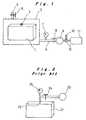
- FIG. 2illustrates a conventional battery sealing inspection method for verifying the sealing properties of a sealed battery case.
- the battery case 21is closed with a sealing plate, in which a hole 22 is formed for mounting a safety vent or the like.
- Compressed gasis introduced from a high-pressure gas source 23 via a valve 24 into the battery case 21, and the pressure inside the battery case 21 is measured by a pressure gauge 25.
- the valve 24is closed, and pressure change thereafter inside the battery case 21 is measured by the pressure gauge 25. If a fall in pressure is observed, then the battery is identified to be a defective battery in which gas is leaking out from the battery case.
- Another prior art battery sealing inspection method as disclosed in Japanese Laid-open Patent Application No. 4-25738includes introducing of compressed hydrogen gas into a battery case, and detecting the hydrogen gas leaking out from the battery case by collector plates and a semiconductor gas sensor.
- the amount of gas leaking from the battery case 21, if any,is fairly small relative to the volume of the battery case 21, and hence the pressure drop inside the battery case 21 due to gas leakage is very small. Therefore, detection accuracy is relatively low, because detection of gas leakage is possible only when there is a hole or a gap of more than 100 ⁇ m. In order to ensure accurate detection of gas leakage with this method, it takes at least 5 to 10 minutes per each battery, resulting in extremely poor efficiency. Moreover, since the compressed air is introduced into the battery case through the hole 22 for mounting a safety vent or the like prior to the actual mounting of such parts, it was necessary to inspect the sealing properties of the battery after the safety vent has been mounted on the battery case by welding. Thus the method involves a further leakage test with respect to the welds.
- an object of the present inventionis to provide a battery sealing inspection method whereby gas leakage from any location on a battery case is detected with a high degree of accuracy, good efficiency, and high reliability.
- the batteryis made to undergo charging and discharging before being placed within a sealed vessel.
- the sealed vesselis then evacuated, and a certain low pressure inside thereof is maintained for a predetermined period of time.
- the density of a gas within the sealed vessel, the gas being a gas generated within the batteryis measured, based on which it is determined whether there is a gas leak from the battery, by comparing the measured gas density with a preliminarily obtained reference value.
- the characteristic feature of the inventionis that the battery is charged and discharged prior to inspection so as to raise the internal pressure of the battery. Moreover, the sealed vessel in which the battery is placed is evacuated so as to make the internal pressure of the battery even higher relative to its ambient pressure. Since the battery is housed within the sealed vessel, a gas leak, even in a slightest amount, from any location of the battery is detected by the measurement of gas density within the sealed vessel. Thus the inspection method ensures detection of a hole or a crack as small as about 10 ⁇ m with good efficiency and high reliability.
- the inspectionshould preferably be performed immediately after the battery has undergone initial charging and discharging, where the internal pressure of the battery is particularly high.
- a battery which has been filled with electrolyte and has been sealedis placed within a sealed vessel, and is heated to a predetermined temperature.
- the sealed vesselis then evacuated, and a certain low pressure inside thereof is maintained for a predetermined period of time.
- the density of a gas within the sealed vessel, the gas being a gas generated within the batteryis measured, based on which it is determined whether there is a gas leak from the battery, by comparing the measured gas density with a preliminarily obtained reference value.
- the batteryis heated instead of subjected to charging and discharging in order to raise the internal pressure thereof. Therefore the inspection is performed with good efficiency and high reliability similarly to the above described embodiment.
- This embodimentis also effective for the inspection of batteries that have been stored for a long period of time after initial charging and discharging.
- the batteryshould preferably be heated to a temperature between 45 °C and 80 °C, and more preferably to 65 °C plus or minus 5 °C. This temperature range enables the battery internal pressure to be a level optimal for accurate detection of gas leakage, while preventing degradation of other members which will not withstand high heat such as separators.
- the gas generated within the batteryis hydrogen
- the reference valueis obtained by measuring hydrogen density in an ambient atmosphere prior to evacuation of the sealed vessel. In this way, the inspection is performed without being affected by the initial hydrogen density of ambient atmosphere, and gas leakage is accurately detected.
- reference numeral 1denotes a battery, such as a nickel metal hydride battery which is the object of inspection.
- the batteryincludes a safety vent 2 for discharging hydrogen gas externally in the event that the internal pressure has reached a predetermined value or above.
- Reference numeral 3denotes a hermetically sealed vessel for accommodating therein the battery 1 to perform sealing inspection.
- the vessel 3is connected to a vacuum exhaust tube 4 and is provided with an air inlet 5 which can be opened or closed by means of a valve 6.
- a pressure gauge 7, a valve 8, a vacuum pump 9, a switching valve 10, and a hydrogen density sensor 11,are serially connected to the vacuum exhaust tube 4 in this order from the sealed vessel side.
- the switching valve 10 connected between the vacuum pump 9 and the hydrogen density sensor 11has an air inlet 12, and switches from one to another of three states: In a first state, the outlet of the vacuum pump 9 is connected to the air inlet 12 of the switching valve 10; in a second state, the outlet of the vacuum pump 9 is connected to the hydrogen density sensor 11; and in a third state, the air inlet 12 of the switching valve 10 is connected to the hydrogen density sensor 11.
- the battery 1Before inspecting the sealing property of the battery 1, the battery 1 is filled with electrolyte, sealed, and made to undergo initial charging and discharging, so that the battery 1 is activated and an internal pressure generated therein. Meanwhile, the switching valve 10 is switched to the third state where the air inlet 12 of the switching valve 10 is communicated with the hydrogen density sensor 11, for measuring the hydrogen density in the atmosphere. The value thus obtained is taken as the atmospheric hydrogen density A.
- the battery 1 which has completed charging and dischargingis placed inside the sealed vessel 3, and the valve 6 of the air inlet 5 is closed, while the valve 8 of the vacuum exhaust tube 4 is opened. Meanwhile, the switching valve 10 is switched to the first state where the outlet of the vacuum pump 9 communicates with the air inlet 12 of the switching valve 10. The vacuum pump 9 is then operated, so as to reduce the pressure inside the sealed vessel 3 to 10 kPa.
- the switching valve 10After maintaining the internal pressure of the sealed vessel 3 at 10 kPa for approximately 1 minute to several minutes, the switching valve 10 is switched to the second state where the outlet of the vacuum pump 9 is connected to the hydrogen density sensor 11, so as to introduce the air inside the sealed vessel 3 into the hydrogen density sensor 11, for measuring the hydrogen density inside the sealed vessel 3. The value thus measured is taken as the sealed vessel hydrogen density B. Thereupon, the presence or absence of a gas escape from the battery 1 is judged based on a difference between the atmospheric hydrogen density A and the sealed vessel hydrogen density B.
- the battery 1prior to inspection, the battery 1 is made to undergo initial charging and discharging, so as to increase the internal pressure of the battery. Moreover, the battery is placed in the sealed vessel 3 so that the battery ambient pressure is in a vacuum state, whereby the internal pressure of the battery is made even higher relative to the outside of the battery. Since the inspection of gas leakage is effected by detecting small molecules of hydrogen gas, even a slightest gas leakage is readily detected. Moreover, since the battery 1 is placed inside the sealed vessel 3, it is possible to detect gas escape from any location of the battery 1 by the hydrogen density sensor 11. Accordingly, the inspection is performed in a short time with high accuracy, good efficiency, and high reliability.
- Defective batteriesare readily detected particularly when the inspection is performed on a battery immediately after the initial charging and discharging whereby the internal pressure of the battery has been increased. Also, the determination as to whether there is any gas leakage is not affected by the initial atmospheric gas density, because the judgment is made based on the difference between a reference value of the atmospheric hydrogen density A which is previously measured and the hydrogen density B in the sealed vessel 3.
- a modificationmay be made to the above described arrangement for battery sealing inspection method.
- the arrangementis substantially the same as that shown in Figure 1 , with the exception that a heater (not illustrated) such as an infrared lamp is provided within the sealed vessel 3 for heating the battery 1.
- a heatersuch as an infrared lamp
- the battery 1is filled with electrolyte, sealed, and placed within the sealed vessel 3. Meanwhile, the switching valve 10 is switched to the third state where the air inlet 12 of the switching valve 10 is communicated with the hydrogen density sensor 11, for measuring the hydrogen density in the atmosphere. The value thus obtained is taken as the atmospheric hydrogen density A.
- the battery 1is heated to a temperature of approximately 65 °C, by means of the infrared lamp (not illustrated) disposed inside the sealed vessel 3.
- the batteryis heated to a temperature of 45 °C to 80 °C, and more preferably to 65 °C plus or minus 5 °C.
- the equilibrium pressure inside the battery at a temperature of 45 °Cis 0.02 to 0.03 MPa, whereas it is 0.15 to 0.20 MPa at a temperature of 80 °C, and therefore, at a temperature below 45 °C, the internal pressure of the battery is too low to effect inspection to a desired degree of accuracy.
- the temperatureis above 80 °C, it will cause degradation of the other parts which will not withstand high heat such as separators.
- the interior of the sealed vessel 3is evacuated and after maintaining this state for a predetermined period of time, the hydrogen density inside the sealed vessel 3 is measured by the hydrogen density sensor 11, and hence a sealed vessel hydrogen density B is obtained.
- the presence or absence of a gas escape from the battery 1is judged from the difference between the atmospheric hydrogen density A and the sealed vessel hydrogen density B.
- the battery 1is heated so that gas is generated inside the battery 1 and the internal pressure of the battery raised, in a similar manner to a case where a battery 1 is subjected to initial charging and discharging.
- the inspection of sealing properties of the batteryis efficiently and reliably performed.
- This embodimentis particularly effective for the inspection of sealing property of batteries which have been stored for a long period of time after initial charging and charging.
- the batteryis either subjected to initial charging or discharging, or heated, to raise the internal pressure thereof, prior to the inspection of its sealing properties.
- the batteryis placed in a sealed vessel, which is evacuated to obtain a substantial difference between the pressure within the battery and its ambient pressure.
- the gas density within the sealed vesselis measured after a certain period of time, whereby gas escape from any location on the battery is detected in a reliable manner.
Landscapes
- Engineering & Computer Science (AREA)
- Manufacturing & Machinery (AREA)
- Chemical & Material Sciences (AREA)
- Chemical Kinetics & Catalysis (AREA)
- Electrochemistry (AREA)
- General Chemical & Material Sciences (AREA)
- Secondary Cells (AREA)
- Examining Or Testing Airtightness (AREA)
Description
- The present invention relates to a method of inspecting sealing property of battery.
Figure 2 illustrates a conventional battery sealing inspection method for verifying the sealing properties of a sealed battery case. Thebattery case 21 is closed with a sealing plate, in which ahole 22 is formed for mounting a safety vent or the like. Compressed gas is introduced from a high-pressure gas source 23 via avalve 24 into thebattery case 21, and the pressure inside thebattery case 21 is measured by a pressure gauge 25. When the pressure inside thebattery case 21 has reached a predetermined value, thevalve 24 is closed, and pressure change thereafter inside thebattery case 21 is measured by the pressure gauge 25. If a fall in pressure is observed, then the battery is identified to be a defective battery in which gas is leaking out from the battery case.- Another prior art battery sealing inspection method as disclosed in Japanese Laid-open Patent Application No.
4-25738 - In the inspection method illustrated in
Fig. 2 , the amount of gas leaking from thebattery case 21, if any, is fairly small relative to the volume of thebattery case 21, and hence the pressure drop inside thebattery case 21 due to gas leakage is very small. Therefore, detection accuracy is relatively low, because detection of gas leakage is possible only when there is a hole or a gap of more than 100µm. In order to ensure accurate detection of gas leakage with this method, it takes at least 5 to 10 minutes per each battery, resulting in extremely poor efficiency. Moreover, since the compressed air is introduced into the battery case through thehole 22 for mounting a safety vent or the like prior to the actual mounting of such parts, it was necessary to inspect the sealing properties of the battery after the safety vent has been mounted on the battery case by welding. Thus the method involves a further leakage test with respect to the welds. - In the method disclosed in
Japanese Laid-open Patent Application No. 4-25738 - In view of the foregoing problems of the prior art, an object of the present invention is to provide a battery sealing inspection method whereby gas leakage from any location on a battery case is detected with a high degree of accuracy, good efficiency, and high reliability.
- In a method for inspecting sealing properties of a battery according to the present invention, the battery is made to undergo charging and discharging before being placed within a sealed vessel. The sealed vessel is then evacuated, and a certain low pressure inside thereof is maintained for a predetermined period of time. The density of a gas within the sealed vessel, the gas being a gas generated within the battery, is measured, based on which it is determined whether there is a gas leak from the battery, by comparing the measured gas density with a preliminarily obtained reference value.
- The characteristic feature of the invention is that the battery is charged and discharged prior to inspection so as to raise the internal pressure of the battery. Moreover, the sealed vessel in which the battery is placed is evacuated so as to make the internal pressure of the battery even higher relative to its ambient pressure. Since the battery is housed within the sealed vessel, a gas leak, even in a slightest amount, from any location of the battery is detected by the measurement of gas density within the sealed vessel. Thus the inspection method ensures detection of a hole or a crack as small as about 10µm with good efficiency and high reliability.
- The inspection should preferably be performed immediately after the battery has undergone initial charging and discharging, where the internal pressure of the battery is particularly high.
- In another embodiment of the invention, a battery which has been filled with electrolyte and has been sealed is placed within a sealed vessel, and is heated to a predetermined temperature. The sealed vessel is then evacuated, and a certain low pressure inside thereof is maintained for a predetermined period of time. The density of a gas within the sealed vessel, the gas being a gas generated within the battery, is measured, based on which it is determined whether there is a gas leak from the battery, by comparing the measured gas density with a preliminarily obtained reference value.
- In this embodiment, the battery is heated instead of subjected to charging and discharging in order to raise the internal pressure thereof. Therefore the inspection is performed with good efficiency and high reliability similarly to the above described embodiment. This embodiment is also effective for the inspection of batteries that have been stored for a long period of time after initial charging and discharging.
- The battery should preferably be heated to a temperature between 45 °C and 80 °C, and more preferably to 65 °C plus or
minus 5 °C. This temperature range enables the battery internal pressure to be a level optimal for accurate detection of gas leakage, while preventing degradation of other members which will not withstand high heat such as separators. - The gas generated within the battery is hydrogen, and the reference value is obtained by measuring hydrogen density in an ambient atmosphere prior to evacuation of the sealed vessel. In this way, the inspection is performed without being affected by the initial hydrogen density of ambient atmosphere, and gas leakage is accurately detected.
- Preferred embodiments of the present invention will be hereinafter described with reference to the accompanying drawings, in which:
Fig. 1 is a schematic diagram showing one embodiment of a battery sealing inspection method according to the present invention; andFig. 2 is a schematic diagram showing a conventional battery sealing inspection method.- In
Fig. 1 , reference numeral 1 denotes a battery, such as a nickel metal hydride battery which is the object of inspection. The battery includes asafety vent 2 for discharging hydrogen gas externally in the event that the internal pressure has reached a predetermined value or above.Reference numeral 3 denotes a hermetically sealed vessel for accommodating therein the battery 1 to perform sealing inspection. Thevessel 3 is connected to avacuum exhaust tube 4 and is provided with anair inlet 5 which can be opened or closed by means of avalve 6. - A
pressure gauge 7, avalve 8, avacuum pump 9, aswitching valve 10, and ahydrogen density sensor 11, are serially connected to thevacuum exhaust tube 4 in this order from the sealed vessel side. Theswitching valve 10 connected between thevacuum pump 9 and thehydrogen density sensor 11 has anair inlet 12, and switches from one to another of three states: In a first state, the outlet of thevacuum pump 9 is connected to theair inlet 12 of theswitching valve 10; in a second state, the outlet of thevacuum pump 9 is connected to thehydrogen density sensor 11; and in a third state, theair inlet 12 of theswitching valve 10 is connected to thehydrogen density sensor 11. - Before inspecting the sealing property of the battery 1, the battery 1 is filled with electrolyte, sealed, and made to undergo initial charging and discharging, so that the battery 1 is activated and an internal pressure generated therein. Meanwhile, the
switching valve 10 is switched to the third state where theair inlet 12 of theswitching valve 10 is communicated with thehydrogen density sensor 11, for measuring the hydrogen density in the atmosphere. The value thus obtained is taken as the atmospheric hydrogen density A. - Thereupon, the battery 1 which has completed charging and discharging is placed inside the sealed
vessel 3, and thevalve 6 of theair inlet 5 is closed, while thevalve 8 of thevacuum exhaust tube 4 is opened. Meanwhile, theswitching valve 10 is switched to the first state where the outlet of thevacuum pump 9 communicates with theair inlet 12 of theswitching valve 10. Thevacuum pump 9 is then operated, so as to reduce the pressure inside the sealedvessel 3 to 10 kPa. - After maintaining the internal pressure of the sealed
vessel 3 at 10 kPa for approximately 1 minute to several minutes, theswitching valve 10 is switched to the second state where the outlet of thevacuum pump 9 is connected to thehydrogen density sensor 11, so as to introduce the air inside the sealedvessel 3 into thehydrogen density sensor 11, for measuring the hydrogen density inside the sealedvessel 3. The value thus measured is taken as the sealed vessel hydrogen density B. Thereupon, the presence or absence of a gas escape from the battery 1 is judged based on a difference between the atmospheric hydrogen density A and the sealed vessel hydrogen density B. - According to this embodiment of the invention, prior to inspection, the battery 1 is made to undergo initial charging and discharging, so as to increase the internal pressure of the battery. Moreover, the battery is placed in the sealed
vessel 3 so that the battery ambient pressure is in a vacuum state, whereby the internal pressure of the battery is made even higher relative to the outside of the battery. Since the inspection of gas leakage is effected by detecting small molecules of hydrogen gas, even a slightest gas leakage is readily detected. Moreover, since the battery 1 is placed inside the sealedvessel 3, it is possible to detect gas escape from any location of the battery 1 by thehydrogen density sensor 11. Accordingly, the inspection is performed in a short time with high accuracy, good efficiency, and high reliability. Defective batteries are readily detected particularly when the inspection is performed on a battery immediately after the initial charging and discharging whereby the internal pressure of the battery has been increased. Also, the determination as to whether there is any gas leakage is not affected by the initial atmospheric gas density, because the judgment is made based on the difference between a reference value of the atmospheric hydrogen density A which is previously measured and the hydrogen density B in the sealedvessel 3. - A modification may be made to the above described arrangement for battery sealing inspection method. The arrangement is substantially the same as that shown in
Figure 1 , with the exception that a heater (not illustrated) such as an infrared lamp is provided within the sealedvessel 3 for heating the battery 1. - For the sealing inspection, the battery 1 is filled with electrolyte, sealed, and placed within the sealed
vessel 3. Meanwhile, theswitching valve 10 is switched to the third state where theair inlet 12 of theswitching valve 10 is communicated with thehydrogen density sensor 11, for measuring the hydrogen density in the atmosphere. The value thus obtained is taken as the atmospheric hydrogen density A. - Thereupon, the battery 1 is heated to a temperature of approximately 65 °C, by means of the infrared lamp (not illustrated) disposed inside the sealed
vessel 3. Preferably, the battery is heated to a temperature of 45 °C to 80 °C, and more preferably to 65 °C plus orminus 5 °C. This is because the equilibrium pressure inside the battery at a temperature of 45 °C is 0.02 to 0.03 MPa, whereas it is 0.15 to 0.20 MPa at a temperature of 80 °C, and therefore, at a temperature below 45 °C, the internal pressure of the battery is too low to effect inspection to a desired degree of accuracy. On the other hand, if the temperature is above 80 °C, it will cause degradation of the other parts which will not withstand high heat such as separators. - Similarly to the aforementioned embodiment, the interior of the sealed
vessel 3 is evacuated and after maintaining this state for a predetermined period of time, the hydrogen density inside the sealedvessel 3 is measured by thehydrogen density sensor 11, and hence a sealed vessel hydrogen density B is obtained. The presence or absence of a gas escape from the battery 1 is judged from the difference between the atmospheric hydrogen density A and the sealed vessel hydrogen density B. - According to this embodiment, the battery 1 is heated so that gas is generated inside the battery 1 and the internal pressure of the battery raised, in a similar manner to a case where a battery 1 is subjected to initial charging and discharging. Thus the inspection of sealing properties of the battery is efficiently and reliably performed.
- This embodiment is particularly effective for the inspection of sealing property of batteries which have been stored for a long period of time after initial charging and charging.
- According to the battery sealing inspection method of the present invention, the battery is either subjected to initial charging or discharging, or heated, to raise the internal pressure thereof, prior to the inspection of its sealing properties. The battery is placed in a sealed vessel, which is evacuated to obtain a substantial difference between the pressure within the battery and its ambient pressure. The gas density within the sealed vessel is measured after a certain period of time, whereby gas escape from any location on the battery is detected in a reliable manner. With this method, even a slightest amount of gas leaking from anywhere on the battery causes changes in the gas density within the sealed vessel, and therefore gas leakage is detected accurately for a short time with good efficiency and high reliability.
Claims (10)
- A method of inspecting sealing properties of a battery, comprising the steps of:charging and discharging the battery (1);placing the battery within a sealed vessel (3);evacuating the interior of the sealed vessel and maintaining a predetermined low pressure level for a period of time;measuring density of a gas within the sealed vessel, the gas being a gas generated within the battery; anddetermining whether there is a gas leak from the battery by comparing the measured gas density with a preliminarily obtained reference value.
- A method of inspecting sealing properties of a battery according to claim 1, wherein the battery is heated before the density of the gas in the sealed vessel is measured.
- A method of inspecting sealing properties of a battery, comprising the steps of:placing the battery (1) which has been filled with electrolyte and has been sealed inside a sealed vessel (3);heating the battery;evacuating the interior of the sealed vessel and maintaining a predetermined low pressure level for a period of time;measuring density of a gas within the sealed vessel, the gas being a gas generated within the battery; anddetermining whether there is a gas leak from the battery by comparing the measured gas density with a preliminarily obtained reference value.
- A method of inspecting sealing properties of a battery according to claim 3, wherein the battery is heated to a temperature between 45°C and 80°C.
- A method of inspecting sealing properties of a battery according to claim 4, wherein the battery is heated to a temperature of 60°C ± 5°C.
- A method of inspecting sealing properties of a battery according to any preceding claim, wherein the inspection is performed immediately after the battery has undergone initial charging and discharging.
- A method of inspecting sealing properties of a battery according to any one of the preceding claims, wherein the reference value is obtained by measuring density of the gas in an ambient atmosphere prior to evacuation of the sealed vessel.
- A method of inspecting sealing properties of a battery according to any one of the preceding claims, wherein the gas generated within the battery is hydrogen.
- An apparatus for inspecting sealing properties of a battery, comprising:a vessel (3) for housing therein a battery (1) to be inspected, provided with a vacuum pump (9) so as to be evacuated;a hydrogen density sensor (11) connected to the vacuum pump; andmeans (10) for switchably connecting the vacuum pump with the hydrogen density sensor, the vacuum pump with atmosphere, and the hydrogen density sensor with atmosphere.
- An apparatus for inspecting sealing properties of a battery according to Claim 9 further comprising a heater provided within the vessel.
Applications Claiming Priority (2)
| Application Number | Priority Date | Filing Date | Title |
|---|---|---|---|
| JP2000044101AJP4671462B2 (en) | 2000-02-22 | 2000-02-22 | Airtight inspection method for nickel metal hydride secondary battery |
| JP2000044101 | 2000-02-22 |
Publications (2)
| Publication Number | Publication Date |
|---|---|
| EP1130668A1 EP1130668A1 (en) | 2001-09-05 |
| EP1130668B1true EP1130668B1 (en) | 2010-05-05 |
Family
ID=18566920
Family Applications (1)
| Application Number | Title | Priority Date | Filing Date |
|---|---|---|---|
| EP01301511AExpired - LifetimeEP1130668B1 (en) | 2000-02-22 | 2001-02-20 | Battery sealing inspection method |
Country Status (4)
| Country | Link |
|---|---|
| US (1) | US6635379B2 (en) |
| EP (1) | EP1130668B1 (en) |
| JP (1) | JP4671462B2 (en) |
| DE (1) | DE60142001D1 (en) |
Families Citing this family (65)
| Publication number | Priority date | Publication date | Assignee | Title |
|---|---|---|---|---|
| KR100416784B1 (en)* | 2001-12-14 | 2004-01-31 | 엘지전자 주식회사 | leak inspection device and methode of secondary battery |
| JP5034156B2 (en) | 2004-07-02 | 2012-09-26 | トヨタ自動車株式会社 | Nickel metal hydride storage battery |
| JP4899313B2 (en)* | 2004-12-22 | 2012-03-21 | トヨタ自動車株式会社 | Battery, battery manufacturing method, and electrolyte leakage inspection method |
| JP4843947B2 (en)* | 2005-01-19 | 2011-12-21 | トヨタ自動車株式会社 | Sealed battery manufacturing method and airtightness inspection apparatus |
| DE602006006897D1 (en)* | 2006-03-31 | 2009-07-02 | Sony Deutschland Gmbh | System for detecting a leak in a battery |
| KR101025516B1 (en) | 2006-09-11 | 2011-04-04 | 주식회사 엘지화학 | Volume change measuring device of battery cell |
| JP4434246B2 (en)* | 2007-07-24 | 2010-03-17 | トヨタ自動車株式会社 | Air battery system |
| JP5430978B2 (en) | 2009-03-10 | 2014-03-05 | 三洋電機株式会社 | Sealed battery and manufacturing method thereof |
| EP2517001A4 (en)* | 2009-12-22 | 2014-08-20 | Ima Life North America Inc | Monitoring freeze drying with gas measurement on vaccum pump exhaust |
| DE102010024134B4 (en)* | 2010-06-17 | 2012-07-12 | INPRO Innovationsgesellschaft für fortgeschrittene Produktionssysteme in der Fahrzeugindustrie mbH | Method for the non-destructive testing of at least partially open hollow-shaped components or system components for leak-tightness in series production |
| JP6142532B2 (en)* | 2010-06-30 | 2017-06-07 | 株式会社Gsユアサ | Secondary battery manufacturing method, secondary battery and assembled battery |
| CN102226731A (en)* | 2010-12-30 | 2011-10-26 | 湖南科霸汽车动力电池有限责任公司 | Method and device applicable to nickel-metal hydride batteries and used for selecting batteries with electrolyte leakage |
| JP5733146B2 (en)* | 2011-10-04 | 2015-06-10 | トヨタ自動車株式会社 | Secondary battery measuring method and measuring system |
| CN102539080A (en)* | 2012-01-06 | 2012-07-04 | 肇庆理士电源技术有限公司 | Sealing detection method and system for lead-acid storage battery |
| DE102012205928A1 (en)* | 2012-04-12 | 2013-10-17 | Robert Bosch Gmbh | Method and apparatus for locating a defect in an electrochemical store and defect location system |
| JP5790604B2 (en)* | 2012-08-07 | 2015-10-07 | トヨタ自動車株式会社 | Manufacturing method of sealed battery |
| JP6139122B2 (en)* | 2012-12-12 | 2017-05-31 | 富士電機株式会社 | Leak inspection method and leak inspection apparatus |
| FR3000215B1 (en)* | 2012-12-21 | 2016-02-05 | Aneolia | DEVICE AND METHOD FOR TESTING A SAMPLE, ESPECIALLY DISCRIMINATION OF A GAS FROM A SAMPLE |
| JP5751246B2 (en)* | 2012-12-26 | 2015-07-22 | トヨタ自動車株式会社 | Manufacturing method of sealed battery |
| JP6057129B2 (en)* | 2013-03-21 | 2017-01-11 | トヨタ自動車株式会社 | Manufacturing method of sealed battery |
| JP6057132B2 (en)* | 2013-05-17 | 2017-01-11 | トヨタ自動車株式会社 | Manufacturing method of sealed battery |
| CN103674451A (en)* | 2013-12-20 | 2014-03-26 | 天津力神电池股份有限公司 | Leakage detection method and device for peripheral welding of lithium-ion battery |
| WO2015111665A1 (en)* | 2014-01-23 | 2015-07-30 | 株式会社豊田自動織機 | Power storage device manufacturing method, manufacturing device, liquid injection device, and liquid injection method |
| DE102014205032A1 (en)* | 2014-03-18 | 2015-09-24 | Inficon Gmbh | Density increase measurement in foil chamber |
| JP5939269B2 (en)* | 2014-03-19 | 2016-06-22 | トヨタ自動車株式会社 | Battery deterioration judgment device |
| JP6265085B2 (en)* | 2014-08-29 | 2018-01-24 | 株式会社豊田自動織機 | Airtightness inspection device for battery pack |
| CN104215409B (en)* | 2014-09-10 | 2017-03-08 | 国家电网公司 | A kind of method of monitoring bushing shell for transformer sealing condition |
| JP6497505B2 (en)* | 2014-12-19 | 2019-04-10 | 日産自動車株式会社 | Gas detection apparatus for electrochemical device evaluation apparatus and gas sensor sensitivity recovery method for gas detection apparatus |
| JP2016148525A (en)* | 2015-02-10 | 2016-08-18 | Tdk株式会社 | Airtight inspection device |
| JP6503847B2 (en)* | 2015-03-31 | 2019-04-24 | 大日本印刷株式会社 | Method of manufacturing battery |
| CN104729798A (en)* | 2015-04-02 | 2015-06-24 | 天津力神电池股份有限公司 | Battery sealing performance testing method |
| JP6515692B2 (en)* | 2015-06-11 | 2019-05-22 | 株式会社豊田自動織機 | Airtightness inspection device and airtightness inspection method |
| JP2017009539A (en)* | 2015-06-25 | 2017-01-12 | 株式会社住化分析センター | Gas analysis device and gas analysis method |
| CN105466641A (en)* | 2015-10-15 | 2016-04-06 | 杭州伯坦科技工程有限公司 | Battery leakage rapid detection device and detection method thereof |
| CN105319021A (en)* | 2015-10-30 | 2016-02-10 | 北京新能源汽车股份有限公司 | Sealing detection method and system for battery pack |
| KR102034699B1 (en)* | 2015-12-15 | 2019-10-21 | 주식회사 엘지화학 | Quantitative Analysis Device for Measuring Leakage Level of Electrolyte from Battery Cell and Method for Inspection of Battery Cell with the Same |
| CN108701876B (en)* | 2016-02-17 | 2021-06-22 | 丰田自动车欧洲公司 | System and method for battery discharge control |
| US10818978B2 (en) | 2016-05-13 | 2020-10-27 | Nio Usa, Inc. | Battery module having a pressure sensor |
| US10877011B2 (en) | 2016-06-29 | 2020-12-29 | Nexceris, Llc | Systems and methods for monitoring for a gas analyte |
| CN107632049B (en) | 2016-07-19 | 2021-07-13 | 松下知识产权经营株式会社 | Detection Systems |
| CN106197903A (en)* | 2016-08-31 | 2016-12-07 | 无锡东恒新能源科技有限公司 | A kind of lithium battery leak test plant |
| CN106556496A (en)* | 2016-10-09 | 2017-04-05 | 深圳拓邦新能源技术有限公司 | Battery negative pressure air-tightness detection method |
| CN106441744B (en)* | 2016-12-13 | 2018-08-17 | 力信(江苏)能源科技有限责任公司 | A kind of lithium ion square power battery leak testing device and its test leakage technique |
| CN110418962B (en)* | 2017-02-03 | 2022-02-11 | 奈克斯赛瑞斯创新控股有限责任公司 | Systems and methods for monitoring gas analytes |
| US10775263B2 (en)* | 2017-07-31 | 2020-09-15 | Nio Usa, Inc. | Systems and methods for diagnosing seal integrity in a battery |
| KR102256488B1 (en)* | 2017-09-14 | 2021-05-27 | 주식회사 엘지에너지솔루션 | Gas measuring equipment for rechargeable battery test |
| CN107607263B (en)* | 2017-09-26 | 2020-01-03 | 歌尔股份有限公司 | Waterproof detection structure |
| CN110007244B (en)* | 2018-01-03 | 2024-07-30 | 深圳前海久禾科技发展有限公司 | Battery testing machine and testing method |
| CN108195831A (en)* | 2018-01-10 | 2018-06-22 | 华霆(合肥)动力技术有限公司 | Battery leakage detection method and device |
| IT201800005260A1 (en)* | 2018-05-11 | 2019-11-11 | METHOD FOR TIGHTNESS CHECK OF A BATTERY CELL AND RELATIVE CHECK SYSTEM | |
| KR20190139122A (en)* | 2018-06-07 | 2019-12-17 | 주식회사 엘지화학 | A chamber for real-time analysis of the generated gas in the secondary battery and a system thereof |
| CN111509321B (en)* | 2019-01-30 | 2021-07-20 | 北京新能源汽车股份有限公司 | Battery pack system, battery pack air tightness detection method and electric automobile |
| CN110261044B (en)* | 2019-06-29 | 2024-08-09 | 广东利元亨智能装备股份有限公司 | Air tightness detection equipment |
| DE102019121462B4 (en)* | 2019-08-08 | 2021-12-09 | Inficon Gmbh | Procedure for leak testing a liquid-filled test object |
| EP3736902B1 (en)* | 2020-07-15 | 2022-11-23 | Marposs | System and method for leak testing a battery cell |
| CN113390981A (en)* | 2021-05-24 | 2021-09-14 | 超威电源集团有限公司 | Storage battery gassing test equipment and method |
| CN113514197B (en)* | 2021-07-01 | 2023-04-07 | 广舜检测技术(上海)有限公司 | Vehicle battery PACK package leakage detection system and detection method based on accumulative test |
| KR20230039371A (en)* | 2021-09-14 | 2023-03-21 | 현대자동차주식회사 | Pouch cell vent pressure measurement device |
| CN216349385U (en)* | 2021-10-13 | 2022-04-19 | 宁德时代新能源科技股份有限公司 | Battery cell detection device |
| WO2023085523A1 (en)* | 2021-11-10 | 2023-05-19 | (주)엔에스 | Secondary battery manufacturing device and second battery leak inspection method therefor |
| CN115096516B (en)* | 2022-07-04 | 2023-04-11 | 深圳市誉辰智能装备股份有限公司 | Double-vacuum four-cavity air tightness detection method and detection machine for square-shell battery |
| CN116558737B (en)* | 2023-07-07 | 2023-10-27 | 广汽埃安新能源汽车股份有限公司 | Compatible battery cell withstand voltage testing device and application method thereof |
| JP2025062778A (en)* | 2023-10-03 | 2025-04-15 | 株式会社豊田自動織機 | Energy storage module manufacturing method |
| CN120213362A (en)* | 2023-12-27 | 2025-06-27 | 宁德时代新能源科技股份有限公司 | Airtightness detection method, airtightness detection device and battery monomer manufacturing system |
| JP7592922B1 (en)* | 2024-05-20 | 2024-12-02 | 株式会社コベルコ科研 | Analysis method and analysis device |
Family Cites Families (20)
| Publication number | Priority date | Publication date | Assignee | Title |
|---|---|---|---|---|
| US3793876A (en)* | 1972-08-10 | 1974-02-26 | Gould Inc | Battery terminal leak detector |
| CA1044325A (en)* | 1976-04-30 | 1978-12-12 | Her Majesty The Queen In Right Of Canada As Represented By The Minister Of National Defence Of Her Majesty's Canadian Government | Battery self-discharge indicator |
| US4433294A (en) | 1981-06-05 | 1984-02-21 | Firing Circuits, Inc. | Method and apparatus for testing a battery |
| US4913986A (en)* | 1983-09-28 | 1990-04-03 | Medtronic, Inc. | Battery fill-post seal arrangement for hermeticity leakage testing |
| JPS6199273A (en)* | 1984-10-19 | 1986-05-17 | Hitachi Maxell Ltd | Thionyl chloride-lithium battery |
| FR2611314A3 (en) | 1987-02-19 | 1988-08-26 | Chloride France Sa | Method and device for monitoring the reserve of a storage battery |
| JP2875822B2 (en)* | 1989-09-21 | 1999-03-31 | 東芝電池株式会社 | Method for manufacturing nickel-hydrogen secondary battery |
| JP3021545B2 (en)* | 1990-05-21 | 2000-03-15 | 松下電器産業株式会社 | Battery tightness inspection device |
| CA2018639A1 (en) | 1990-06-08 | 1991-12-08 | James D. Blair | Method and apparatus for comparing fuel cell voltage |
| JP3120122B2 (en) | 1991-07-16 | 2000-12-25 | 松下電器産業株式会社 | Airtightness inspection method and device for lead storage battery |
| JPH0845541A (en)* | 1994-07-29 | 1996-02-16 | Sanyo Electric Co Ltd | Sealing degree deciding method of sealed battery |
| US5581170A (en) | 1994-12-12 | 1996-12-03 | Unitrode Corporation | Battery protector |
| JP3251499B2 (en) | 1996-05-31 | 2002-01-28 | 矢崎総業株式会社 | Battery remaining capacity measurement device |
| US5937917A (en)* | 1996-06-12 | 1999-08-17 | Matsushita Electric Industrial Co., Ltd. | Charging method and charging structure of combustible gas and oxidizer gas, and material to be charged by using the charging method and the charging structure |
| NO971841L (en) | 1997-04-22 | 1998-10-23 | Einar Gotaas | Method of monitoring battery operation |
| US6313637B1 (en) | 1997-11-20 | 2001-11-06 | Denso Corporation | Voltage detecting device for set battery |
| US6002238A (en) | 1998-09-11 | 1999-12-14 | Champlin; Keith S. | Method and apparatus for measuring complex impedance of cells and batteries |
| JP4030217B2 (en) | 1999-03-12 | 2008-01-09 | トヨタ自動車株式会社 | Abnormality determination device and abnormality determination method for battery pack |
| US6351983B1 (en)* | 1999-04-12 | 2002-03-05 | The Regents Of The University Of California | Portable gas chromatograph mass spectrometer for on-site chemical analyses |
| JP2001023699A (en) | 1999-07-05 | 2001-01-26 | Yazaki Corp | Battery management device |
- 2000
- 2000-02-22JPJP2000044101Apatent/JP4671462B2/ennot_activeExpired - Fee Related
- 2001
- 2001-02-20DEDE60142001Tpatent/DE60142001D1/ennot_activeExpired - Lifetime
- 2001-02-20EPEP01301511Apatent/EP1130668B1/ennot_activeExpired - Lifetime
- 2001-02-21USUS09/788,537patent/US6635379B2/ennot_activeExpired - Lifetime
Also Published As
| Publication number | Publication date |
|---|---|
| JP4671462B2 (en) | 2011-04-20 |
| US6635379B2 (en) | 2003-10-21 |
| US20010016278A1 (en) | 2001-08-23 |
| DE60142001D1 (en) | 2010-06-17 |
| JP2001236986A (en) | 2001-08-31 |
| EP1130668A1 (en) | 2001-09-05 |
Similar Documents
| Publication | Publication Date | Title |
|---|---|---|
| EP1130668B1 (en) | Battery sealing inspection method | |
| KR102273782B1 (en) | Apparatus for leak detection of battery cell and method for leak detection of battery cell | |
| US5625141A (en) | Sealed parts leak testing method and apparatus for helium spectrometer leak detection | |
| US7587928B2 (en) | Leak inspection device | |
| CA2324196C (en) | Sealed battery and method for manufacturing sealed battery | |
| US20040134259A1 (en) | Method for leak testing of electrochemical elements | |
| US6314794B1 (en) | Method and apparatus for detecting leaks in heat exchangers for motor vehicles | |
| WO2006093935A2 (en) | Apparatus and process for leak-testing and qualification of fluid dispensing vessels | |
| EP3736902B1 (en) | System and method for leak testing a battery cell | |
| EP3736903A2 (en) | Method for leak testing a battery cell | |
| EP0168972A2 (en) | Hermeticity testing method and system | |
| JP2002117901A (en) | Sealed battery and its manufacturing method | |
| CN118362258A (en) | Lithium battery air tightness detection system and detection method | |
| CN117091772A (en) | Air tightness detection method and air tightness detection system | |
| US7150936B2 (en) | Sealed battery and method for manufacturing sealed battery | |
| JP4089389B2 (en) | Sealed battery airtightness inspection method and apparatus | |
| JP3983479B2 (en) | Battery leakage inspection device | |
| KR102726066B1 (en) | Leakage inspection method for secondary batteries | |
| JPH0845541A (en) | Sealing degree deciding method of sealed battery | |
| CN218002856U (en) | Battery detection device and battery detection system | |
| CN112781785A (en) | Method for testing internal vacuum degree of soft package battery and quality control method of soft package battery | |
| CN115127736A (en) | Tightness testing device and tightness testing system | |
| CN114623985A (en) | Soft package battery leakage detection method and application method thereof | |
| CN222318357U (en) | Lithium battery air tightness detection device and detection system | |
| KR102718644B1 (en) | Vacuum leak detection method |
Legal Events
| Date | Code | Title | Description |
|---|---|---|---|
| PUAI | Public reference made under article 153(3) epc to a published international application that has entered the european phase | Free format text:ORIGINAL CODE: 0009012 | |
| AK | Designated contracting states | Kind code of ref document:A1 Designated state(s):AT BE CH CY DE DK ES FI FR GB GR IE IT LI LU MC NL PT SE TR | |
| AX | Request for extension of the european patent | Free format text:AL;LT;LV;MK;RO;SI | |
| 17P | Request for examination filed | Effective date:20020204 | |
| AKX | Designation fees paid | Free format text:DE FR GB | |
| RAP1 | Party data changed (applicant data changed or rights of an application transferred) | Owner name:PANASONIC CORPORATION Owner name:TOYOTA JIDOSHA KABUSHIKI KAISHA | |
| GRAP | Despatch of communication of intention to grant a patent | Free format text:ORIGINAL CODE: EPIDOSNIGR1 | |
| GRAS | Grant fee paid | Free format text:ORIGINAL CODE: EPIDOSNIGR3 | |
| GRAA | (expected) grant | Free format text:ORIGINAL CODE: 0009210 | |
| AK | Designated contracting states | Kind code of ref document:B1 Designated state(s):DE FR GB | |
| REG | Reference to a national code | Ref country code:GB Ref legal event code:FG4D | |
| REF | Corresponds to: | Ref document number:60142001 Country of ref document:DE Date of ref document:20100617 Kind code of ref document:P | |
| PLBE | No opposition filed within time limit | Free format text:ORIGINAL CODE: 0009261 | |
| STAA | Information on the status of an ep patent application or granted ep patent | Free format text:STATUS: NO OPPOSITION FILED WITHIN TIME LIMIT | |
| 26N | No opposition filed | Effective date:20110208 | |
| REG | Reference to a national code | Ref country code:DE Ref legal event code:R097 Ref document number:60142001 Country of ref document:DE Effective date:20110207 | |
| REG | Reference to a national code | Ref country code:DE Ref legal event code:R084 Ref document number:60142001 Country of ref document:DE | |
| REG | Reference to a national code | Ref country code:GB Ref legal event code:746 Effective date:20151124 | |
| REG | Reference to a national code | Ref country code:FR Ref legal event code:PLFP Year of fee payment:16 | |
| REG | Reference to a national code | Ref country code:FR Ref legal event code:PLFP Year of fee payment:17 | |
| REG | Reference to a national code | Ref country code:FR Ref legal event code:PLFP Year of fee payment:18 | |
| PGFP | Annual fee paid to national office [announced via postgrant information from national office to epo] | Ref country code:DE Payment date:20200204 Year of fee payment:20 Ref country code:GB Payment date:20200212 Year of fee payment:20 | |
| PGFP | Annual fee paid to national office [announced via postgrant information from national office to epo] | Ref country code:FR Payment date:20200113 Year of fee payment:20 | |
| REG | Reference to a national code | Ref country code:DE Ref legal event code:R071 Ref document number:60142001 Country of ref document:DE | |
| REG | Reference to a national code | Ref country code:GB Ref legal event code:PE20 Expiry date:20210219 | |
| PG25 | Lapsed in a contracting state [announced via postgrant information from national office to epo] | Ref country code:GB Free format text:LAPSE BECAUSE OF EXPIRATION OF PROTECTION Effective date:20210219 |