EP1129470B1 - Electric lamp - Google Patents
Electric lampDownload PDFInfo
- Publication number
- EP1129470B1 EP1129470B1EP00964076AEP00964076AEP1129470B1EP 1129470 B1EP1129470 B1EP 1129470B1EP 00964076 AEP00964076 AEP 00964076AEP 00964076 AEP00964076 AEP 00964076AEP 1129470 B1EP1129470 B1EP 1129470B1
- Authority
- EP
- European Patent Office
- Prior art keywords
- light
- electric lamp
- lamp
- pigment
- coating
- Prior art date
- Legal status (The legal status is an assumption and is not a legal conclusion. Google has not performed a legal analysis and makes no representation as to the accuracy of the status listed.)
- Expired - Lifetime
Links
- 238000000576coating methodMethods0.000claimsabstractdescription87
- 239000011248coating agentSubstances0.000claimsabstractdescription72
- 239000000049pigmentSubstances0.000claimsabstractdescription27
- 239000000203mixtureSubstances0.000claimsabstractdescription24
- VYPSYNLAJGMNEJ-UHFFFAOYSA-NSilicium dioxideChemical compoundO=[Si]=OVYPSYNLAJGMNEJ-UHFFFAOYSA-N0.000claimsabstractdescription16
- NNGHIEIYUJKFQS-UHFFFAOYSA-Lhydroxy(oxo)iron;zincChemical compound[Zn].O[Fe]=O.O[Fe]=ONNGHIEIYUJKFQS-UHFFFAOYSA-L0.000claimsabstractdescription13
- 125000000217alkyl groupChemical group0.000claimsabstractdescription10
- 150000004756silanesChemical class0.000claimsabstractdescription10
- 125000003118aryl groupChemical group0.000claimsabstractdescription7
- 125000001997phenyl groupChemical group[H]C1=C([H])C([H])=C(*)C([H])=C1[H]0.000claimsabstractdescription7
- BPQQTUXANYXVAA-UHFFFAOYSA-NOrthosilicateChemical compound[O-][Si]([O-])([O-])[O-]BPQQTUXANYXVAA-UHFFFAOYSA-N0.000claimsabstractdescription4
- USEGQPUGEPSVQL-UHFFFAOYSA-N[Pr].[Zr]Chemical compound[Pr].[Zr]USEGQPUGEPSVQL-UHFFFAOYSA-N0.000claimsabstractdescription4
- 150000001875compoundsChemical class0.000claimsabstractdescription3
- UQSXHKLRYXJYBZ-UHFFFAOYSA-NIron oxideChemical compound[Fe]=OUQSXHKLRYXJYBZ-UHFFFAOYSA-N0.000claimsdescription24
- 229910052797bismuthInorganic materials0.000claimsdescription10
- JCXGWMGPZLAOME-UHFFFAOYSA-Nbismuth atomChemical compound[Bi]JCXGWMGPZLAOME-UHFFFAOYSA-N0.000claimsdescription10
- LSGOVYNHVSXFFJ-UHFFFAOYSA-Nvanadate(3-)Chemical compound[O-][V]([O-])([O-])=OLSGOVYNHVSXFFJ-UHFFFAOYSA-N0.000claimsdescription10
- PLDDOISOJJCEMH-UHFFFAOYSA-Nneodymium(3+);oxygen(2-)Chemical compound[O-2].[O-2].[O-2].[Nd+3].[Nd+3]PLDDOISOJJCEMH-UHFFFAOYSA-N0.000claimsdescription8
- OAICVXFJPJFONN-UHFFFAOYSA-NPhosphorusChemical compound[P]OAICVXFJPJFONN-UHFFFAOYSA-N0.000claimsdescription4
- 239000001023inorganic pigmentSubstances0.000claimsdescription4
- CRHLEZORXKQUEI-UHFFFAOYSA-Ndialuminum;cobalt(2+);oxygen(2-)Chemical compound[O-2].[O-2].[O-2].[O-2].[O-2].[Al+3].[Al+3].[Co+2].[Co+2]CRHLEZORXKQUEI-UHFFFAOYSA-N0.000claimsdescription3
- JEIPFZHSYJVQDO-UHFFFAOYSA-Niron(III) oxideInorganic materialsO=[Fe]O[Fe]=OJEIPFZHSYJVQDO-UHFFFAOYSA-N0.000abstractdescription20
- 229910001308Zinc ferriteInorganic materials0.000abstractdescription10
- 229910002915BiVO4Inorganic materials0.000abstractdescription8
- 238000006243chemical reactionMethods0.000abstractdescription4
- 239000002105nanoparticleSubstances0.000abstractdescription4
- 238000003980solgel methodMethods0.000abstractdescription4
- 229910019114CoAl2O4Inorganic materials0.000abstractdescription2
- -1Nd2O5Inorganic materials0.000abstract1
- XLOMVQKBTHCTTD-UHFFFAOYSA-Nzinc oxideInorganic materials[Zn]=OXLOMVQKBTHCTTD-UHFFFAOYSA-N0.000abstract1
- LFQSCWFLJHTTHZ-UHFFFAOYSA-NEthanolChemical compoundCCOLFQSCWFLJHTTHZ-UHFFFAOYSA-N0.000description14
- BFXIKLCIZHOAAZ-UHFFFAOYSA-NmethyltrimethoxysilaneChemical compoundCO[Si](C)(OC)OCBFXIKLCIZHOAAZ-UHFFFAOYSA-N0.000description14
- 238000000149argon plasma sinteringMethods0.000description11
- BOTDANWDWHJENH-UHFFFAOYSA-NTetraethyl orthosilicateChemical compoundCCO[Si](OCC)(OCC)OCCBOTDANWDWHJENH-UHFFFAOYSA-N0.000description9
- 239000000975dyeSubstances0.000description8
- 230000007062hydrolysisEffects0.000description8
- 238000006460hydrolysis reactionMethods0.000description8
- 238000004519manufacturing processMethods0.000description8
- 125000002496methyl groupChemical group[H]C([H])([H])*0.000description8
- 239000002245particleSubstances0.000description8
- 239000006185dispersionSubstances0.000description7
- 239000004922lacquerSubstances0.000description7
- QTBSBXVTEAMEQO-UHFFFAOYSA-NAcetic acidChemical compoundCC(O)=OQTBSBXVTEAMEQO-UHFFFAOYSA-N0.000description6
- 239000007788liquidSubstances0.000description6
- XLYOFNOQVPJJNP-UHFFFAOYSA-NwaterSubstancesOXLYOFNOQVPJJNP-UHFFFAOYSA-N0.000description6
- 238000010586diagramMethods0.000description5
- 239000011521glassSubstances0.000description4
- 238000002156mixingMethods0.000description4
- 239000000377silicon dioxideSubstances0.000description4
- LHENQXAPVKABON-UHFFFAOYSA-N1-methoxypropan-1-olChemical compoundCCC(O)OCLHENQXAPVKABON-UHFFFAOYSA-N0.000description3
- OKKJLVBELUTLKV-UHFFFAOYSA-NMethanolChemical compoundOCOKKJLVBELUTLKV-UHFFFAOYSA-N0.000description3
- 229960000583acetic acidDrugs0.000description3
- 230000005540biological transmissionEffects0.000description3
- 230000015572biosynthetic processEffects0.000description3
- 239000002270dispersing agentSubstances0.000description3
- 238000001035dryingMethods0.000description3
- 238000002474experimental methodMethods0.000description3
- 230000002349favourable effectEffects0.000description3
- 238000011049fillingMethods0.000description3
- 239000012362glacial acetic acidSubstances0.000description3
- 238000000034methodMethods0.000description3
- 239000007921spraySubstances0.000description3
- 239000007858starting materialSubstances0.000description3
- 239000000126substanceSubstances0.000description3
- VYZAMTAEIAYCRO-UHFFFAOYSA-NChromiumChemical compound[Cr]VYZAMTAEIAYCRO-UHFFFAOYSA-N0.000description2
- NRCMAYZCPIVABH-UHFFFAOYSA-NQuinacridoneChemical compoundN1C2=CC=CC=C2C(=O)C2=C1C=C1C(=O)C3=CC=CC=C3NC1=C2NRCMAYZCPIVABH-UHFFFAOYSA-N0.000description2
- 238000000498ball millingMethods0.000description2
- 229910052804chromiumInorganic materials0.000description2
- 239000011651chromiumSubstances0.000description2
- 239000004020conductorSubstances0.000description2
- 230000008878couplingEffects0.000description2
- 238000010168coupling processMethods0.000description2
- 238000005859coupling reactionMethods0.000description2
- 230000000694effectsEffects0.000description2
- 238000010348incorporationMethods0.000description2
- 125000000956methoxy groupChemical group[H]C([H])([H])O*0.000description2
- 239000012860organic pigmentSubstances0.000description2
- RVTZCBVAJQQJTK-UHFFFAOYSA-Noxygen(2-);zirconium(4+)Chemical compound[O-2].[O-2].[Zr+4]RVTZCBVAJQQJTK-UHFFFAOYSA-N0.000description2
- CPUDPFPXCZDNGI-UHFFFAOYSA-Ntriethoxy(methyl)silaneChemical compoundCCO[Si](C)(OCC)OCCCPUDPFPXCZDNGI-UHFFFAOYSA-N0.000description2
- JCVQKRGIASEUKR-UHFFFAOYSA-Ntriethoxy(phenyl)silaneChemical compoundCCO[Si](OCC)(OCC)C1=CC=CC=C1JCVQKRGIASEUKR-UHFFFAOYSA-N0.000description2
- ZNOCGWVLWPVKAO-UHFFFAOYSA-Ntrimethoxy(phenyl)silaneChemical compoundCO[Si](OC)(OC)C1=CC=CC=C1ZNOCGWVLWPVKAO-UHFFFAOYSA-N0.000description2
- 239000001052yellow pigmentSubstances0.000description2
- 229910001928zirconium oxideInorganic materials0.000description2
- BHKKSKOHRFHHIN-MRVPVSSYSA-N1-[[2-[(1R)-1-aminoethyl]-4-chlorophenyl]methyl]-2-sulfanylidene-5H-pyrrolo[3,2-d]pyrimidin-4-oneChemical compoundN[C@H](C)C1=C(CN2C(NC(C3=C2C=CN3)=O)=S)C=CC(=C1)ClBHKKSKOHRFHHIN-MRVPVSSYSA-N0.000description1
- OFOBLEOULBTSOW-UHFFFAOYSA-NPropanedioic acidNatural productsOC(=O)CC(O)=OOFOBLEOULBTSOW-UHFFFAOYSA-N0.000description1
- HCHKCACWOHOZIP-UHFFFAOYSA-NZincChemical compound[Zn]HCHKCACWOHOZIP-UHFFFAOYSA-N0.000description1
- 239000002253acidSubstances0.000description1
- PYKYMHQGRFAEBM-UHFFFAOYSA-NanthraquinoneNatural productsCCC(=O)c1c(O)c2C(=O)C3C(C=CC=C3O)C(=O)c2cc1CC(=O)OCPYKYMHQGRFAEBM-UHFFFAOYSA-N0.000description1
- 150000004056anthraquinonesChemical class0.000description1
- 239000001055blue pigmentSubstances0.000description1
- 230000015556catabolic processEffects0.000description1
- 238000006731degradation reactionMethods0.000description1
- 238000003618dip coatingMethods0.000description1
- 125000001301ethoxy groupChemical group[H]C([H])([H])C([H])([H])O*0.000description1
- 125000001495ethyl groupChemical group[H]C([H])([H])C([H])([H])*0.000description1
- 230000001747exhibiting effectEffects0.000description1
- 239000001056green pigmentSubstances0.000description1
- 239000011261inert gasSubstances0.000description1
- 230000000977initiatory effectEffects0.000description1
- 239000011810insulating materialSubstances0.000description1
- VZCYOOQTPOCHFL-UPHRSURJSA-Nmaleic acidChemical compoundOC(=O)\C=C/C(O)=OVZCYOOQTPOCHFL-UPHRSURJSA-N0.000description1
- 239000011976maleic acidSubstances0.000description1
- 239000000463materialSubstances0.000description1
- 239000011159matrix materialSubstances0.000description1
- 230000003287optical effectEffects0.000description1
- 239000001053orange pigmentSubstances0.000description1
- 125000002080perylenyl groupChemical groupC1(=CC=C2C=CC=C3C4=CC=CC5=CC=CC(C1=C23)=C45)*0.000description1
- CSHWQDPOILHKBI-UHFFFAOYSA-NperyreneNatural productsC1=CC(C2=CC=CC=3C2=C2C=CC=3)=C3C2=CC=CC3=C1CSHWQDPOILHKBI-UHFFFAOYSA-N0.000description1
- 229920003229poly(methyl methacrylate)Polymers0.000description1
- 229920000728polyesterPolymers0.000description1
- 229920001296polysiloxanePolymers0.000description1
- 238000002360preparation methodMethods0.000description1
- 239000001054red pigmentSubstances0.000description1
- 230000000717retained effectEffects0.000description1
- 238000005507sprayingMethods0.000description1
- 229920003002synthetic resinPolymers0.000description1
- 239000000057synthetic resinSubstances0.000description1
- VZCYOOQTPOCHFL-UHFFFAOYSA-Ntrans-butenedioic acidNatural productsOC(=O)C=CC(O)=OVZCYOOQTPOCHFL-UHFFFAOYSA-N0.000description1
- WFKWXMTUELFFGS-UHFFFAOYSA-NtungstenChemical compound[W]WFKWXMTUELFFGS-UHFFFAOYSA-N0.000description1
- 229910052721tungstenInorganic materials0.000description1
- 239000010937tungstenSubstances0.000description1
- 229910052725zincInorganic materials0.000description1
- 239000011701zincSubstances0.000description1
Images

Classifications
- H—ELECTRICITY
- H01—ELECTRIC ELEMENTS
- H01K—ELECTRIC INCANDESCENT LAMPS
- H01K1/00—Details
- H01K1/28—Envelopes; Vessels
- C—CHEMISTRY; METALLURGY
- C09—DYES; PAINTS; POLISHES; NATURAL RESINS; ADHESIVES; COMPOSITIONS NOT OTHERWISE PROVIDED FOR; APPLICATIONS OF MATERIALS NOT OTHERWISE PROVIDED FOR
- C09D—COATING COMPOSITIONS, e.g. PAINTS, VARNISHES OR LACQUERS; FILLING PASTES; CHEMICAL PAINT OR INK REMOVERS; INKS; CORRECTING FLUIDS; WOODSTAINS; PASTES OR SOLIDS FOR COLOURING OR PRINTING; USE OF MATERIALS THEREFOR
- C09D183/00—Coating compositions based on macromolecular compounds obtained by reactions forming in the main chain of the macromolecule a linkage containing silicon, with or without sulfur, nitrogen, oxygen, or carbon only; Coating compositions based on derivatives of such polymers
- C09D183/04—Polysiloxanes
- C—CHEMISTRY; METALLURGY
- C03—GLASS; MINERAL OR SLAG WOOL
- C03C—CHEMICAL COMPOSITION OF GLASSES, GLAZES OR VITREOUS ENAMELS; SURFACE TREATMENT OF GLASS; SURFACE TREATMENT OF FIBRES OR FILAMENTS MADE FROM GLASS, MINERALS OR SLAGS; JOINING GLASS TO GLASS OR OTHER MATERIALS
- C03C17/00—Surface treatment of glass, not in the form of fibres or filaments, by coating
- C03C17/006—Surface treatment of glass, not in the form of fibres or filaments, by coating with materials of composite character
- C03C17/007—Surface treatment of glass, not in the form of fibres or filaments, by coating with materials of composite character containing a dispersed phase, e.g. particles, fibres or flakes, in a continuous phase
- C—CHEMISTRY; METALLURGY
- C03—GLASS; MINERAL OR SLAG WOOL
- C03C—CHEMICAL COMPOSITION OF GLASSES, GLAZES OR VITREOUS ENAMELS; SURFACE TREATMENT OF GLASS; SURFACE TREATMENT OF FIBRES OR FILAMENTS MADE FROM GLASS, MINERALS OR SLAGS; JOINING GLASS TO GLASS OR OTHER MATERIALS
- C03C17/00—Surface treatment of glass, not in the form of fibres or filaments, by coating
- C03C17/006—Surface treatment of glass, not in the form of fibres or filaments, by coating with materials of composite character
- C03C17/008—Surface treatment of glass, not in the form of fibres or filaments, by coating with materials of composite character comprising a mixture of materials covered by two or more of the groups C03C17/02, C03C17/06, C03C17/22 and C03C17/28
- C03C17/009—Mixtures of organic and inorganic materials, e.g. ormosils and ormocers
- H—ELECTRICITY
- H01—ELECTRIC ELEMENTS
- H01J—ELECTRIC DISCHARGE TUBES OR DISCHARGE LAMPS
- H01J61/00—Gas-discharge or vapour-discharge lamps
- H01J61/02—Details
- H01J61/38—Devices for influencing the colour or wavelength of the light
- H01J61/40—Devices for influencing the colour or wavelength of the light by light filters; by coloured coatings in or on the envelope
- H—ELECTRICITY
- H01—ELECTRIC ELEMENTS
- H01K—ELECTRIC INCANDESCENT LAMPS
- H01K1/00—Details
- H01K1/28—Envelopes; Vessels
- H01K1/32—Envelopes; Vessels provided with coatings on the walls; Vessels or coatings thereon characterised by the material thereof
- C—CHEMISTRY; METALLURGY
- C03—GLASS; MINERAL OR SLAG WOOL
- C03C—CHEMICAL COMPOSITION OF GLASSES, GLAZES OR VITREOUS ENAMELS; SURFACE TREATMENT OF GLASS; SURFACE TREATMENT OF FIBRES OR FILAMENTS MADE FROM GLASS, MINERALS OR SLAGS; JOINING GLASS TO GLASS OR OTHER MATERIALS
- C03C2217/00—Coatings on glass
- C03C2217/40—Coatings comprising at least one inhomogeneous layer
- C03C2217/43—Coatings comprising at least one inhomogeneous layer consisting of a dispersed phase in a continuous phase
- C03C2217/44—Coatings comprising at least one inhomogeneous layer consisting of a dispersed phase in a continuous phase characterized by the composition of the continuous phase
- C03C2217/45—Inorganic continuous phases
- C—CHEMISTRY; METALLURGY
- C03—GLASS; MINERAL OR SLAG WOOL
- C03C—CHEMICAL COMPOSITION OF GLASSES, GLAZES OR VITREOUS ENAMELS; SURFACE TREATMENT OF GLASS; SURFACE TREATMENT OF FIBRES OR FILAMENTS MADE FROM GLASS, MINERALS OR SLAGS; JOINING GLASS TO GLASS OR OTHER MATERIALS
- C03C2217/00—Coatings on glass
- C03C2217/40—Coatings comprising at least one inhomogeneous layer
- C03C2217/43—Coatings comprising at least one inhomogeneous layer consisting of a dispersed phase in a continuous phase
- C03C2217/46—Coatings comprising at least one inhomogeneous layer consisting of a dispersed phase in a continuous phase characterized by the dispersed phase
- C03C2217/47—Coatings comprising at least one inhomogeneous layer consisting of a dispersed phase in a continuous phase characterized by the dispersed phase consisting of a specific material
- C03C2217/475—Inorganic materials
- C03C2217/478—Silica
- C—CHEMISTRY; METALLURGY
- C03—GLASS; MINERAL OR SLAG WOOL
- C03C—CHEMICAL COMPOSITION OF GLASSES, GLAZES OR VITREOUS ENAMELS; SURFACE TREATMENT OF GLASS; SURFACE TREATMENT OF FIBRES OR FILAMENTS MADE FROM GLASS, MINERALS OR SLAGS; JOINING GLASS TO GLASS OR OTHER MATERIALS
- C03C2217/00—Coatings on glass
- C03C2217/40—Coatings comprising at least one inhomogeneous layer
- C03C2217/43—Coatings comprising at least one inhomogeneous layer consisting of a dispersed phase in a continuous phase
- C03C2217/46—Coatings comprising at least one inhomogeneous layer consisting of a dispersed phase in a continuous phase characterized by the dispersed phase
- C03C2217/48—Coatings comprising at least one inhomogeneous layer consisting of a dispersed phase in a continuous phase characterized by the dispersed phase having a specific function
- C03C2217/485—Pigments
- C—CHEMISTRY; METALLURGY
- C03—GLASS; MINERAL OR SLAG WOOL
- C03C—CHEMICAL COMPOSITION OF GLASSES, GLAZES OR VITREOUS ENAMELS; SURFACE TREATMENT OF GLASS; SURFACE TREATMENT OF FIBRES OR FILAMENTS MADE FROM GLASS, MINERALS OR SLAGS; JOINING GLASS TO GLASS OR OTHER MATERIALS
- C03C2218/00—Methods for coating glass
- C03C2218/10—Deposition methods
- C03C2218/11—Deposition methods from solutions or suspensions
- C03C2218/113—Deposition methods from solutions or suspensions by sol-gel processes
Definitions
- the inventionrelates to an electric lamp comprising a light-transmitting lamp vessel which accommodates a light source, wherein at least a part of the lamp vessel is provided with a light-absorbing coating, wherein the light-absorbing coating includes a pigment which absorbs a part of the visible light.
- Such electric lampsare predominantly used as indicator lamps in vehicles, for example as an amber-colored light source in indicators or as a red-colored light source in brake lights of automobiles.
- Alternative embodiments of such lamps, wherein the color temperature is increased by means of a light-absorbing coatingcan also be used as headlamps of a vehicle.
- Said light-absorbing coatingsare also used as a color layer on (incandescent) lamps for general lighting purposes.
- Said electric lampscan also be used in traffic lights.
- An electric lamp of the type mentioned in the opening paragraphis known from CA-A 0 766 196.
- a coatingis applied to the lamp vessel, which coating comprises a substance which absorbs visible light, for example a dye and/or a pigment.
- organic lacquersFor the application of said coatings, use is generally made of organic lacquers.
- the organic lacquerforms a kind of carrier matrix containing the pigment or the dye. Said organic lacquer enables, inter alia, a good adhesion of the coating to the lamp vessel to be obtained.
- a polymethylmethacrylate polymerwhich is applied to the lamp vessel by means of dip coating.
- a lacquer of a polyester siliconeis applied to the lamp vessel by means of a spraying process.
- organic dyessuch as a dye called Zapon 157. Such dyes are added to the lacquer layer to obtain the desired color point.
- the electric lamp of the type described in the opening paragraphis characterized in that the light-absorbing coating comprises a network which can be obtained by conversion of an organically modified silane by means of a sol-gel process, said organically modified silane being selected from the group formed by compounds of the following structural formula: R I Si(OR II ) 3 , wherein R I comprises an alkyl group or an aryl group, and wherein R II comprises an alkyl group.
- an optically transparent, non-scattering, light-absorbing coatingis obtained which can resist temperatures up to 400 °C.
- an organically modified silanein the manufacture of the network, a part of the R 1 groups, i.e. the alkyl or aryl groups, remain present as an end group in the network.
- the network in accordance with the inventionhas fewer than four network bonds per Si atom. This results, by way of example, in a network comprising, on average, approximately three network bonds per Si atom.
- a networkis obtained whose density is at least substantially equal to that of the customary silica network.
- a network which is partly composed of said alkyl or aryl groupshas a greater elasticity and flexibility. This enables relatively thick light-absorbing coatings to be manufactured.
- the R I groupcomprises CH 3 or C 6 H 5 .
- These substanceshave a relatively good thermal stability.
- a network comprising methyl or phenyl groupsenables thicker coatings to be obtained.
- coatings wherein methyl or phenyl groups are incorporated in a networkare stable up to a temperature of at least 350°C. Said groups are end groups in the network and remain part of the network at said higher temperatures. At such a relatively high temperature load on the light-absorbing coating, no appreciable degradation of the network occurs during the service life of the electric lamp.
- the R II groupcomprises CH 3 or C 2 H 5 .
- Methyl and ethyl groupsare particularly suitable because methanol and ethanol are formed in the hydrolysis process, which substances are compatible with the pigment dispersion and evaporate relatively easily.
- the methoxy groups (-OCH 3 )react more rapidly than the ethoxy groups (-OC 2 H 5 ) which, in turn, react more rapidly than (iso)propoxy groups (-OC 3 H 7 ).
- R II groupswhich are not very long.
- MTMSmethyltrimethoxy silane
- MTESmethyltriethoxy silane
- PTMSphenyltrimethoxy silane
- PTESphenyltriethoxy silane
- An embodiment of the electric lamp in accordance with the inventionis characterized in that the thickness t c of the light-absorbing coating is t c ⁇ 1 ⁇ m.
- the thickness of the coatingis limited, under atmospheric conditions, to approximately at most 0.5 ⁇ m. In such silica layers whose thickness exceeds said thickness, stress in the layer readily leads to cracks and/or the coating readily becomes detached from the lamp vessel.
- a networkcomprising fewer than four network bonds per Si atom, a much thicker layer thickness can be attained.
- more pigment or dyecan be incorporated, whereby the color effect of the coating is improved.
- Inorganic filling materialsmay be incorporated in the light-absorbing coating.
- silica particles having a diameter d ⁇ 50 nmare incorporated in the network. Incorporation of these so-called nano-sized silica particles reduces shrinkage of the layer during the manufacture thereof. In addition, the incorporation of said nano-sized silica particles makes it possible to obtain even thicker coatings which bond well to the lamp vessel. By adding nano-sized silica particles to a network, wherein alkyl or aryl groups, which form the R I groups, are present as the end group, 20 ⁇ m thick layers having favorable bonding properties can be obtained.
- Such thick layerscan contain considerable quantities of a pigment or a dye to obtain the desired color point of the light-absorbing coating.
- silica particlesBy incorporating said silica particles it becomes possible to manufacture light-absorbing coatings in a larger thickness.
- the refractive index of such a coatingis less influenced by the refractive index of the pigment when the same quantity of pigment is incorporated in a thicker coating.
- the use of said silica particlesthus results in a certain degree of freedom to bring the refractive index of the light-absorbing coating to a desired value and maintain the refractive index at said value.
- the coatings having the desired thermal stability during the service life of the electric lampuse is preferably made of inorganic pigments.
- the pigmentis selected from the group formed by iron oxide, iron oxide doped with phosphor, zinc-iron oxide, cobalt aluminate, neodymium oxide, bismuth vanadate, zirconium praseodymium silicate or mixtures thereof.
- Iron oxide (Fe 2 O 3 )is an orange pigment and P-doped Fe 2 O 3 is an orange-red pigment.
- Zinc-iron oxide, for example ZnFe 2 O 4 or ZnO.ZnFe 2 O 4are yellow pigments.
- Cobalt aluminate (CoAl 2 O 4 ) and neodymium oxide (Nd 2 O 5 )are blue pigments.
- Zirconium praseodymium silicateis a yellow pigment.
- light-absorbing coatingsare obtained wherein organic pigments are used.
- organic pigmentsare the so-called Red 177 (anthraquinone) or chromium phthalic yellow (2RLP) from “Ciba”.
- Further suitable pigmentsare Red 149 (perylene), Red 122 (quinacridone), Red 257 (Ni-isoindoline), Violet 19 (quinacridone), Blue 15:1 (Cu-phthalocyanine), Green 7 (hal.Cu-phthalocyanine) or Yellow 83 (dyaryl) from "Clariant”.
- mixtures of inorganic and organic pigmentsare suitable, for example a mixture of chromium phthalic yellow and (zinc)iron oxide.
- an average diameter d p of the pigment particlesis d p ⁇ 100 nm.
- optically transparent coatingsare obtained which exhibit relatively little light scattering. Since the electric lamp in accordance with the invention is often applied in specially designed reflectors, wherein the light source is embodied so as to be punctiform, light scattering by the light-absorbing coatings is an undesirable property. The effect of light scattering is at least substantially precluded if the average diameter of the pigment particles d p ⁇ 50 nm.
- networks obtained by conversion of an organically modified silaneare customarily used to manufacture light-scattering coatings.
- the networkis used, in particular, to manufacture transparent coatings exhibiting relatively little light scattering.
- Particularly suitable electric lampsare obtained by applying a pigment in a light-absorbing coating, which pigment is composed of a mixture of iron oxide and bismuth vanadate, or of a mixture of iron oxide doped with phosphor and bismuth vanadate. Since bismuth vanadate often is only available in a particle size d p , where d p > 100 nm, a light-absorbing coating comprising such a pigment often exhibits a disturbing degree of light scattering. Inventors have found in experiments that the use of a combination of (P-doped) iron oxide and bismuth vanadate as the pigment causes the light scattering of the coating obtained to be reduced considerably as if the diameter of the bismuth vanadate particles is much smaller than 100 nm. Without being obliged to give any theoretical explanation, the decrease of the light scattering of such a coating is attributed to an increase of the refractive index of the network as a result of the presence of the iron oxide particles.
- an electric lampcomprising a lamp vessel which is coated in accordance with the invention with a light-absorbing coating comprising a network obtained by conversion of an organically modified silane by means of a sol-gel process preserves its initial properties to a substantial degree during the service life of the electric lamp.
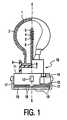
- Fig. 1shows an electric lamp used with the invention, a part of which is shown in side view, partly cut away, and another part of which is shown in cross-section.
- the electric lampcomprises a light-transmitting lamp vessel 1, for example made of glass, which is closed in a gastight manner and in which an electric element 2, being a (spiral-shaped) tungsten incandescent body with a center 4 in the Figure, is axially positioned on an axis 5 and is connected to current conductors 6 which issue from the lamp vessel to the exterior.
- the lamp shownhas a filling of an inert gas, for example an Ar/Ne mixture, with a filling pressure slightly above 5 bar.
- a lamp cap 10is firmly connected to the lamp vessel 1.
- the lamp cap 10has a synthetic resin housing 11.
- the housing 11comprises a flat base portion 7 which is at least substantially perpendicular to the axis 5.
- the lamp vessel 1is closed off in a gastight manner by means of a plate 8 of an insulating material, which plate lies in a plane which is at least substantially perpendicular to the axis 5.
- Electric element 2is mounted in a previously defined position with respect to the plate 8 during the manufacture of the lamp.
- the plate 8 of the lamp vessel 1is pressed home against the base portion by locking means 9, for example ridges, such that the electric element 2 will enter a previously defined position with respect to the reference means 12, for example studs.
- the studs 12form part of the lamp cap and are designed to abut against a support 30, for example a reflector, as is visible in Fig. 2.
- the lamp capalso comprises contact members 14 which are provided with a screen 13 and to which the current conductors 6 of the lamp vessel 1 are connected.
- the resilient action of the intermediate portionis obtained in that the intermediate portion is made so as to be hollow, so that no more than a wall remains as the intermediate portion, whereupon a major portion of the wall is removed by means of two grooves 18 which run perpendicularly to the axis 5.
- the remaining portion of the wallforms a bridge 19 which is rotated, near the next groove, through an angle of, for example, 180° about the axis 5.
- the lamp vessel 1 of the electric lamphas a relatively small axial dimension of approximately 22 mm and is suitable for consuming a relatively high power of, for example, 5 to 25 W.
- the electric lamphas a service life of approximately 6000 hours in this case.
- At least a part of the lamp vessel 1is covered with a light-absorbing coating 3 having an average thickness of 2-3 ⁇ m.
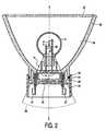
- Fig. 2shows the electric lamp provided with a support 30, being a reflector with a transparent plate 33 in the drawing, as well as with an adapter 25.
- the rubber ringseals off the opening 26 between the lamp cap and the reflector in a gastight manner.
- the adapteris provided with standardized contact points 27 which are passed through the bottom plate 28 of the adapter in a gastight manner and are connected to contact members 14 of the lamp cap 10.
- the lamp cap 10falls substantially entirely within a cone 36 which has its apex 35 in the center 4 of the electric element 2 and has an apex half angle ⁇ of 25°.
- the light originating from the electric element 2can reach the reflecting surface 34 substantially without obstruction and is reflected there at least substantially axially in the direction of the transparent plate 33.
- a quantity of 10 g ZnFe 2 O 4 (particle size 70 nm)is dispersed in a 50/50% water/ethanol mixture, using "disperbyk 190" as the dispersing agent.
- the overall weight of the mixtureis 30 g.
- a quantity of 3 g Fe 2 O 3(particle size 40 nm) is dispersed in a corresponding manner.
- a hydrolysis mixture of 40 g methyltrimethoxy silane (MTMS), 0.6 g tetraethylorthosilicate (TEOS), 32 g water, 4 g ethanol and 0.15 g glacial acetic acidis stirred for 48 hours at room temperature and, subsequently, stored in a refrigerator.
- a coating liquidis prepared by mixing 10 g of said ZnFe 2 O 4 dispersion, 6 g of the Fe 2 O 3 dispersion and 10 g of the MTMS/TEOS hydrolysis mixture with 4 g methoxy propanol, which coating liquid is subsequently spray coated onto the outer surface of the major part of a lamp vessel.
- the coatingis cured for 10 minutes at a temperature of 250°C. In this manner, a light-absorbing coating in a thickness up to 3 ⁇ m is obtained on a glass lamp vessel without crack formation during drying and curing.
- An electric lamp provided with a light-absorbing coating manufactured as described in this embodimentis amber-colored, transparent and free of light scattering.
- the color co-ordinate (x; y) in accordance with the definition of the C.I.E. 1931 color triangle diagramis (0.589; 0.405) at an overall transmission of 52% after the electric lamp has burned for 1 hour at 350 °C.
- the color point of the coatingis stable during the service life of the electric lamp.
- the coating obtained in accordance with the recipehas a thickness of 2.7 ⁇ m.
- the weight fraction of the components in this coatingis 52% ZnFe 2 O 4 and Fe 2 O 3 , 18% “disperbyk 190", and 30% MTMS.
- Fig. 3shows, in a part of a C.I.E. 1931 color triangle diagram, the color co-ordinates (x; y) of an electric lamp with a light-absorbing coating comprising the above-described mixture of ZnFe 2 O 4 and Fe 2 O 3 (indicated by means of circles in Fig. 3).
- the circle with the lowest x-coordinatecorresponds to a layer thickness of the ZnFe 2 O 4 /Fe 2 O 3 coating of approximately 2 ⁇ m.
- the circle with the highest x-coordinatecorresponds to a layer thickness of the ZnFe 2 O 4 /Fe 2 O 3 coating of approximately 3 ⁇ m.
- Fig. 3also shows two specified areas in the color triangle, wherein the color point of an electric lamp used as an amber-colored indicator for an automobile should be situated.
- the hatched area referenced S1corresponds to the European ECE standard for an amber-colored indicator
- the area referenced S2corresponds to the American SAE standard for an amber-colored indicator, which standards are both known to those skilled in the art.
- the light-absorbing coating obtained which is applied to an electric lampcan suitably be used as an amber-colored indicator and passes the Fakra test known to those skilled in the art.
- a quantity of 3 g BiVO 4is dispersed in a 50/50% water/ethanol mixture, using "solsperse 41090" as the dispersing agent.
- the overall weight of the mixtureis 23 g.
- a quantity of 3 g Fe 2 O 3is dispersed in a corresponding manner.
- a hydrolysis mixture of 40 g methyltrimethoxy silane (MTMS), 0.6 g tetraethyl orthosilicate (TEOS), 32 g water, 4 g ethanol and 0.15 g glacial acetic acidis stirred for 48 hours at room temperature and subsequently stored in a refrigerator.
- a coating liquidis prepared by mixing 10 g of said BiVO 4 dispersion, 6 g of the Fe 2 O 3 dispersion and 10 g of the MTMS/TEOS hydrolysis mixture with 4 g methoxy propanol, whereafter the coating liquid is spray coated onto the outer surface of the major part of a lamp vessel.
- the coatingis dried for 20 minutes at a temperature of 160°C. In this manner, a light-absorbing coating in a thickness up to 3 ⁇ m is formed on a glass lamp vessel without crack formation during drying and curing.
- An electric lamp provided with a light-absorbing coating made in accordance with the embodiment described hereinis amber-colored and relatively free of light scattering, although the diameter of the bismuth-vanadate particles exceeds 100 nm.
- the color co-ordinate (x; y) for a light-absorbing coating thus preparedamounts to (0.592; 0.101), in accordance with the definition of the C.I.E. 1931 color triangle diagram, at an overall transmission of 50%.
- the color point of the coatingremains stable during the service life of the electric lamp.
- the coating obtained in accordance with the recipehas a thickness of at least substantially 3 ⁇ m.
- the weight fraction of the components in this coatingis 21% Fe 2 O 3 , 21% BiVO 4 , 17% solspers and 41% MTMS.
- Fig. 3shows the color co-ordinates (x; y) of an electric lamp with a light-absorbing coating comprising the above-described mixture of BiVO 4 and Fe 2 O 3 (indicated by means of the squares in Fig. 3).
- the square with the lowest x-coordinatecorresponds to a layer thickness of the BiVO 4 /Fe 2 O 3 coating of approximately 2 ⁇ m.
- the square with the highest x-coordinatecorresponds to a layer thickness of the BiVO 4 /Fe 2 O 3 coating of approximately 3 ⁇ m.
- a quantity of 6 g P-doped Fe 2 O 3is dispersed in a 50/50% water/ethanol mixture, using "disperbyk 190" as the dispersing agent.
- the overall weight of the mixtureis 32 g.
- a hydrolysis mixture of 40 g methyltrimethoxy silane (MTMS), 0.6 g tetraethyl orthosilicate (TEOS), 32 g water, 4 g ethanol and 0.15 g glacial acetic acidis stirred for 48 hours at room temperature and subsequently stored in a refrigerator.
- a coatingis prepared by mixing 20 g of the P-doped Fe 2 O 3 dispersion and 7 g of the MTMS/TEOS hydrolysis mixture with 8 g methoxy propanol, and said coating liquid is subsequently spray coated onto the outer surface of the major part of a lamp vessel.
- the coatingis dried for 20 minutes at a temperature of 160 °C.
- a light-absorbing coatinghaving a thickness up to 6 ⁇ m is formed on a glass lamp vessel without crack formation during drying and curing.
- the realization of such a relatively large layer thicknessis possible because a relatively high concentration of pigment is applied at a relatively low concentration of MTMS.
- An electric lamp provided with a light-absorbing coating manufactured in accordance with the embodiment described hereinis red, transparent and free of light scattering.
- the color co-ordinate (x; y) for a light-absorbing coating thus preparedis (0.665; 0.335), in accordance with the definition of the C.I.E. 1931 color triangle diagram, at an overall transmission of approximately 20%.
- the color point of the coatingremains stable throughout the service life of the electric lamp.
- the color point of the electric lamp provided with a light-absorbing coating made in accordance with the embodiment described hereinlies within the specified areas for red brake light.
Landscapes
- Chemical & Material Sciences (AREA)
- Organic Chemistry (AREA)
- Life Sciences & Earth Sciences (AREA)
- Engineering & Computer Science (AREA)
- Chemical Kinetics & Catalysis (AREA)
- Materials Engineering (AREA)
- Composite Materials (AREA)
- General Chemical & Material Sciences (AREA)
- Geochemistry & Mineralogy (AREA)
- Inorganic Chemistry (AREA)
- Wood Science & Technology (AREA)
- Dispersion Chemistry (AREA)
- Vessels And Coating Films For Discharge Lamps (AREA)
- Paints Or Removers (AREA)
Abstract
Description
wherein at least a part of the lamp vessel is provided with a light-absorbingcoating,
wherein the light-absorbing coating includes a pigment which absorbs a part ofthe visible light.
the light-absorbing coating comprises a network which can be obtained byconversion of an organically modified silane by means of a sol-gel process,
said organically modified silane being selected from the group formed bycompounds of the following structural formula: RISi(ORII)3,
wherein RI comprises an alkyl group or an aryl group,
and wherein RII comprises an alkyl group.
methyltrimethoxy silane (MTMS), where RI = RII = CH3,
methyltriethoxy silane (MTES), where RI = CH3 and RII = C2H5,
phenyltrimethoxy silane (PTMS), where RI = C6H5 and RII = CH3, and
phenyltriethoxy silane (PTES), where RI = C6H5 and RII = C2H5. Such starting materials areknown per se and commercially available.
Claims (9)
- An electric lamp comprising a light-transmitting lamp vessel (1) whichaccommodates a light source (2),
wherein at least a part of the lamp vessel (2) is provided with a light-absorbingexterior coating (3),
wherein the light-absorbing coating (3) includes a pigment which absorbs apart of the visible light,
characterized in that
the light-absorbing coating (3) comprises a network of a sol-gel processed,converted, organically modified silane,
said organically modified silane being selected from the group formed bycompounds of the following structural formula: RISi(ORII)3,
wherein RI comprises an alkyl group or an aryl goup,
and wherein RII comprises an alkyl group. - An electric lamp as claimed in claim 1,characterized in that the RI groupcomprises CH3 or C6H5.
- An electric lamp as claimed in claim 1 or 2,characterized in that the RII groupcomprises CH3 or C2H5.
- An electric lamp as claimed in claim 1 or 2,characterized in that an averagediameter dp of the pigment is dp ≤ 100 nm.
- An electric lamp as claimed in claim 1 or 2,characterized in that the thicknesstc of the light-absorbing coating (3) is tc ≥ 1 µm.
- An electric lamp as claimed in claim 1 or 2,characterized in that silicaparticles having a diameter d ≤ 50 nm are incorporated in the network.
- An electric lamp as claimed in claim 1 or 2,characterized in that the pigmentis an inorganic pigment.
- An electric lamp as claimed in claim 7,characterized in that the pigment isselected from the group formed by iron oxide, iron oxide doped with phosphor, zinc-ironoxide, cobalt aluminate, neodymium oxide, bismuth vanadate, zirconium praseodymiumsilicate or mixtures thereof.
- An electric lamp as claimed in claim 8,characterized in that the pigment isformed by a mixture of iron oxide and bismuth vanadate or by a mixture of iron oxide dopedwith phosphor and bismuth vanadate.
Priority Applications (2)
| Application Number | Priority Date | Filing Date | Title |
|---|---|---|---|
| EP00964076AEP1129470B1 (en) | 1999-09-13 | 2000-08-31 | Electric lamp |
| EP05108281AEP1757565A3 (en) | 1999-09-13 | 2000-08-31 | Light-absorbing coating and electric lamp therewith |
Applications Claiming Priority (4)
| Application Number | Priority Date | Filing Date | Title |
|---|---|---|---|
| EP99202979 | 1999-09-13 | ||
| EP99202979 | 1999-09-13 | ||
| EP00964076AEP1129470B1 (en) | 1999-09-13 | 2000-08-31 | Electric lamp |
| PCT/EP2000/008502WO2001020641A1 (en) | 1999-09-13 | 2000-08-31 | Electric lamp |
Related Child Applications (2)
| Application Number | Title | Priority Date | Filing Date |
|---|---|---|---|
| EP05108281ADivisionEP1757565A3 (en) | 1999-09-13 | 2000-08-31 | Light-absorbing coating and electric lamp therewith |
| EP05108281.6Division-Into | 2005-09-09 |
Publications (2)
| Publication Number | Publication Date |
|---|---|
| EP1129470A1 EP1129470A1 (en) | 2001-09-05 |
| EP1129470B1true EP1129470B1 (en) | 2005-12-28 |
Family
ID=8240639
Family Applications (2)
| Application Number | Title | Priority Date | Filing Date |
|---|---|---|---|
| EP00964076AExpired - LifetimeEP1129470B1 (en) | 1999-09-13 | 2000-08-31 | Electric lamp |
| EP05108281AWithdrawnEP1757565A3 (en) | 1999-09-13 | 2000-08-31 | Light-absorbing coating and electric lamp therewith |
Family Applications After (1)
| Application Number | Title | Priority Date | Filing Date |
|---|---|---|---|
| EP05108281AWithdrawnEP1757565A3 (en) | 1999-09-13 | 2000-08-31 | Light-absorbing coating and electric lamp therewith |
Country Status (7)
| Country | Link |
|---|---|
| US (1) | US6819049B1 (en) |
| EP (2) | EP1129470B1 (en) |
| JP (1) | JP2003509825A (en) |
| KR (1) | KR100703248B1 (en) |
| CN (1) | CN100383910C (en) |
| DE (1) | DE60025153T2 (en) |
| WO (1) | WO2001020641A1 (en) |
Families Citing this family (33)
| Publication number | Priority date | Publication date | Assignee | Title |
|---|---|---|---|---|
| JP2003502449A (en) | 1999-06-10 | 2003-01-21 | ハネウエル・インターナシヨナル・インコーポレーテツド | Spin-on glass anti-reflective coating for photolithography |
| US6824879B2 (en) | 1999-06-10 | 2004-11-30 | Honeywell International Inc. | Spin-on-glass anti-reflective coatings for photolithography |
| KR20040039355A (en) | 2001-09-13 | 2004-05-10 | 코닌클리즈케 필립스 일렉트로닉스 엔.브이. | Electric lamp, lamp vessel provided with a light-absorbing coating as well as a method of preparing a light-absorbing coating |
| AU2002227106A1 (en) | 2001-11-15 | 2003-06-10 | Honeywell International Inc. | Spin-on anti-reflective coatings for photolithography |
| EP1472716A1 (en)* | 2002-01-24 | 2004-11-03 | Koninklijke Philips Electronics N.V. | Light-transmitting substrate provided with a light-absorbing coating |
| AU2003202752A1 (en) | 2002-02-22 | 2003-09-09 | Koninklijke Philips Electronics N.V. | Electric lamp |
| AU2003265074A1 (en)* | 2002-10-11 | 2004-05-04 | Koninklijke Philips Electronics N.V. | Light-transmitting substrate provided with a light-absorbing coating |
| CN1688517A (en)* | 2002-10-23 | 2005-10-26 | 皇家飞利浦电子股份有限公司 | Low-pressure mercury vapor discharge lamp |
| AU2003272016A1 (en)* | 2002-11-14 | 2004-06-03 | Koninklijke Philips Electronics N.V. | Light-transmitting substrate provided with a light-absorbing coating |
| US20060055331A1 (en) | 2002-11-14 | 2006-03-16 | Koninklijke Philips Electronics, N.V. | Light-transmitting substrate provided with a light-absorbing coating as well as a method of preparing a light-absorbing coating |
| WO2004053924A2 (en)* | 2002-12-10 | 2004-06-24 | Philips Intellectual Property & Standards Gmbh | Lamp for a vehicle headlight with low-beam function |
| JP2006515103A (en)* | 2002-12-17 | 2006-05-18 | コーニンクレッカ フィリップス エレクトロニクス エヌ ヴィ | High pressure discharge lamp |
| CN101128912A (en)* | 2003-11-06 | 2008-02-20 | 皇家飞利浦电子股份有限公司 | Lamp with light absorbing coating |
| US8053159B2 (en) | 2003-11-18 | 2011-11-08 | Honeywell International Inc. | Antireflective coatings for via fill and photolithography applications and methods of preparation thereof |
| DE102004043176B4 (en)* | 2004-09-03 | 2014-09-25 | Osram Gmbh | infrared Illuminator |
| JP4814242B2 (en)* | 2004-09-15 | 2011-11-16 | コーニンクレッカ フィリップス エレクトロニクス エヌ ヴィ | Light transmissive substrate provided with light absorbing coating, light absorbing coating, and method of making light absorbing coating |
| WO2006054212A2 (en)* | 2004-11-16 | 2006-05-26 | Koninklijke Philips Electronics N.V. | Coating for lamps and method for the preparation of such a coating |
| WO2006054227A2 (en)* | 2004-11-18 | 2006-05-26 | Koninklijke Philips Electronics N.V. | Coating for lamps and lamp at least partially provided with such a coating |
| TW200642841A (en)* | 2005-06-08 | 2006-12-16 | Nanoforce Technologies Corp | After glow lighting film having UV filtering and explosion-proof |
| KR101329547B1 (en) | 2005-08-22 | 2013-11-14 | 코닌클리케 필립스 엔.브이. | Cured coating for use in optics or electronics |
| WO2007130358A2 (en) | 2006-05-02 | 2007-11-15 | Superbulbs, Inc. | Plastic led bulb |
| CA2645231A1 (en) | 2006-05-02 | 2007-11-15 | Superbulbs, Inc. | Heat removal design for led bulbs |
| WO2007130357A2 (en) | 2006-05-02 | 2007-11-15 | Superbulbs, Inc. | Method of light dispersion and preferential scattering of certain wavelengths of light for light-emitting diodes and bulbs constructed therefrom |
| US8642246B2 (en) | 2007-02-26 | 2014-02-04 | Honeywell International Inc. | Compositions, coatings and films for tri-layer patterning applications and methods of preparation thereof |
| US8439528B2 (en) | 2007-10-03 | 2013-05-14 | Switch Bulb Company, Inc. | Glass LED light bulbs |
| JP2011501464A (en) | 2007-10-24 | 2011-01-06 | テオス・インコーポレイテッド | Diffuser for LED light source |
| US8557877B2 (en) | 2009-06-10 | 2013-10-15 | Honeywell International Inc. | Anti-reflective coatings for optically transparent substrates |
| US8864898B2 (en) | 2011-05-31 | 2014-10-21 | Honeywell International Inc. | Coating formulations for optical elements |
| DE102011050872A1 (en)* | 2011-06-06 | 2012-12-06 | Inomat Gmbh | Semitransparent coating material |
| US8591069B2 (en) | 2011-09-21 | 2013-11-26 | Switch Bulb Company, Inc. | LED light bulb with controlled color distribution using quantum dots |
| US20140333203A1 (en)* | 2011-12-12 | 2014-11-13 | Koninklijke Philips N.V. | Red emitting phosphor for plasma display panels and gas discharge lamps |
| CN104487515B (en)* | 2012-07-11 | 2016-08-24 | 皇家飞利浦有限公司 | Silicone product, the lighting unit including silicone product and the method manufacturing silicone product |
| JP6803842B2 (en) | 2015-04-13 | 2020-12-23 | ハネウェル・インターナショナル・インコーポレーテッドHoneywell International Inc. | Polysiloxane formulations and coatings for optoelectronic applications |
Family Cites Families (15)
| Publication number | Priority date | Publication date | Assignee | Title |
|---|---|---|---|---|
| CA766196A (en) | 1967-08-29 | C. Gainer Gordon | Lamp coating | |
| US3351409A (en)* | 1963-06-12 | 1967-11-07 | Irvin H Mcguire | Light diffusion material, method of making and using same |
| DE3827451C1 (en)* | 1988-08-12 | 1989-10-12 | Philips Patentverwaltung Gmbh, 2000 Hamburg, De | |
| EP0533325B1 (en)* | 1991-07-25 | 1996-01-10 | Hamamatsu Photonics K.K. | Discharge tube |
| US5503935A (en)* | 1992-05-11 | 1996-04-02 | General Electric Company | Heat curable primerless silicone hardcoat compositions, and thermoplastic composites |
| EP0675908B1 (en)* | 1993-07-06 | 1997-10-15 | Koninklijke Philips Electronics N.V. | Method of preparing a composite material comprising a silica network and chains of a polyhydroxy compound and a liquid crystal display device having a top coat of such material |
| US5520952A (en)* | 1993-07-16 | 1996-05-28 | Tokyo Ohka Kogyo Co., Ltd. | Method for forming a protective coating film on electronic parts and devices |
| US5578892A (en)* | 1995-03-13 | 1996-11-26 | General Electric Company | Bug free linear quartz halogen lamp |
| JP3516543B2 (en)* | 1995-10-27 | 2004-04-05 | 株式会社小糸製作所 | Colored coating agent for turn signal lamp and turn signal lamp |
| JP3318667B2 (en)* | 1996-02-06 | 2002-08-26 | シャープ株式会社 | Liquid crystal display |
| JPH10212138A (en)* | 1997-01-27 | 1998-08-11 | Sumitomo Osaka Cement Co Ltd | Display device |
| JPH10268678A (en)* | 1997-03-26 | 1998-10-09 | Sumitomo Electric Ind Ltd | Fixing belt and method of manufacturing the same |
| EP0874278A1 (en)* | 1997-04-23 | 1998-10-28 | Agfa-Gevaert N.V. | Improved passivation layer on top of a colour filter array for use in a liquid crystal device |
| US6129980A (en)* | 1997-07-11 | 2000-10-10 | Fuji Photo Film Co., Ltd. | Anti-reflection film and display device having the same |
| US5863321A (en)* | 1998-02-25 | 1999-01-26 | Basf Corporation | Straight-shade coating compositions |
- 2000
- 2000-08-31EPEP00964076Apatent/EP1129470B1/ennot_activeExpired - Lifetime
- 2000-08-31CNCNB008019525Apatent/CN100383910C/ennot_activeExpired - Lifetime
- 2000-08-31WOPCT/EP2000/008502patent/WO2001020641A1/enactiveIP Right Grant
- 2000-08-31EPEP05108281Apatent/EP1757565A3/ennot_activeWithdrawn
- 2000-08-31JPJP2001524126Apatent/JP2003509825A/enactivePending
- 2000-08-31KRKR1020017005901Apatent/KR100703248B1/ennot_activeExpired - Lifetime
- 2000-08-31DEDE60025153Tpatent/DE60025153T2/ennot_activeExpired - Lifetime
- 2000-09-07USUS09/656,987patent/US6819049B1/ennot_activeExpired - Lifetime
Also Published As
| Publication number | Publication date |
|---|---|
| KR100703248B1 (en) | 2007-04-03 |
| EP1757565A3 (en) | 2009-01-07 |
| DE60025153T2 (en) | 2006-08-31 |
| DE60025153D1 (en) | 2006-02-02 |
| US6819049B1 (en) | 2004-11-16 |
| JP2003509825A (en) | 2003-03-11 |
| CN1321329A (en) | 2001-11-07 |
| WO2001020641A1 (en) | 2001-03-22 |
| EP1129470A1 (en) | 2001-09-05 |
| CN100383910C (en) | 2008-04-23 |
| EP1757565A2 (en) | 2007-02-28 |
| KR20010080983A (en) | 2001-08-25 |
Similar Documents
| Publication | Publication Date | Title |
|---|---|---|
| EP1129470B1 (en) | Electric lamp | |
| US7740900B2 (en) | Method of preparing a light-absorbing coating | |
| EP1196942B1 (en) | Electric lamp comprising a light absorbing medium | |
| US20060017366A1 (en) | Low-pressure mercury vapor discharge lamp | |
| US7804249B2 (en) | Light-transmitting substrate provided with a light-absorbing coating, light absorbing coating as well as method of preparing a light-absorbing coating | |
| KR100430137B1 (en) | Coloring coating agent and colored bulb | |
| US6520664B1 (en) | Pigment coated lamp and luminaire emitting colored light | |
| US20060055331A1 (en) | Light-transmitting substrate provided with a light-absorbing coating as well as a method of preparing a light-absorbing coating | |
| US8999467B2 (en) | Cured coating for use in optics or electronics | |
| EP1782453B1 (en) | Electric lamp comprising a light absorbing medium | |
| WO2004044486A2 (en) | Light-transmitting substrate provided with a light-absorbing coating | |
| WO2006054227A2 (en) | Coating for lamps and lamp at least partially provided with such a coating | |
| WO2006054212A2 (en) | Coating for lamps and method for the preparation of such a coating |
Legal Events
| Date | Code | Title | Description |
|---|---|---|---|
| PUAI | Public reference made under article 153(3) epc to a published international application that has entered the european phase | Free format text:ORIGINAL CODE: 0009012 | |
| AK | Designated contracting states | Kind code of ref document:A1 Designated state(s):AT BE CH CY DE DK ES FI FR GB GR IE IT LI LU MC NL PT SE | |
| 17P | Request for examination filed | Effective date:20010924 | |
| RBV | Designated contracting states (corrected) | Designated state(s):DE FR GB IT | |
| GRAP | Despatch of communication of intention to grant a patent | Free format text:ORIGINAL CODE: EPIDOSNIGR1 | |
| GRAS | Grant fee paid | Free format text:ORIGINAL CODE: EPIDOSNIGR3 | |
| GRAA | (expected) grant | Free format text:ORIGINAL CODE: 0009210 | |
| AK | Designated contracting states | Kind code of ref document:B1 Designated state(s):DE FR GB IT | |
| REG | Reference to a national code | Ref country code:GB Ref legal event code:FG4D | |
| REF | Corresponds to: | Ref document number:60025153 Country of ref document:DE Date of ref document:20060202 Kind code of ref document:P | |
| ET | Fr: translation filed | ||
| PLBE | No opposition filed within time limit | Free format text:ORIGINAL CODE: 0009261 | |
| STAA | Information on the status of an ep patent application or granted ep patent | Free format text:STATUS: NO OPPOSITION FILED WITHIN TIME LIMIT | |
| 26N | No opposition filed | Effective date:20060929 | |
| REG | Reference to a national code | Ref country code:DE Ref legal event code:R082 Ref document number:60025153 Country of ref document:DE Representative=s name:VOLMER, GEORG, DIPL.-ING., DE | |
| REG | Reference to a national code | Ref country code:DE Ref legal event code:R082 Ref document number:60025153 Country of ref document:DE Representative=s name:VOLMER, GEORG, DIPL.-ING., DE Effective date:20140328 Ref country code:DE Ref legal event code:R081 Ref document number:60025153 Country of ref document:DE Owner name:KONINKLIJKE PHILIPS N.V., NL Free format text:FORMER OWNER: KONINKLIJKE PHILIPS ELECTRONICS N.V., EINDHOVEN, NL Effective date:20140328 Ref country code:DE Ref legal event code:R082 Ref document number:60025153 Country of ref document:DE Representative=s name:MEISSNER, BOLTE & PARTNER GBR, DE Effective date:20140328 Ref country code:DE Ref legal event code:R082 Ref document number:60025153 Country of ref document:DE Representative=s name:MEISSNER BOLTE PATENTANWAELTE RECHTSANWAELTE P, DE Effective date:20140328 | |
| REG | Reference to a national code | Ref country code:FR Ref legal event code:CA Effective date:20141126 Ref country code:FR Ref legal event code:CD Owner name:KONINKLIJKE PHILIPS N.V., NL Effective date:20141126 | |
| REG | Reference to a national code | Ref country code:DE Ref legal event code:R082 Ref document number:60025153 Country of ref document:DE Representative=s name:MEISSNER, BOLTE & PARTNER GBR, DE Ref country code:DE Ref legal event code:R082 Ref document number:60025153 Country of ref document:DE Representative=s name:MEISSNER BOLTE PATENTANWAELTE RECHTSANWAELTE P, DE | |
| REG | Reference to a national code | Ref country code:FR Ref legal event code:PLFP Year of fee payment:17 | |
| REG | Reference to a national code | Ref country code:FR Ref legal event code:PLFP Year of fee payment:18 | |
| REG | Reference to a national code | Ref country code:FR Ref legal event code:CA Effective date:20180710 Ref country code:FR Ref legal event code:TP Owner name:LUMILEDS HOLDING B.V., NL Effective date:20180710 | |
| REG | Reference to a national code | Ref country code:FR Ref legal event code:PLFP Year of fee payment:19 | |
| REG | Reference to a national code | Ref country code:GB Ref legal event code:732E Free format text:REGISTERED BETWEEN 20180920 AND 20180926 | |
| REG | Reference to a national code | Ref country code:DE Ref legal event code:R082 Ref document number:60025153 Country of ref document:DE Ref country code:DE Ref legal event code:R081 Ref document number:60025153 Country of ref document:DE Owner name:LUMILEDS HOLDING B.V., NL Free format text:FORMER OWNER: KONINKLIJKE PHILIPS N.V., EINDHOVEN, NL | |
| PGFP | Annual fee paid to national office [announced via postgrant information from national office to epo] | Ref country code:FR Payment date:20190827 Year of fee payment:20 Ref country code:IT Payment date:20190822 Year of fee payment:20 | |
| PGFP | Annual fee paid to national office [announced via postgrant information from national office to epo] | Ref country code:GB Payment date:20190829 Year of fee payment:20 | |
| PGFP | Annual fee paid to national office [announced via postgrant information from national office to epo] | Ref country code:DE Payment date:20191031 Year of fee payment:20 | |
| REG | Reference to a national code | Ref country code:DE Ref legal event code:R071 Ref document number:60025153 Country of ref document:DE | |
| REG | Reference to a national code | Ref country code:GB Ref legal event code:PE20 Expiry date:20200830 | |
| PG25 | Lapsed in a contracting state [announced via postgrant information from national office to epo] | Ref country code:GB Free format text:LAPSE BECAUSE OF EXPIRATION OF PROTECTION Effective date:20200830 |