EP1128870B1 - Transdermal drug delivery and analyte extraction - Google Patents
Transdermal drug delivery and analyte extractionDownload PDFInfo
- Publication number
- EP1128870B1 EP1128870B1EP99952784.9AEP99952784AEP1128870B1EP 1128870 B1EP1128870 B1EP 1128870B1EP 99952784 AEP99952784 AEP 99952784AEP 1128870 B1EP1128870 B1EP 1128870B1
- Authority
- EP
- European Patent Office
- Prior art keywords
- current
- electrodes
- power source
- skin
- stratum corneum
- Prior art date
- Legal status (The legal status is an assumption and is not a legal conclusion. Google has not performed a legal analysis and makes no representation as to the accuracy of the status listed.)
- Expired - Lifetime
Links
- 239000012491analyteSubstances0.000titledescription14
- 238000000605extractionMethods0.000titledescription9
- 238000013271transdermal drug deliveryMethods0.000titledescription7
- 210000003491skinAnatomy0.000claimsdescription118
- 210000000434stratum corneumAnatomy0.000claimsdescription106
- 239000000126substanceSubstances0.000claimsdescription48
- 238000002679ablationMethods0.000claimsdescription31
- 230000005684electric fieldEffects0.000claimsdescription25
- 239000003990capacitorSubstances0.000claimsdescription22
- 239000008151electrolyte solutionSubstances0.000claimsdescription20
- 230000002829reductive effectEffects0.000claimsdescription15
- 238000005259measurementMethods0.000claimsdescription11
- 230000010363phase shiftEffects0.000claimsdescription11
- 239000000853adhesiveSubstances0.000claimsdescription5
- 230000001070adhesive effectEffects0.000claimsdescription5
- 210000001519tissueAnatomy0.000description22
- 238000000034methodMethods0.000description21
- 239000013543active substanceSubstances0.000description20
- 230000015556catabolic processEffects0.000description13
- 230000015572biosynthetic processEffects0.000description11
- 239000007933dermal patchSubstances0.000description11
- 230000006870functionEffects0.000description10
- 230000007423decreaseEffects0.000description8
- 239000003792electrolyteSubstances0.000description8
- 238000004520electroporationMethods0.000description8
- 239000000463materialSubstances0.000description7
- 239000011148porous materialSubstances0.000description7
- 239000004020conductorSubstances0.000description6
- 238000009792diffusion processMethods0.000description6
- 239000003814drugSubstances0.000description6
- 229940079593drugDrugs0.000description6
- 230000001965increasing effectEffects0.000description6
- 150000002605large moleculesChemical class0.000description6
- 229920002521macromoleculePolymers0.000description6
- 230000037317transdermal deliveryEffects0.000description6
- 210000002615epidermisAnatomy0.000description5
- 238000012544monitoring processMethods0.000description5
- 230000008569processEffects0.000description5
- 230000035807sensationEffects0.000description5
- 239000000758substrateSubstances0.000description5
- 230000008859changeEffects0.000description4
- 210000004207dermisAnatomy0.000description4
- 230000035699permeabilityEffects0.000description4
- 238000012546transferMethods0.000description4
- 230000003247decreasing effectEffects0.000description3
- 238000012377drug deliveryMethods0.000description3
- 230000000694effectsEffects0.000description3
- 238000010438heat treatmentMethods0.000description3
- 238000004519manufacturing processMethods0.000description3
- 230000021715photosynthesis, light harvestingEffects0.000description3
- BQCADISMDOOEFD-UHFFFAOYSA-NSilverChemical compound[Ag]BQCADISMDOOEFD-UHFFFAOYSA-N0.000description2
- 238000007600chargingMethods0.000description2
- 230000001276controlling effectEffects0.000description2
- 230000008878couplingEffects0.000description2
- 238000010168coupling processMethods0.000description2
- 238000005859coupling reactionMethods0.000description2
- 239000006071creamSubstances0.000description2
- 238000005868electrolysis reactionMethods0.000description2
- 238000004146energy storageMethods0.000description2
- 230000008713feedback mechanismEffects0.000description2
- 239000000835fiberSubstances0.000description2
- 230000004927fusionEffects0.000description2
- 230000000670limiting effectEffects0.000description2
- 239000000203mixtureSubstances0.000description2
- 239000002245particleSubstances0.000description2
- 230000037361pathwayEffects0.000description2
- 238000010791quenchingMethods0.000description2
- 230000001105regulatory effectEffects0.000description2
- 238000000926separation methodMethods0.000description2
- 229910052709silverInorganic materials0.000description2
- 239000004332silverSubstances0.000description2
- 231100000075skin burnToxicity0.000description2
- 150000003384small moleculesChemical class0.000description2
- WHXSMMKQMYFTQS-UHFFFAOYSA-NLithiumChemical compound[Li]WHXSMMKQMYFTQS-UHFFFAOYSA-N0.000description1
- 230000000712assemblyEffects0.000description1
- 238000000429assemblyMethods0.000description1
- 238000010276constructionMethods0.000description1
- 230000005611electricityEffects0.000description1
- 239000000839emulsionSubstances0.000description1
- 230000002708enhancing effectEffects0.000description1
- 238000002474experimental methodMethods0.000description1
- 239000002657fibrous materialSubstances0.000description1
- 230000004907fluxEffects0.000description1
- 230000001939inductive effectEffects0.000description1
- 208000014674injuryDiseases0.000description1
- 239000012212insulatorSubstances0.000description1
- 230000002427irreversible effectEffects0.000description1
- 150000002632lipidsChemical class0.000description1
- 229910052744lithiumInorganic materials0.000description1
- 239000011159matrix materialSubstances0.000description1
- 230000008058pain sensationEffects0.000description1
- 230000035515penetrationEffects0.000description1
- 239000000825pharmaceutical preparationSubstances0.000description1
- 229940127557pharmaceutical productDrugs0.000description1
- 230000001681protective effectEffects0.000description1
- 238000010278pulse chargingMethods0.000description1
- 230000002441reversible effectEffects0.000description1
- 239000000523sampleSubstances0.000description1
- 229910052710siliconInorganic materials0.000description1
- 239000010703siliconSubstances0.000description1
- 230000000638stimulationEffects0.000description1
- 238000012360testing methodMethods0.000description1
- 230000008733traumaEffects0.000description1
Images


Classifications
- A—HUMAN NECESSITIES
- A61—MEDICAL OR VETERINARY SCIENCE; HYGIENE
- A61N—ELECTROTHERAPY; MAGNETOTHERAPY; RADIATION THERAPY; ULTRASOUND THERAPY
- A61N1/00—Electrotherapy; Circuits therefor
- A61N1/18—Applying electric currents by contact electrodes
- A61N1/32—Applying electric currents by contact electrodes alternating or intermittent currents
- A61N1/327—Applying electric currents by contact electrodes alternating or intermittent currents for enhancing the absorption properties of tissue, e.g. by electroporation
- A—HUMAN NECESSITIES
- A61—MEDICAL OR VETERINARY SCIENCE; HYGIENE
- A61N—ELECTROTHERAPY; MAGNETOTHERAPY; RADIATION THERAPY; ULTRASOUND THERAPY
- A61N1/00—Electrotherapy; Circuits therefor
- A61N1/18—Applying electric currents by contact electrodes
- A61N1/20—Applying electric currents by contact electrodes continuous direct currents
- A61N1/30—Apparatus for iontophoresis, i.e. transfer of media in ionic state by an electromotoric force into the body, or cataphoresis
- A—HUMAN NECESSITIES
- A61—MEDICAL OR VETERINARY SCIENCE; HYGIENE
- A61N—ELECTROTHERAPY; MAGNETOTHERAPY; RADIATION THERAPY; ULTRASOUND THERAPY
- A61N1/00—Electrotherapy; Circuits therefor
- A61N1/18—Applying electric currents by contact electrodes
- A61N1/32—Applying electric currents by contact electrodes alternating or intermittent currents
- A61N1/325—Applying electric currents by contact electrodes alternating or intermittent currents for iontophoresis, i.e. transfer of media in ionic state by an electromotoric force into the body
Definitions
- the present inventionrelates generally to devices for drug delivery and analyte extraction, and specifically to devices for puncturing the outer layer of living skin and to devices for transdermal drug delivery any analyte extraction.
- transdermal drug delivery and/or analyte extractionincluding passive diffusion of a drug or analyte between a Skin patch and skin, as well as active processes such as iontophoresis, sonophoresis, electroporation, and chemically enhanced diffusion. These methods are primarily used for generating transdermal movement of small molecules, but generally do not enhance the motion of large molecules through the 10-50 micron thick outermost layer of the skin, the stratum corneum epidermidis.
- PCT Publication WO 97/07734also discloses thermal ablation of the stratum corneum using an electrically resistive element in contract with the stratum corneum, such that a high current through the element causes a general heating of tissue in its vicinity, most particularly the stratum corneum. As above, no means are disclosed to terminate current flow upon sufficient disruption of the stratum corneum. Additionally, thermal characteristics of skin vary highly across different areas of an individual's skin, as well as among a group of subjects, making optimal thermal dosages, which produce the desired ablation without causing pain very difficult to determine.
- Electroporationis also well known in the art as a method to increase pore size by application of an electric field. This process is described in an article by Chizmadzhev et al., entitled “Electrical properties of skin at moderate voltages,” Biophysics Journal, February, 1998, 74(2), pp. 843-856 . Electroporation is disclosed as a means for transiently decreasing the electrical resistance of the stratum corneum and increasing the transdermal flux of small molecules by applying an electric field to increase the size of existing pores. Electroporation generally does not produce pores of sufficient diameter to pass large molecules therethrough. Additionally, optimal voltage profiles are difficult to determine because of naturally occurring variations as described hereinabove, as well as the lack of an accurate feedback mechanism to indicate achievement of the desired pore enlargement. If excessive voltage is applied, an irreversible breakdown occurs, resulting in damage to the skin and possible sensations of pain.
- a device for enhancing transdermal movement of a substancecomprising: (a) a skin patch, with at least two electrodes in contact with the skin of a subject; and (b) a control unit, coupled to the patch, which causes a current to pass between the electrodes through the stratum corneum epidermidis, in order to generate at least one micro-channel in the stratum corneum to enable or augment transdermal movement of the substance.
- the control unitcomprises switching circuitry to control the magnitude and/or duration of the electric field at the electrode.
- micro-channelrefers to a pathway generally extending from the surface of the skin through all or a significant part of the stratum corneum, through which pathway molecules can diffuse.
- micro-channelsallow the diffusion therethrough of large molecules at a greater rate than the same molecules would diffuse through pores generated by electroporation. It is believed that such micro-channels are formed due to local power dissipation leading to ablation of the stratum corneum when an electric field of sufficient magnitude is applied to a small area of the skin, in contact with the electrodes, for a certain period of time.
- the present inventionenables relatively large channels to be formed, through which even large molecules of the active substance can pass rapidly, without the necessity of ionizing or polarizing the molecules.
- the current flow between the electrodescan be described as having two componens:
- apparatusesare employed to increase the relative value of the lateral component with respect to the perpendicular component.
- stratum corneum epidermidisthe-superficial layer of the epidermis
- limiting current flow substantially to the non-innervated stratum corneumis expected to decrease or eliminate the subject's sensations, discomfort, or pain responsive to use of the present invention, particularly as compared with other procedures known in the art.
- a voltage applied between two electrodes on the skingenerates an electric field that is to a large extent confined to the volume in a vicinity of the electrodes.
- electrodes which are widely spacedproduce a field -- and current flow responsive thereto - which extends relatively deep into the skin.
- electrodes which are closely spaceddo not generate significant current flow at deeper layers. Therefore, in some preferred embodiments of the present invention, the electrodes of the device are separated by distances smaller than about 100 microns (but for some applications by distances of up to approximately 500 microns), in order to generate a current flow which is largely confined to a thin layer, comprising most or all of the stratum corneum. This effectively results in a desired larger value of the ratio of the lateral component to the perpendicular component, as described hereinabove.
- a high-frequency AC current with an optional DC current added theretois applied between the closely-spaced electrodes in order to generate lateral capacitive currents in the stratum corneum and to cause breakdown and micro-channel formation in the stratum corneum.
- the patchcomprises an array of electrodes, preferably closely-spaced electrodes, which act together to produce a high micro-channel density in an area of the skin under the patch.
- the control unit and/or associated circuitrysequentially or simultaneously evaluates the current flow through each electrode, or a subset of the electrodes, in order to determine when one or more micro-channels have formed responsive to the applied field. Responsive thereto, the control unit discontinues application of the field. Since the formation of a micro-channel is typically marked by a local drop in electrical resistance of the skin, the control unit may, for example, reduce the voltage or current applied at any electrode wherein the current has exceeded a threshold. By reducing -current flow upon or shortly after micro-channel formation, the likelihood of skin burns or pain sensations is minimized.
- a relatively high voltageis applied to the electrodes initially, so as to induce formation of micro-channels through the skin.
- a property of the current flowis detected, and the current is reduced or terminated when the property reaches a predetermined threshold.
- the detected property of the current flowis secondary to changes in a conduction property of the skin, responsive to formation of one or more micro-channels through the stratum corneum.
- a time-varying voltage V(t)V0 + k*(t ⁇ n)
- V(t)V0 + k*(t ⁇ n)
- V(t)V0 + k*(t ⁇ n)
- V(t)V0 + k*(t ⁇ n)
- V(t)V0 + k*(t ⁇ n)
- V(t)V0 + k*(t ⁇ n)
- V(t)V0 + k*(t ⁇ n
- Comparisons of I and/or Integral[I(t)dt] and/or dI/dt and/or d 2 I/dt 2 with respective threshold valuesare used as indicators of micro-channel formation and/or to determine when to generate the shut-off signal for the electrodes.
- control unitpreferably calculates changes in a phase shift between V(t) and I(t) during application of the electric field, and controls the field responsive to these changes. It is believed that cells in the stratum corneum demonstrate capacitance, which causes the phase shift, and that ablation of the stratum corneum decreases the capacitance and is evidenced by a decrease in the phase shift.
- the total charge which is passed through the skinis limited by a capacitor, inductor, or other energy-storage device.
- An appropriate choice of values for these componentssets an absolute maximum quantity of charge which can pass through the skin, and thus limits any damage that can be caused thereby.
- one or more of the electrodescomprise or are coupled to an electrically conductive dissolving element, where the dissolving rate is generally proportional to the current passing through the electrode.
- the electrodeceases to conduct electricity.
- a maximum total charge, Q totalis associated with an electrode, such that current flows through the element for only as long as q(t), defined as Integral[I(t)dt], is less than Q total .
- the dissolving elementis constructed so that it becomes non-conductive after a quantity of charge has passed therethrough which is sufficient to ablate the stratum corneum.
- the electrodesare "printed" directly on the skin, preferably by stamping or by employing a transfer patch of a conductive substance (such as, for example, a conductive ink containing silver grains).
- a conductive substancesuch as, for example, a conductive ink containing silver grains.
- the conductive substancepreferably comprises a matrix holding the drug to be administered to a subject.
- the printed electrodesdemonstrate a substantially complete loss of conductance therethrough upon ablation of the stratum corneum responsive to the applied electric field.
- each printed electrodecomprises a material which is conductive only when current flowing therethrough remains below a threshold value. If the current exceeds the threshold, then thermal fusion of the material causes it to become largely nonconductive, i.e. the material acts as a fuse. Still further preferably, current continues to flow through the other electrodes until they reach the threshold current, at a time which is generally associated with the time required for ablation of the stratum corneum, as described hereinabove.
- the control unitmay be made substantially simpler than as described regarding other embodiments, and generally does not need other circuitry in order to determine whether to generate a shut-off signal.
- two electrodes on the patchform a concentric electrode pair, in which an inner electrode generates a current which passes through the stratum corneum to an outer electrode surrounding the inner electrode.
- the distance between the inner and outer electrodesis preferably between about 50 and about 200 microns, in order to maintain the ratio of the lateral to the perpendicular component of the current at a high value, as described hereinabove.
- a conductance-enhancing substancepreferably comprising a conductive cream or ink
- the conductance-enhancing substancecomprises a composition with a high diffusion coefficient, which diffuses into the lipid layers of the stratum corneum and further augments the selective power dissipation-therein, in order to ablate the stratum corneum with substantially little damage to the underlying tissue.
- the substancehas an electrical charge associated therewith, such that when a small lateral field is applied, lateral diffusion of the substance within the stratum corneum is enhanced (i.e., iontophoresis of the substance).
- the substancefurther comprises an active substance, for example, a pharmaceutical product, dissolved or mixed therein.
- an active substancefor example, a pharmaceutical product, dissolved or mixed therein.
- the control unitcomprises one or more clusters of electrodes, in which monitoring and control are performed for each cluster rather than for the individual electrodes therein.
- the clusteris preferably over a relatively small area of skin, for example, from about 1 mm 2 to about 100 mm 2 , in which properties of the skin are assumed to be substantially constant.
- the deviceis a stand-alone device, which enables transdermal delivery of an active substance or enhances transdermal motion of an analyte.
- the devicecreates micro-channels as described hereinabove and is then removed from the skin, in order to enhance the transdermal delivery of a substance into or out of a commercially-available skin patch subsequently placed on the skin.
- the deviceis an add-on to commercially available transdermal drug delivery/analyte extraction devices, and serves primarily to create the micro-channels in the stratum corneum, and optionally to act as a vehicle through which the substance may pass.
- US-A-5681282discloses an electrosurgical probe comprising an electrode array disposed over a recessed surface near a distal end of a shaft.
- the arrayincludes a plurality of electrically isolated electrode terminals having substantially the same potential.
- a connectoris disposed at a proximal end of the shaft for electrically coupling the electrode terminals to a high frequency voltage source.
- WO-A-97/16222discloses a device for transdermal molecular delivery comprising molecules to be delivered mixed with particles, contacting a selected area of a skin surface with the particles and molecules, applying a pulsed electric field of sufficient amplitude and duration to induce dielectric breakdown of the stratum corneum, and applying a pressure to the molecules to force transport of the molecules through the pores in the stratum corneum into the underlying skin.
- the inventionprovides a device in accordance with claim 1 bellow.
- a device for thermally ablating stratum corneum epidermidis of skin on the body of a subjectcomprising:
- skin layers beneath the stratum corneumare substantially not ablated.
- the ablation of the stratum corneumcauses a puncturing thereof.
- the substanceincludes a drug that is delivered through the skin.
- the substanceincludes an analyte that is extracted through the skin.
- the power sourcegenerates an electric field which causes a current to flow through the stratum corneum
- the devicereduces power dissipated in the stratum corneum responsive to variation of a characteristic of the current.
- the characteristicis drawn from a list consisting of: the magnitude of the current; a time-integration of the current; a first time-derivative of the current; and a second time-derivative of the current
- current through one of the plurality of electrodesis reduced substantially independently of the current through another one of the plurality of electrodes.
- At least one of the plurality of electrodesis coupled to receive the current through a limited-conduction unit, which unit allows current below a threshold value to flow therethrough substantially unimpeded, and becomes substantially non-conductive if the current flowing therethrough exceeds a limited-conduction threshold value.
- At least one of the plurality of electrodesis coupled to an electrically-conductive dissolving element characterized by a dissolving rate generally proportional to the current passing therethrough, which becomes substantially nonconductive responsive to a function of the current.
- the functionincludes a time integral of the current having passed through the dissolving element.
- the dissolving elementincludes:
- the dissolving elementalso includes a second node, immersed in the electrolyte solution, wherein the power source generates alternating current, and wherein the device further includes:
- the dissolving elementincludes:
- the current through at least one of the plurality of electrodesis reduced responsive to the variation of the characteristic of the current through another one of the plurality of electrodes.
- the devicealso includes a voltage sensing unit coupled to measure a voltage drop across two of the plurality of electrodes, and current from the power source is reduced responsive to the measurement made by the sensing unit.
- the power sourceincludes a current source, and current from the current source is reduced responsive to a measurement made by the sensing unit which indicates that the electrical potential between the two electrodes is below a voltage-threshold value.
- the deviceincludes a resistive element coupled to one of the two electrodes and to the power source, and the voltage sensing unit is further coupled to measure a voltage drop across the resistive element in order to determine a current passing therethrough.
- the power sourceincludes an alternating current source, such that the measurements of the voltage drop across the two electrodes and the current through the resistive element determine a phase shift. The current from the alternating current source is reduced responsive to the phase shift being below a threshold value.
- the deviceincludes:
- the power sourceincludes a voltage source, and the voltage is reduced responsive to a measurement made by the sensing unit which indicates that the current through the resistive element is above a current-threshold value.
- At least one of the plurality of electrodesis printed directly on the skin and becomes substantially electrically nonconductive responsive to the value of the current passing therethrough being greater than a threshold value.
- the deviceincludes:
- the power sourcecharges the capacitor during the closed phase, and the capacitor discharges current through the electrodes during the open phase.
- the distance between two of the plurality of electrodesis less than about 0.3 mm. Further preferably, the distance between two of the plurality of electrodes is between about 0.01 mm and about 0.1 mm.
- the plurality of electrodesinclude:
- the power sourcegenerates alternating current, a frequency thereof being above about 100 Hz.
- the frequencyis between about 1 kHz and about 300 kHz.
- the power sourcemodulates a frequency of the alternating current between a first frequency value and a second frequency value.
- a device for passing electrical current through the skin of a subjectincluding:
- a method for ablating the stratum corneum epidermidis of a subjectincluding:
- Skin layers beneath the stratum corneumare substantially not ablated.
- applying the electrical energyincludes puncturing the skin.
- Applying the energyincludes ablating the area of the stratum corneum in order to allow a substance to pass through the area. Further, the method includes delivering a drug or extracting an analyte through the area.
- Applying electrical energyincludes:
- the characteristicis drawn from a list consisting of: a magnitude of the current; a time-integration of the current; a first time-derivative of the current; and a second time-derivative of the current.
- causing the current to flowincludes passing current to the one or more points on the skin through one or more respective limited-conduction units, wherein the units allow current below a threshold value to flow therethrough substantially unimpeded. and wherein the units become substantially nonconductive if the current flowing therethrough exceeds a limited-conduction threshold value.
- causing the current to flowincludes passing current to the one or more points on the skin through one or more respective electrically conductive dissolving elements, each element characterized by a dissolving rate generally proportional to the current passing therethrough, and each element becoming substantially nonconductive when the total charge having passed therethrough exceeds a dissolving element threshold value.
- reducing the current flowincludes reducing the current at one of the respective points substantially independently of the current at another one of the respective points.
- reducing current flowincludes:
- placing the plurality of electrodesincludes placing two of the plurality of electrodes at a separation therebetween that is less than about 0.3 mm. Further preferably, placing the plurality of electrodes includes placing the two of the plurality of electrodes at a separation between about 0.01 mm and about 0.1 mm.
- placing the plurality of electrodesincludes:
- Placing the plurality of electrodesincludes:
- the methodincludes positioning in a vicinity of the electrodes a medical patch containing the substance, such that ablation of the stratum corneum increases a transport rate of the substance from the patch into the skin.
- applying electrical energyincludes generating alternating current, a frequency thereof being above about 100 Hz.
- the frequencyis between about 1 kHz and about 300 kHz.
- applying electrical energyincludes modulating a frequency of the alternating current between a first frequency value and a second frequency value.
- a method for passing electrical current through the skin of a subjectincluding:
- Fig. 1Ais a schematic, partly sectional illustration of a skin puncturing device 20 for transdermal delivery of an active substance and/or transdermal extraction of an analyte, in accordance with a preferred embodiment of the present invention.
- Device 20comprises a control unit 30 attached to a skin patch 40, which is preferably fixed to a suitable area of a subject's skin 22.
- Device 20preferably administers an active substance through the normally substantially-impermeable stratum corneum layer of the skin by passing a controlled electric current therethrough, thereby ablating the stratum corneum and generating micro-channels through which the substance can pass.
- device 20is used to generate micro-channels in the stratum corneum in order to allow passage of molecules to patch 40 from the underlying tissue, generally for diagnostic purposes.
- Control unit 30preferably comprises a switching unit 50, a battery 52 (such as a lithium coin cell battery), and an optional user-interface comprising buttons 54 and a sensible signal generator 56, which may comprise a display and/or a buzzer.
- buttons 54initialize and terminate analyte extraction or delivery of the active substance, although buttons 54 preferably also programmably control extraction or dosage rate and duration.
- Patch 40comprises two or more electrodes 60, preferably an array 75 of electrodes, which pass current into and out of the skin.
- the active substance stored in patch 40flows therethrough.
- the active substanceis preferably stored in or applied to inter-electrode regions 68 and flows directly therefrom into the micro-channels created in the skin.
- Control unit 30, containing switching unit 50 and battery 52,is preferably designed for repeated use, to be removably attached to disposable skin patch 40.
- control unit 30Before use, control unit 30 is fitted onto patch 40, and a protective tab (not shown) on the lower surface of patch 40 is preferably removed, exposing the one or more electrodes 60, and, in drug delivery systems, the active substance.
- One or more optional alignment pins 32are incorporated into control unit 30 and/or skin patch 40 to maintain proper alignment therebetween. Fitting control unit 30 to patch 40 also couples electrical contacts 62 on a lower surface of control unit 30 with electrical contacts 58 on an upper surface of skin patch 40.
- control unit 30 and skin patch 40are constructed as one integrated unit.
- Fig. 1Bis a schematic, partly sectional illustration of another device 21 for transdermal transport, of a substance, in accordance with a preferred embodiment of the present invention.
- Device 21operates in substantially the same manner as device 20, described hereinabove, but device 21 is used in an add-on configuration with commercially available medical patches.
- a medical patch 74is coupled to a porous, thin, flexible, and disposable electrode patch 70, which is used to create micro-channels in skin 22 so as to enable enhanced flow of an active substance stored within medical patch 74 through electrode patch 70 and into skin 22.
- Electrode patch 70is constructed such that electrical contacts 58 thereof are coupled to electrical contacts 62 of control unit 30 and carry charge through flexible leads 76 and 78 internal to patch 70, in order to create an electric field between electrodes 120 placed against the surface of skin 22.
- medical patch 74Prior to use, medical patch 74 is placed onto electrode patch 70, typically on the opposite side of patch 70 from electrodes 120. An adhesive on the underside of medical patch 74 secures the two patches together. Subsequently, electrode patch 70 is folded over, as shown in Fig. 1B , such that an upper surface of patch 74 is secured through an adhesive 72 to electrode patch 70.
- the active substancediffuses from the lower surface of patch 74 into, and then through, patch 70 into skin 22.
- Device 21is thus compatible with a broad range of currently available active or passive medical patches, which are typically of the same general construction (thin shell, internal reservoir of active substance, porous and adhesive-coated undersurface).
- electrode patch 70is not folded over; instead, control unit 30 is placed next to medical patch 74 on top of electrode patch 70. Further alternatively, control unit 30 has electrical contacts on its upper surface to which are coupled the electrical contacts of the electrical patch.
- Fig. 2is a schematic bottom view of skin patch 40 from Fig. 1A , showing array 75 of electrodes 60, in accordance with a preferred embodiment of the present invention.
- array 75as shown comprises sixteen electrodes, it is understood that in some implementations the array might be smaller, while in others the array might be larger, for example 50 x 50 or even more, so as to enable a greater amount of the active substance to be delivered or analyte to be extracted.
- Electrodes 60 in this embodimentare preferably organized into eight electrode sets 77, such that most of the charge leaving one electrode in a set goes to the other electrode in that set, and generally does not go to electrodes in an adjacent set. Electrode sets 77 are further preferably densely packed in order to maximize the transdermal transfer rate.
- the densitymay range from 4 - 100 electrode sets/cm 2 .
- Each electrode settypically generates at least one micro-channel before a threshold of current or total charge transfer is passed, responsive to which switching unit 50 preferably causes current to the electrode set to be terminated or reduced, es described herein.
- Fig. 3is a schematic illustration of switching unit 50 in device 20 of Fig. 1A , configured to control a 4x4 array of electrodes 60, as in Fig. 2 , in accordance with a preferred embodiment of the present invention.
- Switching unit 50preferably comprises a CPU 80 which actively controls the voltage V(t) applied to sixteen conductors 90 leading to electrodes 60.
- CPU 80monitors the current flow, I(t), through each of conductors 90 leading to electrodes 60 in order to determine whether a characteristic of the current (e.g., time-integrated current, I, dI/dt, d 2 I/dt 2 ) has surpassed a threshold, indicating micro-channel formation.
- the CPUterminates current flow to any electrode for which the threshold has been surpassed.
- some of electrodes 60are generally not used to initiate channel formation, but serve primarily to allow CPU 80 and/or other circuitry to monitor electrical properties of skin 22.
- CPU 80which receives a clock signal from an oscillator 92, preferably communicates with and controls electrodes 60 through eight data lines 81 and four control lines 85 which lead to an A/D-D/A converter 82, and by five address lines 84 and four control lines 86 which lead to a multiplexing unit 88. It will be understood by one skilled in the art that there are many methods to monitor and control current through a plurality of conductors, and that using a CPU, A/D-D/A converter and multiplexing unit as described herein is just one of these.
- data lines 81carry in alternation a low byte and a high byte of data between the CPU and A/D-D/A converter 82.
- 10 bits of datarepresenting a desired voltage for one of the sixteen electrodes, are converted to an analog voltage in A/D-D/A converter 82, and this voltage is passed by multiplexing unit 88 to an appropriate electrode, the electrode selection being determined by the binary values represented in address lines 84.
- fewer than 10 bitsare required to define voltages for the respective electrodes, and circuitry within switching unit 50 is accordingly simpler.
- CPU 80enters a current-sensing mode, wherein switching unit 50 continues to drive current through conductors 90, but the CPU changes the state of control lines 85 and 86 in order to measure the current flow through conductors 90. Responsive to the change in control lines 86, multiplexing unit 88 measures a current through one of conductors 90, converts this measurement to a voltage, and passes the voltage to A/D-D/A converter 82 which in turn passes the digital value representing the current to the CPU.
- CPU 80scans through each of the sixteen electrodes, detects a present current flow value, stores this value in an optional memory unit 89, optionally compares the value with prior values for the same electrode in order to calculate Integral[I(t)dt], dI/dt and/or d 2 I/dt 2 , and regulates the potential of that electrode responsive to the current measurement and/or optional calculation.
- CPU 80, oscillator 92, and memory 89could be replaced by other circuitry able to perform generally the same functions.
- Fig. 4is a schematic illustration of an electrode assembly 94, comprising a plurality of electrodes 120, which are placed on skin 22 in order to generate micro-channels in the stratum corneum 100, in accordance with a preferred embodiment of the present invention. Electrodes 120 in assembly 94 are grouped in sometimes overlapping sets of two or more electrodes, forming a plurality of electrode sets 124, one of which is indicated with a dashed line in Fig. 4 .
- Current, coming from switching unit 50generally flows from one electrode in each electrode set to the other electrodes of the set. An arrow going between the two electrodes in set 124 indicates the preferred flow of current.
- the spacing between electrodes in each electrode setis smaller than about 0.1 mm, although for some applications it may range from (by way of illustration and not limitation) 0.1 mm to about 0.3 mm.
- the distanceis set such that an electric field penetration depth is achieved which is substantially of the same magnitude as the thickness of the stratum corneum, so that the current mostly does not enter epidermal tissue underlying the stratum corneum.
- Experimental resultshave shown that the depth of deepest ablation is generally similar to the electrode spacing, so maintaining the spacing between about 0.01 mm and about 0.1 mm optimizes generation of micro-channels while substantially reducing damage, sensation and/or pain in the innervated dermis and in the epidermal tissue below the stratum corneum.
- the electric field generated between the electrodescan be viewed as having fundamentally two components: a component perpendicular to the skin, which generally causes current flow perpendicular to the skin; and a lateral component, which generally causes current flow parallel to the skin.
- the perpendicular componentis generally large and/or greater than the lateral component.
- the present inventionseeks generally to maximize the ratio of the lateral component to the perpendicular component at the depth corresponding to the interface between the deepest portion of the stratum corneum and the most superficial portion of the remainder of the epidermis.
- tissue ablationoccurs mostly in the stratum corneum, as desired, and largely does not occur in the underlying tissue.
- Electrodes 120it is preferred to print electrodes 120 directly on skin 22, typically (a) by stamping the electrodes thereon; (b) by employing a transfer patch of a conductive substance; and/or (c) by other techniques known in the art.
- Switching unit 50preferably sends current to the printed electrodes via printed ports (not shown) on the upper surface of the electrodes.
- the conductive substancepreferably contains an active substance, typically dissolved or suspended therein.
- This "self-quenching" feature of the printed electrodesis typically achieved by controlling fabrication of the electrodes, in particular by regulating the thickness and/or chemical composition thereof.
- Printed electrodes comprising a silver-based emulsion inkpreferably undergo thermal fusion within the ink responsive to high current flow, resulting in a decrease in electrical conduction therethrough.
- switching unit 50monitors current flow to electrodes 60 (or electrodes 120, shown in Fig. 1B and subsequent figures), and selectively terminates the flow to one or more electrodes upon a determination that ablation of stratum corneum 100 has occurred.
- a cluster 96 of electrodesis a grouping of electrodes 120, which are typically in very close mutual proximity, and are therefore assumed to overlie an area of skin 22 which has generally uniform properties.
- cluster sizesgenerally range from about 4 mm 2 to about 100 mm 2 .
- Switching unit 50preferably monitors and terminates the current flow through the electrodes in cluster 96 collectively (i.e.
- current through electrodes 120 in cluster 96is determined by monitoring the current in only a subset of the electrodes, and assuming the value derived therefrom to be generally representative of current through each of the other electrodes. Upon a determination by switching unit 50 that stratum corneum 100 under cluster 96 has been ablated, the current flow to all of the electrodes in cluster 96 is substantially terminated. Monitoring of clusters of electrodes generally simplifies control circuitry associated with the invention, while not substantially decreasing the performance thereof.
- Optional resistive elements 98coupled in series between switching unit 50 and electrodes 120, limit the power dissipation in the skin following the large increase of conductivity in the epidermis associated with ablation of the stratum corneum.
- Typical values for resistive elements 98range from 1 kOhm - 100 kOhms, but in some applications may have values outside of this range.
- Fig. 5is a schematic illustration of another electrode assembly 110, comprising a current source 114 coupled to drive charge through electrodes 120 on skin 22, in accordance with a preferred embodiment of the present invention.
- Current source 114preferably comprises a source of electrical power (for example, a battery) connected in series with an inductive element which, due to pulse charging, exhibits properties of a current source, thereby limiting the power dissipated in underlying epidermal tissue 102 following the drop in resistance of the epidermis associated with substantially complete ablation of stratum corneum 100.
- active-componentssuch as transistors, op-amps, commercially-available "ideal” current sources, etc.
- the energy dissipation rateis preferably sufficient to cause electrical breakdown of stratum corneum 100 in a short time, which is typically less than 50 milliseconds, but may range from about 1 to about 1000 milliseconds. Reported values of the voltage needed to break down stratum corneum 100 spread over a range of approximately 5 - 1000 volts. For the purposes of the present invention, it has been found that an inter-electrode voltage of approximately 100 volts generally ablates stratum corneum 100 without causing significant damage to underlying tissue 102. It is understood, however, that for some applications or types of subjects/patients, lower or higher inter-electrode voltages may be more suitable.
- an optional voltage sensing unit 112preferably measures the interelectrode voltage and sends a signal corresponding thereto to CPU 80 or other circuitry in switching unit 50, which regulates the current produced by source 114 responsive to the signal.
- voltage sensing unit 112comprises a comparator which intermittently or continuously compares the interelectrode voltage to a pre-determined threshold value, and signals source 114 when the voltage is below the threshold.
- the CPU, circuitry and/or comparatorpreferably control source 114 to reduce or terminate current flow responsive to a drop of the interelectrode voltage below the threshold value.
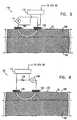
- Fig. 6is a schematic illustration of another electrode assembly 130, comprising a voltage source 136 coupled in series through an optional resistive element 134 to two electrodes, 120 on the surface of skin 22, in accordance with a preferred embodiment of the present invention.
- Optional voltage sensing unit 112measures the voltage drop across resistive element 134 in order to determine the current passing therethrough.
- unit 112 and/or CPU 80 and/or other circuitry in switching unit 50regulate the output of voltage source 136 responsive to the measurement made by unit 112.
- the voltage drop across element 134exceeds a predetermined threshold value, this is used as an indication of stratum corneum ablation and causes the voltage generated by source 136 to be reduced or terminated responsive thereto.
- optional resistive element 134 and optional voltage sensing unit 112are not used, it is preferable to employ other means for significantly reducing the current flow through electrodes 120 after micro-channel formation. This is preferably done by using "self-quenching" printed electrodes, as described hereinabove with reference to Fig. 4 .
- a conductivity-enhancing substance 132is applied to skin 22 prior to placement of electrodes 120 thereon.
- Substance 132typically improves current flow into skin 22 by decreasing the electrical resistance at the interface between electrodes 120 and skin 22.
- Experimental resultsindicate that use of substance 132 has the additional desired effect of increasing the above-mentioned ratio of the lateral component of the electric field to the perpendicular component thereof. In particular, it is believed that substance 132 diffuses into stratum corneum 100 and reduces the lateral resistance and lateral breakdown strength of the stratum corneum.
- Substance 132typically comprises a conductive cream, gel and/or ink.
- substance 132additionally comprises a material which has a high diffusion coefficient into the skin and promotes the increased lateral component of the electric field relative to the perpendicular component, as described hereinabove.
- "pre"-iontophoresisusing a relatively weak electric field, is used to enhance the flow of substance 132 into the outer layer of the skin before application of the stronger electric fields which create the micro-channels. The presence of the conductive substance in the skin subsequent to the pre-iontophoresis is believed to increase the rate of micro-channel creation.
- Pre-iontophoresisis typically implemented by applying, for example, a 3 volt DC field between the electrodes for 30 seconds in order to drive substance 132 into the skin.
- a larger AC current which produces micro-channelsis supplemented by a simultaneous small DC current which supports iontophoresis of substance 132 and thereby enhances micro-channel creation.
- the active substanceis preferably incorporated in substance 132.
- Fig. 7is a schematic illustration of another electrode assembly 150, comprising an AC current source 154 coupled in series with an optional resistive element 152 in order to drive current through electrodes 120 and skin 22, in accordance with a preferred embodiment of the present invention.
- the driving frequency of current through skinhas a significant effect on the sensation or pain experienced by a subject. See, for example, Principles of Applied Biomedical Instrumemation, by L. Geddes and L. Baker, John Wiley & Sons , 198.
- a 10 kHz driving frequencyhas been found to yield good results, although any frequency between about 100 Hz and about 10 MHz is appropriate for most applications.
- the driving frequencyis cyclically modulated between two endpoints (e.g., 2 kHz and 15 kHz) during application of the electric field, such that a graph representing frequency versus time (not shown) is typically sinusoidal or triangular in character.
- Stratum corneum 100generally displays properties of a simple insulator when exposed to DC current, but displays significant capacitance under AC stimulation, particularly when the driving frequency is above 1 kHz. At these frequencies, current flow through the stratum corneum dissipates energy therein, contributing to the heating and ultimate ablation of the stratum corneum.
- the pre-ablation capacitanceproduces a measurable phase shift between the voltage across the electrodes and the current flowing therebetween, which phase shift is seen to be significantly reduced upon commencement and completion of the ablation of the stratum corneum.
- Sensing unit 112is typically used to detect this phase shift by measuring the inter-electrode voltage, as described hereinabove, and by determining the current flow through electrodes 120, preferably by measuring the voltage drop across optional resistive element 152.
- the change of the phase shift from baselineis preferably used by sensing unit 112 and/or CPU 80 and/or other circuitry in switching unit 50 to indicate breakdown of the stratum corneum, responsive to which current flow to electrodes 120 demonstrating such a change preferably is reduced or terminated.
- substance 132is applied to skin 22, and a DC current is superimposed on the AC current in order to cause iontophoresis of substance 132 during micro-channel creation.
- the duration of charge deliveryis limited by means of an optional ordinary timer circuit (not shown).
- the total charge deliveredis limited using methods known in the art.
- energy storage componentssuch as capacitors and/or inductors can be used to modulate charge delivery.
- passing a threshold of current or voltageis used as an indicator of when to reduce the current applied to the skin
- other functions of the current and/or voltagesuch as derivatives, time-integrals, and/or powers thereof may also be evaluated in order to determine when the current should be reduced.
- Fig. 8Ais a schematic illustration of a charge-limited electrode assembly 170, comprising an electrolyte cell 180 connected in series between a power source 172 and electrodes 120, in accordance with a preferred embodiment of the present invention.
- Electrolyte cell 180comprises an anode 174 and a cathode 176, both immersed in an electrolyte solution 178, which acts as a medium for current flow from anode 174 to cathode 176.
- cathode 176is steadily consumed by electrolysis until electrolyte cell 180 becomes substantially non-conductive. In this manner, consumption of cathode 176 progresses at a rate which is generally proportional to the current flowing therethrough.
- cell 180can be built to allow a flow of charge that substantially does not exceed a predetermined value.
- Fig. 8Bis a schematic illustration of another charge-limited electrode assembly 190, comprising a power source 192 which sends current to a large-area anode 194 from which it flows through an electrolyte solution 196 to multiple cathodes 202, in accordance with a preferred embodiment of the present invention.
- the charge-limiting functions embodied in assembly 190are similar to those described with respect to the embodiment shown in Fig. 8A .
- Anode 194comprises a fibrous material, such as paper, having fibers aligned in a generally vertical direction, perpendicular to the surface of skin 22.
- anode 194is in very close proximity to cathodes 202, typically from about 0.1 mm to about 2 mm, in order to enhance independent termination of current through electrodes 198 coupled to cathodes 202, by reducing lateral conduction within the electrolyte solution.
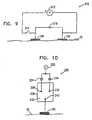
- Fig. 9is a schematic illustration of yet another charge-limited electrode assembly 210, comprising a power source 212 in series with a controlled switch 214, in accordance with a preferred embodiment of the present invention.
- Source 212 and switch 214are connected in series with a capacitor 216 across electrodes 120, which are applied to skin 22.
- CVthe capacitance of the capacitor.
- a typical operational sequence in this preferred embodimentcomprises: (a) turning on source 212; (b) closing switch 214, which results in substantially all of the current from source 212 going through and charging low-impedance capacitor 216; (c) opening switch 214 and turning off source 212; (d) allowing the discharge from capacitor 216 to drive the ablation of the stratum corneum; and (e) passively terminating the process responsive to complete discharge of capacitor 216.
- Fig. 10is a schematic illustration of still another charge-limited electrode assembly 220, comprising an AC source 222 coupled in series to an electrolyte cell 230, electrode 120, and skin 22, in accordance with a preferred embodiment of the present invention.
- Cell 230preferably comprises two alternating nodes 226 and 236 and a common node 240, all nodes being immersed in an electrolyte solution 232. Except as will be described below, the function of electrolyte cell 230 is substantially similar to that of electrolytic charge-limiting devices described hereinabove with reference to Figs. 8A and 8B .
- AC source 222produces a voltage difference across electrodes 120 (only one electrode is shown), which cycles between positive and negative phases at a pre-determined frequency, in order to provide the energy to ablate stratum corneum 100 in skin 22.
- a diode 224 in electrolyte cell 230passes current to cause alternating node 226 to act as an anode and common node 240 to act as a cathode, which is subsequently consumed by the electrolysis thereof during each positive phase.
- diode 224blocks conduction through alternating node 226, halting the consumption of common node 240 associated with the positive phase.
- a second diode 234passes current which allows alternating node 236 to act as a cathode (which is consumed) and common node 240 to act as an anode.
- alternating node 236to act as a cathode (which is consumed)
- common node 240to act as an anode.
- the properties of electrolyte cell 230are determined so that the cell becomes non-conductive after passing a quantity of charge which correlates with breakdown of the stratum corneum.
- Figs. 11A and 11Bare, respectively, a schematic side view of a concentric electrode assembly 250 and a schematic top view of a common electrode layer 252 in assembly 250, in accordance with a preferred embodiment of the present invention.
- a substantially non-conductive substrate 260overlies common electrode layer 252.
- Perforations 254 in layer 252allow passage therethrough of electrodes 262, which receive charge through optional resistive members 256 from a charging bus 264 overlying substrate 260.
- Electrodes 262, which preferably comprise a plurality of conductive fibers,are electrically coupled to skin 22, and cause charge to pass into skin 22 and subsequently out of skin 22 through common electrode layer 252, in order to ablate stratum corneum 100.
- one or more pores 266 traversing substrate 260allow flow of active substances/analytes through substrate 260 from/to a reservoir (not shown) above substrate 260. It is noted that fabrication of concentric electrode assembly 250 is substantially similar to the process of flexible printed circuit production, which is well known in the art.
Landscapes
- Health & Medical Sciences (AREA)
- Life Sciences & Earth Sciences (AREA)
- Public Health (AREA)
- Veterinary Medicine (AREA)
- Radiology & Medical Imaging (AREA)
- Biomedical Technology (AREA)
- Animal Behavior & Ethology (AREA)
- General Health & Medical Sciences (AREA)
- Engineering & Computer Science (AREA)
- Nuclear Medicine, Radiotherapy & Molecular Imaging (AREA)
- Biophysics (AREA)
- Electrotherapy Devices (AREA)
- Surgical Instruments (AREA)
- Measurement Of The Respiration, Hearing Ability, Form, And Blood Characteristics Of Living Organisms (AREA)
- Measuring And Recording Apparatus For Diagnosis (AREA)
- Media Introduction/Drainage Providing Device (AREA)
Description
- The present invention relates generally to devices for drug delivery and analyte extraction, and specifically to devices for puncturing the outer layer of living skin and to devices for transdermal drug delivery any analyte extraction.
- A number of different methods have been developed to perform transdermal drug delivery and/or analyte extraction, including passive diffusion of a drug or analyte between a Skin patch and skin, as well as active processes such as iontophoresis, sonophoresis, electroporation, and chemically enhanced diffusion. These methods are primarily used for generating transdermal movement of small molecules, but generally do not enhance the motion of large molecules through the 10-50 micron thick outermost layer of the skin, the stratum corneum epidermidis.
- In an article, "Micromachined needles for the transdermal delivery of drugs," IEEE 11th Annual International Workshop on Micro-Electro-Mechanical Systems (1998), pp. 494-498, Henry et al. discuss a method of mechanically puncturing the skin with microneedles in order to increase the permeability of skin to a test drug. In the article, microfabrication techniques are described to etch an array of needles in silicon, and experiments performed on cadaver skin with the needle array demonstrated an increase in permeability subsequent to puncture of the skin. The needles are created with a predetermined length, and penetrate to the same depth from the skin surface, regardless of the local thickness of the stratum corneum. It is known that if the needles are longer than the local thickness, then the underlying epidermal tissue may be injured, while if the needles are too short, channel formation through the stratum corneum may be incomplete.
U.S. Patents 4,775,361 ,5,165,418 , and5,423,803 , andPCT Publication WO 97/07734 PCT Publication WO 97/07734 - Electroporation is also well known in the art as a method to increase pore size by application of an electric field. This process is described in an article byChizmadzhev et al., entitled "Electrical properties of skin at moderate voltages," Biophysics Journal, February, 1998, 74(2), pp. 843-856. Electroporation is disclosed as a means for transiently decreasing the electrical resistance of the stratum corneum and increasing the transdermal flux of small molecules by applying an electric field to increase the size of existing pores. Electroporation generally does not produce pores of sufficient diameter to pass large molecules therethrough. Additionally, optimal voltage profiles are difficult to determine because of naturally occurring variations as described hereinabove, as well as the lack of an accurate feedback mechanism to indicate achievement of the desired pore enlargement. If excessive voltage is applied, an irreversible breakdown occurs, resulting in damage to the skin and possible sensations of pain.
U.S. Patent 5,019,034 to Weaver et al. , describes apparatus for applying high voltage, short duration electrical pulses on the skin to produce electroporation, and states that "...reversible electrical breakdown ... along with an enhanced tissue permeability, is the characteristic effect of electroporation."- It is an object of some aspects of the present invention to provide improved apparatus for transdermal delivery of an active substance.
- It is a further object of some aspects of the present invention to provide improved apparatus for transdermal analyte extraction.
- It is yet a further object of some aspects of the present invention to provide improved apparatus for creating narrow channels through the stratum corneum of living skin by puncturing.
- It is still a further object of some aspects of the present invention to provide improved apparatus for reducing sensation and minimizing damage to skin underlying the stratum corneum during channel creation.
- It is an additional object of some aspects of the present invention to provide improved apparatus for controlling the timing of channel creation.
- It is yet an additional object of some aspects of the present invention to provide improved apparatus for regulating channel creation responsive to properties of the skin.
- It is another object of some aspects of the present invention to provide improved apparatus for puncturing the skin and/or transdermally delivering an active substance and/or transdermally extracting an analyte, using a miniature, self-contained device.
- It is yet another object of some aspects of the present invention to provide improved apparatus for transdermally delivering an active substance using a standard medical skin patch.
- Disclosed is a device for enhancing transdermal movement of a substance comprising: (a) a skin patch, with at least two electrodes in contact with the skin of a subject; and (b) a control unit, coupled to the patch, which causes a current to pass between the electrodes through the stratum corneum epidermidis, in order to generate at least one micro-channel in the stratum corneum to enable or augment transdermal movement of the substance. Preferably, the control unit comprises switching circuitry to control the magnitude and/or duration of the electric field at the electrode.
- The term "micro-channel" as used in the context of the present patent application and in the claims refers to a pathway generally extending from the surface of the skin through all or a significant part of the stratum corneum, through which pathway molecules can diffuse. Preferably, micro-channels allow the diffusion therethrough of large molecules at a greater rate than the same molecules would diffuse through pores generated by electroporation. It is believed that such micro-channels are formed due to local power dissipation leading to ablation of the stratum corneum when an electric field of sufficient magnitude is applied to a small area of the skin, in contact with the electrodes, for a certain period of time. Unlike methods of electrically-promoted drug delivery known in the art, such as iontophoresis and electroporation, the present invention enables relatively large channels to be formed, through which even large molecules of the active substance can pass rapidly, without the necessity of ionizing or polarizing the molecules.
- The current flow between the electrodes can be described as having two componens:
- (a) a perpendicular component, which is generally perpendicular to the skin surface {and, if the associated electric field is sufficiently large, may cause current to go through the stratum corneum into the underlying epidermal tissue and dermis); and (b) a lateral component, generally parallel to the skin surface, which remains generally within the stratum corneum. Substantially all of the current generated at one electrode ultimately emerges from the skin and is taken up by an adjacent electrode.
- In preferred embodiments of the present invention, apparatuses are employed to increase the relative value of the lateral component with respect to the perpendicular component. In general, the stratum corneum epidermidis (the-superficial layer of the epidermis) demonstrates a significantly higher resistance to the passage of molecules therethrough than does the underlying epidermal tissue. It is therefore an object of these preferred embodiments of the present invention to form micro-channels in the stratum corneum by ablating the stratum corneum in order to increase conductance of the substance therethrough, and to generally not directly affect or damage epidermal tissue underlying the stratum corneum or in the innervated dermis. Additionally, limiting current flow substantially to the non-innervated stratum corneum is expected to decrease or eliminate the subject's sensations, discomfort, or pain responsive to use of the present invention, particularly as compared with other procedures known in the art.
- A voltage applied between two electrodes on the skin generates an electric field that is to a large extent confined to the volume in a vicinity of the electrodes. Thus, electrodes which are widely spaced produce a field -- and current flow responsive thereto - which extends relatively deep into the skin. Conversely, electrodes which are closely spaced do not generate significant current flow at deeper layers. Therefore, in some preferred embodiments of the present invention, the electrodes of the device are separated by distances smaller than about 100 microns (but for some applications by distances of up to approximately 500 microns), in order to generate a current flow which is largely confined to a thin layer, comprising most or all of the stratum corneum. This effectively results in a desired larger value of the ratio of the lateral component to the perpendicular component, as described hereinabove.
- In some exemplary arrangements, a high-frequency AC current with an optional DC current added thereto is applied between the closely-spaced electrodes in order to generate lateral capacitive currents in the stratum corneum and to cause breakdown and micro-channel formation in the stratum corneum.
- In some exemplary arrangements the patch comprises an array of electrodes, preferably closely-spaced electrodes, which act together to produce a high micro-channel density in an area of the skin under the patch. Preferably, the control unit and/or associated circuitry sequentially or simultaneously evaluates the current flow through each electrode, or a subset of the electrodes, in order to determine when one or more micro-channels have formed responsive to the applied field. Responsive thereto, the control unit discontinues application of the field. Since the formation of a micro-channel is typically marked by a local drop in electrical resistance of the skin, the control unit may, for example, reduce the voltage or current applied at any electrode wherein the current has exceeded a threshold. By reducing -current flow upon or shortly after micro-channel formation, the likelihood of skin burns or pain sensations is minimized.
- In some, exemplary arrangements, a relatively high voltage is applied to the electrodes initially, so as to induce formation of micro-channels through the skin. A property of the current flow is detected, and the current is reduced or terminated when the property reaches a predetermined threshold. Preferably, the detected property of the current flow is secondary to changes in a conduction property of the skin, responsive to formation of one or more micro-channels through the stratum corneum.
- Alternatively or additionally, a time-varying voltage V(t), characterized, for example, by the formula V(t) = V0 + k*(t^n), is applied between a first electrode and a second electrode in the skin patch until a shut-off signal is generated. (Constants k and n are nonnegative.) Other forms of V(t) may include a sinusoid, an exponential term, or a series of pulses. A current I(t), flowing responsive to the applied field, is measured by the control unit, as described hereinabove. Calculations of the values of Integral[I(t)dt], dI/dt and/or d2I/dt2 are frequently performed. Comparisons of I and/or Integral[I(t)dt] and/or dI/dt and/or d2I/dt2 with respective threshold values are used as indicators of micro-channel formation and/or to determine when to generate the shut-off signal for the electrodes.
- Further alternatively or additionally, in exemplary arrangements in which V(t) is sinusoidal, the control unit preferably calculates changes in a phase shift between V(t) and I(t) during application of the electric field, and controls the field responsive to these changes. It is believed that cells in the stratum corneum demonstrate capacitance, which causes the phase shift, and that ablation of the stratum corneum decreases the capacitance and is evidenced by a decrease in the phase shift.
- Still further alternatively or additionally, the total charge which is passed through the skin is limited by a capacitor, inductor, or other energy-storage device. An appropriate choice of values for these components sets an absolute maximum quantity of charge which can pass through the skin, and thus limits any damage that can be caused thereby.
- In some preferred embodiments of the present invention, one or more of the electrodes comprise or are coupled to an electrically conductive dissolving element, where the dissolving rate is generally proportional to the current passing through the electrode. When a sufficient quantity of charge has passed through the dissolving element, the electrode ceases to conduct electricity. Thus, a maximum total charge, Qtotal, is associated with an electrode, such that current flows through the element for only as long as q(t), defined as Integral[I(t)dt], is less than Qtotal. This serves as a safety feature, reducing the possibility of skin burns secondary to applied electric fields. Alternatively or additionally, the dissolving element is constructed so that it becomes non-conductive after a quantity of charge has passed therethrough which is sufficient to ablate the stratum corneum.
- In some further preferred embodiments of the present invention, the electrodes are "printed" directly on the skin, preferably by stamping or by employing a transfer patch of a conductive substance (such as, for example, a conductive ink containing silver grains). In applications of such embodiments of the present invention for transdermal drug delivery, the conductive substance preferably comprises a matrix holding the drug to be administered to a subject.
- Preferably, the printed electrodes demonstrate a substantially complete loss of conductance therethrough upon ablation of the stratum corneum responsive to the applied electric field. Further preferably, each printed electrode comprises a material which is conductive only when current flowing therethrough remains below a threshold value. If the current exceeds the threshold, then thermal fusion of the material causes it to become largely nonconductive, i.e. the material acts as a fuse. Still further preferably, current continues to flow through the other electrodes until they reach the threshold current, at a time which is generally associated with the time required for ablation of the stratum corneum, as described hereinabove. In some of these embodiments, the control unit may be made substantially simpler than as described regarding other embodiments, and generally does not need other circuitry in order to determine whether to generate a shut-off signal.
- In still further preferred embodiments of the present invention, two electrodes on the patch form a concentric electrode pair, in which an inner electrode generates a current which passes through the stratum corneum to an outer electrode surrounding the inner electrode. The distance between the inner and outer electrodes is preferably between about 50 and about 200 microns, in order to maintain the ratio of the lateral to the perpendicular component of the current at a high value, as described hereinabove.
- In some exemplary arrangements, a conductance-enhancing substance, preferably comprising a conductive cream or ink, is applied to the skin in order to increase the ratio of the lateral to the perpendicular component of current flow. Alternatively or additionally, the conductance-enhancing substance comprises a composition with a high diffusion coefficient, which diffuses into the lipid layers of the stratum corneum and further augments the selective power dissipation-therein, in order to ablate the stratum corneum with substantially little damage to the underlying tissue. In some applications, the substance has an electrical charge associated therewith, such that when a small lateral field is applied, lateral diffusion of the substance within the stratum corneum is enhanced (i.e., iontophoresis of the substance).
- In some exemplary arrangements, which utilize a conductance-enhancing substance, the substance further comprises an active substance, for example, a pharmaceutical product, dissolved or mixed therein. Since breakdown of the stratum corneum is often associated with removal of the enhanced conductivity path afforded by the conductance-enhancing substance, it is preferable in many of these exemplary arrangements to use a substantially constant voltage source to generate current at the electrodes. Removal of the enhanced conductivity path will result in a desired reduced power dissipation in the stratum corneum (P = V2/R), since the voltage remains constant while resistance increases.
- In other preferred embodiments of the present invention, ablation of the stratum corneum is accomplished using a current-limited source to power the electrodes. It is believed that the stratum corneum generally displays high electrical resistance, while epidermal tissue underlying the stratum corneum has significantly lower electrical resistance. Ablation of the stratum corneum (i.e., removal of the high-resistance tissue) is therefore associated with a net decrease of electrical resistance between the electrodes, and the power dissipated in the epidermis following electrical breakdown will decrease, typically proportional to the change in resistance (P = I2R).
- Monitoring changes in voltage, current, and/or phase for each electrode in the control unit may require, in certain implementations, a significant amount of circuitry. Therefore, in some, exemplary arrangements, the control unit comprises one or more clusters of electrodes, in which monitoring and control are performed for each cluster rather than for the individual electrodes therein. The cluster is preferably over a relatively small area of skin, for example, from about 1 mm2 to about 100 mm2, in which properties of the skin are assumed to be substantially constant.
- In some preferred embodiments of the present invention, the device is a stand-alone device, which enables transdermal delivery of an active substance or enhances transdermal motion of an analyte. Alternatively, the device creates micro-channels as described hereinabove and is then removed from the skin, in order to enhance the transdermal delivery of a substance into or out of a commercially-available skin patch subsequently placed on the skin. In other preferred embodiments of the present invention, the device is an add-on to commercially available transdermal drug delivery/analyte extraction devices, and serves primarily to create the micro-channels in the stratum corneum, and optionally to act as a vehicle through which the substance may pass.
US-A-5681282 discloses an electrosurgical probe comprising an electrode array disposed over a recessed surface near a distal end of a shaft. The array includes a plurality of electrically isolated electrode terminals having substantially the same potential. A connector is disposed at a proximal end of the shaft for electrically coupling the electrode terminals to a high frequency voltage source.WO-A-97/16222 - The invention provides a device in accordance with claim 1 bellow.
- A device for thermally ablating stratum corneum epidermidis of skin on the body of a subject, comprising:
- a plurality of electrodes, which are adapted to be applied to the skin of the subject at respective points;
- a power source, which is adapted to apply electrical energy by being adapted to generate alternating current at a frequency that is between 1 kHz and 300 kHz, between two or more of the plurality of electrodes, to cause thermal ablation of the stratum corneum primarily in an area intermediate the respective points; and a medical patch that contains a substance and that has an adhesive-coated undersurface, the medical patch being couplable to the electrodes,
- wherein the device is adapted to thermally ablate the area of the stratum corneum in order to allow the substance to pass therethrough.
- Preferably, skin layers beneath the stratum corneum are substantially not ablated. In a preferred embodiment of the present invention, the ablation of the stratum corneum causes a puncturing thereof.
- Further preferably, the substance includes a drug that is delivered through the skin. Alternatively, the substance includes an analyte that is extracted through the skin.
- Preferably, the power source generates an electric field which causes a current to flow through the stratum corneum, and the device reduces power dissipated in the stratum corneum responsive to variation of a characteristic of the current. Further preferably, the characteristic is drawn from a list consisting of: the magnitude of the current; a time-integration of the current; a first time-derivative of the current; and a second time-derivative of the current
- Alternatively or additionally, current through one of the plurality of electrodes is reduced substantially independently of the current through another one of the plurality of electrodes.
- Further alternatively or additionally, at least one of the plurality of electrodes is coupled to receive the current through a limited-conduction unit, which unit allows current below a threshold value to flow therethrough substantially unimpeded, and becomes substantially non-conductive if the current flowing therethrough exceeds a limited-conduction threshold value.
- Preferably, at least one of the plurality of electrodes is coupled to an electrically-conductive dissolving element characterized by a dissolving rate generally proportional to the current passing therethrough, which becomes substantially nonconductive responsive to a function of the current. In a preferred embodiment, the function includes a time integral of the current having passed through the dissolving element.
- Preferably, the dissolving element includes:
- an electrolyte solution within the element; and
- a first node and a common node immersed in the electrolyte solution,
- wherein current flows from the first node to the common node through the electrolyte solution, the current flow causing the common node to be consumed at a rate generally proportional to the current passing therethrough, such that the dissolving element becomes substantially nonconductive when the total charge having passed through the common node exceeds a common node threshold value.
- Further preferably, the dissolving element also includes a second node, immersed in the electrolyte solution, wherein the power source generates alternating current, and wherein the device further includes:
- a first diode, coupled in series between the power source and the first node, which conducts current from the power source to the first node when the alternating current is in a positive phase thereof; and
- a second diode, coupled in series between the power source and the second node, which conducts current from the second node to the power source when the alternating current is in a negative phase thereof.
- such that the dissolving element becomes substantially nonconductive when the total charge having passed through the common node exceeds a common node threshold value.
- Alternatively, the dissolving element includes:
- an electrolyte solution within the element;
- a large-area anode immersed in the electrolyte solution; and
- a plurality of cathodes, immersed in the electrolyte solution, each of the cathodes being coupled to a respective one of the plurality of electrodes,
- wherein current flows from the large-area anode to the plurality of cathodes through the electrolyte solution, the current flow causing at least one of the cathodes to be consumed at a rate generally proportional to the current passing therethrough, and wherein the at least one cathode becomes substantially nonconductive responsive to a function of the current having passed therethrough.
- Preferably, the current through at least one of the plurality of electrodes is reduced responsive to the variation of the characteristic of the current through another one of the plurality of electrodes.
- In a preferred embodiment, the device also includes a voltage sensing unit coupled to measure a voltage drop across two of the plurality of electrodes, and current from the power source is reduced responsive to the measurement made by the sensing unit. Preferably, the power source includes a current source, and current from the current source is reduced responsive to a measurement made by the sensing unit which indicates that the electrical potential between the two electrodes is below a voltage-threshold value.
- Alternatively or additionally, the device includes a resistive element coupled to one of the two electrodes and to the power source, and the voltage sensing unit is further coupled to measure a voltage drop across the resistive element in order to determine a current passing therethrough. The power source includes an alternating current source, such that the measurements of the voltage drop across the two electrodes and the current through the resistive element determine a phase shift. The current from the alternating current source is reduced responsive to the phase shift being below a threshold value.
- In a preferred embodiment, the device includes:
- a resistive element coupled to one of the plurality of electrodes and to the power source; and
- a voltage sensing unit coupled to measure a voltage drop across the resistive element in order to determine a current passing therethrough.
- In this preferred embodiment, the power source includes a voltage source, and the voltage is reduced responsive to a measurement made by the sensing unit which indicates that the current through the resistive element is above a current-threshold value.
- In another preferred embodiment, at least one of the plurality of electrodes is printed directly on the skin and becomes substantially electrically nonconductive responsive to the value of the current passing therethrough being greater than a threshold value.
- In yet another preferred embodiment, the device includes:
- a capacitor, coupled to two of the plurality of electrodes; and
- a switch, coupled to the power source and the capacitor, such that the switch, in a closed phase thereof, allows current to flow from the power source to the capacitor and to the two electrodes, and such that the switch, in an open phase thereof, substantially terminates current flow from the power source to the capacitor and to the two electrodes.
- In this embodiment, the power source charges the capacitor during the closed phase, and the capacitor discharges current through the electrodes during the open phase.
- Preferably, the distance between two of the plurality of electrodes is less than about 0.3 mm. Further preferably, the distance between two of the plurality of electrodes is between about 0.01 mm and about 0.1 mm.
- Preferably, the plurality of electrodes include:
- a common electrode, which has a plurality of perforations therethrough; and
- a plurality of positive electrodes, each positive electrode passing through a respective perforation of the common electrode,
- such that current from the power source flows from each positive electrode through the skin to the common electrode.
- In a preferred embodiment, the power source generates alternating current, a frequency thereof being above about 100 Hz. Preferably, the frequency is between about 1 kHz and about 300 kHz. Alternatively or additionally, the power source modulates a frequency of the alternating current between a first frequency value and a second frequency value.
- There is further provided, in accordance with a preferred embodiment of the present invention, a device for passing electrical current through the skin of a subject, including:
- a power source, which generates the current;
- a plurality of electrodes, which are applied to the skin at respective points; and
- an electrically conductive dissolving element coupled to at least one of the electrodes, the element being characterized by a dissolving rate generally proportional to the current passing therethrough, and becoming substantially nonconductive responsive to a function of the current passing therethrough.
- There is also provided, in accordance with, an exemplary arrangement, a method for ablating the stratum corneum epidermidis of a subject, including:
- placing a plurality of electrodes against the subject's skin at respective points; and
- applying electrical energy between two or more of the plurality of electrodes, in order to cause ablation of the stratum corneum primarily in an area intermediate the respective points.
- Skin layers beneath the stratum corneum are substantially not ablated. In an exemplary arrangement applying the electrical energy includes puncturing the skin.
- Applying the energy includes ablating the area of the stratum corneum in order to allow a substance to pass through the area. Further, the method includes delivering a drug or extracting an analyte through the area.
- Applying electrical energy includes:
- causing a current to flow through the points on the skin; and
- substantially reducing the current flow through the skin responsive to variation of a characteristic of the current.
- In an exemplary arrangement, the characteristic is drawn from a list consisting of: a magnitude of the current; a time-integration of the current; a first time-derivative of the current; and a second time-derivative of the current.
- In another exemplary arrangement, causing the current to flow includes passing current to the one or more points on the skin through one or more respective limited-conduction units, wherein the units allow current below a threshold value to flow therethrough substantially unimpeded. and wherein the units become substantially nonconductive if the current flowing therethrough exceeds a limited-conduction threshold value.
- In another exemplary arrangement causing the current to flow includes passing current to the one or more points on the skin through one or more respective electrically conductive dissolving elements, each element characterized by a dissolving rate generally proportional to the current passing therethrough, and each element becoming substantially nonconductive when the total charge having passed therethrough exceeds a dissolving element threshold value.
- In yet another exemplary arrangement, reducing the current flow includes reducing the current at one of the respective points substantially independently of the current at another one of the respective points.
- In still another exemplary arrangement, reducing current flow includes:
- monitoring the current flow through one of the plurality of electrodes; and
- reducing the current flow through another one of the plurality of electrodes responsive thereto.
- Preferably, placing the plurality of electrodes includes placing two of the plurality of electrodes at a separation therebetween that is less than about 0.3 mm. Further preferably, placing the plurality of electrodes includes placing the two of the plurality of electrodes at a separation between about 0.01 mm and about 0.1 mm.
- In an exemplary arrangement, placing the plurality of electrodes includes:
- applying a conduction-enhancing material to an area on the surface of the subject's skin in order to enhance current flow through the skin; and
- placing the electrodes on the material,
- wherein the electrical resistance of the conduction-enhancing material increases responsive to a function of the current flow therethrough.
- Placing the plurality of electrodes includes:
- placing on the skin a common electrode which has a plurality of perforations therethrough; and
- placing on the skin a plurality of positive electrodes, each positive electrode passing through a respective perforation in the common electrode,
- such that current from the power source flows from each positive electrode through the skin to the common electrode.
- Further, the method includes positioning in a vicinity of the electrodes a medical patch containing the substance, such that ablation of the stratum corneum increases a transport rate of the substance from the patch into the skin.
- In an exemplary arrangement, applying electrical energy includes generating alternating current, a frequency thereof being above about 100 Hz. The frequency is between about 1 kHz and about 300 kHz. Alternatively or additionally, applying electrical energy includes modulating a frequency of the alternating current between a first frequency value and a second frequency value.
- There is additionally provided, in accordance with an exemplary arrangement, a method for passing electrical current through the skin of a subject, including:
- placing a plurality of electrodes against the skin at respective points;
- applying the current through the electrodes; and
- coupling to at least one of the electrodes an electrically conductive dissolving element, the element being characterized by having a dissolving rate generally proportional to the current passing therethrough, and by becoming substantially nonconductive responsive to a function of the current passing therethrough.
- The present invention will be more fully understood from the following detailed description of the preferred embodiments thereof, taken together with the drawings in which:
Fig. 1A is a schematic, partly sectional illustration of a device for transdermal transport of a substance, in accordance with a preferred embodiment of the present invention;Fig. 1B is a schematic, partly sectional illustration of another device for transdermal transport of a substance, in accordance with a preferred embodiment of the present invention;Fig. 2 is a schematic bottom view of the device ofFig. 1A , in accordance with a preferred embodiment of the present invention;Fig. 3 is a schematic illustration of a switching unit in the device ofFig. 1A , in accordance with a preferred embodiment of the present invention;Fig. 4 is a schematic illustration of an electrode assembly, in accordance with a preferred embodiment of the present invention;Fig. 5 is a schematic illustration of another electrode assembly, in accordance with a preferred embodiment of the present invention;Fig. 6 is a schematic illustration of yet another electrode assembly, in accordance with a preferred embodiment of the present invention;Fig. 7 is a schematic illustration of still another electrode assembly, in accordance with a preferred embodiment of the present invention;Figs. 8A and 8B are schematic illustrations of charge-limited electrode assemblies, in accordance with preferred embodiments of the present invention;Fig. 9 is a schematic illustration of another charge-limited electrode assembly, in accordance with a preferred embodiment of the present invention;Fig. 10 is a schematic illustration of yet another charge-limited electrode assembly, in accordance with a preferred embodiment of the present invention;Fig. 11A is a schematic side view of a concentric electrode assembly, in accordance with a preferred embodiment of the present invention; andFig. 11B is a schematic top view of a common electrode layer in the concentric electrode assembly ofFig. 11A , in accordance with a preferred embodiment of the present invention.Fig. 1A is a schematic, partly sectional illustration of askin puncturing device 20 for transdermal delivery of an active substance and/or transdermal extraction of an analyte, in accordance with a preferred embodiment of the present invention.Device 20 comprises acontrol unit 30 attached to askin patch 40, which is preferably fixed to a suitable area of a subject'sskin 22.Device 20 preferably administers an active substance through the normally substantially-impermeable stratum corneum layer of the skin by passing a controlled electric current therethrough, thereby ablating the stratum corneum and generating micro-channels through which the substance can pass. Alternatively or additionally,device 20 is used to generate micro-channels in the stratum corneum in order to allow passage of molecules to patch 40 from the underlying tissue, generally for diagnostic purposes.- When
device 20 drives current through the stratum corneum, this tissue is heated resistively, so that when a sufficient quantity of energy has passed therethrough in a short time period, the tissue is ablated by the total energy dissipated therein. This ablation creates the desired micro-channels. i.e. physical gaps in the tissue. It has been found that application of a current to a small area of the skin leads to formation of such micro-channels, through which even large molecules can pass relatively freely, without the necessity of ionizing or polarizing the molecules, and without causing pain or substantial trauma to the dermis and epidermal tissue underlying the stratum corneum. Control unit 30 preferably comprises aswitching unit 50, a battery 52 (such as a lithium coin cell battery), and an optional user-interface comprising buttons 54 and asensible signal generator 56, which may comprise a display and/or a buzzer. In a simplest embodiment,buttons 54 initialize and terminate analyte extraction or delivery of the active substance, althoughbuttons 54 preferably also programmably control extraction or dosage rate and duration.Patch 40 comprises two ormore electrodes 60, preferably anarray 75 of electrodes, which pass current into and out of the skin. In applications ofdevice 20 for transdermal drug delivery, when a micro-channel has formed responsive to current flow between the electrodes, the active substance stored inpatch 40 flows therethrough. In the patch, the active substance is preferably stored in or applied tointer-electrode regions 68 and flows directly therefrom into the micro-channels created in the skin.Control unit 30, containing switchingunit 50 andbattery 52, is preferably designed for repeated use, to be removably attached todisposable skin patch 40. Before use,control unit 30 is fitted ontopatch 40, and a protective tab (not shown) on the lower surface ofpatch 40 is preferably removed, exposing the one ormore electrodes 60, and, in drug delivery systems, the active substance. One or more optional alignment pins 32 are incorporated intocontrol unit 30 and/orskin patch 40 to maintain proper alignment therebetween. Fittingcontrol unit 30 to patch 40 also coupleselectrical contacts 62 on a lower surface ofcontrol unit 30 withelectrical contacts 58 on an upper surface ofskin patch 40. In some other exemplary arrangements (not shown),control unit 30 andskin patch 40 are constructed as one integrated unit.Fig. 1B is a schematic, partly sectional illustration of anotherdevice 21 for transdermal transport, of a substance, in accordance with a preferred embodiment of the present invention.Device 21 operates in substantially the same manner asdevice 20, described hereinabove, butdevice 21 is used in an add-on configuration with commercially available medical patches. Typically, amedical patch 74 is coupled to a porous, thin, flexible, anddisposable electrode patch 70, which is used to create micro-channels inskin 22 so as to enable enhanced flow of an active substance stored withinmedical patch 74 throughelectrode patch 70 and intoskin 22.Electrode patch 70 is constructed such thatelectrical contacts 58 thereof are coupled toelectrical contacts 62 ofcontrol unit 30 and carry charge throughflexible leads electrodes 120 placed against the surface ofskin 22. Prior to use,medical patch 74 is placed ontoelectrode patch 70, typically on the opposite side ofpatch 70 fromelectrodes 120. An adhesive on the underside ofmedical patch 74 secures the two patches together. Subsequently,electrode patch 70 is folded over, as shown inFig. 1B , such that an upper surface ofpatch 74 is secured through an adhesive 72 toelectrode patch 70. During operation ofdevice 21, the active substance diffuses from the lower surface ofpatch 74 into, and then through,patch 70 intoskin 22.Device 21 is thus compatible with a broad range of currently available active or passive medical patches, which are typically of the same general construction (thin shell, internal reservoir of active substance, porous and adhesive-coated undersurface).- It is understood, of course, that
device 21 as described is only one of many ways to implement some aspects of the present invention. Alternatively, for example,electrode patch 70 is not folded over; instead, controlunit 30 is placed next tomedical patch 74 on top ofelectrode patch 70. Further alternatively,control unit 30 has electrical contacts on its upper surface to which are coupled the electrical contacts of the electrical patch. Fig. 2 is a schematic bottom view ofskin patch 40 fromFig. 1A , showingarray 75 ofelectrodes 60, in accordance with a preferred embodiment of the present invention. Althougharray 75 as shown comprises sixteen electrodes, it is understood that in some implementations the array might be smaller, while in others the array might be larger, for example 50 x 50 or even more, so as to enable a greater amount of the active substance to be delivered or analyte to be extracted.Electrodes 60 in this embodiment are preferably organized into eight electrode sets 77, such that most of the charge leaving one electrode in a set goes to the other electrode in that set, and generally does not go to electrodes in an adjacent set. Electrode sets 77 are further preferably densely packed in order to maximize the transdermal transfer rate. By way of illustration and not limitation, the density may range from 4 - 100 electrode sets/cm2. Each electrode set typically generates at least one micro-channel before a threshold of current or total charge transfer is passed, responsive to which switchingunit 50 preferably causes current to the electrode set to be terminated or reduced, es described herein.Fig. 3 is a schematic illustration of switchingunit 50 indevice 20 ofFig. 1A , configured to control a 4x4 array ofelectrodes 60, as inFig. 2 , in accordance with a preferred embodiment of the present invention.Switching unit 50 preferably comprises aCPU 80 which actively controls the voltage V(t) applied to sixteenconductors 90 leading toelectrodes 60.CPU 80 monitors the current flow, I(t), through each ofconductors 90 leading toelectrodes 60 in order to determine whether a characteristic of the current (e.g., time-integrated current, I, dI/dt, d2I/dt2) has surpassed a threshold, indicating micro-channel formation. The CPU terminates current flow to any electrode for which the threshold has been surpassed. Alternatively or additionally, in some applications, some ofelectrodes 60 are generally not used to initiate channel formation, but serve primarily to allowCPU 80 and/or other circuitry to monitor electrical properties ofskin 22.CPU 80, which receives a clock signal from anoscillator 92, preferably communicates with andcontrols electrodes 60 through eight data lines 81 and fourcontrol lines 85 which lead to an A/D-D/A converter 82, and by fiveaddress lines 84 and fourcontrol lines 86 which lead to amultiplexing unit 88. It will be understood by one skilled in the art that there are many methods to monitor and control current through a plurality of conductors, and that using a CPU, A/D-D/A converter and multiplexing unit as described herein is just one of these. Generally, data lines 81 carry in alternation a low byte and a high byte of data between the CPU and A/D-D/A converter 82. Typically, 10 bits of data, representing a desired voltage for one of the sixteen electrodes, are converted to an analog voltage in A/D-D/A converter 82, and this voltage is passed by multiplexingunit 88 to an appropriate electrode, the electrode selection being determined by the binary values represented in address lines 84. In many applications, fewer than 10 bits are required to define voltages for the respective electrodes, and circuitry within switchingunit 50 is accordingly simpler.- Intermittently;
CPU 80 enters a current-sensing mode, wherein switchingunit 50 continues to drive current throughconductors 90, but the CPU changes the state ofcontrol lines conductors 90. Responsive to the change incontrol lines 86, multiplexingunit 88 measures a current through one ofconductors 90, converts this measurement to a voltage, and passes the voltage to A/D-D/A converter 82 which in turn passes the digital value representing the current to the CPU. Preferably,CPU 80 scans through each of the sixteen electrodes, detects a present current flow value, stores this value in anoptional memory unit 89, optionally compares the value with prior values for the same electrode in order to calculate Integral[I(t)dt], dI/dt and/or d2I/dt2, and regulates the potential of that electrode responsive to the current measurement and/or optional calculation. It will be understood by one skilled in the art thatCPU 80,oscillator 92, andmemory 89 could be replaced by other circuitry able to perform generally the same functions. Fig. 4 is a schematic illustration of anelectrode assembly 94, comprising a plurality ofelectrodes 120, which are placed onskin 22 in order to generate micro-channels in thestratum corneum 100, in accordance with a preferred embodiment of the present invention.Electrodes 120 inassembly 94 are grouped in sometimes overlapping sets of two or more electrodes, forming a plurality of electrode sets 124, one of which is indicated with a dashed line inFig. 4 . Current, coming from switchingunit 50, generally flows from one electrode in each electrode set to the other electrodes of the set. An arrow going between the two electrodes inset 124 indicates the preferred flow of current.- Preferably, the spacing between electrodes in each electrode set is smaller than about 0.1 mm, although for some applications it may range from (by way of illustration and not limitation) 0.1 mm to about 0.3 mm. Generally, the distance is set such that an electric field penetration depth is achieved which is substantially of the same magnitude as the thickness of the stratum corneum, so that the current mostly does not enter epidermal tissue underlying the stratum corneum. Experimental results have shown that the depth of deepest ablation is generally similar to the electrode spacing, so maintaining the spacing between about 0.01 mm and about 0.1 mm optimizes generation of micro-channels while substantially reducing damage, sensation and/or pain in the innervated dermis and in the epidermal tissue below the stratum corneum.
- At any point in the skin in a vicinity of two electrodes placed thereon, the electric field generated between the electrodes can be viewed as having fundamentally two components: a component perpendicular to the skin, which generally causes current flow perpendicular to the skin; and a lateral component, which generally causes current flow parallel to the skin. At a point in the skin infinitesimally below one of the electrodes, the perpendicular component is generally large and/or greater than the lateral component. The present invention seeks generally to maximize the ratio of the lateral component to the perpendicular component at the depth corresponding to the interface between the deepest portion of the stratum corneum and the most superficial portion of the remainder of the epidermis. An electric field at the base of the stratum corneum having a relatively large lateral component generates current flow predominantly in the stratum corneum, with relatively little current flow into the underlying epidermal tissue. Thus, using methods and apparatus of the present invention, tissue ablation occurs mostly in the stratum corneum, as desired, and largely does not occur in the underlying tissue.
- In some applications of the embodiment shown in
Fig. 4 , it is preferred to printelectrodes 120 directly onskin 22, typically (a) by stamping the electrodes thereon; (b) by employing a transfer patch of a conductive substance; and/or (c) by other techniques known in the art.Switching unit 50 preferably sends current to the printed electrodes via printed ports (not shown) on the upper surface of the electrodes. In uses of the present invention for transdermal drug delivery, the conductive substance preferably contains an active substance, typically dissolved or suspended therein. Alternatively or additionally, it is desirable for the printed electrode to disconnect from the switching unit or power source at substantially the same time as ablation of the stratum corneum is completed. This "self-quenching" feature of the printed electrodes is typically achieved by controlling fabrication of the electrodes, in particular by regulating the thickness and/or chemical composition thereof. Printed electrodes comprising a silver-based emulsion ink preferably undergo thermal fusion within the ink responsive to high current flow, resulting in a decrease in electrical conduction therethrough. - As discussed hereinabove with reference to
Fig. 3 , switchingunit 50 monitors current flow to electrodes 60 (orelectrodes 120, shown inFig. 1B and subsequent figures), and selectively terminates the flow to one or more electrodes upon a determination that ablation ofstratum corneum 100 has occurred. Making reference toFig. 4 , acluster 96 of electrodes is a grouping ofelectrodes 120, which are typically in very close mutual proximity, and are therefore assumed to overlie an area ofskin 22 which has generally uniform properties. By way of illustration and not limitation, cluster sizes generally range from about 4 mm2 to about 100 mm2.Switching unit 50 preferably monitors and terminates the current flow through the electrodes incluster 96 collectively (i.e. for all of the electrodes, not individually for each electrode). Alternatively or additionally, current throughelectrodes 120 incluster 96 is determined by monitoring the current in only a subset of the electrodes, and assuming the value derived therefrom to be generally representative of current through each of the other electrodes. Upon a determination by switchingunit 50 thatstratum corneum 100 undercluster 96 has been ablated, the current flow to all of the electrodes incluster 96 is substantially terminated. Monitoring of clusters of electrodes generally simplifies control circuitry associated with the invention, while not substantially decreasing the performance thereof. - Optional
resistive elements 98, coupled in series between switchingunit 50 andelectrodes 120, limit the power dissipation in the skin following the large increase of conductivity in the epidermis associated with ablation of the stratum corneum. Typical values forresistive elements 98 range from 1 kOhm - 100 kOhms, but in some applications may have values outside of this range. Fig. 5 is a schematic illustration of anotherelectrode assembly 110, comprising acurrent source 114 coupled to drive charge throughelectrodes 120 onskin 22, in accordance with a preferred embodiment of the present invention.Current source 114 preferably comprises a source of electrical power (for example, a battery) connected in series with an inductive element which, due to pulse charging, exhibits properties of a current source, thereby limiting the power dissipated in underlyingepidermal tissue 102 following the drop in resistance of the epidermis associated with substantially complete ablation ofstratum corneum 100. -Alternatively or-additionally, current-limited source 114 comprises active-components such as transistors, op-amps, commercially-available "ideal" current sources, etc., which maintain the current through the skin generally constant after ablation of the stratum corneum, so that the power dissipated (P = I2R) will decrease with the reduced resistance of the skin upon the electrical breakdown ofstratum corneum 100.- Prior to breakdown, the impedance between
electrodes 120 is high, producing a generally large voltage drop therebetween, so the energy dissipated in the skin (P = VI) has a desired high value. The energy dissipation rate is preferably sufficient to cause electrical breakdown ofstratum corneum 100 in a short time, which is typically less than 50 milliseconds, but may range from about 1 to about 1000 milliseconds. Reported values of the voltage needed to break downstratum corneum 100 spread over a range of approximately 5 - 1000 volts. For the purposes of the present invention, it has been found that an inter-electrode voltage of approximately 100 volts generally ablatesstratum corneum 100 without causing significant damage tounderlying tissue 102. It is understood, however, that for some applications or types of subjects/patients, lower or higher inter-electrode voltages may be more suitable. - Intermittently or continuously during application of the electric field to
skin 22, an optionalvoltage sensing unit 112 preferably measures the interelectrode voltage and sends a signal corresponding thereto toCPU 80 or other circuitry in switchingunit 50, which regulates the current produced bysource 114 responsive to the signal. Alternatively or additionally,voltage sensing unit 112 comprises a comparator which intermittently or continuously compares the interelectrode voltage to a pre-determined threshold value, and signalssource 114 when the voltage is below the threshold. In either case, the CPU, circuitry and/or comparator preferably controlsource 114 to reduce or terminate current flow responsive to a drop of the interelectrode voltage below the threshold value. Fig. 6 is a schematic illustration of anotherelectrode assembly 130, comprising avoltage source 136 coupled in series through an optionalresistive element 134 to two electrodes, 120 on the surface ofskin 22, in accordance with a preferred embodiment of the present invention. Optionalvoltage sensing unit 112 measures the voltage drop acrossresistive element 134 in order to determine the current passing therethrough. In a manner substantially similar to that described hereinabove with reference toFig. 5 ,unit 112 and/orCPU 80 and/or other circuitry in switchingunit 50 regulate the output ofvoltage source 136 responsive to the measurement made byunit 112. Preferably, when the voltage drop acrosselement 134 exceeds a predetermined threshold value, this is used as an indication of stratum corneum ablation and causes the voltage generated bysource 136 to be reduced or terminated responsive thereto.- In applications of the embodiment shown in
Fig. 6 , if optionalresistive element 134 and optionalvoltage sensing unit 112 are not used, it is preferable to employ other means for significantly reducing the current flow throughelectrodes 120 after micro-channel formation. This is preferably done by using "self-quenching" printed electrodes, as described hereinabove with reference toFig. 4 . - Alternatively or additionally, a conductivity-enhancing
substance 132 is applied toskin 22 prior to placement ofelectrodes 120 thereon.Substance 132 typically improves current flow intoskin 22 by decreasing the electrical resistance at the interface betweenelectrodes 120 andskin 22. Experimental results indicate that use ofsubstance 132 has the additional desired effect of increasing the above-mentioned ratio of the lateral component of the electric field to the perpendicular component thereof. In particular, it is believed thatsubstance 132 diffuses intostratum corneum 100 and reduces the lateral resistance and lateral breakdown strength of the stratum corneum. By virtue of the relationship P = V2/R, the increased conductivity in stratum corneum 100 (prior to the breakdown thereof) deriving from the presence ofsubstance 132 produces a relatively high rate of energy dissipation in the stratum corneum. However, as ablation occurs, it has been observed that the enhanced conductivity path due tosubstance 132 is substantially removed, resulting in an increase in resistance and the desired attendant decrease in energy dissipation in the skin. Substance 132 typically comprises a conductive cream, gel and/or ink. In some applications of this embodiment,substance 132 additionally comprises a material which has a high diffusion coefficient into the skin and promotes the increased lateral component of the electric field relative to the perpendicular component, as described hereinabove. Alternatively or additionally, "pre"-iontophoresis, using a relatively weak electric field, is used to enhance the flow ofsubstance 132 into the outer layer of the skin before application of the stronger electric fields which create the micro-channels. The presence of the conductive substance in the skin subsequent to the pre-iontophoresis is believed to increase the rate of micro-channel creation. Pre-iontophoresis is typically implemented by applying, for example, a 3 volt DC field between the electrodes for 30 seconds in order to drivesubstance 132 into the skin. Alternatively or additionally, a larger AC current which produces micro-channels is supplemented by a simultaneous small DC current which supports iontophoresis ofsubstance 132 and thereby enhances micro-channel creation.- In some applications, when micro-channels are created in order to enhance transdermal delivery of an active substance, the active substance is preferably incorporated in
substance 132. Fig. 7 is a schematic illustration of anotherelectrode assembly 150, comprising an ACcurrent source 154 coupled in series with an optional resistive element 152 in order to drive current throughelectrodes 120 andskin 22, in accordance with a preferred embodiment of the present invention. It has been reported that the driving frequency of current through skin has a significant effect on the sensation or pain experienced by a subject. See, for example,Principles of Applied Biomedical Instrumemation, by L. Geddes and L. Baker, John Wiley & Sons, 198. For the purposes of the present invention, a 10 kHz driving frequency has been found to yield good results, although any frequency between about 100 Hz and about 10 MHz is appropriate for most applications. Depending on properties of a subject's skin, it is sometimes appropriate to use driving frequencies outside of this range. Optionally, the driving frequency is cyclically modulated between two endpoints (e.g., 2 kHz and 15 kHz) during application of the electric field, such that a graph representing frequency versus time (not shown) is typically sinusoidal or triangular in character.Stratum corneum 100 generally displays properties of a simple insulator when exposed to DC current, but displays significant capacitance under AC stimulation, particularly when the driving frequency is above 1 kHz. At these frequencies, current flow through the stratum corneum dissipates energy therein, contributing to the heating and ultimate ablation of the stratum corneum. The pre-ablation capacitance produces a measurable phase shift between the voltage across the electrodes and the current flowing therebetween, which phase shift is seen to be significantly reduced upon commencement and completion of the ablation of the stratum corneum.Sensing unit 112 is typically used to detect this phase shift by measuring the inter-electrode voltage, as described hereinabove, and by determining the current flow throughelectrodes 120, preferably by measuring the voltage drop across optional resistive element 152. The change of the phase shift from baseline is preferably used by sensingunit 112 and/orCPU 80 and/or other circuitry in switchingunit 50 to indicate breakdown of the stratum corneum, responsive to which current flow toelectrodes 120 demonstrating such a change preferably is reduced or terminated.- As described hereinabove, in some applications,
substance 132 is applied toskin 22, and a DC current is superimposed on the AC current in order to cause iontophoresis ofsubstance 132 during micro-channel creation. - Alternatively or additionally, in applications using AC and/or DC current delivery (as in
Figs. 5, 6 and7 ), the duration of charge delivery is limited by means of an optional ordinary timer circuit (not shown). Further alternatively or additionally, the total charge delivered (or root mean squared charge in AC operation modes) is limited using methods known in the art. For example, energy storage components such as capacitors and/or inductors can be used to modulate charge delivery. - Although in the embodiments shown in
Figs. 5, 6 , and7 , passing a threshold of current or voltage is used as an indicator of when to reduce the current applied to the skin, other functions of the current and/or voltage, such as derivatives, time-integrals, and/or powers thereof may also be evaluated in order to determine when the current should be reduced. Fig. 8A is a schematic illustration of a charge-limitedelectrode assembly 170, comprising anelectrolyte cell 180 connected in series between apower source 172 andelectrodes 120, in accordance with a preferred embodiment of the present invention.Electrolyte cell 180 comprises ananode 174 and acathode 176, both immersed in anelectrolyte solution 178, which acts as a medium for current flow fromanode 174 tocathode 176. As current flows throughcell 180,cathode 176 is steadily consumed by electrolysis untilelectrolyte cell 180 becomes substantially non-conductive. In this manner, consumption ofcathode 176 progresses at a rate which is generally proportional to the current flowing therethrough. By modifying the initial mass ofcathode 176,cell 180 can be built to allow a flow of charge that substantially does not exceed a predetermined value.Fig. 8B is a schematic illustration of another charge-limitedelectrode assembly 190, comprising apower source 192 which sends current to a large-area anode 194 from which it flows through anelectrolyte solution 196 tomultiple cathodes 202, in accordance with a preferred embodiment of the present invention. In general, the charge-limiting functions embodied inassembly 190 are similar to those described with respect to the embodiment shown inFig. 8A .Anode 194 comprises a fibrous material, such as paper, having fibers aligned in a generally vertical direction, perpendicular to the surface ofskin 22. Alternatively or additionally,anode 194 is in very close proximity tocathodes 202, typically from about 0.1 mm to about 2 mm, in order to enhance independent termination of current throughelectrodes 198 coupled tocathodes 202, by reducing lateral conduction within the electrolyte solution.Fig. 9 is a schematic illustration of yet another charge-limitedelectrode assembly 210, comprising apower source 212 in series with a controlledswitch 214, in accordance with a preferred embodiment of the present invention.Source 212 and switch 214 are connected in series with acapacitor 216 acrosselectrodes 120, which are applied toskin 22.Capacitor 216 is preferably utilized in order to limit the total charge delivered throughelectrodes 120 to generally not more than the charge-holding capacity ofcapacitor 216 at a designated voltage generated bysource 212, given by the formula q = CV, wherein C is the capacitance of the capacitor. By way of illustration and not limitation, for an applied voltage of 50 volts, a capacitor whose capacitance ranges from about 1 nF to about 0.2 microfarad is appropriate.- A typical operational sequence in this preferred embodiment comprises: (a) turning on
source 212; (b) closingswitch 214, which results in substantially all of the current fromsource 212 going through and charging low-impedance capacitor 216; (c)opening switch 214 and turning offsource 212; (d) allowing the discharge fromcapacitor 216 to drive the ablation of the stratum corneum; and (e) passively terminating the process responsive to complete discharge ofcapacitor 216. Fig. 10 is a schematic illustration of still another charge-limitedelectrode assembly 220, comprising anAC source 222 coupled in series to anelectrolyte cell 230,electrode 120, andskin 22, in accordance with a preferred embodiment of the present invention.Cell 230 preferably comprises two alternatingnodes common node 240, all nodes being immersed in anelectrolyte solution 232. Except as will be described below, the function ofelectrolyte cell 230 is substantially similar to that of electrolytic charge-limiting devices described hereinabove with reference toFigs. 8A and 8B .AC source 222 produces a voltage difference across electrodes 120 (only one electrode is shown), which cycles between positive and negative phases at a pre-determined frequency, in order to provide the energy to ablatestratum corneum 100 inskin 22. During the positive phase, adiode 224 inelectrolyte cell 230 passes current to cause alternatingnode 226 to act as an anode andcommon node 240 to act as a cathode, which is subsequently consumed by the electrolysis thereof during each positive phase. Conversely, during the negative phase,diode 224 blocks conduction through alternatingnode 226, halting the consumption ofcommon node 240 associated with the positive phase. In a similar manner, during the negative phase, asecond diode 234 passes current which allows alternatingnode 236 to act as a cathode (which is consumed) andcommon node 240 to act as an anode. When a sufficient quantity of charge has passed throughelectrolyte cell 230,common node 240 is completely consumed, andcell 230 becomes substantially non-conductive. Preferably, the properties ofelectrolyte cell 230 are determined so that the cell becomes non-conductive after passing a quantity of charge which correlates with breakdown of the stratum corneum.- Reference is how made to
Figs. 11A and 11B which are, respectively, a schematic side view of aconcentric electrode assembly 250 and a schematic top view of acommon electrode layer 252 inassembly 250, in accordance with a preferred embodiment of the present invention. A substantiallynon-conductive substrate 260 overliescommon electrode layer 252.Perforations 254 inlayer 252 allow passage therethrough ofelectrodes 262, which receive charge through optionalresistive members 256 from a chargingbus 264overlying substrate 260.Electrodes 262, which preferably comprise a plurality of conductive fibers, are electrically coupled toskin 22, and cause charge to pass intoskin 22 and subsequently out ofskin 22 throughcommon electrode layer 252, in order to ablatestratum corneum 100. - In some preferred applications, one or
more pores 266traversing substrate 260 allow flow of active substances/analytes throughsubstrate 260 from/to a reservoir (not shown) abovesubstrate 260. It is noted that fabrication ofconcentric electrode assembly 250 is substantially similar to the process of flexible printed circuit production, which is well known in the art. - It will be appreciated generally that the preferred embodiments described above are cited by way of example, and the full scope of the invention is limited only by the claims.
Claims (32)
- A device for thermally ablating stratum corneum epidermidis of skin on the body of a subject, comprising:a plurality of electrodes (60; 120), which are adapted to be applied to the skin (22) of the subject at respective points;a power source (30; 172; 192; 212), which is adapted to apply electrical energy by being adapted to generate alternating current at a frequency that is between 1 kHz and 300 kHz, between two or more of the plurality of electrodes (60; 120), to cause thermal ablation of the stratum corneum primarily in an area intermediate the respective points; anda medical patch that contains a substance and that has an adhesive-coated undersurface, the medical patch being couplable to the electrodes,wherein the device (20) is adapted to thermally ablate the area of the stratum comeum in order to allow the substance to pass therethrough.
- A device according to claim 1, wherein the power source (30; 172; 192; 212) is adapted to apply the electrical energy such that skin (22) layers beneath the stratum corneum are substantially not ablated.
- A device according to claim 1, wherein the power source (30; 172; 192; 212) is adapted to apply the electrical energy such that the ablation of the stratum corneum causes a puncturing thereof.
- A device according to claim 1, wherein the device (20) is adapted to thermally ablate the area of the stratum corneum so as to allow the substance to pass through the skin (22) into the body of the subject.
- A device according to claim 1, wherein the device (20) is adapted to thermally ablate the area of the stratum corneum so as to allow the substance to pass through the skin (22) from within the body.
- A device according to any of claims 1 to 5, wherein the power source (30; 172; 192; 212) is adapted to generate an electric field which causes a current to flow thorough the stratum corneum, and wherein the device (20) is adapted to reduce power dissipated in the stratum corneum responsive to variation of a characteristic of the current.
- A device according to claim 6, wherein the characteristic of the current is drawn from a list consisting of: the magnitude of the current; a time-integration of the current; a first time-derivative of the current; and a second time-derivative of the current.
- A device according to claim 6, wherein the power source (30; 172; 192; 212) is adapted to modify the electric field so as to reduce current through one of the plurality of electrodes (60; 120), substantially independently of the current through another one of the plurality of electrodes (60; 120).
- A device according to claim 6, and comprising a limited-conduction unit (50), wherein at least one of the plurality of electrodes (60; 120) is coupled to receive the current through the limited-conduction unit (50), which unit allows current below a threshold value to flow therethrough substantially unimpeded, and becomes substantially non-conductive if the current flowing therethrough exceeds a limited-conduction threshold value.
- A device according to claim 6, and comprising an electrically-conductive dissolving element (170; 190; 210; 220), wherein at least one of the plurality of electrodes (60; 120) is coupled to the electrically-conductive dissolving element (170; 190; 210; 220), wherein the dissolving element ischaracterized by a dissolving rate generally proportional to the current passing therethrough, and wherein the dissolving element is adapted to become substantially nonconductive responsive to a function of the current.
- A device according to claim 10, wherein the dissolving element (170; 190; 210; 220) is adapted such that the function comprises a time-integral of the current having passed through the dissolving element (170; 190; 210; 220).
- A device according to claim 10, wherein the dissolving element (170; 190; 210; 220) comprises:an electrolyte solution (178; 196; 232) within the element; anda first node (174; 226) and a common node (176; 240) immersed in the electrolyte solution (178; 196; 232),wherein the dissolving element (170; 190; 210; 220) is adapted so that current flows from the first node (174; 226) to the common node (176; 240) through the electrolyte solution (178; 196; 232), wherein the common node (176; 240) is adapted to be consumed by the current flow at a rate generally proportional to the current passing therethrough, and wherein the dissolving element (170; 190; 210; 220) is adapted to become substantially nonconductive when the total charge having passed through the common node (176; 240) exceeds a common node (176; 240) threshold value.
- A device according to claim 12, wherein the dissolving element (170; 190; 210; 220) further comprises a second node (236), immersed in the electrolyte solution (178; 196; 232), wherein the power source (30; 172; 192; 212) is adapted to generate alternating current, and wherein the device (20) further comprises:a first diode (224), coupled in series between the power source (30; 172; 192; 212) and the first node (226), which is adapted to conduct current from the power source (30; 172; 192; 212) to the first node (226) when the alternating current is in a positive phase thereof; anda second diode(234), coupled in series between the power source (30; 172; 192; 212) and the second node (236), which is adapted to conduct current from the second node (236) to the power source (30; 172; 192; 212) when the alternating current is in a negative phase thereof,such that the dissolving element (170; 190; 210; 220) is adapted to become substantially nonconductive when the total charge having passed through the common node (240) exceeds a common node (240) threshold value.
- A device according to claim 10, wherein the dissolving element (170; 190; 210; 220) comprises:an electrolyte solution (178; 196; 232) within the element;a large-area anode (194) immersed in the electrolyte solution (178; 196; 232); anda plurality of cathodes (202), immersed in the electrolyte solution (178; 196; 232), each of the cathodes (202) being coupled to a respective one of the plurality of electrodes (60; 120),wherein the dissolving element (170; 190; 210; 220) is adapted such that current flows from the large-area anode (194) to the plurality of cathodes (202) through the electrolyte solution (178; 196; 232), wherein at least one of the cathodes (202) is adapted to be consumed by the current flow at a rate generally proportional to the current passing therethrough, and wherein the at least one cathode (202) is adapted to become substantially nonconductive responsive to a function of the current having passed therethrough.
- A device according to claim 6, wherein the power source (30; 172; 192; 212) is adapted to modify the electric field such that the current through at least one of the plurality of electrodes (60; 120) is reduced responsive to the variation of the characteristic of the current through another one of the plurality of electrodes (60; 120).
- A device according to claim 6, and comprising a voltage sensing unit (136; 172; 192) coupled to measure a voltage drop across two of the plurality of electrodes (60; 120), and wherein the power source (30; 172; 192; 212) is adapted to modify the electric field so as to reduce the current responsive to the measurement made by the sensing unit (136; 172; 192).
- A device according to claim 16, wherein the power source (30; 172; 192; 212) comprises a current source (114, 154), which is adapted to reduce the current responsive to a measurement made by the sensing unit (136; 172; 192) which indicates that the electrical potential between the two electrodes (60; 120) is below a voltage-threshold value.
- A device according to claim 16, and comprising a resistive element (134, 152) coupled to one of the two electrodes (60; 120) and to the power source (30; 172; 192; 212), wherein the voltage sensing unit (136; 172; 192) is further coupled to measure a voltage drop across the resistive element (134) in order to determine a current passing therethrough, wherein the power source (30; 172; 192; 212) comprises an alternating current source (154), such that the measurements of the voltage drop across the two electrodes (60; 120) and the current through the resistive element (134, 152) determine a phase shift, and wherein the alternating current source (154) is adapted to reduce the current through the stratum corneum responsive to the phase shift being below a threshold value.
- A device according to claim 6, and comprising:a resistive element (134; 152) coupled to one of the plurality of electrodes (60; 120) and to the power source (30; 172; 192; 212); anda voltage sensing unit (136; 172; 192) coupled to measure a voltage drop across the resistive element (134; 152) in order to determine a current passing therethroughwherein the power source (30; 172; 192; 212) comprises a voltage source, and wherein the voltage source is adapted to reduce a voltage thereof responsive to a measurement made by the sensing unit (136; 172; 192) which indicates that the current through the resistive element (134; 152) is above a current-threshold value.
- A device according to claim 6, wherein at least one of the plurality of electrodes (60; 120) is adapted to be printed directly on the skin (22) and is adapted to become substantially electrically nonconductive responsive to the value of the current passing therethrough being greater than a threshold value.
- A device according to claim 6, and comprising:a capacitor (216), coupled to two of the plurality of electrodes (120); anda switch (214), coupled to the power source (30; 172; 192; 212) and the capacitor (216), such that the switch (214), in a closed phase thereof, is adapted to allow current to flow from the power source (30; 172; 192; 212) to the capacitor (216) and to the two electrodes (60; 120), and such that the switch (214), in an open phase thereof, is adapted to substantially terminate current flow from the power source (30; 172; 192; 212) to the capacitor (216) and to the two electrodes (60; 120),wherein the power source (30; 172; 192; 212) is adapted to charge the capacitor (216) during the closed phase, and wherein the capacitor (216) is adapted to discharge current through the electrodes (60; 120) during the open phase.
- A device according to any one of claims 1 to 5, wherein the distance between two of the plurality of electrodes (60; 120) is less than about 0.3 mm.
- A device according to claim 22, wherein the distance between the two electrodes (60; 120) is between about 0.01 mm and about 0.1 mm.
- A device according to any one of claims 1 to 5, wherein the plurality of electrodes (60; 120) comprise:a common electrode (252), which has a plurality of perforations therethrough; anda plurality of positive electrodes (254), each positive electrode passing through a respective perforation of the common electrode (252),wherein the power source (30; 172; 192; 212) is adapted such that current from the power source (30; 172; 192; 212) flows from each positive electrode (254) through the skin (22) to the common electrode (252).
- A device according to any one of claims 1 to 5, wherein the power source (30; 172; 192; 212) is adapted to generate the alternating current at a frequency that is above about 100 Hz.
- A device according to any one of claims 1 to 5, wherein the power source (30; 172; 192; 212) is adapted to generate alternating current and to modulate a frequency thereof between a first frequency value and a second frequency value.
- A device according to claim 1, wherein the power source (30; 172; 192; 212) is adapted to apply alternating current between two or more of the plurality of electrodes (60; 120).
- A device as claimed in any one preceding claim, wherein the power source (30; 172; 192; 212) is adapted to apply an alternating electric current between two or more of the plurality of electrodes (60; 120) so as to cause thermal ablation of the stratum corneum.
- A device according to claim 28, wherein the power source (30; 172; 192; 212) is adapted to apply the alternating current at a frequency above about 100 Hz.
- A device according to claim 29, wherein the power source (30; 172; 192; 212) is adapted to apply the alternating current at a frequency between about 1 kHz and about 300 kHz.
- A device as claimed in any one preceding claim, wherein the plurality of electrodes (60; 120) are adapted to be applied to the skin (22) of the subject at respective points, such that two of the points are spaced less than about 0.3 mm apart.
- A device according to claim 31, wherein the two points are spaced about 0.01 - 0.1 mm apart.
Applications Claiming Priority (3)
| Application Number | Priority Date | Filing Date | Title |
|---|---|---|---|
| US09/189,170US6148232A (en) | 1998-11-09 | 1998-11-09 | Transdermal drug delivery and analyte extraction |
| US189170 | 1998-11-09 | ||
| PCT/IL1999/000580WO2000027473A1 (en) | 1998-11-09 | 1999-11-01 | Transdermal drug delivery and analyte extraction |
Publications (3)
| Publication Number | Publication Date |
|---|---|
| EP1128870A1 EP1128870A1 (en) | 2001-09-05 |
| EP1128870A4 EP1128870A4 (en) | 2008-04-23 |
| EP1128870B1true EP1128870B1 (en) | 2016-08-17 |
Family
ID=22696221
Family Applications (1)
| Application Number | Title | Priority Date | Filing Date |
|---|---|---|---|
| EP99952784.9AExpired - LifetimeEP1128870B1 (en) | 1998-11-09 | 1999-11-01 | Transdermal drug delivery and analyte extraction |
Country Status (7)
| Country | Link |
|---|---|
| US (4) | US6148232A (en) |
| EP (1) | EP1128870B1 (en) |
| JP (2) | JP4745500B2 (en) |
| AU (1) | AU768938B2 (en) |
| CA (1) | CA2349169C (en) |
| IL (1) | IL143014A0 (en) |
| WO (1) | WO2000027473A1 (en) |
Cited By (1)
| Publication number | Priority date | Publication date | Assignee | Title |
|---|---|---|---|---|
| US10322296B2 (en) | 2009-07-20 | 2019-06-18 | Syneron Medical Ltd. | Method and apparatus for fractional skin treatment |
Families Citing this family (219)
| Publication number | Priority date | Publication date | Assignee | Title |
|---|---|---|---|---|
| US6956032B1 (en) | 1986-04-18 | 2005-10-18 | Carnegie Mellon University | Cyanine dyes as labeling reagents for detection of biological and other materials by luminescence methods |
| US7758537B1 (en)* | 1995-11-22 | 2010-07-20 | Arthrocare Corporation | Systems and methods for electrosurgical removal of the stratum corneum |
| US6527716B1 (en) | 1997-12-30 | 2003-03-04 | Altea Technologies, Inc. | Microporation of tissue for delivery of bioactive agents |
| US8287483B2 (en)* | 1998-01-08 | 2012-10-16 | Echo Therapeutics, Inc. | Method and apparatus for enhancement of transdermal transport |
| US6757560B1 (en)* | 1999-04-09 | 2004-06-29 | Novosis Pharma Ag | Transdermal delivery system (TDS) with electrode network |
| PT1124607E (en) | 1998-07-14 | 2008-12-31 | Altea Therapeutics Corp | Controlled removal of biological membrane by pyrotechnic charge for transmembrane transport |
| DE69921489T2 (en) | 1998-08-31 | 2005-10-27 | Johnson & Johnson Consumer Companies, Inc. | ELECTRIC TRANSPORT DEVICE WITH BLADE |
| US6148231A (en) | 1998-09-15 | 2000-11-14 | Biophoretic Therapeutic Systems, Llc | Iontophoretic drug delivery electrodes and method |
| US6708060B1 (en) | 1998-11-09 | 2004-03-16 | Transpharma Ltd. | Handheld apparatus and method for transdermal drug delivery and analyte extraction |
| US6611706B2 (en) | 1998-11-09 | 2003-08-26 | Transpharma Ltd. | Monopolar and bipolar current application for transdermal drug delivery and analyte extraction |
| US6597946B2 (en) | 1998-11-09 | 2003-07-22 | Transpharma Ltd. | Electronic card for transdermal drug delivery and analyte extraction |
| US6148232A (en) | 1998-11-09 | 2000-11-14 | Elecsys Ltd. | Transdermal drug delivery and analyte extraction |
| US20040171980A1 (en) | 1998-12-18 | 2004-09-02 | Sontra Medical, Inc. | Method and apparatus for enhancement of transdermal transport |
| ATE256484T1 (en)* | 1999-01-28 | 2004-01-15 | Cyto Pulse Sciences Inc | INTRODUCTION OF MACROMOLECULES INTO CELLS |
| US6477410B1 (en) | 2000-05-31 | 2002-11-05 | Biophoretic Therapeutic Systems, Llc | Electrokinetic delivery of medicaments |
| US7127285B2 (en) | 1999-03-12 | 2006-10-24 | Transport Pharmaceuticals Inc. | Systems and methods for electrokinetic delivery of a substance |
| US6792306B2 (en)* | 2000-03-10 | 2004-09-14 | Biophoretic Therapeutic Systems, Llc | Finger-mounted electrokinetic delivery system for self-administration of medicaments and methods therefor |
| US6553253B1 (en)* | 1999-03-12 | 2003-04-22 | Biophoretic Therapeutic Systems, Llc | Method and system for electrokinetic delivery of a substance |
| CA2370349C (en) | 1999-04-16 | 2013-01-29 | Johnson & Johnson Consumer Companies, Inc. | Electrotransport delivery system comprising internal sensors |
| US7171264B1 (en)* | 1999-05-10 | 2007-01-30 | Genetronics, Inc. | Intradermal delivery of active agents by needle-free injection and electroporation |
| US20040039342A1 (en) | 2000-06-08 | 2004-02-26 | Jonathan Eppstein | Transdermal integrated actuator device, methods of making and using same |
| ATE324922T1 (en)* | 1999-06-08 | 2006-06-15 | Altea Therapeutics Corp | DEVICE FOR MICROPORATION OF A BIOLOGICAL TISSUE USING A FILM TISSUE INTERFACE DEVICE AND METHOD |
| US7074747B1 (en)* | 1999-07-01 | 2006-07-11 | Johnson & Johnson Consumer Companies, Inc. | Cleansing compositions |
| US6762158B2 (en) | 1999-07-01 | 2004-07-13 | Johnson & Johnson Consumer Companies, Inc. | Personal care compositions comprising liquid ester mixtures |
| WO2001001949A1 (en) | 1999-07-01 | 2001-01-11 | Johnson And Johnson Consumer Companies, Inc. | Cleansing compositions |
| US20050009717A1 (en)* | 1999-07-01 | 2005-01-13 | Lukenbach Elvin R. | Foaming make-up removing cleansing compositions |
| US20030078499A1 (en) | 1999-08-12 | 2003-04-24 | Eppstein Jonathan A. | Microporation of tissue for delivery of bioactive agents |
| US7133717B2 (en)* | 1999-08-25 | 2006-11-07 | Johnson & Johnson Consumer Companies, Inc. | Tissue electroperforation for enhanced drug delivery and diagnostic sampling |
| US7113821B1 (en)* | 1999-08-25 | 2006-09-26 | Johnson & Johnson Consumer Companies, Inc. | Tissue electroperforation for enhanced drug delivery |
| JP4162813B2 (en)* | 1999-10-28 | 2008-10-08 | 久光製薬株式会社 | Iontophoresis device |
| US8012500B2 (en)* | 2000-01-01 | 2011-09-06 | Beta-O2 Technologies Ltd. | Implantable device |
| AU2001241747A1 (en)* | 2000-02-25 | 2001-09-03 | Health Research Inc. | Method for transdermal sampling of analytes |
| IL136008A0 (en)* | 2000-05-07 | 2001-05-20 | Elecsys Ltd | Electrically-mediated transdermal drug injection |
| USRE44145E1 (en) | 2000-07-07 | 2013-04-09 | A.V. Topchiev Institute Of Petrochemical Synthesis | Preparation of hydrophilic pressure sensitive adhesives having optimized adhesive properties |
| IT1315449B1 (en) | 2000-09-22 | 2003-02-11 | Elisabetta Rossi | DEVICE AND METHOD FOR TRANSDERMIC MOLECULAR TRANSPORT |
| AU2002245675A1 (en)* | 2001-03-13 | 2002-09-24 | University Of South Florida | Electromanipulation device and method |
| US20050113510A1 (en) | 2001-05-01 | 2005-05-26 | Feldstein Mikhail M. | Method of preparing polymeric adhesive compositions utilizing the mechanism of interaction between the polymer components |
| US8541021B2 (en) | 2001-05-01 | 2013-09-24 | A.V. Topchiev Institute Of Petrochemical Synthesis | Hydrogel compositions demonstrating phase separation on contact with aqueous media |
| US8206738B2 (en) | 2001-05-01 | 2012-06-26 | Corium International, Inc. | Hydrogel compositions with an erodible backing member |
| US20050215727A1 (en) | 2001-05-01 | 2005-09-29 | Corium | Water-absorbent adhesive compositions and associated methods of manufacture and use |
| US8840918B2 (en) | 2001-05-01 | 2014-09-23 | A. V. Topchiev Institute of Petrochemical Synthesis, Russian Academy of Sciences | Hydrogel compositions for tooth whitening |
| CA2447302C (en)* | 2001-05-01 | 2008-07-29 | A.V. Topchiev Institute Of Petrochemical Synthesis | Two-phase, water-absorbent bioadhesive composition |
| EP1390085B1 (en) | 2001-05-01 | 2009-08-05 | A.V. Topchiev Institute of Petrochemical Synthesis | Hydrogel compositions |
| DE10141254C1 (en)* | 2001-08-23 | 2003-04-03 | Susann Edel | Iontophoresis cold contact electrode system for simultaneous use of cooling and iontophoresis |
| CA2500452A1 (en)* | 2001-09-28 | 2003-04-03 | Biovalve Technologies, Inc. | Switchable microneedle arrays and systems and methods relating to same |
| US7429258B2 (en)* | 2001-10-26 | 2008-09-30 | Massachusetts Institute Of Technology | Microneedle transport device |
| US7349733B2 (en)* | 2001-11-02 | 2008-03-25 | Ceramatel, Inc. | Iontophoretic drug delivery systems |
| EP2319577B1 (en) | 2001-11-07 | 2017-03-15 | Syneron Medical Ltd. | Integrated transdermal drug delivery system |
| US6952604B2 (en) | 2001-12-21 | 2005-10-04 | Becton, Dickinson And Company | Minimally-invasive system and method for monitoring analyte levels |
| US8116860B2 (en)* | 2002-03-11 | 2012-02-14 | Altea Therapeutics Corporation | Transdermal porator and patch system and method for using same |
| US9918665B2 (en) | 2002-03-11 | 2018-03-20 | Nitto Denko Corporation | Transdermal porator and patch system and method for using same |
| AU2003226605A1 (en)* | 2002-04-19 | 2003-11-03 | Transpharma Medical Ltd. | Handheld transdermal drug delivery and analyte extraction |
| GB0210397D0 (en) | 2002-05-07 | 2002-06-12 | Ferring Bv | Pharmaceutical formulations |
| US8262575B2 (en)* | 2002-05-20 | 2012-09-11 | Epi-Sci, Llc | Method and system for detecting electrophysiological changes in pre-cancerous and cancerous tissue |
| US6922586B2 (en)* | 2002-05-20 | 2005-07-26 | Richard J. Davies | Method and system for detecting electrophysiological changes in pre-cancerous and cancerous tissue |
| US7630759B2 (en)* | 2002-05-20 | 2009-12-08 | Epi-Sci, Llc | Method and system for detecting electrophysiological changes in pre-cancerous and cancerous breast tissue and epithelium |
| IL152573A (en)* | 2002-10-31 | 2009-11-18 | Transpharma Medical Ltd | Transdermal delivery system for anti-emetic medication |
| IL152574A (en)* | 2002-10-31 | 2009-09-22 | Transpharma Medical Ltd | Transdermal delivery system for dried particulate or lyophilized medications |
| US8133505B2 (en)* | 2002-10-31 | 2012-03-13 | Transpharma Medical Ltd. | Transdermal delivery system for dried particulate or lyophilized medications |
| US7383084B2 (en)* | 2002-10-31 | 2008-06-03 | Transpharma Medical Ltd. | Transdermal delivery system for dried particulate or lyophilized medications |
| IL152575A (en)* | 2002-10-31 | 2008-12-29 | Transpharma Medical Ltd | Transdermal delivery system for water insoluble drugs |
| US7662404B2 (en)* | 2002-10-31 | 2010-02-16 | Transpharma Medical Ltd. | Transdermal delivery system for dried particulate or lyophilized peptides and polypeptides |
| US20040267240A1 (en)* | 2003-01-29 | 2004-12-30 | Yossi Gross | Active drug delivery in the gastrointestinal tract |
| RU2334506C2 (en)* | 2003-01-29 | 2008-09-27 | И-Пилл Фарма Лтд. | Active delivery of medication in gastrointestinal tract |
| US6745071B1 (en)* | 2003-02-21 | 2004-06-01 | Birch Point Medical, Inc. | Iontophoretic drug delivery system |
| CA2529953A1 (en)* | 2003-06-23 | 2004-12-29 | Transpharma Medical Ltd. | Transdermal delivery system for cosmetic agents |
| IL156789A0 (en)* | 2003-07-06 | 2004-02-08 | Adapter for multi-element contact-probe | |
| US20050038489A1 (en)* | 2003-08-14 | 2005-02-17 | Grill Warren M. | Electrode array for use in medical stimulation and methods thereof |
| GB2432321B (en)* | 2003-09-30 | 2007-10-17 | Synapse Medical Solutions Ltd | Dressing for tissue treatment |
| US8016811B2 (en) | 2003-10-24 | 2011-09-13 | Altea Therapeutics Corporation | Method for transdermal delivery of permeant substances |
| IL159273A0 (en)* | 2003-12-09 | 2004-06-01 | Transpharma Medical Ltd | Transdermal delivery system for sustained release of polypeptides |
| EP1703938A1 (en)* | 2003-12-10 | 2006-09-27 | Acrux DDS Pty Ltd | Method of treatment for undesired effect following transdermal or topical drug delivery |
| IL160033A0 (en)* | 2004-01-25 | 2004-06-20 | Transpharma Medical Ltd | Transdermal delivery system for polynucleotides |
| US8658201B2 (en) | 2004-01-30 | 2014-02-25 | Corium International, Inc. | Rapidly dissolving film for delivery of an active agent |
| US7666341B2 (en)* | 2004-02-07 | 2010-02-23 | Tnt Holdings, Llc | Screed mold method |
| EP2301471A1 (en) | 2004-04-01 | 2011-03-30 | The General Hospital Corporation | Method and apparatus for dermatological treatment and tissue reshaping |
| WO2006003659A2 (en)* | 2004-07-06 | 2006-01-12 | Transpharma Medical Ltd. | Delivery system for transdermal immunization |
| EP1616551A1 (en) | 2004-07-13 | 2006-01-18 | L'oreal | Cosmetic treatment for preventing or delaying the signs of skin ageing |
| CA2576158C (en)* | 2004-08-05 | 2020-10-27 | Corium International, Inc. | Adhesive composition |
| US20060047281A1 (en)* | 2004-09-01 | 2006-03-02 | Syneron Medical Ltd. | Method and system for invasive skin treatment |
| CA2587780A1 (en)* | 2004-11-18 | 2006-05-26 | Transpharma Medical Ltd. | Combined micro-channel generation and iontophoresis for transdermal delivery of pharmaceutical agents |
| FR2878745B1 (en) | 2004-12-07 | 2007-03-09 | Oreal | TRANSUNGEAL DEVICE |
| US20060147423A1 (en)* | 2004-12-07 | 2006-07-06 | Jean-Yves Legendre | Transungual device |
| JP2008522778A (en)* | 2004-12-14 | 2008-07-03 | イー−ピル ファーマ リミティド | Local transport of drugs or substances using increased electrical permeability |
| WO2006111201A1 (en)* | 2005-04-18 | 2006-10-26 | Pantec Biosolutions Ag | Laser microporator |
| WO2006111200A1 (en) | 2005-04-18 | 2006-10-26 | Pantec Biosolutions Ag | Microporator for creating a permeation surface |
| US20100049117A1 (en)* | 2005-04-18 | 2010-02-25 | Pantec Biosolutions Ag | Microporator for Porating a Biological Membrane and Integrated Permeant Administering System |
| EP1874389A1 (en)* | 2005-04-18 | 2008-01-09 | Pantec Biosolutions AG | A system for transmembrane administration of a permeant |
| EP1874212A1 (en)* | 2005-04-18 | 2008-01-09 | Pantec Biosolutions AG | Microporator for porating a biological membran and integrated permeant administering system |
| CA2605428A1 (en)* | 2005-04-21 | 2006-11-02 | Epi-Sci, Llc | Method and system for detecting electrophysiological changes in pre-cancerous and cancerous tissue and epithelium |
| US7856263B2 (en)* | 2005-04-22 | 2010-12-21 | Travanti Pharma Inc. | Transdermal systems for the delivery of therapeutic agents including granisetron using iontophoresis |
| US8467868B1 (en)* | 2005-04-26 | 2013-06-18 | University Of South Florida | Method of transdermal drug delivery |
| US20060264805A1 (en)* | 2005-05-11 | 2006-11-23 | Corium International, Inc. | Permeabilization of biological membranes |
| CA2606423A1 (en)* | 2005-05-19 | 2006-11-23 | E-Pill Pharma, Ltd. | Ingestible device for nitric oxide production in tissue |
| JP2008543359A (en)* | 2005-06-10 | 2008-12-04 | トランスファーマ メディカル,リミティド | Patch for transdermal medication |
| TWI419717B (en)* | 2005-06-17 | 2013-12-21 | Altea Therapeutics Corp | Osmotic delivery system and method of use thereof |
| US20070009542A1 (en) | 2005-07-05 | 2007-01-11 | Galit Levin | Method and device for transdermal immunization |
| US20070066934A1 (en)* | 2005-09-19 | 2007-03-22 | Transport Pharmaceuticals, Inc. | Electrokinetic delivery system and methods therefor |
| US20070185432A1 (en)* | 2005-09-19 | 2007-08-09 | Transport Pharmaceuticals, Inc. | Electrokinetic system and method for delivering methotrexate |
| US20070078502A1 (en)* | 2005-10-05 | 2007-04-05 | Thermage, Inc. | Method and apparatus for estimating a local impedance factor |
| US7957815B2 (en)* | 2005-10-11 | 2011-06-07 | Thermage, Inc. | Electrode assembly and handpiece with adjustable system impedance, and methods of operating an energy-based medical system to treat tissue |
| US8702691B2 (en)* | 2005-10-19 | 2014-04-22 | Thermage, Inc. | Treatment apparatus and methods for delivering energy at multiple selectable depths in tissue |
| EP1956985A2 (en)* | 2005-11-23 | 2008-08-20 | Universität Zürich | Allergy treatment by epicutaneous allergen administration |
| JP5334588B2 (en) | 2005-11-28 | 2013-11-06 | マリナス ファーマシューティカルズ | Ganaxolone preparation, method for producing the same, and use thereof |
| WO2007099460A2 (en) | 2006-01-17 | 2007-09-07 | Endymion Medical Ltd. | Electrosurgical methods and devices employing phase-controlled radiofrequency energy |
| EP2007303B1 (en)* | 2006-04-12 | 2014-03-05 | Lumenis Ltd. | System for microablation of tissue |
| WO2007127339A2 (en)* | 2006-04-26 | 2007-11-08 | Tyco Healthcare Group Lp | Multi-stage microporation device |
| US8246611B2 (en) | 2006-06-14 | 2012-08-21 | Candela Corporation | Treatment of skin by spatial modulation of thermal heating |
| US9452285B2 (en)* | 2006-10-17 | 2016-09-27 | Vgx Pharmaceuticals, Inc. | Electroporation devices and methods of using same for electroporation of cells in mammals |
| US20100004582A1 (en)* | 2006-10-25 | 2010-01-07 | Pantec Biosolutions Ag | Wide-Area Parasystemic Treatment of Skin Related Conditions |
| KR100730582B1 (en)* | 2006-11-20 | 2007-06-20 | 아람휴비스(주) | Iontophoresis device |
| US20100047311A1 (en)* | 2006-11-22 | 2010-02-25 | Beta O2 Technologies Ltd. | Protecting algae from body fluids |
| US20100076367A1 (en)* | 2006-11-24 | 2010-03-25 | Koninklijke Philips Electronics N. V. | Iontophoretic device |
| EP2104492B1 (en)* | 2006-11-28 | 2017-11-22 | Beta O2 Technologies Ltd. | Oxygen supply for cell transplant and vascularization |
| EP2101735A2 (en) | 2006-11-28 | 2009-09-23 | Marinus Pharmaceuticals, Inc. | Nanoparticulate formulations and methods for the making and use thereof |
| FR2909552B1 (en) | 2006-12-12 | 2009-11-20 | Oreal | COSMETIC USE OF ANISIC ACID TO PROMOTE DESQUACATION |
| EP3210646B1 (en) | 2007-01-22 | 2023-04-19 | PassPort Technologies, Inc. | Transdermal permeant delivery system |
| US20080177219A1 (en)* | 2007-01-23 | 2008-07-24 | Joshi Ashok V | Method for Iontophoretic Fluid Delivery |
| WO2008091983A2 (en)* | 2007-01-25 | 2008-07-31 | Thermage, Inc. | Treatment apparatus and methods for inducing microburn patterns in tissue |
| US9283029B2 (en)* | 2007-01-31 | 2016-03-15 | Alma Lasers Ltd. | Skin treatment using a multi-discharge applicator |
| US8249700B2 (en) | 2007-04-19 | 2012-08-21 | Acclarent, Inc. | System and method for the simultaneous bilateral integrated tympanic drug delivery and guided treatment of target tissues within the ears |
| US20080269735A1 (en)* | 2007-04-26 | 2008-10-30 | Agustina Vila Echague | Optical array for treating biological tissue |
| CA2685423C (en) | 2007-04-27 | 2014-02-18 | Echo Therapeutics, Inc. | Skin permeation device for analyte sensing or transdermal drug delivery |
| US8095213B1 (en)* | 2007-05-31 | 2012-01-10 | Purdue Pharma L.P. | Transdermal patch |
| US7853320B1 (en) | 2007-05-31 | 2010-12-14 | Purdue Pharma L.P. | Transdermal device having mechanical assist for porator-to-skin contact |
| US8197844B2 (en) | 2007-06-08 | 2012-06-12 | Activatek, Inc. | Active electrode for transdermal medicament administration |
| US20080312651A1 (en)* | 2007-06-15 | 2008-12-18 | Karl Pope | Apparatus and methods for selective heating of tissue |
| US8047399B1 (en) | 2007-07-05 | 2011-11-01 | Purdue Pharma L.P. | Dispenser for transdermal devices |
| US8216218B2 (en)* | 2007-07-10 | 2012-07-10 | Thermage, Inc. | Treatment apparatus and methods for delivering high frequency energy across large tissue areas |
| CA2988753A1 (en) | 2007-08-06 | 2009-02-12 | Serenity Pharmaceuticals, Llc | Methods and devices for desmopressin drug delivery |
| US9039697B2 (en)* | 2007-08-17 | 2015-05-26 | Endymed Medical Ltd. | Electrosurgical methods and devices employing inductive energy |
| US20100121307A1 (en)* | 2007-08-24 | 2010-05-13 | Microfabrica Inc. | Microneedles, Microneedle Arrays, Methods for Making, and Transdermal and/or Intradermal Applications |
| WO2009031154A2 (en) | 2007-09-07 | 2009-03-12 | Beta O2 Technologies Ltd. | Air gap for supporting cells |
| WO2009047774A2 (en)* | 2007-10-09 | 2009-04-16 | Transpharma Ltd. | Magnetic patch coupling |
| US8281675B2 (en)* | 2007-10-17 | 2012-10-09 | Syneron Medical Ltd | Dissolution rate verification |
| EP2211918B1 (en)* | 2007-10-29 | 2017-10-18 | Syneron Medical Ltd. | Vertical patch drying |
| JP2011505899A (en) | 2007-12-05 | 2011-03-03 | シネロン メディカル リミテッド | Disposable electromagnetic energy applicator and method of using the same |
| US8192420B2 (en) | 2007-12-20 | 2012-06-05 | Acclarent, Inc. | Iontophoresis methods |
| US20090171346A1 (en)* | 2007-12-28 | 2009-07-02 | Greg Leyh | High conductivity inductively equalized electrodes and methods |
| US20090171341A1 (en)* | 2007-12-28 | 2009-07-02 | Karl Pope | Dispersive return electrode and methods |
| MX2010007860A (en) | 2008-01-17 | 2010-11-30 | Syneron Medical Ltd | A hair removal apparatus for personal use and the method of using same. |
| US8862223B2 (en) | 2008-01-18 | 2014-10-14 | Activatek, Inc. | Active transdermal medicament patch and circuit board for same |
| EP2237732A4 (en) | 2008-01-24 | 2011-06-01 | Syneron Medical Ltd | A device, apparatus, and method of adipose tissue treatment |
| CA3138128C (en)* | 2008-03-31 | 2024-02-13 | Passport Technologies, Inc. | Permeant delivery system and methods for use thereof |
| US20090291127A1 (en)* | 2008-05-21 | 2009-11-26 | Jianye Wen | Transdermal anti-dementia active agent formulations and methods for using the same |
| CA2724653A1 (en) | 2008-05-21 | 2009-11-26 | Ferring International Center S.A. | Orodispersible desmopressin for increasing initial period of sleep undisturbed by nocturia |
| US11963995B2 (en) | 2008-05-21 | 2024-04-23 | Ferring B.V. | Methods comprising desmopressin |
| US20100286045A1 (en) | 2008-05-21 | 2010-11-11 | Bjarke Mirner Klein | Methods comprising desmopressin |
| US8172835B2 (en) | 2008-06-05 | 2012-05-08 | Cutera, Inc. | Subcutaneous electric field distribution system and methods |
| US20090306647A1 (en)* | 2008-06-05 | 2009-12-10 | Greg Leyh | Dynamically controllable multi-electrode apparatus & methods |
| US20100017750A1 (en) | 2008-07-16 | 2010-01-21 | Avner Rosenberg | User interface |
| US9314293B2 (en) | 2008-07-16 | 2016-04-19 | Syneron Medical Ltd | RF electrode for aesthetic and body shaping devices and method of using same |
| US20100022999A1 (en)* | 2008-07-24 | 2010-01-28 | Gollnick David A | Symmetrical rf electrosurgical system and methods |
| US8452392B2 (en) | 2008-07-31 | 2013-05-28 | Acclarent, Inc. | Systems and methods for anesthetizing ear tissue |
| US8840602B2 (en) | 2008-07-31 | 2014-09-23 | Acclarent, Inc. | Systems and methods for anesthetizing ear tissue |
| CA2735983A1 (en)* | 2008-09-10 | 2010-03-18 | Transpharma Medical Ltd. | Transdermal delivery of oligosaccharides |
| US9446168B2 (en) | 2010-06-07 | 2016-09-20 | Beta-O2 Technologies Ltd. | Multiple-layer immune barrier for donor cells |
| US9540630B2 (en)* | 2008-09-17 | 2017-01-10 | Beta O2 Technologies Ltd. | Optimization of alginate encapsulation of islets for transplantation |
| EP2334249B1 (en) | 2008-09-21 | 2013-03-13 | Syneron Medical Ltd. | A method and apparatus for personal skin treatment |
| CA2733265A1 (en)* | 2008-09-30 | 2010-04-08 | Teikoku Pharma Usa, Inc. | Transdermal extended-delivery donepezil compositions and methods for using the same |
| US8043271B2 (en)* | 2008-11-26 | 2011-10-25 | Beta 02 Technologies Ltd. | Apparatus for transportation of oxygen to implanted cells |
| US8882758B2 (en)* | 2009-01-09 | 2014-11-11 | Solta Medical, Inc. | Tissue treatment apparatus and systems with pain mitigation and methods for mitigating pain during tissue treatments |
| US8506506B2 (en) | 2009-01-12 | 2013-08-13 | Solta Medical, Inc. | Tissue treatment apparatus with functional mechanical stimulation and methods for reducing pain during tissue treatments |
| US8784879B2 (en)* | 2009-01-14 | 2014-07-22 | Corium International, Inc. | Transdermal administration of tamsulosin |
| US8606366B2 (en) | 2009-02-18 | 2013-12-10 | Syneron Medical Ltd. | Skin treatment apparatus for personal use and method for using same |
| EP2730313A1 (en) | 2009-02-25 | 2014-05-14 | Syneron Medical Ltd. | Electrical skin rejuvenation |
| US8728139B2 (en)* | 2009-04-16 | 2014-05-20 | Lazure Technologies, Llc | System and method for energy delivery to a tissue using an electrode array |
| US8414559B2 (en) | 2009-05-07 | 2013-04-09 | Rainbow Medical Ltd. | Gastroretentive duodenal pill |
| US20100286587A1 (en)* | 2009-05-07 | 2010-11-11 | Yossi Gross | Sublingual electrical drug delivery |
| WO2011005894A1 (en)* | 2009-07-07 | 2011-01-13 | Naya Touch, Inc. | Dermal roller with therapeutic microstructures |
| US8788060B2 (en)* | 2009-07-16 | 2014-07-22 | Solta Medical, Inc. | Tissue treatment systems with high powered functional electrical stimulation and methods for reducing pain during tissue treatments |
| US8641745B2 (en)* | 2009-07-24 | 2014-02-04 | Cool Palms Llc | Device and method for extracting heat from the palm of a hand |
| US8685038B2 (en)* | 2009-12-07 | 2014-04-01 | Incube Labs, Llc | Iontophoretic apparatus and method for marking of the skin |
| US20100178307A1 (en)* | 2010-01-13 | 2010-07-15 | Jianye Wen | Transdermal anti-dementia active agent formulations and methods for using the same |
| US20110202048A1 (en)* | 2010-02-12 | 2011-08-18 | Solta Medical, Inc. | Methods for pain reduction with functional thermal stimulation and tissue treatment systems |
| US8788045B2 (en) | 2010-06-08 | 2014-07-22 | Bluewind Medical Ltd. | Tibial nerve stimulation |
| US9186504B2 (en) | 2010-11-15 | 2015-11-17 | Rainbow Medical Ltd | Sleep apnea treatment |
| US9457186B2 (en) | 2010-11-15 | 2016-10-04 | Bluewind Medical Ltd. | Bilateral feedback |
| JP2014518278A (en) | 2011-06-29 | 2014-07-28 | アラーガン インコーポレイテッド | Alcaftadine for the treatment of urticaria |
| CA2843147C (en) | 2011-07-25 | 2020-04-14 | Acclarent, Inc. | Personalizable system and method for anesthetizing the tympanic membrane |
| WO2013090353A1 (en) | 2011-12-16 | 2013-06-20 | 3M Innovative Properties Company | Foldable adhesive composite dressing |
| WO2013111137A2 (en) | 2012-01-26 | 2013-08-01 | Rainbow Medical Ltd. | Wireless neurqstimulatqrs |
| HRP20231151T1 (en) | 2012-03-19 | 2024-01-05 | Cidara Therapeutics, Inc. | Dosing regimens for echinocandin class compounds |
| US9364648B2 (en) | 2012-05-30 | 2016-06-14 | Tusker Medical, Inc. | Adhesive earplugs useful for sealing the ear canal |
| KR101979746B1 (en) | 2012-09-13 | 2019-05-17 | (주)아모레퍼시픽 | Device and Method for Electroporation |
| JP5580383B2 (en)* | 2012-10-05 | 2014-08-27 | 株式会社 資生堂 | Beauty device, energization method and recording medium |
| WO2014087337A1 (en) | 2012-12-06 | 2014-06-12 | Bluewind Medical Ltd. | Delivery of implantable neurostimulators |
| US10130808B2 (en) | 2013-03-14 | 2018-11-20 | Tusker Medical, Inc. | System and method for providing iontophoresis at tympanic membrane |
| WO2014207750A1 (en)* | 2013-06-28 | 2014-12-31 | Yosef Gross International Technologies Ltd. | Skin-care system |
| WO2015040049A1 (en)* | 2013-09-19 | 2015-03-26 | Koninklijke Philips N.V. | Treatment device for the skin using radio-frequency electric current |
| JP6312057B2 (en)* | 2014-03-17 | 2018-04-18 | 国立大学法人東京工業大学 | Microneedle and device including the same |
| RU2699278C2 (en)* | 2014-05-02 | 2019-09-04 | Конинклейке Филипс Н.В. | Bacterial inactivation device |
| WO2016103245A1 (en) | 2014-07-24 | 2016-06-30 | Sasi Solomon | Device and methods for delivery of stimulation to a body tissue |
| GB201415611D0 (en) | 2014-09-03 | 2014-10-15 | Univ Strathclyde | Apparatus for topical application of material |
| US9839644B2 (en) | 2014-09-09 | 2017-12-12 | ARKAY Therapeutics, LLC | Formulations and methods for treatment of metabolic syndrome |
| CN106999118B (en) | 2014-10-13 | 2020-07-17 | 葡萄糖传感器公司 | Analyte sensing device |
| US10004896B2 (en) | 2015-01-21 | 2018-06-26 | Bluewind Medical Ltd. | Anchors and implant devices |
| US9764146B2 (en) | 2015-01-21 | 2017-09-19 | Bluewind Medical Ltd. | Extracorporeal implant controllers |
| US9597521B2 (en) | 2015-01-21 | 2017-03-21 | Bluewind Medical Ltd. | Transmitting coils for neurostimulation |
| US10828354B2 (en) | 2015-04-20 | 2020-11-10 | Pantec Biosolutions Ag | Laser-assisted intradermal administration of active substances |
| US9782589B2 (en) | 2015-06-10 | 2017-10-10 | Bluewind Medical Ltd. | Implantable electrostimulator for improving blood flow |
| US10016304B2 (en) | 2015-07-16 | 2018-07-10 | Tusker Medical, Inc. | Earplug assembly for iontophoresis system |
| US10105540B2 (en) | 2015-11-09 | 2018-10-23 | Bluewind Medical Ltd. | Optimization of application of current |
| US9713707B2 (en) | 2015-11-12 | 2017-07-25 | Bluewind Medical Ltd. | Inhibition of implant migration |
| EP3411110B1 (en)* | 2016-02-05 | 2020-08-05 | PassPort Technologies, Inc. | Transdermal permeant application device |
| US10871487B2 (en) | 2016-04-20 | 2020-12-22 | Glusense Ltd. | FRET-based glucose-detection molecules |
| US10124178B2 (en) | 2016-11-23 | 2018-11-13 | Bluewind Medical Ltd. | Implant and delivery tool therefor |
| EP3342452A1 (en)* | 2017-01-03 | 2018-07-04 | L'oreal | Systems including association of ellagic acid and microcurrent |
| EP3384904A1 (en) | 2017-04-03 | 2018-10-10 | tesa Labtec GmbH | Pharmaceutical preparation for dermal administration |
| US20180353764A1 (en) | 2017-06-13 | 2018-12-13 | Bluewind Medical Ltd. | Antenna configuration |
| US11251635B2 (en) | 2017-12-19 | 2022-02-15 | Welch Allyn, Inc. | Vital signs monitor with a removable and dischargable battery |
| DE102018210051A1 (en)* | 2018-06-20 | 2019-12-24 | Fraunhofer-Gesellschaft zur Förderung der angewandten Forschung e.V. | Measuring device and method for determining at least one respiratory parameter |
| WO2020095296A1 (en) | 2018-11-11 | 2020-05-14 | Biobeat Technologies Ltd | Wearable apparatus and method for monitoring medical properties |
| KR102156034B1 (en) | 2019-09-17 | 2020-09-15 | (주)제이시스메디칼 | Apparatus for treating skin using radio frequency |
| US10813578B1 (en) | 2019-12-26 | 2020-10-27 | Biobeat Technologies Ltd. | Sensor device for optical measurement of biological properties |
| IL273038B (en) | 2020-03-03 | 2022-02-01 | Ben Zion Karmon | Bone implant |
| US11896293B2 (en) | 2020-07-21 | 2024-02-13 | Inmode Ltd. | Nasal tissue treatment method and related device |
| US11400299B1 (en) | 2021-09-14 | 2022-08-02 | Rainbow Medical Ltd. | Flexible antenna for stimulator |
| USD1084369S1 (en) | 2023-02-10 | 2025-07-15 | Hydrafacial Llc | Skin treatment tip |
Family Cites Families (81)
| Publication number | Priority date | Publication date | Assignee | Title |
|---|---|---|---|---|
| US3964482A (en) | 1971-05-17 | 1976-06-22 | Alza Corporation | Drug delivery device |
| US4775361A (en) | 1986-04-10 | 1988-10-04 | The General Hospital Corporation | Controlled removal of human stratum corneum by pulsed laser to enhance percutaneous transport |
| US4943290A (en) | 1987-06-23 | 1990-07-24 | Concept Inc. | Electrolyte purging electrode tip |
| ATE131081T1 (en) | 1988-01-21 | 1995-12-15 | Massachusetts Inst Technology | MOLECULAR TRANSPORT THROUGH TISSUES USING ELECTROPORATION. |
| US5135478A (en) | 1989-05-10 | 1992-08-04 | Drug Delivery Systems Inc. | Multi-signal electrical transdermal drug applicator |
| CA2071321C (en)* | 1989-05-10 | 2000-12-12 | Dan Sibalis | Multi-signal electrical transdermal drug applicator |
| WO1992013265A1 (en) | 1991-01-24 | 1992-08-06 | The University Of Maryland | Method and apparatus for multi-dimensional phase fluorescence lifetime imaging |
| US5196709A (en) | 1991-05-03 | 1993-03-23 | University Of Maryland Systems | Fluorometry method and apparatus using a semiconductor laser diode as a light source |
| US5648269A (en) | 1991-05-03 | 1997-07-15 | Joseph R. Lakowicz | pH and pCO2 sensing by luminescent lifetimes and energy transfer |
| AU1919092A (en) | 1991-05-03 | 1992-12-21 | University Of Maryland At Baltimore | Method for optically measuring chemical analytes |
| US5571149A (en)* | 1991-05-21 | 1996-11-05 | E.P., Inc. | Non-intrusive analgesic neuroaugmentive and iontophoretic delivery apparatus and management system |
| US5421817A (en) | 1991-05-21 | 1995-06-06 | E.P., Inc. | Non-intrusive analgesic neuroaugmentive and iontophoretic delivery apparatus and management system |
| US5203328A (en) | 1991-07-17 | 1993-04-20 | Georgia Tech Research Corporation | Apparatus and methods for quantitatively measuring molecular changes in the ocular lens |
| US5281825A (en) | 1991-09-05 | 1994-01-25 | The University Of Maryland School Of Medicine | Phase fluorometry using a modulated electroluminescent lamp as a light source |
| US5423803A (en) | 1991-10-29 | 1995-06-13 | Thermotrex Corporation | Skin surface peeling process using laser |
| JP3424753B2 (en)* | 1991-12-03 | 2003-07-07 | アルザ コーポレーション | Iontophoretic agent administration system |
| CA2084734C (en)* | 1991-12-17 | 1998-12-01 | John L. Haynes | Iontophoresis system having features for reducing skin irritation |
| US6159194A (en) | 1992-01-07 | 2000-12-12 | Arthrocare Corporation | System and method for electrosurgical tissue contraction |
| US5902272A (en)* | 1992-01-07 | 1999-05-11 | Arthrocare Corporation | Planar ablation probe and method for electrosurgical cutting and ablation |
| US6142992A (en)* | 1993-05-10 | 2000-11-07 | Arthrocare Corporation | Power supply for limiting power in electrosurgery |
| US6210402B1 (en)* | 1995-11-22 | 2001-04-03 | Arthrocare Corporation | Methods for electrosurgical dermatological treatment |
| US6024733A (en) | 1995-06-07 | 2000-02-15 | Arthrocare Corporation | System and method for epidermal tissue ablation |
| US5697882A (en)* | 1992-01-07 | 1997-12-16 | Arthrocare Corporation | System and method for electrosurgical cutting and ablation |
| EP0552108B1 (en) | 1992-01-17 | 1999-11-10 | Lakowicz, Joseph R. | Energy transfer phase-modulation fluoro-immunoassay |
| US5246867A (en) | 1992-01-17 | 1993-09-21 | University Of Maryland At Baltimore | Determination and quantification of saccharides by luminescence lifetimes and energy transfer |
| US5165418B1 (en) | 1992-03-02 | 1999-12-14 | Nikola I Tankovich | Blood sampling device and method using a laser |
| US5232441A (en) | 1992-05-18 | 1993-08-03 | Physion S.R.L. | Method of treating schistosomal infestations by iontophoresis |
| US5688233A (en)* | 1992-08-17 | 1997-11-18 | Genetronics, Inc. | Electronincorporation enhanced transdermal delivery of molecules |
| US5318514A (en)* | 1992-08-17 | 1994-06-07 | Btx, Inc. | Applicator for the electroporation of drugs and genes into surface cells |
| US5464386A (en)* | 1992-08-17 | 1995-11-07 | Genetronics, Inc. | Transdermal drug delivery by electroincorporation of vesicles |
| US5462520A (en)* | 1992-08-17 | 1995-10-31 | Genetronics, Inc. | Transsurface drug delivery by electrofusion of microbubbles to the tissue surface |
| US5720772A (en)* | 1992-10-20 | 1998-02-24 | Esc Medical Systems Ltd. | Method and apparatus for therapeutic electromagnetic treatment |
| US5409835A (en) | 1992-12-30 | 1995-04-25 | The University Of Maryland At Baltimore | Long-wavelength fluorescent probe compounds for calcium ions and their use in ratiometrically measuring calcium ion concentrations |
| US5380272A (en)* | 1993-01-28 | 1995-01-10 | Scientific Innovations Ltd. | Transcutaneous drug delivery applicator |
| JP2916736B2 (en) | 1993-03-04 | 1999-07-05 | 宇部興産株式会社 | Seed disinfectant |
| FR2703253B1 (en)* | 1993-03-30 | 1995-06-23 | Centre Nat Rech Scient | APPLICATOR OF ELECTRIC PULSES FOR TREATING BIOLOGICAL TISSUES. |
| US5439440A (en) | 1993-04-01 | 1995-08-08 | Genetronics, Inc. | Electroporation system with voltage control feedback for clinical applications |
| US6235020B1 (en)* | 1993-05-10 | 2001-05-22 | Arthrocare Corporation | Power supply and methods for fluid delivery in electrosurgery |
| US6117109A (en)* | 1995-11-22 | 2000-09-12 | Arthrocare Corporation | Systems and methods for electrosurgical incisions on external skin surfaces |
| US5445609A (en)* | 1993-05-28 | 1995-08-29 | Alza Corporation | Electrotransport agent delivery device having a disposable component and a removable liner |
| US5885211A (en) | 1993-11-15 | 1999-03-23 | Spectrix, Inc. | Microporation of human skin for monitoring the concentration of an analyte |
| US5458140A (en) | 1993-11-15 | 1995-10-17 | Non-Invasive Monitoring Company (Nimco) | Enhancement of transdermal monitoring applications with ultrasound and chemical enhancers |
| IL108775A (en)* | 1994-02-25 | 2003-09-17 | Univ Ramot | Method for efficient incorporation of molecules into cells |
| CA2194010A1 (en)* | 1994-06-24 | 1996-01-04 | Ooi Wong | Pulsatile delivery systems of biologically active agents using electro voltage pulsing for controlling membrane permeability |
| US5660991A (en) | 1994-10-28 | 1997-08-26 | Lakowicz; Joseph R. | Long lifetime anisotropy (polarization) probes for clinical chemistry, immunoassays, affinity assays and biomedical research |
| US5697896A (en)* | 1994-12-08 | 1997-12-16 | Alza Corporation | Electrotransport delivery device |
| US5651765A (en)* | 1995-04-27 | 1997-07-29 | Avecor Cardiovascular Inc. | Blood filter with concentric pleats and method of use |
| US5628310A (en) | 1995-05-19 | 1997-05-13 | Joseph R. Lakowicz | Method and apparatus to perform trans-cutaneous analyte monitoring |
| US5983130A (en)* | 1995-06-07 | 1999-11-09 | Alza Corporation | Electrotransport agent delivery method and apparatus |
| US6238391B1 (en)* | 1995-06-07 | 2001-05-29 | Arthrocare Corporation | Systems for tissue resection, ablation and aspiration |
| US6041253A (en) | 1995-12-18 | 2000-03-21 | Massachusetts Institute Of Technology | Effect of electric field and ultrasound for transdermal drug delivery |
| US5983131A (en)* | 1995-08-11 | 1999-11-09 | Massachusetts Institute Of Technology | Apparatus and method for electroporation of tissue |
| CN1174713C (en) | 1995-08-29 | 2004-11-10 | 光谱股份有限公司 | Microporation method of human skin for drug delivery and monitoring applications |
| US5688232A (en)* | 1995-09-28 | 1997-11-18 | Becton Dickinson And Company | Iontophoretic drug delivery device having an improved controller |
| US6228078B1 (en)* | 1995-11-22 | 2001-05-08 | Arthrocare Corporation | Methods for electrosurgical dermatological treatment |
| US6090106A (en) | 1996-01-09 | 2000-07-18 | Gyrus Medical Limited | Electrosurgical instrument |
| US5860421A (en) | 1996-01-17 | 1999-01-19 | Spectrx, Inc. | Apparatus and method for calibrating measurement systems |
| US5924981A (en) | 1996-01-17 | 1999-07-20 | Spectrx, Inc. | Disposable calibration target |
| US6045502A (en) | 1996-01-17 | 2000-04-04 | Spectrx, Inc. | Analyzing system with disposable calibration device |
| US6002482A (en) | 1996-01-17 | 1999-12-14 | Spectrx, Inc. | Disposable calibration device |
| US5792049A (en) | 1996-01-17 | 1998-08-11 | Spectrx, Inc. | Spectroscopic system with disposable calibration device |
| US6230051B1 (en)* | 1996-06-18 | 2001-05-08 | Alza Corporation | Device for enhancing transdermal agent delivery or sampling |
| DK0921840T3 (en) | 1996-07-03 | 2003-09-22 | Altea Therapeutics Corp | Multiple mechanical microperforation of skin or mucosa |
| US5911223A (en)* | 1996-08-09 | 1999-06-15 | Massachusetts Institute Of Technology | Introduction of modifying agents into skin by electroporation |
| US5759767A (en) | 1996-10-11 | 1998-06-02 | Joseph R. Lakowicz | Two-photon and multi-photon measurement of analytes in animal and human tissues and fluids |
| US6076012A (en)* | 1996-12-19 | 2000-06-13 | Ep Technologies, Inc. | Structures for supporting porous electrode elements |
| US5938657A (en)* | 1997-02-05 | 1999-08-17 | Sahar Technologies, Inc. | Apparatus for delivering energy within continuous outline |
| US6030399A (en) | 1997-06-04 | 2000-02-29 | Spectrx, Inc. | Fluid jet blood sampling device and methods |
| US6009344A (en)* | 1997-07-25 | 1999-12-28 | Becton, Dickinson And Company | Iontophoretic drug delivery system |
| ATE302041T1 (en) | 1997-12-11 | 2005-09-15 | Alza Corp | DEVICE FOR INCREASE THE TRANSDERMAL FLOW OF ACTIVE INGREDIENTS |
| CA2313458C (en) | 1997-12-11 | 2007-04-17 | Alza Corporation | Device for enhancing transdermal agent flux |
| US6055451A (en) | 1997-12-12 | 2000-04-25 | Spectrx, Inc. | Apparatus and method for determining tissue characteristics |
| US6104952A (en)* | 1998-01-07 | 2000-08-15 | Tu; Lily Chen | Devices for treating canker sores, tissues and methods thereof |
| US6173202B1 (en) | 1998-03-06 | 2001-01-09 | Spectrx, Inc. | Method and apparatus for enhancing flux rates of a fluid in a microporated biological tissue |
| US6022316A (en)* | 1998-03-06 | 2000-02-08 | Spectrx, Inc. | Apparatus and method for electroporation of microporated tissue for enhancing flux rates for monitoring and delivery applications |
| US6148232A (en) | 1998-11-09 | 2000-11-14 | Elecsys Ltd. | Transdermal drug delivery and analyte extraction |
| US6088606A (en) | 1999-03-22 | 2000-07-11 | Spectrx, Inc. | Method and apparatus for determining a duration of a medical condition |
| WO2000069515A1 (en) | 1999-05-17 | 2000-11-23 | Marchitto Kevin S | Remote and local controlled delivery of pharmaceutical compounds using electromagnetic energy |
| ATE324922T1 (en) | 1999-06-08 | 2006-06-15 | Altea Therapeutics Corp | DEVICE FOR MICROPORATION OF A BIOLOGICAL TISSUE USING A FILM TISSUE INTERFACE DEVICE AND METHOD |
| US7113821B1 (en) | 1999-08-25 | 2006-09-26 | Johnson & Johnson Consumer Companies, Inc. | Tissue electroperforation for enhanced drug delivery |
| US7133717B2 (en)* | 1999-08-25 | 2006-11-07 | Johnson & Johnson Consumer Companies, Inc. | Tissue electroperforation for enhanced drug delivery and diagnostic sampling |
- 1998
- 1998-11-09USUS09/189,170patent/US6148232A/ennot_activeExpired - Lifetime
- 1999
- 1999-11-01JPJP2000580699Apatent/JP4745500B2/ennot_activeExpired - Fee Related
- 1999-11-01WOPCT/IL1999/000580patent/WO2000027473A1/enactiveIP Right Grant
- 1999-11-01AUAU64868/99Apatent/AU768938B2/ennot_activeCeased
- 1999-11-01CACA2349169Apatent/CA2349169C/ennot_activeExpired - Fee Related
- 1999-11-01EPEP99952784.9Apatent/EP1128870B1/ennot_activeExpired - Lifetime
- 1999-11-01ILIL14301499Apatent/IL143014A0/enactiveIP Right Grant
- 2000
- 2000-08-10USUS09/635,892patent/US6615079B1/ennot_activeExpired - Lifetime
- 2001
- 2001-12-12USUS10/021,586patent/US6711435B2/ennot_activeExpired - Lifetime
- 2004
- 2004-02-03USUS10/771,909patent/US7123957B2/ennot_activeExpired - Fee Related
- 2011
- 2011-01-07JPJP2011002458Apatent/JP2011143251A/enactivePending
Cited By (1)
| Publication number | Priority date | Publication date | Assignee | Title |
|---|---|---|---|---|
| US10322296B2 (en) | 2009-07-20 | 2019-06-18 | Syneron Medical Ltd. | Method and apparatus for fractional skin treatment |
Also Published As
| Publication number | Publication date |
|---|---|
| WO2000027473A1 (en) | 2000-05-18 |
| JP4745500B2 (en) | 2011-08-10 |
| US6148232A (en) | 2000-11-14 |
| US20030097127A1 (en) | 2003-05-22 |
| AU768938B2 (en) | 2004-01-08 |
| AU6486899A (en) | 2000-05-29 |
| US6711435B2 (en) | 2004-03-23 |
| US20040158240A1 (en) | 2004-08-12 |
| JP2011143251A (en) | 2011-07-28 |
| US6615079B1 (en) | 2003-09-02 |
| JP2002529159A (en) | 2002-09-10 |
| EP1128870A4 (en) | 2008-04-23 |
| CA2349169C (en) | 2012-08-14 |
| CA2349169A1 (en) | 2000-05-18 |
| IL143014A0 (en) | 2002-04-21 |
| EP1128870A1 (en) | 2001-09-05 |
| US7123957B2 (en) | 2006-10-17 |
Similar Documents
| Publication | Publication Date | Title |
|---|---|---|
| EP1128870B1 (en) | Transdermal drug delivery and analyte extraction | |
| EP1502622B1 (en) | Handheld apparatus for transdermal drug delivery and analyte extraction | |
| AU2002307781A1 (en) | Handheld apparatus for transdermal drug delivery and analyte extraction | |
| US6597946B2 (en) | Electronic card for transdermal drug delivery and analyte extraction | |
| JP4638130B2 (en) | Drug supply device through skin | |
| US7013179B2 (en) | Percutaneous electrode array | |
| US20070016268A1 (en) | Percutaneous electrode array | |
| US20080033492A1 (en) | Electro-therapy method | |
| IL143014A (en) | Transdermal drug delivery and analyte extraction | |
| IL158582A (en) | Handheld apparatus for transdermal drug delivery and analyte extraction |
Legal Events
| Date | Code | Title | Description |
|---|---|---|---|
| PUAI | Public reference made under article 153(3) epc to a published international application that has entered the european phase | Free format text:ORIGINAL CODE: 0009012 | |
| 17P | Request for examination filed | Effective date:20010608 | |
| AK | Designated contracting states | Kind code of ref document:A1 Designated state(s):AT BE CH CY DE DK ES FI FR GB GR IE IT LI LU MC NL PT SE | |
| AX | Request for extension of the european patent | Free format text:AL;LT;LV;MK;RO;SI | |
| RAP1 | Party data changed (applicant data changed or rights of an application transferred) | Owner name:TRANSPHARMA LTD. | |
| A4 | Supplementary search report drawn up and despatched | Effective date:20080327 | |
| RIC1 | Information provided on ipc code assigned before grant | Ipc:A61N 1/32 20060101ALI20080319BHEP Ipc:A61N 1/30 20060101AFI20000522BHEP | |
| 17Q | First examination report despatched | Effective date:20080811 | |
| RAP1 | Party data changed (applicant data changed or rights of an application transferred) | Owner name:SYNERON MEDICAL LTD. | |
| GRAP | Despatch of communication of intention to grant a patent | Free format text:ORIGINAL CODE: EPIDOSNIGR1 | |
| INTG | Intention to grant announced | Effective date:20160512 | |
| GRAS | Grant fee paid | Free format text:ORIGINAL CODE: EPIDOSNIGR3 | |
| GRAA | (expected) grant | Free format text:ORIGINAL CODE: 0009210 | |
| AK | Designated contracting states | Kind code of ref document:B1 Designated state(s):AT BE CH CY DE DK ES FI FR GB GR IE IT LI LU MC NL PT SE | |
| REG | Reference to a national code | Ref country code:GB Ref legal event code:FG4D | |
| REG | Reference to a national code | Ref country code:CH Ref legal event code:EP | |
| REG | Reference to a national code | Ref country code:IE Ref legal event code:FG4D | |
| REG | Reference to a national code | Ref country code:AT Ref legal event code:REF Ref document number:820473 Country of ref document:AT Kind code of ref document:T Effective date:20160915 | |
| REG | Reference to a national code | Ref country code:DE Ref legal event code:R096 Ref document number:69945614 Country of ref document:DE | |
| REG | Reference to a national code | Ref country code:FR Ref legal event code:PLFP Year of fee payment:18 | |
| REG | Reference to a national code | Ref country code:NL Ref legal event code:MP Effective date:20160817 | |
| REG | Reference to a national code | Ref country code:AT Ref legal event code:MK05 Ref document number:820473 Country of ref document:AT Kind code of ref document:T Effective date:20160817 | |
| PG25 | Lapsed in a contracting state [announced via postgrant information from national office to epo] | Ref country code:NL Free format text:LAPSE BECAUSE OF FAILURE TO SUBMIT A TRANSLATION OF THE DESCRIPTION OR TO PAY THE FEE WITHIN THE PRESCRIBED TIME-LIMIT Effective date:20160817 Ref country code:IT Free format text:LAPSE BECAUSE OF FAILURE TO SUBMIT A TRANSLATION OF THE DESCRIPTION OR TO PAY THE FEE WITHIN THE PRESCRIBED TIME-LIMIT Effective date:20160817 Ref country code:FI Free format text:LAPSE BECAUSE OF FAILURE TO SUBMIT A TRANSLATION OF THE DESCRIPTION OR TO PAY THE FEE WITHIN THE PRESCRIBED TIME-LIMIT Effective date:20160817 | |
| PG25 | Lapsed in a contracting state [announced via postgrant information from national office to epo] | Ref country code:ES Free format text:LAPSE BECAUSE OF FAILURE TO SUBMIT A TRANSLATION OF THE DESCRIPTION OR TO PAY THE FEE WITHIN THE PRESCRIBED TIME-LIMIT Effective date:20160817 Ref country code:SE Free format text:LAPSE BECAUSE OF FAILURE TO SUBMIT A TRANSLATION OF THE DESCRIPTION OR TO PAY THE FEE WITHIN THE PRESCRIBED TIME-LIMIT Effective date:20160817 Ref country code:AT Free format text:LAPSE BECAUSE OF FAILURE TO SUBMIT A TRANSLATION OF THE DESCRIPTION OR TO PAY THE FEE WITHIN THE PRESCRIBED TIME-LIMIT Effective date:20160817 Ref country code:GR Free format text:LAPSE BECAUSE OF FAILURE TO SUBMIT A TRANSLATION OF THE DESCRIPTION OR TO PAY THE FEE WITHIN THE PRESCRIBED TIME-LIMIT Effective date:20161118 Ref country code:BE Free format text:LAPSE BECAUSE OF NON-PAYMENT OF DUE FEES Effective date:20161130 Ref country code:PT Free format text:LAPSE BECAUSE OF FAILURE TO SUBMIT A TRANSLATION OF THE DESCRIPTION OR TO PAY THE FEE WITHIN THE PRESCRIBED TIME-LIMIT Effective date:20161219 | |
| REG | Reference to a national code | Ref country code:DE Ref legal event code:R097 Ref document number:69945614 Country of ref document:DE | |
| PG25 | Lapsed in a contracting state [announced via postgrant information from national office to epo] | Ref country code:BE Free format text:LAPSE BECAUSE OF FAILURE TO SUBMIT A TRANSLATION OF THE DESCRIPTION OR TO PAY THE FEE WITHIN THE PRESCRIBED TIME-LIMIT Effective date:20160817 Ref country code:DK Free format text:LAPSE BECAUSE OF FAILURE TO SUBMIT A TRANSLATION OF THE DESCRIPTION OR TO PAY THE FEE WITHIN THE PRESCRIBED TIME-LIMIT Effective date:20160817 | |
| PLBE | No opposition filed within time limit | Free format text:ORIGINAL CODE: 0009261 | |
| STAA | Information on the status of an ep patent application or granted ep patent | Free format text:STATUS: NO OPPOSITION FILED WITHIN TIME LIMIT | |
| REG | Reference to a national code | Ref country code:CH Ref legal event code:PL | |
| 26N | No opposition filed | Effective date:20170518 | |
| PG25 | Lapsed in a contracting state [announced via postgrant information from national office to epo] | Ref country code:LI Free format text:LAPSE BECAUSE OF NON-PAYMENT OF DUE FEES Effective date:20161130 Ref country code:CH Free format text:LAPSE BECAUSE OF NON-PAYMENT OF DUE FEES Effective date:20161130 | |
| REG | Reference to a national code | Ref country code:IE Ref legal event code:MM4A | |
| PG25 | Lapsed in a contracting state [announced via postgrant information from national office to epo] | Ref country code:LU Free format text:LAPSE BECAUSE OF NON-PAYMENT OF DUE FEES Effective date:20161130 | |
| REG | Reference to a national code | Ref country code:FR Ref legal event code:PLFP Year of fee payment:19 | |
| PG25 | Lapsed in a contracting state [announced via postgrant information from national office to epo] | Ref country code:IE Free format text:LAPSE BECAUSE OF NON-PAYMENT OF DUE FEES Effective date:20161101 | |
| PGFP | Annual fee paid to national office [announced via postgrant information from national office to epo] | Ref country code:FR Payment date:20171121 Year of fee payment:19 Ref country code:DE Payment date:20171121 Year of fee payment:19 | |
| PGFP | Annual fee paid to national office [announced via postgrant information from national office to epo] | Ref country code:GB Payment date:20171123 Year of fee payment:19 | |
| PG25 | Lapsed in a contracting state [announced via postgrant information from national office to epo] | Ref country code:CY Free format text:LAPSE BECAUSE OF FAILURE TO SUBMIT A TRANSLATION OF THE DESCRIPTION OR TO PAY THE FEE WITHIN THE PRESCRIBED TIME-LIMIT Effective date:20160817 | |
| PG25 | Lapsed in a contracting state [announced via postgrant information from national office to epo] | Ref country code:MC Free format text:LAPSE BECAUSE OF FAILURE TO SUBMIT A TRANSLATION OF THE DESCRIPTION OR TO PAY THE FEE WITHIN THE PRESCRIBED TIME-LIMIT Effective date:20160817 | |
| REG | Reference to a national code | Ref country code:DE Ref legal event code:R119 Ref document number:69945614 Country of ref document:DE | |
| GBPC | Gb: european patent ceased through non-payment of renewal fee | Effective date:20181101 | |
| PG25 | Lapsed in a contracting state [announced via postgrant information from national office to epo] | Ref country code:DE Free format text:LAPSE BECAUSE OF NON-PAYMENT OF DUE FEES Effective date:20190601 Ref country code:FR Free format text:LAPSE BECAUSE OF NON-PAYMENT OF DUE FEES Effective date:20181130 | |
| PG25 | Lapsed in a contracting state [announced via postgrant information from national office to epo] | Ref country code:GB Free format text:LAPSE BECAUSE OF NON-PAYMENT OF DUE FEES Effective date:20181101 |