EP1127561A1 - Device for intubation of lacrimal duct - Google Patents
Device for intubation of lacrimal ductDownload PDFInfo
- Publication number
- EP1127561A1 EP1127561A1EP00400502AEP00400502AEP1127561A1EP 1127561 A1EP1127561 A1EP 1127561A1EP 00400502 AEP00400502 AEP 00400502AEP 00400502 AEP00400502 AEP 00400502AEP 1127561 A1EP1127561 A1EP 1127561A1
- Authority
- EP
- European Patent Office
- Prior art keywords
- segment
- diameter
- lacrimal
- distal
- segments
- Prior art date
- Legal status (The legal status is an assumption and is not a legal conclusion. Google has not performed a legal analysis and makes no representation as to the accuracy of the status listed.)
- Granted
Links
- 238000002627tracheal intubationMethods0.000titleclaimsdescription44
- 229920001296polysiloxanePolymers0.000claimsabstractdescription33
- 210000003928nasal cavityAnatomy0.000claimsdescription24
- 230000007704transitionEffects0.000claimsdescription20
- 238000001356surgical procedureMethods0.000claimsdescription9
- 239000000523sampleSubstances0.000description41
- 238000000034methodMethods0.000description32
- 210000001331noseAnatomy0.000description23
- 239000002184metalSubstances0.000description11
- 210000001508eyeAnatomy0.000description10
- 238000003780insertionMethods0.000description9
- 230000037431insertionEffects0.000description9
- 210000004083nasolacrimal ductAnatomy0.000description6
- 238000001125extrusionMethods0.000description5
- 210000004561lacrimal apparatusAnatomy0.000description5
- 210000000744eyelidAnatomy0.000description4
- 210000003128headAnatomy0.000description4
- 239000002874hemostatic agentSubstances0.000description4
- 239000007788liquidSubstances0.000description4
- 206010011844DacryocystitisDiseases0.000description3
- 230000006378damageEffects0.000description3
- 238000004519manufacturing processMethods0.000description3
- 238000000465mouldingMethods0.000description3
- 230000037390scarringEffects0.000description3
- 206010061218InflammationDiseases0.000description2
- 230000007547defectEffects0.000description2
- 238000001839endoscopyMethods0.000description2
- 230000035876healingEffects0.000description2
- 208000015181infectious diseaseDiseases0.000description2
- 230000004054inflammatory processEffects0.000description2
- 238000012966insertion methodMethods0.000description2
- 230000007794irritationEffects0.000description2
- 229920002379silicone rubberPolymers0.000description2
- 239000004945silicone rubberSubstances0.000description2
- 241000894006BacteriaSpecies0.000description1
- 208000010392Bone FracturesDiseases0.000description1
- 208000032544CicatrixDiseases0.000description1
- 206010016654FibrosisDiseases0.000description1
- 239000004606Fillers/ExtendersSubstances0.000description1
- 229910001111Fine metalInorganic materials0.000description1
- 208000032843HemorrhageDiseases0.000description1
- 239000004952PolyamideSubstances0.000description1
- 229910000831SteelInorganic materials0.000description1
- 239000003242anti bacterial agentSubstances0.000description1
- 229940088710antibiotic agentDrugs0.000description1
- 230000015572biosynthetic processEffects0.000description1
- 210000000988bone and boneAnatomy0.000description1
- 230000001684chronic effectEffects0.000description1
- 210000000795conjunctivaAnatomy0.000description1
- 210000004087corneaAnatomy0.000description1
- 238000013461designMethods0.000description1
- 210000003717douglas' pouchAnatomy0.000description1
- 230000000694effectsEffects0.000description1
- 229920001971elastomerPolymers0.000description1
- 230000004761fibrosisEffects0.000description1
- 230000003902lesionEffects0.000description1
- 239000000463materialSubstances0.000description1
- 238000012986modificationMethods0.000description1
- 230000004048modificationEffects0.000description1
- 210000004877mucosaAnatomy0.000description1
- 239000012466permeateSubstances0.000description1
- 229920002647polyamidePolymers0.000description1
- 229920002635polyurethanePolymers0.000description1
- 239000004814polyurethaneSubstances0.000description1
- 230000002980postoperative effectEffects0.000description1
- 231100000241scarToxicity0.000description1
- 230000037387scarsEffects0.000description1
- 239000007787solidSubstances0.000description1
- 239000010959steelSubstances0.000description1
- 239000000126substanceSubstances0.000description1
- 230000002123temporal effectEffects0.000description1
- 210000003813thumbAnatomy0.000description1
- 230000000472traumatic effectEffects0.000description1
- 238000012800visualizationMethods0.000description1
Images


Classifications
- A—HUMAN NECESSITIES
- A61—MEDICAL OR VETERINARY SCIENCE; HYGIENE
- A61F—FILTERS IMPLANTABLE INTO BLOOD VESSELS; PROSTHESES; DEVICES PROVIDING PATENCY TO, OR PREVENTING COLLAPSING OF, TUBULAR STRUCTURES OF THE BODY, e.g. STENTS; ORTHOPAEDIC, NURSING OR CONTRACEPTIVE DEVICES; FOMENTATION; TREATMENT OR PROTECTION OF EYES OR EARS; BANDAGES, DRESSINGS OR ABSORBENT PADS; FIRST-AID KITS
- A61F9/00—Methods or devices for treatment of the eyes; Devices for putting in contact-lenses; Devices to correct squinting; Apparatus to guide the blind; Protective devices for the eyes, carried on the body or in the hand
- A61F9/007—Methods or devices for eye surgery
- A61F9/00772—Apparatus for restoration of tear ducts
- A—HUMAN NECESSITIES
- A61—MEDICAL OR VETERINARY SCIENCE; HYGIENE
- A61F—FILTERS IMPLANTABLE INTO BLOOD VESSELS; PROSTHESES; DEVICES PROVIDING PATENCY TO, OR PREVENTING COLLAPSING OF, TUBULAR STRUCTURES OF THE BODY, e.g. STENTS; ORTHOPAEDIC, NURSING OR CONTRACEPTIVE DEVICES; FOMENTATION; TREATMENT OR PROTECTION OF EYES OR EARS; BANDAGES, DRESSINGS OR ABSORBENT PADS; FIRST-AID KITS
- A61F2250/00—Special features of prostheses classified in groups A61F2/00 - A61F2/26 or A61F2/82 or A61F9/00 or A61F11/00 or subgroups thereof
- A61F2250/0014—Special features of prostheses classified in groups A61F2/00 - A61F2/26 or A61F2/82 or A61F9/00 or A61F11/00 or subgroups thereof having different values of a given property or geometrical feature, e.g. mechanical property or material property, at different locations within the same prosthesis
- A61F2250/0039—Special features of prostheses classified in groups A61F2/00 - A61F2/26 or A61F2/82 or A61F9/00 or A61F11/00 or subgroups thereof having different values of a given property or geometrical feature, e.g. mechanical property or material property, at different locations within the same prosthesis differing in diameter
Definitions
- the present inventionrelates to an intubation apparatus silicone lacrimal and more particularly a asymmetrical device comprising a segment of very large diameter which is inserted transnasally.
- the lacrimal glandproduces the aqueous layer of the tear film.
- the orbital part of the lacrimal glandis located in the superior temporal orbit.
- the canaliculi from the main lacrimal glandcross the adjacent palpebral lacrimal gland to lead to the upper conjunctival cul-de-sac which is on the posterior surface of the top of the eyelid superior.
- the accessory lacrimal glands in the upper and lower eyelidsalso contribute to the production of tears.
- Tearspermeate the eye and then flow in the upper and lower lacrimal points, which are located on the edges of the upper eyelids and lower internal. The tears then flow out the upper and lower canaliculi, the canaliculus common, the lacrimal sac and descend through the canal nasolacrimal in the nose.
- the nasolacrimal ductcan be clogged, congenitally or acquired in adulthood. If the nasolacrimal duct becomes blocked, tears cannot more flow from the surface of the eye through the system lacrimal in the nose. Tears then accumulate on eyes and spread over the eyelids on the face. The patient must constantly dab his eyes with a handkerchief. In addition, tears stagnate in the lacrimal sac, which allows bacteria to get multiply.
- dacryocystitisThe lacrimal sac then becomes infected (dacryocystitis). Under the effect of dacryocystitis, the sac the lacrimal becomes swollen, red and painful. Pus oozes from the lacrimal sac through the canaliculus onto the eye. This leads to purulent substances constantly cover the eye. In the long run, dacryocystitis does not respond to antibiotics and surgery becomes necessary.
- Dacryocystorhinostomyis the operation used to correct the obstruction of the nasolacrimal duct.
- a new openingorifice
- a DCR open or incisionrequires an incision on the side of the nose.
- a large orifice DCRis created by making an opening of 17 mm and more in the mucosa and bone. This procedure is associated with significant morbidity, long healing, and risk of scarring and hemorrhage.
- Endoscopic DCRcan be performed using tear surgery instruments or sinus, laser or balloon catheter.
- the orifice of endoscopic DCRis smaller (5 to 9 mm) than that of an open DCR. Since the DCR orifice does not 5 to 9 mm (0.1969 to 0.354 inch) in diameter, a extender is required to maintain the DCR orifice open after surgery. Otherwise, inflammation and post-operative scarring can cause its closing.
- the diameter of the diameter lacrimal intubation deviceThe maximum that can be used in this way is 1.346 mm.
- a larger diameter tube with a diameter 0.94mmhas also been used in the art prior.
- This larger diameter tubeis still too small and flexible to expand the DCR orifice to balloon.
- the maximum diametercauses epithelial irritation and defects on the cornea and the conjunctiva where the tube rests against the eye in the internal canthus. It can also obstruct flow through narrow canaliculi.
- the tube siliconehas a rigid metal probe at each end. To place the tube in the lacrimal system, the probe has passed through the lacrimal point, the canaliculus, the lacrimal sac and the DCR orifice in the nose. The probe is grabbed in the nose and lowered into the nose and out nostril.
- the probepulls the connected silicone tube through the lacrimal point, the canaliculus, the lacrimal sac and the DCR orifice in the nose.
- the two ends of the tubeare then cut to 11 ⁇ 2 cm inside the nostril.
- the tubeis left in place for about six months.
- the applicanthas designed a "potbellied" silicone tube which has a large diameter in the part which expands a balloon DCR port.
- An exampleis described in patent application under examination no. 08/547 792, filed on October 25, 1995. It has a small diameter in the segment which rests against the eye.
- the part of large diameter(usually 1.32 mm. in diameter) cannot be passed through the point lacrimal and small diameter canaliculi without slide from the probe. therefore, each end of the tube includes a long portion of small diameter.
- the small diameter tube endsare attached to the probe. Once the probe is entered into the nose, it went down into the nose and the tip of weak diameter of the linked tube passes through the lacrimal point, canaliculi, the lacrimal sac and the DCR orifice at balloon in the nose.
- each end of the tubeis cut to 11 ⁇ 2 cm inside the nostril.
- the larger diameter segment of the tubeshould be located in the distal canaliculi, the lacrimal sac and the balloon DCR orifice extending into the nose.
- the small diameter end of the tubeshould be cut out.
- a support envelopeis placed on the wire and the cannula ascended into the nasolacrimal duct from the fossa nasal.
- the cannula of patent 2,154,968is not a tear intubation device, it's a conduit.
- This cannulaconsists of a rigid metal, not silicone. Cannula is not placed in a surgical opening formed to drain tears in the nasal cavity. In fact, the proposal is not clinically viable. It would lead to infections and chronic lesions and the canal would close after withdrawal of the spiral cannula. In addition, the procedure proposed in patent 2,154,968 would be very difficult to perform for a surgeon. For example, the surgeon wouldn't be able to see if the cannula is correctly positioned, because the visualization of the nasolacrimal duct is blocked by the lower horn.
- U.S. Patent No. 5,437,625describes a device as a single flexible silicone tube comprising a flexible and thinner central segment and a pair of larger diameter end segments with free ends which are pointed and hermetic. Terminal segments have small cuts which receive metallic probes extending into the ends closed during intubation. He was observed that the pointed ends of the segments terminals, being rigid and hard, are traumatic and are too damaging to the canaliculi.
- U.S. Patent No. 4,305,395describes the use of metal probes inserted into openings in the side walls of fixed polyamide tubular sheaths at the ends of a length of rubber tubing silicone. The ends of the probes are in abutment against the closed distal ends of the tubular sheaths. The tubing is then positioned in the lacrimal system passing the probes inserted in the sheaths in the lacrimal system over the nose. The probes are removed, and the sleeves are gripped and pulled to position the tubing in the lacrimal system.
- the silicone lacrimal intubation devices of the prior artare tubular. Since a tube does not can only be manufactured by a molding process when the whole tube is of uniform diameter, tube of diameter variable can only be produced by a process extrusion. The less reliable extrusion process allows to make tubes if the diameter variation is minimal. However, extrusion alone is not a process feasible if, as in the present invention, there are a large variation in the diameter of the device segments. In addition, tubular extruded devices have a surface which is rougher than the possible surface of a molded device. The extrusion process is also expensive, because a significant percentage of the tubes extruded does not conform to the specified diameter and must be rejected.
- the object of the inventionis to propose a new type of tear intubation device with very large diameter terminal segment which has a outer diameter greater than the diameter of the other parts so that you can pass through the canaliculi easily and without damaging them.
- the device tear intubation of the inventioncomprises an element flexible elongated silicone with a terminal segment very large diameter, with an outer diameter greater than the maximum diameter of the other parts which can pass through the patient's canaliculi easily and without damaging them, that is to say, greater than 1.346 mm and less than the inside diameter of a DCR formed between the lacrimal sac and the nasal cavity.
- the deviceis in the form of an elongated element which includes additional segments with outside diameters which are less than 1.346 mm.
- the additional segmentsinclude a central segment relatively thin, which should rest on the eye between the tear points and in the canaliculi once the device is installed.
- One end of the central segmentis connected to one end of the terminal segment of very large diameter through a segment of short transition.
- the other end of the central segmentis connected via a second segment of short transition at one end of a segment of diameter medium, the other end of the latter being connected to a distal segment.
- a lightcan extend from the distal end of the element halfway along the length of the distal segment.
- the rest of the elementincluding the rest of the distal segment, the medium diameter segment, the transition segments, the central segment and the terminal segment of very large diameter are all full.
- the segment very large diameter terminalhas a diameter 1.905 mm outside.
- the flexibility of the segment of very large diameteris increased by a light extending from the free end of the very large diameter segment up to a point located near the first segment of transition.
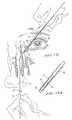
- a first embodiment of an intubation deviceThe lacrimal of the invention is shown in Figure 1.
- the apparatus 20is formed of silicone rubber and has a very large diameter segment 22 to a end.
- the expression "very large diameter”is used to signify that segment 22 has a outer diameter which is greater than the diameter maximum of other parts of the device that can pass easily in the canaliculi without damaging them.
- the canaliculiIn the in a typical adult patient, the canaliculi have an internal diameter of approximately 0.5 mm (0.01969 inch), and the maximum device diameter that can be passed in the canaliculi easily and without damaging these, is 1.346 mm (0.053 inch). In consequence the segment diameter of very large diameter 22 is greater than 1.346 mm.
- the outer segment diameter of very large diameter 22is 1.905 mm (0.075 inch); and segment 22 is 12 cm long (4.724 inches).
- the end 23 of segment 22is gently rounded.
- a light 37 of 0.635 mm diameteris formed, extending from end 23 to a point 37a at 5 mm from the opposite end of segment 22 or over the entire length of segment 22.
- segment 22is connected to one end of a central segment relatively thin 24, which has an outside diameter of 0.762 mm (0.030 inch) and a length of 20 mm (0.787 thumb).
- a segment central end 24rests against the eye in the canthus internally and in the canaliculi.
- the diameter of 0.762 mm of segment 24avoids irritation and defects epithelials that have been associated with segments of large diameter at this location and does not obstruct flow tears from the narrow canaliculi.
- the other end of the central segment 24is connected to one end of a medium diameter segment 26, the outer diameter of which can be passed within patient's canaliculi easily and without damaging the canaliculi.
- the outer diameter of the average diameter segment 26is 1.143 mm (0.045 inch) and the length of segment 26 is 15 cm (5,906 inches).
- the other end of the medium diameter segment 26is connected to one end of the distal segment 28.
- This segmenthas the same outside diameter of 0.762 mm (0.030 inch) than the central segment 24 and is 7cm (2.756 inches) in length, although the rest of the distal segment 28 is formed of solid silicone, a light 30 is formed within 3 cm (1.181 inches) distal to the segment distal 28.
- the light 30is therefore 3 cm long, extending from distal end 31 of the segment distal 28, and is delimited by a side wall 29 and has an inside diameter of 0.3302 mm (0.013 inch). However, the light 30 can also extend over the entire length of the distal segment 28.
- Softly tapered transition zones 32, 34 and 36which are 3 mm in length, respectively connect the very large diameter segment 22 to central segment 24, the central segment 24 to the medium diameter segment 26, and the medium diameter segment 26 to the distal segment 28.
- the prior art lacrimal intubation apparatusare tubular and the first embodiment of the apparatus 20 shown in Figure 1 is full silicone except the part of the distal segment 28 which contains the light 30.
- the deviceis full silicone except parts of the distal segment 28 and the very large diameter segment 22 which have lights 30 and 37, respectively.
- the lacrimal intubation apparatus 20 of Figure 1can be molded in its entirety. Thus, we realize a more reliable and economical manufacturing of the device and better compliance with the specifications of design.
- a molded devicealso has a smoother surface than the surface of an extruded device tubular.
- the apparatuscan also be realized according to another method which consists in molding only the the part of the device with the largest variation in diameter, the other parts being extruded.
- the central segment 24 and the transition segments adjacent 32 and 34are molded in one piece, while the very large diameter segment 22, the segment of average diameter 26, and the distal segment 28 are extruded in three additional pieces. The pieces are aligned in the correct order.
- the ends of the segment of very large diameter 22 and the transition segment 32are in stop at line 22a and are contained in a mold that properly fits the ends into stop with each other.
- ends of transition segment 34 and of segment mean diameter 26are in abutment at line 26a and are contained in a second mold which is engaged adjusted with segments 34 and 26.
- the distal segment 28 and the very large diameter segment 22are extruded under tube shape.
- a needleis inserted at the location of light 30, and the rest of the tube is filled with liquid silicone and left to solidify.
- Light 37 in the segment of very large diameter 22is formed in the same way. If the light must extend over the entire length of the segment, this step is omitted.
- the average diameter segment 26, which is shown as being full in Figure 1A,can also be extruded in the form of a tube.
- the light formed in this the lattercan extend over the entire length of the segment, whose light is closed by the transition 34 to the end 26a and by the transition 36 at the end 26b.
- a metal rod 38comprising a head 40, and a semi-rigid polyurethane sheath 42.
- the upper metallic 38is formed with a gently arched curve and has an outside diameter of about 0.6604 mm (0.026 inch).
- the rod 38 from the base of the head 40is 17.5 cm (6.89 inches) long.
- the head 40is 1 cm long and has a diameter of 1.016 mm (0.040 inch).
- Sheath 42is 17 cm (6.693 inches) long and has a very thin wall with an internal diameter of 0.889 mm (0.035 inch).
- the rod 38is inserted into the sheath 42 as shown in Figure 3. When the head is in stop with the end of the sheath 42, the section distal end 44 of stem 38 extends out of distal end of sheath 42 5 mm (0.1969 inch) and has a soft, slightly rounded blunt tip 45.
- the device insertion methodsput also using a metal probe 46 shown in FIG. 4.
- This probehas a 0.584 mm (0.023 inch) diameter and a distal portion 48 which has a diameter of 0.381 mm (0.015 inch) and a length of 10 mm (0.3937 inch).
- the proximal end 49 of probe 46is rounded, and the total length of the probe 46 is 19 cm (7.48 inches).
- the apparatus 20After the formation of a DCR hole between the bag tear and nasal cavity of the patient by endoscopy or by incision, the apparatus 20 is brought into place by the following methods.
- the surgeonpasses the rod 38 contained in sheath 42 by the upper lacrimal point 50, the upper canaliculus 52, the common canaliculus 55, the tear sac 54 and the patient's DCR 56 port in the patient's nasal cavity 58.
- the surgeongoes back into the nose (nasal cavity 58) and grips the end 44 of the metal rod 38 with a hemostat 60, taking care to place the hemostat 60 around the distal end section 44 of the stem metallic 38 only so as not to damage the sheath 42, and descends the stem of the nose until the distal end section 44 of the rod 38 is just outside of the patient's nostril 72.
- the surgeonthen pull the metal rod out in the opposite direction from the proximal end of the sheath 42 and withdraws it.
- Figure 8shows how the surgeon, in gripping the sheath 42 with one hand and the device 20 the other hand, then pull the sheath 42 up the nasal cavity 58 and out of the upper canaliculus 52 and upper lacrimal point 50.
- This maneuverpasses the distal segment 28 of the apparatus 20 through the orifice of DCR 56, the lacrimal sac 54, the common canaliculus 55, the superior canaliculus 52, and the superior lacrimal point 50.
- the surgeonthen removes the sheath 42 from the segment distal 28 and, as shown in Figure 9, grips the distal segment 28 and further withdraws device 20 from canaliculus 52 and the lacrimal point 50.
- the surgeonbends then the distal segment 28 of the apparatus 20 and, in holding the probe 46, pricking through the side wall 28 of the light 30 of the distal segment 28 with the part distal 48 of the probe 46 to form an opening 62 in a point 10 mm (0.3937 inch) from the distal end 31 of the distal segment 28.
- the distal part 48 of the probe 46is then passed through opening 62 until only 7 mm (0.2756 inch) of probe part 48 i.e. positioned in light 30, leaving a section 3 mm (0.1181 inch) distal 64 of occupied light by the probe.
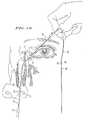
- Figure 13shows how the surgeon continues then pull the device 20 out of the nose. While the surgeon continues to shoot, as described on the figure 14, it passes the medium diameter segment 26 via the upper canaliculus 52, the lacrimal point upper 50, the lower lacrimal point 66, the lower canaliculus 68, the common canaliculus 55, the sac lacrimal 54 and DCR orifice 56 in the nasal cavity 58.
- the surgeoncontinues to pull until the very large diameter segment 22 is brought into position in the hole of DCR 56 with one end of segment 22 passed into the lacrimal sac 54 up to the level, but not in the tear sac end of the common canaliculus 55 and the opposite end in the nasal cavity 58.
- the average diameter segment 26is positioned in the orifice of DCR 56, one end being in the bag lacrimal 54 adjacent to the lacrimal sac end of the common canalicle 55 and the opposite end in the pit nasal 58.
- the central segment 24is positioned so to occupy the palpebral slit between the lacrimal points upper and lower 50 and 66 and in the canaliculi upper and lower 52 and 68 and the common canaliculus 55.
- a sutureis used to tie the ends segments 22 and 26 in the nasal cavity 58 one with the other.
- the two ends in the nasal cavityare then cut approximately 1 cm inside the nostril 72. This is the situation shown on the figure 15.
- This methodsolves several problems. She allows the very large diameter segment 22 to expand the orifice of DCR 56, despite the fact that a segment of a such a large diameter cannot be passed through canaliculi in the lacrimal sac 54. This is due to the fact that the end of the distal segment of the apparatus 20 is passed through the canaliculi from the nasal side, making useless for the very large segment 22 of a diameter of 1.905 mm the passage through the canaliculi of small diameter.
- the medium diameter segment 26 with a diameter of 1.143 mmis the largest at pass through the canaliculi, which it can cross easily, minimizing the risk of damage the canaliculi by stretching.
- segment average diameter 26passes through the canaliculi relatively easily, it is unlikely that the segment central 24 or the distal segment 28 of 0.762 mm breaks since segment 26 has passed within canaliculi. It should be appreciated that the implementation successfully the method is made possible by the structural configuration and special dimensions of the appliance 20.
- the alternative methodstarts in the same way as the method of figures 5 to 15.
- the surgeonpasses the rod 38 contained in the sheath 42 in the upper lacrimal point 50, the canaliculus superior 52, the common canaliculus 55, the lacrimal sac 54 and the patient's DCR 56 port in the nasal cavity of the patient 58.
- the metal rod 38is then lowered, as shown in Figure 6, until the end distal 44 of the rod 37 is just outside the nostril of patient 72.
- the surgeonpulls in the opposite direction the metal rod 38 outside the proximal end of the sheath 42 to remove it, leaving the sheath in place.
- the distal lumen 30 of the distal segment 28is crimped onto the fine distal part 48 of the probe metallic 46, as described in FIG. 16.
- the surgeonthreads the end 49 of probe 46 in the distal end of the sheath 42 until end 49 emerges from end proximal of the sheath 46 as described in FIG. 17.
- the surgeongrasps the end 49 of the probe 46 and further withdraws the probe 46 from the sheath 42, pulling thus the distal segment 28 crimped thereon with the apparatus 20 in the sheath 42.
- FIG. 18Arepresents, in an enlarged view, the distal segment 28 set on a fine distal part 48 of the probe 46 in the sheath 42.
- the surgeonpasses the end 49 of the probe 46 by the lacrimal point lower 66, the canaliculus lower 68, the canaliculus common 55, the lacrimal sac 54 and the orifice of DCR 56 in the nasal cavity.
- the surgeonthen goes up the pit nasal 58 with a hemostat 70 (see Figure 21) and grips probe 46. It then descends probe 46 with the distal segment 28 set with the device 20 from the pit nasal 58 and out of the nostril 72 (see Figure 22).
- the device 20can be made with distal segment 28 already crimped on part 48 of probe 46.
Landscapes
- Health & Medical Sciences (AREA)
- Ophthalmology & Optometry (AREA)
- Vascular Medicine (AREA)
- Life Sciences & Earth Sciences (AREA)
- Surgery (AREA)
- Engineering & Computer Science (AREA)
- Biomedical Technology (AREA)
- Heart & Thoracic Surgery (AREA)
- Plastic & Reconstructive Surgery (AREA)
- Nuclear Medicine, Radiotherapy & Molecular Imaging (AREA)
- Animal Behavior & Ethology (AREA)
- General Health & Medical Sciences (AREA)
- Public Health (AREA)
- Veterinary Medicine (AREA)
- Prostheses (AREA)
- Surgical Instruments (AREA)
Abstract
Description
Translated fromFrenchLa présente invention concerne un appareil d'intubationlacrymale en silicone et plus particulièrement unappareil asymétrique comprenant un segment de très granddiamètre qui est inséré de façon transnasale.The present invention relates to an intubation apparatussilicone lacrimal and more particularly aasymmetrical device comprising a segment of very largediameter which is inserted transnasally.
La glande lacrymale produit la couche aqueuse dufilm lacrymal. La partie orbitaire de la glande lacrymaleest située dans l'orbite temporale supérieure. Lescanalicules provenant de la glande lacrymale principaletraversent la glande lacrymale palpébrale adjacente pourdéboucher dans le cul-de-sac conjonctival supérieur quiest sur la face postérieure du haut de la paupièresupérieure. Les glandes lacrymales accessoires dans lespaupières supérieure et inférieure contribuent égalementà la production des larmes.The lacrimal gland produces the aqueous layer of thetear film. The orbital part of the lacrimal glandis located in the superior temporal orbit. Thecanaliculi from the main lacrimal glandcross the adjacent palpebral lacrimal gland tolead to the upper conjunctival cul-de-sac whichis on the posterior surface of the top of the eyelidsuperior. The accessory lacrimal glands in theupper and lower eyelids also contributeto the production of tears.
Les larmes imprègnent l'oeil et s'écoulent ensuitedans les points lacrymaux supérieur et inférieur, quisont situés sur les bords des paupières supérieure et inférieure internes. Les larmes s'écoulent ensuite parles canalicules supérieur et inférieur, le canaliculecommun, le sac lacrymal et descendent par le canalnasolacrymal dans le nez. Le canal nasolacrymal peut êtrebouché, de façon congénitale ou acquise à l'âge adulte.Si le canal nasolacrymal se bouche, les larmes ne peuventplus s'écouler de la surface de l'oeil par le systèmelacrymal dans le nez. Les larmes s'accumulent alors surles yeux et se répandent par dessus les paupières sur levisage. Le patient doit constamment se tamponner les yeuxavec un mouchoir. De plus, les larmes stagnent dans lesac lacrymal, ce qui permet aux bactéries de semultiplier. Le sac lacrymal alors s'infecte(dacryocystite). Sous l'effet de la dacryocystite, le saclacrymal devient enflé, rouge et douloureux. Du pussuinte depuis le sac lacrymal par le canalicule surl'oeil. Ceci conduit à ce que des matières purulentescouvrent constamment l'oeil. A la longue, la dacryocystitene répond pas aux antibiotiques et la chirurgie devientnécessaire.Tears permeate the eye and then flowin the upper and lower lacrimal points, whichare located on the edges of the upper eyelids andlower internal. The tears then flow outthe upper and lower canaliculi, the canaliculuscommon, the lacrimal sac and descend through the canalnasolacrimal in the nose. The nasolacrimal duct can beclogged, congenitally or acquired in adulthood.If the nasolacrimal duct becomes blocked, tears cannotmore flow from the surface of the eye through the systemlacrimal in the nose. Tears then accumulate oneyes and spread over the eyelids on theface. The patient must constantly dab his eyeswith a handkerchief. In addition, tears stagnate in thelacrimal sac, which allows bacteria to getmultiply. The lacrimal sac then becomes infected(dacryocystitis). Under the effect of dacryocystitis, the sacthe lacrimal becomes swollen, red and painful. Pusoozes from the lacrimal sac through the canaliculus ontothe eye. This leads to purulent substancesconstantly cover the eye. In the long run, dacryocystitisdoes not respond to antibiotics and surgery becomesnecessary.
La dacryocystorhinostomie (DCR) est l'opérationchirurgicale utilisée pour corriger l'obstruction ducanal nasolacrymal. Dans une DCR, une nouvelle ouverture(orifice) est formée entre le sac lacrymal et le nez.Celle-ci permet aux larmes de s'écouler depuis le saclacrymal par l'orifice de DCR dans le nez. Une DCRouverte ou par incision nécessite une incision sur lecôté du nez. Dans une DCR ouverte, un grand orifice deDCR est créé en faisant une ouverture de 17 mm et plusdans la muqueuse et l'os. Cette procédure est associée àune morbidité significative, une longue guérison, et lerisque de cicatrices et d'hémorragie. Par contre, une DCR endoscopique transnasale est associée à une morbiditébeaucoup plus faible, pas d'incision, et une durée deguérison rapide. Une DCR endoscopique peut être effectuéeà l'aide d'instruments de chirurgie lacrymale ousinusale, un laser ou un cathéter à ballonnet. L'orificede DCR endoscopique est plus petit (5 à 9 mm) que celuid'une DCR ouverte. Etant donné que l'orifice de DCR nefait que 5 à 9 mm (0,1969 à 0,354 pouce) de diamètre, unextenseur est requis pour maintenir l'orifice de DCRouvert après chirurgie. Sinon, l'inflammation et lacicatrisation post-opératoires peuvent provoquer safermeture.Dacryocystorhinostomy (DCR) is the operationused to correct the obstruction of thenasolacrimal duct. In a DCR, a new opening(orifice) is formed between the lacrimal sac and the nose.This allows tears to flow from the baglacrimal through the DCR orifice in the nose. A DCRopen or incision requires an incision on theside of the nose. In an open DCR, a large orificeDCR is created by making an opening of 17 mm and morein the mucosa and bone. This procedure is associated withsignificant morbidity, long healing, andrisk of scarring and hemorrhage. However, a DCRtransnasal endoscopy is associated with morbiditymuch lower, no incision, and a duration ofquick healing. Endoscopic DCR can be performedusing tear surgery instruments orsinus, laser or balloon catheter. The orificeof endoscopic DCR is smaller (5 to 9 mm) than thatof an open DCR. Since the DCR orifice does not5 to 9 mm (0.1969 to 0.354 inch) in diameter, aextender is required to maintain the DCR orificeopen after surgery. Otherwise, inflammation andpost-operative scarring can cause itsclosing.
Pour la sélection d'un appareil convenable, il estnécessaire de garder à l'esprit les dimensions etpropriétés des canalicules, qui forment la partie la plusétroite du système lacrymal, ainsi que les propriétés dumatériau de l'appareil de silicone et la technique d'insertionde l'appareil. Un patient adulte possède descanalicules qui font environ 0,5 mm (0,01969 pouce) dediamètre. Il est possible, cependant, d'utiliser desextenseurs en forme de tube de silicone qui sont quelquepeu plus grands en terme de diamètre extérieur, parcequ'ils possèdent un certain degré d'élasticité,et parce que les appareils d'intubation lacrymaletubulaires de silicone tendent à devenir plus finslorsqu'ils sont placés sous tension lorsqu'ils sontpassés dans le système lacrymal. La taille de l'appareild'intubation de silicone qui peut être utilisé atteint unelimite supérieure pour l'appareil d'intubation de diamètremaximal qui peut être passé dans les canalicules facilementet sans endommager ceux-ci.For the selection of a suitable device, it isnecessary to keep in mind the dimensions andproperties of the canaliculi, which form the mostthe lacrimal system, as well as the properties ofsilicone device material and insertion techniqueof the device. An adult patient hascanaliculi about 0.5 mm (0.01969 inch)diameter. It is possible, however, to usesilicone tube expanders which are somelittle bigger in terms of outside diameter, becausethat they have a certain degree of elasticity,and because the tear intubation devicestubular silicone tend to become thinnerwhen they are energized when they arepassed into the lacrimal system. The size of the devicesilicone intubation that can be used reaches aupper limit for the diameter airway devicemaximum which can be passed through the canaliculi easilyand without damaging them.
Le diamètre de l'appareil d'intubation lacrymale de diamètremaximal qui peut être utilisé ainsi est de 1,346 mm.The diameter of the diameter lacrimal intubation deviceThe maximum that can be used in this way is 1.346 mm.
Il a été proposé dans l'art antérieur d'utiliser unappareil tubulaire de silicone possédant un diamètreuniforme de 0,51 mm . Cependant, ceci est un diamètretrop faible pour maintenir l'orifice de DCR endoscopiqueouvert.It has been proposed in the prior art to use atubular silicone device with a diameter0.51 mm uniform. However, this is a diametertoo weak to maintain the endoscopic DCR orificeopen.
Un tube de plus grand diamètre possédant un diamètrede 0,94 mm a également été utilisé dans l'artantérieur. Ce tube de plus grand diamètre est encore troppetit et souple pour dilater l'orifice de DCR àballonnet. De plus, le diamètre maximal provoque desirritations et des défauts épithéliaux sur la cornée etla conjonctive à l'endroit où le tube repose contre l'oeildans le canthus interne. Il peut également obstruerl'écoulement par les canalicules étroits. Le tube desilicone comporte une sonde métallique rigide à chaqueextrémité. Pour placer le tube dans le système lacrymal,la sonde est passée par le point lacrymal, le canalicule,le sac lacrymal et l'orifice de DCR dans le nez. La sondeest saisie dans le nez et descendue dans le nez et horsde la narine. La sonde tire le tube de silicone connectépar le point lacrymal, le canalicule, le sac lacrymal etl'orifice de DCR dans le nez. Les deux extrémités du tubesont alors coupées à 1½ cm à l'intérieur de la narine. Letube est laissé en place pendant environ six mois.A larger diameter tube with a diameter0.94mm has also been used in the artprior. This larger diameter tube is still toosmall and flexible to expand the DCR orifice toballoon. In addition, the maximum diameter causesepithelial irritation and defects on the cornea andthe conjunctiva where the tube rests against the eyein the internal canthus. It can also obstructflow through narrow canaliculi. The tubesilicone has a rigid metal probe at eachend. To place the tube in the lacrimal system,the probe has passed through the lacrimal point, the canaliculus,the lacrimal sac and the DCR orifice in the nose. The probeis grabbed in the nose and lowered into the nose and outnostril. The probe pulls the connected silicone tubethrough the lacrimal point, the canaliculus, the lacrimal sac andthe DCR orifice in the nose. The two ends of the tubeare then cut to 1½ cm inside the nostril. Thetube is left in place for about six months.
Dans un effort pour dilater l'orifice de DCRendoscopique à l'aide d'un appareil d'intubation lacrmalede plus grand diamètre, qui est trop grand pour passerdans les canalicules, un appareil court, plus rigide, quipeut être placé depuis la fosse nasale a été proposé.L'appareil court de grand diamètre est poussé depuis l'intérieur du nez à travers l'orifice de DCRendoscopique dans le sac lacrymal. Une fois en place,l'appareil d'intubation lacrymale s'étend depuis le sac lacrymal,à travers l'orifice de DCR endoscopique, dans le nez.Un certain nombre de tels appareils ont été essayés. Ils posentplusieurs problèmes. Ils sont difficiles ou impossibles àpousser en place. Ils tombent fréquemment peu après lachirurgie. Des tentatives pour les fixer sur un tube desilicone ne sont que d'une aide minime. Ces appareilsd'intubation lacrymale peuvent provoquer des inflammations,des infections et des cicatrices.In an effort to dilate the DCR orificeendoscopic using a lacrimal intubation deviceof larger diameter, which is too large to passin the canaliculi, a short, more rigid device, whichcan be placed since the nasal cavity has been proposed.The short, large-diameter device is pushed frominside the nose through the DCR holeendoscopically in the lacrimal sac. Once in place,the lacrimal intubation apparatus extends from the lacrimal sac,through the endoscopic DCR hole, into the nose.A number of such devices have been tried. They putseveral problems. They are difficult or impossible topush in place. They frequently fall soon aftersurgery. Attempts to fix them on a tubesilicone are only of minimal help. These deviceslacrimal intubation can cause inflammation,infections and scars.
Le demandeur a conçu un tube de silicone "ventru"qui possède un grand diamètre dans la partie qui dilateun orifice de DCR à ballonnet. Un exemple est décrit dansla demande de brevet en cours d'examen n°08/547 792, déposée le 25 octobre 1995. Il possède unfaible diamètre dans le segment qui repose contre l'oeil.La partie de grand diamètre (généralement de 1,32 mm.de diamètre) ne peut pas être passée par le pointlacrymal et les canalicules de faible diamètre sansglisser de la sonde. par conséquent, chaque extrémité dutube comprend une longue partie de faible diamètre. Lesextrémités de faible diamètre du tube sont fixées à lasonde. Une fois que la sonde est saisie dans le nez, elleest descendue dans le nez et l'extrémité de faiblediamètre du tube liée passe par le point lacrymal, lescanalicules, le sac lacrymal et l'orifice de DCR àballonnet dans le nez. Ceci est effectué avec chaqueextrémité du tube. Une fois en place, les extrémités dutube sont coupées à 1½ cm à l'intérieur de la narine. Lesegment de plus grand diamètre du tube doit être situédans les canalicules distaux, le sac lacrymal et l'orifice de DCR à ballonnet s'étendant dans le nez.L'extrémité de faible diamètre du tube doit êtredécoupée.The applicant has designed a "potbellied" silicone tubewhich has a large diameter in the part which expandsa balloon DCR port. An example is described inpatent application under examination no.08/547 792, filed on October 25, 1995. It has asmall diameter in the segment which rests against the eye.The part of large diameter (usually 1.32 mm.in diameter) cannot be passed through the pointlacrimal and small diameter canaliculi withoutslide from the probe. therefore, each end of thetube includes a long portion of small diameter. Thesmall diameter tube ends are attached to theprobe. Once the probe is entered into the nose, itwent down into the nose and the tip of weakdiameter of the linked tube passes through the lacrimal point,canaliculi, the lacrimal sac and the DCR orifice atballoon in the nose. This is done with eachend of the tube. Once in place, the ends of thetube are cut to 1½ cm inside the nostril. Thelarger diameter segment of the tube should be locatedin the distal canaliculi, the lacrimal sac andthe balloon DCR orifice extending into the nose.The small diameter end of the tube should becut out.
Cependant, il existe deux problèmes avec ce tube"ventru". Chez certains patients, il peut être difficilede tirer les segments de grand diamètre à travers lescanalicules. Si les canalicules sont quelque peu étroits,les tubes peuvent se rompre lorsque le chirurgien exerceune traction sur le segment distal étroit dans le nez ententant de passer le gros segment par les canaliculesdans le sac lacrymal. Un deuxième problème est que lepassage des segments de grand diamètre dans lescanalicules peut étirer suffisamment les canalicules pourles endommager et provoquer des fibroses (cicatrices).Dans ce cas, les canalicules deviennent sténosés(étroits) et obstruent l'écoulement des larmes une foisque le tube est retiré. Ceci provoque des larmoiements.De plus, un tube d'un diamètre de plus de 1,35 mm estnécessaire pour dilater l'orifice de DCR à ballonnet danscertains cas. Cependant, comme il a été expliqué, il estimpossible de faire passer un tube d'un diamètre beaucoupplus grand que 1,35 mm par les canalicules dans lesac lacrymal.However, there are two problems with this tube."potbellied". In some patients it may be difficultpull the large diameter segments through thecanaliculi. If the canaliculi are somewhat narrow,the tubes can break when the surgeon exercisestraction on the narrow distal segment in the nosetrying to pass the large segment through the canaliculiin the lacrimal sac. A second problem is that thepassage of large diameter segments incanaliculi can stretch the canaliculi enough todamage them and cause fibrosis (scarring).In this case, the canaliculi become stenosed(narrow) and obstruct the flow of tears oncethat the tube is removed. This causes tearing.In addition, a tube with a diameter of more than 1.35 mm isnecessary to dilate the balloon DCR orifice incertain cases. However, as has been explained, it isimpossible to pass a tube with a large diameterlarger than 1.35 mm by the canaliculi in thetear bag.
Si un tube de silicone peut être passé dans lecanalicule depuis la cavité nasale, un tube d'un diamètrebeaucoup plus grand peut être utilisé. Cependant, pendantla chirurgie, il n'est généralement pas possible de voirle canalicule commun depuis l'intérieur du nez, mêmevisualisé à l'aide d'un endoscope. Il n'est certainementpas possible d'enfiler un tube de silicone depuis le nezdans le petit canalicule commun. Pour cette raison, l'intubation de silicone depuis le nez jusqu'au saclacrymal par les canalicules n'a jamais été effectuée.If a silicone tube can be passed through thecanaliculus from the nasal cavity, a tube with a diametermuch larger can be used. However, duringsurgery it is usually not possible to seethe common canaliculus from inside the nose, evenviewed using an endoscope. It is certainlynot possible to thread a silicone tube from the nosein the small common canaliculus. For this reason,silicone intubation from the nose to the baglacrimal from the canaliculi was never performed.
Une proposition initiale d'insérer une grande canuledans le système lacrymal est décrite dans le brevet U.S.n° 2 154 968. Ce brevet propose l'utilisation d'unecanule en spirale en fil métallique fin, dont le diamètreexterne peut varier jusqu'à 5/32 pouce. La spirale esteffilée à une extrémité pour faciliter l'insertion dansle conduit lacrymal. Un tube est inséré à travers lepoint lacrymal, le canalicule, le sac lacrymal et lecanal nasolacrymal dans la fosse nasale, et un fil estenfilé dans le tube. L'extrémité du fil est tirée hors dela narine et la canule en spirale est enfilée sur le filavec son extrémité effilée tournée vers le haut. Uneenveloppe de support est placée sur le fil et la canuleest remontée dans le canal nasolacrymal depuis la fossenasale. Cependant, la canule du brevet 2 154 968 n'est pasun appareil d'intubation lacrymale, c'est un conduit.An initial proposal to insert a large cannulain the lacrimal system is described in U.S. patentNo. 2,154,968. This patent proposes the use of aspiral cannula made of fine metal wire, the diameter of whichexternal can vary up to 5/32 inch. The spiral istapered at one end for easy insertion intothe tear duct. A tube is inserted through thelacrimal point, canaliculus, lacrimal sac andnasolacrimal duct in the nasal cavity, and a thread isthreaded into the tube. The end of the wire is pulled out ofthe nostril and the spiral cannula is threaded on the wirewith its tapered end facing up. Asupport envelope is placed on the wire and the cannulaascended into the nasolacrimal duct from the fossanasal. However, the cannula of patent 2,154,968 is nota tear intubation device, it's a conduit.
Cette canule est constituée d'unmétal rigide, non de silicone. La canule n'est pas placéedans un orifice chirurgical formé pour drainer les larmesdans la fosse nasale. En fait, la proposition n'est pascliniquement viable. Elle conduirait à des infections etdes lésions chroniques et le canal se refermerait aprèsle retrait de la canule en spirale. De plus, la procédureproposée dans le brevet 2 154 968 serait très difficile àeffectuer pour un chirurgien. Par exemple, le chirurgienne serait pas en mesure de voir si la canule estcorrectement positionnée, parce que la visualisation ducanal nasolacrymal est bouchée par le cornet inférieur.This cannula consists of arigid metal, not silicone. Cannula is not placedin a surgical opening formed to drain tearsin the nasal cavity. In fact, the proposal is notclinically viable. It would lead to infections andchronic lesions and the canal would close afterwithdrawal of the spiral cannula. In addition, the procedureproposed in patent 2,154,968 would be very difficult toperform for a surgeon. For example, the surgeonwouldn't be able to see if the cannula iscorrectly positioned, because the visualization of thenasolacrimal duct is blocked by the lower horn.
Le brevet U.S. n° 5 437 625 décrit un dispositifsous la forme d'un seul tube de silicone flexible comprenant un segment central souple et plus fin et unepaire de segments terminaux de plus grand diamètre avecdes extrémités libres qui sont pointues et hermétiques.Les segments terminaux comportent des petites coupuresqui reçoivent des sondes métalliques s'étendant dans lesextrémités fermées au cours de l'intubation. Il a étéobservé que les extrémités pointues des segmentsterminaux, étant rigides et dures, sont traumatisantes etsont trop dommageables pour les canalicules.U.S. Patent No. 5,437,625 describes a deviceas a single flexible silicone tubecomprising a flexible and thinner central segment and apair of larger diameter end segments withfree ends which are pointed and hermetic.Terminal segments have small cutswhich receive metallic probes extending into theends closed during intubation. He wasobserved that the pointed ends of the segmentsterminals, being rigid and hard, are traumatic andare too damaging to the canaliculi.
Le brevet U.S. n° 4 305 395 décrit l'utilisation desondes métalliques insérées dans des ouvertures dans lesparois latérales de gaines tubulaires en polyamide fixéesaux extrémités d'une longueur de tubulure en caoutchoucsilicone. Les extrémités des sondes sont en butée contreles extrémités distales fermées des gaines tubulaires. Latubulure est ensuite positionnée dans le système lacrymalen passant les sondes insérées dans les gaines dans lesystème lacrymal par dessus le nez. Les sondes sontretirées, et les gaines sont saisies et tirées pourpositionner la tubulure dans le système lacrymal.U.S. Patent No. 4,305,395 describes the use ofmetal probes inserted into openings in theside walls of fixed polyamide tubular sheathsat the ends of a length of rubber tubingsilicone. The ends of the probes are in abutment againstthe closed distal ends of the tubular sheaths. Thetubing is then positioned in the lacrimal systempassing the probes inserted in the sheaths in thelacrimal system over the nose. The probes areremoved, and the sleeves are gripped and pulled toposition the tubing in the lacrimal system.
Le brevet U.S. n° 4 380 239 est un autre exemple del'utilisation de sondes pour l'intubation d'un tube encaoutchouc silicone. Les sondes, qui sont formées de fild'acier, sont insérées dans l'extrémité ouverte du tubepour faciliter l'insertion du tube dans un canaliculedans le conduit lacrymal.Another example is U.S. Patent No. 4,380,239.the use of probes for the intubation of a tube insilicone rubber. The probes, which are formed from wiresteel, are inserted into the open end of the tubeto facilitate insertion of the tube into a canaliculusin the lacrimal duct.
Dans les méthodes des brevets 4 305 395 et 4 380239, les gaines ou sondes doivent être tirées depuis lanarine et, pendant la procédure, des épistaxies et desfractures osseuses du cornet inférieur se produisentparfois.In patent methods 4,305,395 and 4,380239, the sheaths or probes must be drawn from thenostril and, during the procedure, epistaxies andbone fractures of the lower cornet occursometimes.
Les appareils d'intubation lacrymale de silicone del'art antérieur sont tubulaires. Etant donné qu'un tube nepeut être fabriqué que par un procédé de moulage lorsque letube entier est d'un diamètre uniforme, un tube de diamètrevariable ne peut être fabriqué que par un procédéd'extrusion. Le procédé d'extrusion, moins fiable, permetde fabriquer des tubes si la variation de diamètre estminime. Cependant, l'extrusion seule n'est pas un procédéréalisable si, comme dans la présente invention, il existeune forte variation du diamètre des segments de l'appareil.De plus, des appareils extrudés tubulaires possèdent unesurface qui est plus rugueuse que la surface possible d'unappareil moulé. Le procédé d'extrusion est égalementcoûteux, parce qu'un pourcentage significatif des tubesextrudés n'est pas conforme au diamètre spécifié et doitêtre rejeté.The silicone lacrimal intubation devices ofthe prior art are tubular. Since a tube does notcan only be manufactured by a molding process when thewhole tube is of uniform diameter, tube of diametervariable can only be produced by a processextrusion. The less reliable extrusion process allowsto make tubes if the diameter variation isminimal. However, extrusion alone is not a processfeasible if, as in the present invention, there area large variation in the diameter of the device segments.In addition, tubular extruded devices have asurface which is rougher than the possible surface of amolded device. The extrusion process is alsoexpensive, because a significant percentage of the tubesextruded does not conform to the specified diameter and mustbe rejected.
L'objet de l'invention est de proposer un nouveautype d'appareil d'intubation lacrymale comportant unsegment terminal de très grand diamètre qui possède undiamètre extérieur supérieur au diamètre des autres partiesafin de pouvoir passer dans les canalicules facilement etsans endommager ceux-ci.The object of the invention is to propose a newtype of tear intubation device withvery large diameter terminal segment which has aouter diameter greater than the diameter of the other partsso that you can pass through the canaliculi easily andwithout damaging them.
Suivant un premier mode de réalisation, l'appareild'intubation lacrymale de l'invention comprend un élémentde silicone souple allongé comportant un segment terminalde très grand diamètre, possédant un diamètre extérieursupérieur au diamètre maximal des autres parties quipeuvent passer dans les canalicules du patient facilementet sans endommager ces derniers, c'est-à-dire, supérieur à1,346 mm et inférieur au diamètre intérieur d'un orifice deDCR formé entre le sac lacrymal et la fosse nasale. L'appareil se présente sous la forme d'un élément allongéqui comprend des segments supplémentaires avec desdiamètres extérieurs qui sont inférieurs à 1,346 mm. Lessegments supplémentaires comprennent un segment centralrelativement fin, qui doit reposer sur l'oeil entre lespoints lacrymaux et dans les canalicules une fois quel'appareil est installé. Une extrémité du segment centralest connectée à une extrémité du segment terminal de trèsgrand diamètre par l'intermédiaire d'un segment detransition court. L'autre extrémité du segment central estconnectée par l'intermédiaire d'un deuxième segment detransition court à une extrémité d'un segment de diamètremoyen, l'autre extrémité de ce dernier étant connectée à unsegment distal.According to a first embodiment, the devicetear intubation of the invention comprises an elementflexible elongated silicone with a terminal segmentvery large diameter, with an outer diametergreater than the maximum diameter of the other parts whichcan pass through the patient's canaliculi easilyand without damaging them, that is to say, greater than1.346 mm and less than the inside diameter of aDCR formed between the lacrimal sac and the nasal cavity.The device is in the form of an elongated elementwhich includes additional segments withoutside diameters which are less than 1.346 mm. Theadditional segments include a central segmentrelatively thin, which should rest on the eye between thetear points and in the canaliculi oncethe device is installed. One end of the central segmentis connected to one end of the terminal segment of verylarge diameter through a segment ofshort transition. The other end of the central segment isconnected via a second segment ofshort transition at one end of a segment of diametermedium, the other end of the latter being connected to adistal segment.
Une lumière peut s'étendre de l'extrémité distale del'élément à mi-chemin de la longueur du segment distal. Lereste de l'élément comprenant le reste du segment distal,le segment de diamètre moyen, les segments de transition,le segment central et le segment terminal de très granddiamètre sont tous pleins.A light can extend from the distal end ofthe element halfway along the length of the distal segment. Therest of the element including the rest of the distal segment,the medium diameter segment, the transition segments,the central segment and the terminal segment of very largediameter are all full.
Dans un mode de réalisation préféré, le segmentterminal de très grand diamètre possède un diamètreextérieur de 1,905 mm.In a preferred embodiment, the segmentvery large diameter terminal has a diameter1.905 mm outside.
Dans un deuxième mode de réalisation de l'appareild'intubation lacrymale, la flexibilité du segment de trèsgrand diamètre est augmentée par une lumière s'étendant del'extrémité libre du segment de très grand diamètre jusqu'àun point situé au voisinage du premier segment detransition. Etant donné la structure sensiblement pleinedes appareils de ces modes de réalisation, sauf pour les lumières dans leurs segments distaux, et dans le cas dudeuxième mode de réalisation, la lumière dans son segmentde très grand diamètre, il est possible de fabriquer defaçon économique l'appareil entier par un procédé demoulage. Sinon, l'appareil peut être fabriqué par unprocédé dans lequel seule la partie présentant la plusforte variation de diamètre - le segment central fin et lessegments de transition à chacune de ses extrémités - estmoulée. Les segments de très grand diamètre, de diamètremoyen et distaux sont extrudés et les pièces séparées sontsoudées les unes aux autres en injectant de la siliconeliquide à toutes les jonctions.In a second embodiment of the apparatustear intubation, the flexibility of the segment of verylarge diameter is increased by a light extending fromthe free end of the very large diameter segment up toa point located near the first segment oftransition. Given the substantially full structuredevices of these embodiments, except forlights in their distal segments, and in the case of thesecond embodiment, light in its segmentvery large diameter, it is possible to manufactureeconomically the entire device by a process ofmolding. Otherwise, the device can be manufactured by aprocess in which only the party presenting the mostlarge variation in diameter - the thin central segment and thetransition segments at each of its ends - ismolded. Very large diameter segments, diametermiddle and distal are extruded and the separate pieces arewelded together by injecting siliconeliquid at all junctions.
L'invention va maintenant être décrite avec plus dedétails en se référant à des modes de réalisationparticuliers, donnés à titre d'exemple seulement etreprésentés aux dessins annexés.
Un premier mode de réalisation d'un appareil d'intubationlacrymale de l'invention est représenté figure 1.L'appareil 20 est formé de caoutchouc silicone et comporte un segment de très grand diamètre 22 à uneextrémité. L'expression "très grand diamètre" estutilisée pour signifier que le segment 22 possède undiamètre extérieur qui est supérieur au diamètremaximal des autres parties de l'appareil qui peuvent passerfacilement dans les canalicules sans les endommager. Dans lecas d'un patient adulte type, les canalicules possèdentun diamètre intérieur d'environ 0,5 mm (0,01969 pouce),et le diamètre maximal d' appareil qui peut être passédans les canalicules facilement et sans endommagerceux-ci, est de 1,346 mm (0,053 pouce). Enconséquence, le diamètre de segment de très granddiamètre 22 est supérieur à 1,346 mm. Dans un mode deréalisation préféré, le diamètre extérieur de segment detrès grand diamètre 22 est de 1,905 mm (0,075 pouce) ; etle segment 22 fait 12 cm de long (4,724 pouces).L'extrémité 23 du segment 22 est doucement arrondie. Afind'augmenter la flexibilité du segment 22, dans undeuxième mode de réalisation de l'appareil 20 représentésur la figure 1A, une lumière 37 de 0,635 mm dediamètre est formée, s'étendant de l'extrémité 23 à unpoint 37a à 5 mm de l'extrémité opposée du segment 22 ousur toute la longueur du segment 22.A first embodiment of an intubation deviceThe lacrimal of the invention is shown in Figure 1.The
Dans les deux modes de réalisation représentés surles figures 1 et 1A, l'autre extrémité du segment 22 estconnectée à une extrémité d'un segment centralrelativement fin 24, qui possède un diamètre extérieur de0,762 mm (0,030 pouce) et une longueur de 20 mm (0,787pouce). Une fois que l' appareil est installé, un segmentcentral fin 24 repose contre l'oeil dans le canthusinterne et dans les canalicules. Le diamètre de 0,762mm du segment 24 évite les irritations et défauts épithéliaux qui ont été associés aux segments de granddiamètre à cet emplacement et n'obstrue pas l'écoulementdes larmes par les canalicules étroits.In the two embodiments shown inFigures 1 and 1A, the other end of
L'autre extrémité du segment central 24 estconnectée à une extrémité d'un segment de diamètre moyen26, dont le diamètre extérieur peut être passé dans lescanalicules du patient facilement et sans endommager lescanalicules. Dans le mode de réalisation préféré, lediamètre extérieur du segment de diamètre moyen 26 est de1,143 mm (0,045 pouce) et la longueur du segment 26 estde 15 cm (5,906 pouces).The other end of the
L'autre extrémité du segment de diamètre moyen 26est connectée à une extrémité du segment distal 28. Cesegment possède le même diamètre extérieur de 0,762 mm(0,030 pouce) que le segment central 24 et fait 7cm (2,756pouces) de longueur, bien que le reste du segment distal28 soit formé de silicone pleine, une lumière 30 estformée dans les 3 cm (1,181 pouces) distaux du segmentdistal 28. La lumière 30 fait donc 3 cm de long,s'étendant depuis l'extrémité distale 31 du segmentdistal 28, et est délimitée par une paroi latérale 29 etpossède un diamètre intérieur de 0,3302 mm (0,013 pouce).Cependant la lumière 30 peut également s'étendre surtoute la longueur du segment distal 28.The other end of the
Des zones de transition doucement effilées 32, 34 et36, qui font 3 mm de longueur, relient respectivement lesegment de très grand diamètre 22 au segment central 24,le segment central 24 au segment de diamètre moyen 26, etle segment de diamètre moyen 26 au segment distal 28.Softly tapered
Les appareilsd'intubation lacrymale de l'art antérieursont tubulaires et le premier mode de réalisation de l'appareil20 représenté sur la figure 1 est de silicone pleine sauf la partie du segment distal 28 qui comporte lalumière30. Dans le deuxième mode de réalisation, l'appareilest de silicone pleine sauf les parties du segment distal28 et du segment de très grand diamètre 22 quicomportent les lumières 30 et 37, respectivement.The prior art lacrimal intubation apparatusare tubular and the first embodiment of the
Etant donné la grande variation des diamètresextérieurs des segments de l'appareil 20, il n'est paspossible de former celui-ci par extrusion.L'appareil d'intubation lacrymale 20 de la figure 1 peut êtremoulé dans son intégralité. Ainsi, on réalise unefabrication plus fiable et économique de l'appareil etune meilleure conformité aux spécifications deconception. Un appareil moulé possède également unesurface plus lisse que la surface d'un appareil extrudétubulaire.Given the large variation in diametersoutside of the segments of the
Cependant, l' appareil peut également être réalisésuivant une autre méthode qui consiste à ne mouler que lapartie de l' appareil qui présente la plus grandevariation de diamètre, les autres parties étantextrudées. En particulier, comme décrit sur la figure 1A,le segment central 24 et les segments de transitionadjacents 32 et 34 sont moulés en une pièce, tandis quele segment de très grand diamètre 22, le segment dediamètre moyen 26, et le segment distal 28 sont extrudésen trois pièces supplémentaires. Les pièces sont alignéesdans l'ordre approprié. Les extrémités du segment de trèsgrand diamètre 22 et du segment de transition 32 sont enbutée au niveau de la ligne 22a et sont contenues dans unmoule qui met en prise de façon ajustée les extrémités enbutée l'une avec l'autre. De façon similaire, lesextrémités du segment de transition 34 et du segment dediamètre moyen 26 sont en butée au niveau de la ligne 26a et sont contenues dans un deuxième moule qui est en prisede façon ajustée avec les segments 34 et 26. De lasilicone liquide est injectée dans le deuxième moule etest solidifiée pour souder les extrémités en butée l'uneavec l'autre. L'autre extrémité 26b du segment dediamètre moyen 26 est alignée avec, mais espacée del'extrémité 28a du segment distal 28. Un troisième moulemet en prise de façon ajustée les extrémités adjacentes26b et 28a des segments 26 et 28 et contient lesextrémités 26b et 28a et l'espacement entre celles-ci. Dela silicone liquide est injectée dans le moule,remplissant l'espacement, et se solidifie pour former unsegment de transition 36 et souder les segments 26 et 28l'un avec l'autre. Il est également possible d'omettrel'espacement, mettre en butée les extrémités 28a et 26b,et former un segment de transition 36 dans le troisièmemoule autour de l'extrémité du segment 28 lorsque lesextrémités 28a et 26b sont soudées l'une avec l'autre.Bien que ces techniques résultent en des segments detransition 36 qui ne font qu'approcher la configurationdoucement effilée des segments de transition 32 et 34, laforme du segment de transition 36 n'est pas critique etune surface inexacte sur le segment 36 ne doit pasinterférer avec le fonctionnement de l' appareil 20.However, the apparatus can also be realizedaccording to another method which consists in molding only thethe part of the device with the largestvariation in diameter, the other parts beingextruded. In particular, as described in Figure 1A,the
Dans une autre méthode, le segment distal 28 et lesegment de très grand diamètre 22 sont extrudés sousforme de tubes. Afin de former une lumière 30 dans lesegment distal 28, une aiguille est insérée àl'emplacement de la lumière 30, et le reste du tube estrempli avec de la silicone liquide et laissée àsolidifier. La lumière 37 dans le segment de très granddiamètre 22 est formée de la même façon. Si la lumière doit s'étendre sur toute la longueur du segment, cetteétape est omise.In another method, the
Le segment de diamètre moyen 26, qui est représentécomme étant plein sur la figure 1A, peut également êtreextrudé sous forme de tube. La lumière formée dans cedernier peut s'étendre sur toute la longueur du segment,dont la lumière est fermée par la transition 34 àl'extrémité 26a et par la transition 36 à l'extrémité26b.The
Les procédés d'insertion de l'appareil 20 dans lesystème lacrymal du patient nécessitent certains outilsspéciaux. Comme décrit sur la figure 2, ceux-cicomprennent une tige métallique 38, comportant une tête40, et une gaine en polyuréthane semi-rigide 42. La tigemétallique 38 est formée avec une courbe doucement arquéeet possède un diamètre extérieur d'environ 0,6604 mm(0,026 pouce). La tige 38 à partir de la base de la tête 40fait 17,5 cm (6,89 pouces) de long. La tête 40 fait 1 cmde long et possède un diamètre de 1,016 mm (0,040 pouce).La gaine 42 fait 17 cm (6,693 pouces) de long et comporteune paroi très fine avec un diamètre intérieur de 0,889mm (0,035 pouce). La tige 38 est insérée dans la gaine 42comme décrit sur la figure 3. Lorsque la tête est enbutée avec l'extrémité de la gaine 42, la sectionterminale distale 44 de la tige 38 s'étend hors del'extrémité distale de la gaine 42 de 5 mm (0,1969 pouce)et comporte une pointe émoussée légèrement arrondie douce45.The methods of inserting the
Les méthodes d'insertion de l' appareil mettentégalement en oeuvre l'utilisation d'une sonde métallique46 représentée sur la figure 4. Cette sonde possède undiamètre de 0,584 mm (0,023 pouce) et une partie distale 48 qui possède un diamètre de 0,381 mm (0,015 pouce) et unelongueur de 10 mm (0,3937 pouce) . L'extrémité proximale49 de la sonde 46 est arrondie, et la longueur totale dela sonde 46 est de 19 cm (7,48 pouces).The device insertion methods putalso using a
Après la formation d'un orifice de DCR entre le saclacrymal et la fosse nasale du patient par endoscopie oupar incision, l'appareil 20 est amené en place parles méthodes suivantes.After the formation of a DCR hole between the bagtear and nasal cavity of the patient by endoscopy orby incision, the
En référence à la figure 5, selon un premier mode deréalisation de la méthode, le chirurgien passe la tige 38contenue dans la gaine 42 par le point lacrymal supérieur50, le canalicule supérieur 52, le canalicule commun 55,le sac lacrymal 54 et l'orifice de DCR 56 du patient dansla fosse nasale 58 du patient. Comme décrit sur la figure6, le chirurgien remonte dans le nez (fosse nasale 58) etsaisit l'extrémité 44 de la tige métallique 38 avec unhémostat 60, en prenant soin de placer l'hémostat 60autour de la section terminale distale 44 de la tigemétallique 38 uniquement afin de ne pas endommager lagaine 42, et descend la tige du nez jusqu'à ce que lasection terminale distale 44 de la tige 38 soit juste àl'extérieur de la narine 72 du patient. Le chirurgientire ensuite dans le sens inverse la tige métallique horsde l'extrémité proximale de la gaine 42 et la retire.With reference to FIG. 5, according to a first mode ofcarrying out the method, the surgeon passes the
Comme décrit sur la figure 7, le chirurgien enfileensuite l'extrémité distale 28 de l'appareil de silicone20 dans l'extrémité distale de la gaine 42 de plusieurscentimètres. La figure 8 montre comment le chirurgien, ensaisissant la gaine 42 d'une main et l'appareil 20 del'autre main, tire ensuite la gaine 42 en remontant lafosse nasale 58 et hors du canalicule supérieur 52 et dupoint lacrymal supérieur 50. Cette manoeuvre fait passer le segment distal 28 de l'appareil 20 par l'orifice deDCR 56, le sac lacrymal 54, le canalicule commun 55, lecanalicule supérieur 52, et le point lacrymal supérieur50. Le chirurgien retire ensuite la gaine 42 du segmentdistal 28 et, comme décrit sur la figure 9, saisit lesegment distal 28 et retire plus avant l'appareil 20 ducanalicule 52 et du point lacrymal 50.As described in Figure 7, the surgeon puts onthen the
Comme décrit sur la figure 10, le chirurgien plieensuite le segment distal 28 de l'appareil 20 et, entenant la sonde 46, pique à travers la paroi latérale 28de la lumière 30 du segment distal 28 avec la partiedistale 48 de la sonde 46 pour former une ouverture 62 enun point à 10 mm (0,3937 pouce) de l'extrémité distale 31du segment distal 28. La partie distale 48 de la sonde 46est ensuite passée dans l'ouverture 62 jusqu'à ce queseulement 7 mm (0,2756 pouce) de partie de sonde 48 soitpositionnée dans la lumière 30, laissant une sectiondistale 64 de 3 mm (0,1181 pouce) de la lumière occupéepar la sonde.As depicted in Figure 10, the surgeon bendsthen the
Comme décrit sur la figure 11 et le détail agrandide la figure 11A, l'extrémité de la partie distale 48 dela sonde 46 étant insérée à travers la paroi latérale 29dans la lumière 30, le chirurgien passe la sonde 46 dansle point lacrymal inférieur 66, le canalicule inférieur68, le canalicule commun 55, le sac lacrymal 54 etl'orifice de DCR 56 dans la fosse nasale 58.As described in Figure 11 and the enlarged detailof FIG. 11A, the end of the
Le chirurgien remonte ensuite la fosse nasale 58avec un hémostat 70 (voir figure 12) et saisit la sectionterminale 64 du segment distal 28 et descend l'appareil20 dans la fosse nasale et hors de la narine 72.Parallèlement, le chirurgien remonte la sonde 46, hors dupoint lacrymal 66 pour la retirer de la lumière 30.The surgeon then raises the
La figure 13 montre comment le chirurgien continueensuite de tirer l' appareil 20 hors du nez. Pendant quele chirurgien continue de tirer, comme décrit sur lafigure 14, il fait passer le segment de diamètre moyen 26par le canalicule supérieur 52, le point lacrymalsupérieur 50, le point lacrymal inférieur 66, lecanalicule inférieur 68, le canalicule commun 55, le saclacrymal 54 et l'orifice DCR 56 dans la fosse nasale 58.Figure 13 shows how the surgeon continuesthen pull the
Le chirurgien continue de tirer jusqu'à ce que lesegment de très grand diamètre 22 soit amené en positiondans l'orifice de DCR 56 avec une extrémité du segment 22passée dans le sac lacrymal 54 jusqu'au niveau, mais pasdans l'extrémité côté sac lacrymal du canalicule commun55 et l'extrémité opposée dans la fosse nasale 58. Lesegment de diamètre moyen 26 est positionné dansl'orifice de DCR 56, une extrémité étant dans le saclacrymal 54 adjacente à l'extrémité côté sac lacrymal ducanalicule commun 55 et l'extrémité opposée dans la fossenasale 58. Le segment central 24 est positionné de façonà occuper la fente palpébrale entre les points lacrymauxsupérieur et inférieur 50 et 66 et dans les canaliculessupérieur et inférieur 52 et 68 et le canalicule commun55.The surgeon continues to pull until thevery
Une suture est utilisée pour nouer les extrémitésdes segments 22 et 26 dans la fosse nasale 58 l'une avecl'autre. Les deux extrémités dans la fosse nasale sontensuite découpées d'environ 1 cm à l'intérieur de lanarine 72. Ceci est la situation représentée sur lafigure 15.A suture is used to tie the
Cette méthode résout plusieurs problèmes. Ellepermet au segment de très grand diamètre 22 de dilaterl'orifice de DCR 56, malgré le fait qu'un segment d'un diamètre aussi grand ne peut pas être passé par lescanalicules dans le sac lacrymal 54. Ceci est dû au faitque l'extrémité du segment distal de l' appareil 20 estpassée par les canalicules depuis le côté nasal, rendantinutile pour le segment de très grand diamètre 22 d'undiamètre de 1,905 mm le passage par les canalicules defaible diamètre. Le segment de diamètre moyen 26possédant un diamètre de 1,143 mm est le plus grand àpasser par les canalicules, qu'il peut traverserfacilement, réduisant au minimum le risque d'endommagerles canalicules par étirement. Etant donné que le segmentde diamètre moyen 26 passe dans les canaliculesrelativement aisément, il est improbable que le segmentcentral 24 ou le segment distal 28 de 0,762 mm secasse étant donné que le segment 26 est passé dans lescanalicules. Il doit être apprécié que la mise en oeuvreavec succès de la méthode est rendue possible par laconfiguration structurale et les dimensions particulièresde l'appareil 20.This method solves several problems. Sheallows the very
Un deuxième mode de réalisation alternatif d'uneméthode d'insertion de l'appareil d'intubation lacrymale del'invention est décrit ci-après en référence aux figures16 à 23.A second alternative embodiment of amethod of inserting the tear intubation devicethe invention is described below with reference to the figures16 to 23.
La méthode alternative commence de la même façon quela méthode des figures 5 à 15. Comme décrit sur la figure5, le chirurgien passe la tige 38 contenue dans la gaine42 dans le point lacrymal supérieur 50, le canaliculesupérieur 52, le canalicule commun 55, le sac lacrymal 54et l'orifice DCR 56 du patient dans la fosse nasale dupatient 58. La tige métallique 38 est ensuite descendue,comme décrit sur la figure 6, jusqu'à ce que l'extrémitédistale 44 de la tige 37 soit juste à l'extérieur de la narine du patient 72. Le chirurgien tire en sens inversela tige métallique 38 hors de l'extrémité proximale de lagaine 42 pour la retirer, laissant la gaine en place.The alternative method starts in the same way asthe method of figures 5 to 15. As described in the figure5, the surgeon passes the
Une fois que la gaine est en place, selon la méthodealternative, la lumière distale 30 du segment distal 28est sertie sur la partie distale fine 48 de la sondemétallique 46, comme décrit sur la figure 16. Commedécrit sur la figure 16, le chirurgien enfile l'extrémité49 de la sonde 46 dans l'extrémité distale de la gaine 42jusqu'à ce que l'extrémité 49 émerge de l'extrémitéproximale de la gaine 46 comme décrit sur la figure 17.Le chirurgien saisit l'extrémité 49 de la sonde 46 etretire plus avant la sonde 46 de la gaine 42, tirantainsi le segment distal 28 serti sur celle-ci del'appareil 20 dans la gaine 42. Une fois que le segmentdistal 28 a été tiré suffisamment loin dans la gaine 42,le chirurgien, comme décrit sur la figure 18, saisitalors la gaine 42 d'une main et l'appareil 20 de l'autremain et remonte la gaine dans la fosse nasale 58 et horsdu canalicule supérieur 52 et du point lacrymal supérieur50. Cette manoeuvre fait passer la sonde 46 et le segmentdistal 28 par l'orifice de DCR 56, le sac lacrymal 54, lecanalicule commun 55, le canalicule supérieur 52 et lepoint lacrymal supérieur 50. La figure 18A représente,dans une vue agrandie, le segment distal 28 serti sur unepartie distale fine 48 de la sonde 46 dans la gaine 42.Once the sheath is in place, using the methodalternative, the
Le chirurgien retire ensuite la gaine 42 de la sonde46 et du segment distal 28. Comme décrit sur la figure19, le chirurgien saisit le segment distal 28 et retireplus avant l' appareil 20 du canalicule 52 et du pointlacrymal 50.The surgeon then removes the
Comme décrit sur la figure 20, le chirurgien passel'extrémité 49 de la sonde 46 par le point lacrymalinférieur 66, le canalicule inférieur 68, le canaliculecommun 55, le sac lacrymal 54 et l'orifice de DCR 56 dansla fosse nasale. Le chirurgien remonte ensuite la fossenasale 58 avec un hémostat 70 (voir figure 21) et saisitla sonde 46. Il descend ensuite la sonde 46 avec lesegment distal 28 serti de l'appareil 20 depuis la fossenasale 58 et hors de la narine 72 (voir figure 22).As depicted in Figure 20, the surgeon passesthe
A ce stade, le chirurgien retire la sonde 46 et tiresur le segment distal 28 (désormais libéré de la sonde46), en la descendant plus avant depuis la fosse nasale58 et hors de la narine 72, amenant ainsi le segment dediamètre moyen 26 par le canalicule supérieur 52, lepoint lacrymal supérieur 50, le point lacrymal inférieur66, le canalicule inférieur 68, le canalicule commun 55,le sac lacrymal 54 et l'orifice de DCR 56 dans la fossenasale 58. Ceci est la même position atteinte sur lafigure 14 de la première méthode d'insertion del'appareil. Les étapes restantes de la méthode sont lesmêmes que celles décrites pour la première méthode commedécrit sur les figures 14 et 15.At this point, the surgeon removes the
On pourrait prévoir que l'appareil20 peut être fabriqué avec le segment distal 28 déjàserti sur la partie 48 de la sonde 46.We could predict that the
Bien entendu, l'invention n'est pas limitée auxmodes de réalisation qui viennent d'être décrits etreprésentés.On pourra y apporter de nombreuses modificationsde détail, sans sortir pour cela du cadre de l'invention.Of course, the invention is not limited toThe embodiments which have just been described are presented.We can make many modificationsdetail, without departing from the scope of the invention.
Claims (12)
Translated fromFrenchPriority Applications (3)
| Application Number | Priority Date | Filing Date | Title |
|---|---|---|---|
| ES00400502TES2240022T3 (en) | 2000-02-24 | 2000-02-24 | LABOR INTUBATION APPARATUS. |
| EP20000400502EP1127561B1 (en) | 2000-02-24 | 2000-02-24 | Device for intubation of lacrimal duct |
| DE2000619720DE60019720T2 (en) | 2000-02-24 | 2000-02-24 | Apparatus for intubating the tear duct |
Applications Claiming Priority (1)
| Application Number | Priority Date | Filing Date | Title |
|---|---|---|---|
| EP20000400502EP1127561B1 (en) | 2000-02-24 | 2000-02-24 | Device for intubation of lacrimal duct |
Publications (2)
| Publication Number | Publication Date |
|---|---|
| EP1127561A1true EP1127561A1 (en) | 2001-08-29 |
| EP1127561B1 EP1127561B1 (en) | 2005-04-27 |
Family
ID=8173569
Family Applications (1)
| Application Number | Title | Priority Date | Filing Date |
|---|---|---|---|
| EP20000400502Expired - LifetimeEP1127561B1 (en) | 2000-02-24 | 2000-02-24 | Device for intubation of lacrimal duct |
Country Status (3)
| Country | Link |
|---|---|
| EP (1) | EP1127561B1 (en) |
| DE (1) | DE60019720T2 (en) |
| ES (1) | ES2240022T3 (en) |
Cited By (4)
| Publication number | Priority date | Publication date | Assignee | Title |
|---|---|---|---|---|
| ES2199678A1 (en)* | 2002-07-10 | 2004-02-16 | Del Castillo Juan Murube | Tubular prothesis for draining the tear from the eye to the nasal fossa |
| ES2203269A1 (en)* | 2001-02-05 | 2004-04-01 | Juan Murube Del Castillo | Tear duct drain leading into the nose includes a biocompatible glass or plastics small bore pipe with lateral locator ribs |
| FR2908042A1 (en)* | 2006-11-08 | 2008-05-09 | Bruno Fayet | MONOCANALICULONASAL AND / OR MONOCANALICULAR INTUBATION ASSEMBLY, IN PARTICULAR FOR LACRYMONASAL IMPERFORATION. |
| FR2941618A1 (en)* | 2009-02-04 | 2010-08-06 | Bruno Fayet | ASSEMBLY FOR INSERTING A PROBE IN THE LACRYMAL CHANNEL BY PUSHING THE EYE SIDE |
Families Citing this family (1)
| Publication number | Priority date | Publication date | Assignee | Title |
|---|---|---|---|---|
| US7897090B2 (en) | 2007-08-17 | 2011-03-01 | Johnson & Johnson Medical Gmbh | Method for forming a vessel-loop |
Citations (7)
| Publication number | Priority date | Publication date | Assignee | Title |
|---|---|---|---|---|
| US2154968A (en) | 1935-12-23 | 1939-04-18 | Alkio Viljo Verner | Process and apparatus for treatment of diseased obstruction of the lacrymal ducts |
| US4305395A (en) | 1979-07-30 | 1981-12-15 | Concept, Inc. | Method of positioning tubing in lacrimal ducts and intubation set therefor |
| US4380239A (en) | 1979-12-20 | 1983-04-19 | The Hospital For Sick Children | Intubation of lacrimal ducts |
| US5318513A (en)* | 1992-09-24 | 1994-06-07 | Leib Martin L | Canalicular balloon fixation stent |
| US5437625A (en) | 1992-04-06 | 1995-08-01 | Kurihashi; Katsuaki | Apparatus for intubation of lacrimal drainage pathway |
| FR2735697A1 (en)* | 1995-06-22 | 1996-12-27 | Fayet Bruno | Bi=canalicular lachrymal duct probe |
| FR2741538A1 (en)* | 1995-11-28 | 1997-05-30 | Fayet Bruno | Lachrymal duct probe, preferably of silicone |
- 2000
- 2000-02-24EPEP20000400502patent/EP1127561B1/ennot_activeExpired - Lifetime
- 2000-02-24DEDE2000619720patent/DE60019720T2/ennot_activeExpired - Lifetime
- 2000-02-24ESES00400502Tpatent/ES2240022T3/ennot_activeExpired - Lifetime
Patent Citations (7)
| Publication number | Priority date | Publication date | Assignee | Title |
|---|---|---|---|---|
| US2154968A (en) | 1935-12-23 | 1939-04-18 | Alkio Viljo Verner | Process and apparatus for treatment of diseased obstruction of the lacrymal ducts |
| US4305395A (en) | 1979-07-30 | 1981-12-15 | Concept, Inc. | Method of positioning tubing in lacrimal ducts and intubation set therefor |
| US4380239A (en) | 1979-12-20 | 1983-04-19 | The Hospital For Sick Children | Intubation of lacrimal ducts |
| US5437625A (en) | 1992-04-06 | 1995-08-01 | Kurihashi; Katsuaki | Apparatus for intubation of lacrimal drainage pathway |
| US5318513A (en)* | 1992-09-24 | 1994-06-07 | Leib Martin L | Canalicular balloon fixation stent |
| FR2735697A1 (en)* | 1995-06-22 | 1996-12-27 | Fayet Bruno | Bi=canalicular lachrymal duct probe |
| FR2741538A1 (en)* | 1995-11-28 | 1997-05-30 | Fayet Bruno | Lachrymal duct probe, preferably of silicone |
Cited By (8)
| Publication number | Priority date | Publication date | Assignee | Title |
|---|---|---|---|---|
| ES2203269A1 (en)* | 2001-02-05 | 2004-04-01 | Juan Murube Del Castillo | Tear duct drain leading into the nose includes a biocompatible glass or plastics small bore pipe with lateral locator ribs |
| ES2203269B1 (en)* | 2001-02-05 | 2005-06-16 | Juan Murube Del Castillo | PROTESIS TO DRAIN THE TEAR OF THE EYE OF THE NASAL FOSA. |
| ES2199678A1 (en)* | 2002-07-10 | 2004-02-16 | Del Castillo Juan Murube | Tubular prothesis for draining the tear from the eye to the nasal fossa |
| ES2199678B1 (en)* | 2002-07-10 | 2005-06-16 | Juan Murube Del Castillo | TUBULAR IMPLANT TO DRAIN THE EYE OF THE EYE TO THE NASAL FOSA. |
| FR2908042A1 (en)* | 2006-11-08 | 2008-05-09 | Bruno Fayet | MONOCANALICULONASAL AND / OR MONOCANALICULAR INTUBATION ASSEMBLY, IN PARTICULAR FOR LACRYMONASAL IMPERFORATION. |
| FR2941618A1 (en)* | 2009-02-04 | 2010-08-06 | Bruno Fayet | ASSEMBLY FOR INSERTING A PROBE IN THE LACRYMAL CHANNEL BY PUSHING THE EYE SIDE |
| WO2010089472A1 (en)* | 2009-02-04 | 2010-08-12 | Bruno Fayet | Assembly for inserting a probe into the lacrimal canal by pushing from the side of the eye |
| US8758362B2 (en) | 2009-02-04 | 2014-06-24 | Bruno Fayet | Assembly for inserting a probe into the lacrimal canal by pushing from the side of the eye |
Also Published As
| Publication number | Publication date |
|---|---|
| DE60019720D1 (en) | 2005-06-02 |
| ES2240022T3 (en) | 2005-10-16 |
| EP1127561B1 (en) | 2005-04-27 |
| DE60019720T2 (en) | 2006-01-19 |
Similar Documents
| Publication | Publication Date | Title |
|---|---|---|
| US6083188A (en) | Lacrimal silicone stent with very large diameter segment insertable transnasally | |
| CA2397753C (en) | Transcutaneous device for treating female urinary incontinence by sub-urethral strip | |
| FR2804010A1 (en) | Device for treating stress induced urinal incontinence in female patients comprises a puncture needle whose proximal end is joined to the distal end of a flexible element by means of an element capable of exerting a pull | |
| FR2479691A1 (en) | CANNULA, IN PARTICULAR DIALYSIS CANNULA WITH A BEVEL SIZED HEAD | |
| WO2007051950A1 (en) | Laryngeal mask adapted for the introduction and removal of an intubation probe | |
| FR2652267A1 (en) | Catheter device and filter for vena cava | |
| FR2771297A1 (en) | Bi-canicular probe, used to treat lacrimation | |
| LU82060A1 (en) | STABILIZER OF A RHINO-GASTRIC TUBE | |
| FR2522504A1 (en) | CATHETERIZATION DEVICE, USEFUL FOR INFUSIONS IN THE MEDICAL AND VETERINARY FIELDS | |
| WO2014096264A1 (en) | Improved ureteral stent and method for treating urological problems | |
| FR2861600A1 (en) | APPARATUS AND METHOD FOR CATHETERIZING THE HARDNESS OF A PATIENT USING A PURE HARD PATCH | |
| CA3026707A1 (en) | Endoscopic cap with reinforced wall | |
| EP1127561B1 (en) | Device for intubation of lacrimal duct | |
| EP1014892B1 (en) | Device for repairing ruptured achilles tendon | |
| FR2961683A1 (en) | CANNULA FOR REALIZING REGIONAL EXTRACORPOREAL CIRCULATION | |
| JP2005110765A (en) | Lacrimal punctum plug set | |
| EP0623329B1 (en) | Ophthalmological intubation device | |
| CA3157304A1 (en) | Bidirectional arterial cannula for extracorporeal membrane oxygenation and method for using such a cannula | |
| JP7286657B2 (en) | lacrimal intubation system | |
| EP1185222A1 (en) | Bi-canalicular probe for the treatment of lacrimation of the eye | |
| CA2687798A1 (en) | Device for treatment of watering of the eye | |
| FR2632531A1 (en) | SINGLE-CHANNEL PROBE FOR LACRYMAL PATHOLOGY | |
| EP2140834A1 (en) | Intra-uterine transfer apparatus using the natural vaginal-uterine route | |
| FR2741538A1 (en) | Lachrymal duct probe, preferably of silicone | |
| FR2735697A1 (en) | Bi=canalicular lachrymal duct probe |
Legal Events
| Date | Code | Title | Description |
|---|---|---|---|
| PUAI | Public reference made under article 153(3) epc to a published international application that has entered the european phase | Free format text:ORIGINAL CODE: 0009012 | |
| AK | Designated contracting states | Kind code of ref document:A1 Designated state(s):AT BE CH CY DE DK ES FI FR GB GR IE IT LI LU MC NL PT SE | |
| AX | Request for extension of the european patent | Free format text:AL;LT;LV;MK;RO;SI | |
| 17P | Request for examination filed | Effective date:20011029 | |
| AKX | Designation fees paid | Free format text:DE ES FR GB IT | |
| 17Q | First examination report despatched | Effective date:20040604 | |
| GRAP | Despatch of communication of intention to grant a patent | Free format text:ORIGINAL CODE: EPIDOSNIGR1 | |
| GRAS | Grant fee paid | Free format text:ORIGINAL CODE: EPIDOSNIGR3 | |
| GRAA | (expected) grant | Free format text:ORIGINAL CODE: 0009210 | |
| AK | Designated contracting states | Kind code of ref document:B1 Designated state(s):DE ES FR GB IT | |
| REG | Reference to a national code | Ref country code:GB Ref legal event code:FG4D Free format text:NOT ENGLISH | |
| REF | Corresponds to: | Ref document number:60019720 Country of ref document:DE Date of ref document:20050602 Kind code of ref document:P | |
| GBT | Gb: translation of ep patent filed (gb section 77(6)(a)/1977) | Effective date:20050719 | |
| REG | Reference to a national code | Ref country code:ES Ref legal event code:FG2A Ref document number:2240022 Country of ref document:ES Kind code of ref document:T3 | |
| PLBE | No opposition filed within time limit | Free format text:ORIGINAL CODE: 0009261 | |
| STAA | Information on the status of an ep patent application or granted ep patent | Free format text:STATUS: NO OPPOSITION FILED WITHIN TIME LIMIT | |
| 26N | No opposition filed | Effective date:20060130 | |
| PGFP | Annual fee paid to national office [announced via postgrant information from national office to epo] | Ref country code:ES Payment date:20100223 Year of fee payment:11 | |
| PGFP | Annual fee paid to national office [announced via postgrant information from national office to epo] | Ref country code:FR Payment date:20100210 Year of fee payment:11 Ref country code:IT Payment date:20100227 Year of fee payment:11 | |
| PGFP | Annual fee paid to national office [announced via postgrant information from national office to epo] | Ref country code:DE Payment date:20100211 Year of fee payment:11 Ref country code:GB Payment date:20100205 Year of fee payment:11 | |
| GBPC | Gb: european patent ceased through non-payment of renewal fee | Effective date:20110224 | |
| REG | Reference to a national code | Ref country code:FR Ref legal event code:ST Effective date:20111102 | |
| PG25 | Lapsed in a contracting state [announced via postgrant information from national office to epo] | Ref country code:IT Free format text:LAPSE BECAUSE OF NON-PAYMENT OF DUE FEES Effective date:20110224 | |
| REG | Reference to a national code | Ref country code:DE Ref legal event code:R119 Ref document number:60019720 Country of ref document:DE Effective date:20110901 | |
| PG25 | Lapsed in a contracting state [announced via postgrant information from national office to epo] | Ref country code:FR Free format text:LAPSE BECAUSE OF NON-PAYMENT OF DUE FEES Effective date:20110228 | |
| PG25 | Lapsed in a contracting state [announced via postgrant information from national office to epo] | Ref country code:GB Free format text:LAPSE BECAUSE OF NON-PAYMENT OF DUE FEES Effective date:20110224 | |
| REG | Reference to a national code | Ref country code:ES Ref legal event code:FD2A Effective date:20120411 | |
| PG25 | Lapsed in a contracting state [announced via postgrant information from national office to epo] | Ref country code:ES Free format text:LAPSE BECAUSE OF NON-PAYMENT OF DUE FEES Effective date:20110225 | |
| PG25 | Lapsed in a contracting state [announced via postgrant information from national office to epo] | Ref country code:DE Free format text:LAPSE BECAUSE OF NON-PAYMENT OF DUE FEES Effective date:20110901 |