EP1127550B1 - Apparatus for introducing an instrument into the body of a patient - Google Patents
Apparatus for introducing an instrument into the body of a patientDownload PDFInfo
- Publication number
- EP1127550B1 EP1127550B1EP01103633AEP01103633AEP1127550B1EP 1127550 B1EP1127550 B1EP 1127550B1EP 01103633 AEP01103633 AEP 01103633AEP 01103633 AEP01103633 AEP 01103633AEP 1127550 B1EP1127550 B1EP 1127550B1
- Authority
- EP
- European Patent Office
- Prior art keywords
- instrument
- cannula
- seal
- housing
- valve assembly
- Prior art date
- Legal status (The legal status is an assumption and is not a legal conclusion. Google has not performed a legal analysis and makes no representation as to the accuracy of the status listed.)
- Expired - Lifetime
Links
- 238000007789sealingMethods0.000claimsdescription30
- 238000003780insertionMethods0.000claimsdescription11
- 230000037431insertionEffects0.000claimsdescription11
- 239000000758substrateSubstances0.000claimsdescription9
- 239000003381stabilizerSubstances0.000claimsdescription7
- 230000002093peripheral effectEffects0.000claimsdescription6
- QSHDDOUJBYECFT-UHFFFAOYSA-NmercuryChemical compound[Hg]QSHDDOUJBYECFT-UHFFFAOYSA-N0.000claimsdescription2
- 229910052753mercuryInorganic materials0.000claimsdescription2
- 238000001356surgical procedureMethods0.000description9
- 238000000034methodMethods0.000description7
- 210000000683abdominal cavityAnatomy0.000description6
- 230000000087stabilizing effectEffects0.000description6
- 241001631457CannulaSpecies0.000description5
- 239000007789gasSubstances0.000description5
- 230000000712assemblyEffects0.000description4
- 238000000429assemblyMethods0.000description4
- 239000000463materialSubstances0.000description4
- 210000004379membraneAnatomy0.000description4
- 239000012528membraneSubstances0.000description4
- 210000000056organAnatomy0.000description3
- 229920000515polycarbonatePolymers0.000description3
- 239000004417polycarbonateSubstances0.000description3
- 239000000853adhesiveSubstances0.000description2
- 230000001070adhesive effectEffects0.000description2
- 238000012978minimally invasive surgical procedureMethods0.000description2
- 210000004303peritoneumAnatomy0.000description2
- 239000012858resilient materialSubstances0.000description2
- 241000272525Anas platyrhynchosSpecies0.000description1
- 244000043261Hevea brasiliensisSpecies0.000description1
- 241000405070PercophidaeSpecies0.000description1
- 241001639412VerresSpecies0.000description1
- 210000001015abdomenAnatomy0.000description1
- 238000004891communicationMethods0.000description1
- 238000013461designMethods0.000description1
- 238000007435diagnostic evaluationMethods0.000description1
- 230000000916dilatatory effectEffects0.000description1
- -1e.g.Substances0.000description1
- 230000000694effectsEffects0.000description1
- 229920001971elastomerPolymers0.000description1
- 239000013536elastomeric materialSubstances0.000description1
- 238000002674endoscopic surgeryMethods0.000description1
- 239000000835fiberSubstances0.000description1
- 238000002324minimally invasive surgeryMethods0.000description1
- 229920003052natural elastomerPolymers0.000description1
- 229920001194natural rubberPolymers0.000description1
- 230000003014reinforcing effectEffects0.000description1
- 230000000717retained effectEffects0.000description1
- 229910001220stainless steelInorganic materials0.000description1
- 239000010935stainless steelSubstances0.000description1
- 229920003051synthetic elastomerPolymers0.000description1
- 210000001519tissueAnatomy0.000description1
- 238000003466weldingMethods0.000description1
Images


Classifications
- A—HUMAN NECESSITIES
- A61—MEDICAL OR VETERINARY SCIENCE; HYGIENE
- A61B—DIAGNOSIS; SURGERY; IDENTIFICATION
- A61B17/00—Surgical instruments, devices or methods
- A61B17/34—Trocars; Puncturing needles
- A61B17/3462—Trocars; Puncturing needles with means for changing the diameter or the orientation of the entrance port of the cannula, e.g. for use with different-sized instruments, reduction ports, adapter seals
- A—HUMAN NECESSITIES
- A61—MEDICAL OR VETERINARY SCIENCE; HYGIENE
- A61B—DIAGNOSIS; SURGERY; IDENTIFICATION
- A61B17/00—Surgical instruments, devices or methods
- A61B17/34—Trocars; Puncturing needles
- A61B17/3498—Valves therefor, e.g. flapper valves, slide valves
- A—HUMAN NECESSITIES
- A61—MEDICAL OR VETERINARY SCIENCE; HYGIENE
- A61B—DIAGNOSIS; SURGERY; IDENTIFICATION
- A61B17/00—Surgical instruments, devices or methods
- A61B17/32—Surgical cutting instruments
- A61B2017/320004—Surgical cutting instruments abrasive
- A61B2017/320012—Brushes
Definitions
- the present disclosurerelates to apparatus that includes valve assemblies of the type adapted to allow the introduction of a surgical instrument into a patient's body.
- the disclosurerelates to a valve assembly to be used in combination with a cannula assembly where the cannula assembly is intended for insertion into a patient's body and an instrument is inserted into the patient's body through the cannula.
- Laparoscopic proceduresare performed in the interior of the abdomen through a small incision, e.g., through narrow endoscopic tubes or cannulas inserted through a small entrance incision in the skin.
- Minimally invasive proceduresare performed elsewhere in the body, e.g., in the chest, and are often generally referred to as "endoscopic" procedures.
- Minimally invasive or endoscopic proceduresgenerally require that any instrumentation inserted into the body be sealed, i.e. provisions must be made to ensure that gases do not enter or exit the body through the endoscopic incision as, for example, in surgical procedures in which the surgical region is insufflated.
- endoscopic proceduresoften require the surgeon to act on organs, tissues, and vessels far removed from the incision, thereby requiring that any instruments used in such procedures be relatively long and narrow.
- a cannula assemblyis formed of a cannula attached to a cannula housing which generally includes valve assembly adapted to maintain a seal across the opening of the valve assembly both with and without an instrument inserted therethrough. Since the cannula is in direct communication with the internal portion of the valve assembly, insertion of the cannula into an opening in the patient's body so as to reach the inner abdominal cavity should be adapted to maintain a tight interface between the abdominal cavity and the outside atmosphere.
- a Verres needlethrough which a gas is introduced into the body cavity.
- the gasprovides a slight pressure which raises the wall surface of the peritoneum away from the vital organs thereby providing an adequate region in which to operate.
- a trocar assemblywhich includes a cannula and a trocar or obturator is inserted within the cannula to puncture the peritoneum, i.e. the inner lining of the abdominal cavity wall.
- the obturatoris removed and laparoscopic or endoscopic surgical instruments may then be inserted through the cannula to perform surgery within the abdominal cavity.
- the cannulamay also be utilized for introducing tubes into the body as for drainage purposes, for specimen removal, for diagnostic evaluations, or the like.
- a valve assembly for a cannulawhich permits introduction of an obturator and a wide range of surgical instruments and which maintains the atmospheric integrity of the inner area of the cavity is desirable.
- cannula assembliesinclude structure(s) that satisfy two sealing requirements. The first requirement is to provide a tight seal when an instrument is not present in the cannula. The second requirement is to provide a tight seal when an instrument is being introduced into or already is present in the cannula. In this regard, there have been a number of attempts in the prior art to provide such sealing requirements.
- valve assemblies for cannulasconcerns the difficulty encountered in inserting and advancing the surgical instrument through the valve unit.
- the aperture or slit within the seal through which the instrument is passedis of relatively small or narrow dimension.
- portions of the valve member defining the apertureare generally thick in cross-section to provide a sufficient closing force of the seal about the instrument.
- the level of force needed to insert and advance the instrument through the seal apertureis increased, thereby requiring awkward maneuvering on the surgeon's behalf to appropriately position the instrument for the desired surgery.
- some known valve assembliesare generally ineffectual in accommodating instruments of differing diameter while maintaining acceptable insertion forces and facilitating the range of desired surgical manipulations, e.g., angular instrument movements and specimen removal.
- valve unit or cannula assemblywhich is capable of forming and maintaining a seal about instruments of varying diameters inserted through -the cannula and which incorporates structure to enhance and facilitate passage of the instrument through the valve unit.
- US-A-5 743 884discloses a sealing structure for a medical instrument in which fingers project inwardly from an annular sealing ring, past the axis of the ring, to overlap at their distal tips to close the channel within the annulus along which the instrument is advanced.
- US-A-5 997 515discloses a trocar stabilizer seal with an annular membrane which is inflatable. The membrane comprises a plurality of bristle-like brush members extending inwardly from the balloon membrane to form a tortuous path type seal when the balloon membrane is inflated.
- EP-A-0 696 459discloses in combination the technical features of the preamble of the independent claim 1 below.
- the present disclosureis directed to cannula apparatus including a valve assembly for sealed reception of an elongated object.
- the assemblyincludes a valve body defining at least one opening configured and dimensioned to permit entry of an elongated object namely a surgical instrument and defining a central longitudinal axis, and an elongated seal member having a resilient sealing structure and defining an aperture in general alignment with the opening of the valve body whereby the aperture is configured and dimensioned such that upon insertion of the object into the aperture, the resilient sealing structure resiliently engages the outer surface of the object in a tight manner.
- the sealing structureincludes a plurality of elongated bristle members attached to the seal member.
- the bristle membersare positioned to engage the elongated object upon at least partial insertion of the elongated object into the valve body.
- Each bristle memberis adapted to be displaced relative to the longitudinal axis to facilitate expansion of the aperture of the seal member upon entry of the elongated object therein.
- the valve assemblyincludes a valve body defining a longitudinal opening configured and dimensioned to permit entry of an elongated object, an elongated resilient seal member at least partially positioned within the valve body and defining an aperture to permit entry of the elongated object therein in a tight manner and a plurality of bristle members attached to the seal member and concentrically arranged about the central longitudinal axis of the valve body.
- the plurality of bristle membersare positioned to engage the elongated object upon insertion of the elongated object within the valve body and are adapted to be displaced upon introduction of the elongated object to engage portions of the seal member defining the aperture to expand the aperture.
- the bristle members of this embodimentare preferably linearly mounted on a substrate and extend generally perpendicularly with respect to the inner surface of the seal member. Upon entry of the elongated object, the bristle members simultaneously pivot downwardly to uniformly open or expand the aperture.
- the valve assemblyis used in combination with a cannula including a cannula housing and a cannula sleeve extending distally from the cannula housing and is preferably detachably connected to the cannula housing.
- the cannula housingincludes a valve member disposed therein which is moveable between a substantially closed position in the absence of an instrument to an open position in the presence of an instrument.
- instrumentscontemplates the introduction into a person's body of all types of surgical instruments including clip appliers, graspers, dissectors, retractors, staplers, laser fibers, photographic devices, endoscopes and laparoscopes, tubes, and the like. All such objects are referred to herein as "instruments”.
- FIG. 1there is illustrated a novel valve assembly 100 constructed in accordance with the principles of the present disclosure and intended to be used in combination with a conventional trocar assembly which generally includes a cannula assembly 200 and a trocar assembly 300.
- valve assembly 100 of the present disclosureeither alone or in combination with a valve unit/seal assembly internal to cannula assembly 200, and either integral with or detachably mounted to cannula assembly 200, provides a substantial seal between a body cavity of a patient and the outside atmosphere, both during and subsequent to insertion of an instrument through the cannula.
- the valve assembly 100 of the present disclosureis capable of accommodating instruments of varying diameter, e.g. from 4.5mm to 13mm, by providing a substantial seal with each instrument when inserted.
- the valve assembly 100is designed with a predetermined leak rate not to exceed 266.6 N/m (2mm of mercury) in 20 seconds when the assembly 100 is manipulated by instruments of varying diameters, e.g., from about 4.5mm to about 13mm.
- the flexibility of the present valve assemblygreatly facilitates endoscopic surgery where a variety of instruments having differing diameters are often needed during a single surgical procedure.
- the valve assembly 100is preferably detachably mountable to the proximal end of cannula assembly 200 disclosed herein.
- the surgeoncan remove the valve assembly 100 from the cannula assembly 200 at any time during the surgical procedure and, similarly, mount the valve assembly 100 to the cannula when desired to provide a sealing engagement with an instrument to be inserted through the cannula.
- the valve assembly 100may be readily adapted to be mounted to conventional cannulas of differing structures. The detachability of the valve assembly 100 from cannula assembly 200 facilitates specimen removal through cannula assembly 200 and reduces the profile of cannula assembly 200 when valve assembly 100 is not needed for the surgical procedure.
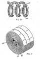
- Valve assembly 100includes an end cap 102, a stabilizer plate 104, a seal member 110 and a seal housing 112. End cap 102, stabilizer plate 104 and seal housing 112 form the outer valve body of valve assembly 100, which houses the sealing and dilating component, i.e., seal member 110.
- End cap 102is generally cylindrically-shaped and includes a proximal end portion 103 defining a diameter which is less than the diameter of the remaining portion of the end cap and an inner peripheral ledge 114 which supports stabilizer plate 104.
- Seal housing 112includes central opening 116, a proximal cylindrical portion 118 and a distal outer flange 120 having a scalloped surface to facilitate handling thereof. Cylindrical portion 118 is received within end cap 102 when the valve assembly 100 is fully assembled to enclose the sealing components.
- the distal end face of seal housing 112includes a peripheral groove 122 and two opposed rib portions 124 extending radially inwardly adjacent the groove 122.
- seal housing 112also includes a second groove 126 adjacent opening 116 for accommodating a portion of seal 110.
- sealing member 110is cylindrical having an outer cylindrical surface 127 and an inner cylindrical surface 128.
- Bristle members 132are preferably fabricated from an elastomeric material such as synthetic or natural rubber which is preferably sufficiently resilient to accommodate and provide a substantial seal with instruments of varying diameters inserted through aperture 134, e.g., instruments ranging in diameter from about 4.5mm to about 13mm, and sufficiently resilient to flex to accommodate manipulation of instrumentation inserted through aperture 134.
- valve assembly 100is shown already mounted to cannula assembly 200, it is to be appreciated that generally valve assembly 100 is first assembled as a single unit and then mounted to the cannula assembly 200. The mounting of valve assembly 100 to cannula assembly 200 will be discussed below.
- Stabilizer plate 104is positioned within end cap 102 such that the plate 104 rests on inner peripheral ledge 114 defined within the end cap 102.
- seal member 110is positioned over stabilizer plate 104.
- Seal housing 112is positioned over the entire unit with the cylindrical wall 118 of the seal housing 112 being received within the cylindrical wall of end cap 102.
- cannula assembly 200includes a cannula sleeve 202 and a cannula housing 204 mounted on one end of the sleeve 202.
- Cannula sleeve 202defines a cannula passage in its interior and may be formed of stainless steel or other suitable rigid materials such as polycarbonate materials or the like.
- Cannula housing 204is rigidly secured to the proximal end of cannula sleeve 202 and defines a longitudinal opening for reception and passage of an elongated surgical instrument.
- the proximal end portion of the cannula housing 204defines a generally circular cross-section and possesses diametrically opposed leg portions 206.
- Seal 208includes a circumferential flange portion 210 which rests on a correspondingly dimensioned circumferential ledge 212 within cannula housing 204.
- Seal 208generally defines a duck bill shape having two planar tapering portions 214 which intersect at their distal ends to define abutment face 216.
- the planar tapering portions 214may each include one or more inwardly directed, longitudinally oriented ribs to facilitate instrument passage.
- Abutment face 216permits passage of the elongated object through the seal 208, but in the absence of an instrument, and particularly when cannula sleeve 202 is inserted into an insufflated body cavity, abutment face 216 forms a tight seal that isolates the insufflated cavity from the ambient surroundings.
- Seal 208also includes at least one, preferably two, reinforcing ribs 215 to stabilize the seal. Ribs 215 are positioned to engage the instrument to guide the instrument through slits 216 and prevent piercing of the seal 208 by the tip of the instrument.
- Cannula assembly 200also includes a stabilizing plate 218 (FIG. 1) which is positioned against the flange portion 210 of seal 208 to provide support for seal 208 during introduction and withdrawal of an elongated instrument.
- Stabilizing plate 218includes two diametrically opposed extensions 220 (FIG. 1) which are received within the correspondingly dimensioned leg portions 206 of the cannula housing 204.
- stabilizing plate 218is securely attached to the cannula housing 204 at contact points along the extensions of the respective components by spot welding, adhesives or the like.
- Stabilizing plate 218also includes a partial external annular rib or thread 222 (FIG. 6) adjacent its proximal end, the function of which will be appreciated from the description below.
- a stop cock valve 224may be incorporated as part of cannula housing 204 to permit the passage of insufflation gases through the cannula and into the body cavity.
- a suitable valve for this purposeis available from the Burron OEM Division of B. Braun Medical, Inc. (Model No. 55401022).
- valve assembly 100is detachably mounted adjacent stabilizing plate 218 with the partial annular thread 222 of the stabilizing plate 218 being received within the peripheral groove 122 (FIG. 2) defined in the distal face of seal housing 112.
- the valve assembly 100is rotated to cause engagement of the radially inwardly projecting rib portions 124 adjacent groove 122 with the partial annular thread 222 to releasably lock the valve assembly 200 to the cannula housing 204.
- Other means for detachably connecting the valve assembly 100 to cannula housing 204can be readily determined by one skilled in the art such as screw threads, adhesives, bayonet locking, and the like.
- FIGS. 6A and 6BA first and second alternative embodiments for the valve assembly 100 are shown by FIGS. 6A and 6B, respectively.
- FIG. 6Ashows a valve assembly designated generally by reference numeral 600.
- FIG. 6Bshows a valve assembly designated generally by reference numeral 700.
- Valve assembly 600is preferably detachably mountable to the proximal end of cannula assembly 602.
- the surgeoncan remove the valve assembly 600 from the cannula assembly 602 at any time during the surgical procedure and, similarly, mount the valve assembly 600 to the cannula when desired.
- the valve assembly 600may be readily adapted for mounting to conventional cannulas of differing structures. The detachability of the valve assembly 600 from the cannula assembly 602 facilitates specimen removal through the cannula assembly 602.
- the valve assembly 600includes a housing which is formed by the snap fitting together of end cap 604 and lower housing member 606.
- the housing components of the valve assembly 600are formed of a polycarbonate material such as ABS available from the General Electric Company.
- a seal member 608is disposed within the valve assembly housing.
- the seal member 608is constructed from bristle members 610 connected to substrates 612 and 614 on opposite sides.
- the seal member 608includes a taper 616 to facilitate the insertion of a surgical instrument.
- the taper 616can have an angle less than 90 degrees with respect to the central longitudinal axis of the valve assembly 600. Bristle members 610 sealingly engage to form a seal about the surgical instrument when inserted within valve assembly 600 and a seal within the valve housing and the external atmosphere.
- a seal clamp 618is provided within the housing components 604 and 606 which secures O-ring 620 and lower seal 622 with respect to the valve assembly 600.
- Lower seal 622is provided at the distal end of lower housing member 606 and assists in the sealing engagement of valve assembly 600 to cannula assembly 602.
- the valve assembly 700is preferably detachably mountable to the proximal end of cannula assembly 702.
- the surgeoncan remove the valve assembly 700 from the cannula assembly 702 at any time during the surgical procedure and, similarly, mount the valve assembly 700 to the cannula when desired in order to provide a sealing engagement with an instrument to be inserted through the cannula.
- valve assembly 700may be readily adapted for mounting to conventional cannulas of differing structures.
- the detachability of the valve assembly 700 from the cannula assembly 702facilitates specimen removal through cannula assembly 702.
- the valve assembly 700includes a housing which is formed by the snap fitting together of end cap 704 and lower housing member 706.
- the housing components of valve assembly 700are formed of a polycarbonate material such as ABS available from the General Electric Company.
- a seal member 708is disposed within the valve assembly housing. Similarly to seal member 608, seal member 708 is constructed from bristle members 710 connected to substrates 712 and 714 on opposite sides.
- the seal member 708includes a taper 716 facilitate the insertion of the surgical instrument.
- the taper 716can have an angle less than 90 degrees with respect to the central longitudinal axis of the valve assembly 700.
- Bristle members 710sealingly engage to form a seal about the surgical instrument when inserted within valve assembly 700 and a seal within the valve housing and the external atmosphere.
- a seal clamp 718is provided within the housing components 704 and 706. Seal clamp 718 is further described in the PCT-application WO-A-9 850 093.
- a lower seal 720is provided at the distal end of lower housing member 706 and assists in the sealing engagement of valve assembly 700 to cannula assembly 702.
- an elongated objectsuch as a surgical instrument, identified generally by reference numeral 400
- a surgical instrumentidentified generally by reference numeral 400
- the tip of the surgical instrument 400is engaged by the bristle members 132.
- the bristle members 132are pivoted downwardly to increase the dimension of the aperture 134 to the degree necessary to accommodate instrument 400.
- the dimensions of the bristle members 132 and their flexibilitypermits relatively easy passage of instrument 400 through the valve assembly 100.
- the resilient seal member 110sealingly engages to form a seal about the surgical instrument and a seal within the valve housing and the external atmosphere.
- Instrument 400is advanced through cannula assembly 200 whereby the duckbill seal 208 of the cannula 200 also spreads to allow passage of instrument 400. Once positioned within the valve assembly 100 and cannula assembly 200, surgical instrument 400 may be maneuvered about the internal body cavity.
- the valve assembly 100permits limited unencumbered movement of instrument 400 in a radial direction (relative to the centerline of cannula sleeve 202) while still maintaining an adequate seal about the instrument.
- manipulation of the instrument 400 in any direction, either longitudinally or radially, to the extent permitted by the rigid housings and cannula sleeve 202,will not effect the integrity of the seal, since the resilient material of sealing member 110 will conform to the movements of the instrument and assume a shape necessary to retain a sealing contact with the instrument.
- FIG. 9also shows that the seal member 110 can maintain an adequate seal about an instrument having a diameter that is greater than the diameter of the instrument shown in FIG. 8.
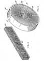
- FIGS. 10-13two alternative embodiments are shown for creating a seal using bristle members 132 connected to substrate 130.
- FIG. 10shows the substrate 130 having a spiral arrangement and
- FIG. 11shows the spiral arrangement of FIG. 10 in assembled form.
- FIG. 12shows a resilient sealing structure having four individual parts 138 and
- FIG. 13shows the resilient sealing structure shown in FIG. 12 arranged in a multi-array assembly.
Landscapes
- Health & Medical Sciences (AREA)
- Surgery (AREA)
- Life Sciences & Earth Sciences (AREA)
- Animal Behavior & Ethology (AREA)
- Public Health (AREA)
- Engineering & Computer Science (AREA)
- Biomedical Technology (AREA)
- Heart & Thoracic Surgery (AREA)
- Medical Informatics (AREA)
- Molecular Biology (AREA)
- Pathology (AREA)
- General Health & Medical Sciences (AREA)
- Nuclear Medicine, Radiotherapy & Molecular Imaging (AREA)
- Veterinary Medicine (AREA)
- Surgical Instruments (AREA)
- Media Introduction/Drainage Providing Device (AREA)
- Check Valves (AREA)
- External Artificial Organs (AREA)
- Infusion, Injection, And Reservoir Apparatuses (AREA)
- Endoscopes (AREA)
Description
- The present disclosure relates to apparatus that includes valve assemblies of the type adapted to allow the introduction of a surgical instrument into a patient's body. In particular, the disclosure relates to a valve assembly to be used in combination with a cannula assembly where the cannula assembly is intended for insertion into a patient's body and an instrument is inserted into the patient's body through the cannula.
- Laparoscopic procedures are performed in the interior of the abdomen through a small incision, e.g., through narrow endoscopic tubes or cannulas inserted through a small entrance incision in the skin. Minimally invasive procedures are performed elsewhere in the body, e.g., in the chest, and are often generally referred to as "endoscopic" procedures. Minimally invasive or endoscopic procedures generally require that any instrumentation inserted into the body be sealed, i.e. provisions must be made to ensure that gases do not enter or exit the body through the endoscopic incision as, for example, in surgical procedures in which the surgical region is insufflated. Moreover, endoscopic procedures often require the surgeon to act on organs, tissues, and vessels far removed from the incision, thereby requiring that any instruments used in such procedures be relatively long and narrow.
- For such procedures, the introduction of a tube into certain anatomical cavities such as the abdominal cavity is usually accomplished by use of a system incorporating a trocar and cannula assembly. A cannula assembly is formed of a cannula attached to a cannula housing which generally includes valve assembly adapted to maintain a seal across the opening of the valve assembly both with and without an instrument inserted therethrough. Since the cannula is in direct communication with the internal portion of the valve assembly, insertion of the cannula into an opening in the patient's body so as to reach the inner abdominal cavity should be adapted to maintain a tight interface between the abdominal cavity and the outside atmosphere.
- Since minimally invasive surgical procedures in the abdominal cavity of the body generally require insufflating gases to raise the cavity wall away from vital organs, the procedure is usually initiated by use of a Verres needle through which a gas is introduced into the body cavity. The gas provides a slight pressure which raises the wall surface of the peritoneum away from the vital organs thereby providing an adequate region in which to operate. Thereafter, a trocar assembly which includes a cannula and a trocar or obturator is inserted within the cannula to puncture the peritoneum, i.e. the inner lining of the abdominal cavity wall. The obturator is removed and laparoscopic or endoscopic surgical instruments may then be inserted through the cannula to perform surgery within the abdominal cavity. The cannula may also be utilized for introducing tubes into the body as for drainage purposes, for specimen removal, for diagnostic evaluations, or the like.
- In view of the need to maintain the atmospheric integrity of the inner area of the cavity, a valve assembly for a cannula which permits introduction of an obturator and a wide range of surgical instruments and which maintains the atmospheric integrity of the inner area of the cavity is desirable. Generally, in the context of insufflatory, minimally invasive surgical procedures, cannula assemblies include structure(s) that satisfy two sealing requirements. The first requirement is to provide a tight seal when an instrument is not present in the cannula. The second requirement is to provide a tight seal when an instrument is being introduced into or already is present in the cannula. In this regard, there have been a number of attempts in the prior art to provide such sealing requirements.
- A disadvantage of several known valve assemblies for cannulas, however, concerns the difficulty encountered in inserting and advancing the surgical instrument through the valve unit. In particular, since known elastomeric seal members are designed to form and maintain a tight seal about the instrument, the aperture or slit within the seal through which the instrument is passed is of relatively small or narrow dimension. Further, portions of the valve member defining the aperture are generally thick in cross-section to provide a sufficient closing force of the seal about the instrument. As a consequence of some of these design considerations, the level of force needed to insert and advance the instrument through the seal aperture is increased, thereby requiring awkward maneuvering on the surgeon's behalf to appropriately position the instrument for the desired surgery. Moreover, some known valve assemblies are generally ineffectual in accommodating instruments of differing diameter while maintaining acceptable insertion forces and facilitating the range of desired surgical manipulations, e.g., angular instrument movements and specimen removal.
- Accordingly, a need exists for an improved valve unit or cannula assembly which is capable of forming and maintaining a seal about instruments of varying diameters inserted through -the cannula and which incorporates structure to enhance and facilitate passage of the instrument through the valve unit.
- US-A-5 743 884 discloses a sealing structure for a medical instrument in which fingers project inwardly from an annular sealing ring, past the axis of the ring, to overlap at their distal tips to close the channel within the annulus along which the instrument is advanced.
US-A-5 997 515 discloses a trocar stabilizer seal with an annular membrane which is inflatable. The membrane comprises a plurality of bristle-like brush members extending inwardly from the balloon membrane to form a tortuous path type seal when the balloon membrane is inflated.
EP-A-0 696 459 discloses in combination the technical features of the preamble of theindependent claim 1 below. - The present invention defined below in
claim 1 obviates the disadvantages of the prior art by providing apparatus with a valve unit or assembly for a cannula assembly. Generally stated, the present disclosure is directed to cannula apparatus including a valve assembly for sealed reception of an elongated object. The assembly includes a valve body defining at least one opening configured and dimensioned to permit entry of an elongated object namely a surgical instrument and defining a central longitudinal axis, and an elongated seal member having a resilient sealing structure and defining an aperture in general alignment with the opening of the valve body whereby the aperture is configured and dimensioned such that upon insertion of the object into the aperture, the resilient sealing structure resiliently engages the outer surface of the object in a tight manner. The sealing structure includes a plurality of elongated bristle members attached to the seal member. The bristle members are positioned to engage the elongated object upon at least partial insertion of the elongated object into the valve body. Each bristle member is adapted to be displaced relative to the longitudinal axis to facilitate expansion of the aperture of the seal member upon entry of the elongated object therein. - The valve assembly includes a valve body defining a longitudinal opening configured and dimensioned to permit entry of an elongated object, an elongated resilient seal member at least partially positioned within the valve body and defining an aperture to permit entry of the elongated object therein in a tight manner and a plurality of bristle members attached to the seal member and concentrically arranged about the central longitudinal axis of the valve body. The plurality of bristle members are positioned to engage the elongated object upon insertion of the elongated object within the valve body and are adapted to be displaced upon introduction of the elongated object to engage portions of the seal member defining the aperture to expand the aperture.
- The bristle members of this embodiment are preferably linearly mounted on a substrate and extend generally perpendicularly with respect to the inner surface of the seal member. Upon entry of the elongated object, the bristle members simultaneously pivot downwardly to uniformly open or expand the aperture.
- The valve assembly is used in combination with a cannula including a cannula housing and a cannula sleeve extending distally from the cannula housing and is preferably detachably connected to the cannula housing. The cannula housing includes a valve member disposed therein which is moveable between a substantially closed position in the absence of an instrument to an open position in the presence of an instrument.
- Various embodiments are described hereinbelow with reference to the drawings wherein:
- FIG. 1 is a perspective view with parts separated of a trocar assembly, cannula assembly and valve assembly constructed according to the principles of the present disclosure;
- FIG. 2 is an enlarged perspective view with parts separated of the valve assembly of FIG. 1;
- FIG. 3 is an enlarged perspective view of the resilient sealing structure of the valve assembly of FIG. 2;
- FIG. 4 is an enlarged perspective view of the seal member shown in FIG. 2;
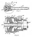
- FIG. 5 is a side plan view in partial cross-section of the cannula housing and the valve assembly detachably mounted to the cannula housing;
- FIG. 6 is an enlarged, partial cross-sectional view of the area of detail as indicated in FIG. 5, illustrating the valve assembly and the cannula housing;
- FIG. 6A is an enlarged, cross-sectional view of a first alternative valve assembly;
- FIG. 6B is an enlarged, cross-sectional view of a second alternative valve assembly;
- FIG. 7 is a view similar to FIG. 5 illustrating the introduction of an elongated object into the valve assembly and cannula assembly;
- FIG. 8 is a view similar to FIG. 6 of the area of detail as indicated in FIG. 7, illustrating sealing engagement of a resilient sealing structure of the valve assembly with an elongated object;
- FIG. 9 is a view similar to FIG. 8, illustrating the adaptability of the valve assembly to radial movement of an elongated object in the cannula assembly;
- FIG. 10 is an enlarged perspective view of a resilient sealing structure having a spiral arrangement;
- FIG. 11 is an enlarged perspective view of the resilient sealing structure of FIG. 10 in assembled form;
- FIG. 12 is an enlarged perspective view of a further alternative embodiment of a resilient sealing structure having four individual parts; and
- FIG. 13 is an enlarged perspective view of the resilient sealing structure of FIG. 12 where the four individual parts have been brought together to form a multi-array arrangement.
- The present disclosure contemplates the introduction into a person's body of all types of surgical instruments including clip appliers, graspers, dissectors, retractors, staplers, laser fibers, photographic devices, endoscopes and laparoscopes, tubes, and the like. All such objects are referred to herein as "instruments".
- Referring initially to FIG. 1, there is illustrated a
novel valve assembly 100 constructed in accordance with the principles of the present disclosure and intended to be used in combination with a conventional trocar assembly which generally includes acannula assembly 200 and atrocar assembly 300. - The
valve assembly 100 of the present disclosure, either alone or in combination with a valve unit/seal assembly internal tocannula assembly 200, and either integral with or detachably mounted tocannula assembly 200, provides a substantial seal between a body cavity of a patient and the outside atmosphere, both during and subsequent to insertion of an instrument through the cannula. Moreover, thevalve assembly 100 of the present disclosure is capable of accommodating instruments of varying diameter, e.g. from 4.5mm to 13mm, by providing a substantial seal with each instrument when inserted. Thevalve assembly 100 is designed with a predetermined leak rate not to exceed 266.6 N/m (2mm of mercury) in 20 seconds when theassembly 100 is manipulated by instruments of varying diameters, e.g., from about 4.5mm to about 13mm. The flexibility of the present valve assembly greatly facilitates endoscopic surgery where a variety of instruments having differing diameters are often needed during a single surgical procedure. - The
valve assembly 100 is preferably detachably mountable to the proximal end ofcannula assembly 200 disclosed herein. Thus, the surgeon can remove thevalve assembly 100 from thecannula assembly 200 at any time during the surgical procedure and, similarly, mount thevalve assembly 100 to the cannula when desired to provide a sealing engagement with an instrument to be inserted through the cannula. In addition, thevalve assembly 100 may be readily adapted to be mounted to conventional cannulas of differing structures. The detachability of thevalve assembly 100 fromcannula assembly 200 facilitates specimen removal throughcannula assembly 200 and reduces the profile ofcannula assembly 200 whenvalve assembly 100 is not needed for the surgical procedure. - Referring now to FIG. 2, the
novel valve assembly 100 of the present disclosure will be described in detail.Valve assembly 100 includes anend cap 102, astabilizer plate 104, aseal member 110 and a seal housing 112.End cap 102,stabilizer plate 104 and seal housing 112 form the outer valve body ofvalve assembly 100, which houses the sealing and dilating component, i.e.,seal member 110. End cap 102 is generally cylindrically-shaped and includes aproximal end portion 103 defining a diameter which is less than the diameter of the remaining portion of the end cap and an innerperipheral ledge 114 which supportsstabilizer plate 104. Seal housing 112 includescentral opening 116, a proximalcylindrical portion 118 and a distalouter flange 120 having a scalloped surface to facilitate handling thereof.Cylindrical portion 118 is received withinend cap 102 when thevalve assembly 100 is fully assembled to enclose the sealing components. The distal end face of seal housing 112 includes aperipheral groove 122 and twoopposed rib portions 124 extending radially inwardly adjacent thegroove 122. Groove 122 andrib portions 124 assist in mountingvalve assembly 100 tocannula assembly 200 as will be appreciated from the description provided below. The distal end face of seal housing 112 also includes asecond groove 126adjacent opening 116 for accommodating a portion ofseal 110.- Referring now to FIGS. 2-4, sealing
member 110 is cylindrical having an outercylindrical surface 127 and an innercylindrical surface 128. Asubstrate 130 having a plurality ofbristle members 132 attached thereto, as shown by FIG. 3, lines the innercylindrical surface 128 of the sealingmember 110 definingaperture 134.Bristle members 132 are preferably fabricated from an elastomeric material such as synthetic or natural rubber which is preferably sufficiently resilient to accommodate and provide a substantial seal with instruments of varying diameters inserted throughaperture 134, e.g., instruments ranging in diameter from about 4.5mm to about 13mm, and sufficiently resilient to flex to accommodate manipulation of instrumentation inserted throughaperture 134. - Referring now to FIG. 2 in conjunction with FIGS. 5 and 6, the assembling of the components of
valve assembly 100 will be described in detail. Although in FIGS. 5 and 6 thevalve assembly 100 is shown already mounted tocannula assembly 200, it is to be appreciated that generallyvalve assembly 100 is first assembled as a single unit and then mounted to thecannula assembly 200. The mounting ofvalve assembly 100 tocannula assembly 200 will be discussed below.Stabilizer plate 104 is positioned withinend cap 102 such that theplate 104 rests on innerperipheral ledge 114 defined within theend cap 102. Thereafter,seal member 110 is positioned overstabilizer plate 104. Seal housing 112 is positioned over the entire unit with thecylindrical wall 118 of the seal housing 112 being received within the cylindrical wall ofend cap 102. In this assembled condition, the distal end portion of the cylindrical wall ofend cap 102 is received within an annular space defined betweendistal flange 120 of seal housing 112 andcylindrical wall 118 of seal housing 112 and retained therein by, e.g., friction or snap fit, thus retaining thevalve assembly 100 in a fully assembled condition. - The
valve assembly 100 now in its fully assembled condition can be mounted tocannula assembly 200. Referring to FIGS. 1, 5 and 6,cannula assembly 200 includes acannula sleeve 202 and acannula housing 204 mounted on one end of thesleeve 202.Cannula sleeve 202 defines a cannula passage in its interior and may be formed of stainless steel or other suitable rigid materials such as polycarbonate materials or the like. Cannula housing 204 is rigidly secured to the proximal end ofcannula sleeve 202 and defines a longitudinal opening for reception and passage of an elongated surgical instrument. The proximal end portion of thecannula housing 204 defines a generally circular cross-section and possesses diametrically opposed leg portions 206. Acannula seal 208 fabricated from a resilient material, e.g., rubber, is positioned within the interior ofcannula housing 204.Seal 208 includes acircumferential flange portion 210 which rests on a correspondingly dimensionedcircumferential ledge 212 withincannula housing 204.Seal 208 generally defines a duck bill shape having twoplanar tapering portions 214 which intersect at their distal ends to defineabutment face 216. Theplanar tapering portions 214 may each include one or more inwardly directed, longitudinally oriented ribs to facilitate instrument passage.Abutment face 216 permits passage of the elongated object through theseal 208, but in the absence of an instrument, and particularly whencannula sleeve 202 is inserted into an insufflated body cavity,abutment face 216 forms a tight seal that isolates the insufflated cavity from the ambient surroundings.Seal 208 also includes at least one, preferably two, reinforcingribs 215 to stabilize the seal.Ribs 215 are positioned to engage the instrument to guide the instrument throughslits 216 and prevent piercing of theseal 208 by the tip of the instrument.Cannula assembly 200 also includes a stabilizing plate 218 (FIG. 1) which is positioned against theflange portion 210 ofseal 208 to provide support forseal 208 during introduction and withdrawal of an elongated instrument. Stabilizing plate 218 includes two diametrically opposed extensions 220 (FIG. 1) which are received within the correspondingly dimensioned leg portions 206 of thecannula housing 204. In the preferred embodiment, stabilizing plate 218 is securely attached to thecannula housing 204 at contact points along the extensions of the respective components by spot welding, adhesives or the like. Stabilizing plate 218 also includes a partial external annular rib or thread 222 (FIG. 6) adjacent its proximal end, the function of which will be appreciated from the description below.- A
stop cock valve 224 may be incorporated as part ofcannula housing 204 to permit the passage of insufflation gases through the cannula and into the body cavity. A suitable valve for this purpose is available from the Burron OEM Division of B. Braun Medical, Inc. (Model No. 55401022). - Referring still to FIGS. 1, 5 and 6, assembled
valve assembly 100 is detachably mounted adjacent stabilizing plate 218 with the partial annular thread 222 of the stabilizing plate 218 being received within the peripheral groove 122 (FIG. 2) defined in the distal face of seal housing 112. Thevalve assembly 100 is rotated to cause engagement of the radially inwardly projectingrib portions 124adjacent groove 122 with the partial annular thread 222 to releasably lock thevalve assembly 200 to thecannula housing 204. Other means for detachably connecting thevalve assembly 100 tocannula housing 204 can be readily determined by one skilled in the art such as screw threads, adhesives, bayonet locking, and the like. - A first and second alternative embodiments for the
valve assembly 100 are shown by FIGS. 6A and 6B, respectively. FIG. 6A shows a valve assembly designated generally byreference numeral 600. FIG. 6B shows a valve assembly designated generally byreference numeral 700.Valve assembly 600 is preferably detachably mountable to the proximal end of cannula assembly 602. Thus, the surgeon can remove thevalve assembly 600 from the cannula assembly 602 at any time during the surgical procedure and, similarly, mount thevalve assembly 600 to the cannula when desired. In addition, thevalve assembly 600 may be readily adapted for mounting to conventional cannulas of differing structures. The detachability of thevalve assembly 600 from the cannula assembly 602 facilitates specimen removal through the cannula assembly 602. - The
valve assembly 600 includes a housing which is formed by the snap fitting together ofend cap 604 and lower housing member 606. Preferably, the housing components of thevalve assembly 600 are formed of a polycarbonate material such as ABS available from the General Electric Company. Aseal member 608 is disposed within the valve assembly housing. Theseal member 608 is constructed from bristle members 610 connected tosubstrates seal member 608 includes a taper 616 to facilitate the insertion of a surgical instrument. The taper 616 can have an angle less than 90 degrees with respect to the central longitudinal axis of thevalve assembly 600. Bristle members 610 sealingly engage to form a seal about the surgical instrument when inserted withinvalve assembly 600 and a seal within the valve housing and the external atmosphere. - A
seal clamp 618 is provided within thehousing components 604 and 606 which secures O-ring 620 andlower seal 622 with respect to thevalve assembly 600.Lower seal 622 is provided at the distal end of lower housing member 606 and assists in the sealing engagement ofvalve assembly 600 to cannula assembly 602. - The
valve assembly 700 is preferably detachably mountable to the proximal end ofcannula assembly 702. Thus, the surgeon can remove thevalve assembly 700 from thecannula assembly 702 at any time during the surgical procedure and, similarly, mount thevalve assembly 700 to the cannula when desired in order to provide a sealing engagement with an instrument to be inserted through the cannula. In addition,valve assembly 700 may be readily adapted for mounting to conventional cannulas of differing structures. The detachability of thevalve assembly 700 from thecannula assembly 702 facilitates specimen removal throughcannula assembly 702. Thevalve assembly 700 includes a housing which is formed by the snap fitting together ofend cap 704 andlower housing member 706. Preferably, the housing components ofvalve assembly 700 are formed of a polycarbonate material such as ABS available from the General Electric Company. - A
seal member 708 is disposed within the valve assembly housing. Similarly to sealmember 608,seal member 708 is constructed frombristle members 710 connected tosubstrates 712 and 714 on opposite sides. Theseal member 708 includes ataper 716 facilitate the insertion of the surgical instrument. Thetaper 716 can have an angle less than 90 degrees with respect to the central longitudinal axis of thevalve assembly 700.Bristle members 710 sealingly engage to form a seal about the surgical instrument when inserted withinvalve assembly 700 and a seal within the valve housing and the external atmosphere. - A
seal clamp 718 is provided within thehousing components Seal clamp 718 is further described in the PCT-application WO-A-9 850 093. Alower seal 720 is provided at the distal end oflower housing member 706 and assists in the sealing engagement ofvalve assembly 700 tocannula assembly 702. - Referring now to FIGS. 7 and 8, an elongated object such as a surgical instrument, identified generally by
reference numeral 400, may be inserted through thevalve assembly 100 and into thecannula assembly 200 to perform the desired surgical procedure. As thesurgical instrument 400 enters thevalve assembly 100, the tip of thesurgical instrument 400 is engaged by thebristle members 132. Upon further advancement of thesurgical instrument 400, thebristle members 132 are pivoted downwardly to increase the dimension of theaperture 134 to the degree necessary to accommodateinstrument 400. The dimensions of thebristle members 132 and their flexibility permits relatively easy passage ofinstrument 400 through thevalve assembly 100. Theresilient seal member 110 sealingly engages to form a seal about the surgical instrument and a seal within the valve housing and the external atmosphere.Instrument 400 is advanced throughcannula assembly 200 whereby theduckbill seal 208 of thecannula 200 also spreads to allow passage ofinstrument 400. Once positioned within thevalve assembly 100 andcannula assembly 200,surgical instrument 400 may be maneuvered about the internal body cavity. - As shown in FIG. 9, the
valve assembly 100 permits limited unencumbered movement ofinstrument 400 in a radial direction (relative to the centerline of cannula sleeve 202) while still maintaining an adequate seal about the instrument. Thus, manipulation of theinstrument 400 in any direction, either longitudinally or radially, to the extent permitted by the rigid housings andcannula sleeve 202, will not effect the integrity of the seal, since the resilient material of sealingmember 110 will conform to the movements of the instrument and assume a shape necessary to retain a sealing contact with the instrument. FIG. 9 also shows that theseal member 110 can maintain an adequate seal about an instrument having a diameter that is greater than the diameter of the instrument shown in FIG. 8. - With reference to FIGS. 10-13, two alternative embodiments are shown for creating a seal using bristle
members 132 connected tosubstrate 130. FIG. 10 shows thesubstrate 130 having a spiral arrangement and FIG. 11 shows the spiral arrangement of FIG. 10 in assembled form. FIG. 12 shows a resilient sealing structure having four individual parts 138 and FIG. 13 shows the resilient sealing structure shown in FIG. 12 arranged in a multi-array assembly.
Claims (13)
- An apparatus for the introduction of an elongated instrument into the body of a patient while maintaining a seal between internal body portions and the outside atmosphere, which comprises:a) a cannula assembly (200) including a cannula housing (204) and a cannula sleeve (202) extending distally from the cannula housing, the housing including a valve member (208) disposed therein which is movable by the advance of the instrument through the housing from a substantially closed position in the absence of the instrument to an open position in the presence of the instrument; andb) a valve assembly (100) mounted to the cannula assembly, the valve assembly including:i) a valve body (102, 104, 112) defining at least one opening (116) configured and dimensioned to permit entry of the instrument and defining a central longitudinal axis; andii) an elongated seal member (110) having a resilient sealing structure defining an aperture (134) in general alignment with the opening of the valve body, the aperture being configured and dimensioned such that insertion of the instrument into the aperture causes the resilient sealing structure defining the aperture to resiliently engage the outer surface of the instrument in a tight manner,
characterized in that:the sealing structure includes a plurality of bristle members (132) with their proximal ends attached to the seal member and concentrically arranged about the central longitudinal axis defined by the valve body and their distal ends defining the periphery of said aperture and thereby positioned to engage the instrument upon its insertion within the valve body, each bristle member distal end being adapted to be displaced upon contact with the instrument upon its engagement with the seal member thereby to expand the aperture. - The apparatus according to claim 1, wherein the valve body has a cylindrical shape and includes a proximal end portion (103) defining a diameter which is less than the diameter of the remaining portion of the valve body and an inner peripheral ledge (114).
- The apparatus according to claim 1 or 2, wherein the elongated seal member (110) rests upon a stabilizer plate (104) when the seal member is disposed within the valve body.
- The apparatus according to claim 1, 2 or 3 further comprising a seal housing (112) which includes a central opening (116), a proximal cylindrical portion (118), a distal end face, and a distal outer flange (120) having a scalloped surface to facilitate handling thereof.
- The apparatus according to claim 4, wherein the cylindrical portion (118) is received within the valve body when the valve assembly (100) is fully assembled.
- The apparatus according to claim 4 or 5, wherein the distal end face includes a peripheral groove (122) and two opposed rib portions (124) extending radially inwardly adjacent the groove for mounting the valve assembly to a cannula.
- The apparatus according to any one of the preceding claims, wherein the plurality of bristle members (132) include end portions disposed on a substrate (130).
- The apparatus according to claim 7, wherein the substrate (130) is disposed on the inner surface (128) of the seal member (110) such that the bristle members (132) are disposed radially from the longitudinal axis of the valve body.
- The apparatus according to claim 8, wherein the substrate (130) is spirally arranged on the inner surface of the seal member.
- The apparatus according to claim 4, wherein the seal housing (112) and the seal member (110) define therebetween a space to permit radial movement of the seal member within the seal housing.
- The apparatus according to any one of the preceding claims, wherein the plurality of bristle members (132) are arranged in a multi-array.
- The apparatus according to any one of the preceding claims, wherein the sealing structure provides a seal having a predetermined leak rate less than or equal to 2 mm of mercury in 20 seconds for instruments having a diameter in the range of about 4.5 mm to about 13 mm.
- The apparatus according to any one of the preceding claims, wherein the plurality of bristle members (610, 710) form a taper (616, 716) having an angle less than 90 degrees with respect to the central longitudinal axis of the valve body.
Applications Claiming Priority (2)
| Application Number | Priority Date | Filing Date | Title |
|---|---|---|---|
| US513603 | 1995-08-10 | ||
| US09/513,603US6595946B1 (en) | 2000-02-25 | 2000-02-25 | Valve assembly |
Publications (2)
| Publication Number | Publication Date |
|---|---|
| EP1127550A1 EP1127550A1 (en) | 2001-08-29 |
| EP1127550B1true EP1127550B1 (en) | 2006-02-01 |
Family
ID=24043937
Family Applications (1)
| Application Number | Title | Priority Date | Filing Date |
|---|---|---|---|
| EP01103633AExpired - LifetimeEP1127550B1 (en) | 2000-02-25 | 2001-02-22 | Apparatus for introducing an instrument into the body of a patient |
Country Status (7)
| Country | Link |
|---|---|
| US (5) | US6595946B1 (en) |
| EP (1) | EP1127550B1 (en) |
| JP (2) | JP4786814B2 (en) |
| AU (1) | AU780609B2 (en) |
| CA (1) | CA2337982C (en) |
| DE (1) | DE60116908T2 (en) |
| ES (1) | ES2253288T3 (en) |
Families Citing this family (118)
| Publication number | Priority date | Publication date | Assignee | Title |
|---|---|---|---|---|
| US7153319B1 (en) | 2000-01-26 | 2006-12-26 | Genico, Inc. | Trocar system having shielded trocar |
| DE20015388U1 (en)* | 2000-09-06 | 2001-03-15 | Storm, Gerald, Dr., 86159 Augsburg | Device for sealing and lubricating instruments guided in trocar sleeves |
| US7344519B2 (en)* | 2001-08-31 | 2008-03-18 | Conmed Corporation | Trocar system |
| WO2003043683A1 (en)* | 2001-11-13 | 2003-05-30 | Applied Medical Resources Corporation | Multi-seal trocar system |
| US8137317B2 (en)* | 2002-03-15 | 2012-03-20 | Oscor Inc. | Locking vascular introducer assembly with adjustable hemostatic seal |
| US7083626B2 (en) | 2002-10-04 | 2006-08-01 | Applied Medical Resources Corporation | Surgical access device with pendent valve |
| US7390317B2 (en)* | 2002-12-02 | 2008-06-24 | Applied Medical Resources Corporation | Universal access seal |
| US8147457B2 (en)* | 2003-03-21 | 2012-04-03 | Ethicon Endo-Surgery, Inc. | Conical trocar seal |
| DE20305093U1 (en)* | 2003-03-29 | 2003-09-11 | Heske, Norbert F., 82288 Kottgeisering | Coaxial cannula with sealing element |
| US8663170B2 (en) | 2003-05-29 | 2014-03-04 | Covidien Lp | Rotating valve assembly including multi-lumen spherical valve |
| US7165568B2 (en)* | 2003-05-29 | 2007-01-23 | Axial Technologies Limited | Rotating valve assembly |
| US20040267202A1 (en)* | 2003-06-26 | 2004-12-30 | Potter Daniel J. | Tearable hemostasis valve and splittable sheath |
| US20050165433A1 (en)* | 2004-01-23 | 2005-07-28 | Haberland Gary W. | Trocar having planar fixed septum seal and related methods |
| US7585288B2 (en)* | 2004-01-23 | 2009-09-08 | Genico, Inc. | Trocar and cannula assembly having conical valve and related methods |
| US20060047293A1 (en)* | 2004-01-23 | 2006-03-02 | Haberland Gary W | Trocar having planar fixed septum seal and related methods |
| US7842013B2 (en)* | 2004-01-23 | 2010-11-30 | Genico, Inc. | Trocar and cannula assembly having conical valve and related methods |
| USD537941S1 (en) | 2004-03-09 | 2007-03-06 | Genico, Inc. | Combination medical clamp and medical coupler |
| US20050203467A1 (en)* | 2004-03-15 | 2005-09-15 | O'heeron Peter T. | Trocar seal |
| US20050209607A1 (en) | 2004-03-22 | 2005-09-22 | John Lipchitz | Medical cannula assembly |
| USD545964S1 (en)* | 2004-07-09 | 2007-07-03 | Erblan Surgical, Inc. | Combined seal and valve assembly |
| JP4922164B2 (en)* | 2004-07-21 | 2012-04-25 | タイコ ヘルスケア グループ リミテッド パートナーシップ | Introducer assembly with pendant seal |
| US7608082B2 (en)* | 2005-01-06 | 2009-10-27 | Tyco Healthcare Group Lp | Surgical seal for use in a surgical access apparatus |
| USD538930S1 (en)* | 2005-01-28 | 2007-03-20 | Matsushita Electric Industrial Co., Ltd. | Puncture needle cartridge |
| US20060212062A1 (en)* | 2005-03-16 | 2006-09-21 | David Farascioni | Radially expandable access system including trocar seal |
| US20060243744A1 (en)* | 2005-04-28 | 2006-11-02 | Kessell Michael R | Flow switch |
| EP1933733A2 (en) | 2005-10-14 | 2008-06-25 | Applied Medical Resources Corporation | Surgical access port |
| US20080017676A1 (en)* | 2006-03-10 | 2008-01-24 | Kessell Michael R | Fluid switch with seal |
| US8579807B2 (en) | 2008-04-28 | 2013-11-12 | Ethicon Endo-Surgery, Inc. | Absorbing fluids in a surgical access device |
| US8690831B2 (en) | 2008-04-25 | 2014-04-08 | Ethicon Endo-Surgery, Inc. | Gas jet fluid removal in a trocar |
| US20070244426A1 (en)* | 2006-04-13 | 2007-10-18 | Applied Medical Resources Corporation | Duck bill septum combination |
| DE112006003933B4 (en)* | 2006-06-20 | 2017-11-09 | Avesto Tech Bv | Access port valve assembly and medical access port |
| US20090032533A1 (en)* | 2006-07-06 | 2009-02-05 | Axial Technologies Ltd. | Flow switch and container |
| US8932275B2 (en)* | 2006-07-07 | 2015-01-13 | Covidien Lp | Surgical seal assembly |
| ES2389736T3 (en)* | 2006-07-07 | 2012-10-31 | Tyco Healthcare Group Lp | Surgical seal set |
| US8100928B2 (en)* | 2006-08-10 | 2012-01-24 | Ethicon, Inc. | Morcellator with detachable handle |
| US20080068932A1 (en)* | 2006-09-14 | 2008-03-20 | Bennie Mosley | Wrist watch for monitoring diabetes |
| US20080171988A1 (en)* | 2007-01-17 | 2008-07-17 | Erblan Surgical, Inc. | Double-cone sphincter introducer assembly and integrated valve assembly |
| DE102007008751A1 (en)* | 2007-02-22 | 2008-08-28 | Wisap Gesellschaft für wissenschaftlichen Apparatebau mbH | Device for cutting out and removing cylinders of tissue from tissue, has cutting device with hollow-cylindrical base body and distal opening on distal end of base body, where cutting element is provided for surrounding distal opening |
| US7981086B2 (en)* | 2007-05-22 | 2011-07-19 | Tyco Healthcare Group Lp | Surgical access assembly with winepress seal |
| EP1997444B1 (en)* | 2007-05-22 | 2011-09-14 | Tyco Healthcare Group LP | Access assembly with whisker seal |
| JP5575375B2 (en) | 2007-05-22 | 2014-08-20 | コヴィディエン リミテッド パートナーシップ | Surgical portal device with variable adjustability |
| US8133174B2 (en)* | 2007-05-30 | 2012-03-13 | Tyco Healthcare Group Lp | Self constricting orifice seal |
| CA2632369A1 (en) | 2007-05-31 | 2008-11-30 | Tyco Healthcare Group Lp | Access apparatus with shallow zero closure valve |
| US8100929B2 (en) | 2007-06-29 | 2012-01-24 | Ethicon Endo-Surgery, Inc. | Duckbill seal with fluid drainage feature |
| US8109539B2 (en)* | 2007-07-17 | 2012-02-07 | Krohn Kenneth P | Variable joining device and method for its use |
| US7918826B2 (en) | 2007-09-14 | 2011-04-05 | Ethicon Endo-Surgery, Inc. | Trocar assembly |
| US20090105635A1 (en)* | 2007-10-17 | 2009-04-23 | Tyco Healthcare Group Lp | Access assembly with seal lubricant mechanism |
| US7976501B2 (en) | 2007-12-07 | 2011-07-12 | Ethicon Endo-Surgery, Inc. | Trocar seal with reduced contact area |
| US8343041B2 (en)* | 2008-05-19 | 2013-01-01 | Boston Scientific Scimed, Inc. | Integrated locking device with passive sealing |
| US8636686B2 (en) | 2008-04-28 | 2014-01-28 | Ethicon Endo-Surgery, Inc. | Surgical access device |
| US8568362B2 (en) | 2008-04-28 | 2013-10-29 | Ethicon Endo-Surgery, Inc. | Surgical access device with sorbents |
| US8870747B2 (en)* | 2008-04-28 | 2014-10-28 | Ethicon Endo-Surgery, Inc. | Scraping fluid removal in a surgical access device |
| USD700326S1 (en) | 2008-04-28 | 2014-02-25 | Ethicon Endo-Surgery, Inc. | Trocar housing |
| US11235111B2 (en) | 2008-04-28 | 2022-02-01 | Ethicon Llc | Surgical access device |
| US9358041B2 (en) | 2008-04-28 | 2016-06-07 | Ethicon Endo-Surgery, Llc | Wicking fluid management in a surgical access device |
| US8273060B2 (en) | 2008-04-28 | 2012-09-25 | Ethicon Endo-Surgery, Inc. | Fluid removal in a surgical access device |
| US20090270686A1 (en)* | 2008-04-29 | 2009-10-29 | Ethicon Endo-Surgery, Inc. | Methods and devices for maintaining visibility during surgical procedures |
| US7981092B2 (en) | 2008-05-08 | 2011-07-19 | Ethicon Endo-Surgery, Inc. | Vibratory trocar |
| US9028448B2 (en)* | 2008-06-19 | 2015-05-12 | Covidien Lp | Access seal with interstitial channels |
| US8012129B2 (en)* | 2008-06-25 | 2011-09-06 | Tyco Healthcare Group Lp | Surgical portal apparatus with waffle seal |
| US8025640B2 (en) | 2008-06-27 | 2011-09-27 | Tyco Healthcare Group Lp | Pressurized surgical valve |
| US7850667B2 (en)* | 2008-06-27 | 2010-12-14 | Tyco Healthcare Group Lp | Low profile instrument access device |
| US8845647B2 (en)* | 2008-07-01 | 2014-09-30 | Proxima Medical AB | Device for mixing and applying a paste, such as bone cement |
| US8740925B2 (en)* | 2008-10-10 | 2014-06-03 | Covidien Lp | Trocar assembly |
| WO2010056538A1 (en)* | 2008-10-29 | 2010-05-20 | Tim Maguire | An automated vessel puncture device using three-dimensional(3d) near infrared (nir) imaging and a robotically driven needle |
| US20100114033A1 (en)* | 2008-11-06 | 2010-05-06 | Tyco Healthcare Group Lp | Surgical access device |
| BRPI0917035A2 (en) | 2008-12-04 | 2019-09-24 | Pivot Medical Inc | "telescope access cannula, telescope shutter, system, method for providing an access corridor from a first off-site location to a second on-site location" |
| US20100234688A1 (en)* | 2009-03-10 | 2010-09-16 | Tyco Healthcare Group Lp | Access port including multi-layer seal and suture parks |
| US9138207B2 (en) | 2009-05-19 | 2015-09-22 | Teleflex Medical Incorporated | Methods and devices for laparoscopic surgery |
| US8430812B2 (en)* | 2009-10-05 | 2013-04-30 | Covidien Lp | Surgical access assembly |
| US8454563B2 (en) | 2009-10-09 | 2013-06-04 | Rogelio A. Insignares | Trocar and cannula assembly having improved conical valve, and methods related thereto |
| US8025641B2 (en)* | 2009-12-18 | 2011-09-27 | Tyco Healthcare Group Lp | Powered variable seal diameter trocar employing a winepress mechanism |
| USD676544S1 (en)* | 2009-12-22 | 2013-02-19 | Karl Storz Gmbh & Co. Kg | Suction pipe |
| US8721539B2 (en) | 2010-01-20 | 2014-05-13 | EON Surgical Ltd. | Rapid laparoscopy exchange system and method of use thereof |
| EP3251604B1 (en) | 2010-01-20 | 2020-04-22 | EON Surgical Ltd. | System of deploying an elongate unit in a body cavity |
| DE102010005950B4 (en)* | 2010-01-25 | 2013-02-28 | Daxten Ltd. | Device for passing one or more lines through an opening in a wall or a floor |
| US20110237900A1 (en)* | 2010-03-25 | 2011-09-29 | Tyco Healthcare Group Lp | Portal apparatus with a tubular seal device |
| US8956341B2 (en) | 2010-06-10 | 2015-02-17 | Carefusion 2200, Inc. | Surgical device with reusable handle |
| US8652104B2 (en) | 2010-06-25 | 2014-02-18 | Smiths Medical Asd, Inc. | Catheter assembly with seal member |
| US9545495B2 (en)* | 2010-06-25 | 2017-01-17 | Smiths Medical Asd, Inc. | Catheter assembly with seal member |
| EP2615980B1 (en) | 2010-09-19 | 2017-08-16 | EON Surgical Ltd. | Micro laparoscopy devices and deployments thereof |
| US8562520B2 (en) | 2010-10-01 | 2013-10-22 | Covidien Lp | Access port |
| US8821526B2 (en) | 2010-11-11 | 2014-09-02 | Specialtycare, Inc. | Trocar |
| US9101315B2 (en) | 2010-11-11 | 2015-08-11 | Specialty Care, Inc. | Cannula system |
| WO2013012790A2 (en)* | 2011-07-15 | 2013-01-24 | The Johns Hopkins University | Multi-purpose trocar with lens cleaner |
| US9320507B2 (en) | 2012-03-26 | 2016-04-26 | Covidien Lp | Cannula valve assembly |
| US9186173B2 (en) | 2012-04-27 | 2015-11-17 | Specialty Care, Inc. | Optical obturator system |
| WO2014022500A1 (en)* | 2012-07-31 | 2014-02-06 | The Charles Stark Draper Laboratory, Inc. | Implantable device for directional control of flow within the anatomic tracts of the body |
| USD724199S1 (en)* | 2012-08-30 | 2015-03-10 | Guided Therapeutics, Inc. | Medical diagnostic stand off tube |
| CA2879636C (en)* | 2012-09-28 | 2020-06-09 | Covidien Lp | Optical trocar visualization system and apparatus |
| US9089363B2 (en) | 2012-10-26 | 2015-07-28 | Arthrex, Inc. | Arthroscopic cannula dams for fluid control |
| US9498249B2 (en) | 2012-11-21 | 2016-11-22 | P Tech, Llc | Expandable access systems and methods |
| US10492825B2 (en) | 2013-03-15 | 2019-12-03 | Intuitive Surgical Operations, Inc. | Sealing multiple surgical instruments |
| US9888941B2 (en) | 2013-03-15 | 2018-02-13 | Intuitive Surgical Operations, Inc. | Sealing multiple surgical instruments |
| US10292730B2 (en) | 2013-03-15 | 2019-05-21 | Intuitive Surgical Operations, Inc. | Sealing multiple surgical instruments |
| US10070887B2 (en) | 2013-03-15 | 2018-09-11 | Intuitive Surgical Operations, Inc. | Sealing multiple surgical instruments |
| US9629681B2 (en) | 2013-03-15 | 2017-04-25 | Intuitive Surgical Operations, Inc. | Sealing multiple surgical instruments |
| CN105209106B (en)* | 2013-03-15 | 2020-03-20 | 直观外科手术操作公司 | Sealing multiple surgical instruments |
| US9021965B1 (en)* | 2013-04-16 | 2015-05-05 | Kontek Industries, Inc. | Laser defense gun ports |
| KR102708964B1 (en) | 2014-03-17 | 2024-09-25 | 인튜어티브 서지컬 오퍼레이션즈 인코포레이티드 | Cannula seal assembly |
| KR101642601B1 (en)* | 2014-11-28 | 2016-07-29 | (주)지 메디 | Trocar for laparoscope |
| US9796432B2 (en) | 2015-03-20 | 2017-10-24 | Carrier Corporation | Heat deflector for tractor-trailer refrigeration system |
| US10279649B2 (en) | 2015-03-20 | 2019-05-07 | Carrier Corporation | Heat and dust shield |
| US11510730B2 (en) | 2016-03-26 | 2022-11-29 | Paul Joseph Weber | Apparatus and methods for minimally invasive dissection and modification of tissues |
| US10893899B2 (en) | 2016-03-26 | 2021-01-19 | Paul Weber | Apparatus and systems for minimally invasive dissection of tissues |
| US10603101B2 (en) | 2016-03-26 | 2020-03-31 | Paul Joseph Weber | Apparatus, systems and methods for minimally invasive dissection of tissues |
| JP6871279B2 (en) | 2016-07-11 | 2021-05-12 | コンメッド コーポレーション | Cannula assembly for robot-assisted pressure-controlled laparoscopic surgery |
| US10090616B1 (en)* | 2017-06-27 | 2018-10-02 | Ethicon Llc | Surgical instrument handle assembly with feature to clean electrical contacts at modular shaft interface |
| WO2019033006A1 (en)* | 2017-08-11 | 2019-02-14 | Boston Scientific Scimed, Inc. | Biopsy cap for use with endoscope |
| US10463396B2 (en)* | 2017-10-23 | 2019-11-05 | Conmed Corporation | Devices for performing minimally invasive surgery having bellows support housing |
| US11326490B2 (en)* | 2018-05-02 | 2022-05-10 | Faurecia Emissions Control Technologies, Usa, Llc | Variable restriction valve for vehicle exhaust system |
| EP3817637B1 (en) | 2018-11-02 | 2023-10-25 | Boston Scientific Medical Device Limited | Devices for providing sealable access to a working channel |
| US11357542B2 (en) | 2019-06-21 | 2022-06-14 | Covidien Lp | Valve assembly and retainer for surgical access assembly |
| US11812991B2 (en) | 2019-10-18 | 2023-11-14 | Covidien Lp | Seal assemblies for surgical access assemblies |
| US11642153B2 (en) | 2020-03-19 | 2023-05-09 | Covidien Lp | Instrument seal for surgical access assembly |
| US11541218B2 (en) | 2020-03-20 | 2023-01-03 | Covidien Lp | Seal assembly for a surgical access assembly and method of manufacturing the same |
| US11446058B2 (en) | 2020-03-27 | 2022-09-20 | Covidien Lp | Fixture device for folding a seal member |
| US11717321B2 (en) | 2020-04-24 | 2023-08-08 | Covidien Lp | Access assembly with retention mechanism |
Family Cites Families (132)
| Publication number | Priority date | Publication date | Assignee | Title |
|---|---|---|---|---|
| GB148857A (en) | 1918-01-18 | 1921-06-23 | Mansfeld Sche Kupferschiefer B | Improvements in and relating to chill-moulds for the casting of metals and alloys |
| US3421509A (en) | 1965-12-17 | 1969-01-14 | John M Fiore | Urethral catheter |
| US3565078A (en) | 1969-04-25 | 1971-02-23 | Bard Inc C R | Quick disconnect catheter coupling |
| US3907310A (en) | 1971-02-25 | 1975-09-23 | Gas Dev Corp | Floating seal construction |
| US3853127A (en) | 1973-04-03 | 1974-12-10 | R Spademan | Elastic sealing member |
| US3994287A (en) | 1974-07-01 | 1976-11-30 | Centre De Recherche Industrielle Du Quebec | Trocar |
| GB1482857A (en) | 1974-09-10 | 1977-08-17 | Wolf Gmbh Richard | Trocar guides |
| US4000739A (en) | 1975-07-09 | 1977-01-04 | Cordis Corporation | Hemostasis cannula |
| US4112932A (en) | 1977-02-24 | 1978-09-12 | Chiulli Robert D | Laparoscopic cannula |
| JPS6034241Y2 (en) | 1977-04-25 | 1985-10-12 | オリンパス光学工業株式会社 | Endoscope passage sealing device |
| US4177814A (en) | 1978-01-18 | 1979-12-11 | KLI, Incorporated | Self-sealing cannula |
| DE2817102C2 (en) | 1978-04-19 | 1985-01-24 | Dr. Eduard Fresenius, Chemisch-pharmazeutische Industrie KG, 6380 Bad Homburg | Connector for plastic cannulas or venous catheters |
| US4202554A (en)* | 1978-05-17 | 1980-05-13 | Rolls-Royce Limited | Brush seals |
| US4173350A (en) | 1978-08-07 | 1979-11-06 | Roy E. Roth Company | Floating seals |
| US4177997A (en) | 1978-12-08 | 1979-12-11 | General Motors Corporation | Floating seal |
| US4298648A (en) | 1979-02-28 | 1981-11-03 | Celanese Corporation | Belting fabric |
| CA1136665A (en) | 1979-11-27 | 1982-11-30 | Ernst A. Kronenberg | Shaft seal of the type incorporating a sealing flange |
| US4240335A (en) | 1979-12-13 | 1980-12-23 | Honeywell Inc. | Floating seal for fluidic devices |
| US4386756A (en) | 1980-03-27 | 1983-06-07 | Valve Concepts International | Self centering floating metal seal for a ball valve |
| US4334688A (en) | 1980-05-08 | 1982-06-15 | The United States Of America As Represented By The Secretary Of The Navy | Fluid lubricated floating bushing seal |
| DE3042229C2 (en) | 1980-11-08 | 1983-10-27 | B. Braun Melsungen Ag, 3508 Melsungen | Insertion device for inserting elongated objects into blood vessels |
| US4338689A (en) | 1980-12-05 | 1982-07-13 | Kaiser Aerospace & Electronics Corporation | Self-aligning valve assembly |
| US4430081A (en) | 1981-01-06 | 1984-02-07 | Cook, Inc. | Hemostasis sheath |
| US4464178A (en) | 1981-11-25 | 1984-08-07 | Dalton Michael J | Method and apparatus for administration of fluids |
| US4468224A (en)* | 1982-01-28 | 1984-08-28 | Advanced Cardiovascular Systems, Inc. | System and method for catheter placement in blood vessels of a human patient |
| DE3217118C1 (en) | 1982-05-07 | 1983-08-25 | Busak + Luyken GmbH & Co, 7000 Stuttgart | Seal arrangement for shafts |
| US4447237A (en) | 1982-05-07 | 1984-05-08 | Dow Corning Corporation | Valving slit construction and cooperating assembly for penetrating the same |
| US5308336A (en) | 1982-09-28 | 1994-05-03 | Applied Medical Resources | Seal protection mechanism |
| EP0113520A2 (en) | 1982-12-06 | 1984-07-18 | Vance Products Incorporated | Nephroscopy cannula |
| US4601710B1 (en) | 1983-08-24 | 1998-05-05 | United States Surgical Corp | Trocar assembly |
| US4655752A (en) | 1983-10-24 | 1987-04-07 | Acufex Microsurgical, Inc. | Surgical cannula |
| US4653477A (en) | 1984-09-13 | 1987-03-31 | Olympus Optical Co., Ltd. | Endoscope forceps stopcock |
| US4553760A (en) | 1984-11-19 | 1985-11-19 | Caterpillar Tractor Co. | Flexible seal for a spherical joint |
| JPS61154679A (en) | 1984-12-28 | 1986-07-14 | テルモ株式会社 | Medical instrument |
| JPH0211655Y2 (en) | 1985-03-29 | 1990-03-27 | ||
| US4705511A (en) | 1985-05-13 | 1987-11-10 | Bipore, Inc. | Introducer sheath assembly |
| US4595207A (en)* | 1985-07-09 | 1986-06-17 | Mtu Motoren-Und Turbinen-Union Munchen Gmbh | Brush seal labyrinth sealing means between two machine parts |
| US4929235A (en) | 1985-07-31 | 1990-05-29 | Universal Medical Instrument Corp. | Self-sealing percutaneous tube introducer |
| US4626245A (en) | 1985-08-30 | 1986-12-02 | Cordis Corporation | Hemostatis valve comprising an elastomeric partition having opposed intersecting slits |
| GB8527646D0 (en) | 1985-11-08 | 1985-12-11 | Cox J A | Devices for sampling drainage |
| US4588195A (en) | 1985-11-22 | 1986-05-13 | Dana Corporation | Floating lip seal assembly with convoluted flexible section |
| US4654030A (en) | 1986-02-24 | 1987-03-31 | Endotherapeutics | Trocar |
| DE3616689C1 (en) | 1986-05-16 | 1987-11-19 | Mueller Heinz Konrad Prof Dr I | poetry |
| GB8618253D0 (en) | 1986-07-25 | 1986-09-03 | Wallace Ltd H G | Intermittent administration of therapeutic substance |
| US4779904A (en)* | 1986-10-31 | 1988-10-25 | Rich Christopher K | Couplings for connecting vehicle exhaust tail pipes to exhaust conduits for removing vehicle exhaust gases |
| US4723550A (en) | 1986-11-10 | 1988-02-09 | Cordis Corporation | Leakproof hemostasis valve with single valve member |
| DE3852463T2 (en) | 1987-10-13 | 1995-05-18 | United States Surgical Corp | Trocar cutlery. |
| US4909798A (en) | 1987-11-12 | 1990-03-20 | Daig Corporation | Universal hemostasis cannula |
| GB2212228B (en)* | 1987-11-13 | 1991-08-07 | Rolls Royce Plc | Enhanced performance brush seals |
| JPH0198368U (en) | 1987-12-23 | 1989-06-30 | ||
| US5053016A (en) | 1987-12-31 | 1991-10-01 | United States Surgical Corporation | Valve seat for an insufflation cannula assembly |
| US4943280A (en) | 1987-12-31 | 1990-07-24 | United States Surgical Corporaiton | Self-seating flapper valve for an insufflation cannula assembly |
| US4842591A (en) | 1988-01-21 | 1989-06-27 | Luther Ronald B | Connector with one-way septum valve, and assembly |
| US4857062A (en) | 1988-03-09 | 1989-08-15 | Medical Parameters, Inc. | Catheter introducer valve |
| DE3809127C1 (en) | 1988-03-18 | 1989-04-13 | B. Braun Melsungen Ag, 3508 Melsungen, De | |
| US4960412A (en) | 1988-04-15 | 1990-10-02 | Universal Medical Instrument Corp. | Catheter introducing system |
| US4869717A (en) | 1988-04-25 | 1989-09-26 | Adair Edwin Lloyd | Gas insufflation needle with instrument port |
| US4874378A (en) | 1988-06-01 | 1989-10-17 | Cordis Corporation | Catheter sheath introducer |
| US4844484A (en) | 1988-06-28 | 1989-07-04 | Dana Corporation | Floating lip seal with reinforced flexible portion |
| US4989919A (en)* | 1988-08-30 | 1991-02-05 | Pratt & Whitney Canada | Method and apparatus for manufacturing compliant brush seals |
| US5000745A (en) | 1988-11-18 | 1991-03-19 | Edward Weck Incorporated | Hemostatis valve |
| US4932633A (en) | 1988-11-21 | 1990-06-12 | Schneider-Shiley (U.S.A.) Inc. | Hemostasis valve |
| US5002557A (en) | 1989-04-06 | 1991-03-26 | Hasson Harrith M | Laparoscopic cannula |
| US5029875A (en)* | 1989-07-07 | 1991-07-09 | Textron Inc. | Fluid seal structure |
| US4998740A (en) | 1989-09-29 | 1991-03-12 | Rockwell International Corporation | Face seal assembly |
| US5104383A (en) | 1989-10-17 | 1992-04-14 | United States Surgical Corporation | Trocar adapter seal and method of use |
| US5038756A (en) | 1989-10-30 | 1991-08-13 | Storz Instrument Company | Needle interface boot for ultrasonic surgical instrument |
| US5127626A (en) | 1989-10-31 | 1992-07-07 | Applied Vascular Devices, Inc. | Apparatus for sealing around members extending therethrough |
| US5041095A (en) | 1989-12-22 | 1991-08-20 | Cordis Corporation | Hemostasis valve |
| US5053014A (en) | 1990-02-01 | 1991-10-01 | Critikon, Inc. | Catheter with controlled valve |
| US5015000A (en) | 1990-06-28 | 1991-05-14 | Moog Controls, Inc. | Floating seal arrangement |
| US5429609A (en) | 1990-07-26 | 1995-07-04 | Yoon; Inbae | Endoscopic portal for use in endoscopic procedures and methods therefor |
| US5395342A (en) | 1990-07-26 | 1995-03-07 | Yoon; Inbae | Endoscopic portal |
| GB9020317D0 (en)* | 1990-09-18 | 1990-10-31 | Cross Mfg Co | Sealing devices |
| US5073169A (en) | 1990-10-02 | 1991-12-17 | Steve Raiken | Trocar support |
| GB9103459D0 (en)* | 1991-02-19 | 1991-04-03 | Cross Mfg Co | Brush seal assembly |
| US5137520A (en) | 1991-04-24 | 1992-08-11 | Wayne Maxson | Cannula skirt |
| US5290304A (en) | 1991-05-14 | 1994-03-01 | Ingram S. Chodorow | Trocar system |
| US5180373A (en) | 1991-06-07 | 1993-01-19 | United States Surgical Corporation | Valve system for introducing objects into anatomical body portions |
| US5385553A (en) | 1991-07-18 | 1995-01-31 | Applied Medical Resources Corporation | Trocar with floating septum seal |
| EP0600895B1 (en) | 1991-08-30 | 1999-08-04 | Origin Medsystems, Inc. | Trocar with multiple converters and detachable obturator |
| US5197955A (en) | 1991-10-18 | 1993-03-30 | Ethicon, Inc. | Universal seal for trocar assembly |
| US5545142A (en) | 1991-10-18 | 1996-08-13 | Ethicon, Inc. | Seal members for surgical trocars |
| US5201530A (en)* | 1991-10-18 | 1993-04-13 | United Technologies Corporation | Multi-layered brush seal |
| US5209736A (en) | 1991-10-18 | 1993-05-11 | Ethicon, Inc. | Trocar method and apparatus |
| US5167636A (en) | 1991-10-24 | 1992-12-01 | Mectra Labs, Inc. | Cannula sealing mechanism |
| US5299813A (en) | 1991-12-20 | 1994-04-05 | Ingersoll-Dresser Pump Company | Floating seal ring |
| US5242412A (en) | 1992-01-21 | 1993-09-07 | Blake Joseph W Iii | Trocar tube subassembly having sealing ring and duckbill sealing tube having planar, truncate, diverging sealing bills |
| US5201714A (en) | 1992-03-05 | 1993-04-13 | Conmed Corporation | Laparoscopic cannula |
| US5221264A (en) | 1992-03-10 | 1993-06-22 | Wilk Peter J | Reduction port for laparoscopic trocar sleeve and related method |
| US5226891A (en) | 1992-04-07 | 1993-07-13 | Applied Medical Resources | Seal protection apparatus |
| FR2690493B1 (en)* | 1992-04-23 | 1996-10-25 | Snecma | BRUSHED ANNULAR JOINT. |
| US5443452A (en) | 1992-07-02 | 1995-08-22 | Applied Medical Resources | Seal assembly for access device |
| US5496280A (en) | 1992-07-02 | 1996-03-05 | Applied Medical Resources Corporation | Trocar valve assembly |
| US5400586A (en) | 1992-07-28 | 1995-03-28 | General Electric Co. | Self-accommodating brush seal for gas turbine combustor |
| US5568931A (en) | 1992-08-20 | 1996-10-29 | General Electric Company | Brush seal |
| US5474306A (en)* | 1992-11-19 | 1995-12-12 | General Electric Co. | Woven seal and hybrid cloth-brush seals for turbine applications |
| US5743884A (en) | 1992-12-17 | 1998-04-28 | Hasson; Harrith M. | Sealing structure for medical instrument |
| US5320611A (en) | 1993-02-04 | 1994-06-14 | Peter M. Bonutti | Expandable cannula having longitudinal wire and method of use |
| US5407433A (en) | 1993-02-10 | 1995-04-18 | Origin Medsystems, Inc. | Gas-tight seal accommodating surgical instruments with a wide range of diameters |
| US5411483A (en) | 1993-02-10 | 1995-05-02 | Origin Medsystems, Inc. | Gas-tight seal accommodating surgical instruments with a wide range of diameters |
| US5354280A (en) | 1993-02-19 | 1994-10-11 | Habley Medical Technology Corporation | Trocar and seal arrangement |
| US5554124A (en) | 1993-03-08 | 1996-09-10 | Alvarado; Alfredo | Universal gasket for laparoscopic cannula |
| US5380288A (en) | 1993-03-30 | 1995-01-10 | Innovasive Devices, Inc. | Surgical cannula and trocar system and method of using the same |
| US5391153A (en) | 1993-04-09 | 1995-02-21 | Habley Medical Technology Corporation | Trocar with linear movement seal |
| US5342315A (en) | 1993-04-12 | 1994-08-30 | Ethicon, Inc. | Trocar seal/protector assemblies |
| CA2126150C (en)* | 1993-07-14 | 2005-02-22 | David T. Green | Seal assembly for accommodating introduction of surgical instruments |
| US5485553A (en) | 1993-10-29 | 1996-01-16 | Hewlett-Packard Company | Method and apparatus for managing and initiating video capture and printing |
| US5445142A (en)* | 1994-03-15 | 1995-08-29 | Ethicon Endo-Surgery, Inc. | Surgical trocars having optical tips defining one or more viewing ports |
| US5542582A (en)* | 1994-07-22 | 1996-08-06 | Ligon; Robert M. | Dispensing system for particulate material |
| US5603702A (en)* | 1994-08-08 | 1997-02-18 | United States Surgical Corporation | Valve system for cannula assembly |
| US5439455A (en) | 1994-08-11 | 1995-08-08 | General Surgical Innovations, Inc. | Combination introducer cannula and reducer for use therein |
| US5752938A (en)* | 1994-09-12 | 1998-05-19 | Richard-Allan Medical Industries, Inc. | Seal for surgical instruments |
| US5643227A (en) | 1995-01-19 | 1997-07-01 | Stevens; Robert C. | Hemostasis cannula valve apparatus and method of using same |
| US5857999A (en) | 1995-05-05 | 1999-01-12 | Imagyn Medical Technologies, Inc. | Small diameter introducer for laparoscopic instruments |
| US5997515A (en)* | 1995-05-19 | 1999-12-07 | General Surgical Innovations, Inc. | Screw-type skin seal with inflatable membrane |
| US5584850A (en) | 1995-05-25 | 1996-12-17 | Applied Medical Resources Corporation | Trocar having an anti-inversion seal |
| US5643301A (en) | 1995-06-07 | 1997-07-01 | General Surgical Innovations, Inc. | Cannula assembly with squeeze operated valve |
| US5782817A (en) | 1995-11-06 | 1998-07-21 | Cordis Corporation | Catheter introducer having toroidal valve |
| US5628732A (en)* | 1996-01-19 | 1997-05-13 | Ethicon Endo-Surgery, Inc. | Trocar with improved universal seal |
| US5868714A (en)* | 1996-09-16 | 1999-02-09 | Endoscopic Concepts, Inc. | Trocar reducer system |
| DE19641375C1 (en)* | 1996-10-08 | 1997-12-04 | Mtu Muenchen Gmbh | Device for producing ring-shaped brush seals with inclined bristles |
| US6276661B1 (en) | 1996-11-06 | 2001-08-21 | Medtronic, Inc. | Pressure actuated introducer valve |
| US5792113A (en) | 1996-12-12 | 1998-08-11 | Ethicon Endo-Surgerym Inc. | Universal seal for a trocar |
| DE19712088C2 (en)* | 1997-03-22 | 1999-06-24 | Mtu Muenchen Gmbh | Brush seal with bristles inclined in the circumferential direction |
| EP2111884A1 (en) | 1997-05-28 | 2009-10-28 | United States Surgical Corporation | Trocar seal system |
| GB9801864D0 (en)* | 1998-01-30 | 1998-03-25 | Rolls Royce Plc | A seal arrangement |
| US6228061B1 (en)* | 1998-02-03 | 2001-05-08 | Imagyn Medical Technologies California, Inc. | Trocar seal system having dual seals |
| US5989224A (en) | 1998-02-23 | 1999-11-23 | Dexide Corporation | Universal seal for use with endoscopic cannula |
| JP4208266B2 (en)* | 1998-04-13 | 2009-01-14 | アプライド メディカル リソーシーズ コーポレイション | Conical universal seal with non-uniform surface and sealing device including the same |
| US6210064B1 (en)* | 1998-12-28 | 2001-04-03 | General Housewares Corp. | Soap-fillable brush with sealed actuator |
| US7241307B2 (en)* | 2001-12-31 | 2007-07-10 | Medcool, Inc. | Method and apparatus for managing temperature in a patient |
- 2000
- 2000-02-25USUS09/513,603patent/US6595946B1/ennot_activeExpired - Fee Related
- 2001
- 2001-02-22ESES01103633Tpatent/ES2253288T3/ennot_activeExpired - Lifetime
- 2001-02-22DEDE60116908Tpatent/DE60116908T2/ennot_activeExpired - Lifetime
- 2001-02-22EPEP01103633Apatent/EP1127550B1/ennot_activeExpired - Lifetime
- 2001-02-23CACA002337982Apatent/CA2337982C/ennot_activeExpired - Fee Related
- 2001-02-23AUAU23194/01Apatent/AU780609B2/ennot_activeCeased
- 2001-02-26JPJP2001103891Apatent/JP4786814B2/ennot_activeExpired - Fee Related
- 2003
- 2003-07-01USUS10/611,712patent/US6923783B2/ennot_activeExpired - Fee Related
- 2005
- 2005-03-21USUS11/085,303patent/US7559918B2/ennot_activeExpired - Fee Related
- 2009
- 2009-07-13USUS12/501,928patent/US7850655B2/ennot_activeExpired - Fee Related
- 2010
- 2010-08-10JPJP2010190058Apatent/JP2011005275A/enactivePending
- 2010-09-30USUS12/895,089patent/US8152774B2/ennot_activeExpired - Fee Related
Also Published As
| Publication number | Publication date |
|---|---|
| EP1127550A1 (en) | 2001-08-29 |
| US6595946B1 (en) | 2003-07-22 |
| CA2337982A1 (en) | 2001-08-25 |
| JP4786814B2 (en) | 2011-10-05 |
| US20090275880A1 (en) | 2009-11-05 |
| US8152774B2 (en) | 2012-04-10 |
| DE60116908T2 (en) | 2006-09-14 |
| AU2319401A (en) | 2001-08-30 |
| ES2253288T3 (en) | 2006-06-01 |
| DE60116908D1 (en) | 2006-04-13 |
| US7559918B2 (en) | 2009-07-14 |
| JP2011005275A (en) | 2011-01-13 |
| AU780609B2 (en) | 2005-04-07 |
| US20040092862A1 (en) | 2004-05-13 |
| US7850655B2 (en) | 2010-12-14 |
| JP2001314516A (en) | 2001-11-13 |
| US20110021977A1 (en) | 2011-01-27 |
| US6923783B2 (en) | 2005-08-02 |
| CA2337982C (en) | 2008-08-19 |
| US20050165356A1 (en) | 2005-07-28 |
Similar Documents
| Publication | Publication Date | Title |
|---|---|---|
| EP1127550B1 (en) | Apparatus for introducing an instrument into the body of a patient | |
| US5895377A (en) | Valve system for cannula assembly | |
| US7244244B2 (en) | Trocar seal system | |
| EP0567142B1 (en) | Valve assembly for introducing instruments into body cavities | |
| US6702787B2 (en) | Trocar seal system | |
| US5104383A (en) | Trocar adapter seal and method of use | |
| EP0638290B1 (en) | Seal assembly for accommodating introduction of surgical instruments | |
| EP2229897B1 (en) | Surgical portal apparatus including movable housing | |
| EP0424002B1 (en) | Cannula with sealing element | |
| US20100174143A1 (en) | Dual seal with bellows |
Legal Events
| Date | Code | Title | Description |
|---|---|---|---|
| PUAI | Public reference made under article 153(3) epc to a published international application that has entered the european phase | Free format text:ORIGINAL CODE: 0009012 | |
| AK | Designated contracting states | Kind code of ref document:A1 Designated state(s):AT BE CH CY DE DK ES FI FR GB GR IE IT LI LU MC NL PT SE TR | |
| AX | Request for extension of the european patent | Free format text:AL;LT;LV;MK;RO;SI | |
| 17P | Request for examination filed | Effective date:20011011 | |
| AKX | Designation fees paid | Free format text:DE ES FR GB IE IT | |
| 17Q | First examination report despatched | Effective date:20040614 | |
| GRAP | Despatch of communication of intention to grant a patent | Free format text:ORIGINAL CODE: EPIDOSNIGR1 | |
| RTI1 | Title (correction) | Free format text:APPARATUS FOR INTRODUCING AN INSTRUMENT INTO THE BODY OF A PATIENT | |
| GRAS | Grant fee paid | Free format text:ORIGINAL CODE: EPIDOSNIGR3 | |
| GRAA | (expected) grant | Free format text:ORIGINAL CODE: 0009210 | |
| AK | Designated contracting states | Kind code of ref document:B1 Designated state(s):DE ES FR GB IE IT | |
| REG | Reference to a national code | Ref country code:GB Ref legal event code:FG4D | |
| REG | Reference to a national code | Ref country code:IE Ref legal event code:FG4D | |
| REF | Corresponds to: | Ref document number:60116908 Country of ref document:DE Date of ref document:20060413 Kind code of ref document:P | |
| REG | Reference to a national code | Ref country code:ES Ref legal event code:FG2A Ref document number:2253288 Country of ref document:ES Kind code of ref document:T3 | |
| ET | Fr: translation filed | ||
| PLBE | No opposition filed within time limit | Free format text:ORIGINAL CODE: 0009261 | |
| STAA | Information on the status of an ep patent application or granted ep patent | Free format text:STATUS: NO OPPOSITION FILED WITHIN TIME LIMIT | |
| 26N | No opposition filed | Effective date:20061103 | |
| PGFP | Annual fee paid to national office [announced via postgrant information from national office to epo] | Ref country code:IT Payment date:20120224 Year of fee payment:12 | |
| PGFP | Annual fee paid to national office [announced via postgrant information from national office to epo] | Ref country code:IE Payment date:20130226 Year of fee payment:13 Ref country code:GB Payment date:20130227 Year of fee payment:13 Ref country code:ES Payment date:20130226 Year of fee payment:13 Ref country code:DE Payment date:20130227 Year of fee payment:13 | |
| PGFP | Annual fee paid to national office [announced via postgrant information from national office to epo] | Ref country code:FR Payment date:20140220 Year of fee payment:14 | |
| REG | Reference to a national code | Ref country code:DE Ref legal event code:R119 Ref document number:60116908 Country of ref document:DE | |
| GBPC | Gb: european patent ceased through non-payment of renewal fee | Effective date:20140222 | |
| REG | Reference to a national code | Ref country code:DE Ref legal event code:R119 Ref document number:60116908 Country of ref document:DE Effective date:20140902 | |
| REG | Reference to a national code | Ref country code:IE Ref legal event code:MM4A | |
| PG25 | Lapsed in a contracting state [announced via postgrant information from national office to epo] | Ref country code:GB Free format text:LAPSE BECAUSE OF NON-PAYMENT OF DUE FEES Effective date:20140222 Ref country code:DE Free format text:LAPSE BECAUSE OF NON-PAYMENT OF DUE FEES Effective date:20140902 Ref country code:IE Free format text:LAPSE BECAUSE OF NON-PAYMENT OF DUE FEES Effective date:20140222 | |
| REG | Reference to a national code | Ref country code:ES Ref legal event code:FD2A Effective date:20150407 | |
| PG25 | Lapsed in a contracting state [announced via postgrant information from national office to epo] | Ref country code:ES Free format text:LAPSE BECAUSE OF NON-PAYMENT OF DUE FEES Effective date:20140223 | |
| REG | Reference to a national code | Ref country code:FR Ref legal event code:ST Effective date:20151030 | |
| PG25 | Lapsed in a contracting state [announced via postgrant information from national office to epo] | Ref country code:FR Free format text:LAPSE BECAUSE OF NON-PAYMENT OF DUE FEES Effective date:20150302 | |
| PG25 | Lapsed in a contracting state [announced via postgrant information from national office to epo] | Ref country code:IT Free format text:LAPSE BECAUSE OF NON-PAYMENT OF DUE FEES Effective date:20140222 |