EP1126032B1 - Biosensor - Google Patents
BiosensorDownload PDFInfo
- Publication number
- EP1126032B1 EP1126032B1EP00311655AEP00311655AEP1126032B1EP 1126032 B1EP1126032 B1EP 1126032B1EP 00311655 AEP00311655 AEP 00311655AEP 00311655 AEP00311655 AEP 00311655AEP 1126032 B1EP1126032 B1EP 1126032B1
- Authority
- EP
- European Patent Office
- Prior art keywords
- reagent layer
- base plate
- working electrode
- counter electrode
- electrode
- Prior art date
- Legal status (The legal status is an assumption and is not a legal conclusion. Google has not performed a legal analysis and makes no representation as to the accuracy of the status listed.)
- Expired - Lifetime
Links
Images


Classifications
- C—CHEMISTRY; METALLURGY
- C12—BIOCHEMISTRY; BEER; SPIRITS; WINE; VINEGAR; MICROBIOLOGY; ENZYMOLOGY; MUTATION OR GENETIC ENGINEERING
- C12Q—MEASURING OR TESTING PROCESSES INVOLVING ENZYMES, NUCLEIC ACIDS OR MICROORGANISMS; COMPOSITIONS OR TEST PAPERS THEREFOR; PROCESSES OF PREPARING SUCH COMPOSITIONS; CONDITION-RESPONSIVE CONTROL IN MICROBIOLOGICAL OR ENZYMOLOGICAL PROCESSES
- C12Q1/00—Measuring or testing processes involving enzymes, nucleic acids or microorganisms; Compositions therefor; Processes of preparing such compositions
- C12Q1/001—Enzyme electrodes
- C12Q1/004—Enzyme electrodes mediator-assisted
Definitions
- the present inventionrelates to a biosensor for rapid quantification of a substrate contained in a sample with high accuracy.
- GODselectively oxidizes ⁇ -D-glucose as a substrate to D-glucono- ⁇ -lactone using oxygen as an electron mediator.
- Oxygenis reduced to hydrogen peroxide during the oxidation reaction by GOD in the presence of oxygen.
- a decreased volume of oxygenis measured by the oxygen electrode, or an increased volume of hydrogen peroxide is measured by the hydrogen peroxide electrode.
- the decreased volume of oxygen or, otherwise, the increased volume of hydrogen peroxideis proportional to the content of glucose in the sample. It is therefore possible to quantify glucose based on the decreased volume of oxygen or the increased volume of hydrogen peroxide.
- a glucose sensor of new typewhich uses as the electron mediator an organic compound or a metal complex such as potassium ferricyanide, a ferrocene derivative and a quinone derivative, in place of oxygen in the sample.
- the sensor of this typeoxidizes the reduced electron mediator resulting from the enzyme reaction on a working electrode so as to determine the glucose concentration in the sample based on an oxidation current produced by the oxidation reaction.
- the oxidized electron mediatoris reduced, and a reaction for generating the reduced electron mediator proceeds.
- the present inventionprovides a biosensor comprising: an electrode system including a working electrode and a counter electrode, for forming an electrochemical measurement system by coming in contact with a supplied sample solution; an electrically insulating supporting member for supporting the electrode system; a first reagent layer formed on the working electrode; and a second reagent layer formed on the counter electrode, wherein the first reagent layer does not contain an electron mediator and comprises an enzyme as the main component, and the second reagent layer does not contain an enzyme and comprises an electron mediator as the main component.
- the supporting membercomprises an electrically insulating base plate on which the working electrode and the counter electrode are formed.
- the supporting membercomprises an electrically insulating base plate and an electrically insulating cover member for forming a sample solution supply pathway or a sample solution storage section between the cover member and the base plate, the working electrode is formed on the base plate, and the counter electrode is formed on an inner surface of the cover member so as to face the working electrode.
- the cover membercomprises a sheet member having an outwardly expanded curved section, for forming a sample solution supply pathway or a sample solution storage section between the cover member and the base plate.
- the cover membercomprises a spacer having a slit for forming the sample solution supply pathway and a cover for covering the spacer.
- At least the first reagent layercontains a hydrophilic polymer.
- a biosensor in accordance with a preferred mode of the present inventioncomprises an electrically insulating base plate; a working electrode and a counter electrode formed on the base plate; a first reagent layer formed on the working electrode; and a second reagent layer formed on the counter electrode, wherein the first reagent layer does not contain an electron mediator and comprises an enzyme as the main component, and the second reagent layer does not contain an enzyme and comprises an electron mediator as the main component.
- the enzyme reactionhardly proceeds at the counter electrode especially when the sample contains a substrate at high concentrations, since the main component of the second reagent layer on the counter electrode is the electron mediator.
- the probability of collision between the enzyme and the electron mediatordecreases in the sample solution in which the reagents are dissolved, so that the linearity of response current is decreased.
- the reaction at the counter electrodedoes not become a rate determining step. As a result, the linearity of response current can be maintained even up to a high substrate-concentration range.
- a biosensor in accordance with another preferred mode of the present inventioncomprises an electrically insulating base plate; an electrically insulating cover member for forming a sample solution supply pathway or a sample solution storage section between the cover member and the base plate; a working electrode formed on the base plate; a counter electrode formed on an inner surface of the cover member so as to face the working electrode; a first reagent layer formed on the working electrode; and a second reagent layer formed on the counter electrode.
- the cover membercomprises a sheet member having an outwardly expanded curved section, for forming a sample solution supply pathway or a sample solution storage section between the cover member and the base plate.
- a more preferred cover membercomprises a spacer with a slit for forming the sample solution supply pathway and a cover for covering the spacer.
- the first reagent layer and second reagent layerare formed on separate members, respectively, the first reagent layer and second reagent layer having different compositions can be readily separated from each other. Moreover, since the working electrode and counter electrode are formed at opposite positions, the ion tranfer between the electrodes is facilitated, thereby further increasing the current response.
- the first reagent layer and second reagent layerare not brought into contact with each other by an external physical pressure, thereby preventing degradation in the enzyme activity due to the contact between the enzyme and the electron mediator.
- At least the first reagent layercontains a hydrophilic polymer. Since the hydrophilic polymer prevents adsorption of proteins, etc. to the working electrode, the current response sensitivity is further improved. Besides, during the measurement, since the viscosity of a sample solution is increased by the hydrophilic polymer dissolved in the sample solution, the effects of physical impact, etc. on the current response are reduced, thereby improving the stability of the current response.
- thermoplastic resinssuch as polyethylene, polystyrene, polyvinyl chloride, polyamide and saturated polyester resin, or thermosetting resins such as a urea resin, melamine resin, phenol resin, epoxy resin and unsaturated polyester resin.
- thermosetting resinssuch as a urea resin, melamine resin, phenol resin, epoxy resin and unsaturated polyester resin.
- polyethylene terephthalateis preferred in view of the adhesiveness to the electrode.
- the working electrodeit is possible to use any conductive material if it is not oxidized itself in oxidizing the electron mediator.
- a generally used conductive materialsuch as palladium, silver, platinum, and carbon.
- the enzymeit is possible to use the one suitable for the type of a substrate in the sample, which is the subject of measurement.
- the enzymeinclude fructose dehydrogenase, glucose oxidase, alcohol oxidase, lactate oxidase, cholesterol oxidase, xanthine oxidase, and amino acid oxidase.
- the electron mediatorexamples include potassium ferricyanide, p-benzoquinone, phenazine methosulfate, methylene blue, and ferrocene derivatives. Besides, even when oxygen is used as the electron mediator, a current response is obtained. These electron mediators are used singly or in combinations of two or more.
- hydrophilic polymersare applicable.
- the hydrophilic polymerinclude hydroxyethyl cellulose, hydroxypropyl cellulose, methyl cellulose, ethyl cellulose, ethylhydroxyethyl cellulose, carboxymethyl cellulose, polyvinyl pyrrolidone, polyvinyl alcohol, polyamino acid such as polylysine, polystyrene sulfonate, gelatin and its derivatives, polyacrylic acid and its salts, polymethacrylic acid and its salts, starch and its derivatives, and a polymer of maleic anhydride or a maleate.
- carboxymethyl cellulose, hydroxyethyl cellulose and hydroxypropyl celluloseare particularly preferred.
- a glucose sensorwill be explained as an example of a biosensor.
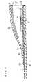
- FIG. 1is a vertical cross-sectional view of a glucose sensor of this example
- FIG. 2is an exploded perspective view of the glucose sensor, omitting the reagent layers and surface active agent layer therefrom.
- a silver pastewas printed on an electrically insulating base plate 1 made of polyethylene terephthalate by screen printing to form leads 2 and 3 and the base of later-described electrodes. Then, a conductive carbon paste containing a resin binder was printed on the base plate 1 to form a working electrode 4. This working electrode 4 was in contact with the lead 2. Further, an insulating paste was printed on the base plate 1 to form an insulating layer 6. The insulating layer 6 covered the peripheral portion of the working electrode 4 so that a fixed area of the working electrode 4 was exposed. Next, a counter electrode 5 was formed by printing a conductive carbon paste containing a resin binder so as to be in contact with the lead 3.
- a first aqueous solution containing GOD as an enzyme and no electron mediatorwas dropped on the working electrode 4 of the base plate 1 and then dried to form a first reagent layer 7.
- a second aqueous solution containing potassium ferricyanide as an electron mediator and no enzymewas dropped on the counter electrode 5 of the base plate 1 and then dried to form a second reagent layer 8.
- a layer 9 containing lecithin as a surface active agentwas formed so as to cover the first reagent layer 7 and the second reagent layer 8.
- the base plate 1, a cover 12 and a spacer 10were adhered to each other in a positional relationship as shown by the dashed lines in FIG. 2 to fabricate the glucose sensor.
- the spacer 10 to be inserted between the base plate 1 and the cover 12has a slit 11 for forming a sample solution supply pathway between the base plate 1 and the cover 12.
- FIG. 7is a vertical cross-sectional view of the glucose sensor of the comparative example.
- a reagent layer 30was formed by dropping an aqueous solution containing GOD and potassium ferricyanide on the working electrode 4 and counter electrode 5 and then drying the aqueous solution.
- a layer 9 containing lecithin as a surface active agentwas formed on the reagent layer 30.
- the concentration of glucosewas measured using a solution containing a certain amount of glucose as a sample.
- the samplewas supplied to the sample solution supply pathway from the sample supply port 13 and, after elapse of a certain time, a voltage of 500 mV was applied to the working electrode 4 using the counter electrode 5 as reference. Since the spacer 10 is interposed between the cover 12 and the base plate 1, the strength of the sensor against an external physical pressure is increased. Consequently, the volume of the sample solution supply pathway is readily kept constant, and the effects of physical pressure, etc. on the current response are reduced.
- Example 1The value of a current which flowed across the working electrode 4 and the counter electrode 5 upon the application of this voltage was measured. As a result, in both of Example 1 and the comparative example, a current response proportional to the glucose concentration in the sample was observed.
- potassium ferricyanideAs the oxidized form of the electron mediator dissociates into ferricyanide ion and potassium ion.
- the glucose in the sample, the ferricyanide ion dissolved in the sample from the second reagent layer 8 and the GODreact with each other.
- the glucoseis oxidized into glucono lactone, and the oxidized form ferricyanide ion is reduced to the reduced form ferrocyanide ion.
- a reaction of oxidizing ferrocyanide ion into ferricyanide ionproceeds on the working electrode 4, while a reaction of reducing ferricyanide ion into ferrocyanide ion proceeds on the counter electrode 5. Since the concentration of ferrocyanide ion is proportional to the concentration of glucose, it is possible to measure the concentration of glucose based on the oxidation current of the ferrocyanide ion.
- the enzyme reactionhardly proceeds at the counter electrode.
- sufficient concentration of potassium ferricyanideis retained on the counter electrode, preventing the reaction at the counter electrode from becoming a rate determining step even when the sample contains a substrate at high concentrations.
- the enzyme reactionproceeds on the counter electrode to the extent which is almost equivalent to that on the working electrode, causing reduction of ferricyanide ion into ferrocyanide ion. Consequently, the ferricyanide ion becomes insufficient for the reaction on the counter electrode, so that the reaction at the counter electrode becomes a rate determining step.
- the blank responsewas lowered and the current response was not changed so much even after a long-time storage in comparison with the glucose sensor of the comparative example. This is because GOD and potassium ferricyanide were separated from each other so that it was possible to prevent contact and interaction between GOD and potassium ferricyanide, thereby suppressing an increase in the blank response and degradation in the enzyme activity during a long-time storage.
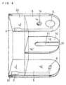
- FIG. 3is a vertical cross-sectional view of a glucose sensor of this example
- FIG. 4is a perspective view of the glucose sensor, omitting the reagent layers and surface active agent layer therefrom.
- a working electrode 4 and a lead 2were formed by sputtering palladium on an electrically insulating base plate 21. Next, by pasting an insulating sheet 23 on the base plate 21, the working electrode 4 and a terminal section to be inserted into a measurement device were defined.
- a counter electrode 5was formed by sputtering palladium onto the inner wall surface of an outwardly expanded curved section 24 of an electrically insulating cover member 22. An end portion of the curved section 24 was provided with an air vent 14.
- a first aqueous solution containing GOD as an enzyme and no electron mediatorwas dropped on the working electrode 4 of the base plate 21 and then dried to form a first reagent layer 7.
- a second aqueous solution containing potassium ferricyanide as an electron mediator and no enzymewas dropped on the counter electrode 5 of the cover member 22 to form a second reagent layer 8.
- a layer 9 containing lecithin as a surface active agentwas formed on the first reagent layer 7.
- the base plate 21 and cover 22were adhered to each other to fabricate the glucose sensor. Accordingly, the working electrode 4 and the counter electrode 5 are positioned to face each other with a space formed between the base plate 21 and the curved section 24 of the cover member 22 therebetween.
- This spaceserves as a sample storage section and, when a sample is brought into contact with an open end of the space, the sample readily moves toward the air vent 14 due to capillary phenomenon and comes into contact with the first reagent layer 7 and second reagent layer 8.
- the concentration of glucosewas measured according to the same procedure as in Example 1. As a result, a current response proportional to the concentration of glucose in the sample was observed.
- the counter electrode 5was electrically connected by holding an end portion of the curved section 24 with a clip connected to a lead wire.
- the second reagent layer 8contained only potassium ferricyanide, so that high linearity was observed up to a higher glucose concentration than in the glucose sensor of the comparative example, like Example 1. Also, in this biosensor, like Example 1, the blank response was lowered, and the current response was not changed so much even after a long-time storage in comparison with the comparative example, since GOD and potassium ferricyanide were separated from each other. Further, in comparison with the comparative example, an increase in the response value was observed, because the working electrode 4 and counter electrode 5 were formed at opposite positions so that ion transfer between the electrodes was facilitated.
- FIG.5is a vertical cross-sectional view of a glucose sensor of this example
- FIG. 6is an exploded perspective view of the glucose sensor, omitting the reagent layers and surface active agent layer therefrom.
- a silver pastewas printed on an electrically insulating base plate 31 made of polyethylene terephthalate by screen printing to form a lead 2. Then, a conductive carbon paste containing a resin binder was printed on the base plate 31 to form a working electrode 4. This working electrode 4 was in contact with the lead 2. Further, an insulating paste was printed on the base plate 31 to form an insulating layer 6. The insulating layer 6 covered the peripheral portion of the working electrode 4 so that a fixed area of the working electrode 4 was exposed.
- a silver pastewas printed on the inner surface of an electrically insulating cover 32 to form a lead 3, and then a conductive carbon paste was printed to form a counter electrode 5. Further, an insulating paste was printed to form an insulating layer 6.
- the cover 32was provided with an air vent 14.
- a first aqueous solution containing GOD as an enzyme and no electron mediatorwas dropped on the working electrode 4 of the base plate 31 and then dried to form a first reagent layer 7, while a second aqueous solution containing potassium ferricyanide as an electron mediator and no enzyme was dropped on the counter electrode 5 of the cover 32 and then dried to form a second reagent layer 8. Further, a layer 9 containing lecithin as a surface active agent was formed on the first reagent layer 7.
- the spacer 10 interposed between the base plate 31 and the cover 32has a slit 11 for forming a sample solution supply pathway between the base plate 31 and the cover 32.
- the working electrode 4 and counter electrode 5are positioned to face each other in the sample solution supply pathway formed in the slit 11 of the spacer 10.
- the air vent 14 of the cover 32communicates with this sample solution supply pathway, when a sample is brought into contact with a sample supply port 13 formed at an open end of the slit 11, the sample readily reaches the first reagent layer 7 and second reagent layer 8 in the sample solution supply pathway because of capillary phenomenon.
- the second reagent layer 8contained only potassium ferricyanide, so that high linearity was observed up to a higher glucose concentration than in the glucose sensor of the comparative example, like Example 1. Also, since the working electrode 4 and the counter electrode 5 were formed at opposite positions, the current response was increased in comparison with the comparative example, like Example 2.
- the spacer 10was interposed between the base plate 31 and cover 32, the strength of the sensor against an external physical pressure was enhanced. As a result, the first reagent layer 7 and the second reagent layer 8 were never brought into contact with each other by the physical pressure, thereby preventing the current response from being varied by the degradation of the enzyme activity caused by the contact between GOD and potassium ferricyanide. In addition, since the volume of the sample solution supply pathway was readily kept constant, the stability of the current response was improved in comparison with Example 2.
- a glucose sensorwas fabricated in the same manner as in Example 3 with the exception of the process of forming the first reagent layer 7 and second reagent layer 8.
- a first aqueous solution containing GOD as an enzyme, carboxymethyl cellulose as a hydrophilic polymer and no electron mediatorwas dropped on the working electrode 4 of the base plate 31 and then dried to form a first reagent layer 7, while a second aqueous solution containing potassium ferricyanide as an electron mediator, carboxymethyl cellulose and no enzyme was dropped on the counter electrode 5 of the cover 32 and then dried to form a second reagent layer 8.
- the layer 9 containing lecithin as a surface active agentwas formed on the first reagent layer 7.
- the second reagent layer 8contained only potassium ferricyanide, so that high linearity was observed up to a higher glucose concentration than in the glucose sensor of the comparative example, like Example 1. Also, since the working electrode 4 and the counter electrode 5 were formed at opposite positions, an increase in the response value was observed in comparison with the comparative example.
- the voltageis not necessarily limited to 500 mV. Any voltage that enables oxidation of the electron mediator reduced with the enzyme reaction may be applied.
- the second reagent layer formed on the counter electrodecontained only the electron mediator, but it may contain other components than the electron mediator as long as the inclusion of such components does not make the reaction at the counter electrode a rate determining step and the influence it may have on the blank response and storage stability is so small as to be negligible.
- the first reagent layer formed on the working electrodecontained either only the enzyme or the enzyme and the hydrophilic polymer, but it may also contain the other components as long as the influence such inclusion may have on the blank response and storage stability is so small as to be negligible.
- the first reagent layer 7 and second reagent layer 8may be immobilized on the working electrode 4 or the counter electrode 5 so as to insolubilize the enzyme or the electron mediator.
- the electron mediator and the enzymemay be mixed into the working electrode and the counter electrode, respectively.
- the surface active agentit is possible to use a material other than lecithin.
- the surface active agent layer 9was formed only on the first reagent layer 7, or on the first reagent layer 7 and second reagent layer 8, the formation of the surface active agent layer 9 is not necessarily limited to these examples, and the surface active agent layer 9 may be formed at a position facing the sample solution supply pathway, such as a side face of the slit 11 of the spacer 10.
- first reagent layer 7 and the second reagent layer 8are not in contact with each other and are separated from each other with a space interposed therebetween. Accordingly, it is possible to further enhance the effect of suppressing an increase in the blank response and the effect of improving the storage stability.
- the present inventionit is possible to obtain a biosensor having a favorable current response characteristic up to a high concentration range. Further, it is possible to obtain a biosensor having a low blank response and a high storage stability.
Landscapes
- Chemical & Material Sciences (AREA)
- Organic Chemistry (AREA)
- Life Sciences & Earth Sciences (AREA)
- Zoology (AREA)
- Wood Science & Technology (AREA)
- Proteomics, Peptides & Aminoacids (AREA)
- Health & Medical Sciences (AREA)
- Engineering & Computer Science (AREA)
- Microbiology (AREA)
- Biochemistry (AREA)
- Physics & Mathematics (AREA)
- Molecular Biology (AREA)
- Biotechnology (AREA)
- Biophysics (AREA)
- Analytical Chemistry (AREA)
- Immunology (AREA)
- Bioinformatics & Cheminformatics (AREA)
- General Engineering & Computer Science (AREA)
- General Health & Medical Sciences (AREA)
- Genetics & Genomics (AREA)
- Apparatus Associated With Microorganisms And Enzymes (AREA)
- Measuring Or Testing Involving Enzymes Or Micro-Organisms (AREA)
- Investigating Or Analysing Biological Materials (AREA)
Description
- The present invention relates to a biosensor forrapid quantification of a substrate contained in a samplewith high accuracy.
- Conventionally, methods using polarimetry,colorimetry, reductimetry and a variety of chromatographyhave been developed as the measure for quantitativeanalysis of sugars such as sucrose and glucose. However,those conventional methods are all poorly specific tosugars and hence have poor accuracy. Among them, thepolarimetry is simple in manipulation, but it is largelyaffected by the temperature during the manipulation.Therefore, this method is not suitable for simplequantification of sugars at home by ordinary people.
- In recent years, a variety of biosensors havebeen developed which best utilize a specific catalyticaction of enzymes.
- In the following, a method of quantitativeanalysis of glucose will be explained as an example of themethod for quantifying a substrate contained in a sample.Conventionally known electrochemical quantification ofglucose includes a method using a combination of glucose oxidase (EC 1.1.3.4: hereinafter abbreviated to "GOD") asan enzyme with an oxygen electrode or a hydrogen peroxideelectrode (see "Biosensor" ed. by Shuichi Suzuki, Kodansha,for example).
- GOD selectively oxidizes β-D-glucose as asubstrate to D-glucono-δ-lactone using oxygen as anelectron mediator. Oxygen is reduced to hydrogen peroxideduring the oxidation reaction by GOD in the presence ofoxygen. A decreased volume of oxygen is measured by theoxygen electrode, or an increased volume of hydrogenperoxide is measured by the hydrogen peroxide electrode.The decreased volume of oxygen or, otherwise, the increasedvolume of hydrogen peroxide is proportional to the contentof glucose in the sample. It is therefore possible toquantify glucose based on the decreased volume of oxygen orthe increased volume of hydrogen peroxide.
- In the above method, it is possible to quantifyglucose in the sample accurately by using the specificityof the enzyme reaction. However, as speculated from thereaction, this prior art method has a drawback that themeasurement result is greatly affected by the oxygenconcentration in the sample. Hence, in the event whereoxygen is absent in the sample, measurement is infeasible.
- Under such a circumstance, a glucose sensor ofnew type has been developed which uses as the electron mediator an organic compound or a metal complex such aspotassium ferricyanide, a ferrocene derivative and aquinone derivative, in place of oxygen in the sample. Thesensor of this type oxidizes the reduced electron mediatorresulting from the enzyme reaction on a working electrodeso as to determine the glucose concentration in the samplebased on an oxidation current produced by the oxidationreaction. At this time, on a counter electrode, theoxidized electron mediator is reduced, and a reaction forgenerating the reduced electron mediator proceeds. Withthe use of such an organic compound or metal complex as theelectron mediator in place of oxygen, it is possible toform a reagent layer by precisely placing a known amount ofGOD together with the electron mediator in their stablestate on the electrode, thereby enabling accuratequantification of glucose without being affected by theoxygen concentration in the sample. In this case, it isalso possible to integrate the reagent layer containing theenzyme and electron mediator with an electrode system whilekeeping the reagent layer in an almost dry state, andtherefore a disposable glucose sensor based on thistechnology has recently been noted considerably. A typicalexample of such a glucose sensor is a biosensor disclosedin Japanese Laid-Open Patent Publication Hei 3-202764.With such a disposable glucose sensor, it is possible to measure the glucose concentration easily with a measurementdevice by simply introducing a sample into the sensorconnected detachably to the measurement device. Theapplication of such a technique is not limited toquantification of glucose and may be extended toquantification of any other substrate contained in thesample.
- However, in the above-described conventionalbiosensors, when the sample contains a substrate at highconcentrations, the enzyme reaction proceeds also on thecounter electrode and supply of the electron mediator tothe counter electrode thus becomes insufficient, so thatthe reaction at the counter electrode becomes a ratedetermining step, which makes it impossible to obtain acurrent response proportional to the substrateconcentration. Therefore, such biosensors have a problemthat quantification of a substrate is not possible when thesample contains a substrate at high concentrations.
- In recent years, there is a demand for abiosensor exhibiting a low response when the substrateconcentration is zero and excellent storage stability. Theresponse obtained when the substrate concentration is zerois hereinafter referred to as "blank response".
- The present invention provides a biosensor comprising: an electrode systemincluding a working electrode and a counter electrode, for forming an electrochemicalmeasurement system by coming in contact with a supplied sample solution; anelectrically insulating supporting member for supporting the electrode system; a firstreagent layer formed on the working electrode; and a second reagent layer formed onthe counter electrode, wherein the first reagent layer does not contain an electronmediator and comprises an enzyme as the main component, and the second reagentlayer does not contain an enzyme and comprises an electron mediator as the maincomponent.
- In a preferred mode of the present invention, the supporting member comprisesan electrically insulating base plate on which the working electrode and the counterelectrode are formed.
- In another preferred mode of the present invention, the supporting membercomprises an electrically insulating base plate and an electrically insulating covermember for forming a sample solution supply pathway or a sample solution storagesection between the cover member and the base plate, the working electrode is formedon the base plate, and the counter electrode is formed on an inner surface of the cover member so as to face the workingelectrode.
- It is preferred that the cover member comprises asheet member having an outwardly expanded curved section,for forming a sample solution supply pathway or a samplesolution storage section between the cover member and thebase plate.
- In a more preferred mode of the present invention,the cover member comprises a spacer having a slit forforming the sample solution supply pathway and a cover forcovering the spacer.
- It is preferred that at least the first reagentlayer contains a hydrophilic polymer.
- While the novel features of the invention are setforth particularly in the appended claims, the invention,both as to organization and content, will be betterunderstood and appreciated, along with other objects andfeatures thereof, from the following detailed descriptiontaken in conjunction with the drawings.
- FIG. 1 is a vertical cross-sectional view of aglucose sensor according to one example of the presentinvention.
- FIG. 2 is an exploded perspective view of the glucose sensor, omitting the reagent layers and surfaceactive agent layer therefrom.
- FIG. 3 is a vertical cross-sectional view of aglucose sensor according to another example of the presentinvention.
- FIG. 4 is a perspective view of theglucose sensor, omitting the reagent layers and surfaceactive agent layer therefrom.
- FIG.5 is a vertical cross-sectional view of aglucose sensor according to still another example of thepresent invention.
- FIG. 6 is an exploded perspective view of theglucose sensor, omitting the reagent layers and surfaceactive agent layer therefrom.
- Fig. 7 is a vertical cross-sectional view of aglucose sensor of a comparative example.
- A biosensor in accordance with a preferred modeof the present invention comprises an electricallyinsulating base plate; a working electrode and a counterelectrode formed on the base plate; a first reagent layerformed on the working electrode; and a second reagent layerformed on the counter electrode, wherein the first reagentlayer does not contain an electron mediator and comprises an enzyme as the maincomponent, and the second reagent layer does not contain an enzyme and comprises an electron mediatoras the main component.
- In this biosensor, the enzyme reaction hardlyproceeds at the counter electrode especially when thesample contains a substrate at high concentrations, sincethe main component of the second reagent layer on thecounter electrode is the electron mediator. Thus, theprobability of collision between the enzyme and theelectron mediator decreases in the sample solution in whichthe reagents are dissolved, so that the linearity ofresponse current is decreased. However, since sufficientelectron mediator is retained on the counter electrode forthe reaction, the reaction at the counter electrode doesnot become a rate determining step. As a result, thelinearity of response current can be maintained even up toa high substrate-concentration range.
- A biosensor in accordance with another preferredmode of the present invention comprises an electricallyinsulating base plate; an electrically insulating covermember for forming a sample solution supply pathway or asample solution storage section between the cover memberand the base plate; a working electrode formed on the baseplate; a counter electrode formed on an inner surface ofthe cover member so as to face the working electrode; afirst reagent layer formed on the working electrode; and a second reagent layer formed on the counter electrode.
- The cover member comprises a sheet member havingan outwardly expanded curved section, for forming a samplesolution supply pathway or a sample solution storagesection between the cover member and the base plate.
- A more preferred cover member comprises a spacerwith a slit for forming the sample solution supply pathwayand a cover for covering the spacer.
- In such a biosensor, since the first reagentlayer and second reagent layer are formed on separatemembers, respectively, the first reagent layer and secondreagent layer having different compositions can be readilyseparated from each other. Moreover, since the workingelectrode and counter electrode are formed at oppositepositions, the ion tranfer between the electrodes isfacilitated, thereby further increasing the currentresponse.
- In a biosensor whose cover member comprises thespacer and cover, since the physical strength of the coveris enhanced, the first reagent layer and second reagentlayer are not brought into contact with each other by anexternal physical pressure, thereby preventing degradationin the enzyme activity due to the contact between theenzyme and the electron mediator.
- In either of the biosensors of the above-described embodiments, it is preferred that at least thefirst reagent layer contains a hydrophilic polymer. Sincethe hydrophilic polymer prevents adsorption of proteins,etc. to the working electrode, the current responsesensitivity is further improved. Besides, during themeasurement, since the viscosity of a sample solution isincreased by the hydrophilic polymer dissolved in thesample solution, the effects of physical impact, etc. onthe current response are reduced, thereby improving thestability of the current response.
- In the present invention, for the base plate,spacer and cover, it is possible to use any material havingan insulating property and sufficient rigidity duringstorage and measurement. Examples of such a materialinclude thermoplastic resins such as polyethylene,polystyrene, polyvinyl chloride, polyamide and saturatedpolyester resin, or thermosetting resins such as a urearesin, melamine resin, phenol resin, epoxy resin andunsaturated polyester resin. Among these resins,polyethylene terephthalate is preferred in view of theadhesiveness to the electrode.
- For the working electrode, it is possible to useany conductive material if it is not oxidized itself inoxidizing the electron mediator. For the counter electrode,it is possible to use a generally used conductive material such as palladium, silver, platinum, and carbon.
- As the enzyme, it is possible to use the onesuitable for the type of a substrate in the sample, whichis the subject of measurement. Examples of the enzymeinclude fructose dehydrogenase, glucose oxidase, alcoholoxidase, lactate oxidase, cholesterol oxidase, xanthineoxidase, and amino acid oxidase.
- Examples of the electron mediator includepotassium ferricyanide, p-benzoquinone, phenazinemethosulfate, methylene blue, and ferrocene derivatives.Besides, even when oxygen is used as the electron mediator,a current response is obtained. These electron mediatorsare used singly or in combinations of two or more.
- A variety of hydrophilic polymers are applicable.Examples of the hydrophilic polymer include hydroxyethylcellulose, hydroxypropyl cellulose, methyl cellulose, ethylcellulose, ethylhydroxyethyl cellulose, carboxymethylcellulose, polyvinyl pyrrolidone, polyvinyl alcohol,polyamino acid such as polylysine, polystyrene sulfonate,gelatin and its derivatives, polyacrylic acid and its salts,polymethacrylic acid and its salts, starch and itsderivatives, and a polymer of maleic anhydride or a maleate.Among them, carboxymethyl cellulose, hydroxyethyl celluloseand hydroxypropyl cellulose are particularly preferred.
- The following description will explain the present invention in further detail by illustratingexamples thereof.
- A glucose sensor will be explained as an exampleof a biosensor.
- FIG. 1 is a vertical cross-sectional view of aglucose sensor of this example, and FIG. 2 is an explodedperspective view of the glucose sensor, omitting thereagent layers and surface active agent layer therefrom.
- First, a silver paste was printed on anelectrically insulating base plate 1 made of polyethyleneterephthalate by screen printing to form leads 2 and 3 andthe base of later-described electrodes. Then, a conductivecarbon paste containing a resin binder was printed on thebase plate 1 to form a working
electrode 4. This workingelectrode 4 was in contact with thelead 2. Further, aninsulating paste was printed on the base plate 1 to form aninsulatinglayer 6. The insulatinglayer 6 covered theperipheral portion of the workingelectrode 4 so that afixed area of the workingelectrode 4 was exposed. Next, acounter electrode 5 was formed by printing a conductivecarbon paste containing a resin binder so as to be incontact with thelead 3. - A first aqueous solution containing GOD as an enzyme and no electron mediator was dropped on the working
electrode 4 of the base plate 1 and then dried to form afirst reagent layer 7. Besides, a second aqueous solutioncontaining potassium ferricyanide as an electron mediatorand no enzyme was dropped on thecounter electrode 5 of thebase plate 1 and then dried to form asecond reagent layer 8. Further, in order to achieve smooth supply of a sample,alayer 9 containing lecithin as a surface active agent wasformed so as to cover thefirst reagent layer 7 and thesecond reagent layer 8. - Finally, the base plate 1, a
cover 12 and aspacer 10 were adhered to each other in a positionalrelationship as shown by the dashed lines in FIG. 2 tofabricate the glucose sensor. - The
spacer 10 to be inserted between the baseplate 1 and thecover 12 has aslit 11 for forming a samplesolution supply pathway between the base plate 1 and thecover 12. - Since an
air vent 14 of thecover 12 communicateswith this sample solution supply pathway, when the sampleis brought into contact with asample supply port 13 formedat an open end of theslit 11, the sample readily reachesthefirst reagent layer 7 andsecond reagent layer 8 in thesample solution supply pathway because of capillaryphenomenon. - As a comparative example, a glucose sensor wasfabricated in the same manner as this example with theexception of the process of forming the reagent layers.FIG. 7 is a vertical cross-sectional view of the glucosesensor of the comparative example. A
reagent layer 30 wasformed by dropping an aqueous solution containing GOD andpotassium ferricyanide on the workingelectrode 4 andcounter electrode 5 and then drying the aqueous solution.Moreover, alayer 9 containing lecithin as a surface activeagent was formed on thereagent layer 30. - Next, with the glucose sensors of Example 1 andthe comparative example, the concentration of glucose wasmeasured using a solution containing a certain amount ofglucose as a sample. The sample was supplied to the samplesolution supply pathway from the
sample supply port 13 and,after elapse of a certain time, a voltage of 500 mV wasapplied to the workingelectrode 4 using thecounterelectrode 5 as reference. Since thespacer 10 isinterposed between thecover 12 and the base plate 1, thestrength of the sensor against an external physicalpressure is increased. Consequently, the volume of thesample solution supply pathway is readily kept constant,and the effects of physical pressure, etc. on the currentresponse are reduced. - The value of a current which flowed across the working
electrode 4 and thecounter electrode 5 upon theapplication of this voltage was measured. As a result, inboth of Example 1 and the comparative example, a currentresponse proportional to the glucose concentration in thesample was observed. When the sample comes into contactwith thefirst reagent layer 7 and thesecond reagent layer 8, potassium ferricyanide as the oxidized form of theelectron mediator dissociates into ferricyanide ion andpotassium ion. The glucose in the sample, the ferricyanideion dissolved in the sample from thesecond reagent layer 8and the GOD react with each other. As a result, theglucose is oxidized into glucono lactone, and the oxidizedform ferricyanide ion is reduced to the reduced formferrocyanide ion. A reaction of oxidizing ferrocyanide ioninto ferricyanide ion proceeds on the workingelectrode 4,while a reaction of reducing ferricyanide ion intoferrocyanide ion proceeds on thecounter electrode 5.Since the concentration of ferrocyanide ion is proportionalto the concentration of glucose, it is possible to measurethe concentration of glucose based on the oxidation currentof the ferrocyanide ion. - In the glucose sensor of this example, highlinearity was observed up to a higher glucose concentrationthan in the glucose sensor of the comparative example forthe following reasons.
- Since GOD and potassium ferricyanide areseparately carried on the working electrode and the counterelectrode, respectively, the enzyme reaction hardlyproceeds at the counter electrode. Thus, sufficientconcentration of potassium ferricyanide is retained on thecounter electrode, preventing the reaction at the counterelectrode from becoming a rate determining step even whenthe sample contains a substrate at high concentrations. As'a result, it is possible to maintain the linearity ofresponse current up to a high concentration range. In thesensor of the comparative example, on the other hand, theenzyme reaction proceeds on the counter electrode to theextent which is almost equivalent to that on the workingelectrode, causing reduction of ferricyanide ion intoferrocyanide ion. Consequently, the ferricyanide ionbecomes insufficient for the reaction on the counterelectrode, so that the reaction at the counter electrodebecomes a rate determining step.
- Further, in the glucose sensor of this example,the blank response was lowered and the current response wasnot changed so much even after a long-time storage incomparison with the glucose sensor of the comparativeexample. This is because GOD and potassium ferricyanidewere separated from each other so that it was possible toprevent contact and interaction between GOD and potassium ferricyanide, thereby suppressing an increase in the blankresponse and degradation in the enzyme activity during along-time storage.
- FIG. 3 is a vertical cross-sectional view of aglucose sensor of this example, and FIG. 4 is aperspective view of the glucose sensor, omitting thereagent layers and surface active agent layer therefrom.
- A working
electrode 4 and alead 2 were formed bysputtering palladium on an electrically insulatingbaseplate 21. Next, by pasting an insulatingsheet 23 on thebase plate 21, the workingelectrode 4 and a terminalsection to be inserted into a measurement device weredefined. - Meanwhile, a
counter electrode 5 was formed bysputtering palladium onto the inner wall surface of anoutwardly expandedcurved section 24 of an electricallyinsulatingcover member 22. An end portion of thecurvedsection 24 was provided with anair vent 14. - A first aqueous solution containing GOD as anenzyme and no electron mediator was dropped on the working
electrode 4 of thebase plate 21 and then dried to form afirst reagent layer 7. Besides, a second aqueous solutioncontaining potassium ferricyanide as an electron mediator and no enzyme was dropped on thecounter electrode 5 of thecover member 22 to form asecond reagent layer 8. Further,alayer 9 containing lecithin as a surface active agent wasformed on thefirst reagent layer 7. - Finally, the
base plate 21 and cover 22 wereadhered to each other to fabricate the glucose sensor.Accordingly, the workingelectrode 4 and thecounterelectrode 5 are positioned to face each other with a spaceformed between thebase plate 21 and thecurved section 24of thecover member 22 therebetween. This space serves asa sample storage section and, when a sample is brought intocontact with an open end of the space, the sample readilymoves toward theair vent 14 due to capillary phenomenonand comes into contact with thefirst reagent layer 7 andsecond reagent layer 8. - Next, the concentration of glucose was measuredaccording to the same procedure as in Example 1. As aresult, a current response proportional to theconcentration of glucose in the sample was observed. The
counter electrode 5 was electrically connected by holdingan end portion of thecurved section 24 with a clipconnected to a lead wire. - In the glucose sensor of Example 2, the
secondreagent layer 8 contained only potassium ferricyanide, sothat high linearity was observed up to a higher glucose concentration than in the glucose sensor of the comparativeexample, like Example 1. Also, in this biosensor, likeExample 1, the blank response was lowered, and the currentresponse was not changed so much even after a long-timestorage in comparison with the comparative example, sinceGOD and potassium ferricyanide were separated from eachother. Further, in comparison with the comparative example,an increase in the response value was observed, because theworkingelectrode 4 andcounter electrode 5 were formed atopposite positions so that ion transfer between theelectrodes was facilitated. - FIG.5 is a vertical cross-sectional view of aglucose sensor of this example, and FIG. 6 is an explodedperspective view of the glucose sensor, omitting thereagent layers and surface active agent layer therefrom.
- First, a silver paste was printed on anelectrically insulating
base plate 31 made of polyethyleneterephthalate by screen printing to form alead 2. Then, aconductive carbon paste containing a resin binder wasprinted on thebase plate 31 to form a workingelectrode 4.This workingelectrode 4 was in contact with thelead 2.Further, an insulating paste was printed on thebase plate 31 to form an insulatinglayer 6. The insulatinglayer 6 covered the peripheral portion of the workingelectrode 4so that a fixed area of the workingelectrode 4 was exposed. - Next, a silver paste was printed on the innersurface of an electrically insulating
cover 32 to form alead 3, and then a conductive carbon paste was printed toform acounter electrode 5. Further, an insulating pastewas printed to form an insulatinglayer 6. Thecover 32was provided with anair vent 14. - A first aqueous solution containing GOD as anenzyme and no electron mediator was dropped on the working
electrode 4 of thebase plate 31 and then dried to form afirst reagent layer 7, while a second aqueous solutioncontaining potassium ferricyanide as an electron mediatorand no enzyme was dropped on thecounter electrode 5 of thecover 32 and then dried to form asecond reagent layer 8.Further, alayer 9 containing lecithin as a surface activeagent was formed on thefirst reagent layer 7. - Finally, the
base plate 31, thecover 32 and aspacer 10 were adhered to each other in a positionalrelationship as shown by the dashed lines of FIG. 6 tofabricate the glucose sensor. - The
spacer 10 interposed between thebase plate 31 and thecover 32 has aslit 11 for forming a samplesolution supply pathway between thebase plate 31 and thecover 32. The workingelectrode 4 andcounter electrode 5 are positioned to face each other in the sample solutionsupply pathway formed in theslit 11 of thespacer 10. - Since the
air vent 14 of thecover 32communicates with this sample solution supply pathway, whena sample is brought into contact with asample supply port 13 formed at an open end of theslit 11, the sample readilyreaches thefirst reagent layer 7 andsecond reagent layer 8 in the sample solution supply pathway because ofcapillary phenomenon. - Next, the concentration of glucose was measuredaccording to the same procedure as in Example 1. As aresult of the measurement, a current response proportionalto the concentration of glucose in the sample was observed.
- In the glucose sensor of Example 3, the
secondreagent layer 8 contained only potassium ferricyanide, sothat high linearity was observed up to a higher glucoseconcentration than in the glucose sensor of the comparativeexample, like Example 1. Also, since the workingelectrode 4 and thecounter electrode 5 were formed at oppositepositions, the current response was increased in comparisonwith the comparative example, like Example 2. - Moreover, since the GOD and potassiumferricyanide were separated from each other, like Example 1,the blank response was lowered and the current response wasnot changed so much even after a long-time storage in comparison with the comparative example.
- Furthermore, since the
spacer 10 was interposedbetween thebase plate 31 andcover 32, the strength of thesensor against an external physical pressure was enhanced.As a result, thefirst reagent layer 7 and thesecondreagent layer 8 were never brought into contact with eachother by the physical pressure, thereby preventing thecurrent response from being varied by the degradation ofthe enzyme activity caused by the contact between GOD andpotassium ferricyanide. In addition, since the volume ofthe sample solution supply pathway was readily keptconstant, the stability of the current response wasimproved in comparison with Example 2. - In this embodiment, a glucose sensor wasfabricated in the same manner as in Example 3 with theexception of the process of forming the
first reagent layer 7 andsecond reagent layer 8. - A first aqueous solution containing GOD as anenzyme, carboxymethyl cellulose as a hydrophilic polymerand no electron mediator was dropped on the working
electrode 4 of thebase plate 31 and then dried to form afirst reagent layer 7, while a second aqueous solutioncontaining potassium ferricyanide as an electron mediator, carboxymethyl cellulose and no enzyme was dropped on thecounter electrode 5 of thecover 32 and then dried to formasecond reagent layer 8. Moreover, thelayer 9 containinglecithin as a surface active agent was formed on thefirstreagent layer 7. - Next, the concentration of glucose was measuredaccording to the same procedure as in Example 1. As aresult of the measurement, a current response proportionalto the concentration of glucose in the sample was observed.
- In the glucose sensor of this example, the
secondreagent layer 8 contained only potassium ferricyanide, sothat high linearity was observed up to a higher glucoseconcentration than in the glucose sensor of the comparativeexample, like Example 1. Also, since the workingelectrode 4 and thecounter electrode 5 were formed at oppositepositions, an increase in the response value was observedin comparison with the comparative example. - Moreover, since the GOD and potassiumferricyanide were separated from each other, the blankresponse was lowered and the current response was notchanged so much even after a long-time storage incomparison with the comparative example.
- Furthermore, since the
spacer 10 was interposedbetween thebase plate 31 andcover 32, it was possible toprevent the current response from being varied by the degradation in the enzyme activity caused by the contactbetween GOD and potassium ferricyanide. In addition, sincethe volume of the sample solution supply pathway wasreadily kept constant, the stability of the currentresponse was improved in comparison with Example 2. - Besides, in comparison with Examples 2 and 3, thecurrent response was further increased for the followingreason. The presence of carboxymethyl cellulose in the
first reagent layer 7 prevented adsorption of proteins tothe surface of the workingelectrode 4, and hence theelectrode reaction on the workingelectrode 4 proceededsmoothly. Furthermore, since the viscosity of the samplewas increased during the measurement, the effects ofphysical impact, etc. on the sensor were reduced andvariations in the sensor response were decreased. - In the above-described examples, while a voltageof 500 mV was applied to the working
electrode 4 using thecounter electrode 5 as reference, the voltage is notnecessarily limited to 500 mV. Any voltage that enablesoxidation of the electron mediator reduced with the enzymereaction may be applied. - In the foregoing examples, the second reagentlayer formed on the counter electrode contained only theelectron mediator, but it may contain other components thanthe electron mediator as long as the inclusion of such components does not make the reaction at the counterelectrode a rate determining step and the influence it mayhave on the blank response and storage stability is sosmall as to be negligible. Also, in those examples, thefirst reagent layer formed on the working electrodecontained either only the enzyme or the enzyme and thehydrophilic polymer, but it may also contain the othercomponents as long as the influence such inclusion may haveon the blank response and storage stability is so small asto be negligible.
- In the above-described examples, only one kind ofelectron mediator was used, but two or more kinds ofelectron mediators may be used.
- The
first reagent layer 7 andsecond reagentlayer 8 may be immobilized on the workingelectrode 4 orthecounter electrode 5 so as to insolubilize the enzyme orthe electron mediator. In the case where thefirst reagentlayer 7 andsecond reagent layer 8 are immobilized, it ispreferable to use a crosslinking immobilization method oran adsorption method. Alternatively, the electron mediatorand the enzyme may be mixed into the working electrode andthe counter electrode, respectively. - As the surface active agent, it is possible touse a material other than lecithin. Besides, in the above-describedexamples, although the surface
active agent layer 9 was formed only on thefirst reagent layer 7, or on thefirst reagent layer 7 andsecond reagent layer 8, theformation of the surfaceactive agent layer 9 is notnecessarily limited to these examples, and the surfaceactive agent layer 9 may be formed at a position facing thesample solution supply pathway, such as a side face of theslit 11 of thespacer 10. - In the above-described examples, a two-electrodesystem consisting only of the working electrode and counterelectrode is described. However, if a three-electrodesystem including an additional reference electrode isadopted, it is possible to perform a more accuratemeasurement.
- It is preferred that the
first reagent layer 7and thesecond reagent layer 8 are not in contact with eachother and are separated from each other with a spaceinterposed therebetween. Accordingly, it is possible tofurther enhance the effect of suppressing an increase inthe blank response and the effect of improving the storagestability. - As described above, according to the presentinvention, it is possible to obtain a biosensor having afavorable current response characteristic up to a highconcentration range. Further, it is possible to obtain abiosensor having a low blank response and a high storage stability.
- Although the present invention has been describedin terms of the presently preferred embodiments, it is tobe understood that such disclosure is not to be interpretedas limiting. Various alterations and modifications will nodoubt become apparent to those skilled in the art to whichthe present invention pertains, after having read the abovedisclosure.
Claims (6)
- A biosensor comprising:wherein said first reagent layer (7) does not contain an electron mediator andcomprises an enzyme as the main component, and said second reagent layer (8) doesnot contain an enzyme and comprises an electron mediator as the main component.an electrode system including a working electrode (4) and a counter electrode(5), for forming an electrochemical measurement system by coming in contact with asupplied sample solution;an electrically insulating supporting member (1,21,22,31,32) for supportingsaid electrode system;a first reagent layer (7) formed on said working electrode (4); anda second reagent layer (8) formed on said counter electrode (5),
- The biosensor in accordance with claim 1,
wherein said supporting member comprises an electrically insulating base plate(1) on which said working electrode (4) and said counter electrode (5) are formed. - The biosensor in accordance with claim 1,
wherein said supporting member comprises an electrically insulating base plate(21,31) and an electrically insulating cover member (22,32) for forming a samplesolution supply pathway or a sample solution storage section between said covermember (22,32) and said base plate (21,31),
said working electrode (4) is formed on said base plate (21,31), and
said counter electrode (5) is formed on an inner surface of said cover member(22,32) so as to face said working electrode (4). - The biosensor in accordance with claim 3,
wherein said cover member (22) comprises a sheet member having anoutwardly expanded curved section (24), for forming said sample solution supplypathway or said sample solution storage section between said cover member (22) andsaid base plate (21). - The biosensor in accordance with claim 3,
wherein said cover member comprises a spacer (10) having a slit (11) forforming said sample solution supply pathway and a cover (32) for covering said spacer(10). - The biosensor in accordance with any preceding claim,
wherein said first reagent layer (7) contains a hydrophilic polymer.
Applications Claiming Priority (2)
| Application Number | Priority Date | Filing Date | Title |
|---|---|---|---|
| JP36983699 | 1999-12-27 | ||
| JP36983699 | 1999-12-27 |
Publications (2)
| Publication Number | Publication Date |
|---|---|
| EP1126032A1 EP1126032A1 (en) | 2001-08-22 |
| EP1126032B1true EP1126032B1 (en) | 2005-04-20 |
Family
ID=18495437
Family Applications (1)
| Application Number | Title | Priority Date | Filing Date |
|---|---|---|---|
| EP00311655AExpired - LifetimeEP1126032B1 (en) | 1999-12-27 | 2000-12-22 | Biosensor |
Country Status (5)
| Country | Link |
|---|---|
| US (2) | US6599407B2 (en) |
| EP (1) | EP1126032B1 (en) |
| CN (1) | CN1172181C (en) |
| DE (1) | DE60019547T2 (en) |
| ES (1) | ES2238254T3 (en) |
Families Citing this family (131)
| Publication number | Priority date | Publication date | Assignee | Title |
|---|---|---|---|---|
| AU6157898A (en) | 1997-02-06 | 1998-08-26 | E. Heller & Company | Small volume (in vitro) analyte sensor |
| US6036924A (en) | 1997-12-04 | 2000-03-14 | Hewlett-Packard Company | Cassette of lancet cartridges for sampling blood |
| US8071384B2 (en) | 1997-12-22 | 2011-12-06 | Roche Diagnostics Operations, Inc. | Control and calibration solutions and methods for their use |
| US7494816B2 (en)* | 1997-12-22 | 2009-02-24 | Roche Diagnostic Operations, Inc. | System and method for determining a temperature during analyte measurement |
| US6103033A (en) | 1998-03-04 | 2000-08-15 | Therasense, Inc. | Process for producing an electrochemical biosensor |
| US6391005B1 (en) | 1998-03-30 | 2002-05-21 | Agilent Technologies, Inc. | Apparatus and method for penetration with shaft having a sensor for sensing penetration depth |
| US6294281B1 (en)* | 1998-06-17 | 2001-09-25 | Therasense, Inc. | Biological fuel cell and method |
| US6338790B1 (en) | 1998-10-08 | 2002-01-15 | Therasense, Inc. | Small volume in vitro analyte sensor with diffusible or non-leachable redox mediator |
| US20050103624A1 (en) | 1999-10-04 | 2005-05-19 | Bhullar Raghbir S. | Biosensor and method of making |
| ES2238254T3 (en)* | 1999-12-27 | 2005-09-01 | Matsushita Electric Industrial Co., Ltd. | BIOSENSOR |
| US8641644B2 (en) | 2000-11-21 | 2014-02-04 | Sanofi-Aventis Deutschland Gmbh | Blood testing apparatus having a rotatable cartridge with multiple lancing elements and testing means |
| US7005273B2 (en) | 2001-05-16 | 2006-02-28 | Therasense, Inc. | Method for the determination of glycated hemoglobin |
| JP4209767B2 (en) | 2001-06-12 | 2009-01-14 | ペリカン テクノロジーズ インコーポレイテッド | Self-optimized cutting instrument with adaptive means for temporary changes in skin properties |
| JP4272051B2 (en) | 2001-06-12 | 2009-06-03 | ペリカン テクノロジーズ インコーポレイテッド | Blood sampling apparatus and method |
| US7344507B2 (en) | 2002-04-19 | 2008-03-18 | Pelikan Technologies, Inc. | Method and apparatus for lancet actuation |
| AU2002344825A1 (en) | 2001-06-12 | 2002-12-23 | Pelikan Technologies, Inc. | Method and apparatus for improving success rate of blood yield from a fingerstick |
| US7041068B2 (en) | 2001-06-12 | 2006-05-09 | Pelikan Technologies, Inc. | Sampling module device and method |
| US9795747B2 (en) | 2010-06-02 | 2017-10-24 | Sanofi-Aventis Deutschland Gmbh | Methods and apparatus for lancet actuation |
| US7749174B2 (en) | 2001-06-12 | 2010-07-06 | Pelikan Technologies, Inc. | Method and apparatus for lancet launching device intergrated onto a blood-sampling cartridge |
| US8337419B2 (en) | 2002-04-19 | 2012-12-25 | Sanofi-Aventis Deutschland Gmbh | Tissue penetration device |
| WO2002101359A2 (en) | 2001-06-12 | 2002-12-19 | Pelikan Technologies, Inc. | Integrated blood sampling analysis system with multi-use sampling module |
| US9427532B2 (en) | 2001-06-12 | 2016-08-30 | Sanofi-Aventis Deutschland Gmbh | Tissue penetration device |
| EP1395185B1 (en) | 2001-06-12 | 2010-10-27 | Pelikan Technologies Inc. | Electric lancet actuator |
| US7981056B2 (en) | 2002-04-19 | 2011-07-19 | Pelikan Technologies, Inc. | Methods and apparatus for lancet actuation |
| US9226699B2 (en) | 2002-04-19 | 2016-01-05 | Sanofi-Aventis Deutschland Gmbh | Body fluid sampling module with a continuous compression tissue interface surface |
| US7052591B2 (en)* | 2001-09-21 | 2006-05-30 | Therasense, Inc. | Electrodeposition of redox polymers and co-electrodeposition of enzymes by coordinative crosslinking |
| KR100955587B1 (en)* | 2001-10-10 | 2010-04-30 | 라이프스캔, 인코포레이티드 | Electrochemical cell |
| US7344894B2 (en) | 2001-10-16 | 2008-03-18 | Agilent Technologies, Inc. | Thermal regulation of fluidic samples within a diagnostic cartridge |
| US9248267B2 (en) | 2002-04-19 | 2016-02-02 | Sanofi-Aventis Deustchland Gmbh | Tissue penetration device |
| US7410468B2 (en) | 2002-04-19 | 2008-08-12 | Pelikan Technologies, Inc. | Method and apparatus for penetrating tissue |
| US7232451B2 (en) | 2002-04-19 | 2007-06-19 | Pelikan Technologies, Inc. | Method and apparatus for penetrating tissue |
| US8267870B2 (en) | 2002-04-19 | 2012-09-18 | Sanofi-Aventis Deutschland Gmbh | Method and apparatus for body fluid sampling with hybrid actuation |
| US7485128B2 (en) | 2002-04-19 | 2009-02-03 | Pelikan Technologies, Inc. | Method and apparatus for penetrating tissue |
| US7141058B2 (en) | 2002-04-19 | 2006-11-28 | Pelikan Technologies, Inc. | Method and apparatus for a body fluid sampling device using illumination |
| WO2003088824A2 (en) | 2002-04-19 | 2003-10-30 | Pelikan Technologies, Inc. | Device and method for variable speed lancet |
| US7674232B2 (en) | 2002-04-19 | 2010-03-09 | Pelikan Technologies, Inc. | Method and apparatus for penetrating tissue |
| US7491178B2 (en)* | 2002-04-19 | 2009-02-17 | Pelikan Technologies, Inc. | Method and apparatus for penetrating tissue |
| US7717863B2 (en) | 2002-04-19 | 2010-05-18 | Pelikan Technologies, Inc. | Method and apparatus for penetrating tissue |
| US7524293B2 (en) | 2002-04-19 | 2009-04-28 | Pelikan Technologies, Inc. | Method and apparatus for penetrating tissue |
| US7563232B2 (en) | 2002-04-19 | 2009-07-21 | Pelikan Technologies, Inc. | Method and apparatus for penetrating tissue |
| US7648468B2 (en) | 2002-04-19 | 2010-01-19 | Pelikon Technologies, Inc. | Method and apparatus for penetrating tissue |
| US7892183B2 (en) | 2002-04-19 | 2011-02-22 | Pelikan Technologies, Inc. | Method and apparatus for body fluid sampling and analyte sensing |
| US7374544B2 (en) | 2002-04-19 | 2008-05-20 | Pelikan Technologies, Inc. | Method and apparatus for penetrating tissue |
| US7331931B2 (en) | 2002-04-19 | 2008-02-19 | Pelikan Technologies, Inc. | Method and apparatus for penetrating tissue |
| US7244265B2 (en) | 2002-04-19 | 2007-07-17 | Pelikan Technologies, Inc. | Method and apparatus for penetrating tissue |
| US7297122B2 (en) | 2002-04-19 | 2007-11-20 | Pelikan Technologies, Inc. | Method and apparatus for penetrating tissue |
| US8221334B2 (en) | 2002-04-19 | 2012-07-17 | Sanofi-Aventis Deutschland Gmbh | Method and apparatus for penetrating tissue |
| US8360992B2 (en) | 2002-04-19 | 2013-01-29 | Sanofi-Aventis Deutschland Gmbh | Method and apparatus for penetrating tissue |
| US7229458B2 (en) | 2002-04-19 | 2007-06-12 | Pelikan Technologies, Inc. | Method and apparatus for penetrating tissue |
| US7582099B2 (en) | 2002-04-19 | 2009-09-01 | Pelikan Technologies, Inc | Method and apparatus for penetrating tissue |
| US7547287B2 (en) | 2002-04-19 | 2009-06-16 | Pelikan Technologies, Inc. | Method and apparatus for penetrating tissue |
| US7371247B2 (en) | 2002-04-19 | 2008-05-13 | Pelikan Technologies, Inc | Method and apparatus for penetrating tissue |
| US7708701B2 (en) | 2002-04-19 | 2010-05-04 | Pelikan Technologies, Inc. | Method and apparatus for a multi-use body fluid sampling device |
| US7976476B2 (en) | 2002-04-19 | 2011-07-12 | Pelikan Technologies, Inc. | Device and method for variable speed lancet |
| US7909778B2 (en) | 2002-04-19 | 2011-03-22 | Pelikan Technologies, Inc. | Method and apparatus for penetrating tissue |
| US8702624B2 (en) | 2006-09-29 | 2014-04-22 | Sanofi-Aventis Deutschland Gmbh | Analyte measurement device with a single shot actuator |
| US7291117B2 (en) | 2002-04-19 | 2007-11-06 | Pelikan Technologies, Inc. | Method and apparatus for penetrating tissue |
| US8372016B2 (en) | 2002-04-19 | 2013-02-12 | Sanofi-Aventis Deutschland Gmbh | Method and apparatus for body fluid sampling and analyte sensing |
| US8784335B2 (en) | 2002-04-19 | 2014-07-22 | Sanofi-Aventis Deutschland Gmbh | Body fluid sampling device with a capacitive sensor |
| US9795334B2 (en) | 2002-04-19 | 2017-10-24 | Sanofi-Aventis Deutschland Gmbh | Method and apparatus for penetrating tissue |
| US7901362B2 (en) | 2002-04-19 | 2011-03-08 | Pelikan Technologies, Inc. | Method and apparatus for penetrating tissue |
| US9314194B2 (en) | 2002-04-19 | 2016-04-19 | Sanofi-Aventis Deutschland Gmbh | Tissue penetration device |
| US8579831B2 (en) | 2002-04-19 | 2013-11-12 | Sanofi-Aventis Deutschland Gmbh | Method and apparatus for penetrating tissue |
| US7368190B2 (en) | 2002-05-02 | 2008-05-06 | Abbott Diabetes Care Inc. | Miniature biological fuel cell that is operational under physiological conditions, and associated devices and methods |
| US7244264B2 (en)* | 2002-12-03 | 2007-07-17 | Roche Diagnostics Operations, Inc. | Dual blade lancing test strip |
| US8574895B2 (en) | 2002-12-30 | 2013-11-05 | Sanofi-Aventis Deutschland Gmbh | Method and apparatus using optical techniques to measure analyte levels |
| DE602004028463D1 (en) | 2003-05-30 | 2010-09-16 | Pelikan Technologies Inc | METHOD AND DEVICE FOR INJECTING LIQUID |
| US7850621B2 (en) | 2003-06-06 | 2010-12-14 | Pelikan Technologies, Inc. | Method and apparatus for body fluid sampling and analyte sensing |
| WO2006001797A1 (en) | 2004-06-14 | 2006-01-05 | Pelikan Technologies, Inc. | Low pain penetrating |
| EP1635700B1 (en) | 2003-06-13 | 2016-03-09 | Sanofi-Aventis Deutschland GmbH | Apparatus for a point of care device |
| JP4447009B2 (en) | 2003-06-20 | 2010-04-07 | エフ ホフマン−ラ ロッシュ アクチェン ゲゼルシャフト | Test strip with slot vent opening |
| US7597793B2 (en) | 2003-06-20 | 2009-10-06 | Roche Operations Ltd. | System and method for analyte measurement employing maximum dosing time delay |
| US8148164B2 (en) | 2003-06-20 | 2012-04-03 | Roche Diagnostics Operations, Inc. | System and method for determining the concentration of an analyte in a sample fluid |
| US7604721B2 (en) | 2003-06-20 | 2009-10-20 | Roche Diagnostics Operations, Inc. | System and method for coding information on a biosensor test strip |
| US8206565B2 (en) | 2003-06-20 | 2012-06-26 | Roche Diagnostics Operation, Inc. | System and method for coding information on a biosensor test strip |
| US7718439B2 (en) | 2003-06-20 | 2010-05-18 | Roche Diagnostics Operations, Inc. | System and method for coding information on a biosensor test strip |
| US7645373B2 (en) | 2003-06-20 | 2010-01-12 | Roche Diagnostic Operations, Inc. | System and method for coding information on a biosensor test strip |
| US8071030B2 (en) | 2003-06-20 | 2011-12-06 | Roche Diagnostics Operations, Inc. | Test strip with flared sample receiving chamber |
| US8679853B2 (en) | 2003-06-20 | 2014-03-25 | Roche Diagnostics Operations, Inc. | Biosensor with laser-sealed capillary space and method of making |
| US8058077B2 (en) | 2003-06-20 | 2011-11-15 | Roche Diagnostics Operations, Inc. | Method for coding information on a biosensor test strip |
| US7645421B2 (en) | 2003-06-20 | 2010-01-12 | Roche Diagnostics Operations, Inc. | System and method for coding information on a biosensor test strip |
| US7452457B2 (en) | 2003-06-20 | 2008-11-18 | Roche Diagnostics Operations, Inc. | System and method for analyte measurement using dose sufficiency electrodes |
| US8282576B2 (en) | 2003-09-29 | 2012-10-09 | Sanofi-Aventis Deutschland Gmbh | Method and apparatus for an improved sample capture device |
| EP1680014A4 (en) | 2003-10-14 | 2009-01-21 | Pelikan Technologies Inc | METHOD AND DEVICE FOR A VARIABLE USER INTERFACE |
| US8007656B2 (en)* | 2003-10-24 | 2011-08-30 | Bayer Healthcare Llc | Enzymatic electrochemical biosensor |
| US7299082B2 (en) | 2003-10-31 | 2007-11-20 | Abbott Diabetes Care, Inc. | Method of calibrating an analyte-measurement device, and associated methods, devices and systems |
| US7387714B2 (en)* | 2003-11-06 | 2008-06-17 | 3M Innovative Properties Company | Electrochemical sensor strip |
| CN100472210C (en) | 2003-12-04 | 2009-03-25 | 松下电器产业株式会社 | Method for measuring blood components and sensor and measuring device used in the method |
| EP1707953B1 (en) | 2003-12-04 | 2015-07-01 | Panasonic Healthcare Holdings Co., Ltd. | Method of measuring hematocrit (Hct) |
| US8668656B2 (en) | 2003-12-31 | 2014-03-11 | Sanofi-Aventis Deutschland Gmbh | Method and apparatus for improving fluidic flow and sample capture |
| US7822454B1 (en) | 2005-01-03 | 2010-10-26 | Pelikan Technologies, Inc. | Fluid sampling device with improved analyte detecting member configuration |
| EP1713926B1 (en)* | 2004-02-06 | 2012-08-01 | Bayer HealthCare, LLC | Oxidizable species as an internal reference for biosensors and method of use |
| US8165651B2 (en)* | 2004-02-09 | 2012-04-24 | Abbott Diabetes Care Inc. | Analyte sensor, and associated system and method employing a catalytic agent |
| US7699964B2 (en)* | 2004-02-09 | 2010-04-20 | Abbott Diabetes Care Inc. | Membrane suitable for use in an analyte sensor, analyte sensor, and associated method |
| US7138041B2 (en)* | 2004-02-23 | 2006-11-21 | General Life Biotechnology Co., Ltd. | Electrochemical biosensor by screen printing and method of fabricating same |
| US7807043B2 (en)* | 2004-02-23 | 2010-10-05 | Oakville Hong Kong Company Limited | Microfluidic test device |
| US20050226768A1 (en)* | 2004-04-12 | 2005-10-13 | Chang-Hai Chen | Test plates to rapidly siphon and transfer the blood |
| EP3115777B1 (en)* | 2004-04-19 | 2020-01-08 | PHC Holdings Corporation | Method for measuring blood components |
| WO2005103663A1 (en) | 2004-04-23 | 2005-11-03 | Arkray, Inc. | Analyzer and method of manufacturing the same |
| WO2006011062A2 (en) | 2004-05-20 | 2006-02-02 | Albatros Technologies Gmbh & Co. Kg | Printable hydrogel for biosensors |
| US9775553B2 (en) | 2004-06-03 | 2017-10-03 | Sanofi-Aventis Deutschland Gmbh | Method and apparatus for a fluid sampling device |
| WO2005120365A1 (en) | 2004-06-03 | 2005-12-22 | Pelikan Technologies, Inc. | Method and apparatus for a fluid sampling device |
| US7569126B2 (en) | 2004-06-18 | 2009-08-04 | Roche Diagnostics Operations, Inc. | System and method for quality assurance of a biosensor test strip |
| US7556723B2 (en) | 2004-06-18 | 2009-07-07 | Roche Diagnostics Operations, Inc. | Electrode design for biosensor |
| US8652831B2 (en) | 2004-12-30 | 2014-02-18 | Sanofi-Aventis Deutschland Gmbh | Method and apparatus for analyte measurement test time |
| AU2006220770A1 (en)* | 2005-03-04 | 2006-09-14 | Bayer Healthcare Llc | Stabilizing the activity of PQQ-dependent glucose dehydrogenase in electrochemical biosensors |
| WO2007026683A1 (en)* | 2005-09-02 | 2007-03-08 | Arkray, Inc. | Method for detecting sample supply condition, and analyzer |
| US8617366B2 (en)* | 2005-12-12 | 2013-12-31 | Nova Biomedical Corporation | Disposable urea sensor and system for determining creatinine and urea nitrogen-to-creatinine ratio in a single device |
| US7885698B2 (en) | 2006-02-28 | 2011-02-08 | Abbott Diabetes Care Inc. | Method and system for providing continuous calibration of implantable analyte sensors |
| US8163162B2 (en)* | 2006-03-31 | 2012-04-24 | Lifescan, Inc. | Methods and apparatus for analyzing a sample in the presence of interferents |
| WO2007133457A2 (en) | 2006-05-08 | 2007-11-22 | Bayer Healthcare Llc | Electrochemical test sensor with reduced sample volume |
| WO2008036516A1 (en)* | 2006-09-22 | 2008-03-27 | Bayer Healthcare Llc | Biosensor system having enhanced stability and hematocrit performance |
| US20100276303A1 (en)* | 2006-10-19 | 2010-11-04 | Panasonic Corporation | Method for measuring hematocrit value of blood sample, method for measuring concentration of analyte in blood sample, sensor chip and sensor unit |
| US8691072B2 (en)* | 2006-10-19 | 2014-04-08 | Panasonic Corporation | Method for measuring hematocrit value of blood sample, method for measuring concentration of analyte in blood sample, sensor chip and sensor unit |
| KR101165200B1 (en)* | 2006-11-10 | 2012-07-17 | 주식회사 인포피아 | Bio-sensor |
| RU2518310C2 (en)* | 2007-12-10 | 2014-06-10 | БАЙЕР ХЕЛТКЭА ЭлЭлСи | Reagents and methods for detecting analytes |
| EP2265324B1 (en) | 2008-04-11 | 2015-01-28 | Sanofi-Aventis Deutschland GmbH | Integrated analyte measurement system |
| US9375169B2 (en) | 2009-01-30 | 2016-06-28 | Sanofi-Aventis Deutschland Gmbh | Cam drive for managing disposable penetrating member actions with a single motor and motor and control system |
| US20100213057A1 (en) | 2009-02-26 | 2010-08-26 | Benjamin Feldman | Self-Powered Analyte Sensor |
| US8877034B2 (en) | 2009-12-30 | 2014-11-04 | Lifescan, Inc. | Systems, devices, and methods for measuring whole blood hematocrit based on initial fill velocity |
| US8101065B2 (en) | 2009-12-30 | 2012-01-24 | Lifescan, Inc. | Systems, devices, and methods for improving accuracy of biosensors using fill time |
| US8965476B2 (en) | 2010-04-16 | 2015-02-24 | Sanofi-Aventis Deutschland Gmbh | Tissue penetration device |
| JP5698085B2 (en)* | 2010-07-12 | 2015-04-08 | アークレイ株式会社 | Biosensor and manufacturing method thereof |
| US8617370B2 (en) | 2010-09-30 | 2013-12-31 | Cilag Gmbh International | Systems and methods of discriminating between a control sample and a test fluid using capacitance |
| US8932445B2 (en) | 2010-09-30 | 2015-01-13 | Cilag Gmbh International | Systems and methods for improved stability of electrochemical sensors |
| TWM467058U (en)* | 2013-05-10 | 2013-12-01 | Rapha Bio Ltd | Biochemical sensor |
| WO2015102745A1 (en) | 2013-12-31 | 2015-07-09 | Abbott Diabetes Care Inc. | Self-powered analyte sensor and devices using the same |
| CN109946353A (en)* | 2018-11-08 | 2019-06-28 | 利多(香港)有限公司 | Potentiometric biosensor and detection method |
| CN109946352A (en)* | 2018-11-08 | 2019-06-28 | 利多(香港)有限公司 | Reaction reagent for potentiometric biosensor and its application |
| TWI768560B (en)* | 2020-11-25 | 2022-06-21 | 五鼎生物技術股份有限公司 | Biochemical test chip |
| US20230408437A1 (en)* | 2022-05-18 | 2023-12-21 | Apex Biotechnology Corp. | Electrochemical system and implantable biochemical test chip |
Family Cites Families (11)
| Publication number | Priority date | Publication date | Assignee | Title |
|---|---|---|---|---|
| EP0078636B2 (en)* | 1981-10-23 | 1997-04-02 | MediSense, Inc. | Sensor for components of a liquid mixture |
| JP2517153B2 (en) | 1989-09-21 | 1996-07-24 | 松下電器産業株式会社 | Biosensor and manufacturing method thereof |
| GB2245665A (en) | 1990-06-30 | 1992-01-08 | Draftex Ind Ltd | Flexible protective bellows. |
| WO1992007263A1 (en)* | 1990-10-10 | 1992-04-30 | Novo Nordisk A/S | Use of benzene derivatives as charge transfer mediators |
| US5378332A (en)* | 1993-04-14 | 1995-01-03 | The United States Of America As Represented By The Secretary Of Commerce | Amperometric flow injection analysis biosensor for glucose based on graphite paste modified with tetracyanoquinodimethane |
| US5658443A (en)* | 1993-07-23 | 1997-08-19 | Matsushita Electric Industrial Co., Ltd. | Biosensor and method for producing the same |
| EP0849589B1 (en)* | 1996-12-20 | 2003-04-02 | Matsushita Electric Industrial Co., Ltd. | Cholesterol sensor and method for producing the same |
| JP3375040B2 (en)* | 1997-07-29 | 2003-02-10 | 松下電器産業株式会社 | Substrate quantification method |
| US6129823A (en)* | 1997-09-05 | 2000-10-10 | Abbott Laboratories | Low volume electrochemical sensor |
| JP3433789B2 (en)* | 1998-06-11 | 2003-08-04 | 松下電器産業株式会社 | Electrode probe and body fluid testing device provided with the same |
| ES2238254T3 (en)* | 1999-12-27 | 2005-09-01 | Matsushita Electric Industrial Co., Ltd. | BIOSENSOR |
- 2000
- 2000-12-22ESES00311655Tpatent/ES2238254T3/ennot_activeExpired - Lifetime
- 2000-12-22DEDE60019547Tpatent/DE60019547T2/ennot_activeExpired - Lifetime
- 2000-12-22EPEP00311655Apatent/EP1126032B1/ennot_activeExpired - Lifetime
- 2000-12-27CNCNB00137768XApatent/CN1172181C/ennot_activeExpired - Lifetime
- 2000-12-27USUS09/747,975patent/US6599407B2/ennot_activeExpired - Fee Related
- 2003
- 2003-04-23USUS10/420,893patent/US7060168B2/ennot_activeExpired - Fee Related
Also Published As
| Publication number | Publication date |
|---|---|
| CN1172181C (en) | 2004-10-20 |
| EP1126032A1 (en) | 2001-08-22 |
| US6599407B2 (en) | 2003-07-29 |
| US20030205464A1 (en) | 2003-11-06 |
| DE60019547T2 (en) | 2005-10-06 |
| ES2238254T3 (en) | 2005-09-01 |
| CN1301962A (en) | 2001-07-04 |
| US7060168B2 (en) | 2006-06-13 |
| DE60019547D1 (en) | 2005-05-25 |
| US20010006149A1 (en) | 2001-07-05 |
Similar Documents
| Publication | Publication Date | Title |
|---|---|---|
| EP1126032B1 (en) | Biosensor | |
| EP1113264B1 (en) | Biosensor | |
| US6885196B2 (en) | Biosensor | |
| US5985116A (en) | Biosensor | |
| US6416641B1 (en) | Biosensor | |
| JP3267936B2 (en) | Biosensor | |
| US6225078B1 (en) | Method for quantitative measurement of a substrate | |
| JP2658769B2 (en) | Biosensor | |
| JP2960265B2 (en) | Biosensor and measurement method using the same | |
| JP2001330581A (en) | Substrate concentration determination method | |
| JP3267933B2 (en) | Substrate quantification method | |
| JP2001249103A (en) | Biosensor | |
| JP3267907B2 (en) | Biosensor and Substrate Quantification Method Using It | |
| JP3245103B2 (en) | Biosensor and Substrate Quantification Method Using It | |
| JP3297623B2 (en) | Biosensor | |
| JP3115167B2 (en) | Biosensor | |
| JPH08338824A (en) | Biosensor, method for manufacturing biosensor, and method for quantifying specific compound |
Legal Events
| Date | Code | Title | Description |
|---|---|---|---|
| PUAI | Public reference made under article 153(3) epc to a published international application that has entered the european phase | Free format text:ORIGINAL CODE: 0009012 | |
| AK | Designated contracting states | Kind code of ref document:A1 Designated state(s):AT BE CH CY DE DK ES FI FR GB GR IE IT LI LU MC NL PT SE TR | |
| AX | Request for extension of the european patent | Free format text:AL;LT;LV;MK;RO;SI | |
| 17P | Request for examination filed | Effective date:20020104 | |
| AKX | Designation fees paid | Free format text:DE ES FR GB IT | |
| 17Q | First examination report despatched | Effective date:20030602 | |
| GRAP | Despatch of communication of intention to grant a patent | Free format text:ORIGINAL CODE: EPIDOSNIGR1 | |
| GRAS | Grant fee paid | Free format text:ORIGINAL CODE: EPIDOSNIGR3 | |
| GRAA | (expected) grant | Free format text:ORIGINAL CODE: 0009210 | |
| AK | Designated contracting states | Kind code of ref document:B1 Designated state(s):DE ES FR GB IT | |
| REG | Reference to a national code | Ref country code:GB Ref legal event code:FG4D | |
| REF | Corresponds to: | Ref document number:60019547 Country of ref document:DE Date of ref document:20050525 Kind code of ref document:P | |
| REG | Reference to a national code | Ref country code:ES Ref legal event code:FG2A Ref document number:2238254 Country of ref document:ES Kind code of ref document:T3 | |
| ET | Fr: translation filed | ||
| PLBE | No opposition filed within time limit | Free format text:ORIGINAL CODE: 0009261 | |
| STAA | Information on the status of an ep patent application or granted ep patent | Free format text:STATUS: NO OPPOSITION FILED WITHIN TIME LIMIT | |
| 26N | No opposition filed | Effective date:20060123 | |
| REG | Reference to a national code | Ref country code:DE Ref legal event code:R082 Ref document number:60019547 Country of ref document:DE Representative=s name:TBK, DE | |
| REG | Reference to a national code | Ref country code:GB Ref legal event code:732E Free format text:REGISTERED BETWEEN 20140313 AND 20140319 | |
| REG | Reference to a national code | Ref country code:ES Ref legal event code:PC2A Owner name:PANASONIC CORPORATION Effective date:20140416 | |
| REG | Reference to a national code | Ref country code:DE Ref legal event code:R082 Ref document number:60019547 Country of ref document:DE Representative=s name:TBK, DE Effective date:20140324 Ref country code:DE Ref legal event code:R081 Ref document number:60019547 Country of ref document:DE Owner name:PANASONIC CORPORATION, JP Free format text:FORMER OWNER: PANASONIC HEALTHCARE CO., LTD., TOON-SHI, JP Effective date:20140404 Ref country code:DE Ref legal event code:R081 Ref document number:60019547 Country of ref document:DE Owner name:PANASONIC CORPORATION, JP Free format text:FORMER OWNER: PANASONIC CORPORATION, KADOMA-SHI, JP Effective date:20140324 Ref country code:DE Ref legal event code:R082 Ref document number:60019547 Country of ref document:DE Representative=s name:TBK, DE Effective date:20140404 Ref country code:DE Ref legal event code:R081 Ref document number:60019547 Country of ref document:DE Owner name:PANASONIC HEALTHCARE HOLDINGS CO., LTD., JP Free format text:FORMER OWNER: PANASONIC CORPORATION, KADOMA-SHI, OSAKA, JP Effective date:20140324 Ref country code:DE Ref legal event code:R081 Ref document number:60019547 Country of ref document:DE Owner name:PANASONIC HEALTHCARE HOLDINGS CO., LTD., JP Free format text:FORMER OWNER: PANASONIC HEALTHCARE CO., LTD., TOON-SHI, EHIME, JP Effective date:20140404 | |
| REG | Reference to a national code | Ref country code:ES Ref legal event code:PC2A Owner name:PANASONIC HEALTH CO., LTD. Effective date:20140609 | |
| REG | Reference to a national code | Ref country code:ES Ref legal event code:PC2A Owner name:PANASONIC CORPORATION Effective date:20140714 | |
| REG | Reference to a national code | Ref country code:GB Ref legal event code:732E Free format text:REGISTERED BETWEEN 20140814 AND 20140820 | |
| REG | Reference to a national code | Ref country code:DE Ref legal event code:R082 Ref document number:60019547 Country of ref document:DE Representative=s name:TBK, DE | |
| REG | Reference to a national code | Ref country code:FR Ref legal event code:TP Owner name:PANASONIC HEALTHCARE HOLDINGS CO., LTD., JP Effective date:20140827 Ref country code:FR Ref legal event code:CA Effective date:20140827 | |
| REG | Reference to a national code | Ref country code:GB Ref legal event code:732E Free format text:REGISTERED BETWEEN 20141002 AND 20141008 | |
| REG | Reference to a national code | Ref country code:DE Ref legal event code:R081 Ref document number:60019547 Country of ref document:DE Owner name:PANASONIC HEALTHCARE HOLDINGS CO., LTD., JP Free format text:FORMER OWNER: PANASONIC CORPORATION, KADOMA-SHI, OSAKA, JP Effective date:20140925 Ref country code:DE Ref legal event code:R082 Ref document number:60019547 Country of ref document:DE Representative=s name:TBK, DE Effective date:20140925 | |
| REG | Reference to a national code | Ref country code:FR Ref legal event code:TP Owner name:PANASONIC HEALTHCARE HOLDINGS CO., LTD., JP Effective date:20141008 Ref country code:FR Ref legal event code:CD Owner name:PANASONIC HEALTHCARE HOLDINGS CO., LTD., JP Effective date:20141008 | |
| REG | Reference to a national code | Ref country code:ES Ref legal event code:PC2A Owner name:PHC HOLDINGS CO., LTD. Effective date:20141104 | |
| REG | Reference to a national code | Ref country code:ES Ref legal event code:PC2A Owner name:PANASONIC HEALTHCARE HOLDINGS CO., LTD. Effective date:20141219 | |
| REG | Reference to a national code | Ref country code:FR Ref legal event code:CA Effective date:20141218 Ref country code:FR Ref legal event code:CD Owner name:PANASONIC HEALTHCARE HOLDINGS CO., LTD., JP Effective date:20141218 Ref country code:FR Ref legal event code:TP Owner name:PANASONIC HEALTHCARE HOLDINGS CO., LTD., JP Effective date:20141218 | |
| REG | Reference to a national code | Ref country code:FR Ref legal event code:PLFP Year of fee payment:16 | |
| REG | Reference to a national code | Ref country code:FR Ref legal event code:PLFP Year of fee payment:17 | |
| REG | Reference to a national code | Ref country code:FR Ref legal event code:PLFP Year of fee payment:18 | |
| REG | Reference to a national code | Ref country code:ES Ref legal event code:PC2A Owner name:PHC HOLDINGS CORPORATION Effective date:20190123 | |
| REG | Reference to a national code | Ref country code:DE Ref legal event code:R082 Ref document number:60019547 Country of ref document:DE Representative=s name:TBK, DE Ref country code:DE Ref legal event code:R081 Ref document number:60019547 Country of ref document:DE Owner name:PHC HOLDINGS CORP., JP Free format text:FORMER OWNER: PANASONIC HEALTHCARE HOLDINGS CO., LTD., TOKIO, JP | |
| PGFP | Annual fee paid to national office [announced via postgrant information from national office to epo] | Ref country code:DE Payment date:20191210 Year of fee payment:20 | |
| PGFP | Annual fee paid to national office [announced via postgrant information from national office to epo] | Ref country code:IT Payment date:20191209 Year of fee payment:20 Ref country code:FR Payment date:20191115 Year of fee payment:20 | |
| PGFP | Annual fee paid to national office [announced via postgrant information from national office to epo] | Ref country code:GB Payment date:20191219 Year of fee payment:20 Ref country code:ES Payment date:20200102 Year of fee payment:20 | |
| REG | Reference to a national code | Ref country code:DE Ref legal event code:R071 Ref document number:60019547 Country of ref document:DE | |
| REG | Reference to a national code | Ref country code:GB Ref legal event code:PE20 Expiry date:20201221 | |
| PG25 | Lapsed in a contracting state [announced via postgrant information from national office to epo] | Ref country code:GB Free format text:LAPSE BECAUSE OF EXPIRATION OF PROTECTION Effective date:20201221 | |
| REG | Reference to a national code | Ref country code:ES Ref legal event code:FD2A Effective date:20211029 | |
| PG25 | Lapsed in a contracting state [announced via postgrant information from national office to epo] | Ref country code:ES Free format text:LAPSE BECAUSE OF EXPIRATION OF PROTECTION Effective date:20201223 |