EP1121902B1 - Pedicle screw - Google Patents
Pedicle screwDownload PDFInfo
- Publication number
- EP1121902B1 EP1121902B1EP01100933AEP01100933AEP1121902B1EP 1121902 B1EP1121902 B1EP 1121902B1EP 01100933 AEP01100933 AEP 01100933AEP 01100933 AEP01100933 AEP 01100933AEP 1121902 B1EP1121902 B1EP 1121902B1
- Authority
- EP
- European Patent Office
- Prior art keywords
- pedicle screw
- cap
- screw according
- rod
- head portion
- Prior art date
- Legal status (The legal status is an assumption and is not a legal conclusion. Google has not performed a legal analysis and makes no representation as to the accuracy of the status listed.)
- Expired - Lifetime
Links
- 239000007943implantSubstances0.000claimsdescription3
- 230000000903blocking effectEffects0.000claimsdescription2
- 210000001331noseAnatomy0.000claims2
- 230000006641stabilisationEffects0.000claims1
- 230000015572biosynthetic processEffects0.000abstract1
- 238000005755formation reactionMethods0.000abstract1
- 230000000087stabilizing effectEffects0.000abstract1
- 210000002414legAnatomy0.000description12
- 230000009286beneficial effectEffects0.000description1
- 230000005540biological transmissionEffects0.000description1
- 230000001771impaired effectEffects0.000description1
- 230000002045lasting effectEffects0.000description1
- 238000000034methodMethods0.000description1
- 230000002028prematureEffects0.000description1
- 238000001356surgical procedureMethods0.000description1
- 210000000689upper legAnatomy0.000description1
Images


Classifications
- A—HUMAN NECESSITIES
- A61—MEDICAL OR VETERINARY SCIENCE; HYGIENE
- A61B—DIAGNOSIS; SURGERY; IDENTIFICATION
- A61B17/00—Surgical instruments, devices or methods
- A61B17/56—Surgical instruments or methods for treatment of bones or joints; Devices specially adapted therefor
- A61B17/58—Surgical instruments or methods for treatment of bones or joints; Devices specially adapted therefor for osteosynthesis, e.g. bone plates, screws or setting implements
- A61B17/68—Internal fixation devices, including fasteners and spinal fixators, even if a part thereof projects from the skin
- A61B17/70—Spinal positioners or stabilisers, e.g. stabilisers comprising fluid filler in an implant
- A61B17/7001—Screws or hooks combined with longitudinal elements which do not contact vertebrae
- A61B17/7035—Screws or hooks, wherein a rod-clamping part and a bone-anchoring part can pivot relative to each other
- A61B17/7037—Screws or hooks, wherein a rod-clamping part and a bone-anchoring part can pivot relative to each other wherein pivoting is blocked when the rod is clamped
- A—HUMAN NECESSITIES
- A61—MEDICAL OR VETERINARY SCIENCE; HYGIENE
- A61B—DIAGNOSIS; SURGERY; IDENTIFICATION
- A61B17/00—Surgical instruments, devices or methods
- A61B17/56—Surgical instruments or methods for treatment of bones or joints; Devices specially adapted therefor
- A61B17/58—Surgical instruments or methods for treatment of bones or joints; Devices specially adapted therefor for osteosynthesis, e.g. bone plates, screws or setting implements
- A61B17/68—Internal fixation devices, including fasteners and spinal fixators, even if a part thereof projects from the skin
- A61B17/70—Spinal positioners or stabilisers, e.g. stabilisers comprising fluid filler in an implant
- A61B17/7001—Screws or hooks combined with longitudinal elements which do not contact vertebrae
- A61B17/7032—Screws or hooks with U-shaped head or back through which longitudinal rods pass
- A—HUMAN NECESSITIES
- A61—MEDICAL OR VETERINARY SCIENCE; HYGIENE
- A61B—DIAGNOSIS; SURGERY; IDENTIFICATION
- A61B17/00—Surgical instruments, devices or methods
- A61B17/56—Surgical instruments or methods for treatment of bones or joints; Devices specially adapted therefor
- A61B17/58—Surgical instruments or methods for treatment of bones or joints; Devices specially adapted therefor for osteosynthesis, e.g. bone plates, screws or setting implements
- A61B17/68—Internal fixation devices, including fasteners and spinal fixators, even if a part thereof projects from the skin
- A61B17/70—Spinal positioners or stabilisers, e.g. stabilisers comprising fluid filler in an implant
- A61B17/7001—Screws or hooks combined with longitudinal elements which do not contact vertebrae
- A61B17/7035—Screws or hooks, wherein a rod-clamping part and a bone-anchoring part can pivot relative to each other
- A61B17/7038—Screws or hooks, wherein a rod-clamping part and a bone-anchoring part can pivot relative to each other to a different extent in different directions, e.g. within one plane only
Definitions
- the inventionrelates to a pedicle screw for implants to correct and stabilize the spine, with one at the axial end of a threaded shaft arranged head part, to which a bracket part can be connected is U-shaped with a base plate and two Formed side legs and a seat for one has fixable rod on the head part, the head part has a round piece.
- Pedicle screwsare for example from DE 41 07 480 A1 known. With these known pedicle screws the bracket part overlaps the head part with lateral Leg parts in which parallel to the longitudinal direction of the Rod-shaped grooves formed on one side open are provided in the head part and accordingly intervene running strips interlock, whereby to Avoid spreading the strips and grooves their abutting thigh parts have dovetail-like undercuts.
- This Pedicle screwshave proven themselves well in practice because it is possible with these, a stable and lasting To allow fixation of the position of the rod.
- EP 0 346 521 A1shows a pedicle screw in which the head part in one piece with the one open to the top Bracket part is formed. Securing the rod in the Recording takes place through a closure piece that on the Opening of the bracket part is clipped on. A The pedicle screw can be adjusted relative to the rod is missing.
- the inventionis therefore based on the object To design pedicle screws of the type mentioned at the beginning that the fixation of the rod with the pedicle screw is facilitated.
- the inventionhas the advantage that after placing the pedicle screws in the vertebral body and the Position the rod the other required Measures taken by the surgeon only in the longitudinal direction of the Threaded shaft must be carried out, i.e. opposite the space for screwing in the anyway Pedicle screws are needed, no additional space is required.
- An individual adjustmentis required the course of the usually curved rod possible because in addition to the appropriate choice of the rotational position of the threaded shaft the pedicle screw with the head part additionally the cap can be rotated around the round piece.
- the rotatability thus givenis subject to the least Restrictions if the round piece has a hemisphere oriented perpendicular to the threaded shaft, to the free one End facing flat surface is formed.
- the meansProvide rotatability of the cap on the round piece.
- Theseare expediently designed so that the mutually facing surfaces of the round piece and the Cap have a surface profile, and that in a threaded hole in the base plate of the bracket part is designed for one of the fixation of the rod Locking screw.
- the pedicle screwis to ensure a permanent cap designed so that on the cap end plates with each a guide web extending in the axial direction are arranged, and that each side leg a Has guide groove for the guide bar.
- a permanent capdesigned so that on the cap end plates with each a guide web extending in the axial direction are arranged, and that each side leg a Has guide groove for the guide bar.
- alternative there is of course also to achieve this goalPossibility that the guide webs and the guide grooves on the end plates and the side legs together are reversed.
- the capis a gutter has as a support for the rod.
- the rodis to immediate transmission of those acting on the rod Forces on the pedicle screw or the calotte in the Channel formed an opening.
- bracket partAttaching the bracket part to the cap, to the one slight spreading of the side legs is required is facilitated by the fact that between the base plate and a groove is formed on the side legs.
- the pedicle screw according to the inventionis still like this designed that the headboard at a taper of the Threaded shaft is attached. This has the advantage that the cap over a larger angular range on the Round piece can be adjusted without the cap on the Threaded shaft comes to rest.
- the pedicle screw 1 shown in FIG. 1is used in connection with implants, the correction and stabilize the spine and serve it a rod 2 guided along the spine use.
- the pedicle screw 1consists of a Threaded shaft 3, at one axial end through a round piece 4 and a cap 6 formed head part 5 is arranged.
- the round piece 4is a hemisphere 20 formed, the flat surface 22 perpendicular to the Threaded shaft 3 is oriented and points outwards.
- On the flat surface 22 of the hemisphere 20is a spherical cap 23 arranged, whose diameter is smaller than that of Hemisphere 20 is. From this structure it follows that the Cap 6 rotatable polyaxially around the round piece 4 and one good adaptability to the location of the Spine along rod 2 is given (Fig. 3,8,10).
- the arranged on the round piece 4 cap 6is one U-shaped bracket part 7, which is a receptacle for provides the rod 2.
- the bracket part 7consists of a Base plate 8 and two side legs 9, at their free Ends locking lugs 10 are formed.
- the locking lugs 10at the edges of the Cap 6 associated end plates 11 in a rest position Hook.
- Threaded bore 18serves to receive a Locking screw 19 with which the rod 2 against Shifts in its longitudinal direction are secured can.
- This locking screw 19 clamped in The bracket part 7also interacts with the locking lugs 10 opposite the cap 6, which is also used to to press the cap 6 against the hemisphere 20. If according to one embodiment, the mutually facing Surfaces of the round piece 4 and the cap 6 a Having surface profiling, this acts as a means to block the rotatability of the cap 6 and the Round piece 4, the design of the Surface profiling leaves the possibility open that Complete rotatability, with respect to several axes or can only be prevented with respect to one axis.
- the Cap 6a channel 14 as a support for the rod 2.
- the Enclosure of the rod 2 by the pedicle screw 1is by a in the base plate 8 of the bracket part 7 trained gutter 16 completed.
- FIGS. 5 to 10can also be seen that the head part 5 on a Taper 21 of the threaded shaft 3 is attached, the The angle of rotation of the cap 6 is therefore not premature due to this System on the threaded shaft 3 is limited.
Landscapes
- Health & Medical Sciences (AREA)
- Orthopedic Medicine & Surgery (AREA)
- Life Sciences & Earth Sciences (AREA)
- Neurology (AREA)
- Surgery (AREA)
- Heart & Thoracic Surgery (AREA)
- Engineering & Computer Science (AREA)
- Biomedical Technology (AREA)
- Nuclear Medicine, Radiotherapy & Molecular Imaging (AREA)
- Medical Informatics (AREA)
- Molecular Biology (AREA)
- Animal Behavior & Ethology (AREA)
- General Health & Medical Sciences (AREA)
- Public Health (AREA)
- Veterinary Medicine (AREA)
- Surgical Instruments (AREA)
- Medicines Containing Material From Animals Or Micro-Organisms (AREA)
- Prostheses (AREA)
Abstract
Description
Translated fromGermanDie Erfindung betrifft eine Pedikelschraube für Implantatezur Korrektur und Stabilisierung der Wirbelsäule, miteinem an dem axialen Ende eines Gewindeschaftsangeordneten Kopfteil, an dem ein Bügelteil anschließbarist, das U-förmig mit einer Grundplatte und zweiSeitenschenkeln gebildet ist und eine Aufnahme für einenam Kopfteil fixierbaren Stab aufweist, wobei das Kopfteilein Rundstück aufweist.The invention relates to a pedicle screw for implantsto correct and stabilize the spine, withone at the axial end of a threaded shaftarranged head part, to which a bracket part can be connectedis U-shaped with a base plate and twoFormed side legs and a seat for onehas fixable rod on the head part, the head parthas a round piece.
Pedikelschrauben sind beispielsweise aus der DE 41 07 480A1 bekannt. Bei diesen bekannten Pedikelschraubenübergreift das Bügelteil das Kopfteil mit seitlichenSchenkelteilen, in denen parallel zur Längsrichtung desStabes verlaufende, einseitig offene Nuten ausgebildetsind, in die am Kopfteil vorgesehene und entsprechendverlaufende Leisten formschlüssig eingreifen, wobei zurVermeidung von Abspreizungen die Leisten und Nuten anihren aneinanderliegenden Schenkelteilen schwalbenschwanzartige Hinterschneidungen aufweisen. DiesePedikelschrauben haben sich in der Praxis gut bewährt, daes mit diesen möglich ist, eine stabile und dauerhafteFixierung der Lage des Stabes zu ermöglichen. Allerdingsist für die Plazierung und gegenseitige Fixierung von derPedikelschraube und dem Stab während der Operation relativviel Raum erforderlich, wobei es infolge der Krümmung derWirbelsäule und der geneigt zur Längsachse derWirbelkörper eingesetzten Pedikelschrauben möglich ist,daß die bereits plazierten Pedikelschrauben die Plazierungder Pedikelschrauben am unmittelbar benachbarten Wirbelbehindern oder sogar verhindern.Pedicle screws are for example from DE 41 07 480A1 known. With these known pedicle screwsthe bracket part overlaps the head part with lateralLeg parts in which parallel to the longitudinal direction of theRod-shaped grooves formed on one side openare provided in the head part and accordinglyintervene running strips interlock, whereby toAvoid spreading the strips and groovestheir abutting thigh partshave dovetail-like undercuts. ThisPedicle screws have proven themselves well in practice becauseit is possible with these, a stable and lastingTo allow fixation of the position of the rod. Indeedis for the placement and mutual fixation of thePedicle screw and the rod during surgery relativemuch space is required, being due to the curvature of theSpine and the inclined to the longitudinal axis of theVertebral body inserted pedicle screws is possiblethat the already placed pedicle screws are the placementthe pedicle screws on the immediately adjacent vertebrahinder or even prevent.
Pedikelschrauben der eingangs genannten Art sind in derWO 99/65415 (Basis für den Oberbegriff des Anspruchs 1)offenbart. Bei diesen Pedikelschrauben ist dasKopfteil kugelförmig gestaltet an dem dem Gewindeschaftabgewandten freien Ende angeordnet. Die Pedikelschraubewird von oben mit ihrem Gewindeschaft durch eine Bohrungdes Bügelteils gesteckt, wobei das Kopfteil in einerKopfteilaufnahme positioniert wird, von der seitlich Stegeemporragen, die auf den einander zugewandten Seitensenkrecht zur Gewindeachse verlaufende Nuten aufweisen, indie nach dem Einlegen des Stabes ein Sicherungsgliedeingeschoben werden kann. Das Bügelteil ist über dieKopfteilaufnahme ausschließlich um die Gewindeachsedrehbar, so daß eine Anpassung der Lage des Bügelteils andie Position des Stabes nur sehr begrenzt möglich ist.Pedicle screws of the type mentioned are in theWO 99/65415 (basis for the preamble of claim 1)disclosed. With these pedicle screws it isHead part designed spherical on the threaded shaftarranged away free end. The pedicle screwis from above with its threaded shaft through a holeof the bracket part, the head part in oneHeadboard receptacle is positioned from the side webssoar up on the facing sideshave grooves running perpendicular to the thread axis, ina safety link after inserting the rodcan be inserted. The bracket part is over theHead section holder only around the thread axisrotatable so that an adjustment of the position of the bracket partthe position of the rod is only possible to a very limited extent.
Die EP 0 346 521 A1 zeigt eine Pedikelschraube, bei derdas Kopfteil einstückig mit dem nach oben geöffnetenBügelteil ausgebildet ist. Die Sicherung des Stabes in derAufnahme erfolgt durch ein Verschlußstück, das auf dieÖffnung des Bügelteils aufgeklipst wird. Eine Justiermöglichkeit der Pedikelschraube gegenüber dem Stabfehlt.EP 0 346 521 A1 shows a pedicle screw in whichthe head part in one piece with the one open to the topBracket part is formed. Securing the rod in theRecording takes place through a closure piece that on theOpening of the bracket part is clipped on. AThe pedicle screw can be adjusted relative to the rodis missing.
Der Erfindung liegt daher die Aufgabe zugrunde, einePedikelschraube der eingangs genannten Art so auszubilden,daß die Fixierung des Stabes mit der Pedikelschraubeerleichtert wird.The invention is therefore based on the objectTo design pedicle screws of the type mentioned at the beginningthat the fixation of the rod with the pedicle screwis facilitated.
Diese Aufgabe wird nach der Erfindung bei einerPedikelschraube der eingangs genannten Art dadurch gelöst,daß das Kopfteil weiter eine drehbar auf dem Rundstückgelagerte, polyaxial verdrehbare Kappe aufweist, und daßdas Bügelteil durch eine in axialer Richtung erfolgendeSteckbewegung in einem Rastsitz an der Kappe fixierbarist.This object is achieved according to the invention in aLoosened pedicle screw of the type mentioned above,that the headboard continues to rotate on the round piecehas mounted, polyaxially rotatable cap, and thatthe bracket part by one in the axial directionPlug-in movement can be fixed in a snap-on seat on the capis.
Die Erfindung bietet den Vorteil, daß nach dem Plazierender Pedikelschrauben in dem Wirbelkörper und derPositionierung des Stabes die weiteren erforderlichenMaßnahmen des Operateurs nur in der Längsrichtung desGewindeschaftes durchgeführt werden müssen, also gegenüberdem Raum der ohnehin für das Einschrauben derPedikelschrauben benötigt wird, kein zusätzlicher Raumerforderlich ist. Dabei ist eine individuelle Anpassung anden Verlauf des in der Regel gekrümmten Stabes möglich, da neben der geeigneten Wahl der Drehlage des Gewindeschaftesder Pedikelschraube mit dem Kopfteil zusätzlich die Kappeum das Rundstück verdreht werden kann.The invention has the advantage that after placingthe pedicle screws in the vertebral body and thePosition the rod the other requiredMeasures taken by the surgeon only in the longitudinal direction of theThreaded shaft must be carried out, i.e. oppositethe space for screwing in the anywayPedicle screws are needed, no additional spaceis required. An individual adjustment is requiredthe course of the usually curved rod possible becausein addition to the appropriate choice of the rotational position of the threaded shaftthe pedicle screw with the head part additionally the capcan be rotated around the round piece.
Die so gegebene Verdrehbarkeit unterliegt den geringstenEinschränkungen, wenn das Rundstück als Halbkugel mitsenkrecht zu dem Gewindeschaft orientierter, zum freienEnde weisender Planfläche ausgebildet ist.The rotatability thus given is subject to the leastRestrictions if the round piece has a hemisphereoriented perpendicular to the threaded shaft, to the free oneEnd facing flat surface is formed.
Ist zusätzlich auf der Planfläche eine Kalotte mitgegenüber der Halbkugel geringeren Durchmessersangeordnet, besteht die Möglichkeit, den Stab an einemAuflagepunkt unmittelbar durch das Rundstück abzustützen,wobei die Drehbarkeit infolge des kleinen Durchmessers derKalotte für den Stab relativ zum Rundstück nichtbeeinträchtigt ist.Is an additional calotte on the flat surfacecompared to the smaller diameter hemispherearranged, it is possible to attach the rod to oneSupport the support point directly through the round piece,the rotatability due to the small diameter of theDome for the rod not relative to the round pieceis impaired.
Nach einer besonders bevorzugten Ausführungsform derErfindung ist vorgesehen, daßan den freien Enden der Seitenschenkel Rastnasen ausgebildet sind, die zurAusbildung des Rastsitzes bei der Steckbewegung an demKappe einhaken.According to a particularly preferred embodiment of theInvention is provided thatat the free ends of the side legs locking lugs are formed, which forTraining of the rest seat during the plug-in movement on theHook the cap on.
Um eine ungewollte Verdrehung der Kappe zu verhindern,besteht die Möglichkeit, Mittel zur Blockade derDrehbarkeit von der Kappe auf dem Rundstück vorzusehen.Diese sind zweckmäßigerweise so gestaltet, daß dieeinander zugewandten Oberflächen von dem Rundstück und derKappe eine Oberflächenprofilierung aufweisen, und daß inder Grundplatte des Bügelteils eine Gewindebohrungausgebildet ist für eine der Fixierung des Stabes dienendeSicherungsschraube. Sobald beim Einschrauben der Sicherungsschraube diese an dem Stab zu Anlage kommt, wirdder Stab gegen das Rundstück gepreßt, während dieSicherungsschraube sich an dem Stab abstützt und damitauch das Bügelteil gegen die Kappe verspannt, die somitgleichfalls an der dem Stab gegenüberliegenden Seite andas Rundstück gepreßt wird, was mit der geeignetenOberflächenprofilierung ausgenutzt wird, die Drehbarkeitzu beschränken.To prevent unwanted twisting of the cap,there is a possibility of blocking the meansProvide rotatability of the cap on the round piece.These are expediently designed so that themutually facing surfaces of the round piece and theCap have a surface profile, and that ina threaded hole in the base plate of the bracket partis designed for one of the fixation of the rodLocking screw. As soon as you screw in theLocking screw that comes into contact with the rodthe rod pressed against the round piece, while theLocking screw is supported on the rod and thusalso clamped the bracket part against the cap, which thuslikewise on the side opposite the rodthe round piece is pressed, what with the appropriateSurface profiling is used, the rotatabilityto restrict.
Um einen genau definierten Sitz des Bügelteiles auf derKappe dauerhaft zu gewährleisten, ist die Pedikelschraubeso gestaltet, daß an der Kappe Endplatten mit jeweilseinem in axialer Richtung verlaufenden Führungsstegangeordnet sind, und daß jeder Seitenschenkel eineFührungsnut für den Führunssteg aufweist. Alternativbesteht zum Erreichen dieses Zieles natürlich auch dieMöglichkeit, daß die Führungsstege und die Führungsnutenan den Endplatten und den Seitenschenkeln miteinandervertauscht sind.To ensure a precisely defined fit of the bracket part on theThe pedicle screw is to ensure a permanent capdesigned so that on the cap end plates with eacha guide web extending in the axial directionare arranged, and that each side leg aHas guide groove for the guide bar. alternativethere is of course also to achieve this goalPossibility that the guide webs and the guide grooveson the end plates and the side legs togetherare reversed.
Zur Vermeidung einer Aufspreizung der Seitenschenkel beiin axialer Richtung auf das Bügelteil einwirkenden Kräftenist vorgesehen, daß die Rastnasen die freien Kanten derEndplatten hintergreifen.To avoid spreading the side legsforces acting on the bracket part in the axial directionit is provided that the locking lugs the free edges of theReach in behind the end plates.
Im Hinblick auf eine möglichst großflächig verteilteKrafteinleitung ist es günstig, wenn die Kappe eine Rinneals Auflager für den Stab aufweist. Dabei ist zurunmittelbaren Übertragung von auf den Stab einwirkendenKräfte auf die Pedikelschraube bzw die Kalotte in derRinne eine Öffnung ausgebildet.With a view to the largest possible distributionIt is beneficial if the cap is a gutterhas as a support for the rod. Here is toimmediate transmission of those acting on the rodForces on the pedicle screw or the calotte in theChannel formed an opening.
Um den Stab in Umfangsrichtung möglichst weit umfassen zukönnen, ist in der Grundplatte des Bügelteils eine Rinneausgebildet.To encompass the rod as far as possible in the circumferential directioncan, there is a gutter in the base plate of the bracket parteducated.
Das Aufstecken des Bügelteils auf die Kappe, zu dem eineleichte Aufspreizung der Seitenschenkel erforderlich ist,wird dadurch erleichtert, daß zwischen der Grundplatte undden Seitenschenkeln eine Nut ausgebildet ist.Attaching the bracket part to the cap, to the oneslight spreading of the side legs is requiredis facilitated by the fact that between the base plate anda groove is formed on the side legs.
Die erfindungsgemäße Pedikelschraube ist weiterhin sogestaltet, daß das Kopfteil an einer Verjüngung desGewindeschafts angesetzt ist. Dies bietet den Vorteil, daßdie Kappe über einen größeren Winkelbereich auf demRundstück verstellt werden kann, ohne daß die Kappe an demGewindeschaft zur Anlage kommt.The pedicle screw according to the invention is still like thisdesigned that the headboard at a taper of theThreaded shaft is attached. This has the advantage thatthe cap over a larger angular range on theRound piece can be adjusted without the cap on theThreaded shaft comes to rest.
Im folgenden wird die Erfindung an einem in der Zeichnungdargestellten Ausführungsbeispiel näher erläutert; eszeigen:
- Fig. 1
- eine perspektivische Darstellung dererfindungsgemäßen Pedikelschraube mit einem amKopfteil fixierten Stab,
- Fig. 2
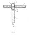
- eine Seitenansicht der Pedikelschraube,
- Fig. 3
- der Schnitt III-III aus Fig. 2,
- Fig. 4
- eine Draufsicht auf die Pedikelschraube ausFig. 2,
- Fig. 5
- eine Seitenansicht des Gewindeschaftes mit demKopfteil,
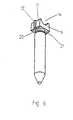
- Fig. 6
- eine perspektivische Darstellung der auf dasRundstück aufgesetzten Kappe,
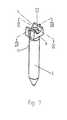
- Fig. 7
- eine weitere perspektivische Darstellung derPedikelschraube aus Fig. 6 aus einem anderenBlickwinkel,
- Fig. 8
- der Schnitt VIII-VIII aus Fig. 7,
- Fig. 9
- der Schnitt IX-IX aus Fig. 7
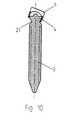
- Fig. 10
- eine der Fig. 9 entsprechende Darstellung miteiner gegenüber Fig. 9 verdrehten Kappe, und
- Fig. 11
- eine perspektivischen Darstellung des U-förmigenBügelteils.
- Fig. 1
- 2 shows a perspective view of the pedicle screw according to the invention with a rod fixed to the head part,
- Fig. 2
- a side view of the pedicle screw,
- Fig. 3
- the section III-III of Fig. 2,
- Fig. 4
- 3 shows a plan view of the pedicle screw from FIG. 2,
- Fig. 5
- a side view of the threaded shaft with the head part,
- Fig. 6
- a perspective view of the cap placed on the round piece,
- Fig. 7
- 6 shows another perspective view of the pedicle screw from FIG. 6 from a different point of view,
- Fig. 8
- the section VIII-VIII of Fig. 7,
- Fig. 9
- the section IX-IX from FIG. 7
- Fig. 10
- 9 shows a representation corresponding to FIG. 9 with a cap rotated relative to FIG. 9, and
- Fig. 11
- a perspective view of the U-shaped bracket part.
Die in der Fig. 1 dargestellte Pedikelschraube 1 wirdbenutzt im Zusammenhang mit Implantaten, die der Korrekturund Stabilisierung der Wirbelsäule dienen und die dazueinen an der Wirbelsäule entlanggeführten Stab 2verwenden. Die Pedikelschraube 1 besteht aus einemGewindeschaft 3, an dessen einem axialen Ende ein durchein Rundstück 4 und eine Kappe 6 gebildetes Kopfteil 5angeordnet ist. Dabei ist das Rundstück 4 als Halbkugel 20ausgebildet, deren Planfläche 22 senkrecht zu demGewindeschaft 3 orientiert ist und nach außen weist. Aufder Planfläche 22 der Halbkugel 20 ist eine Kalotte 23angeordnet, deren Durchmesser kleiner als der derHalbkugel 20 ist. Aus diesem Aufbau ergibt sich, daß dieKappe 6 polyaxial um das Rundstück 4 verdrehbar und einegute Anpassungsmöglichkeit an die Lage des an derWirbelsäule entlanggeführten Stabes 2 gegeben ist (Fig. 3,8,10).The
Die auf dem Rundstück 4 angeordnete Kappe 6 wird von einemU-förmigen Bügelteil 7 übergriffen, das eine Aufnahme fürden Stab 2 bereitstellt. Das Bügelteil 7 besteht aus einerGrundplatte 8 und zwei Seitenschenkeln 9, an deren freienEnden Rastnasen 10 ausgebildet sind. Zur Fixierung desBügelteils 7 wird dieses durch eine ausschließlich inaxialer Richtung erfolgende Steckbewegung auf die Kappe 6aufgesteckt, wobei die Rastnasen 10 an den Kanten von derKappe 6 zugeordneten Endplatten 11 in einem Rastsitzeinhaken. Um eine lagerichtige Verbindung des Bügelteils 7mit der Kappe 6 zu gewährleisten, sowie um ein Verschiebendes Bügelteiles 7 in Längsrichtung des Stabes 2 zuvermeiden, sind an den Endplatten 11 Führungsstege 12ausgebildet, die mit einer Führungsnut 13 zusammenwirken,die an den Seitenschenkeln 9 des Bügelteils 7 ausgebildetsind. Nach einer selber nicht in der Zeichnungdargestellten Ausführungsform ist es selbstverständlichauch möglich, daß die Führungsstege 12 und dieFührungsnuten 13 an den Endplatten 11 und denSeitenschenkeln 9 miteinander vertauscht sind.The arranged on the
Eine in der Grundplatte 8 des Bügelteils 7 angeordneteGewindebohrung 18 dient zur Aufnahme einerSicherungsschraube 19, mit der der Stab 2 gegenVerschiebungen in seiner Längsrichtung gesichert werdenkann. Diese Sicherungsschraube 19 verspannt imZusammenwirken mit den Rastnasen 10 auch das Bügelteil 7gegenüber der Kappe 6, was weiterhin dazu ausgenutzt wird,um die Kappe 6 gegen die Halbkugel 20 zu pressen. Wennnach einer Ausführungsform die einander zugewandtenOberflächen von dem Rundstück 4 und der Kappe 6 eine Oberflächenprofilierung aufweisen, wirkt dies als Mittelzur Blockade der Drehbarkeit von der Kappe 6 und demRundstück 4, wobei die Gestaltung derOberflächenprofilierung die Möglichkeit offenläßt, dieDrehbarkeit vollständig, hinsichtlich mehrerer Achsen odernur hinsichtlich einer Achse zu unterbinden.One arranged in the base plate 8 of the
Wie insbesondere aus Fig. 7 ersichtlich ist, weist dieKappe 6 eine Rinne 14 als Auflager für den Stab 2 auf. DieUmfassung des Stabes 2 durch die Pedikelschraube 1 wirddurch eine in der Grundplatte 8 des Bügelteils 7ausgebildete Rinne 16 komplettiert.As can be seen in particular from FIG. 7, theCap 6 a channel 14 as a support for the
Aus den Fig. 1, 3 und 11 ist ersichtlich, daß amBügelteil 7 zwischen der Grundplatte 8 und denSeitenschenkeln 9 eine Nut 17 ausgebildet ist, die dasAufspreizen des Bügelteil 7 beim Aufsteckvorgangerleichtert. Ein unerwünschtes Aufspreizen nach demAufstecken des Bügelteils 7 wird dadurch verhindert, daßdie Rastnasen 10 die freien Kanten der Endplatten 11hintergreifen.1, 3 and 11 it can be seen that on
Aus der Zeichnung, insbesondere den Fig. 5 bis 10 istweiterhin ersichtlich, daß das Kopfteil 5 an einerVerjüngung 21 des Gewindeschaftes 3 angesetzt ist, derDrehwinkel der Kappe 6 also nicht frühzeitig durch dessenAnlage an dem Gewindeschaft 3 begrenzt ist.From the drawing, in particular FIGS. 5 to 10can also be seen that the head part 5 on a
Claims (14)
- A pedicle screw for implants for correction and stabilisation of thespinal column, comprising a head portion (5) which is arranged at the axialend of a screwthreaded shank (3) and a stirrup portion (7) which can beconnected to the head portion and which is of a U-shaped configurationwith a base plate (8) and two side limbs (9) and has a receiving means fora rod (2) which can be fixed to the head portion (5), wherein the headportion (5) has a round part (4)characterised in that the head portion (5)further has a polyaxially rotatable cap (6) which is mounted rotatably onthe round part (4) and that the stirrup portion (7) can be fixed in aretaining fit on the cap (6) by a plug-in movement in the axial direction.
- A pedicle screw according to claim 1characterised in that theround part (4) is in the form of a hemispherical portion (20) with a flatsurface (22) which is oriented in perpendicular relationship to thescrewthreaded shank (3) and which faces towards the free end.
- A pedicle screw according to claim 2characterised in thatarranged on the flat surface (22) is a part-spherical portion (23) of asmaller diameter than the hemispherical portion (20).
- A pedicle screw according to one of claims 1 to 3characterised inthat provided at the free ends of the side limbs (9) are retaining noses (10)which come into hooking engagement on the cap (6) to provide theretaining fit in the plug-in movement.
- A pedicle screw according to one of claims 1 to 4characterised inthat there are provided means for blocking the rotatability of the cap (6) onthe round part (4).
- A pedicle screw according to claim 5characterised in that themutually facing surfaces of the round part (4) and the cap (6) have asurface profiling and that provided in the base plate (8) of the stirrupportion (7) is a screwthreaded bore (18) for a securing screw (19) whichserves to fix the rod (2).
- A pedicle screw according to one of claims 1 to 6characterised inthat arranged on the cap (6) are end plates (11) each having a respectiveguide leg (12) extending in the axial direction and that each side limb (9)has a guide groove (13) for the guide leg (12).
- A pedicle screw according to claim 7characterised in that theguide legs (12) and the guide grooves (13) on the end plates (11) and theside limbs (9) are interchanged with each other.
- A pedicle screw according to one of claims 4 to 8characterised inthat the retaining noses (10) engage behind the free edges of the endplates (11).
- A pedicle screw according to one of claims 1 to 9characterised inthat the cap (6) has a channel (14) as a support for the rod (2).
- A pedicle screw according to claim 10characterised in that anopening (15) is provided in the channel (14).
- A pedicle screw according to one of claims 4 to 11characterisedin that a channel (16) is provided in the base plate (8) of the stirrup portion(7).
- A pedicle screw according to one of claims 2 to 12characterisedin that a groove (17) is provided between the base plate (8) and the sidelimbs (9).
- A pedicle screw according to one of claims 1 to 13characterisedin that the head portion (5) is attached to a constriction (21) of thescrewthreaded shank (3).
Applications Claiming Priority (2)
| Application Number | Priority Date | Filing Date | Title |
|---|---|---|---|
| DE10005385ADE10005385A1 (en) | 2000-02-07 | 2000-02-07 | Pedicle screw |
| DE10005385 | 2000-02-07 |
Publications (3)
| Publication Number | Publication Date |
|---|---|
| EP1121902A2 EP1121902A2 (en) | 2001-08-08 |
| EP1121902A3 EP1121902A3 (en) | 2002-02-06 |
| EP1121902B1true EP1121902B1 (en) | 2004-09-22 |
Family
ID=7630128
Family Applications (1)
| Application Number | Title | Priority Date | Filing Date |
|---|---|---|---|
| EP01100933AExpired - LifetimeEP1121902B1 (en) | 2000-02-07 | 2001-01-17 | Pedicle screw |
Country Status (5)
| Country | Link |
|---|---|
| US (1) | US6402752B2 (en) |
| EP (1) | EP1121902B1 (en) |
| AT (1) | ATE276705T1 (en) |
| DE (2) | DE10005385A1 (en) |
| ES (1) | ES2223651T3 (en) |
Cited By (57)
| Publication number | Priority date | Publication date | Assignee | Title |
|---|---|---|---|---|
| US7377923B2 (en) | 2003-05-22 | 2008-05-27 | Alphatec Spine, Inc. | Variable angle spinal screw assembly |
| US7476239B2 (en) | 2005-05-10 | 2009-01-13 | Jackson Roger P | Polyaxial bone screw with compound articulation |
| US7662175B2 (en) | 2003-06-18 | 2010-02-16 | Jackson Roger P | Upload shank swivel head bone screw spinal implant |
| US7766915B2 (en) | 2004-02-27 | 2010-08-03 | Jackson Roger P | Dynamic fixation assemblies with inner core and outer coil-like member |
| US7875065B2 (en) | 2004-11-23 | 2011-01-25 | Jackson Roger P | Polyaxial bone screw with multi-part shank retainer and pressure insert |
| US7901437B2 (en) | 2007-01-26 | 2011-03-08 | Jackson Roger P | Dynamic stabilization member with molded connection |
| US7942911B2 (en) | 2007-05-16 | 2011-05-17 | Ortho Innovations, Llc | Polyaxial bone screw |
| US7942909B2 (en) | 2009-08-13 | 2011-05-17 | Ortho Innovations, Llc | Thread-thru polyaxial pedicle screw system |
| US7942910B2 (en) | 2007-05-16 | 2011-05-17 | Ortho Innovations, Llc | Polyaxial bone screw |
| US7947065B2 (en) | 2008-11-14 | 2011-05-24 | Ortho Innovations, Llc | Locking polyaxial ball and socket fastener |
| US7951170B2 (en) | 2007-05-31 | 2011-05-31 | Jackson Roger P | Dynamic stabilization connecting member with pre-tensioned solid core |
| US7951173B2 (en) | 2007-05-16 | 2011-05-31 | Ortho Innovations, Llc | Pedicle screw implant system |
| US7967850B2 (en) | 2003-06-18 | 2011-06-28 | Jackson Roger P | Polyaxial bone anchor with helical capture connection, insert and dual locking assembly |
| US8012177B2 (en) | 2007-02-12 | 2011-09-06 | Jackson Roger P | Dynamic stabilization assembly with frusto-conical connection |
| US8066739B2 (en) | 2004-02-27 | 2011-11-29 | Jackson Roger P | Tool system for dynamic spinal implants |
| US8075603B2 (en) | 2008-11-14 | 2011-12-13 | Ortho Innovations, Llc | Locking polyaxial ball and socket fastener |
| US8092502B2 (en) | 2003-04-09 | 2012-01-10 | Jackson Roger P | Polyaxial bone screw with uploaded threaded shank and method of assembly and use |
| US8092500B2 (en) | 2007-05-01 | 2012-01-10 | Jackson Roger P | Dynamic stabilization connecting member with floating core, compression spacer and over-mold |
| US8100915B2 (en) | 2004-02-27 | 2012-01-24 | Jackson Roger P | Orthopedic implant rod reduction tool set and method |
| US8105368B2 (en) | 2005-09-30 | 2012-01-31 | Jackson Roger P | Dynamic stabilization connecting member with slitted core and outer sleeve |
| US8128667B2 (en) | 2002-09-06 | 2012-03-06 | Jackson Roger P | Anti-splay medical implant closure with multi-surface removal aperture |
| US8197518B2 (en) | 2007-05-16 | 2012-06-12 | Ortho Innovations, Llc | Thread-thru polyaxial pedicle screw system |
| US8257398B2 (en) | 2003-06-18 | 2012-09-04 | Jackson Roger P | Polyaxial bone screw with cam capture |
| US8257402B2 (en) | 2002-09-06 | 2012-09-04 | Jackson Roger P | Closure for rod receiving orthopedic implant having left handed thread removal |
| US8273089B2 (en) | 2004-11-23 | 2012-09-25 | Jackson Roger P | Spinal fixation tool set and method |
| US8273109B2 (en) | 2002-09-06 | 2012-09-25 | Jackson Roger P | Helical wound mechanically interlocking mating guide and advancement structure |
| US8292926B2 (en) | 2005-09-30 | 2012-10-23 | Jackson Roger P | Dynamic stabilization connecting member with elastic core and outer sleeve |
| US8308782B2 (en) | 2004-11-23 | 2012-11-13 | Jackson Roger P | Bone anchors with longitudinal connecting member engaging inserts and closures for fixation and optional angulation |
| US8353932B2 (en) | 2005-09-30 | 2013-01-15 | Jackson Roger P | Polyaxial bone anchor assembly with one-piece closure, pressure insert and plastic elongate member |
| US8366753B2 (en) | 2003-06-18 | 2013-02-05 | Jackson Roger P | Polyaxial bone screw assembly with fixed retaining structure |
| US8366745B2 (en) | 2007-05-01 | 2013-02-05 | Jackson Roger P | Dynamic stabilization assembly having pre-compressed spacers with differential displacements |
| US8377100B2 (en) | 2000-12-08 | 2013-02-19 | Roger P. Jackson | Closure for open-headed medical implant |
| US8377102B2 (en) | 2003-06-18 | 2013-02-19 | Roger P. Jackson | Polyaxial bone anchor with spline capture connection and lower pressure insert |
| US8398682B2 (en) | 2003-06-18 | 2013-03-19 | Roger P. Jackson | Polyaxial bone screw assembly |
| US8444681B2 (en) | 2009-06-15 | 2013-05-21 | Roger P. Jackson | Polyaxial bone anchor with pop-on shank, friction fit retainer and winged insert |
| US8475498B2 (en) | 2007-01-18 | 2013-07-02 | Roger P. Jackson | Dynamic stabilization connecting member with cord connection |
| US8556938B2 (en) | 2009-06-15 | 2013-10-15 | Roger P. Jackson | Polyaxial bone anchor with non-pivotable retainer and pop-on shank, some with friction fit |
| US8591515B2 (en) | 2004-11-23 | 2013-11-26 | Roger P. Jackson | Spinal fixation tool set and method |
| US8814913B2 (en) | 2002-09-06 | 2014-08-26 | Roger P Jackson | Helical guide and advancement flange with break-off extensions |
| US8814911B2 (en) | 2003-06-18 | 2014-08-26 | Roger P. Jackson | Polyaxial bone screw with cam connection and lock and release insert |
| US8845649B2 (en) | 2004-09-24 | 2014-09-30 | Roger P. Jackson | Spinal fixation tool set and method for rod reduction and fastener insertion |
| US8876868B2 (en) | 2002-09-06 | 2014-11-04 | Roger P. Jackson | Helical guide and advancement flange with radially loaded lip |
| US8911479B2 (en) | 2012-01-10 | 2014-12-16 | Roger P. Jackson | Multi-start closures for open implants |
| US8911477B2 (en) | 2007-10-23 | 2014-12-16 | Roger P. Jackson | Dynamic stabilization member with end plate support and cable core extension |
| US8936623B2 (en) | 2003-06-18 | 2015-01-20 | Roger P. Jackson | Polyaxial bone screw assembly |
| US8979904B2 (en) | 2007-05-01 | 2015-03-17 | Roger P Jackson | Connecting member with tensioned cord, low profile rigid sleeve and spacer with torsion control |
| US8998959B2 (en) | 2009-06-15 | 2015-04-07 | Roger P Jackson | Polyaxial bone anchors with pop-on shank, fully constrained friction fit retainer and lock and release insert |
| US9050139B2 (en) | 2004-02-27 | 2015-06-09 | Roger P. Jackson | Orthopedic implant rod reduction tool set and method |
| US9168069B2 (en) | 2009-06-15 | 2015-10-27 | Roger P. Jackson | Polyaxial bone anchor with pop-on shank and winged insert with lower skirt for engaging a friction fit retainer |
| US9198695B2 (en) | 2010-08-30 | 2015-12-01 | Zimmer Spine, Inc. | Polyaxial pedicle screw |
| US9216041B2 (en) | 2009-06-15 | 2015-12-22 | Roger P. Jackson | Spinal connecting members with tensioned cords and rigid sleeves for engaging compression inserts |
| US9216039B2 (en) | 2004-02-27 | 2015-12-22 | Roger P. Jackson | Dynamic spinal stabilization assemblies, tool set and method |
| US9414863B2 (en) | 2005-02-22 | 2016-08-16 | Roger P. Jackson | Polyaxial bone screw with spherical capture, compression insert and alignment and retention structures |
| US9451989B2 (en) | 2007-01-18 | 2016-09-27 | Roger P Jackson | Dynamic stabilization members with elastic and inelastic sections |
| US9453526B2 (en) | 2013-04-30 | 2016-09-27 | Degen Medical, Inc. | Bottom-loading anchor assembly |
| US9456853B2 (en) | 2005-05-27 | 2016-10-04 | Roger P. Jackson | Polyaxial bone screw with shank articulation pressure insert and method |
| US9480517B2 (en) | 2009-06-15 | 2016-11-01 | Roger P. Jackson | Polyaxial bone anchor with pop-on shank, shank, friction fit retainer, winged insert and low profile edge lock |
Families Citing this family (200)
| Publication number | Priority date | Publication date | Assignee | Title |
|---|---|---|---|---|
| US7833250B2 (en) | 2004-11-10 | 2010-11-16 | Jackson Roger P | Polyaxial bone screw with helically wound capture connection |
| US20050025916A1 (en)* | 2000-11-30 | 2005-02-03 | Hideki Nakanishi | Transfer sheet |
| US6451021B1 (en)* | 2001-02-15 | 2002-09-17 | Third Millennium Engineering, Llc | Polyaxial pedicle screw having a rotating locking element |
| FR2822053B1 (en) | 2001-03-15 | 2003-06-20 | Stryker Spine Sa | ANCHORING MEMBER WITH SAFETY RING FOR SPINAL OSTEOSYNTHESIS SYSTEM |
| US10258382B2 (en) | 2007-01-18 | 2019-04-16 | Roger P. Jackson | Rod-cord dynamic connection assemblies with slidable bone anchor attachment members along the cord |
| US10729469B2 (en) | 2006-01-09 | 2020-08-04 | Roger P. Jackson | Flexible spinal stabilization assembly with spacer having off-axis core member |
| GB2393189B (en)* | 2001-07-19 | 2005-06-15 | Trikon Holdings Ltd | Depositing a tantalum film |
| CN1268294C (en)* | 2001-11-22 | 2006-08-09 | 库尔斯恩蒂斯股份公司 | Device for joining a longitudinal support with a bone fixation means |
| JP4130411B2 (en)* | 2002-02-11 | 2008-08-06 | ジンテーズ ゲゼルシャフト ミト ベシュレンクテル ハフツング | Device for joining the vertical support and bone |
| US7066937B2 (en)* | 2002-02-13 | 2006-06-27 | Endius Incorporated | Apparatus for connecting a longitudinal member to a bone portion |
| US7879075B2 (en) | 2002-02-13 | 2011-02-01 | Zimmer Spine, Inc. | Methods for connecting a longitudinal member to a bone portion |
| WO2003086204A2 (en)* | 2002-04-09 | 2003-10-23 | Neville Alleyne | Bone fixation apparatus |
| DE20207851U1 (en) | 2002-05-21 | 2002-10-10 | Metz-Stavenhagen, Peter, Dr.med., 34537 Bad Wildungen | Anchoring element for fastening a rod of a device for setting up a human or animal spine to a vertebral bone |
| FR2844180B1 (en)* | 2002-09-11 | 2005-08-05 | Spinevision | CONNECTING ELEMENT FOR THE DYNAMIC STABILIZATION OF A SPINAL FIXING SYSTEM AND SPINAL FASTENING SYSTEM COMPRISING SUCH A MEMBER |
| US20040073221A1 (en)* | 2002-10-11 | 2004-04-15 | Spineco, Inc., A Corporation Of Ohio | Electro-stimulation and medical delivery device |
| US7615070B2 (en)* | 2002-10-11 | 2009-11-10 | Spineco, Inc. | Electro-stimulation and medical delivery device |
| US7476228B2 (en)* | 2002-10-11 | 2009-01-13 | Abdou M Samy | Distraction screw for skeletal surgery and method of use |
| WO2004062482A2 (en)* | 2003-01-10 | 2004-07-29 | Abdou Samy M | Plating system for bone fixation and subsidence and method of implantation |
| US7887539B2 (en) | 2003-01-24 | 2011-02-15 | Depuy Spine, Inc. | Spinal rod approximators |
| US7141051B2 (en) | 2003-02-05 | 2006-11-28 | Pioneer Laboratories, Inc. | Low profile spinal fixation system |
| US6964666B2 (en)* | 2003-04-09 | 2005-11-15 | Jackson Roger P | Polyaxial bone screw locking mechanism |
| US8137386B2 (en) | 2003-08-28 | 2012-03-20 | Jackson Roger P | Polyaxial bone screw apparatus |
| US7322981B2 (en) | 2003-08-28 | 2008-01-29 | Jackson Roger P | Polyaxial bone screw with split retainer ring |
| JP4357486B2 (en) | 2003-06-18 | 2009-11-04 | ロジャー・ピー・ジャクソン | Polyaxial bone screw with spline capture connection |
| US7087057B2 (en) | 2003-06-27 | 2006-08-08 | Depuy Acromed, Inc. | Polyaxial bone screw |
| US6945975B2 (en)* | 2003-07-07 | 2005-09-20 | Aesculap, Inc. | Bone fixation assembly and method of securement |
| US6945974B2 (en) | 2003-07-07 | 2005-09-20 | Aesculap Inc. | Spinal stabilization implant and method of application |
| ATE407634T1 (en)* | 2003-09-08 | 2008-09-15 | Synthes Gmbh | LONGITUDINAL BEAM |
| US8070785B2 (en) | 2003-09-16 | 2011-12-06 | Spineco, Inc. | Bone anchor prosthesis and system |
| US11419642B2 (en) | 2003-12-16 | 2022-08-23 | Medos International Sarl | Percutaneous access devices and bone anchor assemblies |
| US7179261B2 (en) | 2003-12-16 | 2007-02-20 | Depuy Spine, Inc. | Percutaneous access devices and bone anchor assemblies |
| US7527638B2 (en) | 2003-12-16 | 2009-05-05 | Depuy Spine, Inc. | Methods and devices for minimally invasive spinal fixation element placement |
| US7635366B2 (en)* | 2003-12-29 | 2009-12-22 | Abdou M Samy | Plating system for bone fixation and method of implantation |
| US7993373B2 (en) | 2005-02-22 | 2011-08-09 | Hoy Robert W | Polyaxial orthopedic fastening apparatus |
| US7311712B2 (en)* | 2004-02-26 | 2007-12-25 | Aesculap Implant Systems, Inc. | Polyaxial locking screw plate assembly |
| US7789896B2 (en) | 2005-02-22 | 2010-09-07 | Jackson Roger P | Polyaxial bone screw assembly |
| EP1758511A4 (en)* | 2004-06-14 | 2008-12-03 | M S Abdou | Occipital fixation system and method of use |
| US7303563B2 (en)* | 2004-06-17 | 2007-12-04 | Sdgi Holdings, Inc. | Orthopedic fixation system and method of use |
| US8114158B2 (en) | 2004-08-03 | 2012-02-14 | Kspine, Inc. | Facet device and method |
| US7766945B2 (en)* | 2004-08-10 | 2010-08-03 | Lanx, Inc. | Screw and rod fixation system |
| US7186255B2 (en)* | 2004-08-12 | 2007-03-06 | Atlas Spine, Inc. | Polyaxial screw |
| DE202004020396U1 (en) | 2004-08-12 | 2005-07-07 | Columbus Trading-Partners Pos und Brendel GbR (vertretungsberechtigte Gesellschafter Karin Brendel, 95503 Hummeltal und Bohumila Pos, 95445 Bayreuth) | Child seat for motor vehicles |
| CA2580101A1 (en) | 2004-09-14 | 2006-03-23 | Spineco, Inc. | Implant device |
| WO2006047711A2 (en) | 2004-10-25 | 2006-05-04 | Alphaspine, Inc. | Pedicle screw systems and methods |
| US7604655B2 (en) | 2004-10-25 | 2009-10-20 | X-Spine Systems, Inc. | Bone fixation system and method for using the same |
| US7513905B2 (en) | 2004-11-03 | 2009-04-07 | Jackson Roger P | Polyaxial bone screw |
| US8926672B2 (en) | 2004-11-10 | 2015-01-06 | Roger P. Jackson | Splay control closure for open bone anchor |
| US7572279B2 (en) | 2004-11-10 | 2009-08-11 | Jackson Roger P | Polyaxial bone screw with discontinuous helically wound capture connection |
| US9980753B2 (en) | 2009-06-15 | 2018-05-29 | Roger P Jackson | pivotal anchor with snap-in-place insert having rotation blocking extensions |
| ATE536821T1 (en) | 2004-11-23 | 2011-12-15 | Roger P Jackson | POLYAXIAL BONE SCREW WITH MULTIPLE SHAFT FIXATION |
| WO2006057837A1 (en) | 2004-11-23 | 2006-06-01 | Jackson Roger P | Spinal fixation tool attachment structure |
| WO2006058221A2 (en) | 2004-11-24 | 2006-06-01 | Abdou Samy M | Devices and methods for inter-vertebral orthopedic device placement |
| US7736380B2 (en) | 2004-12-21 | 2010-06-15 | Rhausler, Inc. | Cervical plate system |
| US7445627B2 (en)* | 2005-01-31 | 2008-11-04 | Alpinespine, Llc | Polyaxial pedicle screw assembly |
| AU2006214001B2 (en) | 2005-02-18 | 2011-05-26 | Samy Abdou | Devices and methods for dynamic fixation of skeletal structure |
| US7951175B2 (en) | 2005-03-04 | 2011-05-31 | Depuy Spine, Inc. | Instruments and methods for manipulating a vertebra |
| US7951172B2 (en) | 2005-03-04 | 2011-05-31 | Depuy Spine Sarl | Constrained motion bone screw assembly |
| WO2006096756A2 (en)* | 2005-03-07 | 2006-09-14 | Abdou M Samy | Occipital fixation system |
| TWI375545B (en) | 2005-04-25 | 2012-11-01 | Synthes Gmbh | Bone anchor with locking cap and method of spinal fixation |
| US7883532B2 (en)* | 2005-04-25 | 2011-02-08 | Spineco, Inc. | Vertebral pars interarticularis clamp a new spine fixation device, instrumentation, and methodology |
| WO2006127992A2 (en)* | 2005-05-25 | 2006-11-30 | Alphaspine, Inc. | Low profile pedicle screw and rod assembly |
| WO2008137933A1 (en)* | 2005-05-25 | 2008-11-13 | Alpinespine Llc | Low rider pedicle screw system |
| US7766946B2 (en)* | 2005-07-27 | 2010-08-03 | Frank Emile Bailly | Device for securing spinal rods |
| US7717943B2 (en)* | 2005-07-29 | 2010-05-18 | X-Spine Systems, Inc. | Capless multiaxial screw and spinal fixation assembly and method |
| WO2007041648A2 (en)* | 2005-10-03 | 2007-04-12 | Abdou Samy M | Devices and methods for inter-vertebral orthopedic device placement |
| WO2007041702A2 (en) | 2005-10-04 | 2007-04-12 | Alphaspine, Inc. | Pedicle screw system with provisional locking aspects |
| US7927359B2 (en)* | 2005-10-06 | 2011-04-19 | Paradigm Spine, Llc | Polyaxial screw |
| US8870920B2 (en)* | 2005-10-07 | 2014-10-28 | M. Samy Abdou | Devices and methods for inter-vertebral orthopedic device placement |
| US8002806B2 (en)* | 2005-10-20 | 2011-08-23 | Warsaw Orthopedic, Inc. | Bottom loading multi-axial screw assembly |
| US7722651B2 (en) | 2005-10-21 | 2010-05-25 | Depuy Spine, Inc. | Adjustable bone screw assembly |
| GB0521582D0 (en) | 2005-10-22 | 2005-11-30 | Depuy Int Ltd | An implant for supporting a spinal column |
| US8097025B2 (en) | 2005-10-25 | 2012-01-17 | X-Spine Systems, Inc. | Pedicle screw system configured to receive a straight or curved rod |
| US8100946B2 (en) | 2005-11-21 | 2012-01-24 | Synthes Usa, Llc | Polyaxial bone anchors with increased angulation |
| US20070161986A1 (en)* | 2005-12-13 | 2007-07-12 | Levy Mark M | Polyaxial fastener assembly |
| US7704271B2 (en) | 2005-12-19 | 2010-04-27 | Abdou M Samy | Devices and methods for inter-vertebral orthopedic device placement |
| KR200410476Y1 (en)* | 2005-12-21 | 2006-03-07 | (주)베리안 | Pedicle screw |
| US20070173819A1 (en)* | 2006-01-11 | 2007-07-26 | Robin Sandlin | Spinal implant fixation assembly |
| GB0600662D0 (en) | 2006-01-13 | 2006-02-22 | Depuy Int Ltd | Spinal support rod kit |
| US8348952B2 (en) | 2006-01-26 | 2013-01-08 | Depuy International Ltd. | System and method for cooling a spinal correction device comprising a shape memory material for corrective spinal surgery |
| CA2647026A1 (en)* | 2006-03-22 | 2008-08-28 | Pioneer Surgical Technology, Inc. | Low top bone fixation system and method for using the same |
| US8361129B2 (en) | 2006-04-28 | 2013-01-29 | Depuy Spine, Inc. | Large diameter bone anchor assembly |
| US8133262B2 (en)* | 2006-04-28 | 2012-03-13 | Depuy Spine, Inc. | Large diameter bone anchor assembly |
| US20080058808A1 (en) | 2006-06-14 | 2008-03-06 | Spartek Medical, Inc. | Implant system and method to treat degenerative disorders of the spine |
| US7922748B2 (en)* | 2006-06-16 | 2011-04-12 | Zimmer Spine, Inc. | Removable polyaxial housing for a pedicle screw |
| US8303630B2 (en)* | 2006-07-27 | 2012-11-06 | Samy Abdou | Devices and methods for the minimally invasive treatment of spinal stenosis |
| US8062340B2 (en)* | 2006-08-16 | 2011-11-22 | Pioneer Surgical Technology, Inc. | Spinal rod anchor device and method |
| WO2008024373A2 (en)* | 2006-08-21 | 2008-02-28 | Abdou M Samy | Bone screw systems and methods of use |
| US8414628B2 (en) | 2006-10-26 | 2013-04-09 | Warsaw Orthopedic, Inc. | Bone screw |
| US8162990B2 (en)* | 2006-11-16 | 2012-04-24 | Spine Wave, Inc. | Multi-axial spinal fixation system |
| US8926667B2 (en)* | 2007-02-09 | 2015-01-06 | Transcendental Spine, Llc | Connector |
| US8167912B2 (en) | 2007-02-27 | 2012-05-01 | The Center for Orthopedic Research and Education, Inc | Modular pedicle screw system |
| US8926669B2 (en)* | 2007-02-27 | 2015-01-06 | The Center For Orthopedic Research And Education, Inc. | Modular polyaxial pedicle screw system |
| US8202302B2 (en)* | 2007-04-19 | 2012-06-19 | Mi4Spine, Llc | Pedicle screw and rod system |
| US7922725B2 (en)* | 2007-04-19 | 2011-04-12 | Zimmer Spine, Inc. | Method and associated instrumentation for installation of spinal dynamic stabilization system |
| US10383660B2 (en) | 2007-05-01 | 2019-08-20 | Roger P. Jackson | Soft stabilization assemblies with pretensioned cords |
| US8048115B2 (en) | 2007-06-05 | 2011-11-01 | Spartek Medical, Inc. | Surgical tool and method for implantation of a dynamic bone anchor |
| US8048128B2 (en) | 2007-06-05 | 2011-11-01 | Spartek Medical, Inc. | Revision system and method for a dynamic stabilization and motion preservation spinal implantation system and method |
| US8083772B2 (en) | 2007-06-05 | 2011-12-27 | Spartek Medical, Inc. | Dynamic spinal rod assembly and method for dynamic stabilization of the spine |
| US8109970B2 (en) | 2007-06-05 | 2012-02-07 | Spartek Medical, Inc. | Deflection rod system with a deflection contouring shield for a spine implant and method |
| US8092501B2 (en) | 2007-06-05 | 2012-01-10 | Spartek Medical, Inc. | Dynamic spinal rod and method for dynamic stabilization of the spine |
| US8052722B2 (en) | 2007-06-05 | 2011-11-08 | Spartek Medical, Inc. | Dual deflection rod system for a dynamic stabilization and motion preservation spinal implantation system and method |
| US8114134B2 (en) | 2007-06-05 | 2012-02-14 | Spartek Medical, Inc. | Spinal prosthesis having a three bar linkage for motion preservation and dynamic stabilization of the spine |
| US8048123B2 (en) | 2007-06-05 | 2011-11-01 | Spartek Medical, Inc. | Spine implant with a deflection rod system and connecting linkages and method |
| US8021396B2 (en) | 2007-06-05 | 2011-09-20 | Spartek Medical, Inc. | Configurable dynamic spinal rod and method for dynamic stabilization of the spine |
| EP2155086B1 (en) | 2007-06-06 | 2016-05-04 | K2M, Inc. | Medical device to correct deformity |
| US9439681B2 (en) | 2007-07-20 | 2016-09-13 | DePuy Synthes Products, Inc. | Polyaxial bone fixation element |
| PL2170192T3 (en)* | 2007-07-20 | 2011-07-29 | Synthes Gmbh | Polyaxial bone fixation element |
| US20090105756A1 (en)* | 2007-10-23 | 2009-04-23 | Marc Richelsoph | Spinal implant |
| US8398683B2 (en)* | 2007-10-23 | 2013-03-19 | Pioneer Surgical Technology, Inc. | Rod coupling assembly and methods for bone fixation |
| GB0720762D0 (en) | 2007-10-24 | 2007-12-05 | Depuy Spine Sorl | Assembly for orthopaedic surgery |
| US9232968B2 (en) | 2007-12-19 | 2016-01-12 | DePuy Synthes Products, Inc. | Polymeric pedicle rods and methods of manufacturing |
| US9277940B2 (en) | 2008-02-05 | 2016-03-08 | Zimmer Spine, Inc. | System and method for insertion of flexible spinal stabilization element |
| US8007518B2 (en) | 2008-02-26 | 2011-08-30 | Spartek Medical, Inc. | Load-sharing component having a deflectable post and method for dynamic stabilization of the spine |
| US8083775B2 (en) | 2008-02-26 | 2011-12-27 | Spartek Medical, Inc. | Load-sharing bone anchor having a natural center of rotation and method for dynamic stabilization of the spine |
| US8337536B2 (en) | 2008-02-26 | 2012-12-25 | Spartek Medical, Inc. | Load-sharing bone anchor having a deflectable post with a compliant ring and method for stabilization of the spine |
| US8048125B2 (en) | 2008-02-26 | 2011-11-01 | Spartek Medical, Inc. | Versatile offset polyaxial connector and method for dynamic stabilization of the spine |
| US8267979B2 (en) | 2008-02-26 | 2012-09-18 | Spartek Medical, Inc. | Load-sharing bone anchor having a deflectable post and axial spring and method for dynamic stabilization of the spine |
| US8097024B2 (en) | 2008-02-26 | 2012-01-17 | Spartek Medical, Inc. | Load-sharing bone anchor having a deflectable post and method for stabilization of the spine |
| US8057517B2 (en) | 2008-02-26 | 2011-11-15 | Spartek Medical, Inc. | Load-sharing component having a deflectable post and centering spring and method for dynamic stabilization of the spine |
| US8211155B2 (en) | 2008-02-26 | 2012-07-03 | Spartek Medical, Inc. | Load-sharing bone anchor having a durable compliant member and method for dynamic stabilization of the spine |
| US8333792B2 (en) | 2008-02-26 | 2012-12-18 | Spartek Medical, Inc. | Load-sharing bone anchor having a deflectable post and method for dynamic stabilization of the spine |
| US8709015B2 (en) | 2008-03-10 | 2014-04-29 | DePuy Synthes Products, LLC | Bilateral vertebral body derotation system |
| US8608746B2 (en) | 2008-03-10 | 2013-12-17 | DePuy Synthes Products, LLC | Derotation instrument with reduction functionality |
| US8932332B2 (en)* | 2008-05-08 | 2015-01-13 | Aesculap Implant Systems, Llc | Minimally invasive spinal stabilization system |
| US10973556B2 (en) | 2008-06-17 | 2021-04-13 | DePuy Synthes Products, Inc. | Adjustable implant assembly |
| US20090326584A1 (en)* | 2008-06-27 | 2009-12-31 | Michael Andrew Slivka | Spinal Dynamic Stabilization Rods Having Interior Bumpers |
| AU2010260521C1 (en) | 2008-08-01 | 2013-08-01 | Roger P. Jackson | Longitudinal connecting member with sleeved tensioned cords |
| EP2355725B1 (en) | 2008-09-05 | 2017-03-08 | Synthes GmbH | Bone fixation assembly |
| US9603629B2 (en) | 2008-09-09 | 2017-03-28 | Intelligent Implant Systems Llc | Polyaxial screw assembly |
| JP5815407B2 (en) | 2008-09-12 | 2015-11-17 | ジンテス ゲゼルシャフト ミット ベシュレンクテル ハフツング | Spinal stabilization and guided fixation system |
| KR20110081208A (en) | 2008-09-29 | 2011-07-13 | 신세스 게엠바하 | Multi-Axis Bottom-Loading Screw and Rod Assemblies |
| US8506601B2 (en) | 2008-10-14 | 2013-08-13 | Pioneer Surgical Technology, Inc. | Low profile dual locking fixation system and offset anchor member |
| US8382809B2 (en)* | 2008-10-17 | 2013-02-26 | Omni Surgical | Poly-axial pedicle screw implements and lock screw therefor |
| US8080040B2 (en)* | 2008-10-29 | 2011-12-20 | Warsaw Orthopedic, Inc. | Anchor with two member securing mechanism for attaching an elongated member to a bone |
| US20100114168A1 (en)* | 2008-10-30 | 2010-05-06 | Warsaw Orthopedic, Inc. | Anchor with non-threaded securing mechanism to attach an elongated member to a bone |
| CA2742399A1 (en) | 2008-11-03 | 2010-06-03 | Dustin M. Harvey | Uni-planar bone fixation assembly |
| US8828058B2 (en) | 2008-11-11 | 2014-09-09 | Kspine, Inc. | Growth directed vertebral fixation system with distractible connector(s) and apical control |
| US20100160978A1 (en)* | 2008-12-23 | 2010-06-24 | John Carbone | Bone screw assembly with non-uniform material |
| US8727972B2 (en)* | 2009-02-03 | 2014-05-20 | Warsaw Orthopedic, Inc. | Low profile bone screw extender and its application in minimum invasive spinal surgeries |
| US8636778B2 (en)* | 2009-02-11 | 2014-01-28 | Pioneer Surgical Technology, Inc. | Wide angulation coupling members for bone fixation system |
| US8641734B2 (en) | 2009-02-13 | 2014-02-04 | DePuy Synthes Products, LLC | Dual spring posterior dynamic stabilization device with elongation limiting elastomers |
| US8998961B1 (en) | 2009-02-26 | 2015-04-07 | Lanx, Inc. | Spinal rod connector and methods |
| US8357182B2 (en) | 2009-03-26 | 2013-01-22 | Kspine, Inc. | Alignment system with longitudinal support features |
| KR20120013312A (en) | 2009-04-15 | 2012-02-14 | 신세스 게엠바하 | Orthodontic Connectors for Spinal Structures |
| US9668771B2 (en) | 2009-06-15 | 2017-06-06 | Roger P Jackson | Soft stabilization assemblies with off-set connector |
| US11229457B2 (en) | 2009-06-15 | 2022-01-25 | Roger P. Jackson | Pivotal bone anchor assembly with insert tool deployment |
| CA2764841A1 (en) | 2009-06-17 | 2010-12-23 | Synthes Usa, Llc | Revision connector for spinal constructs |
| US9320543B2 (en) | 2009-06-25 | 2016-04-26 | DePuy Synthes Products, Inc. | Posterior dynamic stabilization device having a mobile anchor |
| WO2011004222A1 (en)* | 2009-07-10 | 2011-01-13 | Kamil Bal | Pedicular screw system |
| KR20120051692A (en)* | 2009-07-16 | 2012-05-22 | 스파인세이브 아게 | Spinal implant set including a quick closure |
| US9168071B2 (en) | 2009-09-15 | 2015-10-27 | K2M, Inc. | Growth modulation system |
| US8361123B2 (en) | 2009-10-16 | 2013-01-29 | Depuy Spine, Inc. | Bone anchor assemblies and methods of manufacturing and use thereof |
| US20110202094A1 (en)* | 2009-11-11 | 2011-08-18 | Pereira Mario L | Trans-polyaxial screw |
| CN102695465A (en) | 2009-12-02 | 2012-09-26 | 斯帕泰克医疗股份有限公司 | Low profile spinal prosthesis incorporating a bone anchor having a deflectable post and a compound spinal rod |
| US8764806B2 (en) | 2009-12-07 | 2014-07-01 | Samy Abdou | Devices and methods for minimally invasive spinal stabilization and instrumentation |
| WO2011106339A1 (en) | 2010-02-23 | 2011-09-01 | K2M, Inc. | Polyaxial bone screw assembly |
| US9445844B2 (en) | 2010-03-24 | 2016-09-20 | DePuy Synthes Products, Inc. | Composite material posterior dynamic stabilization spring rod |
| KR100974497B1 (en) | 2010-04-27 | 2010-08-10 | 주식회사 지에스메디칼 | Bone anchoring device |
| US12383311B2 (en) | 2010-05-14 | 2025-08-12 | Roger P. Jackson | Pivotal bone anchor assembly and method for use thereof |
| US20110307015A1 (en) | 2010-06-10 | 2011-12-15 | Spartek Medical, Inc. | Adaptive spinal rod and methods for stabilization of the spine |
| AU2011324058A1 (en) | 2010-11-02 | 2013-06-20 | Roger P. Jackson | Polyaxial bone anchor with pop-on shank and pivotable retainer |
| US20120203281A1 (en)* | 2011-02-05 | 2012-08-09 | Alphatec Spine, Inc | Semi-rigid screw assembly |
| JP5865479B2 (en) | 2011-03-24 | 2016-02-17 | ロジャー・ピー・ジャクソン | Multiaxial bone anchor with compound joint and pop-mounted shank |
| JP6158176B2 (en) | 2011-06-03 | 2017-07-05 | ケイツーエム インコーポレイテッドK2M,Inc. | Spine correction system |
| US9993269B2 (en)* | 2011-07-15 | 2018-06-12 | Globus Medical, Inc. | Orthopedic fixation devices and methods of installation thereof |
| US8845728B1 (en) | 2011-09-23 | 2014-09-30 | Samy Abdou | Spinal fixation devices and methods of use |
| US8920472B2 (en) | 2011-11-16 | 2014-12-30 | Kspine, Inc. | Spinal correction and secondary stabilization |
| US9468468B2 (en) | 2011-11-16 | 2016-10-18 | K2M, Inc. | Transverse connector for spinal stabilization system |
| US9451987B2 (en) | 2011-11-16 | 2016-09-27 | K2M, Inc. | System and method for spinal correction |
| WO2014172632A2 (en) | 2011-11-16 | 2014-10-23 | Kspine, Inc. | Spinal correction and secondary stabilization |
| US9468469B2 (en) | 2011-11-16 | 2016-10-18 | K2M, Inc. | Transverse coupler adjuster spinal correction systems and methods |
| US8430916B1 (en) | 2012-02-07 | 2013-04-30 | Spartek Medical, Inc. | Spinal rod connectors, methods of use, and spinal prosthesis incorporating spinal rod connectors |
| US20130226240A1 (en) | 2012-02-22 | 2013-08-29 | Samy Abdou | Spinous process fixation devices and methods of use |
| US8491640B1 (en)* | 2012-07-02 | 2013-07-23 | James C. Robinson | Bone screw coupling assembly |
| US9198767B2 (en) | 2012-08-28 | 2015-12-01 | Samy Abdou | Devices and methods for spinal stabilization and instrumentation |
| US9320617B2 (en) | 2012-10-22 | 2016-04-26 | Cogent Spine, LLC | Devices and methods for spinal stabilization and instrumentation |
| US8911478B2 (en) | 2012-11-21 | 2014-12-16 | Roger P. Jackson | Splay control closure for open bone anchor |
| US10058354B2 (en) | 2013-01-28 | 2018-08-28 | Roger P. Jackson | Pivotal bone anchor assembly with frictional shank head seating surfaces |
| US8852239B2 (en) | 2013-02-15 | 2014-10-07 | Roger P Jackson | Sagittal angle screw with integral shank and receiver |
| US8979898B2 (en) | 2013-02-20 | 2015-03-17 | K2M, Inc. | Iliosacral polyaxial screw |
| US9468471B2 (en) | 2013-09-17 | 2016-10-18 | K2M, Inc. | Transverse coupler adjuster spinal correction systems and methods |
| US9044273B2 (en) | 2013-10-07 | 2015-06-02 | Intelligent Implant Systems, Llc | Polyaxial plate rod system and surgical procedure |
| US9566092B2 (en) | 2013-10-29 | 2017-02-14 | Roger P. Jackson | Cervical bone anchor with collet retainer and outer locking sleeve |
| US9717533B2 (en) | 2013-12-12 | 2017-08-01 | Roger P. Jackson | Bone anchor closure pivot-splay control flange form guide and advancement structure |
| US9451993B2 (en) | 2014-01-09 | 2016-09-27 | Roger P. Jackson | Bi-radial pop-on cervical bone anchor |
| US20150297266A1 (en)* | 2014-04-21 | 2015-10-22 | X-Spine Systems, Inc. | Modular multi-axial screw system |
| US10064658B2 (en) | 2014-06-04 | 2018-09-04 | Roger P. Jackson | Polyaxial bone anchor with insert guides |
| US9597119B2 (en) | 2014-06-04 | 2017-03-21 | Roger P. Jackson | Polyaxial bone anchor with polymer sleeve |
| US10149702B2 (en) | 2015-01-12 | 2018-12-11 | Imds Llc | Polyaxial screw and rod system |
| CN104799931B (en)* | 2015-04-13 | 2017-07-07 | 李贵涛 | Nest mortar rail chain type replacement and fixation dynamic pedicle screw system |
| CN104939902B (en)* | 2015-05-06 | 2017-05-31 | 山东威高骨科材料股份有限公司 | Monoplane pedicle screw |
| US10857003B1 (en) | 2015-10-14 | 2020-12-08 | Samy Abdou | Devices and methods for vertebral stabilization |
| CN108697445B (en) | 2016-02-26 | 2022-04-19 | 美多斯国际有限公司 | Polyaxial bone fixation element |
| US10744000B1 (en) | 2016-10-25 | 2020-08-18 | Samy Abdou | Devices and methods for vertebral bone realignment |
| US10973648B1 (en) | 2016-10-25 | 2021-04-13 | Samy Abdou | Devices and methods for vertebral bone realignment |
| US11026730B2 (en) | 2017-05-10 | 2021-06-08 | Medos International Sarl | Bone anchors with drag features and related methods |
| US11179248B2 (en) | 2018-10-02 | 2021-11-23 | Samy Abdou | Devices and methods for spinal implantation |
| US20220192717A1 (en)* | 2019-04-03 | 2022-06-23 | Orthopediatrics Corp. | Bone anchor head converter |
| US11571244B2 (en)* | 2019-05-22 | 2023-02-07 | Nuvasive, Inc. | Posterior spinal fixation screws |
| US12364515B2 (en) | 2021-03-05 | 2025-07-22 | Medos International Sàrl | Multi-feature polyaxial screw |
Family Cites Families (9)
| Publication number | Priority date | Publication date | Assignee | Title |
|---|---|---|---|---|
| US4950269A (en)* | 1988-06-13 | 1990-08-21 | Acromed Corporation | Spinal column fixation device |
| DE4107480C2 (en)* | 1991-03-08 | 1994-09-22 | Heinrich Ulrich | Pedicle screw for implants to correct and stabilize the spine |
| US5882350A (en)* | 1995-04-13 | 1999-03-16 | Fastenetix, Llc | Polyaxial pedicle screw having a threaded and tapered compression locking mechanism |
| DE29606468U1 (en)* | 1996-04-09 | 1997-08-07 | Waldemar Link GmbH & Co, 22339 Hamburg | Spinal fixator |
| US5879350A (en)* | 1996-09-24 | 1999-03-09 | Sdgi Holdings, Inc. | Multi-axial bone screw assembly |
| DE19732188C2 (en)* | 1997-07-26 | 2003-04-24 | Ulrich Gmbh & Co Kg | Implant to correct and stabilize the spine |
| US6113601A (en)* | 1998-06-12 | 2000-09-05 | Bones Consulting, Llc | Polyaxial pedicle screw having a loosely coupled locking cap |
| US6090111A (en)* | 1998-06-17 | 2000-07-18 | Surgical Dynamics, Inc. | Device for securing spinal rods |
| US6280442B1 (en)* | 1999-09-01 | 2001-08-28 | Sdgi Holdings, Inc. | Multi-axial bone screw assembly |
- 2000
- 2000-02-07DEDE10005385Apatent/DE10005385A1/ennot_activeWithdrawn
- 2001
- 2001-01-17EPEP01100933Apatent/EP1121902B1/ennot_activeExpired - Lifetime
- 2001-01-17ESES01100933Tpatent/ES2223651T3/ennot_activeExpired - Lifetime
- 2001-01-17DEDE50103696Tpatent/DE50103696D1/ennot_activeExpired - Fee Related
- 2001-01-17ATAT01100933Tpatent/ATE276705T1/ennot_activeIP Right Cessation
- 2001-02-07USUS09/778,336patent/US6402752B2/ennot_activeExpired - Fee Related
Cited By (86)
| Publication number | Priority date | Publication date | Assignee | Title |
|---|---|---|---|---|
| US8377100B2 (en) | 2000-12-08 | 2013-02-19 | Roger P. Jackson | Closure for open-headed medical implant |
| US8128667B2 (en) | 2002-09-06 | 2012-03-06 | Jackson Roger P | Anti-splay medical implant closure with multi-surface removal aperture |
| US8257402B2 (en) | 2002-09-06 | 2012-09-04 | Jackson Roger P | Closure for rod receiving orthopedic implant having left handed thread removal |
| US8814913B2 (en) | 2002-09-06 | 2014-08-26 | Roger P Jackson | Helical guide and advancement flange with break-off extensions |
| US8273109B2 (en) | 2002-09-06 | 2012-09-25 | Jackson Roger P | Helical wound mechanically interlocking mating guide and advancement structure |
| US8591552B2 (en) | 2002-09-06 | 2013-11-26 | Roger P. Jackson | Anti-splay medical implant closure with multi-surface removal aperture |
| US8282673B2 (en) | 2002-09-06 | 2012-10-09 | Jackson Roger P | Anti-splay medical implant closure with multi-surface removal aperture |
| US8876868B2 (en) | 2002-09-06 | 2014-11-04 | Roger P. Jackson | Helical guide and advancement flange with radially loaded lip |
| US8540753B2 (en) | 2003-04-09 | 2013-09-24 | Roger P. Jackson | Polyaxial bone screw with uploaded threaded shank and method of assembly and use |
| US8092502B2 (en) | 2003-04-09 | 2012-01-10 | Jackson Roger P | Polyaxial bone screw with uploaded threaded shank and method of assembly and use |
| US8298265B2 (en) | 2003-05-22 | 2012-10-30 | Thomas Purcell | Variable angle spinal screw assembly |
| US7377923B2 (en) | 2003-05-22 | 2008-05-27 | Alphatec Spine, Inc. | Variable angle spinal screw assembly |
| US8636775B2 (en) | 2003-05-22 | 2014-01-28 | Thomas Purcell | Variable angle spinal screw assembly |
| US9144444B2 (en) | 2003-06-18 | 2015-09-29 | Roger P Jackson | Polyaxial bone anchor with helical capture connection, insert and dual locking assembly |
| US7967850B2 (en) | 2003-06-18 | 2011-06-28 | Jackson Roger P | Polyaxial bone anchor with helical capture connection, insert and dual locking assembly |
| US8377102B2 (en) | 2003-06-18 | 2013-02-19 | Roger P. Jackson | Polyaxial bone anchor with spline capture connection and lower pressure insert |
| US8366753B2 (en) | 2003-06-18 | 2013-02-05 | Jackson Roger P | Polyaxial bone screw assembly with fixed retaining structure |
| US8936623B2 (en) | 2003-06-18 | 2015-01-20 | Roger P. Jackson | Polyaxial bone screw assembly |
| US8398682B2 (en) | 2003-06-18 | 2013-03-19 | Roger P. Jackson | Polyaxial bone screw assembly |
| US7662175B2 (en) | 2003-06-18 | 2010-02-16 | Jackson Roger P | Upload shank swivel head bone screw spinal implant |
| US8814911B2 (en) | 2003-06-18 | 2014-08-26 | Roger P. Jackson | Polyaxial bone screw with cam connection and lock and release insert |
| US8257398B2 (en) | 2003-06-18 | 2012-09-04 | Jackson Roger P | Polyaxial bone screw with cam capture |
| US8066739B2 (en) | 2004-02-27 | 2011-11-29 | Jackson Roger P | Tool system for dynamic spinal implants |
| US9216039B2 (en) | 2004-02-27 | 2015-12-22 | Roger P. Jackson | Dynamic spinal stabilization assemblies, tool set and method |
| US7766915B2 (en) | 2004-02-27 | 2010-08-03 | Jackson Roger P | Dynamic fixation assemblies with inner core and outer coil-like member |
| US8894657B2 (en) | 2004-02-27 | 2014-11-25 | Roger P. Jackson | Tool system for dynamic spinal implants |
| US8100915B2 (en) | 2004-02-27 | 2012-01-24 | Jackson Roger P | Orthopedic implant rod reduction tool set and method |
| US9050139B2 (en) | 2004-02-27 | 2015-06-09 | Roger P. Jackson | Orthopedic implant rod reduction tool set and method |
| US8292892B2 (en) | 2004-02-27 | 2012-10-23 | Jackson Roger P | Orthopedic implant rod reduction tool set and method |
| US8394133B2 (en) | 2004-02-27 | 2013-03-12 | Roger P. Jackson | Dynamic fixation assemblies with inner core and outer coil-like member |
| US9055978B2 (en) | 2004-02-27 | 2015-06-16 | Roger P. Jackson | Orthopedic implant rod reduction tool set and method |
| US8162948B2 (en) | 2004-02-27 | 2012-04-24 | Jackson Roger P | Orthopedic implant rod reduction tool set and method |
| US8377067B2 (en) | 2004-02-27 | 2013-02-19 | Roger P. Jackson | Orthopedic implant rod reduction tool set and method |
| US8900272B2 (en) | 2004-02-27 | 2014-12-02 | Roger P Jackson | Dynamic fixation assemblies with inner core and outer coil-like member |
| US8845649B2 (en) | 2004-09-24 | 2014-09-30 | Roger P. Jackson | Spinal fixation tool set and method for rod reduction and fastener insertion |
| US8840652B2 (en) | 2004-11-23 | 2014-09-23 | Roger P. Jackson | Bone anchors with longitudinal connecting member engaging inserts and closures for fixation and optional angulation |
| US7875065B2 (en) | 2004-11-23 | 2011-01-25 | Jackson Roger P | Polyaxial bone screw with multi-part shank retainer and pressure insert |
| US8308782B2 (en) | 2004-11-23 | 2012-11-13 | Jackson Roger P | Bone anchors with longitudinal connecting member engaging inserts and closures for fixation and optional angulation |
| US8591515B2 (en) | 2004-11-23 | 2013-11-26 | Roger P. Jackson | Spinal fixation tool set and method |
| US9320545B2 (en) | 2004-11-23 | 2016-04-26 | Roger P. Jackson | Polyaxial bone screw with multi-part shank retainer and pressure insert |
| US8273089B2 (en) | 2004-11-23 | 2012-09-25 | Jackson Roger P | Spinal fixation tool set and method |
| US9414863B2 (en) | 2005-02-22 | 2016-08-16 | Roger P. Jackson | Polyaxial bone screw with spherical capture, compression insert and alignment and retention structures |
| US7476239B2 (en) | 2005-05-10 | 2009-01-13 | Jackson Roger P | Polyaxial bone screw with compound articulation |
| US9456853B2 (en) | 2005-05-27 | 2016-10-04 | Roger P. Jackson | Polyaxial bone screw with shank articulation pressure insert and method |
| US8591560B2 (en) | 2005-09-30 | 2013-11-26 | Roger P. Jackson | Dynamic stabilization connecting member with elastic core and outer sleeve |
| US8292926B2 (en) | 2005-09-30 | 2012-10-23 | Jackson Roger P | Dynamic stabilization connecting member with elastic core and outer sleeve |
| US8613760B2 (en) | 2005-09-30 | 2013-12-24 | Roger P. Jackson | Dynamic stabilization connecting member with slitted core and outer sleeve |
| US8353932B2 (en) | 2005-09-30 | 2013-01-15 | Jackson Roger P | Polyaxial bone anchor assembly with one-piece closure, pressure insert and plastic elongate member |
| US8696711B2 (en) | 2005-09-30 | 2014-04-15 | Roger P. Jackson | Polyaxial bone anchor assembly with one-piece closure, pressure insert and plastic elongate member |
| US8105368B2 (en) | 2005-09-30 | 2012-01-31 | Jackson Roger P | Dynamic stabilization connecting member with slitted core and outer sleeve |
| US9451989B2 (en) | 2007-01-18 | 2016-09-27 | Roger P Jackson | Dynamic stabilization members with elastic and inelastic sections |
| US8475498B2 (en) | 2007-01-18 | 2013-07-02 | Roger P. Jackson | Dynamic stabilization connecting member with cord connection |
| US7901437B2 (en) | 2007-01-26 | 2011-03-08 | Jackson Roger P | Dynamic stabilization member with molded connection |
| US9101404B2 (en) | 2007-01-26 | 2015-08-11 | Roger P. Jackson | Dynamic stabilization connecting member with molded connection |
| US8506599B2 (en) | 2007-02-12 | 2013-08-13 | Roger P. Jackson | Dynamic stabilization assembly with frusto-conical connection |
| US8012177B2 (en) | 2007-02-12 | 2011-09-06 | Jackson Roger P | Dynamic stabilization assembly with frusto-conical connection |
| US8366745B2 (en) | 2007-05-01 | 2013-02-05 | Jackson Roger P | Dynamic stabilization assembly having pre-compressed spacers with differential displacements |
| US8979904B2 (en) | 2007-05-01 | 2015-03-17 | Roger P Jackson | Connecting member with tensioned cord, low profile rigid sleeve and spacer with torsion control |
| US8092500B2 (en) | 2007-05-01 | 2012-01-10 | Jackson Roger P | Dynamic stabilization connecting member with floating core, compression spacer and over-mold |
| US7942911B2 (en) | 2007-05-16 | 2011-05-17 | Ortho Innovations, Llc | Polyaxial bone screw |
| US7942910B2 (en) | 2007-05-16 | 2011-05-17 | Ortho Innovations, Llc | Polyaxial bone screw |
| US7951173B2 (en) | 2007-05-16 | 2011-05-31 | Ortho Innovations, Llc | Pedicle screw implant system |
| US8197518B2 (en) | 2007-05-16 | 2012-06-12 | Ortho Innovations, Llc | Thread-thru polyaxial pedicle screw system |
| US7951170B2 (en) | 2007-05-31 | 2011-05-31 | Jackson Roger P | Dynamic stabilization connecting member with pre-tensioned solid core |
| US8911477B2 (en) | 2007-10-23 | 2014-12-16 | Roger P. Jackson | Dynamic stabilization member with end plate support and cable core extension |
| US8075603B2 (en) | 2008-11-14 | 2011-12-13 | Ortho Innovations, Llc | Locking polyaxial ball and socket fastener |
| US7947065B2 (en) | 2008-11-14 | 2011-05-24 | Ortho Innovations, Llc | Locking polyaxial ball and socket fastener |
| US8465530B2 (en) | 2008-11-14 | 2013-06-18 | Ortho Innovations, Llc | Locking polyaxial ball and socket fastener |
| US8998959B2 (en) | 2009-06-15 | 2015-04-07 | Roger P Jackson | Polyaxial bone anchors with pop-on shank, fully constrained friction fit retainer and lock and release insert |
| US9504496B2 (en) | 2009-06-15 | 2016-11-29 | Roger P. Jackson | Polyaxial bone anchor with pop-on shank, friction fit retainer and winged insert |
| US9168069B2 (en) | 2009-06-15 | 2015-10-27 | Roger P. Jackson | Polyaxial bone anchor with pop-on shank and winged insert with lower skirt for engaging a friction fit retainer |
| US8556938B2 (en) | 2009-06-15 | 2013-10-15 | Roger P. Jackson | Polyaxial bone anchor with non-pivotable retainer and pop-on shank, some with friction fit |
| US9216041B2 (en) | 2009-06-15 | 2015-12-22 | Roger P. Jackson | Spinal connecting members with tensioned cords and rigid sleeves for engaging compression inserts |
| US8444681B2 (en) | 2009-06-15 | 2013-05-21 | Roger P. Jackson | Polyaxial bone anchor with pop-on shank, friction fit retainer and winged insert |
| US9393047B2 (en) | 2009-06-15 | 2016-07-19 | Roger P. Jackson | Polyaxial bone anchor with pop-on shank and friction fit retainer with low profile edge lock |
| US9480517B2 (en) | 2009-06-15 | 2016-11-01 | Roger P. Jackson | Polyaxial bone anchor with pop-on shank, shank, friction fit retainer, winged insert and low profile edge lock |
| US7942909B2 (en) | 2009-08-13 | 2011-05-17 | Ortho Innovations, Llc | Thread-thru polyaxial pedicle screw system |
| US9198695B2 (en) | 2010-08-30 | 2015-12-01 | Zimmer Spine, Inc. | Polyaxial pedicle screw |
| US9636148B2 (en) | 2010-08-30 | 2017-05-02 | Zimmer Spine, Inc. | Polyaxial pedicle screw |
| US10182844B2 (en) | 2010-08-30 | 2019-01-22 | Zimmer Spine, Inc. | Polyaxial pedicle screw |
| US10925646B2 (en) | 2010-08-30 | 2021-02-23 | Zimmer Spine, Inc. | Polyaxial pedicle screw |
| US10945766B2 (en) | 2010-08-30 | 2021-03-16 | Zimmer Spine, Inc. | Polyaxial pedicle screw |
| US11166751B2 (en) | 2010-08-30 | 2021-11-09 | Zimmer Spine, Inc. | Polyaxial pedicle screw |
| US12082851B2 (en) | 2010-08-30 | 2024-09-10 | Zimmer Spine, Inc. | Polyaxial pedicle screw |
| US8911479B2 (en) | 2012-01-10 | 2014-12-16 | Roger P. Jackson | Multi-start closures for open implants |
| US9453526B2 (en) | 2013-04-30 | 2016-09-27 | Degen Medical, Inc. | Bottom-loading anchor assembly |
Also Published As
| Publication number | Publication date |
|---|---|
| DE10005385A1 (en) | 2001-08-09 |
| EP1121902A3 (en) | 2002-02-06 |
| DE50103696D1 (en) | 2004-10-28 |
| US20010012937A1 (en) | 2001-08-09 |
| ATE276705T1 (en) | 2004-10-15 |
| US6402752B2 (en) | 2002-06-11 |
| ES2223651T3 (en) | 2005-03-01 |
| EP1121902A2 (en) | 2001-08-08 |
Similar Documents
| Publication | Publication Date | Title |
|---|---|---|
| EP1121902B1 (en) | Pedicle screw | |
| DE69514019T2 (en) | Device for correcting an injured spine | |
| DE69925374T2 (en) | SPINAL OSTEOSYNTHESIS SYSTEM WITH IMPROVED STABILITY | |
| EP0659062B1 (en) | Posterior vertebral column implant | |
| EP1551320B1 (en) | Orthopedic fixation device | |
| EP1815812B1 (en) | Spinal implant | |
| DE69314334T2 (en) | DEVICE FOR THE OSTEOSYNTHESIS OF BACK REVERSE | |
| DE69928389T2 (en) | SPINE COLUMN OSTEOSYNTHESIS SYSTEM IN PARTICULAR FOR FRONT FIXATION | |
| DE69419407T2 (en) | UNIVERSAL STABILIZER FOR THE SPINE | |
| EP1261288B1 (en) | Connector element for bone rods or spinal rods | |
| EP1663031B1 (en) | Longitudinal support | |
| DE69810913T2 (en) | DEVICE FOR SPINE OSTEOSYTHESIS WITH STOVELY DISPOSED INTERVAL ANCHOR STICK | |
| DE69916294T2 (en) | DEVICE FOR POSTERIORS SPINE-COLUMN OSTEOSYNTHESIS | |
| DE69330178T2 (en) | Device for placing a spine | |
| DE69025700T2 (en) | Clamp for a pedicle screw | |
| EP1764048B1 (en) | Ventral plate | |
| DE69010650T2 (en) | DEVICE FOR STRAIGHTING, FASTENING, PRESSING AND EXTENDING THE SPINE. | |
| DE10005386A1 (en) | Pedicle screw for spinal implants takes round bar whose longitudinally rotating shoe notchably accepts notch-legged clip for bar. | |
| WO2012048920A1 (en) | Implant for the spinal column and actuating instrument | |
| EP0328883B1 (en) | Supporting device for the human spinal column | |
| EP2074957B1 (en) | Pedicle screw with a locking device for attaching a rod to stabilise the spine | |
| DE19944120A1 (en) | Bone screw for variable angle connection with a side member | |
| EP0776635A1 (en) | Anchoring element | |
| WO1992003100A1 (en) | Implant for osteosynthesis device, in particular for correcting the vertebral column | |
| EP1287787A1 (en) | Implant for the fixation of bone fractures |
Legal Events
| Date | Code | Title | Description |
|---|---|---|---|
| PUAI | Public reference made under article 153(3) epc to a published international application that has entered the european phase | Free format text:ORIGINAL CODE: 0009012 | |
| AK | Designated contracting states | Kind code of ref document:A2 Designated state(s):AT BE CH CY DE DK ES FI FR GB GR IE IT LI LU MC NL PT SE TR | |
| AX | Request for extension of the european patent | Free format text:AL;LT;LV;MK;RO;SI | |
| PUAL | Search report despatched | Free format text:ORIGINAL CODE: 0009013 | |
| AK | Designated contracting states | Kind code of ref document:A3 Designated state(s):AT BE CH CY DE DK ES FI FR GB GR IE IT LI LU MC NL PT SE TR | |
| AX | Request for extension of the european patent | Free format text:AL;LT;LV;MK;RO;SI | |
| 17P | Request for examination filed | Effective date:20020112 | |
| 17Q | First examination report despatched | Effective date:20020628 | |
| AKX | Designation fees paid | Free format text:AT BE CH CY DE DK ES FI FR GB GR IE IT LI LU MC NL PT SE TR | |
| GRAP | Despatch of communication of intention to grant a patent | Free format text:ORIGINAL CODE: EPIDOSNIGR1 | |
| GRAS | Grant fee paid | Free format text:ORIGINAL CODE: EPIDOSNIGR3 | |
| GRAA | (expected) grant | Free format text:ORIGINAL CODE: 0009210 | |
| AK | Designated contracting states | Kind code of ref document:B1 Designated state(s):AT BE CH CY DE DK ES FI FR GB GR IE IT LI LU MC NL PT SE TR | |
| PG25 | Lapsed in a contracting state [announced via postgrant information from national office to epo] | Ref country code:FI Free format text:LAPSE BECAUSE OF FAILURE TO SUBMIT A TRANSLATION OF THE DESCRIPTION OR TO PAY THE FEE WITHIN THE PRESCRIBED TIME-LIMIT Effective date:20040922 Ref country code:TR Free format text:LAPSE BECAUSE OF FAILURE TO SUBMIT A TRANSLATION OF THE DESCRIPTION OR TO PAY THE FEE WITHIN THE PRESCRIBED TIME-LIMIT Effective date:20040922 Ref country code:NL Free format text:LAPSE BECAUSE OF FAILURE TO SUBMIT A TRANSLATION OF THE DESCRIPTION OR TO PAY THE FEE WITHIN THE PRESCRIBED TIME-LIMIT Effective date:20040922 Ref country code:IE Free format text:LAPSE BECAUSE OF FAILURE TO SUBMIT A TRANSLATION OF THE DESCRIPTION OR TO PAY THE FEE WITHIN THE PRESCRIBED TIME-LIMIT Effective date:20040922 | |
| REG | Reference to a national code | Ref country code:GB Ref legal event code:FG4D Free format text:NOT ENGLISH | |
| REG | Reference to a national code | Ref country code:CH Ref legal event code:NV Representative=s name:ISLER & PEDRAZZINI AG Ref country code:CH Ref legal event code:EP | |
| REG | Reference to a national code | Ref country code:IE Ref legal event code:FG4D Free format text:GERMAN | |
| GBT | Gb: translation of ep patent filed (gb section 77(6)(a)/1977) | ||
| REF | Corresponds to: | Ref document number:50103696 Country of ref document:DE Date of ref document:20041028 Kind code of ref document:P | |
| PG25 | Lapsed in a contracting state [announced via postgrant information from national office to epo] | Ref country code:GR Free format text:LAPSE BECAUSE OF FAILURE TO SUBMIT A TRANSLATION OF THE DESCRIPTION OR TO PAY THE FEE WITHIN THE PRESCRIBED TIME-LIMIT Effective date:20041222 Ref country code:DK Free format text:LAPSE BECAUSE OF FAILURE TO SUBMIT A TRANSLATION OF THE DESCRIPTION OR TO PAY THE FEE WITHIN THE PRESCRIBED TIME-LIMIT Effective date:20041222 Ref country code:SE Free format text:LAPSE BECAUSE OF FAILURE TO SUBMIT A TRANSLATION OF THE DESCRIPTION OR TO PAY THE FEE WITHIN THE PRESCRIBED TIME-LIMIT Effective date:20041222 | |
| PG25 | Lapsed in a contracting state [announced via postgrant information from national office to epo] | Ref country code:CY Free format text:LAPSE BECAUSE OF FAILURE TO SUBMIT A TRANSLATION OF THE DESCRIPTION OR TO PAY THE FEE WITHIN THE PRESCRIBED TIME-LIMIT Effective date:20050117 | |
| PG25 | Lapsed in a contracting state [announced via postgrant information from national office to epo] | Ref country code:MC Free format text:LAPSE BECAUSE OF NON-PAYMENT OF DUE FEES Effective date:20050131 | |
| REG | Reference to a national code | Ref country code:ES Ref legal event code:FG2A Ref document number:2223651 Country of ref document:ES Kind code of ref document:T3 | |
| NLV1 | Nl: lapsed or annulled due to failure to fulfill the requirements of art. 29p and 29m of the patents act | ||
| REG | Reference to a national code | Ref country code:IE Ref legal event code:FD4D | |
| ET | Fr: translation filed | ||
| PLBE | No opposition filed within time limit | Free format text:ORIGINAL CODE: 0009261 | |
| STAA | Information on the status of an ep patent application or granted ep patent | Free format text:STATUS: NO OPPOSITION FILED WITHIN TIME LIMIT | |
| 26N | No opposition filed | Effective date:20050623 | |
| REG | Reference to a national code | Ref country code:CH Ref legal event code:PCAR Free format text:ISLER & PEDRAZZINI AG;POSTFACH 1772;8027 ZUERICH (CH) | |
| PG25 | Lapsed in a contracting state [announced via postgrant information from national office to epo] | Ref country code:PT Free format text:LAPSE BECAUSE OF NON-PAYMENT OF DUE FEES Effective date:20050222 | |
| PGFP | Annual fee paid to national office [announced via postgrant information from national office to epo] | Ref country code:ES Payment date:20071221 Year of fee payment:8 Ref country code:LU Payment date:20071119 Year of fee payment:8 | |
| PGFP | Annual fee paid to national office [announced via postgrant information from national office to epo] | Ref country code:CH Payment date:20080123 Year of fee payment:8 Ref country code:FR Payment date:20071107 Year of fee payment:8 Ref country code:GB Payment date:20071224 Year of fee payment:8 | |
| PGFP | Annual fee paid to national office [announced via postgrant information from national office to epo] | Ref country code:DE Payment date:20071109 Year of fee payment:8 Ref country code:IT Payment date:20080130 Year of fee payment:8 | |
| PGFP | Annual fee paid to national office [announced via postgrant information from national office to epo] | Ref country code:AT Payment date:20080131 Year of fee payment:8 | |
| PGFP | Annual fee paid to national office [announced via postgrant information from national office to epo] | Ref country code:BE Payment date:20080130 Year of fee payment:8 | |
| REG | Reference to a national code | Ref country code:CH Ref legal event code:PL | |
| GBPC | Gb: european patent ceased through non-payment of renewal fee | Effective date:20090117 | |
| PG25 | Lapsed in a contracting state [announced via postgrant information from national office to epo] | Ref country code:AT Free format text:LAPSE BECAUSE OF NON-PAYMENT OF DUE FEES Effective date:20090117 Ref country code:LI Free format text:LAPSE BECAUSE OF NON-PAYMENT OF DUE FEES Effective date:20090131 Ref country code:CH Free format text:LAPSE BECAUSE OF NON-PAYMENT OF DUE FEES Effective date:20090131 Ref country code:DE Free format text:LAPSE BECAUSE OF NON-PAYMENT OF DUE FEES Effective date:20090801 | |
| REG | Reference to a national code | Ref country code:FR Ref legal event code:ST Effective date:20091030 | |
| PG25 | Lapsed in a contracting state [announced via postgrant information from national office to epo] | Ref country code:GB Free format text:LAPSE BECAUSE OF NON-PAYMENT OF DUE FEES Effective date:20090117 | |
| PG25 | Lapsed in a contracting state [announced via postgrant information from national office to epo] | Ref country code:BE Free format text:LAPSE BECAUSE OF NON-PAYMENT OF DUE FEES Effective date:20090131 | |
| REG | Reference to a national code | Ref country code:ES Ref legal event code:FD2A Effective date:20090119 | |
| PG25 | Lapsed in a contracting state [announced via postgrant information from national office to epo] | Ref country code:FR Free format text:LAPSE BECAUSE OF NON-PAYMENT OF DUE FEES Effective date:20090202 Ref country code:ES Free format text:LAPSE BECAUSE OF NON-PAYMENT OF DUE FEES Effective date:20090119 | |
| PG25 | Lapsed in a contracting state [announced via postgrant information from national office to epo] | Ref country code:IT Free format text:LAPSE BECAUSE OF NON-PAYMENT OF DUE FEES Effective date:20090117 | |
| PG25 | Lapsed in a contracting state [announced via postgrant information from national office to epo] | Ref country code:LU Free format text:LAPSE BECAUSE OF NON-PAYMENT OF DUE FEES Effective date:20090117 |