EP1120208B1 - Apparatus for transverse cutting - Google Patents
Apparatus for transverse cuttingDownload PDFInfo
- Publication number
- EP1120208B1 EP1120208B1EP01110427AEP01110427AEP1120208B1EP 1120208 B1EP1120208 B1EP 1120208B1EP 01110427 AEP01110427 AEP 01110427AEP 01110427 AEP01110427 AEP 01110427AEP 1120208 B1EP1120208 B1EP 1120208B1
- Authority
- EP
- European Patent Office
- Prior art keywords
- arm
- drive arm
- blade
- axis
- skew
- Prior art date
- Legal status (The legal status is an assumption and is not a legal conclusion. Google has not performed a legal analysis and makes no representation as to the accuracy of the status listed.)
- Expired - Lifetime
Links
- 125000004122cyclic groupChemical group0.000claimsdescription9
- 239000004575stoneSubstances0.000claimsdescription7
- 230000001815facial effectEffects0.000claimsdescription2
- 230000008901benefitEffects0.000description5
- 230000008859changeEffects0.000description3
- 230000009471actionEffects0.000description2
- 230000000712assemblyEffects0.000description2
- 238000000429assemblyMethods0.000description2
- 238000010276constructionMethods0.000description2
- 230000008878couplingEffects0.000description2
- 238000010168coupling processMethods0.000description2
- 238000005859coupling reactionMethods0.000description2
- 230000007423decreaseEffects0.000description2
- 230000001419dependent effectEffects0.000description2
- 238000012423maintenanceMethods0.000description2
- 238000000034methodMethods0.000description2
- 238000011144upstream manufacturingMethods0.000description2
- 230000001133accelerationEffects0.000description1
- 230000001154acute effectEffects0.000description1
- 238000006243chemical reactionMethods0.000description1
- 230000001276controlling effectEffects0.000description1
- 230000003247decreasing effectEffects0.000description1
- 238000004519manufacturing processMethods0.000description1
- 230000007246mechanismEffects0.000description1
- 230000008569processEffects0.000description1
- 230000001105regulatory effectEffects0.000description1
Images


Classifications
- B—PERFORMING OPERATIONS; TRANSPORTING
- B26—HAND CUTTING TOOLS; CUTTING; SEVERING
- B26D—CUTTING; DETAILS COMMON TO MACHINES FOR PERFORATING, PUNCHING, CUTTING-OUT, STAMPING-OUT OR SEVERING
- B26D1/00—Cutting through work characterised by the nature or movement of the cutting member or particular materials not otherwise provided for; Apparatus or machines therefor; Cutting members therefor
- B26D1/56—Cutting through work characterised by the nature or movement of the cutting member or particular materials not otherwise provided for; Apparatus or machines therefor; Cutting members therefor involving a cutting member which travels with the work otherwise than in the direction of the cut, i.e. flying cutter
- B26D1/58—Cutting through work characterised by the nature or movement of the cutting member or particular materials not otherwise provided for; Apparatus or machines therefor; Cutting members therefor involving a cutting member which travels with the work otherwise than in the direction of the cut, i.e. flying cutter and is mounted on a movable arm or the like
- B—PERFORMING OPERATIONS; TRANSPORTING
- B24—GRINDING; POLISHING
- B24B—MACHINES, DEVICES, OR PROCESSES FOR GRINDING OR POLISHING; DRESSING OR CONDITIONING OF ABRADING SURFACES; FEEDING OF GRINDING, POLISHING, OR LAPPING AGENTS
- B24B3/00—Sharpening cutting edges, e.g. of tools; Accessories therefor, e.g. for holding the tools
- B24B3/36—Sharpening cutting edges, e.g. of tools; Accessories therefor, e.g. for holding the tools of cutting blades
- B24B3/368—Sharpening cutting edges, e.g. of tools; Accessories therefor, e.g. for holding the tools of cutting blades installed as an accessory on another machine
- B—PERFORMING OPERATIONS; TRANSPORTING
- B26—HAND CUTTING TOOLS; CUTTING; SEVERING
- B26D—CUTTING; DETAILS COMMON TO MACHINES FOR PERFORATING, PUNCHING, CUTTING-OUT, STAMPING-OUT OR SEVERING
- B26D1/00—Cutting through work characterised by the nature or movement of the cutting member or particular materials not otherwise provided for; Apparatus or machines therefor; Cutting members therefor
- B26D1/01—Cutting through work characterised by the nature or movement of the cutting member or particular materials not otherwise provided for; Apparatus or machines therefor; Cutting members therefor involving a cutting member which does not travel with the work
- B26D1/12—Cutting through work characterised by the nature or movement of the cutting member or particular materials not otherwise provided for; Apparatus or machines therefor; Cutting members therefor involving a cutting member which does not travel with the work having a cutting member moving about an axis
- B26D1/14—Cutting through work characterised by the nature or movement of the cutting member or particular materials not otherwise provided for; Apparatus or machines therefor; Cutting members therefor involving a cutting member which does not travel with the work having a cutting member moving about an axis with a circular cutting member, e.g. disc cutter
- B26D1/157—Cutting through work characterised by the nature or movement of the cutting member or particular materials not otherwise provided for; Apparatus or machines therefor; Cutting members therefor involving a cutting member which does not travel with the work having a cutting member moving about an axis with a circular cutting member, e.g. disc cutter rotating about a movable axis
- B26D1/16—Cutting through work characterised by the nature or movement of the cutting member or particular materials not otherwise provided for; Apparatus or machines therefor; Cutting members therefor involving a cutting member which does not travel with the work having a cutting member moving about an axis with a circular cutting member, e.g. disc cutter rotating about a movable axis mounted on a movable arm or the like
- B—PERFORMING OPERATIONS; TRANSPORTING
- B26—HAND CUTTING TOOLS; CUTTING; SEVERING
- B26D—CUTTING; DETAILS COMMON TO MACHINES FOR PERFORATING, PUNCHING, CUTTING-OUT, STAMPING-OUT OR SEVERING
- B26D7/00—Details of apparatus for cutting, cutting-out, stamping-out, punching, perforating, or severing by means other than cutting
- B26D7/08—Means for treating work or cutting member to facilitate cutting
- B26D7/12—Means for treating work or cutting member to facilitate cutting by sharpening the cutting member
- B—PERFORMING OPERATIONS; TRANSPORTING
- B26—HAND CUTTING TOOLS; CUTTING; SEVERING
- B26D—CUTTING; DETAILS COMMON TO MACHINES FOR PERFORATING, PUNCHING, CUTTING-OUT, STAMPING-OUT OR SEVERING
- B26D2210/00—Machines or methods used for cutting special materials
- B26D2210/11—Machines or methods used for cutting special materials for cutting web rolls
- Y—GENERAL TAGGING OF NEW TECHNOLOGICAL DEVELOPMENTS; GENERAL TAGGING OF CROSS-SECTIONAL TECHNOLOGIES SPANNING OVER SEVERAL SECTIONS OF THE IPC; TECHNICAL SUBJECTS COVERED BY FORMER USPC CROSS-REFERENCE ART COLLECTIONS [XRACs] AND DIGESTS
- Y10—TECHNICAL SUBJECTS COVERED BY FORMER USPC
- Y10T—TECHNICAL SUBJECTS COVERED BY FORMER US CLASSIFICATION
- Y10T83/00—Cutting
- Y10T83/04—Processes
- Y10T83/0515—During movement of work past flying cutter
- Y—GENERAL TAGGING OF NEW TECHNOLOGICAL DEVELOPMENTS; GENERAL TAGGING OF CROSS-SECTIONAL TECHNOLOGIES SPANNING OVER SEVERAL SECTIONS OF THE IPC; TECHNICAL SUBJECTS COVERED BY FORMER USPC CROSS-REFERENCE ART COLLECTIONS [XRACs] AND DIGESTS
- Y10—TECHNICAL SUBJECTS COVERED BY FORMER USPC
- Y10T—TECHNICAL SUBJECTS COVERED BY FORMER US CLASSIFICATION
- Y10T83/00—Cutting
- Y10T83/303—With tool sharpener or smoother
- Y—GENERAL TAGGING OF NEW TECHNOLOGICAL DEVELOPMENTS; GENERAL TAGGING OF CROSS-SECTIONAL TECHNOLOGIES SPANNING OVER SEVERAL SECTIONS OF THE IPC; TECHNICAL SUBJECTS COVERED BY FORMER USPC CROSS-REFERENCE ART COLLECTIONS [XRACs] AND DIGESTS
- Y10—TECHNICAL SUBJECTS COVERED BY FORMER USPC
- Y10T—TECHNICAL SUBJECTS COVERED BY FORMER US CLASSIFICATION
- Y10T83/00—Cutting
- Y10T83/465—Cutting motion of tool has component in direction of moving work
- Y10T83/4766—Orbital motion of cutting blade
- Y10T83/4783—Constantly oriented tool with arcuate cutting path
- Y—GENERAL TAGGING OF NEW TECHNOLOGICAL DEVELOPMENTS; GENERAL TAGGING OF CROSS-SECTIONAL TECHNOLOGIES SPANNING OVER SEVERAL SECTIONS OF THE IPC; TECHNICAL SUBJECTS COVERED BY FORMER USPC CROSS-REFERENCE ART COLLECTIONS [XRACs] AND DIGESTS
- Y10—TECHNICAL SUBJECTS COVERED BY FORMER USPC
- Y10T—TECHNICAL SUBJECTS COVERED BY FORMER US CLASSIFICATION
- Y10T83/00—Cutting
- Y10T83/465—Cutting motion of tool has component in direction of moving work
- Y10T83/4766—Orbital motion of cutting blade
- Y10T83/4789—Rotatable disc-type tool on orbiting axis
- Y—GENERAL TAGGING OF NEW TECHNOLOGICAL DEVELOPMENTS; GENERAL TAGGING OF CROSS-SECTIONAL TECHNOLOGIES SPANNING OVER SEVERAL SECTIONS OF THE IPC; TECHNICAL SUBJECTS COVERED BY FORMER USPC CROSS-REFERENCE ART COLLECTIONS [XRACs] AND DIGESTS
- Y10—TECHNICAL SUBJECTS COVERED BY FORMER USPC
- Y10T—TECHNICAL SUBJECTS COVERED BY FORMER US CLASSIFICATION
- Y10T83/00—Cutting
- Y10T83/465—Cutting motion of tool has component in direction of moving work
- Y10T83/4766—Orbital motion of cutting blade
- Y10T83/4795—Rotary tool
- Y10T83/4812—Compound movement of tool during tool cycle
- Y—GENERAL TAGGING OF NEW TECHNOLOGICAL DEVELOPMENTS; GENERAL TAGGING OF CROSS-SECTIONAL TECHNOLOGIES SPANNING OVER SEVERAL SECTIONS OF THE IPC; TECHNICAL SUBJECTS COVERED BY FORMER USPC CROSS-REFERENCE ART COLLECTIONS [XRACs] AND DIGESTS
- Y10—TECHNICAL SUBJECTS COVERED BY FORMER USPC
- Y10T—TECHNICAL SUBJECTS COVERED BY FORMER US CLASSIFICATION
- Y10T83/00—Cutting
- Y10T83/566—Interrelated tool actuating means and means to actuate work immobilizer
- Y10T83/5669—Work clamp
- Y10T83/5678—Tool deflected by guide on tightened clamp
- Y10T83/5687—With means to control clamping force
- Y—GENERAL TAGGING OF NEW TECHNOLOGICAL DEVELOPMENTS; GENERAL TAGGING OF CROSS-SECTIONAL TECHNOLOGIES SPANNING OVER SEVERAL SECTIONS OF THE IPC; TECHNICAL SUBJECTS COVERED BY FORMER USPC CROSS-REFERENCE ART COLLECTIONS [XRACs] AND DIGESTS
- Y10—TECHNICAL SUBJECTS COVERED BY FORMER USPC
- Y10T—TECHNICAL SUBJECTS COVERED BY FORMER US CLASSIFICATION
- Y10T83/00—Cutting
- Y10T83/768—Rotatable disc tool pair or tool and carrier
- Y10T83/7684—With means to support work relative to tool[s]
- Y10T83/7693—Tool moved relative to work-support during cutting
- Y10T83/7697—Tool angularly adjustable relative to work-support
- Y—GENERAL TAGGING OF NEW TECHNOLOGICAL DEVELOPMENTS; GENERAL TAGGING OF CROSS-SECTIONAL TECHNOLOGIES SPANNING OVER SEVERAL SECTIONS OF THE IPC; TECHNICAL SUBJECTS COVERED BY FORMER USPC CROSS-REFERENCE ART COLLECTIONS [XRACs] AND DIGESTS
- Y10—TECHNICAL SUBJECTS COVERED BY FORMER USPC
- Y10T—TECHNICAL SUBJECTS COVERED BY FORMER US CLASSIFICATION
- Y10T83/00—Cutting
- Y10T83/929—Tool or tool with support
- Y10T83/9457—Joint or connection
- Y10T83/9464—For rotary tool
- Y10T83/9469—Adjustable
Definitions
- This inventionrelates to a method and apparatus for transverse cutting and, more particularly, to a continuous motion saw of the nature shown and described in co-owned Patent US-RE. 30,598.
- a continuous motion sawis designed to cut a product in motion.
- Illustrative productsare "logs" of bathroom tissue and kitchen toweling.
- the inventionis not limited to such products but can be used to advantage on other multi-ply products, such as bolts of facial tissue, interfolded or otherwise.
- the illustrative productsare produced at high speed on machines termed "rewinders". These machines start with a parent roll perhaps 3.05m (10 feet) long and 2.44m (8 feet) in diameter -- resulting from the output or a paper-making machine. The parent roll is unwound to provide a web which is usually transversely perforated (in the U.S. on 11.4cm (4-1/2") centers for bathroom tissue and 27.9cm (11") centers for kitchen toweling and then rewound into retail size rolls of 10.2cm-20.3cm (4"-8") in diameter. Conventional high speed automatic rewinders can produce upwards of 30 logs per minute.
- the bladesmust always remain perpendicular to the log to provide a square cut. This required that the blades be mounted on an angled housing (equal and opposite to the skew cycle) and driven by a 1:1 planetary motion to maintain their perpendicular relation to the log as the main arm rotates.
- the inventionprovides a motion that allows for locating of the grinders at a lesser orbit radius than the blade center and leaves them always toward the center of rotation, thereby eliminating the cyclic centrifugal forces.
- the inventionprovides the ability to change the skew angle quickly, even automatically, with no change parts.
- the blade, blade drive motor, and grinding stone assembliesare mounted on the same mounting pivot bracket.
- One bracketis mounted on each end of a rotating drive arm.
- a control arm linkageconnecting the two brackets from behind.
- the linkagewhich has tie rod characteristics, is mounted off-center to the orbit head assembly center of rotation causing the blade and grinding stone mounting pivot brackets to oscillate back and forth as the arm rotates. This action allows the blades to follow an eccentric pattern with respect to the axis of rotation to keep them perpendicular with the log or folded web.
- the entire orbit head assemblyis mounted skewed with respect to the log or folded web.
- the amount of eccentricityis dependent on the skew angle of the orbit head assembly and the skew angle is dependent on the linear speed of the log or folded web in order to achieve the desired square cut-off.
- the movable eccentric in this inventionis also advantageous to bring the blades back to perpendicular as the skew angle changes correcting for changes of head skew.
- the amount of head skewis regulated through the use of two skew adjustment linkages that the orbit head assembly is mounted on. It could be done manually or automatically with sensors and drive motors which would allow changing the rate of feed of the log or folded web on the fly.
- the described continuous motion saw embodying the inventionincludes a frame providing a linear path or elongated web plies and conveyor means operatively associated with the frame for advancing the elongated web plies along the linear path.
- the framealso has a blade-equipped drive arm rotatably mounted thereon with means for rotating the drive arm about an axis skewed with respect to the linear path.
- a bracketis connected adjacent an end of the drive arm for two degrees of pivotal movement, the bracket or brackets also carrying the blade or blades. Means are provided on the bracket for rotating the blades.
- a control armis rotatably mounted on the frame adjacent the blade arm for rotation about an axis eccentric to the blade arm axis.
- the control arm adjacent the end or ends thereofis connected to the bracket or brackets again for two degrees of pivotal freedom so that rotation of both of the arms orients the blade or blades perpendicular to the linear path.
- the drive arm, bracket means and control means referred tomay make up a generally planar four-bar linkage with said two degrees of pivotal freedom being (a) generally parallel to the length of said drive arm and (b) generally perpendicular to the linkage plane.
- Meansmay be interposed between said control means and frame means for adjusting the eccentricity of said control arm axis relative to said drive arm axis for cut length changes.
- a skew platemay be mounted on said frame means to define said skew axis, a drive shaft rotatably mounted in said skew plate and carrying said drive arm, said adjusting means including bearing means for said control means, said bearing means being rotatably mounted on said skew plate for adjusting said eccentricity.
- Said bearing meansmay have an arcuate slot-equipped flange to provide said eccentricity adjustment.
- Said bracket having the two degrees of pivotal freedommay include means providing first a rotatability about an axis generally parallel to the length of each arm and second rotatability about an axis perpendicular to the axis parallel to the length of each arm and generally perpendicular to said skewed axis, said rotatability-providing means including clutch means to maintain a constant forward index motion.
- the symbol Fdesignates generally the frame of the machine which can be seen in FIG. 2 to include a pair of side frames.
- the frame Fprovides a path P which extends linearly, horizontally for the conveying of logs L and ultimately the severed rolls R.
- the logs and thereafter the rollsare conveyed along the path P by a suitable conveyor generally designated C.
- the symbol Bdesignates generally the blade mechanism which includes two disc blades D -- see also FIG. 2.
- a bracket for each bladeas at B which support the usual grinders G.
- the blades B and their associated structureare carried by a skew plate SP which supports the skew arm A for rotation about a skew axis S which is arranged at a minor acute angle ⁇ to the path P (see the upper central portion of FIG. 2).
- the symbol Fagain designates generally a frame which provides a support for the skew plate now designated 11.
- the skew plate 11carries the skew arm 12 which in turn ultimately provides a support for orbiting, rotating disc blades -- here the blades are designated 13 versus D in the prior art showing.
- the skew angle ⁇between the axis S of arm rotation and the path P.
- the inventionmakes the compensation by employing an eccentric and pivotal connections providing two degrees of pivotal freedom.
- the prior art machineutilized gears that were angled so as to maintain the disc blades D always perpendicular to the path P. This brought about the problems previously discussed -- complexity of machinery and heavy cyclic "g" loads in particular.
- the eccentricityis provided by a cylindrical bearing 14 having an eccentric bore 15.
- the bearing 14is fixed in the skew plate 11.
- Extending through the off-center bore 15is a drive shaft 16 which is fixedly coupled to the skew arm 12.
- the skew arm 12does not itself carry the disc blades 13 but does so through the drive arm 17 which is pivotally connected as at 18, 19 to the ends of the skew arm 12.
- the skew arm 12is fixedly connected to the drive shaft 16 and perpendicular thereto -- it rotates in a plane which is skewed relative to the path P, i.e., perpendicular to the axis S.
- the skew arm 12is pivotally connected to the drive arm 17 via longitudinally-extending pivot posts 18, 19 -- see the designations between the upper and lower disc blades 13.
- the clevis-like ends of drive arm 17are pivotally connected to brackets 20 and 21 via transversely-extending pivot rods 22, 23 -- just to the left of blades 13.
- brackets 20, 21are pivotally connected via transversely-extending pivot rods 24, 25 to the clevises 26, 27 -- see the left side of FIG. 4.
- clevisesare pivotally connected via longitudinally-extending pivot posts 28, 29 to the control arm 30 -- also designated in FIG. 3.
- the control arm 30in turn, is eccentrically mounted relative to the drive shaft 16 on bearing 14 -- see the central left portion of FIG. 4.
- the drive arm 17pivots relative to the skew arm 12 -- this on the pivot posts 18, 19 as indicated by the arrow 32.
- the descending end of the control arm 30is in its furthest position from the skew axis S, i.e., the axis of the shaft 16. This can be appreciated from the location of the eccentric bore 15 -- see the left side of FIG. 4.
- the control arm 30continues to rotate -- by virtue of being coupled to the skew arm 12, through brackets 20, 21 and drive arm 17 -- the descending end of the control arm 30 comes closer and closer to the skew axis S, and is closest at the 9 o'clock position.
- the other end of the control arm 30follows the same pattern.
- bracket 20forms, in essence, a generally planar four-bar linkage.
- Thisalso includes the pivots 24, 22, 23 and 25 in proceeding clockwise around the four-bar linkage.
- this linkageis fixed in the plane of rotation just described because the downstream end of the shaft 16 is fixed to the skew arm 12 which in turn is fixed against longitudinal movement in the drive arm 17.
- the pivots 18, 19, 28, 29are generally parallel to the length of the drive arm 17 and the pivots 22, 23, 24 and 25 are generally perpendicular to the linkage plane.
- FIGS. 5 and 6illustrate a significant advantage of the invention.
- the grinders G -- see also FIG. 2 --maintain the same relationship to the frame throughout the orbit of the blades B, i.e., always being above the blades B. This results in a constantly changing force on the grinders. For example, at a planetary motion speed of 200 rpm the acceleration force C g due to centrifugal movement is 27.5 times "g". In contrast, in FIG. 6 while maintaining the same blade sweep radius and where the grinders do not follow a planetary movement but are always oriented in the same distance from the axis of rotation of the blades, the force C g is only 21.5 times "g" and this at higher 250 rpm.
- the inventionprovides a significant advantage in first lowering centrifugal forces and second in maintaining a force that is in a constant direction relative to the grinders.
- the inventionfinds advantageous application to saws with one or more blades.
- the usual arrangementis with two blades as seen in FIG. 6.
- more bladescan be used -- as, for example, the three blade version of FIG. 6A.
- Thisis advantageous either with or without the four-bar linkage compensation for skew.
- the inboard placementis helpful itself in reducing centrifugal forces and substantially eliminating cyclic loading.
- the numeral 111designates the skew plate which is shown fragmentarily. This has rigidly fixed therein the bearing 114 (see the central portion of FIG. 7) which rotatably carries the drive shaft 116 -- see the lower left hand portion of FIG. 7. Moving upwardly at the left of FIG. 7, we see the drive shaft 116. Affixed to the right hand end of drive shaft 116, as at 116a, is the skew arm 112 -- seen in solid lines in the broken away portion of the drive arm 117.
- the drive arm 117is equipped with a transversely extending pivot rod as at 122 and which connects the drive arm 117 to the upper bracket 120.
- the pivot rod 123connects the lower end of the drive arm 117 to the lower bracket 121.
- the numeral 124designates a transversely extending pivot rod pivotally attached to bearing housing 126 mounted on the upper end 130a of the control arm generally-designated 130.
- the control arm 130is somewhat different from the straight control arm 30 of the model of FIGS. 3 and 4 in that it has two parts, each associated with a different bracket as seen in FIG. 7 -- 120 at the upper end 130a and 121 at the lower end 130b. In between, the parts are connected by an enlargement to accommodate the eccentric means as seen in FIG. 8.
- connection between the upper control arm end 130a and the bearing housing 126can be best seen in the upper portion of FIG. 8 where the pivot rod 124 is also designated -as is the longitudinally extending pivot mounting 128.
- An arrangement similar theretois provided at the lower end 130b of the control arm 130 as seen in FIG. 8 where the cross pivot is designated 125, the longitudinally extending pivot 129 and the bearing housing 127.
- FIG. 7it will be seen in the upper right hand corner that there is a mounting surface provided at 134 and which carries the grinder associated with the upper disc blade 113.
- a surface 135is provided in the lower right hand portion of FIG. 7 for sharpening the other blade 113.
- Boltably secured to the surface 134is a bracket or arm member 136. This carries a bearing 137 which in turn rotatably carries a shaft for the grinding stone 138.
- a motor 139powers the grinding stone 138 to provide a beveled edge for the upper disc blade 113.
- the numeral 140designates generally the assembly of elements which provide the adjustable eccentric. These include a plate 141 which is secured to the skew plate 111 by the circular welds 142.
- the bearing 143is annular and has a flange portion as at 144 confronting the plate 141 and a cylindrical-like portion 145 which surround the bearing 114 in spaced relation thereto.
- bearing 143is eccentric to the bearing 114 can be appreciated from the fact that the upper portion as at 145a (still referring to the central portion of FIG. 7) is more distant from the bearing 114 than is the lower portion 145b.
- a ring bearingInterposed between the cylindrical portion 145 and the control arms 130 is a ring bearing as at 146.
- the control arm 130is moved by the brackets 120, 121 under the force exerted by the rotating arms 112, 117, the upstream ends of the brackets 120, 121 move in an eccentric fashion.
- the structure describedis the counterpart of that previously described in conjunction with FIG. 4 where the control arm 130 has its ends following an eccentric path based upon the eccentricity of the bearing 14 relative to the drive shaft 16, viz., the difference between axes E and S in FIGS. 4 and 7.
- the control arm 30is journalled on the bearing 14 for free rotation thereon -- and this can be appreciated from the fact that the bearing 14 continues through the control arm 30 as can be appreciated from the portion of the bearing designated 14a in FIG. 4 -- see the right central portion of FIG. 4. Added to the commercial embodiment is the ability to adjust the eccentricity.
- the adjustable feature for the eccentric 140can be best appreciated first from a consideration of FIG. 9.
- the flange or hub portion 144is equipped with four arcuate slots 147, each of which receives a cap screw 148.
- the cap screwsare further received within tapped openings in the plate 141 and when the cap screws are loosened, the hub or flange portion 144 of the bearing 143 can be "dialed" to the desired position and thus change the eccentricity of the control arm 130.
- the rotation of the eccentriccould be achieved by pushbutton means using automatic clamp bolts at 148 and means for turning the flange 144.
- adjustmentcould be done while the saw is operating, using further means for turning the skew plate 11 to the new skew angle.
- the curved slots 147produce an 8:1 movement to reaction. Where lesser ratios are permissible, a rack and pinion system may be employed to obtain a 2:1 ratio.
- a plain linear slide, using a track with jacking screws and clamps,can provide a 1:1 ratio.
- the blade structurecan be readily appreciated from a consideration of both the upper portion of FIG. 7 and FIG. 10.
- the disc blade 113is carried on a spindle or shaft 149 and is suitably rotated by means of a motor 150.
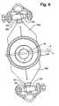
- Another structural feature found to be advantageousis the provision of a pair of one way clutches 151, 152 -- see FIG. 9 relative to the upper pivot shaft 122. These allow the pivot shafts to turn forward with brackets 120 and 121 but do not allow the shafts to follow the bracket backwards. This, in turn, causes the pivot shafts and associated bearings to maintain a constant forward index motion reducing cyclic motion wear problems which occur when bearings are simply oscillated.
Landscapes
- Engineering & Computer Science (AREA)
- Mechanical Engineering (AREA)
- Life Sciences & Earth Sciences (AREA)
- Forests & Forestry (AREA)
- Finish Polishing, Edge Sharpening, And Grinding By Specific Grinding Devices (AREA)
- Nonmetal Cutting Devices (AREA)
- Perforating, Stamping-Out Or Severing By Means Other Than Cutting (AREA)
- Replacement Of Web Rolls (AREA)
- Processing Of Stones Or Stones Resemblance Materials (AREA)
- Dovetailed Work, And Nailing Machines And Stapling Machines For Wood (AREA)
Description
- This invention relates to a method and apparatus fortransverse cutting and, more particularly, to a continuousmotion saw of the nature shown and described in co-owned PatentUS-RE. 30,598.
- A continuous motion saw is designed to cut a product inmotion. Illustrative products are "logs" of bathroom tissue andkitchen toweling. The invention, however, is not limited tosuch products but can be used to advantage on other multi-plyproducts, such as bolts of facial tissue, interfolded orotherwise.
- The illustrative products, for example, are produced athigh speed on machines termed "rewinders". These machines startwith a parent roll perhaps 3.05m (10 feet) long and 2.44m (8 feet) in diameter -- resulting from the output or a paper-making machine. Theparent roll is unwound to provide a web which is usuallytransversely perforated (in the U.S. on 11.4cm (4-1/2") centers forbathroom tissue and 27.9cm (11") centers for kitchen toweling and thenrewound into retail size rolls of 10.2cm-20.3cm (4"-8") in diameter.Conventional high speed automatic rewinders can produce upwardsof 30 logs per minute. These logs then are delivered to a logsaw where they are moved axially for severing into retail sizelengths -- again normally 11.4cm (4-1/2") for bathroom tissue and 27.9cm (11") forkitchen toweling. This results in the well-known "squares" oftissue and toweling.
- To have a saw capable of keeping up with high speedrewinders it is necessary to cut the log while it is in motion.To achieve a "square" cut on the moving log, the blade must havea cutting motion perpendicular to the log while also having amatched component of motion parallel of the log travel. Toproduce this combined motion, the orbit centerline of the bladeis "skewed" with respect to the log center line. This skewangle is increased for "long cut" lengths and is decreased for"short cut" lengths.
- Even though the saw head is mounted at this skewedangle, the blades must always remain perpendicular to the log toprovide a square cut. This required that the blades be mountedon an angled housing (equal and opposite to the skew cycle) anddriven by a 1:1 planetary motion to maintain their perpendicularrelation to the log as the main arm rotates.
- It was also necessary to maintain a razor-likesharpness on the cutting edge of the blades. To do this, the grinding system must be mounted on the angled housings andfollow the planetary motion. Because the grinders are mountedout on the blade's edge, each blade/grinder assembly isdifficult to balance, especially due to the changing position ofthe grinders as the blade diameter decreases. Since the systemwas generally out of balance, the planetary gear train had todeal with the constant imbalance torque and its cyclic nature,reversing once each revolution. The planetary motion also putthe grinder into completely reversing cyclic loading causingcomponent fatigue and grind quality problems as production speedrequirement increased.
- Problems were also associated with changing the skewangle to produce various product lengths. After changing theframework of the saw to a new skew angle, the blade mounting anddrive components had to be replaced. The angled block mountingthe blade had to be changed to return the blades back toperpendicular and the bevel gears inside it that were used todrive blades had to be changed to continue to match the angledhousing.
- These all combined to produce a complex cutterheadassembly that makes changing skew angles an involved andtime-consuming process. This system has also proven to becomplex causing high maintenance due to a complex blade driveand blade orienting planetary system. The design was also speedlimiting due to the planetary motion of the grinders causingcyclic loading and the requirement that the grinders follow thesame orbit radius of movement as the blades, causing them to have to withstand full centrifugal loading.
- The problem, therefore, was to produce this same typeof blade action but without the use of planetary motion. Forthis, the invention provides a motion that allows for locatingof the grinders at a lesser orbit radius than the blade centerand leaves them always toward the center of rotation, therebyeliminating the cyclic centrifugal forces. At the same time,the invention provides the ability to change the skew anglequickly, even automatically, with no change parts.
- The invention is defined in claim 1 below. In the specific embodimentof the invention illustrated, the blade, blade drive motor, and grinding stoneassemblies are mounted on the same mounting pivot bracket. Onebracket is mounted on each end of a rotating drive arm.Directly behind the arm is a control arm linkage connecting thetwo brackets from behind. The linkage, which has tie rodcharacteristics, is mounted off-center to the orbit headassembly center of rotation causing the blade and grinding stonemounting pivot brackets to oscillate back and forth as the armrotates. This action allows the blades to follow an eccentricpattern with respect to the axis of rotation to keep themperpendicular with the log or folded web. The entire orbit headassembly is mounted skewed with respect to the log or foldedweb. The amount of eccentricity is dependent on the skew angleof the orbit head assembly and the skew angle is dependent onthe linear speed of the log or folded web in order to achievethe desired square cut-off. The movable eccentric in thisinvention is also advantageous to bring the blades back to perpendicular as the skew angle changes correcting for changesof head skew. The amount of head skew is regulated through theuse of two skew adjustment linkages that the orbit head assemblyis mounted on. It could be done manually or automatically withsensors and drive motors which would allow changing the rate offeed of the log or folded web on the fly.
- In principle, the described continuous motion sawembodying the invention includes a frame providing a linear path or elongated webplies and conveyor means operatively associated with the framefor advancing the elongated web plies along the linear path.The frame also has a blade-equipped drive arm rotatably mountedthereon with means for rotating the drive arm about an axisskewed with respect to the linear path. A bracket is connectedadjacent an end of the drive arm for two degrees of pivotalmovement, the bracket or brackets also carrying the blade orblades. Means are provided on the bracket for rotating theblades. Thus, rotation of the blade arm orbits the blade orblades and the orbit resulting therefrom intersects the path.A control arm is rotatably mountedon the frame adjacent the blade arm for rotation about an axiseccentric to the blade arm axis. The control arm adjacent theend or ends thereof is connected to the bracket or bracketsagain for two degrees of pivotal freedom so that rotation ofboth of the arms orients the blade or blades perpendicular tothe linear path. This eliminates the planetary motion of theprior art and allows for the grinding stone assemblies if provided to remainclose to the center of rotation of the cutter head assembly -therebyreducing the centrifugal forces of the system and eliminating the cyclic nature of the force, thereby allowing for greater speeds.The new simplified construction which has the motor, blade and grindingassembly all attached to one pivot bracket and connected to a drive andcontrol arm offers a more user-friendly system with fewer parts, lower cost,less maintenance, greater speeds and more versatility.
- The drive arm, bracket means and control means referred to is claim 1 may make up agenerally planar four-bar linkage with said two degrees of pivotal freedombeing (a) generally parallel to the length of said drive arm and (b) generallyperpendicular to the linkage plane. Means may be interposed between saidcontrol means and frame means for adjusting the eccentricity of said control arm axis relative to said drive arm axis for cut length changes. A skew platemay be mounted on said frame means to define said skew axis, a drive shaftrotatably mounted in said skew plate and carrying said drive arm, saidadjusting means including bearing means for said control means, said bearingmeans being rotatably mounted on said skew plate for adjusting saideccentricity.
- Said bearing means may have an arcuate slot-equipped flange toprovide said eccentricity adjustment. Said bracket having the two degrees ofpivotal freedom may include means providing first a rotatability about anaxis generally parallel to the length of each arm and second rotatability aboutan axis perpendicular to the axis parallel to the length of each arm andgenerally perpendicular to said skewed axis, said rotatability-providing meansincluding clutch means to maintain a constant forward index motion.
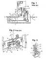
- FIG. 1 is a schematic side elevational view of acontinuous motion saw according to the prior art;
- FIG. 2 is a fragmentary perspective view of acontinuous motion saw according to the prior art;
- FIG. 3 is a schematic perspective view of a modelfeaturing the teachings of the instant invention;
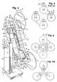
- FIG. 4 is an enlarged version of FIG. 3;
- FIG. 5 is a schematic view showing the orbiting of ablade according to the prior art continuous motion saw;
- FIG. 6 is a view similar to FIG. 5 but featuring theorbiting of the instant inventive saw;
- FIG. 6A is a view similar to FIG. 6 but of a modifiedembodiment of the invention;
- FIG. 7 is a top plan of a commercial embodiment of theinventive saw;
- FIG. 8 is a rear or upstream view of the saw as seenalong the sight line 8-8 of FIG. 7;
- FIG. 9 is a front or downstream view of the saw as seen along the sight line 9-9 of FIG. 7; and
- FIG. 10 is an end elevation of the saw as would be seenalong the line 10-10 of FIG. 9.
- Referring first to FIG. 1 the symbol F designatesgenerally the frame of the machine which can be seen in FIG. 2to include a pair of side frames.
- The frame F provides a path P which extends linearly,horizontally for the conveying of logs L and ultimately thesevered rolls R. The logs and thereafter the rolls are conveyedalong the path P by a suitable conveyor generally designated C.The symbol B designates generally the blade mechanism whichincludes two disc blades D -- see also FIG. 2. As can be seenfrom FIG. 2, there is provided a bracket for each blade as at Bwhich support the usual grinders G.
- The blades B and their associated structure are carriedby a skew plate SP which supports the skew arm A for rotationabout a skew axis S which is arranged at a minor acute angle to the path P (see the upper central portion of FIG. 2).
- The invention is first described in conjunction with amodel in FIG. 3. This permits the description of the basiccomponents free of many of the details present in the commercialmachine of FIGS. 7-10.
- In FIG. 3, the symbol F again designates generally aframe which provides a support for the skew plate now designated 11. As before, the
skew plate 11 carries theskew arm 12 whichin turn ultimately provides a support for orbiting, rotatingdisc blades -- here the blades are designated 13 versus D in theprior art showing. As can be appreciated from what has beensaid before, here the similarly ends between the invention andthe prior art. In particular, there is considerably moreinvolved in compensating for the skew angle between the axis Sof arm rotation and the path P. Instead of having theblades 13fixed at the compensating angle as were the disc blades D inFIGS. 1 and 2, the invention makes the compensation by employingan eccentric and pivotal connections providing two degrees ofpivotal freedom. For example, the prior art machine utilizedgears that were angled so as to maintain the disc blades Dalways perpendicular to the path P. This brought about theproblems previously discussed -- complexity of machinery andheavy cyclic "g" loads in particular. - In the invention as seen in the model showing of FIG.4, the eccentricity is provided by a
cylindrical bearing 14having an eccentric bore 15. Thebearing 14 is fixed in theskew plate 11. Extending through the off-center bore 15 is adrive shaft 16 which is fixedly coupled to theskew arm 12. Asindicated previously, theskew arm 12 does not itself carry thedisc blades 13 but does so through thedrive arm 17 which ispivotally connected as at 18, 19 to the ends of theskew arm 12. - Inasmuch as the
skew arm 12 is fixedly connected to thedrive shaft 16 and perpendicular thereto -- it rotates in aplane which is skewed relative to the path P, i.e.,perpendicular to the axis S. Theskew arm 12 is pivotallyconnected to thedrive arm 17 via longitudinally-extendingpivotposts lowerdisc blades 13. In turn, the clevis-like ends ofdrive arm 17are pivotally connected tobrackets pivot rods blades 13. - At their ends opposite the
blades 13, thebrackets pivot rods clevises - These clevises, in turn are pivotally connected vialongitudinally-extending
pivot posts control arm 30 -- also designated in FIG. 3. - The
control arm 30, in turn, is eccentrically mountedrelative to thedrive shaft 16 on bearing 14 -- see the centralleft portion of FIG. 4. - It is the combination of the
drive arm 17, thebrackets control arm 30 that compensates for the skewangle and positions theblades 13 perpendicular to the path Pso as to provide a "square" cut. But, unlike the prior art '889patent, this is not done by making a single compensation (viagears in the bracket B) but is done by using an eccentric plusconnections that provide at least two degrees of rotational orpivotal freedom. This can best be appreciated from adescription of what happens when the upper one of theblades 13travels in the direction of thearrow 31 from a 3 o'clock position -- as in the right hand portion in FIG. 6 -- to the 6o'clock position. - As a
blade 13 orbits from the 3 o'clock position towardcutting contact with a log, thedrive arm 17 pivots relative totheskew arm 12 -- this on the pivot posts 18, 19 as indicatedby thearrow 32. At the 3 o'clock position, the descending endof thecontrol arm 30 is in its furthest position from the skewaxis S, i.e., the axis of theshaft 16. This can be appreciatedfrom the location of the eccentric bore 15 -- see the left sideof FIG. 4. Then, as thecontrol arm 30 continues to rotate --by virtue of being coupled to theskew arm 12, throughbrackets arm 17 -- the descending end of thecontrol arm 30 comes closer and closer to the skew axis S, and is closest atthe 9 o'clock position. The other end of thecontrol arm 30follows the same pattern. - What this means is that the contribution of theeccentric mounting of the
control arm 30 toward compensating forskew varies, i.e., decreases in going from the 3 o'clockposition to the 9 o'clock position. This results in thecontrolarm 30 pulling thebracket 20 about thepivot post 28. Thispivot post is in theclevis 26 and thebracket 20 and themovement is designated by thearrow 33. - This necessarily occurs because the
control arm 30, theclevis connection 26, thebracket 20, the drive arm 17 (withskew arm 12),bracket 21 andclevis 27 form, in essence, agenerally planar four-bar linkage. This also includes thepivots shaft 16 is fixed to theskew arm 12 which in turn is fixed againstlongitudinal movement in thedrive arm 17. Thus, thepivots drive arm 17 and thepivots - However, at the same time, there is a rotation aboutthe longitudinally-extending
pivot posts skew arm 12 and also the counterpart longitudinally-extendingpivot posts control arm 30.This necessarily occurs because the eccentric mounting of thecontrol arm 30 on thebearing 14 produces a rectilinear movementof thecontrol arm 30, i.e., a movement that has both"horizontal" and "vertical" components. - This extra component results in a twisting of the drivearm 17 (permitted because of the pivotal connection with theskew arm 12) and which is reflected in changing the orientationof the
brackets blades 13. So theinventive arrangement compensates for the departure of theblades from "squareness" by virtue of being skewed by theeccentricity of thedrive shaft 16 and its coupling to afour-bar linkage. There are other ways of pivotally couplingthe various members of the four-bar linkage -- in particular,substituting at least a universal or spherical joint for thepivots - Reference now is made to FIGS. 5 and 6 which illustratea significant advantage of the invention. In FIG. 5 forexample, the grinders G -- see also FIG. 2 -- maintain the samerelationship to the frame throughout the orbit of the blades B,i.e., always being above the blades B. This results in aconstantly changing force on the grinders. For example, at aplanetary motion speed of 200 rpm the acceleration force Cgdue to centrifugal movement is 27.5 times "g". In contrast, inFIG. 6 while maintaining the same blade sweep radius and wherethe grinders do not follow a planetary movement but are alwaysoriented in the same distance from the axis of rotation of theblades, the force Cg is only 21.5 times "g" and this at higher250 rpm. This results from the grinders being mounted on the
brackets - It will be appreciated that the invention findsadvantageous application to saws with one or more blades. Theusual arrangement is with two blades as seen in FIG. 6.However, more blades can be used -- as, for example, the threeblade version of FIG. 6A. This is advantageous either with orwithout the four-bar linkage compensation for skew. The inboardplacement is helpful itself in reducing centrifugal forces andsubstantially eliminating cyclic loading.
- The invention has been described thus far in connectionwith a schematic model. Now the description is continued inconnection with an embodiment suitable for commercial usage -thisis connection with FIGS. 7-10.
- Here like numerals are employed as much as possible todesignate analogous elements -- but with the addition of 100 tothe previously employed numeral. Thus, looking at FIG. 7 in thelower left hand portion, it will be seen that the numeral 111designates the skew plate which is shown fragmentarily. Thishas rigidly fixed therein the bearing 114 (see the centralportion of FIG. 7) which rotatably carries the
drive shaft 116-- see the lower left hand portion of FIG. 7. Moving upwardlyat the left of FIG. 7, we see thedrive shaft 116. Affixed tothe right hand end ofdrive shaft 116, as at 116a, is theskewarm 112 -- seen in solid lines in the broken away portion of thedrive arm 117. - As before, there are pivot post connections between the
skew arm 112 and drivearm 117 as at 118 at the top and 119 atthe bottom. At its upper end, thedrive arm 117 is equippedwith a transversely extending pivot rod as at 122 and whichconnects thedrive arm 117 to theupper bracket 120. In similarfashion, thepivot rod 123 connects the lower end of thedrivearm 117 to thelower bracket 121. - Now considering the left hand end of the bracket 120(in the upper left hand portion of FIG. 7), the numeral 124designates a transversely extending pivot rod pivotally attached to bearing
housing 126 mounted on theupper end 130a of thecontrol arm generally-designated 130. Here, it will be notedthat thecontrol arm 130 is somewhat different from thestraightcontrol arm 30 of the model of FIGS. 3 and 4 in that it has twoparts, each associated with a different bracket as seen in FIG.7 -- 120 at theupper end lower end 130b.In between, the parts are connected by an enlargement toaccommodate the eccentric means as seen in FIG. 8. - The connection between the upper
control arm end 130aand the bearinghousing 126 can be best seen in the upperportion of FIG. 8 where thepivot rod 124 is also designated -asis the longitudinally extending pivot mounting 128. Anarrangement similar thereto is provided at thelower end 130b ofthecontrol arm 130 as seen in FIG. 8 where the cross pivot isdesignated 125, thelongitudinally extending pivot 129 and thebearinghousing 127. - Now returning to FIG. 7, it will be seen in the upperright hand corner that there is a mounting surface provided at134 and which carries the grinder associated with the
upper discblade 113. In similar fashion, asurface 135 is provided in thelower right hand portion of FIG. 7 for sharpening theotherblade 113. Because the constructions are the same for the upperand lower grinders and disc blades, only the one shown in theupper position in FIG. 7 will be described. Boltably secured tothesurface 134 is a bracket orarm member 136. This carries abearing 137 which in turn rotatably carries a shaft for thegrindingstone 138. Amotor 139 powers the grindingstone 138 to provide a beveled edge for theupper disc blade 113. - In the central left hand portion of FIG. 7, the numeral140 designates generally the assembly of elements which providethe adjustable eccentric. These include a
plate 141 which issecured to theskew plate 111 by the circular welds 142. - Positionably mounted on the
plate 141 is an eccentricbearing generally designated 143. Thebearing 143 is annularand has a flange portion as at 144 confronting theplate 141 anda cylindrical-like portion 145 which surround thebearing 114 inspaced relation thereto. - That the
bearing 143 is eccentric to thebearing 114can be appreciated from the fact that the upper portion as at145a (still referring to the central portion of FIG. 7) ismore distant from the bearing 114 than is thelower portion 145b. - Interposed between the
cylindrical portion 145 and thecontrol arms 130 is a ring bearing as at 146. Thus, when thecontrol arm 130 is moved by thebrackets arms brackets control arm 130 has its ends following an eccentric path basedupon the eccentricity of thebearing 14 relative to thedriveshaft 16, viz., the difference between axes E and S in FIGS. 4and 7. Thecontrol arm 30 is journalled on thebearing 14 forfree rotation thereon -- and this can be appreciated from the fact that thebearing 14 continues through thecontrol arm 30 ascan be appreciated from the portion of the bearing designated14a in FIG. 4 -- see the right central portion of FIG. 4. Addedto the commercial embodiment is the ability to adjust theeccentricity. - The adjustable feature for the eccentric 140 can bebest appreciated first from a consideration of FIG. 9. There,it is seen that the flange or
hub portion 144 is equipped withfourarcuate slots 147, each of which receives acap screw 148.The cap screws are further received within tapped openings intheplate 141 and when the cap screws are loosened, the hub orflange portion 144 of thebearing 143 can be "dialed" to thedesired position and thus change the eccentricity of thecontrolarm 130. It will be appreciated that the rotation of theeccentric could be achieved by pushbutton means using automaticclamp bolts at 148 and means for turning theflange 144. Thus,adjustment could be done while the saw is operating, usingfurther means for turning theskew plate 11 to the new skewangle. - The
curved slots 147 produce an 8:1 movement toreaction. Where lesser ratios are permissible, a rack andpinion system may be employed to obtain a 2:1 ratio. A plainlinear slide, using a track with jacking screws and clamps, canprovide a 1:1 ratio. - Although the invention has been described inconjunction with the usual two bladed continuous motion saw, it will be appreciated that the advantages of the invention may beapplied to saws with one, three or four blades inasmuch as theinvention permits a balancing of forces through the geometry ofthe controlling linkage. With a single blade, for example, asuitable counterweight is provided on the arm end lacking theblade.
- The blade structure can be readily appreciated from aconsideration of both the upper portion of FIG. 7 and FIG. 10.In FIG. 7, the
disc blade 113 is carried on a spindle orshaft 149 and is suitably rotated by means of amotor 150. - Another structural feature found to be advantageous isthe provision of a pair of one
way clutches upper pivot shaft 122. These allow the pivotshafts to turn forward withbrackets
Claims (6)
- An orbital log or bolt saw for cutting logs of bathroom tissue andkitchen toweling or multi-ply bolts of facial tissue or interfolded intoretail size lengths comprising:characterized in thatframe means (F) providing a linear path (P) for elongated web plies(L), the frame means including a skew plate (11,111) mounted at an adjustable angle,conveyor means (C) operatively associated with said frame meansfor advancing said elongated web plies along said linear path,a blade-equipped relatively elongated drive arm (17, 117) rotatablymounted on said skew plate, means (16, 116) on said frame means for rotatingsaid drive arm about an axis (S) skewed with respect to said linear path to orbit theblades, the blade orbit intersecting said linear path, said skewed axis beingadjustable by varying the angle of the skew plate,bracket means (20, 21, 120, 121) mounted adjacent an end of saiddrive arm and having thereon means (150) for rotating said blade,
the bracket means is mounted such as to provide two degrees ofpivotal freedom and carries said blade (13,113),
a control arm (30, 130) is provided parallel to said drive arm which isrotatably mounted on said skew plate for rotation about an axis (E) eccentric tosaid drive arm axis (S) in a plane between the skew plate and the drive arm andcoupled to the drive arm so as to rotate therewith thereby producing anoscillating motion in said control arm relative to said drive arm, said control armbeing connected to said bracket means to transmit the oscillating motion theretoto compensate for the skew of said drive arm by pivoting the bracket means inthe two degrees of freedom to orient said blade perpendicular to said web pliesin the linear path when engaging the same. - The saw of claim 1 in which said bracket means is equipped with agrinding stone (G, 138) for said blade, said grinding stone being positioned radially inwardly of said blade whereby centrifugal forces are reduced and cyclicloading is substantially eliminated.
- The saw of claim 1 or 2 in which said drive arm, bracket means andcontrol means make up a generally planar four-bar linkage with said twodegrees of pivotal freedom being (a) generally parallel to the length of said drivearm and (b) generally perpendicular to the linkage plane.
- The saw of claim 1, 2 or 3 in which means (140) are interposed betweensaid control means (30, 130) and frame means (F) for adjusting the eccentricity ofsaid control arm axis (E) relative to said drive arm axis (S) for cut length changes.
- The saw of claim 4 in whicha drive shaft (16, 116) is rotatably mountedin said skew plate and carrying said drive arm (17, 117), said adjusting meansincluding bearing means (143) for said control means, said bearing means beingrotatably mounted on said skew plate for adjusting said eccentricity, andpreferably comprising an arcuate slot-equipped flange (144) to provide saideccentricity adjustment.
- The saw of any preceding claim, in which the degrees of pivotal freedomare provided by means providing first a rotatability about an axis generallyparallel to the length of each arm and second rotatability about an axisperpendicular to the axis parallel to the length of each arm and generallyperpendicular to said skewed axis, said rotatability-providing means includingclutch means (151, 152) to maintain a constant forward index motion.
Priority Applications (1)
| Application Number | Priority Date | Filing Date | Title |
|---|---|---|---|
| EP05013731AEP1584428A1 (en) | 1994-04-06 | 1995-01-12 | Method and apparatus for transverse cutting |
Applications Claiming Priority (3)
| Application Number | Priority Date | Filing Date | Title |
|---|---|---|---|
| US223543 | 1994-04-06 | ||
| US08/223,543US5557997A (en) | 1994-04-06 | 1994-04-06 | Apparatus for transverse cutting |
| EP95100386AEP0677360B1 (en) | 1994-04-06 | 1995-01-12 | Method and apparatus for transverse cutting |
Related Parent Applications (2)
| Application Number | Title | Priority Date | Filing Date |
|---|---|---|---|
| EP95100386ADivisionEP0677360B1 (en) | 1994-04-06 | 1995-01-12 | Method and apparatus for transverse cutting |
| EP95100386.2Division | 1995-01-12 |
Related Child Applications (1)
| Application Number | Title | Priority Date | Filing Date |
|---|---|---|---|
| EP05013731ADivisionEP1584428A1 (en) | 1994-04-06 | 1995-01-12 | Method and apparatus for transverse cutting |
Publications (3)
| Publication Number | Publication Date |
|---|---|
| EP1120208A2 EP1120208A2 (en) | 2001-08-01 |
| EP1120208A3 EP1120208A3 (en) | 2001-09-26 |
| EP1120208B1true EP1120208B1 (en) | 2005-10-26 |
Family
ID=22836959
Family Applications (3)
| Application Number | Title | Priority Date | Filing Date |
|---|---|---|---|
| EP05013731AWithdrawnEP1584428A1 (en) | 1994-04-06 | 1995-01-12 | Method and apparatus for transverse cutting |
| EP95100386AExpired - LifetimeEP0677360B1 (en) | 1994-04-06 | 1995-01-12 | Method and apparatus for transverse cutting |
| EP01110427AExpired - LifetimeEP1120208B1 (en) | 1994-04-06 | 1995-01-12 | Apparatus for transverse cutting |
Family Applications Before (2)
| Application Number | Title | Priority Date | Filing Date |
|---|---|---|---|
| EP05013731AWithdrawnEP1584428A1 (en) | 1994-04-06 | 1995-01-12 | Method and apparatus for transverse cutting |
| EP95100386AExpired - LifetimeEP0677360B1 (en) | 1994-04-06 | 1995-01-12 | Method and apparatus for transverse cutting |
Country Status (6)
| Country | Link |
|---|---|
| US (3) | US5557997A (en) |
| EP (3) | EP1584428A1 (en) |
| JP (1) | JP3497275B2 (en) |
| CA (1) | CA2138005C (en) |
| DE (3) | DE69534552D1 (en) |
| ES (1) | ES2169090T3 (en) |
Cited By (1)
| Publication number | Priority date | Publication date | Assignee | Title |
|---|---|---|---|---|
| CN111055319A (en)* | 2019-12-13 | 2020-04-24 | 湖州荣立包装材料有限公司 | Packaging paper cutting device for packaging mechanical equipment |
Families Citing this family (58)
| Publication number | Priority date | Publication date | Assignee | Title |
|---|---|---|---|---|
| US5557997A (en)* | 1994-04-06 | 1996-09-24 | Paper Converting Machine Company | Apparatus for transverse cutting |
| DE19504162C2 (en)* | 1995-02-08 | 1997-02-20 | Windmoeller & Hoelscher | Knife roller changeable in diameter |
| GB2307432B (en)* | 1995-11-21 | 1999-05-26 | Rolls Royce & Ass | A sample removing tool |
| ES2188934T3 (en)* | 1996-09-23 | 2003-07-01 | Ahti Niemela | MECHANICAL SAW. |
| US6272960B1 (en)* | 1998-06-03 | 2001-08-14 | Black & Decker Inc. | Chop saw |
| US6010090A (en)* | 1998-12-11 | 2000-01-04 | Paper Converting Machine Co. | Method of perforating a web |
| US20010047708A1 (en) | 1999-04-01 | 2001-12-06 | Andre A. Lavallee | Paper removal device |
| US6224468B1 (en) | 1999-07-15 | 2001-05-01 | Paper Converting Machine Company | Apparatus and method for sharpening a disc blade |
| US6615699B2 (en)* | 1999-09-17 | 2003-09-09 | Ferag Ag | Method and device for cutting continuously conveyed, flat objects |
| IT1308313B1 (en)* | 1999-11-17 | 2001-12-10 | Perini Fabio Spa | SHARPENING DEVICE FOR ROTARY CUTTING TOOLS AND MACHINE USING THE DEVICE. |
| IT1314595B1 (en)* | 2000-03-28 | 2002-12-20 | Perini Fabio Spa | MULTIPLE CUTTING-OFF MACHINE FOR PRODUCTS IN TAPE MATERIAL WITH A BLADE SHARPENING AREA SEPARATED FROM THE CUTTING AREA |
| IT1317794B1 (en)* | 2000-06-01 | 2003-07-15 | Giovanni Gambini | CUTTING HEAD OF MULTIPLE ROLLS OF DRY AND / OR HYGIENIC PAPER |
| IT1318260B1 (en)* | 2000-07-27 | 2003-07-28 | Giovanni Gambini | SHARPENING GROUP WITH DISK WEAR RECOVERY FOR CUTTING MACHINE OF STICKS OR LOG |
| DE10060552A1 (en)* | 2000-12-06 | 2002-06-13 | Hauni Maschinenbau Ag | Cutting device and method for changing cutting means |
| US6532851B2 (en) | 2000-12-21 | 2003-03-18 | Paper Converting Machine Company | Apparatus for supporting product during cutting |
| US20020117030A1 (en)* | 2000-12-22 | 2002-08-29 | Gambaro Anthony M. | Multi-blade log saw |
| US6644154B2 (en) | 2001-04-27 | 2003-11-11 | Paper Converting Machine Co. | Apparatus for transverse cutting |
| US20030199945A1 (en)* | 2002-02-11 | 2003-10-23 | James Ciulla | Device and method for treating disordered breathing |
| US7810419B2 (en) | 2003-02-05 | 2010-10-12 | C.G. Bretting Manufacturing Co., Inc. | Rotating log clamp |
| EP1639232A2 (en)* | 2003-06-17 | 2006-03-29 | Mehmet Salih Atak | A device having multiple driving arms rotated circularly without axial rotation and the method of the same |
| WO2005009696A1 (en)* | 2003-07-23 | 2005-02-03 | Cfs Kempten Gmbh | Axially-displaceable cutter and cutting gap adjustment |
| US6994206B2 (en)* | 2004-02-05 | 2006-02-07 | Paper Converting Machine Company | Apparatus for feeding rolls of cut products to a wrapper |
| DE602004015065D1 (en)* | 2004-03-31 | 2008-08-28 | Mtc Macchine Trasformazione | Clamping device for a machine for the transverse cutting of rod-shaped paper goods |
| ITFI20040079A1 (en)* | 2004-04-01 | 2004-07-01 | Perini Fabio Spa | CUTTING MACHINE WITH CENTRAL SHARPENING SYSTEM |
| US7634958B2 (en)* | 2005-04-05 | 2009-12-22 | Baugher Robert C | Rotary cutter |
| ITFI20050113A1 (en)* | 2005-05-27 | 2006-11-28 | Perini Fabio Spa | CUTTING MACHINE FOR CUTTING ROLLS OR LOGS OF TWO-TONE MATERIALS AND RELATED METHOD |
| US8219173B2 (en) | 2008-09-30 | 2012-07-10 | Abbott Diabetes Care Inc. | Optimizing analyte sensor calibration |
| US20080028902A1 (en)* | 2006-08-03 | 2008-02-07 | Kimberly-Clark Worldwide, Inc. | Dual roll, variable sheet-length, perforation system |
| US20080216975A1 (en)* | 2007-03-05 | 2008-09-11 | James Paul Farwig | Deeply embossed roll paper products having reduced gapping on the machine direction edges |
| DE102009041776A1 (en)* | 2009-09-15 | 2011-03-24 | Hauni Maschinenbau Ag | Knife carrier for a cutting device in extrusion machines of the tobacco processing industry |
| US20110126679A1 (en)* | 2009-12-02 | 2011-06-02 | Weber Maschinenbau Gmbh Breidenbach | Apparatus for slicing food products |
| EP2357064B1 (en)* | 2009-12-21 | 2015-09-23 | Weber Maschinenbau GmbH Breidenbach | Device for cutting a food product |
| ITLU20110017A1 (en)* | 2011-11-23 | 2013-05-24 | Licari Marina | SEQUENTIAL CUTTING-OFF MACHINE |
| US20130139664A1 (en) | 2011-12-06 | 2013-06-06 | Paper Converting Machine Company | Method and apparatus for supporting product during cutting |
| ITMI20130178A1 (en)* | 2013-02-08 | 2014-08-09 | Gambini Int Sa | GROUP FOR THE DISTRIBUTION OF A CONTINUOUS TUBULAR IN ADVANCE IN A PLURALITY OF TUBULAR ELEMENTS |
| US9227288B2 (en) | 2013-03-15 | 2016-01-05 | Sca Hygiene Products Ab | Blade honing apparatus and cutting apparatus incorporating same |
| CN103640045B (en) | 2013-09-09 | 2016-08-10 | 宇宙纸巾技术有限公司 | Knife sharpening device and cutting machine |
| CN103640041B (en)* | 2013-09-09 | 2016-02-10 | 宇宙纸巾技术有限公司 | Round knife cutting device |
| US9227298B2 (en) | 2014-01-31 | 2016-01-05 | Kimberly-Clark Worldwide, Inc. | Saw blade sharpening apparatus |
| EP2921268B1 (en)* | 2014-03-19 | 2016-12-14 | Universal Tissue Technology S.R.L. | Log saw machine |
| BR112017003665B1 (en)* | 2014-08-29 | 2021-05-18 | Fabio Perini S.P.A. | cutting machine, method for adjusting the reciprocal position between disc-shaped cutting blade and disc-shaped cutting blade grinding method |
| US10806635B2 (en) | 2016-03-15 | 2020-10-20 | The Procter & Gamble Company | Methods and apparatuses for separating and positioning discrete articles |
| CN108858836A (en)* | 2017-05-10 | 2018-11-23 | 深圳市沃福泰克科技有限公司 | Diamond band-saw cutting machine control system and method |
| US10946546B2 (en)* | 2017-09-01 | 2021-03-16 | Paper Converting Machine Company | Apparatus and method for automated blade change for tissue saw |
| CN107553257A (en)* | 2017-10-25 | 2018-01-09 | 德清凯晶光电科技有限公司 | Cylindrical mirror blank polisher |
| US11571758B2 (en) | 2018-11-30 | 2023-02-07 | Paper Converting Machine Company | Method of cleaning blade of log saw |
| IT201900008493A1 (en)* | 2019-06-10 | 2020-12-10 | Futura Spa | Cutting-off machine for logs of paper material. |
| IT201900008490A1 (en)* | 2019-06-10 | 2020-12-10 | Futura Spa | Miter saw machine. |
| CN111113521B (en)* | 2020-02-27 | 2021-03-09 | 广州基俊机械科技有限公司 | Workpiece cutting device with multi-angle tangent plane |
| CN111515831B (en)* | 2020-04-13 | 2021-07-20 | 广东长盈精密技术有限公司 | A multi-angle automatic polishing device |
| CN111975576B (en)* | 2020-07-06 | 2022-01-25 | 东莞华骏电梯有限公司 | Pin rod processing device for processing elevator safety pin |
| CN112677200B (en)* | 2020-12-02 | 2022-12-02 | 中烟机械技术中心有限责任公司 | Filter tip cutting device |
| CN113199530A (en)* | 2021-05-26 | 2021-08-03 | 郑州智联机械设备有限公司 | Disc rotary-cut formula cutting device |
| CN114799904B (en)* | 2022-04-13 | 2022-10-04 | 徐州腾鸿建设工程有限公司 | End processing device and method for steel structure for building |
| CN115383829B (en)* | 2022-09-14 | 2024-05-14 | 抚州市天和硅业有限责任公司 | Small-size blocking assistor is used in organosilicon production |
| CN116038015B (en)* | 2023-02-01 | 2023-08-08 | 三铃金属制品(东莞)有限公司 | High-temperature cutting device and method for copper material |
| TWI890296B (en)* | 2023-11-06 | 2025-07-11 | 日商日本製鐵股份有限公司 | Cutting device, cutting method and multi-layer material |
| WO2025165528A1 (en) | 2024-02-02 | 2025-08-07 | Bw Converting, Inc. | Conveyor system for moving folded, stacked webs of material |
Family Cites Families (41)
| Publication number | Priority date | Publication date | Assignee | Title |
|---|---|---|---|---|
| US30598A (en)* | 1860-11-06 | Apparatus fob tanning | ||
| US1630132A (en)* | 1924-10-01 | 1927-05-24 | Molins Walter Everett | Cigarette-making machine |
| GB248415A (en)* | 1924-10-01 | 1926-03-01 | Walter Everett Molins | Improvements in and relating to cigarette making machines |
| US1746594A (en)* | 1926-01-18 | 1930-02-11 | Axcel C Jacobson | Sawing machine |
| US1784443A (en)* | 1927-11-21 | 1930-12-09 | Firm Universelle Cigarettenmas | Cigarette-making machine |
| GB307153A (en)* | 1928-01-10 | 1929-03-07 | Walter Everett Molins | Improvements in or relating to cigarette making machines |
| US1846942A (en)* | 1929-09-18 | 1932-02-23 | American Mach & Foundry | Cut-off for high-speed cigarette machines |
| GB337225A (en)* | 1929-11-15 | 1930-10-30 | American Mach & Foundry | Improvements in cutoff for high speed cigarette making machine |
| GB452180A (en)* | 1934-09-10 | 1936-08-18 | Clara Quester | Improvements in or relating to cutting devices for continuous rod cigarette and like machines |
| US2093323A (en)* | 1935-08-24 | 1937-09-14 | Acme Detroit Saw Corp | Slicing machine |
| US2140720A (en)* | 1935-12-17 | 1938-12-20 | Molins Machine Co Ltd | Apparatus for severing an axially moving rod into lengths |
| DE930737C (en)* | 1949-02-16 | 1955-07-21 | Austria Tabakwerke Ag | Cutting device for straight cigarette machines |
| US2769600A (en)* | 1952-07-16 | 1956-11-06 | Paper Converting Machine Co | Web winding machine |
| US2752999A (en)* | 1953-01-19 | 1956-07-03 | Gilbertville Woven Label Corp | Automatic cutting machine |
| US2704560A (en)* | 1953-02-12 | 1955-03-22 | Gibraltar Mfg Co Inc | Tilt arbor bench saw |
| US2779413A (en)* | 1954-06-23 | 1957-01-29 | Gilbertville Woven Label Corp | Automatic loader |
| US2776566A (en)* | 1954-06-24 | 1957-01-08 | Exxon Research Engineering Co | Apparatus for measuring the flow rates of particulate solids |
| US2833024A (en)* | 1955-03-31 | 1958-05-06 | Mannesmann Meer Ag | Rotary saw |
| US2879633A (en)* | 1956-12-04 | 1959-03-31 | Gilbertville Woven Label Corp | Sharpening device for cutting wheel |
| US3049954A (en)* | 1957-06-03 | 1962-08-21 | Fmc Corp | Apparatus for cutting articles |
| NL288128A (en)* | 1962-01-31 | 1900-01-01 | ||
| US3213734A (en)* | 1964-07-24 | 1965-10-26 | Paper Converting Machine Co | Orbital saw having varying orbit speed within each orbit |
| US3213731A (en)* | 1964-08-04 | 1965-10-26 | John J Renard | Paper log cutting apparatus |
| US3292470A (en)* | 1965-10-18 | 1966-12-20 | Paper Converting Machine Co | Orbital saw |
| US3380331A (en)* | 1966-04-06 | 1968-04-30 | Philip Morris Inc | Apparatus for sectioning moving articles |
| US3905260A (en)* | 1974-09-06 | 1975-09-16 | Paper Converting Machine Co | Log sawing system |
| GB1503209A (en)* | 1975-06-14 | 1978-03-08 | Molins Ltd | Sharpener for cut-off having a helical knife |
| US4041813A (en)* | 1976-02-17 | 1977-08-16 | Paper Converting Machine Company | Method and apparatus for transverse cutting |
| US4052048A (en)* | 1976-03-11 | 1977-10-04 | Paper Converting Machine Company | Longitudinally interfolding device and method |
| US4173846A (en)* | 1978-01-23 | 1979-11-13 | Paper Converting Machine Company | Orbital saw sharpening device |
| USRE30598E (en)* | 1979-02-14 | 1981-05-05 | Paper Converting Machine Company | Method for transverse cutting |
| US4347771A (en)* | 1980-11-10 | 1982-09-07 | Paper Converting Machine Company | Apparatus for sharpening a disc |
| US4584917A (en)* | 1984-12-06 | 1986-04-29 | Paper Converting Machine Company | Automatic blade diameter compensation for log saws |
| US4821613A (en)* | 1987-06-19 | 1989-04-18 | Paper Converting Machine Company | Method and apparatus for log saw blade sharpening |
| IT1213652B (en)* | 1987-07-22 | 1989-12-29 | Gd Spa | DEVICE FOR THE CROSS-CUTTING OF A MOBILE BELT OF CONTINUOUS MOTORCYCLE ALONG A DETERMINED PATH |
| IT1233279B (en)* | 1989-04-05 | 1992-03-26 | Perini Finanziaria Spa | CUTTING MACHINE FOR CUTTING STICKS OF PAPER AND SIMILAR MATERIAL |
| IT1247330B (en)* | 1991-04-03 | 1994-12-12 | Perini Fabio Spa | CUTTING MACHINE FOR CUTTING ROLLS OF TAPE MATERIAL. |
| US5152203A (en)* | 1991-08-19 | 1992-10-06 | Paper Converting Machine Company | Apparatus and method for sharpening saw blades having planetary motion in transverse cutting |
| IT1258171B (en)* | 1992-02-07 | 1996-02-20 | Perini Fabio Spa | CUTTING METHOD AND CUTTING MACHINE FOR PAPER ROLLS AND SIMILAR |
| US5289747A (en)* | 1993-02-04 | 1994-03-01 | Paper Converting Machine Company | Variable velocity conveying method and apparatus for continuous motion saws |
| US5557997A (en)* | 1994-04-06 | 1996-09-24 | Paper Converting Machine Company | Apparatus for transverse cutting |
- 1994
- 1994-04-06USUS08/223,543patent/US5557997A/ennot_activeExpired - Lifetime
- 1994-12-13CACA002138005Apatent/CA2138005C/ennot_activeExpired - Fee Related
- 1995
- 1995-01-12DEDE69534552Tpatent/DE69534552D1/ennot_activeExpired - Lifetime
- 1995-01-12EPEP05013731Apatent/EP1584428A1/ennot_activeWithdrawn
- 1995-01-12DEDE69524278Tpatent/DE69524278T2/ennot_activeExpired - Fee Related
- 1995-01-12DEDE1120208Tpatent/DE1120208T1/enactivePending
- 1995-01-12EPEP95100386Apatent/EP0677360B1/ennot_activeExpired - Lifetime
- 1995-01-12EPEP01110427Apatent/EP1120208B1/ennot_activeExpired - Lifetime
- 1995-01-12ESES95100386Tpatent/ES2169090T3/ennot_activeExpired - Lifetime
- 1995-04-06JPJP10802395Apatent/JP3497275B2/ennot_activeExpired - Fee Related
- 1996
- 1996-09-17USUS08/718,089patent/US5924346A/ennot_activeExpired - Lifetime
- 1996-09-17USUS08/724,049patent/US6123002A/ennot_activeExpired - Lifetime
Cited By (2)
| Publication number | Priority date | Publication date | Assignee | Title |
|---|---|---|---|---|
| CN111055319A (en)* | 2019-12-13 | 2020-04-24 | 湖州荣立包装材料有限公司 | Packaging paper cutting device for packaging mechanical equipment |
| CN111055319B (en)* | 2019-12-13 | 2022-05-10 | 浙江科仓智能科技有限公司 | Packaging paper cutting device for packaging mechanical equipment |
Also Published As
| Publication number | Publication date |
|---|---|
| DE69534552D1 (en) | 2005-12-01 |
| EP0677360A1 (en) | 1995-10-18 |
| DE69524278T2 (en) | 2002-06-13 |
| CA2138005A1 (en) | 1995-10-07 |
| CA2138005C (en) | 2005-02-08 |
| EP1120208A3 (en) | 2001-09-26 |
| US5557997A (en) | 1996-09-24 |
| EP1120208A2 (en) | 2001-08-01 |
| JP3497275B2 (en) | 2004-02-16 |
| US6123002A (en) | 2000-09-26 |
| EP0677360B1 (en) | 2001-12-05 |
| EP1584428A1 (en) | 2005-10-12 |
| DE69524278D1 (en) | 2002-01-17 |
| JPH0839480A (en) | 1996-02-13 |
| US5924346A (en) | 1999-07-20 |
| DE1120208T1 (en) | 2003-03-06 |
| ES2169090T3 (en) | 2002-07-01 |
Similar Documents
| Publication | Publication Date | Title |
|---|---|---|
| EP1120208B1 (en) | Apparatus for transverse cutting | |
| CA1064705B (en) | Method and apparatus for transverse cutting | |
| US4584917A (en) | Automatic blade diameter compensation for log saws | |
| USRE30598E (en) | Method for transverse cutting | |
| JP2588463B2 (en) | Method and apparatus for grinding a planetary saw blade in transverse cutting | |
| US4063493A (en) | Rotary die cutting machine | |
| CA2582489A1 (en) | Improved edge trimming and board ripping apparatus and method | |
| US20230128556A1 (en) | Blade assembly and retraction mechanism for a high-speed food slicing apparatus | |
| EP0982104B1 (en) | Method and apparatus for moving the circular cutter of a machine for cutting logs of paper and the like | |
| US6644154B2 (en) | Apparatus for transverse cutting | |
| EP1078720B1 (en) | Method and apparatus for sharpening a disc blade | |
| FI88126C (en) | Bed sledge for a veneer turn to cut veneer from a log | |
| JPH037568A (en) | Method of regulating and controlling equipment for cutting strip material | |
| EP1175974B1 (en) | Sharpening unit with disc wear recovery for stick or log cutting machine | |
| CN214025908U (en) | A shearing machine with strong versatility | |
| CN216609167U (en) | Circular disc rotary cutting device | |
| CN214419723U (en) | Novel paperboard line cutting machine | |
| CN213946585U (en) | Slitting machine | |
| JPS5834710A (en) | Link type running shearing machine | |
| EP0970784B1 (en) | Cutting device for rolls of web material | |
| WO2000061325A1 (en) | Overspeed helical rotary knife | |
| US20050166746A1 (en) | Rotary tab cutter | |
| JPS6411437B2 (en) | ||
| WO1999036218A1 (en) | Flying drum shear |
Legal Events
| Date | Code | Title | Description |
|---|---|---|---|
| PUAI | Public reference made under article 153(3) epc to a published international application that has entered the european phase | Free format text:ORIGINAL CODE: 0009012 | |
| AC | Divisional application: reference to earlier application | Ref document number:677360 Country of ref document:EP | |
| AK | Designated contracting states | Kind code of ref document:A2 Designated state(s):DE ES FR GB IT SE | |
| PUAL | Search report despatched | Free format text:ORIGINAL CODE: 0009013 | |
| AK | Designated contracting states | Kind code of ref document:A3 Designated state(s):DE ES FR GB IT SE | |
| RIN1 | Information on inventor provided before grant (corrected) | Inventor name:WUNDERLICH, GARY R. Inventor name:WIERSCHKE, LARRY D. | |
| 17P | Request for examination filed | Effective date:20011112 | |
| AKX | Designation fees paid | Free format text:DE ES FR GB IT SE | |
| DET | De: translation of patent claims | ||
| 17Q | First examination report despatched | Effective date:20040723 | |
| GRAP | Despatch of communication of intention to grant a patent | Free format text:ORIGINAL CODE: EPIDOSNIGR1 | |
| RTI1 | Title (correction) | Free format text:APPARATUS FOR TRANSVERSE CUTTING | |
| GRAS | Grant fee paid | Free format text:ORIGINAL CODE: EPIDOSNIGR3 | |
| GRAA | (expected) grant | Free format text:ORIGINAL CODE: 0009210 | |
| AC | Divisional application: reference to earlier application | Ref document number:0677360 Country of ref document:EP Kind code of ref document:P | |
| AK | Designated contracting states | Kind code of ref document:B1 Designated state(s):DE ES FR GB IT SE | |
| PG25 | Lapsed in a contracting state [announced via postgrant information from national office to epo] | Ref country code:IT Free format text:LAPSE BECAUSE OF FAILURE TO SUBMIT A TRANSLATION OF THE DESCRIPTION OR TO PAY THE FEE WITHIN THE PRE;WARNING: LAPSES OF ITALIAN PATENTS WITH EFFECTIVE DATE BEFORE 2007 MAY HAVE OCCURRED AT ANY TIME BEFORE 2007. THE CORRECT EFFECTIVE DATE MAY BE DIFFERENT FROM THE ONE RECORDED.SCRIBED TIME-LIMIT Effective date:20051026 | |
| REG | Reference to a national code | Ref country code:GB Ref legal event code:FG4D | |
| REF | Corresponds to: | Ref document number:69534552 Country of ref document:DE Date of ref document:20051201 Kind code of ref document:P | |
| PG25 | Lapsed in a contracting state [announced via postgrant information from national office to epo] | Ref country code:GB Free format text:LAPSE BECAUSE OF NON-PAYMENT OF DUE FEES Effective date:20060126 Ref country code:SE Free format text:LAPSE BECAUSE OF FAILURE TO SUBMIT A TRANSLATION OF THE DESCRIPTION OR TO PAY THE FEE WITHIN THE PRESCRIBED TIME-LIMIT Effective date:20060126 | |
| PG25 | Lapsed in a contracting state [announced via postgrant information from national office to epo] | Ref country code:DE Free format text:LAPSE BECAUSE OF FAILURE TO SUBMIT A TRANSLATION OF THE DESCRIPTION OR TO PAY THE FEE WITHIN THE PRESCRIBED TIME-LIMIT Effective date:20060127 | |
| PG25 | Lapsed in a contracting state [announced via postgrant information from national office to epo] | Ref country code:ES Free format text:LAPSE BECAUSE OF FAILURE TO SUBMIT A TRANSLATION OF THE DESCRIPTION OR TO PAY THE FEE WITHIN THE PRESCRIBED TIME-LIMIT Effective date:20060206 | |
| PLBE | No opposition filed within time limit | Free format text:ORIGINAL CODE: 0009261 | |
| STAA | Information on the status of an ep patent application or granted ep patent | Free format text:STATUS: NO OPPOSITION FILED WITHIN TIME LIMIT | |
| GBPC | Gb: european patent ceased through non-payment of renewal fee | Effective date:20060126 | |
| 26N | No opposition filed | Effective date:20060727 | |
| EN | Fr: translation not filed | ||
| PG25 | Lapsed in a contracting state [announced via postgrant information from national office to epo] | Ref country code:FR Free format text:LAPSE BECAUSE OF FAILURE TO SUBMIT A TRANSLATION OF THE DESCRIPTION OR TO PAY THE FEE WITHIN THE PRESCRIBED TIME-LIMIT Effective date:20061215 | |
| PG25 | Lapsed in a contracting state [announced via postgrant information from national office to epo] | Ref country code:FR Free format text:LAPSE BECAUSE OF FAILURE TO SUBMIT A TRANSLATION OF THE DESCRIPTION OR TO PAY THE FEE WITHIN THE PRESCRIBED TIME-LIMIT Effective date:20060131 | |
| PG25 | Lapsed in a contracting state [announced via postgrant information from national office to epo] | Ref country code:FR Free format text:LAPSE BECAUSE OF FAILURE TO SUBMIT A TRANSLATION OF THE DESCRIPTION OR TO PAY THE FEE WITHIN THE PRESCRIBED TIME-LIMIT Effective date:20051026 |