EP1110599B1 - Dynamic mixer for dental impression pastes - Google Patents
Dynamic mixer for dental impression pastesDownload PDFInfo
- Publication number
- EP1110599B1 EP1110599B1EP99125804AEP99125804AEP1110599B1EP 1110599 B1EP1110599 B1EP 1110599B1EP 99125804 AEP99125804 AEP 99125804AEP 99125804 AEP99125804 AEP 99125804AEP 1110599 B1EP1110599 B1EP 1110599B1
- Authority
- EP
- European Patent Office
- Prior art keywords
- dynamic mixer
- mixing
- mixer according
- rotor
- chambers
- Prior art date
- Legal status (The legal status is an assumption and is not a legal conclusion. Google has not performed a legal analysis and makes no representation as to the accuracy of the status listed.)
- Expired - Lifetime
Links
- 239000000203mixtureSubstances0.000claimsdescription11
- 239000005548dental materialSubstances0.000claims1
- 239000000463materialSubstances0.000claims1
- 238000000465mouldingMethods0.000claims1
- 230000000694effectsEffects0.000description4
- 238000002347injectionMethods0.000description2
- 239000007924injectionSubstances0.000description2
- 230000003993interactionEffects0.000description2
- 238000000034methodMethods0.000description2
- 230000008878couplingEffects0.000description1
- 238000010168coupling processMethods0.000description1
- 238000005859coupling reactionMethods0.000description1
- 239000002978dental impression materialSubstances0.000description1
- 238000005516engineering processMethods0.000description1
- 238000003825pressingMethods0.000description1
- 238000003756stirringMethods0.000description1
Images
Classifications
- A—HUMAN NECESSITIES
- A61—MEDICAL OR VETERINARY SCIENCE; HYGIENE
- A61C—DENTISTRY; APPARATUS OR METHODS FOR ORAL OR DENTAL HYGIENE
- A61C9/00—Impression cups, i.e. impression trays; Impression methods
- A61C9/0026—Syringes or guns for injecting impression material; Mixing impression material for immediate use
- A—HUMAN NECESSITIES
- A61—MEDICAL OR VETERINARY SCIENCE; HYGIENE
- A61C—DENTISTRY; APPARATUS OR METHODS FOR ORAL OR DENTAL HYGIENE
- A61C5/00—Filling or capping teeth
- A61C5/60—Devices specially adapted for pressing or mixing capping or filling materials, e.g. amalgam presses
- A61C5/62—Applicators, e.g. syringes or guns
- A61C5/64—Applicators, e.g. syringes or guns for multi-component compositions
- B—PERFORMING OPERATIONS; TRANSPORTING
- B01—PHYSICAL OR CHEMICAL PROCESSES OR APPARATUS IN GENERAL
- B01F—MIXING, e.g. DISSOLVING, EMULSIFYING OR DISPERSING
- B01F33/00—Other mixers; Mixing plants; Combinations of mixers
- B01F33/50—Movable or transportable mixing devices or plants
- B01F33/501—Movable mixing devices, i.e. readily shifted or displaced from one place to another, e.g. portable during use
- B01F33/5011—Movable mixing devices, i.e. readily shifted or displaced from one place to another, e.g. portable during use portable during use, e.g. hand-held
- B—PERFORMING OPERATIONS; TRANSPORTING
- B01—PHYSICAL OR CHEMICAL PROCESSES OR APPARATUS IN GENERAL
- B01F—MIXING, e.g. DISSOLVING, EMULSIFYING OR DISPERSING
- B01F2101/00—Mixing characterised by the nature of the mixed materials or by the application field
- B01F2101/19—Mixing dentistry compositions
- B—PERFORMING OPERATIONS; TRANSPORTING
- B01—PHYSICAL OR CHEMICAL PROCESSES OR APPARATUS IN GENERAL
- B01F—MIXING, e.g. DISSOLVING, EMULSIFYING OR DISPERSING
- B01F2101/00—Mixing characterised by the nature of the mixed materials or by the application field
- B01F2101/2305—Mixers of the two-component package type, i.e. where at least two components are separately stored, and are mixed in the moment of application
- B—PERFORMING OPERATIONS; TRANSPORTING
- B01—PHYSICAL OR CHEMICAL PROCESSES OR APPARATUS IN GENERAL
- B01F—MIXING, e.g. DISSOLVING, EMULSIFYING OR DISPERSING
- B01F27/00—Mixers with rotary stirring devices in fixed receptacles; Kneaders
- B01F27/05—Stirrers
- B01F27/11—Stirrers characterised by the configuration of the stirrers
- B01F27/112—Stirrers characterised by the configuration of the stirrers with arms, paddles, vanes or blades
- B01F27/1125—Stirrers characterised by the configuration of the stirrers with arms, paddles, vanes or blades with vanes or blades extending parallel or oblique to the stirrer axis
- B—PERFORMING OPERATIONS; TRANSPORTING
- B01—PHYSICAL OR CHEMICAL PROCESSES OR APPARATUS IN GENERAL
- B01F—MIXING, e.g. DISSOLVING, EMULSIFYING OR DISPERSING
- B01F27/00—Mixers with rotary stirring devices in fixed receptacles; Kneaders
- B01F27/05—Stirrers
- B01F27/11—Stirrers characterised by the configuration of the stirrers
- B01F27/19—Stirrers with two or more mixing elements mounted in sequence on the same axis
- B01F27/192—Stirrers with two or more mixing elements mounted in sequence on the same axis with dissimilar elements
- B—PERFORMING OPERATIONS; TRANSPORTING
- B05—SPRAYING OR ATOMISING IN GENERAL; APPLYING FLUENT MATERIALS TO SURFACES, IN GENERAL
- B05C—APPARATUS FOR APPLYING FLUENT MATERIALS TO SURFACES, IN GENERAL
- B05C17/00—Hand tools or apparatus using hand held tools, for applying liquids or other fluent materials to, for spreading applied liquids or other fluent materials on, or for partially removing applied liquids or other fluent materials from, surfaces
- B05C17/005—Hand tools or apparatus using hand held tools, for applying liquids or other fluent materials to, for spreading applied liquids or other fluent materials on, or for partially removing applied liquids or other fluent materials from, surfaces for discharging material from a reservoir or container located in or on the hand tool through an outlet orifice by pressure without using surface contacting members like pads or brushes
- B05C17/00503—Details of the outlet element
- B05C17/00516—Shape or geometry of the outlet orifice or the outlet element
Definitions
- the inventionrelates to a dynamic mixer for tough Compositions, in particular for components of dental impression materials.
- the inventionhas for its object to improve the mixing effect. You achieve this through the features according to claim 1. Thereafter, the rotor has several Chambers that are completely or to one side are mostly open. These open sides are the inlet openings facing in the bulkhead so that through this Components entering the mixer initially from be included in the chambers.
- the chamberstake the inlet openings as they pass alternating subsets of the components that are in layer or mix the chambers. They kick premixed and / or alternating rapidly through outflow openings into the mixing channel, which is formed in a plate are, which delimits the chambers on the outflow side.
- the plateadvantageously forms the outflow openings through cutouts through which the components are pressed.
- These sectionscan be delimited in a circular manner, for example or in the form of incisions, preferably as radial arranged slots are formed to be executed. she are expediently evenly over the bottom of the Chamber distributed so that deposits that are not part of the flow process participate, be minimized.
- the platecan also form an outflow opening in that that the outer radius of the plate is slightly less than that Is the inner radius of the mixing tube.
- the outflow openingbecomes from a gap between the edge of the plate and the inner surface of the mixing tube. The one pressed through this gap Mass is moved between the outside of the plate and the upright mixing tube of a conveying the mixture Sheared.
- the total area of the outflow openingsis advantageously in relation to the cross-sectional area of the mixing channel 10 until 50%. If the cross-sectional area along the mixing channel of the mixing tube varies, is the cross-sectional area of the mixing channel at the level of the outflow openings. With these size ratios has been shown that when pressing the Components through the outlets a very good mix occurs. The mixture is particularly good with one 25% ratio.
- Mixing bladesare advantageously arranged on the rotor further improve the mixture.
- the mixing bladescan be arranged in groups, with the mixing blades one Group at the same level of the axis of rotation of the rotor are located. It is particularly advantageous for the mixing result if the distances of the groups along the axis of rotation of the rotor vary.
- the area of the rotoris advantageously below the chamber (s) has a length fraction of at least 10% and expediently not more than 40%, preferably between 15% and 25%, free of mixed blades. It has been shown that in this area a strong interaction between the mass and the inner wall of the mixing tube takes place. This improved the mixing result compared to a continuous Arrangement of mixing blades.
- bafflesarranged on the mixing channel facing Side of the end wall, through the inlet openings.
- Thiswill allow the components to flow freely in the Area between the bulkhead and the edges of the chambers dividing walls prevented, so that a hardening of the components already avoided in the area of the inlet openings becomes. It also improves the mix because of the baffles change the flow paths and thereby different Cause flow velocities. In the presence of such Baffles graze the walls of the chambers of the components not on the walls of the inlet openings, but on the baffles from.
- the mixercomprises a mixing tube 1 which at one end meets an end wall 2 and one at its other end Has outlet opening 6.
- the mixerfurther comprises a rotor 4, its axis of rotation 19 with the longitudinal axis of the mixing tube 1 coincides.
- the space between the rotor 4 and the mixing tube 1forms a mixing channel 3 with an annular cross section.
- the end wall 2has a bearing bush 5 for one Rotor pin 7 on, for example, as a hexagon socket trained coupling projection protrudes.
- bafflesare on the inside of the end wall 2 11 arranged (not shown in Fig. 1), in which it around elongated, partly straight, partly curved projections is. They are arranged in such a way that they have the inlet openings Shield 9 from each other. This is supposed to effect be that the components are not already near the Inlet openings 9 come together and can harden there.
- the bafflesare arranged so that they completely or partially enclose these openings, for example in a U shape. This will make the strand pass through this inlet opening 9 kicking component expanded.
- the rotor 4carries the end wall 2 or the Baffles 11 chambers 12. These are on your front wall 2 facing away from a plate 13 bounded. On the the End wall 2 facing side of the plate 13 sit eight walls 14, which are evenly distributed over the circumference and each from the surface of the rotor shaft 7 to Extend inner surface of the mixing tube 1 and so the chambers separate from each other.
- the cutouts 15are arranged radially, elongated Slits running each from the surface of the Extend rotor shaft 7 to the outer edge of plate 13. There is a cutout 15 between each two walls 14.
- the rotorcan be in a two-jaw shape with injection plate be shaped by the jaws of the mixing blades and form the underside of the plate, while the chambers of the injection plate are formed.
Landscapes
- Health & Medical Sciences (AREA)
- Oral & Maxillofacial Surgery (AREA)
- Dentistry (AREA)
- Epidemiology (AREA)
- Life Sciences & Earth Sciences (AREA)
- Animal Behavior & Ethology (AREA)
- General Health & Medical Sciences (AREA)
- Public Health (AREA)
- Veterinary Medicine (AREA)
- Chemical & Material Sciences (AREA)
- Chemical Kinetics & Catalysis (AREA)
- Mixers Of The Rotary Stirring Type (AREA)
Description
Translated fromGermanDie Erfindung betrifft einen dynamischen Mischer für zäheMassen, insbesondere für Komponenten von zahnärztlichen Abdruckmassen.The invention relates to a dynamic mixer for toughCompositions, in particular for components of dental impression materials.
Es ist bekannt (EP-B-492412), an ein Gerät zum Ausbringen derzu mischenden Komponenten einen dynamischen Mischer anzuschließen,der am anderen Ende eine Auslaßöffnung für das Gemischaufweist. Er umfaßt ein Mischrohr, einen darin drehbargelagerten und antreibbaren Rotor, der mit dem Mischrohr einenim Querschnitt ringförmigen Mischkanal begrenzt, sowieeine Stirnwand mit Einlaßöffnungen, durch die die zu mischendenKomponenten in den Mischkanal gelangen. Der Rotor weistMischflügel auf, die die den Mischkanal durchströmenden Komponentenmiteinander verrühren sollen. Die den Einlaßöffnungenbenachbarte Gruppe von Mischflügeln liegt in einem sichkonisch verengenden Bereich des Mischkanals. Die zwischen denFlügeln liegenden Räume verengen sich somit in Fließrichtung.Der Mischeffekt dieses bekannten Mischers läßt zu wünschenübrig.It is known (EP-B-492412) to a device for applying theto connect a dynamic mixer to the components to be mixed,the other end has an outlet for the mixturehaving. It comprises a mixing tube, one rotatable thereinmounted and drivable rotor, one with the mixing tubelimited in cross section annular mixing channel, as wellan end wall with inlet openings through which to be mixedComponents get into the mixing channel. The rotor pointsMixing blades on which the components flowing through the mixing channelshould stir together. The the inlet openingsAdjacent group of mixing blades lies in oneconically narrowing area of the mixing channel. The between theSpaces lying in the wing thus narrow in the direction of flow.The mixing effect of this known mixer leaves something to be desiredleft.
Bekannt ist es ferner (DE-C-4235736, DE-A-2949369), den Rotoran seinem den Einlaßöffnungen benachbarten Ende mit einemmitrotierenden Körper zu versehen, der eine Vielzahl von Kanälenenthält, die die Produktkomponenten in dünne Strängezerteilen, bevor sie in den weiteren Mischraum gelangen. Sie verursachten ein beträchtlichen Strömungswiderstand, dem keinehinreichende Erhöhung des Mischeffekts entspricht.It is also known (DE-C-4235736, DE-A-2949369), the rotorat its end adjacent to the inlet openings with aco-rotating body to provide a variety of channelscontains the product components in thin strandsdivide before they reach the other mixing room. shecaused considerable flow resistance, which noneadequate increase of the mixing effect corresponds.
Ausgehend von dem oben an erster Stelle genannten Stand derTechnik (EP-B-492412) liegt der Erfindung die Aufgabe zugrunde,den Mischeffekt zu verbessern. Sie erreicht dies durchdie Merkmale gemäß Anspruch 1. Danach weist der Rotor mehrereKammern auf, die zu einer Seite hin vollständig oder dochüberwiegend offen sind. Diese offenen Seiten sind den Einlaßöffnungenin der Stirnwand zugewandt, so daß die durch dieseÖffnungen in den Mischer tretenden Komponenten zunächst vonden Kammern aufgenommen werden.Based on the status of theTechnology (EP-B-492412), the invention has for its objectto improve the mixing effect. You achieve this throughthe features according to
Die Kammern nehmen bei ihrem Vorbeigang an den Einlaßöffnungenabwechselnd Teilmengen der Komponenten auf, die sich inden Kammern übereinanderschichten oder vermengen. Sie tretenvorgemischt und/oder im raschen Wechsel durch Ausströmöffnungenin den Mischkanal über, die in einer Platte gebildetsind, die die Kammern abströmseitig begrenzt.The chambers take the inlet openings as they passalternating subsets of the components that are inlayer or mix the chambers. they kickpremixed and / or alternating rapidly through outflow openingsinto the mixing channel, which is formed in a plateare, which delimits the chambers on the outflow side.
Die Platte bildet die Ausströmöffnungen vorteilhafterweisedurch Ausschnitte, durch die die Komponenten gedrückt werden.Diese Ausschnitte können beispielsweise kreisförmig begrenztoder in Form von Einschnitten, die vorzugsweise als radialangeordnete Schlitze ausgebildet sind, ausgeführt sein. Siewerden zweckmäßigerweise gleichmäßig über die Unterseite derKammer verteilt, so daß Ablagerungen, die nicht am Strömungsprozeßteilnehmen, minimiert werden.The plate advantageously forms the outflow openingsthrough cutouts through which the components are pressed.These sections can be delimited in a circular manner, for exampleor in the form of incisions, preferably as radialarranged slots are formed to be executed. sheare expediently evenly over the bottom of theChamber distributed so that deposits that are not part of the flow processparticipate, be minimized.
Die Platte kann eine Ausströmöffnung aber auch dadurch bilden,daß der Außenradius der Platte etwas geringer als derInnenradius des Mischrohrs ist. Die Ausströmöffnung wird dabeivon einem Spalt zwischen dem Plattenrand und der Innenflächedes Mischrohrs gebildet. Die durch diesen Spalt gepreßteMasse wird zwischen der bewegten Außenseite der Platteund dem stehenden Mischrohr einer die Mischung förderndenScherbeanspruchung unterworfen.The plate can also form an outflow opening in thatthat the outer radius of the plate is slightly less than thatIs the inner radius of the mixing tube. The outflow opening becomesfrom a gap between the edge of the plate and the inner surfaceof the mixing tube. The one pressed through this gapMass is moved between the outside of the plateand the upright mixing tube of a conveying the mixtureSheared.
Vorteilhafterweise sind mehrere über den Umfang verteilteKammern durch Wände getrennt. Durch die Verteilung der Kammernüber den gesamten Umfang wird erreicht, daß sämtlicheTeile der Komponenten den Schichtungsprozeß durchlaufen. DieWände bewirken erstens eine gleichmäßigere Mischung und zweitens,daß die aus den Einlaßöffnungen tretenden Komponentenin kleinen Portionen mitgerissen werden.Advantageously, several are distributed over the circumferenceChambers separated by walls. By distributing the chambersover the entire scope it is achieved that allParts of the components go through the layering process. TheFirst, walls create a more even mix, and second,that the components emerging from the inlet openingsbe carried away in small portions.
Vorteilhafterweise beträgt die Gesamtfläche der Ausströmöffnungenim Verhältnis zur Querschnittfläche des Mischkanals 10bis 50%. Sofern die Querschnittfläche des Mischkanals entlangdes Mischrohrs variiert, ist die Querschnittfläche des Mischkanalsin Höhe der Ausströmöffnungen gemeint. Bei diesen Gröβenverhältnissenhat sich gezeigt, daß beim Auspressen derKomponenten durch die Ausströmöffnungen eine sehr gute Mischungauftritt. Besonders gut ist die Mischung bei einemVerhältnis von 25%.The total area of the outflow openings is advantageouslyin relation to the cross-sectional area of the mixing channel 10until 50%. If the cross-sectional area along the mixing channelof the mixing tube varies, is the cross-sectional area of the mixing channelat the level of the outflow openings. With these size ratioshas been shown that when pressing theComponents through the outlets a very good mixoccurs. The mixture is particularly good with one25% ratio.
Vorteilhafterweise sind am Rotor Mischflügel angeordnet, diedie Mischung weiter verbessern. Die Mischflügel können dabeiin Gruppen angeordnet sein, wobei sich die Mischflügel einerGruppe jeweils auf derselben Höhe der Drehachse des Rotorsbefinden. Besonders vorteilhaft für das Mischergebnis ist es,wenn die Abstände der Gruppen entlang der Drehachse des Rotorsvariieren.Mixing blades are advantageously arranged on the rotorfurther improve the mixture. The mixing blades canbe arranged in groups, with the mixing blades oneGroup at the same level of the axis of rotation of the rotorare located. It is particularly advantageous for the mixing resultif the distances of the groups along the axis of rotation of the rotorvary.
Vorteilhafterweise ist von dem Bereich des Rotors unterhalbder Kammer(n) ein Längenanteil von mindestens 10% und zweckmäßigerweisenicht mehr als 40%, vorzugsweise zwischen 15%und 25%, frei von Mischflügeln. Es hat sich gezeigt, daß indiesem Bereich eine starke Wechselwirkung zwischen der Masseund der Innenwand des Mischrohrs stattfindet. Diese verbessertdas Mischergebnis im Vergleich zu einer durchgehendenAnordnung von Mischflügeln.The area of the rotor is advantageously belowthe chamber (s) has a length fraction of at least 10% and expedientlynot more than 40%, preferably between 15%and 25%, free of mixed blades. It has been shown that inthis area a strong interaction between the massand the inner wall of the mixing tube takes place. This improvedthe mixing result compared to a continuousArrangement of mixing blades.
Vorteilhafterweise sind an der Wand des Mischkanals auf derHöhe des mischflügelfreien Bereichs des Rotors stehende Flügelangeordnet. Dadurch wird die Wechselwirkung zwischen derInnenwand des Mischrohrs und der Masse weiter erhöht.Are advantageously on the wall of the mixing channel on theHeight of the mixing blade-free area of the rotorarranged. This will make the interaction between theInner wall of the mixing tube and the mass further increased.
Vorteilhafterweise sind auf der dem Mischkanal zugewandtenSeite der Stirnwand, durch deren Einlaßöffnungen die Komponentenin den Mischkanal gelangen, sogenannte Schikanen angeordnet.Dadurch wird das freie Fließen der Komponenten in demBereich zwischen der Stirnwand und den Kanten der die Kammerntrennenden Wände verhindert, so daß eine Aushärtung der Komponentenbereits im Bereich der Einlaßöffnungen vermiedenwird. Außerdem wird die Mischung verbessert, da die Schikanendie Strömungswege verändern und dadurch unterschiedlicheStrömungsgeschwindigkeiten bewirken. Beim Vorhandensein solcherSchikanen streifen die Wände der Kammern die Komponentennicht an den Wänden der Einlaßöffnungen, sondern an den Schikanenab.Advantageously, on the mixing channel facingSide of the end wall, through the inlet openings, the componentsget into the mixing channel, so-called baffles arranged.This will allow the components to flow freely in theArea between the bulkhead and the edges of the chambersdividing walls prevented, so that a hardening of the componentsalready avoided in the area of the inlet openingsbecomes. It also improves the mix because of the baffleschange the flow paths and thereby differentCause flow velocities. In the presence of suchBaffles graze the walls of the chambers of the componentsnot on the walls of the inlet openings, but on the bafflesfrom.
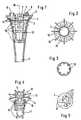
Die Erfindung wird im folgenden näher unter Bezugnahme aufdie Zeichnung erläutert, die ein vorteilhaftes Ausführungsbeispielveranschaulicht. Es zeigen:
- Fig. 1
- einen Längsschnitt durch einen Mischer in vergrößertemMaßstab;
- Fig. 2
- eine Draufsicht auf den Rotor mit mehreren Kammern;
- Fig. 3
- einen Schnitt durch das Mischrohr in Höhe desmischflügelfreien Bereichs;
- Fig. 4
- eine isometrische Ansicht des Rotors;
- Fig. 5
- eine Draufsicht auf die Stirnwand aus der Richtungder Auslaßöffnung.
- Fig. 1
- a longitudinal section through a mixer on an enlarged scale;
- Fig. 2
- a plan view of the rotor with several chambers;
- Fig. 3
- a section through the mixing tube at the level of the mixing blade-free area;
- Fig. 4
- an isometric view of the rotor;
- Fig. 5
- a plan view of the end wall from the direction of the outlet opening.
Der Mischer umfaßt ein Mischrohr 1, das an seinem einen Endeauf eine Stirnwand 2 stößt und an seinem anderen Ende eineAuslaßöffnung 6 aufweist. Weiter umfaßt der Mischer einen Rotor4, dessen Drehachse 19 mit der Längsachse des Mischrohrs1 zusammenfällt. Der Raum zwischen dem Rotor 4 und dem Mischrohr 1 bildet einen Mischkanal 3 mit ringförmigem Querschnitt.Die Stirnwand 2 weist eine Lagerbuchse 5 für einenRotorzapfen 7 auf, der mit einem beispielsweise als Innensechskantausgebildeten Kupplungsansatz herausragt.The mixer comprises a
An der Stirnwand 2 sind zwei Einlaßstutzen angeordnet, diedicht mit nicht gezeigten Auslaßstutzen des Ausbringgerätsverbunden werden können. Auf der dem Rotor 4 zugewandten Innenseiteder Stirnwand 2 bilden sie zwei Einlaßöffnungen 9,durch die die zu mischenden Komponenten in den Mischer gelangen.Auf der Innenseite der Stirnwand 2 sind sogenannte Schikanen11 angeordnet (in Fig. 1 nicht gezeigt), bei denen essich um längliche, teils gerade, teils gebogene Vorsprüngehandelt. Sie sind in der Weise angeordnet, daß sie die Einlaßöffnungen9 voneinander abschirmen. Dadurch soll bewirktwerden, daß die Komponenten nicht bereits in der Nähe derEinlaßöffnungen 9 zusammen kommen und dort aushärten können.An einer der Einlaßöffnungen 9, die kleiner als die andereausgebildet ist, sind die Schikanen so angeordnet, daß siediese Öffnungen ganz oder teilweise umschließen, beispielsweisein U-Form. Dadurch wird der Strang der durch diese Einlaßöffnung9 tretenden Komponente aufgeweitet.On the
Der Rotor 4 trägt im Anschluß an die Stirnwand 2 bzw. dieSchikanen 11 Kammern 12. Diese werden auf ihrer der Stirnwand2 abgewandten Seite von einer Platte 13 begrenzt. Auf der derStirnwand 2 zugewandten Seite der Platte 13 sitzen acht Wände14 auf, die gleichmäßig über den Kreisumfang verteilt sindund sich jeweils von der Oberfläche der Rotorwelle 7 bis zurInnenfläche des Mischrohrs 1 erstrecken und so die Kammernvoneinander trennen.The rotor 4 carries the
Die Drehbewegung des Rotors 4 erzeugt in Zusammenwirken mitder Stirnwand 2 bzw. den Schikanen 11 eine breitflächige Zusammenführungder Komponenten. Auf diese Weise werden dieKammern 12 abwechselnd mit den Komponenten gefüllt. Dabeikann die gleichmäßige Verteilung der Komponenten in den Kammern von der Aufweitung des dünneren Strangs an der kleinerenEinlaßöffnung 9 begünstigt werden. Der Inhalt der Kammernwird anschließend durch acht Ausschnitte 15, die Ausströmöffnungenbilden, in den Mischkanal 3 gepreßt.The rotary movement of the rotor 4 produces in cooperation withthe
Die Ausschnitte 15 sind als radial angeordnete, länglicheSchlitze ausgeführt, die sich jeweils von der Oberfläche derRotorwelle 7 bis zur Außenkante der Platte 13 erstrecken.Zwischen je zwei Wänden 14 befindet sich ein Ausschnitt 15.The
Im Mischkanal 3 wird die Masse durch Mischflügel 16, die invier Gruppen am Rotor 4 angeordnet sind, verrührt. Zwischender dritten und vierten Gruppe von Mischflügeln 16 befindetsich ein Bereich 17, in dem der Rotor 4 frei von Mischflügelnist. In diesem Bereich besorgen an der Innenfläche des Mischrohrs1 angeordnete, stehende Mischflügel 18 die Mischung.Nachdem die Mischung die letzte Gruppe der Mischflügel 16passiert hat, verläßt sie durch die Auslaßöffnung 6 denMischkanal 3. Der Rotor kann in einer Zweibackenform mit Anspritzplattegeformt werden, indem die Backen die Mischflügelund die Unterseite der Platte bilden, während die Kammern vonder Anspritzplatte geformt werden.In the mixing channel 3, the mass by mixing
Claims (14)
- Dynamic mixer, in particular for the components of dentalimpression pastes, one end of which can be connected to adischarge device for the components and the other end ofwhich has an outlet opening (19) for the mixture and whichcomprises a mixing tube (1), a rotor (4), which defines themixing duct (3) of an annular cross section and has mixingblades (14, 16), as well as an end wall (2) with inletopenings (9) for the components,characterised in that therotor (4) turns the open sides of a plurality of chambers(12) towards the end wall (2), which chambers are defined ontheir side remote from the end wall (2) by a plate (13) andin each case have at least one narrowed outflow opening(15).
- Dynamic mixer according to Claim 1,characterised in thatthe outflow opening(s) is/are formed by cutouts (15) in theplate (13).
- Dynamic mixer according to Claim 2,characterised in thatthe cutouts (15) are in the form of radially disposed slots.
- Dynamic mixer according to Claim 3,characterised in thatthe cutouts (15) are in the form of circular openings.
- Dynamic mixer according to any one of Claims 1 to 4,characterised in that the spacings of groups of mixingblades (16), which are in each case located at the sameheight on the rotational axis (19) of the rotor, vary alongthe rotational axis (19).
- Dynamic mixer according to any one of Claims 1 to 5,characterised in that a plurality of chambers (12)distributed over the circumference are separated by walls(14).
- Dynamic mixer according to any one of Claims 1 to 6,characterised in that the total area of the outflow openingsin relation to the cross-sectional area of the mixing duct(3) is 10 to 50%.
- Dynamic mixer according to Claim 7,characterised in thatthe total area of the outflow openings in relation to thecross-sectional area of the mixing duct (3) is 25%.
- Dynamic mixer according to any one of Claims 1 to 8,characterised in that a longitudinal proportion of at least10% of the region (17) of the rotor (4) below the chambersis free of mixing blades.
- Dynamic mixer according to Claim 9,characterised inthat upright mixing blades (18) are disposed at the innersurface of the mixing tube (1) in the region (17) of thelongitudinal proportion of the rotor (4) which is free ofmixing blades.
- Dynamic mixer according to any one of Claims 1 to 10,characterised in that baffles (11) are disposed on the sideof the end wall (2) which faces the chamber or chambers(12).
- Dynamic mixer according to Claim 11,characterised inthat all or several of the baffles (11) enclose at least oneof the inlet openings (9) entirely or partly.
- Use of a dynamic mixer according to any one of Claims 1to 12 for mixing dental materials.
- Use of a dynamic mixer according to Claim 13 for mixingmoulding materials.
Priority Applications (3)
| Application Number | Priority Date | Filing Date | Title |
|---|---|---|---|
| DE59904983TDE59904983D1 (en) | 1999-12-23 | 1999-12-23 | Dynamic mixer for dental impression materials |
| EP99125804AEP1110599B1 (en) | 1999-12-23 | 1999-12-23 | Dynamic mixer for dental impression pastes |
| US09/747,147US6540395B2 (en) | 1999-12-23 | 2000-12-22 | Dynamic mixer for dental impression compounds |
Applications Claiming Priority (1)
| Application Number | Priority Date | Filing Date | Title |
|---|---|---|---|
| EP99125804AEP1110599B1 (en) | 1999-12-23 | 1999-12-23 | Dynamic mixer for dental impression pastes |
Publications (2)
| Publication Number | Publication Date |
|---|---|
| EP1110599A1 EP1110599A1 (en) | 2001-06-27 |
| EP1110599B1true EP1110599B1 (en) | 2003-04-09 |
Family
ID=8239722
Family Applications (1)
| Application Number | Title | Priority Date | Filing Date |
|---|---|---|---|
| EP99125804AExpired - LifetimeEP1110599B1 (en) | 1999-12-23 | 1999-12-23 | Dynamic mixer for dental impression pastes |
Country Status (3)
| Country | Link |
|---|---|
| US (1) | US6540395B2 (en) |
| EP (1) | EP1110599B1 (en) |
| DE (1) | DE59904983D1 (en) |
Cited By (2)
| Publication number | Priority date | Publication date | Assignee | Title |
|---|---|---|---|---|
| US7287898B2 (en) | 2001-03-15 | 2007-10-30 | 3M Espe Ag | Dynamic mixer |
| US8322909B2 (en) | 2004-09-22 | 2012-12-04 | 3M Deutschland Gmbh | Mixer for multi-component pastes, kit, and method of mixing paste components |
Families Citing this family (70)
| Publication number | Priority date | Publication date | Assignee | Title |
|---|---|---|---|---|
| EP1138396B1 (en)* | 1998-10-14 | 2005-12-28 | Kettenbach GmbH & CO. KG | Opener for opening a tubular bag comprising a pasty material |
| EP1072323B1 (en) | 1999-07-29 | 2003-09-10 | Wilhelm A. Keller | Cartridge discharge device with actuator for dynamic mixers |
| ATE273065T1 (en)* | 1999-11-12 | 2004-08-15 | Kettenbach Gmbh & Co Kg | DEVICE FOR MIXING TWO PASTY MASSES, IN PARTICULAR FOR MIXING A DENTAL IMPRESSION MATERIAL WITH A CATALYST MATERIAL |
| US6443612B1 (en)* | 1999-12-02 | 2002-09-03 | Wilhelm A. Keller | Dynamic mixer |
| DE10164385C1 (en)* | 2001-12-28 | 2003-03-06 | Kettenbach Gmbh & Co Kg | Device for mixing two paste-like substances for dental work includes first channel extending through coupling section and having first and second parts with adjoining deflection section inbetween to ensure constant mixing ratio at outlet |
| DE602004008230T2 (en)* | 2003-03-06 | 2007-12-20 | Dentsply International Inc. | DISPENSING AND MIXING TIP |
| US20100022414A1 (en) | 2008-07-18 | 2010-01-28 | Raindance Technologies, Inc. | Droplet Libraries |
| GB0307403D0 (en) | 2003-03-31 | 2003-05-07 | Medical Res Council | Selection by compartmentalised screening |
| GB0307428D0 (en) | 2003-03-31 | 2003-05-07 | Medical Res Council | Compartmentalised combinatorial chemistry |
| US20060078893A1 (en) | 2004-10-12 | 2006-04-13 | Medical Research Council | Compartmentalised combinatorial chemistry by microfluidic control |
| ATE297249T1 (en)* | 2003-08-14 | 2005-06-15 | 3M Espe Ag | MIXING ELEMENT FOR A MULTI-COMPONENT PASTE MIXER, AND MIXER WITH THIS MIXING ELEMENT |
| JP4413561B2 (en)* | 2003-09-01 | 2010-02-10 | 株式会社ジーシー | Dental impression mixing mixer |
| US20050221339A1 (en) | 2004-03-31 | 2005-10-06 | Medical Research Council Harvard University | Compartmentalised screening by microfluidic control |
| EP1588779A1 (en)* | 2004-04-19 | 2005-10-26 | 3M Espe AG | Dynamic mixer |
| USD571927S1 (en)* | 2004-09-20 | 2008-06-24 | 3M Innovative Properties Company | Red mixing tip shaft and transparent housing combination |
| EP1640060A1 (en)* | 2004-09-22 | 2006-03-29 | 3M Espe Ag | Mixer for multi-component pastes, kit, and method of mixing paste components |
| US7445372B1 (en)* | 2004-10-01 | 2008-11-04 | Access Business Group International Llc | Custom cosmetic mixer |
| US7968287B2 (en) | 2004-10-08 | 2011-06-28 | Medical Research Council Harvard University | In vitro evolution in microfluidic systems |
| DE602006011772D1 (en)* | 2005-10-07 | 2010-03-04 | Sulzer Mixpac Ag | DYNAMIC MIXER |
| US20100137163A1 (en) | 2006-01-11 | 2010-06-03 | Link Darren R | Microfluidic Devices and Methods of Use in The Formation and Control of Nanoreactors |
| ATE540750T1 (en) | 2006-05-11 | 2012-01-15 | Raindance Technologies Inc | MICROFLUIDIC DEVICE AND METHOD |
| US9562837B2 (en) | 2006-05-11 | 2017-02-07 | Raindance Technologies, Inc. | Systems for handling microfludic droplets |
| EP3536396B1 (en) | 2006-08-07 | 2022-03-30 | The President and Fellows of Harvard College | Fluorocarbon emulsion stabilizing surfactants |
| WO2008097559A2 (en) | 2007-02-06 | 2008-08-14 | Brandeis University | Manipulation of fluids and reactions in microfluidic systems |
| WO2008130623A1 (en) | 2007-04-19 | 2008-10-30 | Brandeis University | Manipulation of fluids, fluid components and reactions in microfluidic systems |
| US20080267005A1 (en)* | 2007-04-24 | 2008-10-30 | Tyco Healthcare Group Lp | Applicator system and method of use |
| US7771110B2 (en)* | 2007-09-08 | 2010-08-10 | Pac-dent International Inc. | Twisted static paste mixer with a dynamic premixing chamber |
| SG184713A1 (en)* | 2007-09-10 | 2012-10-30 | Sulzer Mixpac Ag | Dynamic mixer |
| US7731413B2 (en)* | 2008-02-20 | 2010-06-08 | Zhermack S.P.A. | Mixer for multi-components substance for dental casting |
| US8197122B2 (en)* | 2008-04-24 | 2012-06-12 | Tyco Healthcare Group Lp | Dynamic mixing applicator |
| US12038438B2 (en) | 2008-07-18 | 2024-07-16 | Bio-Rad Laboratories, Inc. | Enzyme quantification |
| EP3415235A1 (en) | 2009-03-23 | 2018-12-19 | Raindance Technologies Inc. | Manipulation of microfluidic droplets |
| USD617001S1 (en)* | 2009-04-24 | 2010-06-01 | Cho-Lun Lee | Mixer for quantitative shot device |
| WO2011042564A1 (en) | 2009-10-09 | 2011-04-14 | Universite De Strasbourg | Labelled silica-based nanomaterial with enhanced properties and uses thereof |
| EP2517025B1 (en) | 2009-12-23 | 2019-11-27 | Bio-Rad Laboratories, Inc. | Methods for reducing the exchange of molecules between droplets |
| CA2789425C (en) | 2010-02-12 | 2020-04-28 | Raindance Technologies, Inc. | Digital analyte analysis with polymerase error correction |
| US9366632B2 (en) | 2010-02-12 | 2016-06-14 | Raindance Technologies, Inc. | Digital analyte analysis |
| US9399797B2 (en) | 2010-02-12 | 2016-07-26 | Raindance Technologies, Inc. | Digital analyte analysis |
| US10351905B2 (en) | 2010-02-12 | 2019-07-16 | Bio-Rad Laboratories, Inc. | Digital analyte analysis |
| EP2399666B1 (en)* | 2010-06-22 | 2013-02-20 | 3M Innovative Properties Company | Mixer for preparing a dental material, and system comprising the same |
| EP2622103B2 (en) | 2010-09-30 | 2022-11-16 | Bio-Rad Laboratories, Inc. | Sandwich assays in droplets |
| USD696787S1 (en) | 2011-02-01 | 2013-12-31 | 3M Innovative Properties Company | Mixing element |
| USD693940S1 (en) | 2011-02-01 | 2013-11-19 | 3M Innovative Properties Company | Mixing element |
| USD695905S1 (en) | 2011-02-01 | 2013-12-17 | 3M Innovative Properties Company | Mixing element |
| WO2012109600A2 (en) | 2011-02-11 | 2012-08-16 | Raindance Technologies, Inc. | Methods for forming mixed droplets |
| EP2675819B1 (en) | 2011-02-18 | 2020-04-08 | Bio-Rad Laboratories, Inc. | Compositions and methods for molecular labeling |
| EP2714970B1 (en) | 2011-06-02 | 2017-04-19 | Raindance Technologies, Inc. | Enzyme quantification |
| US8841071B2 (en) | 2011-06-02 | 2014-09-23 | Raindance Technologies, Inc. | Sample multiplexing |
| US8658430B2 (en) | 2011-07-20 | 2014-02-25 | Raindance Technologies, Inc. | Manipulating droplet size |
| US9352488B2 (en)* | 2012-02-29 | 2016-05-31 | Charles J. Agnello | Caulking tube assembly and method for tinting caulking |
| US9855580B2 (en) | 2012-02-29 | 2018-01-02 | Charles J. Agnello | Caulking tube assembly and method for tinting caulking |
| KR101406068B1 (en)* | 2013-09-05 | 2014-06-11 | (주)디엑스엠 | Impression mixing tip |
| US11901041B2 (en) | 2013-10-04 | 2024-02-13 | Bio-Rad Laboratories, Inc. | Digital analysis of nucleic acid modification |
| DE202013009790U1 (en) | 2013-12-04 | 2015-03-05 | Mühlbauer Technology Gmbh | Dynamic mixer |
| US9944977B2 (en) | 2013-12-12 | 2018-04-17 | Raindance Technologies, Inc. | Distinguishing rare variations in a nucleic acid sequence from a sample |
| EP3090063B1 (en) | 2013-12-31 | 2019-11-06 | Bio-Rad Laboratories, Inc. | Method for detection of latent retrovirus |
| CN103976801B (en)* | 2014-05-29 | 2016-02-24 | 黄骅市康田医疗器械有限公司 | Silica gel is from mixed head |
| JP1534032S (en)* | 2014-11-28 | 2015-09-28 | ||
| JP1534033S (en)* | 2014-11-28 | 2015-09-28 | ||
| US9827539B2 (en) | 2015-07-31 | 2017-11-28 | Phillip Phung-I Ho | Dynamic mixer head |
| US10647981B1 (en) | 2015-09-08 | 2020-05-12 | Bio-Rad Laboratories, Inc. | Nucleic acid library generation methods and compositions |
| WO2017095459A1 (en)* | 2015-12-03 | 2017-06-08 | Dow Global Technologies Llc | Dynamic mixer for viscous curable materials |
| US11324673B2 (en) | 2016-11-18 | 2022-05-10 | Miraki Innovation Think Tank Llc | Cosmetic appearance of skin |
| WO2018187573A1 (en) | 2017-04-05 | 2018-10-11 | Arctic Fox Biomedical, Inc. | Point of delivery cold slurry generation |
| MX2019011996A (en) | 2017-04-05 | 2020-01-20 | Miraki Innovation Think Tank Llc | Cold slurry containment. |
| US10500342B2 (en)* | 2017-08-21 | 2019-12-10 | Miraki Innovation Think Tank Llc | Cold slurry syringe |
| DE102018106189A1 (en)* | 2018-03-16 | 2019-09-19 | Maschinenfabrik Gustav Eirich Gmbh & Co. Kg | hygiene mixer |
| EP3714968A1 (en)* | 2019-03-29 | 2020-09-30 | Sulzer Mixpac AG | Dynamic mixer, dispensing assembly and method of dispensing multi- component material from a cartridge |
| DE102019119160A1 (en)* | 2019-07-15 | 2021-01-21 | Kulzer Gmbh | Dynamic mixer with adjustable feed channels |
| EP3906994A1 (en)* | 2020-05-05 | 2021-11-10 | Sulzer Mixpac AG | Static mixer |
Family Cites Families (27)
| Publication number | Priority date | Publication date | Assignee | Title |
|---|---|---|---|---|
| US3051455A (en)* | 1960-07-25 | 1962-08-28 | Gen Electric | Mixing nozzle |
| BE625883A (en)* | 1961-12-08 | |||
| DE1486405A1 (en)* | 1965-04-15 | 1969-06-04 | H V Hardman Company Inc | Device for mixing and dispensing materials |
| US3390814A (en)* | 1965-09-24 | 1968-07-02 | Chem Dev Corp | Mixing device |
| US3570719A (en)* | 1968-07-02 | 1971-03-16 | Louis Schiff | Reagent mixing and dispensing apparatus |
| US3587982A (en)* | 1969-01-15 | 1971-06-28 | Ncr Co | Adhesive and sealant dispenser with grinding means |
| US3767085A (en)* | 1971-08-02 | 1973-10-23 | J Cannon | Mixing syringe |
| US4107793A (en)* | 1977-05-26 | 1978-08-15 | Monsanto Company | Mixer apparatus for continuously coagulating an aqueous latex and consolidating as a paste coagulum |
| DE2949369A1 (en)* | 1979-12-07 | 1981-06-11 | Hilti AG, 9494 Schaan | DEVICE FOR DELIVERING MULTI-COMPONENT DIMENSIONS |
| DE3128611C2 (en)* | 1981-07-20 | 1994-07-14 | Hilti Ag | Dosing device for multi-component masses |
| JPS59500122A (en)* | 1982-02-05 | 1984-01-26 | シユナイダ−,ハンス クラウス | Equipment for mixing dental materials |
| DE3542522C2 (en)* | 1985-12-02 | 1993-10-28 | Hilti Ag | Handheld device for mixing and dispensing two-component masses |
| DE3723517A1 (en)* | 1987-07-16 | 1989-01-26 | Licentia Gmbh | HAND-DRIVEN, MOTOR-DRIVEN ELECTRIC TOOL |
| US4951843A (en)* | 1989-08-16 | 1990-08-28 | Sealant Equipment & Engineering, Inc. | Disposable mixing chamber liner and paddle for a dynamic mixing and dispensing gun |
| DE9017323U1 (en)* | 1990-12-21 | 1992-04-16 | Thera Patent GmbH & Co KG Gesellschaft für industrielle Schutzrechte, 8031 Seefeld | Dynamic mixer |
| DE4235736C1 (en)* | 1992-10-23 | 1994-03-24 | Bergmann Franz Josef | Device for mixing and distributing paste pulp - comprises combination of static mixer with channels for the breakdown and pre-distribution of the pulp into a number of thin strands |
| JPH06226178A (en)* | 1993-04-06 | 1994-08-16 | Kenwood Corp | Bonding agent dispenser |
| JPH08187727A (en)* | 1995-01-11 | 1996-07-23 | Teijin Ltd | Thermosetting resin mixer |
| DE29705741U1 (en)* | 1997-04-01 | 1998-08-06 | Muehlbauer Ernst Kg | Dynamic mixer for dental impression materials |
| EP1138396B1 (en)* | 1998-10-14 | 2005-12-28 | Kettenbach GmbH & CO. KG | Opener for opening a tubular bag comprising a pasty material |
| DE29818499U1 (en)* | 1998-10-16 | 2000-03-02 | Espe Dental Ag | Mixer for multi-component pastes |
| DE29819661U1 (en)* | 1998-11-04 | 1999-02-25 | Kress-Elektrik GmbH & Co Elektromotorenfabrik, 72406 Bisingen | Device for squeezing and dispensing flowable multi-components |
| EP1072323B1 (en)* | 1999-07-29 | 2003-09-10 | Wilhelm A. Keller | Cartridge discharge device with actuator for dynamic mixers |
| DE19947331C2 (en)* | 1999-10-01 | 2002-02-28 | 3M Espe Ag | Dynamic mixer |
| US6443612B1 (en)* | 1999-12-02 | 2002-09-03 | Wilhelm A. Keller | Dynamic mixer |
| PT1149627E (en)* | 2000-03-29 | 2004-11-30 | Heraeus Kulzer Gmbh & Co Kg | DYNAMIC MIXER |
| DE10015133C1 (en)* | 2000-03-29 | 2001-09-27 | Heraeus Kulzer Gmbh & Co Kg | Dynamic mixer for dental materials has at least two paddles in succession at the mixer on the side towards the chamber closure which do not strip the chamber walls |
- 1999
- 1999-12-23EPEP99125804Apatent/EP1110599B1/ennot_activeExpired - Lifetime
- 1999-12-23DEDE59904983Tpatent/DE59904983D1/ennot_activeExpired - Lifetime
- 2000
- 2000-12-22USUS09/747,147patent/US6540395B2/ennot_activeExpired - Lifetime
Cited By (3)
| Publication number | Priority date | Publication date | Assignee | Title |
|---|---|---|---|---|
| US7287898B2 (en) | 2001-03-15 | 2007-10-30 | 3M Espe Ag | Dynamic mixer |
| US7674033B2 (en) | 2001-03-15 | 2010-03-09 | 3M Espe Ag | Dynamic mixer |
| US8322909B2 (en) | 2004-09-22 | 2012-12-04 | 3M Deutschland Gmbh | Mixer for multi-component pastes, kit, and method of mixing paste components |
Also Published As
| Publication number | Publication date |
|---|---|
| US6540395B2 (en) | 2003-04-01 |
| DE59904983D1 (en) | 2003-05-15 |
| US20010005338A1 (en) | 2001-06-28 |
| EP1110599A1 (en) | 2001-06-27 |
Similar Documents
| Publication | Publication Date | Title |
|---|---|---|
| EP1110599B1 (en) | Dynamic mixer for dental impression pastes | |
| EP0971787B1 (en) | Dynamic mixer for dental impression pastes | |
| DE20302987U1 (en) | Dynamic mixer, used for mixing components of dentistry compositions, comprises mixing tube, rotor delimiting annular mixing channel, and wall with inlet openings for components | |
| DE2819945C2 (en) | Device for spraying liquid | |
| EP0537450B1 (en) | Screw kneader with steady spin | |
| EP1099470A1 (en) | Device for mixing two pasty materials, especially for mixing a dental impression material with a catalyst material | |
| EP1218094B1 (en) | Dynamic mixer | |
| DE60300822T2 (en) | Mixing element for a multi-component paste mixer, and mixer with this mixing element | |
| WO2009033832A1 (en) | Dynamic mixer | |
| EP1426099A1 (en) | Static mixer | |
| EP0993863A2 (en) | Mixer for multi-component pastes | |
| EP2599540A1 (en) | Mixing element for a static mixer | |
| DE3420290C1 (en) | Static mixing part | |
| EP1149626B1 (en) | Static mixing element and static mixer and use thereof | |
| EP1002568B1 (en) | Device for mixing multi-component masses, especially for dental use | |
| EP3658265A1 (en) | Mixer | |
| DE102004051063A1 (en) | Internal mixer for kneading plastic masses | |
| DE2513577C3 (en) | Continuously working mixer for plastic materials | |
| DE3618062A1 (en) | Device for mixing pasty or gel-like components | |
| DE102017117198A1 (en) | mixer | |
| DE3539426A1 (en) | Static mixing appliance for low- and high-viscosity substances | |
| EP2258466A1 (en) | Mixing system for dual component cartridges | |
| DE29907573U1 (en) | Dynamic mixer for dental impression materials | |
| DE102004020410B4 (en) | Dynamic mixer for pseudoplastic pastes | |
| EP2288434A1 (en) | Static mixing device, and production method |
Legal Events
| Date | Code | Title | Description |
|---|---|---|---|
| PUAI | Public reference made under article 153(3) epc to a published international application that has entered the european phase | Free format text:ORIGINAL CODE: 0009012 | |
| AK | Designated contracting states | Kind code of ref document:A1 Designated state(s):CH DE FR GB LI | |
| AX | Request for extension of the european patent | Free format text:AL;LT;LV;MK;RO;SI | |
| 17P | Request for examination filed | Effective date:20011227 | |
| AKX | Designation fees paid | Free format text:CH DE FR GB LI | |
| 17Q | First examination report despatched | Effective date:20020628 | |
| GRAH | Despatch of communication of intention to grant a patent | Free format text:ORIGINAL CODE: EPIDOS IGRA | |
| RAP1 | Party data changed (applicant data changed or rights of an application transferred) | Owner name:ERNST MUEHLBAUER GMBH & CO.KG | |
| GRAH | Despatch of communication of intention to grant a patent | Free format text:ORIGINAL CODE: EPIDOS IGRA | |
| GRAA | (expected) grant | Free format text:ORIGINAL CODE: 0009210 | |
| AK | Designated contracting states | Designated state(s):CH DE FR GB LI | |
| REG | Reference to a national code | Ref country code:GB Ref legal event code:FG4D Free format text:NOT ENGLISH | |
| REG | Reference to a national code | Ref country code:CH Ref legal event code:EP | |
| REG | Reference to a national code | Ref country code:CH Ref legal event code:NV Representative=s name:TROESCH SCHEIDEGGER WERNER AG | |
| GBT | Gb: translation of ep patent filed (gb section 77(6)(a)/1977) | ||
| ET | Fr: translation filed | ||
| PLBE | No opposition filed within time limit | Free format text:ORIGINAL CODE: 0009261 | |
| STAA | Information on the status of an ep patent application or granted ep patent | Free format text:STATUS: NO OPPOSITION FILED WITHIN TIME LIMIT | |
| 26N | No opposition filed | Effective date:20040112 | |
| REG | Reference to a national code | Ref country code:FR Ref legal event code:PLFP Year of fee payment:17 | |
| REG | Reference to a national code | Ref country code:FR Ref legal event code:PLFP Year of fee payment:18 | |
| PGFP | Annual fee paid to national office [announced via postgrant information from national office to epo] | Ref country code:GB Payment date:20161222 Year of fee payment:18 | |
| PGFP | Annual fee paid to national office [announced via postgrant information from national office to epo] | Ref country code:FR Payment date:20161221 Year of fee payment:18 | |
| GBPC | Gb: european patent ceased through non-payment of renewal fee | Effective date:20171223 | |
| REG | Reference to a national code | Ref country code:FR Ref legal event code:ST Effective date:20180831 | |
| PG25 | Lapsed in a contracting state [announced via postgrant information from national office to epo] | Ref country code:FR Free format text:LAPSE BECAUSE OF NON-PAYMENT OF DUE FEES Effective date:20180102 | |
| PG25 | Lapsed in a contracting state [announced via postgrant information from national office to epo] | Ref country code:GB Free format text:LAPSE BECAUSE OF NON-PAYMENT OF DUE FEES Effective date:20171223 | |
| PGFP | Annual fee paid to national office [announced via postgrant information from national office to epo] | Ref country code:CH Payment date:20181219 Year of fee payment:20 | |
| PGFP | Annual fee paid to national office [announced via postgrant information from national office to epo] | Ref country code:DE Payment date:20190220 Year of fee payment:20 | |
| REG | Reference to a national code | Ref country code:DE Ref legal event code:R071 Ref document number:59904983 Country of ref document:DE | |
| REG | Reference to a national code | Ref country code:CH Ref legal event code:PL |