EP1110174B1 - Contactless access ticket and method for making same - Google Patents
Contactless access ticket and method for making sameDownload PDFInfo
- Publication number
- EP1110174B1 EP1110174B1EP00949666AEP00949666AEP1110174B1EP 1110174 B1EP1110174 B1EP 1110174B1EP 00949666 AEP00949666 AEP 00949666AEP 00949666 AEP00949666 AEP 00949666AEP 1110174 B1EP1110174 B1EP 1110174B1
- Authority
- EP
- European Patent Office
- Prior art keywords
- ticket
- antenna
- protective coating
- paper
- integrated circuit
- Prior art date
- Legal status (The legal status is an assumption and is not a legal conclusion. Google has not performed a legal analysis and makes no representation as to the accuracy of the status listed.)
- Expired - Lifetime
Links
Images


Classifications
- G—PHYSICS
- G06—COMPUTING OR CALCULATING; COUNTING
- G06K—GRAPHICAL DATA READING; PRESENTATION OF DATA; RECORD CARRIERS; HANDLING RECORD CARRIERS
- G06K19/00—Record carriers for use with machines and with at least a part designed to carry digital markings
- G06K19/06—Record carriers for use with machines and with at least a part designed to carry digital markings characterised by the kind of the digital marking, e.g. shape, nature, code
- G06K19/067—Record carriers with conductive marks, printed circuits or semiconductor circuit elements, e.g. credit or identity cards also with resonating or responding marks without active components
- G06K19/07—Record carriers with conductive marks, printed circuits or semiconductor circuit elements, e.g. credit or identity cards also with resonating or responding marks without active components with integrated circuit chips
- G06K19/077—Constructional details, e.g. mounting of circuits in the carrier
- G06K19/07718—Constructional details, e.g. mounting of circuits in the carrier the record carrier being manufactured in a continuous process, e.g. using endless rolls
- G—PHYSICS
- G06—COMPUTING OR CALCULATING; COUNTING
- G06K—GRAPHICAL DATA READING; PRESENTATION OF DATA; RECORD CARRIERS; HANDLING RECORD CARRIERS
- G06K19/00—Record carriers for use with machines and with at least a part designed to carry digital markings
- G06K19/06—Record carriers for use with machines and with at least a part designed to carry digital markings characterised by the kind of the digital marking, e.g. shape, nature, code
- G06K19/067—Record carriers with conductive marks, printed circuits or semiconductor circuit elements, e.g. credit or identity cards also with resonating or responding marks without active components
- G06K19/07—Record carriers with conductive marks, printed circuits or semiconductor circuit elements, e.g. credit or identity cards also with resonating or responding marks without active components with integrated circuit chips
- G06K19/077—Constructional details, e.g. mounting of circuits in the carrier
- G06K19/07749—Constructional details, e.g. mounting of circuits in the carrier the record carrier being capable of non-contact communication, e.g. constructional details of the antenna of a non-contact smart card
- Y—GENERAL TAGGING OF NEW TECHNOLOGICAL DEVELOPMENTS; GENERAL TAGGING OF CROSS-SECTIONAL TECHNOLOGIES SPANNING OVER SEVERAL SECTIONS OF THE IPC; TECHNICAL SUBJECTS COVERED BY FORMER USPC CROSS-REFERENCE ART COLLECTIONS [XRACs] AND DIGESTS
- Y10—TECHNICAL SUBJECTS COVERED BY FORMER USPC
- Y10T—TECHNICAL SUBJECTS COVERED BY FORMER US CLASSIFICATION
- Y10T428/00—Stock material or miscellaneous articles
- Y10T428/24—Structurally defined web or sheet [e.g., overall dimension, etc.]
- Y10T428/24802—Discontinuous or differential coating, impregnation or bond [e.g., artwork, printing, retouched photograph, etc.]
Definitions
- the present inventionrelates to access to controlled areas in which use is made of a contactless access support in the controlled area, and concerns in particular a disposable contactless ticket and its method of manufacture.
- Access devices to controlled access areassuch as public transport networks such as RATP or SNCF are increasingly using the so-called "contactless" technique as opposed to conventional contact media. These must indeed be inserted in a reader to make the contact to control the validity of the support. Over time, there is fouling of the reader's brooms which often leads to an absence of contact then obliging the user to recover several times and therefore a significant loss of time.
- the exchange of information between a contactless medium and the readeris generally effected by electromagnetic coupling at a distance between a first antenna housed in the contactless medium and a second antenna located in the reader.
- the supportis further provided with an electronic module comprising the first antenna connected to a semiconductor chip or chip which contains, inter alia, a radio-frequency (RF) part, a memory in which the information to be stored is stored.
- RFradio-frequency
- the contactless smart card in ISO formatis the most suitable solution insofar as the cost price of the card spread over all trips made over a long period will always remain low for the user. But the cost of the card becomes exorbitant compared to the cost of travel for the second group of occasional users who would be obliged to buy a card for a single trip.
- one of the aims of the inventionis to provide access support to a controlled access zone such as a public transport network in the form of a disposable ticket, which is largely biodegradable, very inexpensive but has the necessary advantages. same features as a contactless access card despite the reduced dimensions.
- a second object of the inventionis to provide a method of manufacturing a disposable contactless access ticket having the same functionality as a contactless access card despite the reduced dimensions.
- the object of the inventionis therefore a ticket making it possible to obtain access to a controlled access zone when it is presented without contact in front of an access reader to the zone, such a ticket being of Edmonson format and comprising a paper ticket body covered on both sides with a protective coating.
- the paper ticket bodyhas a through recess in which there is an electronic module comprising an integrated circuit and a antenna, the latter being formed of at least one turn obtained by printing in silkscreen ink of silver powder in a polymerizable composition before curing by heat treatment.
- Another object of the inventionis a method of manufacturing contactless tickets consisting of preparing a width or multiband of paper of a width corresponding to several widths of the ticket, making recesses crossing the width intended to receive the electronic modules of the tickets. splitting the web into a plurality of single webs each corresponding to a reel of tickets, and consecutively placing each of the first layer of protective coating and the second layer of protective coating after placing the electronic modules in the recesses.
- a cap having the same thickness as the integrated circuit and having a recess passing through the place of the integrated circuitis placed on the electronic module, and the electronic module covered with the cap is hot rolled. in order to reduce the resistance of the antenna
- An access ticket 10 to a controlled access zone such as the RATP metro networkis illustrated on the figure 1 . It comprises a ticket body 12 of format Edmonson 67mm x 30mm and an electronic module 14 comprising the electronic means necessary for a user who presents the ticket in front of the appropriate reader can obtain access to the network, for example the opening of a door with automatic opening.
- the front of the ticket body 12includes printed information such as graphics, logos (RATP), alphanumeric information, bar codes, etc.
- the ticket body represented in perspective on the figure 2is formed of a central layer of paper of a thickness of about 0.5mm and two thin layers of duplex coating or overlays 18 and 20 of paper or plastic such as polyester or polyvinylchloride. a thickness of between 0.03mm and 0.05mm. The total thickness of the ticket body is generally between 0.560mm and 0.640mm or less.
- the electronic module 14which is in a recess passing through the ticket body is sandwiched between the two layers of protective coating 18 and 20.
- This electronic moduleillustrated on the figure 3 mainly comprises a paper or plastic support having a thickness of between 0.08 mm and 0.15 mm on which there is an integrated circuit or chip 22 and an antenna 24.
- the function of the integrated circuitis to process the electromagnetic signal of a frequency of 13.56 MHz transmitted by the ticket reader and received by means of the antenna 24, and transmitting the information stored in the integrated circuit 22 and intended to control access to the controlled access area by modulating an electromagnetic signal at 847 KHz used as a carrier.
- the antenna 24is in the form of a square spiral of 19mm and having at least one turn and preferably between 6 and 10 turns, the turns being square or circular, and at both ends connected to the circuit integrated 22 by means of the connections 26 and 28. It should be noted that the inductance of the antenna 24 has a value such that it forms a resonant circuit with the input capacitor of the integrated circuit
- the manufacture of the antennais an important feature of the invention since it helps to provide a lower cost ticket.
- This productionwhich uses the technique of screen printing, consists in printing the turns of the antenna on an electrically insulating substrate serving as an antenna support, preferably made of paper, but which could be made of plastic as we have just seen. see, using an ink consisting of finely divided silver powder in a polymerizable composition and a solvent. After drying and heat treatment, the conductive spiral shown in FIG. figure 3 formed of silver in a polymerized compound. Then a dielectric ink layer is printed perpendicular to the turns.
- a printis printed conductive strip 27 which is connected to the end 29 of the antenna and to the connection terminal 28 which serves to provide the electrical connection with the integrated circuit, the other connection being made using the terminal 26.
- the width of the conductor forming the antenna 24the distance between the turns and the number of turns define the value of the inductance of the antenna.
- Antennascan be mass-produced using an antenna support band and performing the antenna printing operations described above repeatedly. Then we install a chip in the center of each antenna as illustrated on the figure 3 , the connection of the chip to the ends of the antenna is preferably performed using a conductive adhesive but can of course be performed by welding. We can then proceed to the cutting of the electronic modules.
- each electronic module 14comprises a support 15 on which has been screen printed an antenna 24 and on which has been installed an integrated circuit or chip 22. While the thickness of the antenna 24 is negligible, there is no even for the chip 22 which has a certain thickness.
- a cap 21, paper or plasticis installed on each module before cutting the tape or after cutting.
- This caphas a thickness slightly greater than the thickness of the chip and has a through recess 23 having dimensions slightly greater than those of the chip for the insertion of the chip into the recess.
- the modulehas an almost constant thickness (except at the thickness chip location slightly lower) thus avoiding a depression around the chip when the coating layer is installed,.
- the ticket manufacturing processbegins with the formation of a strip or multiband of ticket bodies 30 as shown in FIG. figure 5 .
- a strip of paper 32 of desired thickness and a width equal to 10 ticket widths(this width could be different) is unwound from a reel 34 and passes to a formation station 36 where the strip of paper 32 is punched so as to form holes opening on both sides and intended to receive the electronic modules, then printed duplex if necessary.
- Station 36also performs the width slit 32 in 10 width strips of a ticket which are wound on ticket reels (not shown).
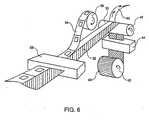
- the next step illustrated on the figure 6consists of applying layers of protective coating or overlays.
- a strip 40 made of paper or plastic (polyester, polyvinyl chloride or other plastic material) as defined aboveis used. from a coil 42 and having a width double that of the tickets so as to cover the front and back of the ticket body.
- This strip 40 coming from the spool 42is in fact formed of the overlay comprising a layer of adhesive and a thin layer of silicone paper.
- the strip 40then passes into a slot station 44 where the silicone paper is slit so as to be able to remove a strip of silicone paper 46 on half of the strip 40 after passing over a roll 48.
- the overlay of which one has removed the silicone paperthus has an adhesive side 50 while the portion of the adjacent band 52 remains protected by silicone paper.
- a band of ticket bodies 54 supplied from a spool 56is then applied to the adhesive side 50.
- the next stepis to position the electronic modules as they were made with reference to the figure 4 in the recesses of the ticket body strip.
- the maintenance of the module in its recessis provided by the layer of adhesive on the overlay strip 50.
- the electronic module with its capis independent of the rest of the ticket and does not present privileged axis of positioning. It can therefore be placed in its obviously in any way, ie in 8 possible ways. This faculty is interesting in that it does not require a meticulous method of positioning the modules and therefore expensive.
- fixing the module by gluingis not essential,
- the contactless access ticketthat has just been described above has several significant advantages. First, it has a low cost in that it uses an inexpensive manufacturing process and uses materials that significantly reduce its cost compared to the contactless card while it has the same features as this last. Then, it is biodegradable since using a paper support and this is essential since it is a disposable ticket generally after the first use.
Landscapes
- Engineering & Computer Science (AREA)
- Computer Hardware Design (AREA)
- Microelectronics & Electronic Packaging (AREA)
- Physics & Mathematics (AREA)
- General Physics & Mathematics (AREA)
- Theoretical Computer Science (AREA)
- Credit Cards Or The Like (AREA)
- Devices For Checking Fares Or Tickets At Control Points (AREA)
- Management, Administration, Business Operations System, And Electronic Commerce (AREA)
- Multi-Process Working Machines And Systems (AREA)
- Adornments (AREA)
- Ticket-Dispensing Machines (AREA)
Abstract
Description
Translated fromFrenchLa présente invention concerne les accès à des zones contrôlées dans lesquelles il est fait usage d'un support d'accès sans contact dans la zone contrôlée, et concerne en particulier un ticket sans contact jetable et son procédé de fabrication.The present invention relates to access to controlled areas in which use is made of a contactless access support in the controlled area, and concerns in particular a disposable contactless ticket and its method of manufacture.
Les supports d'accès à des zones à accès contrôlé telles que les réseaux de transport public comme la RATP ou la SNCF utilisent de plus en plus la technique dite « sans contact » par opposition aux supports classiques avec contact. Ces derniers doivent en effet être insérés dans un lecteur pour réaliser le contact permettant de contrôler la validité du support. Avec le temps, il y a encrassement des balais du lecteur qui entraîne souvent une absence de contact obligeant alors l'usager à s'y reprendre plusieurs fois et donc une perte de temps non négligeable.Access devices to controlled access areas such as public transport networks such as RATP or SNCF are increasingly using the so-called "contactless" technique as opposed to conventional contact media. These must indeed be inserted in a reader to make the contact to control the validity of the support. Over time, there is fouling of the reader's brooms which often leads to an absence of contact then obliging the user to recover several times and therefore a significant loss of time.
L'échange d'informations entre un support sans contact et le lecteur s'effectue de manière générale par couplage électromagnétique à distance entre une première antenne logée dans le support sans contact et une deuxième antenne située dans le lecteur. Le support est muni par ailleurs, d'un module électronique comportant la première antenne connectée à une pastille semi-conductrice ou puce qui contient, entre autres, une partie radio-fréquence (RF), une mémoire dans laquelle sont stockées les informations à fournir au lecteur et les fonctions logiques nécessaires pour élaborer les informations à émettre et traiter les informations reçues.The exchange of information between a contactless medium and the reader is generally effected by electromagnetic coupling at a distance between a first antenna housed in the contactless medium and a second antenna located in the reader. The support is further provided with an electronic module comprising the first antenna connected to a semiconductor chip or chip which contains, inter alia, a radio-frequency (RF) part, a memory in which the information to be stored is stored. to the reader and the logical functions necessary to elaborate the information to be transmitted and to process the information received.
I1 existe en fait deux groupes d'usagers d'un réseau de transport, les usagers permanents et les usagers occasionnels. Pour le premier groupe, la carte à puce sans contact au format ISO est la solution la plus adaptée dans la mesure où le prix de revient de la carte réparti sur la totalité des voyages effectués sur une longue période restera toujours faible pour l'usager. Mais le prix de revient de la carte devient exorbitant par rapport au coût du voyage pour le deuxième groupe composé d'usagers occasionnels qui seraient dans l'obligation d'acheter une carte pour un seul voyage.There are in fact two groups of users of a transport network, permanent users and occasional users. For the first group, the contactless smart card in ISO format is the most suitable solution insofar as the cost price of the card spread over all trips made over a long period will always remain low for the user. But the cost of the card becomes exorbitant compared to the cost of travel for the second group of occasional users who would be obliged to buy a card for a single trip.
On connait du document
C'est pourquoi un des buts de l'invention est de fournir un support d'accès à une zone à accès contrôlé telle qu'un réseau de transport public sous forme d'un ticket jetable, largement biodégradable, très peu coûteux mais possédant les mêmes fonctionnalités qu'une carte d'accès sans contact malgré les dimensions réduites.Therefore, one of the aims of the invention is to provide access support to a controlled access zone such as a public transport network in the form of a disposable ticket, which is largely biodegradable, very inexpensive but has the necessary advantages. same features as a contactless access card despite the reduced dimensions.
Un deuxième but de l'invention est de réaliser un procédé de fabrication d'un ticket d'accès sans contact jetable possédant les mêmes fonctionnalités qu'une carte d'accès sans contact malgré les dimensions réduites.A second object of the invention is to provide a method of manufacturing a disposable contactless access ticket having the same functionality as a contactless access card despite the reduced dimensions.
L'objet de l'invention est donc un ticket permettant d'obtenir l'accès à une zone à accès contrôlé lorsqu'il est présenté sans contact devant un lecteur d'accès à la zone, un tel ticket étant de format Edmonson et comprenant un corps de ticket en papier recouvert sur ses deux faces d'un revêtement de protection. Le corps de ticket en papier dispose d'un évidement traversant dans lequel se trouve un module électronique comprenant un circuit intégré et une antenne, cette dernière étant formée d'au moins une spire obtenue par impression à l'encre sérigraphique de poudre d'argent dans une composition polymérisable avant durcissement par traitement thermique.The object of the invention is therefore a ticket making it possible to obtain access to a controlled access zone when it is presented without contact in front of an access reader to the zone, such a ticket being of Edmonson format and comprising a paper ticket body covered on both sides with a protective coating. The paper ticket body has a through recess in which there is an electronic module comprising an integrated circuit and a antenna, the latter being formed of at least one turn obtained by printing in silkscreen ink of silver powder in a polymerizable composition before curing by heat treatment.
Un autre objet de l'invention est un procédé de fabrication de tickets sans contact consistant à préparer une laize ou multibande en papier d'une largeur correspondant à plusieurs largeurs de ticket, faire des évidements traversant la laize destinés à recevoir les modules électroniques des tickets, fendre la laize en plusieurs bandes simples correspondant chacune à une bobine de tickets, et placer consécutivement de chaque cela première couche de revêtement de protection puis la deuxième couche de revêtement de protection après avoir placé les modules électroniques dans les évidements.Another object of the invention is a method of manufacturing contactless tickets consisting of preparing a width or multiband of paper of a width corresponding to several widths of the ticket, making recesses crossing the width intended to receive the electronic modules of the tickets. splitting the web into a plurality of single webs each corresponding to a reel of tickets, and consecutively placing each of the first layer of protective coating and the second layer of protective coating after placing the electronic modules in the recesses.
Selon une caractéristique de l'invention, une coiffe ayant la même épaisseur que le circuit intégré et comportant un évidement traversant à l'endroit du circuit intégré, est placée sur le module électronique, et le module électronique recouvert de la coiffe est laminé à chaud de manière à réduire la résistance de l'antenneAccording to one characteristic of the invention, a cap having the same thickness as the integrated circuit and having a recess passing through the place of the integrated circuit, is placed on the electronic module, and the electronic module covered with the cap is hot rolled. in order to reduce the resistance of the antenna
Les buts, objets et autres caractéristiques de l'invention apparaîtront plus clairement à la lecture de la description détaillée qui suit en référence aux dessins joints dans lesquels :
- la
figure 1 représente la face imprimée d'un ticket d'accès à un réseau de transport public selon l'invention - la
figure 2 représente schématiquement une vue en perspective d'un ticket d'accès selon l'invention, - la
figure 3 représente le module électronique, incorporé dans le ticket d'accès selon l'invention, - la
figure 4 représente le module électronique vu en perspective lorsque la coiffe est installée sur ledit module, - la
figure 5 représente schématiquement l'étape de formation de la multibande de corps de ticket conformément au procédé selon l'invention, et - la
figure 6 représente schématiquement l'étape de formation d'une bande de tickets munie des bandes de revêtement de protection selon le procédé de l'invention.
- the
figure 1 represents the printed side of an access ticket to a public transport network according to the invention - the
figure 2 schematically represents a perspective view of an access ticket according to the invention, - the
figure 3 represents the electronic module, incorporated in the access ticket according to the invention, - the
figure 4 represents the electronic module viewed in perspective when the cap is installed on said module, - the
figure 5 schematically represents the step of forming the ticket body multiband according to the method according to the invention, and - the
figure 6 schematically represents the step of forming a band of tickets provided with protective coating strips according to the method of the invention.
Un ticket d'accès 10 à une zone à accès contrôlé telle que le réseau de métro RATP est illustré sur la
Le corps de ticket représenté en perspective sur la
Le module électronique 14 qui se trouve dans un évidement traversant du corps de ticket est placé en sandwich entre les deux couches de revêtement de protection 18 et 20.The
Ce module électronique, illustré sur la
L'antenne 24 se présente sous forme d'une spirale carrée de 19mm de côté et comportant au moins une spire et de préférence entre 6 et 10 spires, les spires pouvant être de forme carrée ou circulaire, et a ses deux extrémités connectées au circuit intégré 22 au moyen des connexions 26 et 28. On doit noter que l'inductance de l'antenne 24 a une valeur telle qu'elle forme un circuit résonnant avec le condensateur d'entrée du circuit intégréThe
La fabrication de l'antenne constitue une caractéristique importante de l'invention puisqu'elle contribue à fournir un ticket de moindre coût. Cette fabrication qui fait appel à la technique de l'impression sérigraphique consiste à imprimer les spires de l'antenne sur un substrat électriquement isolant servant de support d'antenne, de préférence en papier mais qui pourrait être en matière plastique comme on vient de le voir, à l'aide d'une encre constituée de poudre d'argent finement divisé dans une composition polymérisable et un solvant. Après séchage et traitement thermique on obtient la spirale conductrice représentée sur la
Les antennes peuvent être fabriquées en série en utilisant une bande de support d'antenne et en effectuant les opérations d'impression de l'antenne décrites ci-dessus de façon répétitive. Puis on installe une puce au centre de chaque antenne de la façon illustrée sur la
Cependant, une opération importante est réalisée dans le cadre de la présente invention de préférence avant le découpage du module électronique. Si on se réfère à la
Enfin, une opération essentielle dans le cadre de l'invention est réalisée. Il s'agit d'une lamination à chaud qui permet d'améliorer considérablement les caractéristiques de l'antenne. Il est en effet primordial de réduire le plus possible la résistance de l'antenne de manière à ce qu'une intensité la plus importante possible circule dans l'antenne de façon à obtenir la plus grande puissance d'émission possible à l'aide de l'inductance de l'antenne. Il a été constaté que cette réduction de résistance est obtenue en appliquant une pression comprise entre 20 et 120 kg/cm2 et principalement en appliquant une température qui est comprise de préférence entre 80° et 170°C, ce qui est réalisé par l'opération de lamination à chaud.Finally, an essential operation in the context of the invention is carried out. This is a hot lamination that significantly improves the characteristics of the antenna. It is indeed essential to reduce the resistance of the antenna as much as possible so that as much intensity as possible circulates in the antenna so as to obtain the greatest possible transmission power with the aid of the inductance of the antenna. It has been found that this reduction in resistance is obtained by applying a pressure of between 20 and 120 kg / cm2 and mainly by applying a temperature which is preferably between 80 ° and 170 ° C., which is achieved by the hot lamination operation.
Le procédé de fabrication des tickets commence par la formation d'une laize ou multibande de corps de tickets 30 comme illustré sur la
L'étape suivante illustrée sur la
La bande 40 passe ensuite dans une station de fente 44 ou on procède à la fente du papier siliconé de façon à pouvoir retirer une bande de papier siliconé 46 sur la moitié de la bande 40 après passage sur un rouleau 48. L'overlay dont on a retiré le papier siliconé présente donc une face adhésivée 50 alors que la partie de la bande adjacente 52 reste protégée par du papier siliconé. Une bande de corps de tickets 54 fournie à partir d'une bobine 56 est alors appliquée sur la face adhésivée 50.The
L'opération suivante consiste à positionner les modules électroniques tels qu'ils ont été fabriqués en référence à la
Enfin, la partie de l'overlay non découverte 52 est rabattue sur la bande de corps de tickets 54 après que le revêtement de papier siliconé a été retiré.Finally, the undiscovered portion of the
On doit noter, que bien que le procédé qui vient d'être décrit soit utilisé de préférence, il est possible d'utiliser deux bandes séparées comme couches de revêtement de protection plutôt qu'une seule bande que l'on replie sur la bande de tickets. En outre, on pourrait également utiliser un procédé de collage des overlays sur le corps du ticket par lamination à chaud plutôt que d'utiliser un collage par simple adhésif.It should be noted that although the method just described is preferably used, it is possible to use two separate strips as coating layers. rather than a single tape that folds over the ticket strip. In addition, one could also use a method of bonding overlays on the body of the ticket by hot lamination rather than using a simple adhesive bonding.
Le ticket d'accès sans contact qui vient d'être décrit ci-dessus présente plusieurs avantages significatifs. Tout d'abord, il présente un faible coût de revient dans la mesure où il fait appel à un procédé de fabrication peu coûteux et utilise des matériaux réduisant considérablement son coût comparativement à la carte sans contact alors qu'il présente les mêmes fonctionnalités que cette dernière. Ensuite, il est biodégradable puisqu'utilisant un support en papier et ceci est primordial puisqu'il s'agit d'un ticket jetable généralement après la première utilisation.The contactless access ticket that has just been described above has several significant advantages. First, it has a low cost in that it uses an inexpensive manufacturing process and uses materials that significantly reduce its cost compared to the contactless card while it has the same features as this last. Then, it is biodegradable since using a paper support and this is essential since it is a disposable ticket generally after the first use.
Claims (8)
- A ticket (10) providing access to a zone with controlled access when it is presented without contact in front of a ticket reader authorizing access to the zone, said ticket having an Edmonson format and comprising a paper ticket body (12) covered on both surfaces with a protective coating (18, 20), said paper ticket body being provided with a recess wherein is located an electronic module (14) comprising an integrated circuit (22) and an antenna (24), said antenna being formed by at least one turn obtained by screen printing with silvery powder in a polymerisable composition before being heat-cured;
said ticket beingcharacterized in that said electronic module includes an overlay (21) featuring a hole in which said integrated circuit is located so that said module has a constant thickness at either the location of said integrated circuit (22) or on the outside. - The ticket according to claim 1 in which said antenna (24) is made up of a number of turns between 6 and 10.
- The ticket according to claim 1 or 2 in which said antenna (24) is formed by one or more square turns.
- The ticket according to claim 1, 2, or 3 in which said electronic module (14) is comprised of a paper support (15) on which the antenna is obtained by screen printing and said integrated circuit (22) is fixed between the ends of said antenna by soldering or bonding by means of a conductive adhesive.
- A fabrication process of ticket according to claim 1 to 4,characterized in that it consists in:a) preparing a paper strip (30) or multi-band having a width corresponding to several ticket widths,b) making holes which pass through said strip designed to receive the electronic modules of said tickets,c) slitting said strip into several single strips (54) each corresponding to one reel of tickets (56), andd) placing consecutively, on each side of said strip with said holes, the first layer of protective coating, then the second layer of protective coating after having inserted the electronic modules in said holes, step d) consists in:d1) preparing a first protective coating strip (50) having an adhesive on one side covered by backing paper,d2) removing said backing paper (46) so as to uncover the adhesive face,d3) bonding said single band (54) corresponding to a reel of tickets and arranging said holes, on said adhesive face,d4) placing said electronic modules in said holes, said electronic modules being maintained in the holes by the adhesive of said first layer of protective coating, andd5) covering said band bonded to said first layer of protective coating with a second layer of protective coating (52) having an adhesive face.
- The process according to claim 5 in which both layers of protective coating initially form a single band (40) measuring the double width of said single band corresponding to a reel of tickets and having an adhesive face covered with backing paper, a band of backing paper (46) being initially removed from the part which will form the first layer of protective coating to affix said single band (54) and the backing paper then being entirely removed from said double width band so that it can be folded over and bonded onto said single band and to serve as a second layer of protective coating for the latter after the electronic modules have been placed in said holes.
- The process according to claim 5 or 6, also including the following fabrication steps for electronic modules prior to placing the latter into said holes in step c) :C1) screen printing of said antenna (24) on a paper support (15),C2) placing said integrated circuit (22) on said paper support while connecting it between the ends of said antenna by bonding or soldering,C3) installing an overlay (21) onto said module, said overlay having the same thickness as said integrated circuit and featuring a through-hole at the location of said integrated circuit, andC4) proceeding with the hot lamination of said electronic module covered by said overlay so as to reduce the resistance of said antenna.
- The process according to claim 7 in which the hot lamination step is performed at a pressure between 20 and 120 kg/cm3 and at a temperature between 80 and 170°C.
Applications Claiming Priority (3)
| Application Number | Priority Date | Filing Date | Title |
|---|---|---|---|
| FR9908802AFR2796183B1 (en) | 1999-07-07 | 1999-07-07 | CONTACTLESS ACCESS TICKET AND MANUFACTURING METHOD THEREOF |
| FR9908802 | 1999-07-07 | ||
| PCT/FR2000/001959WO2001004834A1 (en) | 1999-07-07 | 2000-07-07 | Contactless access ticket and method for making same |
Publications (2)
| Publication Number | Publication Date |
|---|---|
| EP1110174A1 EP1110174A1 (en) | 2001-06-27 |
| EP1110174B1true EP1110174B1 (en) | 2008-11-05 |
Family
ID=9547829
Family Applications (1)
| Application Number | Title | Priority Date | Filing Date |
|---|---|---|---|
| EP00949666AExpired - LifetimeEP1110174B1 (en) | 1999-07-07 | 2000-07-07 | Contactless access ticket and method for making same |
Country Status (22)
| Country | Link |
|---|---|
| US (1) | US6497371B2 (en) |
| EP (1) | EP1110174B1 (en) |
| JP (1) | JP2003504766A (en) |
| KR (1) | KR100742660B1 (en) |
| CN (1) | CN1204528C (en) |
| AT (1) | ATE413664T1 (en) |
| AU (1) | AU775727B2 (en) |
| BR (1) | BR0006901A (en) |
| CA (1) | CA2342718A1 (en) |
| DE (1) | DE60040717D1 (en) |
| ES (1) | ES2316377T3 (en) |
| FR (1) | FR2796183B1 (en) |
| HK (1) | HK1042574B (en) |
| ID (1) | ID28902A (en) |
| IL (2) | IL141761A0 (en) |
| NO (1) | NO20011169L (en) |
| NZ (1) | NZ510780A (en) |
| PT (1) | PT1110174E (en) |
| RU (1) | RU2251741C2 (en) |
| TR (1) | TR200100704T1 (en) |
| WO (1) | WO2001004834A1 (en) |
| ZA (1) | ZA200101649B (en) |
Families Citing this family (72)
| Publication number | Priority date | Publication date | Assignee | Title |
|---|---|---|---|---|
| US6963859B2 (en) | 1994-11-23 | 2005-11-08 | Contentguard Holdings, Inc. | Content rendering repository |
| JPH08263438A (en)* | 1994-11-23 | 1996-10-11 | Xerox Corp | Distribution and use control system of digital work and access control method to digital work |
| US6233684B1 (en) | 1997-02-28 | 2001-05-15 | Contenaguard Holdings, Inc. | System for controlling the distribution and use of rendered digital works through watermaking |
| FI112288B (en)* | 2000-01-17 | 2003-11-14 | Rafsec Oy | Procedure for producing an input path for smart labels |
| FI111881B (en)* | 2000-06-06 | 2003-09-30 | Rafsec Oy | Intelligent card path and process for its manufacture |
| US7743259B2 (en)* | 2000-08-28 | 2010-06-22 | Contentguard Holdings, Inc. | System and method for digital rights management using a standard rendering engine |
| US8225414B2 (en) | 2000-08-28 | 2012-07-17 | Contentguard Holdings, Inc. | Method and apparatus for identifying installed software and regulating access to content |
| FR2815176B1 (en)* | 2000-10-11 | 2003-01-10 | A S K | SPIRAL TRANSMISSION AND / OR RECEPTION ANTENNA WITH CUT-OFFS |
| US6901429B2 (en) | 2000-10-27 | 2005-05-31 | Eric Morgan Dowling | Negotiated wireless peripheral security systems |
| US6965914B2 (en) | 2000-10-27 | 2005-11-15 | Eric Morgan Dowling | Negotiated wireless peripheral systems |
| US7035932B1 (en) | 2000-10-27 | 2006-04-25 | Eric Morgan Dowling | Federated multiprotocol communication |
| US7343324B2 (en) | 2000-11-03 | 2008-03-11 | Contentguard Holdings Inc. | Method, system, and computer readable medium for automatically publishing content |
| FI112121B (en) | 2000-12-11 | 2003-10-31 | Rafsec Oy | Smart label web, process for making the same, method for making a carrier web and construction part for a smart label in a smart label web |
| US6912294B2 (en) | 2000-12-29 | 2005-06-28 | Contentguard Holdings, Inc. | Multi-stage watermarking process and system |
| US7774279B2 (en) | 2001-05-31 | 2010-08-10 | Contentguard Holdings, Inc. | Rights offering and granting |
| US6754642B2 (en)* | 2001-05-31 | 2004-06-22 | Contentguard Holdings, Inc. | Method and apparatus for dynamically assigning usage rights to digital works |
| US20040039704A1 (en)* | 2001-01-17 | 2004-02-26 | Contentguard Holdings, Inc. | System and method for supplying and managing usage rights of users and suppliers of items |
| US7028009B2 (en) | 2001-01-17 | 2006-04-11 | Contentguardiholdings, Inc. | Method and apparatus for distributing enforceable property rights |
| US8069116B2 (en) | 2001-01-17 | 2011-11-29 | Contentguard Holdings, Inc. | System and method for supplying and managing usage rights associated with an item repository |
| US6895503B2 (en) | 2001-05-31 | 2005-05-17 | Contentguard Holdings, Inc. | Method and apparatus for hierarchical assignment of rights to documents and documents having such rights |
| US8099364B2 (en) | 2001-05-31 | 2012-01-17 | Contentguard Holdings, Inc. | Digital rights management of content when content is a future live event |
| US8275709B2 (en) | 2001-05-31 | 2012-09-25 | Contentguard Holdings, Inc. | Digital rights management of content when content is a future live event |
| US8001053B2 (en) | 2001-05-31 | 2011-08-16 | Contentguard Holdings, Inc. | System and method for rights offering and granting using shared state variables |
| US7725401B2 (en) | 2001-05-31 | 2010-05-25 | Contentguard Holdings, Inc. | Method and apparatus for establishing usage rights for digital content to be created in the future |
| US8275716B2 (en) | 2001-05-31 | 2012-09-25 | Contentguard Holdings, Inc. | Method and system for subscription digital rights management |
| US6876984B2 (en) | 2001-05-31 | 2005-04-05 | Contentguard Holdings, Inc. | Method and apparatus for establishing usage rights for digital content to be created in the future |
| US7774280B2 (en) | 2001-06-07 | 2010-08-10 | Contentguard Holdings, Inc. | System and method for managing transfer of rights using shared state variables |
| KR20030096250A (en) | 2001-06-07 | 2003-12-24 | 콘텐트가드 홀딩즈 인코포레이티드 | Method and apparatus for supporting multiple trust zones in a digital rights management system |
| FI117331B (en) | 2001-07-04 | 2006-09-15 | Rafsec Oy | Method of manufacturing an injection molded product |
| US7150406B2 (en)* | 2001-09-18 | 2006-12-19 | Nagraid S.A. | Thin electronic label and method for making same |
| NL1019264C2 (en)* | 2001-10-31 | 2003-05-02 | Stork Screens Bv | Screen printing method for producing an electrically conductive image on a substrate. |
| US7840488B2 (en)* | 2001-11-20 | 2010-11-23 | Contentguard Holdings, Inc. | System and method for granting access to an item or permission to use an item based on configurable conditions |
| WO2003044680A1 (en)* | 2001-11-20 | 2003-05-30 | Contentguard Holdings, Inc. | Systems and methods for creating, manipulating and processing rights and contract expressions using tokenized templates |
| US7974923B2 (en)* | 2001-11-20 | 2011-07-05 | Contentguard Holdings, Inc. | Extensible rights expression processing system |
| US7805371B2 (en)* | 2002-03-14 | 2010-09-28 | Contentguard Holdings, Inc. | Rights expression profile system and method |
| EP1490819A4 (en)* | 2002-03-14 | 2006-05-31 | Contentguard Holdings Inc | SYSTEM AND METHOD FOR EXPRESSING USE RIGHTS USING MODULATED SIGNALS |
| US6851617B2 (en)* | 2002-04-19 | 2005-02-08 | Avery Dennison Corporation | Laser imageable RFID label/tag |
| US8543511B2 (en)* | 2002-04-29 | 2013-09-24 | Contentguard Holdings, Inc. | System and method for specifying and processing legality expressions |
| DE10232568A1 (en)* | 2002-07-18 | 2004-01-29 | Agfa-Gevaert Ag | identity card |
| SG106662A1 (en)* | 2002-11-15 | 2004-10-29 | Smartag S Pte Ltd | Rfid tag for an object having metallic portions, tag coupler and method thereof |
| FR2848705B1 (en)* | 2002-12-12 | 2005-04-01 | Schlumberger Systems & Service | METHOD FOR MANAGING PAY PARKING SPACES USING ELECTRONIC PARKING TITLES |
| FR2850490A1 (en)* | 2003-01-24 | 2004-07-30 | Framatome Connectors Int | Antenna e.g. for card with electronic chip or RFID label has insulating strip made with notches for conducting strip or connector |
| US7685642B2 (en)* | 2003-06-26 | 2010-03-23 | Contentguard Holdings, Inc. | System and method for controlling rights expressions by stakeholders of an item |
| DE10334578A1 (en)* | 2003-07-28 | 2005-03-10 | Infineon Technologies Ag | Chip card, chip card module and method for producing a chip card module |
| DE102004004469A1 (en)* | 2003-12-22 | 2005-08-18 | Smartrac Technology Ltd. | Production of a security layered structure for identification documents |
| US20050097593A1 (en)* | 2003-11-05 | 2005-05-05 | Michael Raley | System, method and device for selected content distribution |
| FR2864670B1 (en)* | 2003-12-29 | 2007-04-27 | A S K | METHOD FOR DISTRIBUTING AND CUSTOMIZING CONTACTLESS CHIP TICKETS AND DEVICE THEREOF |
| US7370808B2 (en)* | 2004-01-12 | 2008-05-13 | Symbol Technologies, Inc. | Method and system for manufacturing radio frequency identification tag antennas |
| CN1910600B (en)* | 2004-01-23 | 2011-12-14 | 株式会社半导体能源研究所 | ID label, ID card, and ID tag |
| US8305213B2 (en)* | 2004-01-23 | 2012-11-06 | Semiconductor Energy Laboratory Co., Ltd. | Film-like article and method for manufacturing the same |
| US7612677B2 (en) | 2005-01-28 | 2009-11-03 | Smartrac Ip B.V. | Method for producing a security layered construction and security layered construction and identification documents containing such a construction |
| US7037556B2 (en) | 2004-03-10 | 2006-05-02 | Jet Lithocolor Inc. | Process and apparatus for preparation of a no-jam vending machine plastic card |
| FR2868987B1 (en) | 2004-04-14 | 2007-02-16 | Arjo Wiggins Secutity Sas Soc | STRUCTURE COMPRISING AN ELECTRONIC DEVICE, IN PARTICULAR FOR THE MANUFACTURE OF A SECURITY OR VALUE DOCUMENT |
| US8407097B2 (en)* | 2004-04-15 | 2013-03-26 | Hand Held Products, Inc. | Proximity transaction apparatus and methods of use thereof |
| GB2419779A (en)* | 2004-10-29 | 2006-05-03 | Hewlett Packard Development Co | Document having conductive tracks for coupling to a memory tag and a reader |
| US20060107326A1 (en)* | 2004-11-12 | 2006-05-18 | Demartini Thomas | Method, system, and device for verifying authorized issuance of a rights expression |
| US20060106726A1 (en)* | 2004-11-18 | 2006-05-18 | Contentguard Holdings, Inc. | Method, system, and device for license-centric content consumption |
| US8660961B2 (en)* | 2004-11-18 | 2014-02-25 | Contentguard Holdings, Inc. | Method, system, and device for license-centric content consumption |
| US20060112015A1 (en)* | 2004-11-24 | 2006-05-25 | Contentguard Holdings, Inc. | Method, system, and device for handling creation of derivative works and for adapting rights to derivative works |
| US20060248573A1 (en)* | 2005-04-28 | 2006-11-02 | Content Guard Holdings, Inc. | System and method for developing and using trusted policy based on a social model |
| US20060273180A1 (en)* | 2005-06-06 | 2006-12-07 | Cascade Engineering, Inc. | RFID label assembly |
| US7224278B2 (en)* | 2005-10-18 | 2007-05-29 | Avery Dennison Corporation | Label with electronic components and method of making same |
| US7720767B2 (en)* | 2005-10-24 | 2010-05-18 | Contentguard Holdings, Inc. | Method and system to support dynamic rights and resources sharing |
| FR2902696A1 (en)* | 2006-06-27 | 2007-12-28 | Ask Sa | NON-CONTACT CHIP TICKET ASSEMBLY |
| US7701352B2 (en)* | 2006-11-22 | 2010-04-20 | Avery Dennison Corporation | RFID label with release liner window, and method of making |
| WO2008103870A1 (en)* | 2007-02-23 | 2008-08-28 | Newpage Wisconsin System Inc. | Multifunctional paper identification label |
| TW200912761A (en)* | 2007-07-20 | 2009-03-16 | Soon Huat Leonard Wee | A radio frequency transponder |
| FR2944121B1 (en)* | 2009-04-03 | 2016-06-24 | Paragon Identification | SEMI-RIGID RADIO FREQUENCY IDENTIFICATION CARD (RFID), THE MANUFACTURING METHOD AND THE MACHINE FOR ITS MANUFACTURE |
| EP2390825A1 (en)* | 2010-05-31 | 2011-11-30 | Gemalto SA | Method for manufacturing a device comprising a transponder antenna on a thin core and device obtained |
| RU2603837C2 (en)* | 2014-02-19 | 2016-12-10 | Геннадий Леонидович Багич | Method of making electronic card (electronic key) |
| CN110091647B (en)* | 2018-01-31 | 2022-11-11 | 上海永力信息科技股份有限公司 | Disposable intelligent entrance ticket |
| US20240412026A1 (en)* | 2021-02-09 | 2024-12-12 | Confidex Oy | An rfid identifier |
Family Cites Families (14)
| Publication number | Priority date | Publication date | Assignee | Title |
|---|---|---|---|---|
| US615285A (en)* | 1898-12-06 | Chain | ||
| US4846922A (en)* | 1986-09-29 | 1989-07-11 | Monarch Marking Systems, Inc. | Method of making deactivatable tags |
| GB9222460D0 (en)* | 1992-10-26 | 1992-12-09 | Hughes Microelectronics Europa | Radio frequency baggage tag |
| ZA941671B (en)* | 1993-03-11 | 1994-10-12 | Csir | Attaching an electronic circuit to a substrate. |
| JPH06336096A (en)* | 1993-05-28 | 1994-12-06 | Omron Corp | Card type substrate |
| DE9422424U1 (en)* | 1994-02-04 | 2002-02-21 | Giesecke & Devrient GmbH, 81677 München | Chip card with an electronic module |
| DE59502922D1 (en)* | 1994-09-30 | 1998-08-27 | Siemens Ag | SUPPORT ARRANGEMENT FOR INSTALLATION IN A CONTACTLESS CHIP CARD |
| US5662976A (en)* | 1994-10-24 | 1997-09-02 | Avery Dennison Corporation | Laminated card assembly |
| US5817207A (en)* | 1995-10-17 | 1998-10-06 | Leighton; Keith R. | Radio frequency identification card and hot lamination process for the manufacture of radio frequency identification cards |
| WO1997042598A1 (en)* | 1996-05-09 | 1997-11-13 | Atmel Corporation | Smart card formed with two joined sheets |
| DE19701167A1 (en)* | 1997-01-15 | 1998-07-23 | Siemens Ag | Smart card |
| JPH1134562A (en)* | 1997-07-17 | 1999-02-09 | Tokin Corp | Non-contact card |
| JPH1142874A (en)* | 1997-07-29 | 1999-02-16 | East Japan Railway Co | IC card ticket |
| DE19845296A1 (en)* | 1998-09-03 | 2000-03-16 | Fraunhofer Ges Forschung | Method for contacting a circuit chip |
- 1999
- 1999-07-07FRFR9908802Apatent/FR2796183B1/ennot_activeExpired - Fee Related
- 2000
- 2000-07-07IDIDW20010773Apatent/ID28902A/enunknown
- 2000-07-07ATAT00949666Tpatent/ATE413664T1/ennot_activeIP Right Cessation
- 2000-07-07CACA002342718Apatent/CA2342718A1/ennot_activeAbandoned
- 2000-07-07HKHK02102883.4Apatent/HK1042574B/ennot_activeIP Right Cessation
- 2000-07-07CNCNB00801647XApatent/CN1204528C/ennot_activeExpired - Fee Related
- 2000-07-07ILIL14176100Apatent/IL141761A0/enactiveIP Right Grant
- 2000-07-07BRBR0006901-9Apatent/BR0006901A/ennot_activeApplication Discontinuation
- 2000-07-07AUAU62952/00Apatent/AU775727B2/ennot_activeCeased
- 2000-07-07TRTR2001/00704Tpatent/TR200100704T1/enunknown
- 2000-07-07KRKR1020017002900Apatent/KR100742660B1/ennot_activeExpired - Fee Related
- 2000-07-07NZNZ510780Apatent/NZ510780A/enunknown
- 2000-07-07DEDE60040717Tpatent/DE60040717D1/ennot_activeExpired - Lifetime
- 2000-07-07WOPCT/FR2000/001959patent/WO2001004834A1/enactiveApplication Filing
- 2000-07-07PTPT00949666Tpatent/PT1110174E/enunknown
- 2000-07-07ESES00949666Tpatent/ES2316377T3/ennot_activeExpired - Lifetime
- 2000-07-07EPEP00949666Apatent/EP1110174B1/ennot_activeExpired - Lifetime
- 2000-07-07RURU2001109243/09Apatent/RU2251741C2/ennot_activeIP Right Cessation
- 2000-07-07JPJP2001510164Apatent/JP2003504766A/enactivePending
- 2001
- 2001-02-28ZAZA200101649Apatent/ZA200101649B/enunknown
- 2001-03-01ILIL141761Apatent/IL141761A/ennot_activeIP Right Cessation
- 2001-03-07USUS09/799,700patent/US6497371B2/ennot_activeExpired - Fee Related
- 2001-03-07NONO20011169Apatent/NO20011169L/ennot_activeApplication Discontinuation
Also Published As
| Publication number | Publication date |
|---|---|
| IL141761A (en) | 2007-06-03 |
| BR0006901A (en) | 2001-06-12 |
| KR100742660B1 (en) | 2007-07-25 |
| KR20010074973A (en) | 2001-08-09 |
| ATE413664T1 (en) | 2008-11-15 |
| HK1042574A1 (en) | 2002-08-16 |
| PT1110174E (en) | 2009-02-16 |
| CA2342718A1 (en) | 2001-01-18 |
| AU775727B2 (en) | 2004-08-12 |
| ZA200101649B (en) | 2001-10-01 |
| US6497371B2 (en) | 2002-12-24 |
| CN1204528C (en) | 2005-06-01 |
| NO20011169D0 (en) | 2001-03-07 |
| US20020127423A1 (en) | 2002-09-12 |
| FR2796183B1 (en) | 2001-09-28 |
| NZ510780A (en) | 2002-11-26 |
| JP2003504766A (en) | 2003-02-04 |
| DE60040717D1 (en) | 2008-12-18 |
| EP1110174A1 (en) | 2001-06-27 |
| NO20011169L (en) | 2001-05-07 |
| HK1042574B (en) | 2005-12-16 |
| WO2001004834A1 (en) | 2001-01-18 |
| ID28902A (en) | 2001-07-12 |
| TR200100704T1 (en) | 2001-09-21 |
| IL141761A0 (en) | 2002-03-10 |
| FR2796183A1 (en) | 2001-01-12 |
| RU2251741C2 (en) | 2005-05-10 |
| AU6295200A (en) | 2001-01-30 |
| CN1320247A (en) | 2001-10-31 |
| ES2316377T3 (en) | 2009-04-16 |
Similar Documents
| Publication | Publication Date | Title |
|---|---|---|
| EP1110174B1 (en) | Contactless access ticket and method for making same | |
| EP1060457B1 (en) | Electronic device with disposable chip and method for making same | |
| EP2410470B1 (en) | Microcircuit device including a means for amplifying the gain of an antenna | |
| US6073856A (en) | Noncontact IC device | |
| EP1019870B1 (en) | Method for making an electronic device with chip and antenna and device obtained by said method | |
| EP3391291B1 (en) | Radiofrequency device with adjustable lc circuit including an electric and/or electronic module | |
| EP1105839B1 (en) | Method for making a contactless chip card | |
| EP1629420B1 (en) | Method for producing a contactless ticket | |
| EP1116179B1 (en) | Contactless card comprising inhibiting means | |
| EP2545503B1 (en) | Electronic device having a chip and method for manufacturing by coils | |
| EP3899792B1 (en) | Method for manufacturing a metal radiofrequency smart card with improved electromagnetic permittivity | |
| EP1201007B1 (en) | Antenna for contactless cards, hybrid cards and electronic labels | |
| EP2021985B1 (en) | Radio frequency identification device medium and method for making same | |
| FR2950744A1 (en) | Contactless portable electronic device e.g. subscriber identity module card, for portable telephone, has mass extended partially opposite to surface to guide field lines, through surface, towards exterior of surface in absence of mass | |
| MXPA01002377A (en) | Contactless access ticket and method for making same | |
| FR3002108A1 (en) | Method for manufacturing thin carrier of radio frequency device e.g. smart card, operating in high frequency field, involves heat treating contact pads of antenna to dry polymer ink, and connecting chip or electronic module to contact pads |
Legal Events
| Date | Code | Title | Description |
|---|---|---|---|
| PUAI | Public reference made under article 153(3) epc to a published international application that has entered the european phase | Free format text:ORIGINAL CODE: 0009012 | |
| 17P | Request for examination filed | Effective date:20010404 | |
| AK | Designated contracting states | Kind code of ref document:A1 Designated state(s):AT BE CH CY DE DK ES FI FR GB GR IE IT LI LU MC NL PT SE | |
| AX | Request for extension of the european patent | Free format text:AL;LT;LV;MK;RO;SI | |
| 17Q | First examination report despatched | Effective date:20071213 | |
| GRAP | Despatch of communication of intention to grant a patent | Free format text:ORIGINAL CODE: EPIDOSNIGR1 | |
| GRAS | Grant fee paid | Free format text:ORIGINAL CODE: EPIDOSNIGR3 | |
| GRAA | (expected) grant | Free format text:ORIGINAL CODE: 0009210 | |
| AK | Designated contracting states | Kind code of ref document:B1 Designated state(s):AT BE CH CY DE DK ES FI FR GB GR IE IT LI LU MC NL PT SE | |
| REG | Reference to a national code | Ref country code:GB Ref legal event code:FG4D Free format text:NOT ENGLISH | |
| REG | Reference to a national code | Ref country code:CH Ref legal event code:EP | |
| REG | Reference to a national code | Ref country code:IE Ref legal event code:FG4D Free format text:LANGUAGE OF EP DOCUMENT: FRENCH | |
| REF | Corresponds to: | Ref document number:60040717 Country of ref document:DE Date of ref document:20081218 Kind code of ref document:P | |
| REG | Reference to a national code | Ref country code:PT Ref legal event code:SC4A Free format text:AVAILABILITY OF NATIONAL TRANSLATION Effective date:20090205 | |
| REG | Reference to a national code | Ref country code:SE Ref legal event code:TRGR | |
| REG | Reference to a national code | Ref country code:ES Ref legal event code:FG2A Ref document number:2316377 Country of ref document:ES Kind code of ref document:T3 | |
| PG25 | Lapsed in a contracting state [announced via postgrant information from national office to epo] | Ref country code:AT Free format text:LAPSE BECAUSE OF FAILURE TO SUBMIT A TRANSLATION OF THE DESCRIPTION OR TO PAY THE FEE WITHIN THE PRESCRIBED TIME-LIMIT Effective date:20081105 | |
| REG | Reference to a national code | Ref country code:IE Ref legal event code:FD4D | |
| PG25 | Lapsed in a contracting state [announced via postgrant information from national office to epo] | Ref country code:IE Free format text:LAPSE BECAUSE OF FAILURE TO SUBMIT A TRANSLATION OF THE DESCRIPTION OR TO PAY THE FEE WITHIN THE PRESCRIBED TIME-LIMIT Effective date:20081105 Ref country code:DK Free format text:LAPSE BECAUSE OF FAILURE TO SUBMIT A TRANSLATION OF THE DESCRIPTION OR TO PAY THE FEE WITHIN THE PRESCRIBED TIME-LIMIT Effective date:20081105 | |
| PLBE | No opposition filed within time limit | Free format text:ORIGINAL CODE: 0009261 | |
| STAA | Information on the status of an ep patent application or granted ep patent | Free format text:STATUS: NO OPPOSITION FILED WITHIN TIME LIMIT | |
| 26N | No opposition filed | Effective date:20090806 | |
| BERE | Be: lapsed | Owner name:ASK S.A. Effective date:20090731 | |
| PG25 | Lapsed in a contracting state [announced via postgrant information from national office to epo] | Ref country code:MC Free format text:LAPSE BECAUSE OF NON-PAYMENT OF DUE FEES Effective date:20090731 | |
| PG25 | Lapsed in a contracting state [announced via postgrant information from national office to epo] | Ref country code:BE Free format text:LAPSE BECAUSE OF NON-PAYMENT OF DUE FEES Effective date:20090731 | |
| PG25 | Lapsed in a contracting state [announced via postgrant information from national office to epo] | Ref country code:GR Free format text:LAPSE BECAUSE OF FAILURE TO SUBMIT A TRANSLATION OF THE DESCRIPTION OR TO PAY THE FEE WITHIN THE PRESCRIBED TIME-LIMIT Effective date:20090206 | |
| PG25 | Lapsed in a contracting state [announced via postgrant information from national office to epo] | Ref country code:LU Free format text:LAPSE BECAUSE OF NON-PAYMENT OF DUE FEES Effective date:20090707 | |
| PGFP | Annual fee paid to national office [announced via postgrant information from national office to epo] | Ref country code:PT Payment date:20110621 Year of fee payment:12 Ref country code:SE Payment date:20110620 Year of fee payment:12 | |
| PGFP | Annual fee paid to national office [announced via postgrant information from national office to epo] | Ref country code:NL Payment date:20110627 Year of fee payment:12 Ref country code:GB Payment date:20110627 Year of fee payment:12 Ref country code:FI Payment date:20110621 Year of fee payment:12 | |
| PG25 | Lapsed in a contracting state [announced via postgrant information from national office to epo] | Ref country code:CY Free format text:LAPSE BECAUSE OF FAILURE TO SUBMIT A TRANSLATION OF THE DESCRIPTION OR TO PAY THE FEE WITHIN THE PRESCRIBED TIME-LIMIT Effective date:20081105 | |
| REG | Reference to a national code | Ref country code:FR Ref legal event code:GC Effective date:20110608 | |
| PGFP | Annual fee paid to national office [announced via postgrant information from national office to epo] | Ref country code:CH Payment date:20110715 Year of fee payment:12 | |
| PGFP | Annual fee paid to national office [announced via postgrant information from national office to epo] | Ref country code:DE Payment date:20110713 Year of fee payment:12 Ref country code:ES Payment date:20110726 Year of fee payment:12 | |
| PGFP | Annual fee paid to national office [announced via postgrant information from national office to epo] | Ref country code:IT Payment date:20110721 Year of fee payment:12 | |
| PGFP | Annual fee paid to national office [announced via postgrant information from national office to epo] | Ref country code:FR Payment date:20120104 Year of fee payment:12 | |
| REG | Reference to a national code | Ref country code:PT Ref legal event code:MM4A Free format text:LAPSE DUE TO NON-PAYMENT OF FEES Effective date:20130107 | |
| REG | Reference to a national code | Ref country code:NL Ref legal event code:V1 Effective date:20130201 | |
| REG | Reference to a national code | Ref country code:CH Ref legal event code:PL | |
| REG | Reference to a national code | Ref country code:SE Ref legal event code:EUG | |
| GBPC | Gb: european patent ceased through non-payment of renewal fee | Effective date:20120707 | |
| REG | Reference to a national code | Ref country code:FR Ref legal event code:ST Effective date:20130329 | |
| PG25 | Lapsed in a contracting state [announced via postgrant information from national office to epo] | Ref country code:FR Free format text:LAPSE BECAUSE OF NON-PAYMENT OF DUE FEES Effective date:20120731 Ref country code:GB Free format text:LAPSE BECAUSE OF NON-PAYMENT OF DUE FEES Effective date:20120707 Ref country code:SE Free format text:LAPSE BECAUSE OF NON-PAYMENT OF DUE FEES Effective date:20120708 Ref country code:CH Free format text:LAPSE BECAUSE OF NON-PAYMENT OF DUE FEES Effective date:20120731 Ref country code:DE Free format text:LAPSE BECAUSE OF NON-PAYMENT OF DUE FEES Effective date:20130201 Ref country code:FI Free format text:LAPSE BECAUSE OF NON-PAYMENT OF DUE FEES Effective date:20120707 Ref country code:LI Free format text:LAPSE BECAUSE OF NON-PAYMENT OF DUE FEES Effective date:20120731 Ref country code:NL Free format text:LAPSE BECAUSE OF NON-PAYMENT OF DUE FEES Effective date:20130201 | |
| PG25 | Lapsed in a contracting state [announced via postgrant information from national office to epo] | Ref country code:IT Free format text:LAPSE BECAUSE OF NON-PAYMENT OF DUE FEES Effective date:20120707 Ref country code:PT Free format text:LAPSE BECAUSE OF NON-PAYMENT OF DUE FEES Effective date:20130107 | |
| REG | Reference to a national code | Ref country code:DE Ref legal event code:R119 Ref document number:60040717 Country of ref document:DE Effective date:20130201 | |
| REG | Reference to a national code | Ref country code:ES Ref legal event code:FD2A Effective date:20131018 | |
| PG25 | Lapsed in a contracting state [announced via postgrant information from national office to epo] | Ref country code:ES Free format text:LAPSE BECAUSE OF NON-PAYMENT OF DUE FEES Effective date:20120708 |